EP4075279A1 - Industrial internet of things aiops workflows - Google Patents
Industrial internet of things aiops workflows Download PDFInfo
- Publication number
- EP4075279A1 EP4075279A1 EP22167590.3A EP22167590A EP4075279A1 EP 4075279 A1 EP4075279 A1 EP 4075279A1 EP 22167590 A EP22167590 A EP 22167590A EP 4075279 A1 EP4075279 A1 EP 4075279A1
- Authority
- EP
- European Patent Office
- Prior art keywords
- machine learning
- data
- learning model
- runtime data
- alert
- Prior art date
- Legal status (The legal status is an assumption and is not a legal conclusion. Google has not performed a legal analysis and makes no representation as to the accuracy of the status listed.)
- Pending
Links
Images



Classifications
-
- G—PHYSICS
- G06—COMPUTING OR CALCULATING; COUNTING
- G06F—ELECTRIC DIGITAL DATA PROCESSING
- G06F11/00—Error detection; Error correction; Monitoring
- G06F11/30—Monitoring
- G06F11/34—Recording or statistical evaluation of computer activity, e.g. of down time, of input/output operation ; Recording or statistical evaluation of user activity, e.g. usability assessment
- G06F11/3466—Performance evaluation by tracing or monitoring
- G06F11/3476—Data logging
-
- G—PHYSICS
- G06—COMPUTING OR CALCULATING; COUNTING
- G06F—ELECTRIC DIGITAL DATA PROCESSING
- G06F9/00—Arrangements for program control, e.g. control units
- G06F9/06—Arrangements for program control, e.g. control units using stored programs, i.e. using an internal store of processing equipment to receive or retain programs
- G06F9/30—Arrangements for executing machine instructions, e.g. instruction decode
- G06F9/3017—Runtime instruction translation, e.g. macros
-
- G—PHYSICS
- G06—COMPUTING OR CALCULATING; COUNTING
- G06F—ELECTRIC DIGITAL DATA PROCESSING
- G06F11/00—Error detection; Error correction; Monitoring
- G06F11/30—Monitoring
- G06F11/34—Recording or statistical evaluation of computer activity, e.g. of down time, of input/output operation ; Recording or statistical evaluation of user activity, e.g. usability assessment
- G06F11/3447—Performance evaluation by modeling
-
- G—PHYSICS
- G06—COMPUTING OR CALCULATING; COUNTING
- G06F—ELECTRIC DIGITAL DATA PROCESSING
- G06F18/00—Pattern recognition
- G06F18/20—Analysing
- G06F18/21—Design or setup of recognition systems or techniques; Extraction of features in feature space; Blind source separation
- G06F18/214—Generating training patterns; Bootstrap methods, e.g. bagging or boosting
- G06F18/2148—Generating training patterns; Bootstrap methods, e.g. bagging or boosting characterised by the process organisation or structure, e.g. boosting cascade
-
- G—PHYSICS
- G06—COMPUTING OR CALCULATING; COUNTING
- G06F—ELECTRIC DIGITAL DATA PROCESSING
- G06F9/00—Arrangements for program control, e.g. control units
- G06F9/06—Arrangements for program control, e.g. control units using stored programs, i.e. using an internal store of processing equipment to receive or retain programs
- G06F9/30—Arrangements for executing machine instructions, e.g. instruction decode
- G06F9/30098—Register arrangements
- G06F9/3012—Organisation of register space, e.g. banked or distributed register file
- G06F9/30123—Organisation of register space, e.g. banked or distributed register file according to context, e.g. thread buffers
-
- G—PHYSICS
- G06—COMPUTING OR CALCULATING; COUNTING
- G06N—COMPUTING ARRANGEMENTS BASED ON SPECIFIC COMPUTATIONAL MODELS
- G06N20/00—Machine learning
-
- G—PHYSICS
- G06—COMPUTING OR CALCULATING; COUNTING
- G06F—ELECTRIC DIGITAL DATA PROCESSING
- G06F11/00—Error detection; Error correction; Monitoring
- G06F11/07—Responding to the occurrence of a fault, e.g. fault tolerance
- G06F11/0703—Error or fault processing not based on redundancy, i.e. by taking additional measures to deal with the error or fault not making use of redundancy in operation, in hardware, or in data representation
- G06F11/0766—Error or fault reporting or storing
- G06F11/0772—Means for error signaling, e.g. using interrupts, exception flags, dedicated error registers
Definitions
- Interconnected sensors, instruments, and other devices networked together with computers for industrial applications, allows for data collection, exchange, and analysis, that may facilitate improvements in productivity and efficiency as well as other economic benefits.
- IoT internet of things
- IIoT may include machine-to-machine (M2M) communication, big data, and machine learning.
- Industrial applications of IIoT include robotics, medical devices, and software-defined production processes. It should be understood that IIoT goes beyond normal consumer devices and internetworking of physical devices usually associated with IoT.
- IIoT may include information technology (IT) and operational technology (OT).
- OT refers to the networking of operational processes and industrial control systems (ICSs). This may include, for example, human machine interfaces (HMIs), supervisory control and data acquisition (SCADA) systems, distributed control systems (DCSs), and programmable logic controllers (PLCs).
- HMIs human machine interfaces
- SCADA supervisory control and data acquisition
- DCSs distributed control systems
- PLCs programmable logic controllers
- data flows and data processing modules are provided to fulfill the implementation of: contextualized data collection, scalable analytics, and machine learning operations quality assurance. These modules may be implemented as standalone components, and/or bundled as a group of coordinated microservices. The conversion of raw domain expertise and knowledge into data processors, analytics, and visualization modules for industry oriented IIoT solutions is streamlined.
- Figure 1 is a diagram illustrating data flows for associating context.
- system 100 comprises data source 110, initial data 111, runtime data 112, application 120, upload process 130, database 140, business intelligence output 141, context analysis 150, encapsulation/deployment 160, and display information 170.
- Application 120 includes context 121 and data collection 122 functions.
- data source 110 is operatively coupled to application 120 and upload process 130.
- Application 120 is operatively coupled to upload process 130.
- Upload process 130 is operatively coupled to database 140.
- Database 140 is operatively coupled to business intelligence output 141 and context analysis 150.
- Context analysis 150 is operatively coupled to encapsulation and encapsulation/deployment 160.
- Encapsulation/deployment 160 is operatively coupled to application 120.
- Data source 110 may be any data source relevant to the manufacturing process that is to have artificial intelligence and/or machine learning applied to it.
- Data source 110 may be, for example, but is not limited to: automation computers, programmable logic controllers (PLCs), supplier/parts database, personnel records, environmental data (e.g., temperature, pressure, etc.), worker/operator information, etc.
- a batch (i.e., initial data 111) of uncontextualized data is uploaded to database 140 using upload process 130.
- Upload process 130 may be based on, for example, file-transfer protocol (ftp), hypertext transfer protocol (http), transmission control protocol (tcp), user datagram protocol (udp), etc.
- Database 140 stores the initial batch of uploaded data.
- Context analysis 150 may comprise building systems/software to extract, transform, and load initial data 111.
- Initial data 111 may include historical information or a stream of real-time data from many different systems. This information may be scattered across different software and be structured in various formats. Extraction entails defining the required data sources and implementing methods for gathering data from them.
- a process When a process is implemented to gather the data, it may be placed in a temporary storage area of database 140. While placed in this temporary area, the data may be formatted in accordance with defined standards and models. The final process is loading the structured and formatted data into a more permanent and structured area of database 140.
- Context analysis 150 may also develop applications 120 to aid in the collection of runtime data 112. These applications 120 may be deployed to, for example, a factory floor by encapsulation/deployment 160. These applications 120 may be deployed by, for example, using manifest driven deployment processes. It should be understood that encapsulation/deployment 160 may deploy many instances of application 120 and/or many different applications. However, for the sake of clarity and brevity, Figures 1-3 illustrate a single application.
- Application 120 collects runtime data 112 using a collection 122 process and associates it with a context 121. Application 120 also uploads the collected and associated runtime data using upload process 130. Application 120 may also display information 170 such as baseline trending, etc. Once contextualized runtime data 112 is stored in database 140 by application 120, business intelligence output 141 information may be extracted and/or displayed.
- Figure 2 is a diagram illustrating data flows for deploying machine learning functions.
- system 200 comprises data source 210, application 220, upload process 230, database 240, business intelligence output 245, machine learning operations 250, machine learning management 260, and information display 270.
- Application 220 includes context 221, data collection 122, machine learning module/function X 223, and machine learning module/function Y 224.
- data source 210 is operatively coupled to application 120.
- Application 220 is operatively coupled to upload process 230.
- Upload process 230 is operatively coupled to database 240.
- Database 240 is operatively coupled to business intelligence output 245 and machine learning operations 250.
- Machine learning operations 250 is operatively coupled to machine learning management 260.
- Machine learning management 260 is operatively coupled to application 220.
- Database 240 is accessed by machine learning operations 250.
- Database 240 includes collected and contextualized data (e.g., data collected by application 120 and/or application 220.)
- Machine learning operations 250 develops machine learning modules 223-224 based on the data in database 240.
- Machine learning management 260 receives machine learning modules 223-224 and deploys application 220 that implements machine learning modules 223-224.
- Machine learning modules 223-224 may implement reductive, reactive, predictive, etc. machine learning functions.
- Application 220 receives runtime data from data source 210.
- Application 220 collects 222 and applies a context 221 to the received runtime data from data source 210.
- Application 220 also provides the context 221 and runtime data to machine learning modules 223-224.
- the contextualized data and the outputs of machine learning modules 223-224 are sent to database 240 via upload process 230.
- Application 220, and machine learning modules 223-224 may provide information for information display 270.
- the information displayed 270 may include trending and prediction information.
- Figure 3 is a diagram illustrating data flows to maintain machine learning functions.
- system 300 comprises data source 310, application 320, upload process 330, database 340, business intelligence output345, machine learning operations 350, machine learning management 360, information display 370, and alert 327.
- Application 320 includes context 321, data collection 322, machine learning module/function X 323, machine learning module/function Y 324, drift detector 325, and alert 326.
- data source 310 is operatively coupled to application 320.
- Application 320 is operatively coupled to upload process 330.
- Upload process 330 is operatively coupled to database 340.
- Database 340 is operatively coupled to business intelligence output 345 and machine learning operations 350.
- Machine learning operations 350 is operatively coupled to machine learning management 360.
- Machine learning management 360 is operatively coupled to application 320.
- Application 320 is operatively coupled to alert 327. Alert 327 is operatively coupled to machine learning operations 350.
- Application 320 receives runtime data from data source 310.
- Application 320 collects (using data collection 322) and applies a context to the received runtime data from data source 310.
- Application 320 also provides the runtime data to machine learning modules 323-324.
- the contextualized data and the outputs of machine learning modules 323-324 are sent to database 340 via upload process 330.
- Application 320, and machine learning modules 323-324 may provide information for information display 370.
- the information displayed 370 may include trending, prediction, and/or drift information.
- Drift detector 325 receives the outputs of machine learning modules 323-324. Drift detector 325 analyzes the outputs of machine learning modules 323-324 to determine if one or more of machine learning modules 323-324 is obsolete. If one or more machine learning modules 323-324 is determined to be obsolete, drift observer generates alert 326 and alert 327. Alert 326 may be provided to the entity that produces application 320. Alert 327 is provided to machine learning operations 350. In response to alert 327, machine learning operations 350 may retrain, modify and/or generate new machine learning models 323-324 and/or application 320. Machine learning management 360 may re-deploy the new or modified application 320 and/or machine learning modules 323-324.
- Figure 4 is a flowchart illustrating a method of deploying a context aware function. One or more of the steps illustrated in Figure 4 may be performed by, for example, system 100, system 200, system 300, and/or their components.
- An initial data batch is received from a data source (402).
- database 140 and context analysis 150 may receive an initial, uncontextualized, data set from data source 110.
- the context is analyzed (404). For example, based on the data batch is received from data source 110, context analysis 150 may analyze and document the context of data.
- An application is deployed with a collection function (406). For example, encapsulation/deployment 160 may deploy application 120.
- Application 120 may include context 121 and collection 122 functions that were based on the analysis by context analysis 150.
- the application uploads data for further analysis (408).
- application 120 may upload contextualized data to database 140 via upload process 130.
- This contextualized data may be further analyzed (e.g., by machine learning operations 250.)
- Figure 5 is a flowchart illustrating a method of deploying a machine learning function.
- One or more of the steps illustrated in Figure 5 may be performed by, for example, system 100, system 200, system 300, and/or their components.
- an application having artificial intelligence models data from a data source is received (502).
- application 220 which has machine learning modules 223-224, may collect data from data source 210.
- the application uploads data and artificial intelligence model outputs in association with the data (504).
- application 220 may upload contextualized data from data source 210 and the outputs of machine learning modules 223-224 associated with that contextualized data to database 240 via upload process 230.
- Figure 6 is a flowchart illustrating a method of maintaining a machine learning function.
- One or more of the steps illustrated in Figure 6 may be performed by, for example, system 100, system 200, system 300, and/or their components.
- An application is deployed that has at least one collection function, at least one artificial intelligence model, and at least one drift detector (602).
- machine learning management 360 may deploy application 320 that includes data collection 322, machine learning modules/functions 323-324, and drift detector 325.
- the application uploads data for further analysis (604).
- application 320 may upload contextualized data to database 340 via upload process 330.
- This contextualized data may be further analyzed (e.g., by machine learning operations 350.)
- the drift detector detects drift in an artificial intelligence model (606).
- drift detector 325 may determine that one or more of machine learning modules 323-324 is obsolete.
- An alert is sent (608). For example, if one or more machine learning modules 323-324 is determined to be obsolete by drift detector 325, drift detector 325 may generate alert 326 and alert 327. Alert 326 may be provided to the entity that produces application 320. Alert 327 may be provided to machine learning operations 350.
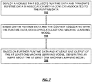
- Figure 7 is a flowchart illustrating a method of ensuring machine learning model quality.
- One or more of the steps illustrated in Figure 7 may be performed by, for example, system 100, system 200, system 300, and/or their components.
- a module that collects runtime data and transmits runtime data in association with a context associated to the runtime data is deployed.
- encapsulation/deployment 160 may deploy application 120 where application 120 associates runtime data 112 with context 121 when uploading to database 140 via upload process 130.
- At least one machine learning model is developed (704). For example, based on the runtime data and context information in database 240, machine learning operations 250 may develop machine learning modules 223-223 for deployment in application 220. Based on further runtime data and at least one output of the at least one machine learning model, an alert about the at least one machine learning model is generated (706). For example, based on further runtime data and at least one output of the at least one machine learning model drift detector 325 may determine one or more machine learning modules 323-324 is obsolete. Based on determining one or more machine learning modules 323-324 is obsolete, drift detector 325 may generate alert 326 and alert 327. Alert 326 may be provided to the entity that produces application 320. Alert 327 may be provided to machine learning operations 350.
- Figure 8 is a flowchart illustrating a method of developing a machine learning model. One or more of the steps illustrated in Figure 8 may be performed by, for example, system 100, system 200, system 300, and/or their components.
- Initial data is received (802).
- database 140 and context analysis 150 may receive an initial, uncontextualized, data set from data source 110.
- context analysis 150 may develop application 120.
- Application 120 may include context 121 and collection 122 functions that were based on the analysis by context analysis 150.
- Application 120 uploads context 121 and collection 122 information to database 140 via upload process 130.
- At least one machine learning model is developed (806). For example, based on the runtime data and context information in database 240, machine learning operations 250 may develop machine learning modules 223-223 for deployment in application 220. Based on further runtime data and at least one output of the at least one machine learning model, an alert about the at least one machine learning model is generated (808). For example, based on further runtime data and at least one output of the at least one machine learning model drift detector 325 may determine one or more machine learning modules 323-324 is obsolete. Based on determining one or more machine learning modules 323-324 is obsolete, drift detector 325 may generate alert 326 and alert 327. Alert 326 may be provided to the entity that produces application 320. Alert 327 may be provided to machine learning operations 350.
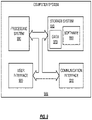
- Figure 9 is a block diagram illustrating a computer system.
- computer system 900 and/or its components include circuits, software, and/or data that implement, or are used to implement, the methods, systems and/or devices illustrated in the Figures, the corresponding discussions of the Figures, and/or are otherwise taught herein.
- the methods described above may also be stored on a non-transitory computer readable medium.
- Devices, circuits, and systems described herein may be implemented using computer-aided design tools available in the art, and embodied by computer-readable files containing software descriptions of such circuits. This includes, but is not limited to one or more elements of system 100, system 200, system 300, and/or their components. These software descriptions may be: behavioral, register transfer, logic component, transistor, and layout geometry-level descriptions.
- Data formats in which such descriptions may be implemented are stored on a non-transitory computer readable medium include, but are not limited to: formats supporting behavioral languages like C, formats supporting register transfer level (RTL) languages like Verilog and VHDL, formats supporting geometry description languages (such as GDSII, GDSIII, GDSIV, CIF, and MEBES), and other suitable formats and languages.
- RTL register transfer level
- GDSII, GDSIII, GDSIV, CIF, and MEBES formats supporting geometry description languages
- Physical files may be implemented on non-transitory machine-readable media such as: 4 mm magnetic tape, 8 mm magnetic tape, 3-1/2-inch floppy media, CDs, DVDs, hard disk drives, solid-state disk drives, solid-state memory, flash drives, and so on.
- the functionally described herein can be performed, at least in part, by one or more hardware logic components.
- illustrative types of hardware logic components include Field-programmable Gate Arrays (FPGAs), Application-specific Integrated Circuits (ASICs), Application-specific Standard Products (ASSPs), System-on-a-chip systems (SOCs), Complex Programmable Logic Devices (CPLDs), multi-core processors, graphics processing units (GPUs), etc.
- Figure 9 illustrates a block diagram of an example computer system.
- Computer system 900 includes communication interface 920, processing system 930, storage system 940, and user interface 960.
- Processing system 930 is operatively coupled to storage system 940.
- Storage system 940 stores software 950 and data 970.
- Processing system 930 is operatively coupled to communication interface 920 and user interface 960.
- Computer system 900 may comprise a programmed general-purpose computer.
- Computer system 900 may include a microprocessor.
- Computer system 900 may comprise programmable or special purpose circuitry.
- Computer system 900 may be distributed among multiple devices, processors, storage, and/or interfaces that together comprise elements 920-970.
- Communication interface 920 may comprise a network interface, modem, port, bus, link, transceiver, or other communication device. Communication interface 920 may be distributed among multiple communication devices.
- Processing system 930 may comprise a microprocessor, microcontroller, logic circuit, or other processing device. Processing system 930 may be distributed among multiple processing devices.
- User interface 960 may comprise a keyboard, mouse, voice recognition interface, microphone and speakers, graphical display, touch screen, or other type of user interface device. User interface 960 may be distributed among multiple interface devices.
- Storage system 940 may comprise a disk, tape, integrated circuit, RAM, ROM, EEPROM, flash memory, network storage, server, or other memory function. Storage system 940 may include computer readable medium. Storage system 940 may be distributed among multiple memory devices.
- Processing system 930 retrieves and executes software 950 from storage system 940. Processing system 930 may retrieve and store data 970. Processing system 930 may also retrieve and store data via communication interface 920. Processing system 900 may create or modify software 950 or data 970 to achieve a tangible result. Processing system may control communication interface 920 or user interface 960 to achieve a tangible result. Processing system 930 may retrieve and execute remotely stored software via communication interface 920.
- Software 950 and remotely stored software may comprise an operating system, utilities, drivers, networking software, and other software typically executed by a computer system.
- Software 950 may comprise an application program, applet, firmware, or other form of machine-readable processing instructions typically executed by a computer system.
- software 950 or remotely stored software may direct computer system 900 to operate as described herein.
Landscapes
- Engineering & Computer Science (AREA)
- Theoretical Computer Science (AREA)
- Software Systems (AREA)
- General Engineering & Computer Science (AREA)
- General Physics & Mathematics (AREA)
- Physics & Mathematics (AREA)
- Data Mining & Analysis (AREA)
- Artificial Intelligence (AREA)
- Computer Vision & Pattern Recognition (AREA)
- Evolutionary Computation (AREA)
- Medical Informatics (AREA)
- Computing Systems (AREA)
- Mathematical Physics (AREA)
- Evolutionary Biology (AREA)
- Life Sciences & Earth Sciences (AREA)
- Bioinformatics & Computational Biology (AREA)
- Bioinformatics & Cheminformatics (AREA)
- Computer Hardware Design (AREA)
- Quality & Reliability (AREA)
- Testing And Monitoring For Control Systems (AREA)
- Debugging And Monitoring (AREA)
Abstract
Description
- Industrial automation needs adds tiers of complexity to applications with strict definitions and workflows to attain repeatability, reliability, scalability, and security. Interconnected sensors, instruments, and other devices networked together with computers for industrial applications, (such as manufacturing and energy management) allows for data collection, exchange, and analysis, that may facilitate improvements in productivity and efficiency as well as other economic benefits.
- Applying internet of things (IoT) concepts in industrial sectors and applications may be referred to as industrial internet of things (IIoT). IIoT may include machine-to-machine (M2M) communication, big data, and machine learning. Industrial applications of IIoT include robotics, medical devices, and software-defined production processes. It should be understood that IIoT goes beyond normal consumer devices and internetworking of physical devices usually associated with IoT. IIoT may include information technology (IT) and operational technology (OT). OT refers to the networking of operational processes and industrial control systems (ICSs). This may include, for example, human machine interfaces (HMIs), supervisory control and data acquisition (SCADA) systems, distributed control systems (DCSs), and programmable logic controllers (PLCs).
-
-
Figure 1 is a diagram illustrating data flows for associating context. -
Figure 2 is a diagram illustrating data flows for deploying machine learning functions. -
Figure 3 is a diagram illustrating data flows to maintain machine learning functions. -
Figure 4 is a flowchart illustrating a method of deploying a context aware function. -
Figure 5 is a flowchart illustrating a method of deploying a machine learning function. -
Figure 6 is a flowchart illustrating a method of maintaining a machine learning function. -
Figure 7 is a flowchart illustrating a method of ensuring machine learning model quality. -
Figure 8 is a flowchart illustrating a method of developing a machine learning model. -
Figure 9 is a block diagram illustrating a computer system. - In an embodiment, data flows and data processing modules are provided to fulfill the implementation of: contextualized data collection, scalable analytics, and machine learning operations quality assurance. These modules may be implemented as standalone components, and/or bundled as a group of coordinated microservices. The conversion of raw domain expertise and knowledge into data processors, analytics, and visualization modules for industry oriented IIoT solutions is streamlined.
-
Figure 1 is a diagram illustrating data flows for associating context. InFigure 1 ,system 100 comprisesdata source 110,initial data 111,runtime data 112,application 120,upload process 130,database 140, business intelligence output 141,context analysis 150, encapsulation/deployment 160, anddisplay information 170.Application 120 includescontext 121 anddata collection 122 functions. - In
Figure 1 ,data source 110 is operatively coupled toapplication 120 andupload process 130.Application 120 is operatively coupled to uploadprocess 130.Upload process 130 is operatively coupled todatabase 140.Database 140 is operatively coupled to business intelligence output 141 andcontext analysis 150.Context analysis 150 is operatively coupled to encapsulation and encapsulation/deployment 160. Encapsulation/deployment 160 is operatively coupled toapplication 120. - The process of implementing a system that collects contextualized data begins with a
data source 110.Data source 110 may be any data source relevant to the manufacturing process that is to have artificial intelligence and/or machine learning applied to it.Data source 110 may be, for example, but is not limited to: automation computers, programmable logic controllers (PLCs), supplier/parts database, personnel records, environmental data (e.g., temperature, pressure, etc.), worker/operator information, etc. - A batch (i.e., initial data 111) of uncontextualized data is uploaded to
database 140 usingupload process 130.Upload process 130 may be based on, for example, file-transfer protocol (ftp), hypertext transfer protocol (http), transmission control protocol (tcp), user datagram protocol (udp), etc.Database 140 stores the initial batch of uploaded data. -
Database 140 is accessed bycontext analysis 150.Context analysis 150 may comprise building systems/software to extract, transform, and loadinitial data 111. -
Initial data 111 may include historical information or a stream of real-time data from many different systems. This information may be scattered across different software and be structured in various formats. Extraction entails defining the required data sources and implementing methods for gathering data from them. - When a process is implemented to gather the data, it may be placed in a temporary storage area of
database 140. While placed in this temporary area, the data may be formatted in accordance with defined standards and models. The final process is loading the structured and formatted data into a more permanent and structured area ofdatabase 140. -
Context analysis 150 may also developapplications 120 to aid in the collection ofruntime data 112. Theseapplications 120 may be deployed to, for example, a factory floor by encapsulation/deployment 160. Theseapplications 120 may be deployed by, for example, using manifest driven deployment processes. It should be understood that encapsulation/deployment 160 may deploy many instances ofapplication 120 and/or many different applications. However, for the sake of clarity and brevity,Figures 1-3 illustrate a single application. -
Application 120 collectsruntime data 112 using acollection 122 process and associates it with acontext 121.Application 120 also uploads the collected and associated runtime data usingupload process 130.Application 120 may also displayinformation 170 such as baseline trending, etc. Once contextualizedruntime data 112 is stored indatabase 140 byapplication 120, business intelligence output 141 information may be extracted and/or displayed. -
Figure 2 is a diagram illustrating data flows for deploying machine learning functions. InFigure 2 ,system 200 comprisesdata source 210,application 220,upload process 230, database 240,business intelligence output 245,machine learning operations 250,machine learning management 260, andinformation display 270.Application 220 includescontext 221,data collection 122, machine learning module/function X 223, and machine learning module/function Y 224. - In
Figure 2 ,data source 210 is operatively coupled toapplication 120.Application 220 is operatively coupled to uploadprocess 230.Upload process 230 is operatively coupled to database 240. Database 240 is operatively coupled tobusiness intelligence output 245 andmachine learning operations 250.Machine learning operations 250 is operatively coupled tomachine learning management 260.Machine learning management 260 is operatively coupled toapplication 220. - Database 240 is accessed by
machine learning operations 250. Database 240 includes collected and contextualized data (e.g., data collected byapplication 120 and/orapplication 220.)Machine learning operations 250 develops machine learning modules 223-224 based on the data in database 240. -
Machine learning management 260 receives machine learning modules 223-224 and deploysapplication 220 that implements machine learning modules 223-224. Machine learning modules 223-224 may implement reductive, reactive, predictive, etc. machine learning functions. -
Application 220 receives runtime data fromdata source 210.Application 220 collects 222 and applies acontext 221 to the received runtime data fromdata source 210.Application 220 also provides thecontext 221 and runtime data to machine learning modules 223-224. The contextualized data and the outputs of machine learning modules 223-224 are sent to database 240 via uploadprocess 230.Application 220, and machine learning modules 223-224 may provide information forinformation display 270. The information displayed 270 may include trending and prediction information. -
Figure 3 is a diagram illustrating data flows to maintain machine learning functions. InFigure 3 ,system 300 comprisesdata source 310, application 320, uploadprocess 330,database 340, business intelligence output345,machine learning operations 350,machine learning management 360,information display 370, and alert 327. Application 320 includes context 321,data collection 322, machine learning module/function X 323, machine learning module/function Y 324,drift detector 325, and alert 326. - In
Figure 3 ,data source 310 is operatively coupled to application 320. Application 320 is operatively coupled to uploadprocess 330. Uploadprocess 330 is operatively coupled todatabase 340.Database 340 is operatively coupled tobusiness intelligence output 345 andmachine learning operations 350.Machine learning operations 350 is operatively coupled tomachine learning management 360.Machine learning management 360 is operatively coupled to application 320. Application 320 is operatively coupled to alert 327.Alert 327 is operatively coupled tomachine learning operations 350. - Application 320 receives runtime data from
data source 310. Application 320 collects (using data collection 322) and applies a context to the received runtime data fromdata source 310. Application 320 also provides the runtime data to machine learning modules 323-324. The contextualized data and the outputs of machine learning modules 323-324 are sent todatabase 340 via uploadprocess 330. Application 320, and machine learning modules 323-324 may provide information forinformation display 370. The information displayed 370 may include trending, prediction, and/or drift information. -
Drift detector 325 receives the outputs of machine learning modules 323-324.Drift detector 325 analyzes the outputs of machine learning modules 323-324 to determine if one or more of machine learning modules 323-324 is obsolete. If one or more machine learning modules 323-324 is determined to be obsolete, drift observer generates alert 326 and alert 327.Alert 326 may be provided to the entity that produces application 320.Alert 327 is provided tomachine learning operations 350. In response to alert 327,machine learning operations 350 may retrain, modify and/or generate new machine learning models 323-324 and/or application 320.Machine learning management 360 may re-deploy the new or modified application 320 and/or machine learning modules 323-324. -
Figure 4 is a flowchart illustrating a method of deploying a context aware function. One or more of the steps illustrated inFigure 4 may be performed by, for example,system 100,system 200,system 300, and/or their components. An initial data batch is received from a data source (402). For example,database 140 andcontext analysis 150 may receive an initial, uncontextualized, data set fromdata source 110. - The context is analyzed (404). For example, based on the data batch is received from
data source 110,context analysis 150 may analyze and document the context of data. An application is deployed with a collection function (406). For example, encapsulation/deployment 160 may deployapplication 120.Application 120 may includecontext 121 andcollection 122 functions that were based on the analysis bycontext analysis 150. - The application uploads data for further analysis (408). For example,
application 120 may upload contextualized data todatabase 140 via uploadprocess 130. This contextualized data may be further analyzed (e.g., bymachine learning operations 250.) -
Figure 5 is a flowchart illustrating a method of deploying a machine learning function. One or more of the steps illustrated inFigure 5 may be performed by, for example,system 100,system 200,system 300, and/or their components. By an application having artificial intelligence models, data from a data source is received (502). For example,application 220, which has machine learning modules 223-224, may collect data fromdata source 210. - The application uploads data and artificial intelligence model outputs in association with the data (504). For example,
application 220 may upload contextualized data fromdata source 210 and the outputs of machine learning modules 223-224 associated with that contextualized data to database 240 via uploadprocess 230. -
Figure 6 is a flowchart illustrating a method of maintaining a machine learning function. One or more of the steps illustrated inFigure 6 may be performed by, for example,system 100,system 200,system 300, and/or their components. An application is deployed that has at least one collection function, at least one artificial intelligence model, and at least one drift detector (602). For example,machine learning management 360 may deploy application 320 that includesdata collection 322, machine learning modules/functions 323-324, and driftdetector 325. - The application uploads data for further analysis (604). For example, application 320 may upload contextualized data to
database 340 via uploadprocess 330. This contextualized data may be further analyzed (e.g., bymachine learning operations 350.) The drift detector detects drift in an artificial intelligence model (606). For example,drift detector 325 may determine that one or more of machine learning modules 323-324 is obsolete. - An alert is sent (608). For example, if one or more machine learning modules 323-324 is determined to be obsolete by
drift detector 325,drift detector 325 may generate alert 326 and alert 327.Alert 326 may be provided to the entity that produces application 320.Alert 327 may be provided tomachine learning operations 350. -
Figure 7 is a flowchart illustrating a method of ensuring machine learning model quality. One or more of the steps illustrated inFigure 7 may be performed by, for example,system 100,system 200,system 300, and/or their components. A module that collects runtime data and transmits runtime data in association with a context associated to the runtime data is deployed. For example, encapsulation/deployment 160 may deployapplication 120 whereapplication 120 associates runtimedata 112 withcontext 121 when uploading todatabase 140 via uploadprocess 130. - Based on the runtime data and the context associated with the runtime data, at least one machine learning model is developed (704). For example, based on the runtime data and context information in database 240,
machine learning operations 250 may develop machine learning modules 223-223 for deployment inapplication 220. Based on further runtime data and at least one output of the at least one machine learning model, an alert about the at least one machine learning model is generated (706). For example, based on further runtime data and at least one output of the at least one machine learningmodel drift detector 325 may determine one or more machine learning modules 323-324 is obsolete. Based on determining one or more machine learning modules 323-324 is obsolete,drift detector 325 may generate alert 326 and alert 327.Alert 326 may be provided to the entity that produces application 320.Alert 327 may be provided tomachine learning operations 350. -
Figure 8 is a flowchart illustrating a method of developing a machine learning model. One or more of the steps illustrated inFigure 8 may be performed by, for example,system 100,system 200,system 300, and/or their components. Initial data is received (802). For example,database 140 andcontext analysis 150 may receive an initial, uncontextualized, data set fromdata source 110. - Based on the previous data, a module that collects runtime data and transmits runtime data in association with a context is developed (804). For example,
context analysis 150 may developapplication 120.Application 120 may includecontext 121 andcollection 122 functions that were based on the analysis bycontext analysis 150.Application 120uploads context 121 andcollection 122 information todatabase 140 via uploadprocess 130. - Based on the runtime data and the context associated with the runtime data, at least one machine learning model is developed (806). For example, based on the runtime data and context information in database 240,
machine learning operations 250 may develop machine learning modules 223-223 for deployment inapplication 220. Based on further runtime data and at least one output of the at least one machine learning model, an alert about the at least one machine learning model is generated (808). For example, based on further runtime data and at least one output of the at least one machine learningmodel drift detector 325 may determine one or more machine learning modules 323-324 is obsolete. Based on determining one or more machine learning modules 323-324 is obsolete,drift detector 325 may generate alert 326 and alert 327.Alert 326 may be provided to the entity that produces application 320.Alert 327 may be provided tomachine learning operations 350. -
Figure 9 is a block diagram illustrating a computer system. In an embodiment,computer system 900 and/or its components include circuits, software, and/or data that implement, or are used to implement, the methods, systems and/or devices illustrated in the Figures, the corresponding discussions of the Figures, and/or are otherwise taught herein. The methods described above may also be stored on a non-transitory computer readable medium. Devices, circuits, and systems described herein may be implemented using computer-aided design tools available in the art, and embodied by computer-readable files containing software descriptions of such circuits. This includes, but is not limited to one or more elements ofsystem 100,system 200,system 300, and/or their components. These software descriptions may be: behavioral, register transfer, logic component, transistor, and layout geometry-level descriptions. - Data formats in which such descriptions may be implemented are stored on a non-transitory computer readable medium include, but are not limited to: formats supporting behavioral languages like C, formats supporting register transfer level (RTL) languages like Verilog and VHDL, formats supporting geometry description languages (such as GDSII, GDSIII, GDSIV, CIF, and MEBES), and other suitable formats and languages. Physical files may be implemented on non-transitory machine-readable media such as: 4 mm magnetic tape, 8 mm magnetic tape, 3-1/2-inch floppy media, CDs, DVDs, hard disk drives, solid-state disk drives, solid-state memory, flash drives, and so on.
- Alternatively, or in addition, the functionally described herein can be performed, at least in part, by one or more hardware logic components. For example, and without limitation, illustrative types of hardware logic components that can be used include Field-programmable Gate Arrays (FPGAs), Application-specific Integrated Circuits (ASICs), Application-specific Standard Products (ASSPs), System-on-a-chip systems (SOCs), Complex Programmable Logic Devices (CPLDs), multi-core processors, graphics processing units (GPUs), etc.
-
Figure 9 illustrates a block diagram of an example computer system.Computer system 900 includescommunication interface 920,processing system 930,storage system 940, anduser interface 960.Processing system 930 is operatively coupled tostorage system 940.Storage system 940stores software 950 anddata 970.Processing system 930 is operatively coupled tocommunication interface 920 anduser interface 960.Computer system 900 may comprise a programmed general-purpose computer.Computer system 900 may include a microprocessor.Computer system 900 may comprise programmable or special purpose circuitry.Computer system 900 may be distributed among multiple devices, processors, storage, and/or interfaces that together comprise elements 920-970. -
Communication interface 920 may comprise a network interface, modem, port, bus, link, transceiver, or other communication device.Communication interface 920 may be distributed among multiple communication devices.Processing system 930 may comprise a microprocessor, microcontroller, logic circuit, or other processing device.Processing system 930 may be distributed among multiple processing devices.User interface 960 may comprise a keyboard, mouse, voice recognition interface, microphone and speakers, graphical display, touch screen, or other type of user interface device.User interface 960 may be distributed among multiple interface devices.Storage system 940 may comprise a disk, tape, integrated circuit, RAM, ROM, EEPROM, flash memory, network storage, server, or other memory function.Storage system 940 may include computer readable medium.Storage system 940 may be distributed among multiple memory devices. -
Processing system 930 retrieves and executessoftware 950 fromstorage system 940.Processing system 930 may retrieve andstore data 970.Processing system 930 may also retrieve and store data viacommunication interface 920.Processing system 900 may create or modifysoftware 950 ordata 970 to achieve a tangible result. Processing system may controlcommunication interface 920 oruser interface 960 to achieve a tangible result.Processing system 930 may retrieve and execute remotely stored software viacommunication interface 920. -
Software 950 and remotely stored software may comprise an operating system, utilities, drivers, networking software, and other software typically executed by a computer system.Software 950 may comprise an application program, applet, firmware, or other form of machine-readable processing instructions typically executed by a computer system. When executed by processingsystem 930,software 950 or remotely stored software may directcomputer system 900 to operate as described herein. - Implementations discussed herein include, but are not limited to, the following examples:
- Example 1: A method, comprising: deploying a module that collects runtime data and transmits runtime data in association with a context associated to the runtime data; based on the runtime data and the context associated with the runtime data, developing at least one machine learning model; and, based on further runtime data and at least one output of the at least one machine learning model, generating an alert about the at least one machine learning model.
- Example 2: The method of claim 1, further comprising: receiving initial data; and, based on the initial data, developing the module that collects runtime data and transmits runtime data in association with the context.
- Example 3: The method of claim 2, wherein the at least one machine learning model performs a data reduction function.
- Example 4: The method of claim 3, wherein the at least one machine learning model performs a reactive function.
- Example 5: The method of claim 3, wherein the at least one machine learning model performs a predictive function.
- Example 6: The method of claim 1, wherein the alert about the at least one machine learning model is based on a first indicator that the at least one machine learning model is obsolete.
- Example 7: The method of claim 6, wherein the alert about the at least one machine learning model is based on a second indicator that the at least one machine learning model has drifted.
- Example 8: A method, comprising: receiving initial data; based on the initial data, developing a module that collects runtime data and transmits runtime data in association with a context; and, based on the runtime data and the context associated with the runtime data, developing at least one machine learning model.
- Example 9: The method of claim 8, further comprising: based on further runtime data and at least one output of the at least one machine learning model, generating an alert about the at least one machine learning model.
- Example 10: The method of claim 9, wherein the at least one machine learning model performs a data reduction function.
- Example 11: The method of claim 9, wherein the at least one machine learning model performs a reactive function.
- Example 12: The method of claim 9, wherein the at least one machine learning model performs a predictive function.
- Example 13: The method of claim 9, wherein the alert about the at least one machine learning model is based on a first indicator that the at least one machine learning model is obsolete.
- Example 14: The method of claim 13, wherein the alert about the at least one machine learning model is based on a second indicator that the at least one machine learning model has drifted.
- Example 15: A non-transitory computer readable medium having instructions stored thereon that, when executed by a computer, at least instruct the computer to: receive initial data; deploy a first module that collects runtime data and transmits runtime data in association with a context, the first module to be developed based on the initial data; and, develop at least one machine learning model based on the runtime data and the context associated with the runtime data.
- Example 16: The non-transitory computer readable medium of claim 15, wherein the computer is further instructed to: deploy the at least one machine learning model.
- Example 17: The non-transitory computer readable medium of claim 16, wherein the computer is further instructed to: receive an alert about the at least one machine learning model that was generated based on further runtime data and at least one output of the at least one machine learning model.
- Example 18: The non-transitory computer readable medium of claim 17, wherein the at least one machine learning model performs a data reduction function.
- Example 19: The non-transitory computer readable medium of claim 17, wherein the at least one machine learning model performs a reactive function.
- Example 20: The non-transitory computer readable medium of claim 17, wherein the at least one machine learning model performs a predictive function.
- The foregoing description of the invention has been presented for purposes of illustration and description. It is not intended to be exhaustive or to limit the invention to the precise form disclosed, and other modifications and variations may be possible in light of the above teachings. The embodiment was chosen and described in order to best explain the principles of the invention and its practical application to thereby enable others skilled in the art to best utilize the invention in various embodiments and various modifications as are suited to the particular use contemplated. It is intended that the appended claims be construed to include other alternative embodiments of the invention except insofar as limited by the prior art.
Claims (15)
- A method, comprising:deploying a module that collects runtime data and transmits runtime data in association with a context associated to the runtime data;based on the runtime data and the context associated with the runtime data, developing at least one machine learning model; and,based on further runtime data and at least one output of the at least one machine learning model, generating an alert about the at least one machine learning model.
- The method of claim 1, further comprising:receiving initial data; and,based on the initial data, developing the module that collects runtime data and transmits runtime data in association with the context.
- The method of claim 2, wherein the at least one machine learning model performs a data reduction function.
- The method of claim 3, wherein the at least one machine learning model performs a reactive function, or
wherein the at least one machine learning model performs a predictive function. - The method of one of claims 1 to 4, wherein the alert about the at least one machine learning model is based on a first indicator that the at least one machine learning model is obsolete.
- The method of claim 5, wherein the alert about the at least one machine learning model is based on a second indicator that the at least one machine learning model has drifted.
- A method, comprising:receiving initial data;based on the initial data, developing a module that collects runtime data and transmits runtime data in association with a context; and,based on the runtime data and the context associated with the runtime data, developing at least one machine learning model.
- The method of claim 7, further comprising:
based on further runtime data and at least one output of the at least one machine learning model, generating an alert about the at least one machine learning model. - The method of claim 8, wherein the at least one machine learning model performs one of:a data reduction function;a reactive function; anda predictive function.
- The method of claim 8 or 9, wherein the alert about the at least one machine learning model is based on a first indicator that the at least one machine learning model is obsolete.
- The method of claim 10, wherein the alert about the at least one machine learning model is based on a second indicator that the at least one machine learning model has drifted.
- A non-transitory computer readable medium having instructions stored thereon that, when executed by a computer, at least instruct the computer to:receive initial data;deploy a first module that collects runtime data and transmits runtime data in association with a context, the first module to be developed based on the initial data; and,develop at least one machine learning model based on the runtime data and the context associated with the runtime data.
- The non-transitory computer readable medium of claim 12, wherein the computer is further instructed to:
deploy the at least one machine learning model. - The non-transitory computer readable medium of claim 13, wherein the computer is further instructed to:
receive an alert about the at least one machine learning model that was generated based on further runtime data and at least one output of the at least one machine learning model. - The non-transitory computer readable medium of claim 14, wherein the at least one machine learning model performs:a data reduction function;a reactive function; ora predictive function.
Applications Claiming Priority (1)
| Application Number | Priority Date | Filing Date | Title |
|---|---|---|---|
| US17/230,115 US12327118B2 (en) | 2021-04-14 | 2021-04-14 | Industrial internet of things AIOPs workflows |
Publications (1)
| Publication Number | Publication Date |
|---|---|
| EP4075279A1 true EP4075279A1 (en) | 2022-10-19 |
Family
ID=81580814
Family Applications (1)
| Application Number | Title | Priority Date | Filing Date |
|---|---|---|---|
| EP22167590.3A Pending EP4075279A1 (en) | 2021-04-14 | 2022-04-11 | Industrial internet of things aiops workflows |
Country Status (2)
| Country | Link |
|---|---|
| US (1) | US12327118B2 (en) |
| EP (1) | EP4075279A1 (en) |
Citations (3)
| Publication number | Priority date | Publication date | Assignee | Title |
|---|---|---|---|---|
| US20190197354A1 (en) * | 2017-12-22 | 2019-06-27 | Motorola Solutions, Inc | Method, device, and system for adaptive training of machine learning models via detected in-field contextual sensor events and associated located and retrieved digital audio and/or video imaging |
| US20200151619A1 (en) * | 2018-11-09 | 2020-05-14 | Hewlett Packard Enterprise Development Lp | Systems and methods for determining machine learning training approaches based on identified impacts of one or more types of concept drift |
| US20200327371A1 (en) * | 2019-04-09 | 2020-10-15 | FogHorn Systems, Inc. | Intelligent Edge Computing Platform with Machine Learning Capability |
Family Cites Families (2)
| Publication number | Priority date | Publication date | Assignee | Title |
|---|---|---|---|---|
| US10984338B2 (en) * | 2015-05-28 | 2021-04-20 | Raytheon Technologies Corporation | Dynamically updated predictive modeling to predict operational outcomes of interest |
| US10620612B2 (en) * | 2017-06-08 | 2020-04-14 | Rockwell Automation Technologies, Inc. | Predictive maintenance and process supervision using a scalable industrial analytics platform |
-
2021
- 2021-04-14 US US17/230,115 patent/US12327118B2/en active Active
-
2022
- 2022-04-11 EP EP22167590.3A patent/EP4075279A1/en active Pending
Patent Citations (3)
| Publication number | Priority date | Publication date | Assignee | Title |
|---|---|---|---|---|
| US20190197354A1 (en) * | 2017-12-22 | 2019-06-27 | Motorola Solutions, Inc | Method, device, and system for adaptive training of machine learning models via detected in-field contextual sensor events and associated located and retrieved digital audio and/or video imaging |
| US20200151619A1 (en) * | 2018-11-09 | 2020-05-14 | Hewlett Packard Enterprise Development Lp | Systems and methods for determining machine learning training approaches based on identified impacts of one or more types of concept drift |
| US20200327371A1 (en) * | 2019-04-09 | 2020-10-15 | FogHorn Systems, Inc. | Intelligent Edge Computing Platform with Machine Learning Capability |
Also Published As
| Publication number | Publication date |
|---|---|
| US12327118B2 (en) | 2025-06-10 |
| US20220334838A1 (en) | 2022-10-20 |
Similar Documents
| Publication | Publication Date | Title |
|---|---|---|
| US10740293B2 (en) | Modular control manifest generator for cloud automation | |
| US11558449B1 (en) | Industrial controller system and interactive graphical user interfaces related thereto | |
| EP3335083B1 (en) | Rich contextualization of automation data | |
| EP2924562B1 (en) | Multiple controllers configuration management interface for system connectivity | |
| US10739746B2 (en) | Using soft-sensors in a programmable logic controller | |
| EP3314340B1 (en) | Control contextualization and reasoning about control | |
| JP6551565B2 (en) | Process analysis apparatus, process analysis method, and process analysis program | |
| EP2924572B1 (en) | Cloud-level analytics for boiler networks | |
| EP3361330B1 (en) | Event analyzing device, event analyzing system, event analyzing method, event analyzing program, and non-transitory computer readable storage medium | |
| EP3037901A2 (en) | Cloud-based emulation and modeling for automation systems | |
| EP3121667A1 (en) | Snapshot management architecture for process control operator training system lifecycle | |
| US20240061983A1 (en) | Digital avatar platform | |
| US10901400B2 (en) | Set point optimization in multi-resolution processes | |
| EP3376320A1 (en) | Control device | |
| US20230359864A1 (en) | Large-scale matrix operations on hardware accelerators | |
| EP4250024A1 (en) | Edge device feature engineering application | |
| US12327118B2 (en) | Industrial internet of things AIOPs workflows | |
| Sølvsberg et al. | Analysis-oriented structure for runtime data in Industry 4.0 asset administration shells | |
| JP7651741B2 (en) | Method, non-transitory computer readable medium and system for monitoring a manufacturing process - Patents.com | |
| Webert et al. | A practical investigation of ML and Industry 4.0 for reactive fault detection in manufacturing systems | |
| Westbrink et al. | Integrated IPC for data-driven fault detection | |
| CN117651977A (en) | Methods and devices for debugging artificial intelligence-based inspection systems | |
| EP4354336A1 (en) | Automatic generation of as-run results in a three demensional model using augmented reality | |
| EP4513401A1 (en) | Multi-sensor system for operation status monitoring | |
| GB2643758A (en) | Visual programming system |
Legal Events
| Date | Code | Title | Description |
|---|---|---|---|
| PUAI | Public reference made under article 153(3) epc to a published international application that has entered the european phase |
Free format text: ORIGINAL CODE: 0009012 |
|
| STAA | Information on the status of an ep patent application or granted ep patent |
Free format text: STATUS: THE APPLICATION HAS BEEN PUBLISHED |
|
| AK | Designated contracting states |
Kind code of ref document: A1 Designated state(s): AL AT BE BG CH CY CZ DE DK EE ES FI FR GB GR HR HU IE IS IT LI LT LU LV MC MK MT NL NO PL PT RO RS SE SI SK SM TR |
|
| STAA | Information on the status of an ep patent application or granted ep patent |
Free format text: STATUS: REQUEST FOR EXAMINATION WAS MADE |
|
| 17P | Request for examination filed |
Effective date: 20230228 |
|
| RBV | Designated contracting states (corrected) |
Designated state(s): AL AT BE BG CH CY CZ DE DK EE ES FI FR GB GR HR HU IE IS IT LI LT LU LV MC MK MT NL NO PL PT RO RS SE SI SK SM TR |
|
| STAA | Information on the status of an ep patent application or granted ep patent |
Free format text: STATUS: EXAMINATION IS IN PROGRESS |
|
| 17Q | First examination report despatched |
Effective date: 20230530 |