EP4075248A1 - Input check device and input check method - Google Patents
Input check device and input check method Download PDFInfo
- Publication number
- EP4075248A1 EP4075248A1 EP22165132.6A EP22165132A EP4075248A1 EP 4075248 A1 EP4075248 A1 EP 4075248A1 EP 22165132 A EP22165132 A EP 22165132A EP 4075248 A1 EP4075248 A1 EP 4075248A1
- Authority
- EP
- European Patent Office
- Prior art keywords
- pressing force
- operating
- threshold
- identifying
- minimum value
- Prior art date
- Legal status (The legal status is an assumption and is not a legal conclusion. Google has not performed a legal analysis and makes no representation as to the accuracy of the status listed.)
- Granted
Links
Images


Classifications
-
- G—PHYSICS
- G06—COMPUTING OR CALCULATING; COUNTING
- G06F—ELECTRIC DIGITAL DATA PROCESSING
- G06F3/00—Input arrangements for transferring data to be processed into a form capable of being handled by the computer; Output arrangements for transferring data from processing unit to output unit, e.g. interface arrangements
- G06F3/01—Input arrangements or combined input and output arrangements for interaction between user and computer
- G06F3/03—Arrangements for converting the position or the displacement of a member into a coded form
- G06F3/041—Digitisers, e.g. for touch screens or touch pads, characterised by the transducing means
- G06F3/044—Digitisers, e.g. for touch screens or touch pads, characterised by the transducing means by capacitive means
-
- G—PHYSICS
- G06—COMPUTING OR CALCULATING; COUNTING
- G06F—ELECTRIC DIGITAL DATA PROCESSING
- G06F3/00—Input arrangements for transferring data to be processed into a form capable of being handled by the computer; Output arrangements for transferring data from processing unit to output unit, e.g. interface arrangements
- G06F3/01—Input arrangements or combined input and output arrangements for interaction between user and computer
- G06F3/03—Arrangements for converting the position or the displacement of a member into a coded form
- G06F3/041—Digitisers, e.g. for touch screens or touch pads, characterised by the transducing means
- G06F3/044—Digitisers, e.g. for touch screens or touch pads, characterised by the transducing means by capacitive means
- G06F3/0447—Position sensing using the local deformation of sensor cells
-
- G—PHYSICS
- G06—COMPUTING OR CALCULATING; COUNTING
- G06F—ELECTRIC DIGITAL DATA PROCESSING
- G06F3/00—Input arrangements for transferring data to be processed into a form capable of being handled by the computer; Output arrangements for transferring data from processing unit to output unit, e.g. interface arrangements
- G06F3/01—Input arrangements or combined input and output arrangements for interaction between user and computer
- G06F3/03—Arrangements for converting the position or the displacement of a member into a coded form
- G06F3/041—Digitisers, e.g. for touch screens or touch pads, characterised by the transducing means
- G06F3/0414—Digitisers, e.g. for touch screens or touch pads, characterised by the transducing means using force sensing means to determine a position
-
- G—PHYSICS
- G06—COMPUTING OR CALCULATING; COUNTING
- G06F—ELECTRIC DIGITAL DATA PROCESSING
- G06F3/00—Input arrangements for transferring data to be processed into a form capable of being handled by the computer; Output arrangements for transferring data from processing unit to output unit, e.g. interface arrangements
- G06F3/01—Input arrangements or combined input and output arrangements for interaction between user and computer
- G06F3/03—Arrangements for converting the position or the displacement of a member into a coded form
- G06F3/041—Digitisers, e.g. for touch screens or touch pads, characterised by the transducing means
- G06F3/0414—Digitisers, e.g. for touch screens or touch pads, characterised by the transducing means using force sensing means to determine a position
- G06F3/04146—Digitisers, e.g. for touch screens or touch pads, characterised by the transducing means using force sensing means to determine a position using pressure sensitive conductive elements delivering a boolean signal and located between crossing sensing lines, e.g. located between X and Y sensing line layers
-
- G—PHYSICS
- G06—COMPUTING OR CALCULATING; COUNTING
- G06F—ELECTRIC DIGITAL DATA PROCESSING
- G06F3/00—Input arrangements for transferring data to be processed into a form capable of being handled by the computer; Output arrangements for transferring data from processing unit to output unit, e.g. interface arrangements
- G06F3/01—Input arrangements or combined input and output arrangements for interaction between user and computer
- G06F3/03—Arrangements for converting the position or the displacement of a member into a coded form
- G06F3/041—Digitisers, e.g. for touch screens or touch pads, characterised by the transducing means
- G06F3/0416—Control or interface arrangements specially adapted for digitisers
-
- G—PHYSICS
- G06—COMPUTING OR CALCULATING; COUNTING
- G06F—ELECTRIC DIGITAL DATA PROCESSING
- G06F3/00—Input arrangements for transferring data to be processed into a form capable of being handled by the computer; Output arrangements for transferring data from processing unit to output unit, e.g. interface arrangements
- G06F3/01—Input arrangements or combined input and output arrangements for interaction between user and computer
- G06F3/03—Arrangements for converting the position or the displacement of a member into a coded form
- G06F3/041—Digitisers, e.g. for touch screens or touch pads, characterised by the transducing means
- G06F3/044—Digitisers, e.g. for touch screens or touch pads, characterised by the transducing means by capacitive means
- G06F3/0445—Digitisers, e.g. for touch screens or touch pads, characterised by the transducing means by capacitive means using two or more layers of sensing electrodes, e.g. using two layers of electrodes separated by a dielectric layer
-
- G—PHYSICS
- G06—COMPUTING OR CALCULATING; COUNTING
- G06F—ELECTRIC DIGITAL DATA PROCESSING
- G06F3/00—Input arrangements for transferring data to be processed into a form capable of being handled by the computer; Output arrangements for transferring data from processing unit to output unit, e.g. interface arrangements
- G06F3/01—Input arrangements or combined input and output arrangements for interaction between user and computer
- G06F3/03—Arrangements for converting the position or the displacement of a member into a coded form
- G06F3/041—Digitisers, e.g. for touch screens or touch pads, characterised by the transducing means
- G06F3/044—Digitisers, e.g. for touch screens or touch pads, characterised by the transducing means by capacitive means
- G06F3/0446—Digitisers, e.g. for touch screens or touch pads, characterised by the transducing means by capacitive means using a grid-like structure of electrodes in at least two directions, e.g. using row and column electrodes
-
- G—PHYSICS
- G06—COMPUTING OR CALCULATING; COUNTING
- G06F—ELECTRIC DIGITAL DATA PROCESSING
- G06F3/00—Input arrangements for transferring data to be processed into a form capable of being handled by the computer; Output arrangements for transferring data from processing unit to output unit, e.g. interface arrangements
- G06F3/01—Input arrangements or combined input and output arrangements for interaction between user and computer
- G06F3/048—Interaction techniques based on graphical user interfaces [GUI]
- G06F3/0481—Interaction techniques based on graphical user interfaces [GUI] based on specific properties of the displayed interaction object or a metaphor-based environment, e.g. interaction with desktop elements like windows or icons, or assisted by a cursor's changing behaviour or appearance
- G06F3/04817—Interaction techniques based on graphical user interfaces [GUI] based on specific properties of the displayed interaction object or a metaphor-based environment, e.g. interaction with desktop elements like windows or icons, or assisted by a cursor's changing behaviour or appearance using icons
-
- G—PHYSICS
- G06—COMPUTING OR CALCULATING; COUNTING
- G06F—ELECTRIC DIGITAL DATA PROCESSING
- G06F3/00—Input arrangements for transferring data to be processed into a form capable of being handled by the computer; Output arrangements for transferring data from processing unit to output unit, e.g. interface arrangements
- G06F3/01—Input arrangements or combined input and output arrangements for interaction between user and computer
- G06F3/048—Interaction techniques based on graphical user interfaces [GUI]
- G06F3/0484—Interaction techniques based on graphical user interfaces [GUI] for the control of specific functions or operations, e.g. selecting or manipulating an object, an image or a displayed text element, setting a parameter value or selecting a range
- G06F3/04847—Interaction techniques to control parameter settings, e.g. interaction with sliders or dials
-
- G—PHYSICS
- G06—COMPUTING OR CALCULATING; COUNTING
- G06F—ELECTRIC DIGITAL DATA PROCESSING
- G06F3/00—Input arrangements for transferring data to be processed into a form capable of being handled by the computer; Output arrangements for transferring data from processing unit to output unit, e.g. interface arrangements
- G06F3/01—Input arrangements or combined input and output arrangements for interaction between user and computer
- G06F3/048—Interaction techniques based on graphical user interfaces [GUI]
- G06F3/0487—Interaction techniques based on graphical user interfaces [GUI] using specific features provided by the input device, e.g. functions controlled by the rotation of a mouse with dual sensing arrangements, or of the nature of the input device, e.g. tap gestures based on pressure sensed by a digitiser
- G06F3/0488—Interaction techniques based on graphical user interfaces [GUI] using specific features provided by the input device, e.g. functions controlled by the rotation of a mouse with dual sensing arrangements, or of the nature of the input device, e.g. tap gestures based on pressure sensed by a digitiser using a touch-screen or digitiser, e.g. input of commands through traced gestures
-
- H—ELECTRICITY
- H03—ELECTRONIC CIRCUITRY
- H03K—PULSE TECHNIQUE
- H03K17/00—Electronic switching or gating, i.e. not by contact-making and –breaking
- H03K17/94—Electronic switching or gating, i.e. not by contact-making and –breaking characterised by the way in which the control signals are generated
- H03K17/965—Switches controlled by moving an element forming part of the switch
- H03K17/975—Switches controlled by moving an element forming part of the switch using a capacitive movable element
-
- G—PHYSICS
- G06—COMPUTING OR CALCULATING; COUNTING
- G06F—ELECTRIC DIGITAL DATA PROCESSING
- G06F2203/00—Indexing scheme relating to G06F3/00 - G06F3/048
- G06F2203/041—Indexing scheme relating to G06F3/041 - G06F3/045
- G06F2203/04105—Pressure sensors for measuring the pressure or force exerted on the touch surface without providing the touch position
-
- G—PHYSICS
- G06—COMPUTING OR CALCULATING; COUNTING
- G06F—ELECTRIC DIGITAL DATA PROCESSING
- G06F2203/00—Indexing scheme relating to G06F3/00 - G06F3/048
- G06F2203/041—Indexing scheme relating to G06F3/041 - G06F3/045
- G06F2203/04111—Cross over in capacitive digitiser, i.e. details of structures for connecting electrodes of the sensing pattern where the connections cross each other, e.g. bridge structures comprising an insulating layer, or vias through substrate
-
- H—ELECTRICITY
- H03—ELECTRONIC CIRCUITRY
- H03K—PULSE TECHNIQUE
- H03K2217/00—Indexing scheme related to electronic switching or gating, i.e. not by contact-making or -breaking covered by H03K17/00
- H03K2217/94—Indexing scheme related to electronic switching or gating, i.e. not by contact-making or -breaking covered by H03K17/00 characterised by the way in which the control signal is generated
- H03K2217/965—Switches controlled by moving an element forming part of the switch
- H03K2217/9651—Switches controlled by moving an element forming part of the switch the moving element acting on a force, e.g. pressure sensitive element
Definitions
- the disclosure herein relates to an input check device and an input check method.
- an operating part that accepts inputs from the operator, a contact detection part that detects contacts on the operating part, a piezoelectric element that detects changes of pressure loads on the operating part, and a control part that executes a first process when the piezoelectric element detects a change with the first pressure load
- the control part executes a second process.
- the amount of change with the second pressure load is less than or equal to the amount of change with the first pressure load.
- the input of the first pressure load is what is commonly referred to as a "half-press”
- the input of the second pressure load is what is commonly referred to as a "full press" (see, for example, patent document 1) .
- Patent Document 1 International Publication No. WO2017-122466A1
- an input operation is performed once and performed again later, instead of input methods to use pressure loads that vary significantly such as a half-press and a full-press.
- the first input operation to perform is an operation for selecting an operating part, and in which the second input operation is performed with the same pressure load as that of the first input operation to confirm the content of the selection made in the first input operation.
- the invention relates to an input check device and method according to the appended claims. Embodiments are disclosed in the dependent claims.
- An input check device includes a coordinate detection part configured to detect coordinates of a touch operation a user performs on an operating surface when operating an operating part through the operating surface, a pressing force detection part configured to detect a pressing force of the touch operation, and an identifying part configured to determine whether the operating part is ON or OFF based on the pressing force detected in the pressing force detection part, and, in this input check device, after determining that the operating part is switched from ON mode to OFF mode, the identifying part detects a minimum value of the pressing force, and when, following the detection of the minimum value, the pressing force surpasses a predetermined threshold, the predetermined threshold being set based on the minimum value and being greater than the minimum value, the identifying part determines that the operating part is switched from OFF to ON.
- an input check device having excellent operability, and an input check method.
- FIG. 1 is a diagram showing electrical equipment 100 according to an embodiment.
- the electrical equipment 100 includes a housing 101, a touch panel 110, a display panel 120, a pressing force detection part 130, and a control device 140.
- the touch panel 110 is an example of a coordinate detection part
- the display panel 120 is an example of a display part.
- the portion of the electrical equipment 100 excluding the housing 101 constitutes the input check device 100A. Therefore, the touch panel 110, the display panel 120, the pressing force detection part 130, and the control device 140, which are included in the input check device 100A, are marked with the reference sign of the input check device 100A in parentheses. Furthermore, the method executed on the input check device 100A is the input check method according to the embodiment. Note that the input check device 100A may include the housing 101.
- the XYZ coordinate system will be defined and described, in which the direction parallel to the X axis (X direction), the direction parallel to the Y axis (Y direction), and the direction parallel to the Z axis (Z direction) are orthogonal to each other.
- the -Z direction side may be referred to with words such as “the lower side,” “below,” and so forth
- the +Z direction side may be referred to with words such as "the upper side,” “above,” and so forth, but this is only for ease of explanation, and does not refer to the general concept of up and down.
- a plan view means a view in the X-Y plane.
- each component may be shown in exaggerated length, thickness, breadth, and so forth, for ease of understanding of the configuration.
- the housing 101 includes an operating surface 101A, and accommodates the touch panel 110, the display panel 120, the pressing force detection part 130, and the control device 140.
- the housing 101 is made of resin, for example.
- the operating surface 101A is the surface of a transparent plate located above the touch panel 110.
- the transparent plate is made of glass or resin, for example.
- the thickness of the housing 101 in the Z direction is exaggerated.
- the operating surface 101A is parallel to the XY plane.
- the touch panel 110, the display panel 120, and the pressing force detection part 130 are provided in this order from the operating surface 101A downward. Note that the order in which the touch panel 110, the display panel 120, and the pressing force detection part 130 are provided is not limited to this.
- the electrical equipment 100 detects, in the touch panel 110, the coordinates of a touch operation the user performs on the operating surface 101A, detects the pressing force of the touch operation in the pressing force detection part 130, accepts a touch operation on an operating part, which the control device 140 shows on the display panel 120 in a GUI (Graphic User Interface), based on the coordinates detected on the touch panel 110 and the pressing force detected in the pressing force detection part 130, and controls the display on the display panel 120 based on the content of the operation.
- the operating part may be an image of an operating icon, an image of an operation menu, an image of an operation switch, and so forth shown on the display panel 120.
- a touch operation is an input operation the user perform by touching the operating surface 101A with his/her fingertip FT, and is an input operation whereby the user operates the operating part via the operating surface 101A.
- the control device 140 may control the display on the display panel 120 based on the content of operation, and, furthermore, output control signals for controlling the electrical equipment 100 as the control target that serves as the user's input part.
- the electrical equipment 100 is equipment that can be mounted on a vehicle, for example, and that can be used as an HMI (Human Machine Interface).
- the equipment to be the target of control may be, for example, a variety of equipment such as the navigation system, the audio system, and the air conditioner that are mounted on the vehicle.
- the control signals output from the control device 140 are, for example, signals for operating these equipments.
- the touch panel 110 is a capacitive touch panel and detects the coordinates to show the position of the fingertip FT of the user's hand or the like, touching on the operating surface 101A.
- the touch panel 110 may be of a type other than the capacitive type, and may be, for example, a resistive-film type.
- the display panel 120 for example, a liquid crystal display panel, an organic EL (Electroluminescence) display panel, and so forth can be used.
- the display panel 120 can show images of operating parts of various equipment in the vehicle described above. For example, when audio equipment is the target of control, GUI images to represent the volume-control switch, the tune-selection switch, and so forth may serve as images of operating parts.
- the pressing force detection part 130 detects the pressing force of a touch operation performed on the operating surface 101A.
- the pressing force is the downward pressure load of the touch operation.
- a sensor using a piezo element, a sensor capable of detecting displacement, and so forth can be used for the pressing force detection part 130.
- the pressing force detection part 130 may be a processing part that converts the area of the touch operation detected on the touch panel 110 into a pressing force.
- the pressing force detection part 130 is larger than the touch panel 110 in a plan view.
- a region 130A, in which the pressing force can be detected is larger than a region 110A, in which the touch operation on the touch panel 110 can be detected in a plan view, and includes the region 110A.
- the pressing force can still be detected.
- the relationship in size between the pressing force detection part 130 and the region 130A and the touch panel 100 and the region 110A is an example, and is by no means limiting.
- the control device 140 includes a position identifying part 141, a pressing force acquiring part 142, a press identifying part 143, an HMI processing part 144, and a memory 145.
- the press identifying part 143 is an example of an identifying part.
- the control device 140 is implemented using a computer including a CPU (Central Processing part), a RAM (Random Access Memory), a ROM (Read Only Memory), an HDD (Hard Disk Drive), an input/output interface, an internal bus, and so forth.
- a CPU Central Processing part
- RAM Random Access Memory
- ROM Read Only Memory
- HDD Hard Disk Drive
- the position identifying part 141, the pressing force acquiring part 142, the press identifying part 143, and the HMI processing part 144 are program functions that are executed on the control device 140, and shown as functional blocks.
- the memory 145 represents, functionally, the memory of the control device 140.
- the position identifying part 141 applies a voltage to a number of electrodes that extend in the X direction of the touch panel 110 and a number of electrodes that extend in the Y direction, in order, detects the capacitance at the intersections of the electrodes extending in the X direction and the electrodes extending in the Y direction, and identifies the position (coordinates) where the touch operation was performed.
- the pressing force acquiring part 142 acquires the pressing force detected in the pressing force detection part 130, applies digital conversion processing and the like to it, and outputs the resulting data to the press identifying part 143.
- the press identifying part 143 compares the data representing the pressing force, output from the pressing force acquiring part 142, against a threshold, and determines whether or not the operating part is turned ON or OFF by the press of the touch operation.
- the state in which an operating part is touch-operated (pressed) with a pressing force greater than or equal to a threshold will be rephrased as "the operating part is (turned) ON.”
- the state in which the operating part is touch-operated (pressed) with a pressing force less than the threshold, or the state in which the touch operation is cancelled will be rephrased as "the operating part is (turned) OFF.”
- the process in the press identifying part 143 will be described later with reference to FIG. 2 .
- the HMI processing part 144 controls the display on the display panel 120 based on the position identified by the position identifying part 141 as where the touch operation was performed, and the result determined by the press identifying part 143.
- the HMI processing part 144 places the operating part in a state in which it is selected. Furthermore, when the operating part is turned ON for the second time, the press identifying part sets up a state in which the selection is confirmed.
- the memory 145 stores the programs and data that the position identifying part 141, the pressing force acquiring part 142, the press identifying part 143, and the HMI processing part 144 need to perform processes, as well as data generated by these processes.
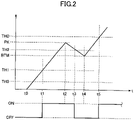
- FIG. 2 is a diagram showing an example of the relationship between a pressing force of the touch operation performed on the operating surface 101A and the thresholds the press identifying part 143 uses to determine whether the operating part is ON or OFF.
- the horizontal axis is a time axis t. Below the horizontal axis, the results (ON and OFF) determined by the press identifying part 143 are shown.
- the vertical axis of FIG. 2 shows a first threshold TH1, a second threshold TH2, and a predetermined threshold THD, and shows, in addition, a threshold TH0, a peak value PK, and a bottom value BTM.
- the first threshold TH1 is the threshold for use when switching the operating part from OFF mode to ON mode. If the pressing force surpasses the first threshold TH1 while the operating part is OFF, the press identifying part 143 determines that the operating part is turned ON. This is when the operating part is turned ON for the first time by the touch operation.
- the first threshold TH1 is used, for example, when the user presses the operating surface 101A and performs the touch operation for selecting an operating part.
- the press identifying part 143 determines that the pressing force surpasses the first threshold TH1 and an operating part is turned ON, the operating part is selected. Note that, even when the operating part is turned ON for the first time and then turned OFF later, the HMI processing part 144 keeps the state in which the operating part is selected, as long as the pressing force is greater than the first threshold TH1.
- the peak value PK is the peak value of pressing force to be detected by the press identifying part 143 after the operating part switches from OFF mode to ON mode. After the operating part switches from OFF mode to ON mode, the press identifying part 143 monitors the pressing force and detects the peak value (maximum value) of the pressing force. The press identifying part 143 stores the detected peak value PK in the memory 145.
- the second threshold TH2 is the threshold for use to determine whether the operating part is switched from ON to OFF.
- the second threshold TH2 is set to a predetermined proportion of the peak value PK (proportion expressed as a percentage smaller than 100%) by the press identifying part 143.
- the predetermined proportion is set to 70% to 85%, for example.
- the bottom value BTM is the minimum value of the pressing force at that time.
- the bottom value BTM is detected within a predetermined period of time after the pressing force equals or falls below the second threshold TH2.
- the limitation " within a predetermined period of time” is provided because, after an operating part is selected and gives the first ON, the second ON to confirm the operating part's selection is likely to come at an early stage after the first ON.
- the bottom value BTM of the pressing force is the minimum value produced before the user presses on the operating part again to confirm the selection of this operating part.
- the bottom value BTM is a value less than or equal to the second threshold TH2 and greater than the first threshold TH1. This is because the selection of the operating part is cancelled OFF by the HMI processing part 144 if the pressing force equals or falls below the first threshold TH1.
- the bottom value BTM is detected by the press identifying part 143 and stored in the memory 145.
- the predetermined threshold THD is the threshold for use when the pressing force drops from the peak value PK and equals or falls below the second threshold TH2 while the operating part is ON, the operating part switches from ON to OFF, the pressing force increases again after reaching the bottom value BTM, and then the operating part switches from OFF to ON again. This is when the operating part is turned ON for the second time by the touch operation after the first ON.
- the predetermined threshold THD is a value set by the press identifying part 143 based on the bottom value BTM, and is, for example, the value adding a predetermined proportion of the bottom value BTM to the bottom value BTM, or the value adding a threshold (an example of a third threshold) to the bottom value BTM.
- the predetermined proportion may be set to, for example, approximately 40% to 60%.
- the threshold to add to the bottom value BTM may be set to, for example, approximately 40% to 60% of the bottom value BTM, or a real value may be provided in advance and used.
- the threshold TH0 is the threshold for use to determine whether or not a touch operation is performed on the operating surface 101A. Here, whether or not a touch operation is performed is determined by the press identifying part 143, for example. Note that the threshold TH0 may be, for example, about half of the first threshold TH1.
- the press identifying part 143 determines that the operating part is switched from OFF to ON. While the pressing force keeps increasing, the press identifying part 143 keeps monitoring the pressing force and detects the peak value PK at a time t2. Upon detecting the peak value PK, the press identifying part 143 calculates the second threshold TH2.
- the press identifying part 143 determines that the operating part is switched from ON to OFF.
- the pressing force keeps dropping, and the press identifying part 143 keeps monitoring the pressing force and detects the bottom value BTM at a time t4.
- the press identifying part 143 calculates a predetermined threshold THD.
- the pressing force increases again after reaching the bottom value BTM, and, when the pressing force surpasses the predetermined threshold THD at a time t5, the press identifying part 143 determines that the operating part is switched from OFF to ON.
- the pressing force surpasses the predetermined threshold THD, which is set by the press identifying part 143 based on the bottom value BTM, without equaling or falling below the first threshold TH1, and therefore the press identifying part 143 determines that the operating part is switched from OFF to ON. This is the second on.
- the operating part is turned ON again while still being selected, so that the operation of selecting this operating part is confirmed.
- FIG. 3 is a diagram showing a flowchart of an embodiment of the process executed in the press identifying part 143.
- the process shown in the flowchart of FIG. 3 is a process in an input check method according to an embodiment.
- step S1 determines whether or not the pressing force is greater than the first threshold TH1 (step S1).
- step S1: NO the press identifying part 143 determines that the pressing force does not surpass the first threshold TH1 (S1: NO)
- step S1 the process of step S1 is repeated until the pressing force is determined to be greater than the first threshold TH1 (S1: YES).
- the press identifying part 143 determines that the operating part is switched from OFF to ON (step S2). This is the first ON.
- the HMI processing part 144 places the operating part in a state in which it is selected.
- Step S3 is a subroutine process, in which, after the operating part switches from OFF mode to ON mode, the press identifying part 143 monitors the pressing force, thereby detecting the peak value (maximum value) of the pressing force. Note that the press identifying part 143 stores the detected peak value PK in the memory 145.
- the press identifying part 143 determines whether or not the pressing force is less than or equal to the second threshold TH2 (step S4). The press identifying part 143 repeats the process of step S4 until the pressing force equals or falls below the second threshold TH2.
- the press identifying part 143 determines that the pressing force is less than or equal to the second threshold TH2 (S4: YES)
- the press identifying part 143 determines that the operating part is switched from ON to OFF (step S5).
- the HMI processing part 144 keeps the operating part in the state in which it is selected.
- Step S6 is a subroutine process, in which the press identifying part 143 monitors the pressing force, thereby detecting the peak value of the pressing force.
- the press identifying part 143 determines whether or not the pressing force is greater than the predetermined threshold THD (step S7).
- step S8 determines that the pressing force is greater than the predetermined threshold THD (S7: YES)
- the press identifying part 143 determines that the operating part is turned ON (step S8). Since this is the second ON, the HMI processing part 144 confirms the selection of the operating part.
- step S8 the press identifying part 143 returns to step S3 of the flow to check the operations after the second ON.
- the press identifying part 143 determines whether or not the pressing force is less than or equal to the first threshold TH1 (step S9). This process of determining whether or not the pressing force is less than or equal to the first threshold TH1 is provided because there are cases where the pressing force is less than or equal to the predetermined threshold THD and the operation for the second ON is not performed.
- the press identifying part 143 determines that the pressing force is less than or equal to the first threshold TH1 (S9: YES)
- the press identifying part 143 determines that the operating part is turned OFF (step S10).
- the HMI processing part 144 places the operating part in a state in which it is not selected. The above done, the series of processes is finished (end).
- step S9 determines in step S9 that the pressing force is not less than or equal to the first threshold TH1 (S9: NO)
- the press identifying part 143 returns to step S7 of the flow, to determine whether the pressing force is greater than the predetermined threshold THD.
- an operating part is turned ON for the first time when the pressing force surpasses the first threshold TH1, the operating part switches from ON to OFF when the pressing force drops from the peak value PK and equals or falls below the second threshold TH2 while the operating part is ON, and the operating part is turned ON for the second time when the pressing force reaches the bottom value BTM and surpasses the predetermined threshold THD.
- the second ON can be identified at an early stage.
- the HMI processing part 144 can confirm the selection of the operating part at an early stage based on the result of ON/OFF check in the press identifying part 143 and the position identified by the position identifying part 141 as where the touch operation is performed.
- the press identifying part 143 determines that the operating part is turned ON when the pressing force surpasses the first threshold TH1 while the operating part is OFF, determines that the operating part is switched from ON to OFF when the pressing force surpasses the first threshold TH1 and then equals or falls below the second threshold TH2, and, after thus determining that the operating part is switched from ON to OFF, detects the bottom value BTM of the pressing force, so that, when the pressing force drops after the first ON and starts rising towards the second ON, the press identifying part 143 can detect the bottom value then as the bottom value BTM.
- the bottom value BTM is a value that is less than or equal to the second threshold TH2 and that is greater than the first threshold TH1, it is possible to identify the second ON at an earlier stage.
- the press check part 143 determines that the operating part is switched from OFF to ON, so that, when, following the first ON, the operation for the second ON is performed successively, it is possible to identify the second ON.
- the predetermined threshold THD is the value adding a predetermined proportion to the bottom value BTM, or the value adding a threshold to the bottom value BTM, so that the predetermined threshold THD for identifying the second ON can be generated based on the bottom value BTM detected, and the second ON can be executed, at an early stage, depending on the pressing force. Consequently, it is possible to provide an input check device 100A and electrical equipment 100 having even better operability, as well as an input check method.
Landscapes
- Engineering & Computer Science (AREA)
- General Engineering & Computer Science (AREA)
- Theoretical Computer Science (AREA)
- Human Computer Interaction (AREA)
- Physics & Mathematics (AREA)
- General Physics & Mathematics (AREA)
- Position Input By Displaying (AREA)
- User Interface Of Digital Computer (AREA)
Abstract
Description
- The disclosure herein relates to an input check device and an input check method.
- Conventionally, there is electrical equipment including an operating part that accepts inputs from the operator, a contact detection part that detects contacts on the operating part, a piezoelectric element that detects changes of pressure loads on the operating part, and a control part that executes a first process when the piezoelectric element detects a change with the first pressure load, and, in this electrical equipment, when the piezoelectric element detects a change with a second pressure load and the contact detection part keeps detecting contacts after the first pressure load is detected until the second pressure load is detected, the control part executes a second process. The amount of change with the second pressure load is less than or equal to the amount of change with the first pressure load. The input of the first pressure load is what is commonly referred to as a "half-press," and the input of the second pressure load is what is commonly referred to as a "full press" (see, for example, patent document 1) .
- [Patent Document 1]: International Publication No.
WO2017-122466A1 - Now, there are input methods in which an input operation is performed once and performed again later, instead of input methods to use pressure loads that vary significantly such as a half-press and a full-press. For example, there is an input method in which the first input operation to perform is an operation for selecting an operating part, and in which the second input operation is performed with the same pressure load as that of the first input operation to confirm the content of the selection made in the first input operation.
- With such an input method, after the first input operation triggers "ON," if the threshold for identifying "OFF" is the same as the threshold for determining whether the first input operation resulted in "ON," it is then necessary to wait until the pressure load of the first input operation drops, which makes it slow to identify "OFF." Taking time to identify "OFF" leads to poor operability.
- It is therefore a general object of the present disclosure to provide an input check device having excellent operability, and an input check method.
- The invention relates to an input check device and method according to the appended claims. Embodiments are disclosed in the dependent claims.
- An input check device according to at least one embodiment of the present disclosure includes a coordinate detection part configured to detect coordinates of a touch operation a user performs on an operating surface when operating an operating part through the operating surface, a pressing force detection part configured to detect a pressing force of the touch operation, and an identifying part configured to determine whether the operating part is ON or OFF based on the pressing force detected in the pressing force detection part, and, in this input check device, after determining that the operating part is switched from ON mode to OFF mode, the identifying part detects a minimum value of the pressing force, and when, following the detection of the minimum value, the pressing force surpasses a predetermined threshold, the predetermined threshold being set based on the minimum value and being greater than the minimum value, the identifying part determines that the operating part is switched from OFF to ON.
- According to the present disclosure, it is possible to provide an input check device having excellent operability, and an input check method.
-
-
FIG. 1 is a diagram showingelectrical equipment 100 according to an embodiment; -
FIG. 2 is a diagram showing an example of the relationship between a pressing force of a touch operation performed on an operating surface 101A, and the thresholds apress identifying part 143 uses to determine whether an operating part is ON or OFF; and -
FIG. 3 is a diagram showing a flowchart of an embodiment of a process executed in thepress identifying part 143. - Now, embodiments for carrying out the input check device and input check method according to the present disclosure will be described below with reference to the accompanying drawings.
-
FIG. 1 is a diagram showingelectrical equipment 100 according to an embodiment. Theelectrical equipment 100 includes ahousing 101, atouch panel 110, adisplay panel 120, a pressingforce detection part 130, and acontrol device 140. Thetouch panel 110 is an example of a coordinate detection part, and thedisplay panel 120 is an example of a display part. - With the present embodiment, the portion of the
electrical equipment 100 excluding thehousing 101 constitutes theinput check device 100A. Therefore, thetouch panel 110, thedisplay panel 120, the pressingforce detection part 130, and thecontrol device 140, which are included in theinput check device 100A, are marked with the reference sign of theinput check device 100A in parentheses. Furthermore, the method executed on theinput check device 100A is the input check method according to the embodiment. Note that theinput check device 100A may include thehousing 101. - In the following description, the XYZ coordinate system will be defined and described, in which the direction parallel to the X axis (X direction), the direction parallel to the Y axis (Y direction), and the direction parallel to the Z axis (Z direction) are orthogonal to each other. Also, in the following description, the -Z direction side may be referred to with words such as "the lower side," "below," and so forth, and the +Z direction side may be referred to with words such as "the upper side," "above," and so forth, but this is only for ease of explanation, and does not refer to the general concept of up and down. Also, a plan view means a view in the X-Y plane. Furthermore, in the following description, each component may be shown in exaggerated length, thickness, breadth, and so forth, for ease of understanding of the configuration.
- The
housing 101 includes an operating surface 101A, and accommodates thetouch panel 110, thedisplay panel 120, the pressingforce detection part 130, and thecontrol device 140. Thehousing 101 is made of resin, for example. The operating surface 101A is the surface of a transparent plate located above thetouch panel 110. The transparent plate is made of glass or resin, for example. - In
FIG. 1 , the thickness of thehousing 101 in the Z direction is exaggerated. The operating surface 101A is parallel to the XY plane. In this one example, thetouch panel 110, thedisplay panel 120, and the pressingforce detection part 130 are provided in this order from the operating surface 101A downward. Note that the order in which thetouch panel 110, thedisplay panel 120, and the pressingforce detection part 130 are provided is not limited to this. - For example, the
electrical equipment 100 detects, in thetouch panel 110, the coordinates of a touch operation the user performs on the operating surface 101A, detects the pressing force of the touch operation in the pressingforce detection part 130, accepts a touch operation on an operating part, which thecontrol device 140 shows on thedisplay panel 120 in a GUI (Graphic User Interface), based on the coordinates detected on thetouch panel 110 and the pressing force detected in the pressingforce detection part 130, and controls the display on thedisplay panel 120 based on the content of the operation. The operating part, according to the present embodiment, may be an image of an operating icon, an image of an operation menu, an image of an operation switch, and so forth shown on thedisplay panel 120. A touch operation is an input operation the user perform by touching the operating surface 101A with his/her fingertip FT, and is an input operation whereby the user operates the operating part via the operating surface 101A. Furthermore, thecontrol device 140 may control the display on thedisplay panel 120 based on the content of operation, and, furthermore, output control signals for controlling theelectrical equipment 100 as the control target that serves as the user's input part. - The
electrical equipment 100 is equipment that can be mounted on a vehicle, for example, and that can be used as an HMI (Human Machine Interface). In this case, the equipment to be the target of control may be, for example, a variety of equipment such as the navigation system, the audio system, and the air conditioner that are mounted on the vehicle. The control signals output from thecontrol device 140 are, for example, signals for operating these equipments. - In this an example, the
touch panel 110 is a capacitive touch panel and detects the coordinates to show the position of the fingertip FT of the user's hand or the like, touching on the operating surface 101A. Here, a case will be described as an example where the user touches the operating surface 101A with his/her fingertip FT to input operations. Note that thetouch panel 110 may be of a type other than the capacitive type, and may be, for example, a resistive-film type. - For the
display panel 120, for example, a liquid crystal display panel, an organic EL (Electroluminescence) display panel, and so forth can be used. Thedisplay panel 120 can show images of operating parts of various equipment in the vehicle described above. For example, when audio equipment is the target of control, GUI images to represent the volume-control switch, the tune-selection switch, and so forth may serve as images of operating parts. - The pressing
force detection part 130 detects the pressing force of a touch operation performed on the operating surface 101A. The pressing force is the downward pressure load of the touch operation. For the pressingforce detection part 130, for example, a sensor using a piezo element, a sensor capable of detecting displacement, and so forth can be used. Note that the pressingforce detection part 130 may be a processing part that converts the area of the touch operation detected on thetouch panel 110 into a pressing force. The pressingforce detection part 130 is larger than thetouch panel 110 in a plan view. Aregion 130A, in which the pressing force can be detected, is larger than aregion 110A, in which the touch operation on thetouch panel 110 can be detected in a plan view, and includes theregion 110A. By this means, even when a touch operation is performed in an edge part of thetouch panel 110, the pressing force can still be detected. The relationship in size between the pressingforce detection part 130 and theregion 130A and thetouch panel 100 and theregion 110A is an example, and is by no means limiting. - The
control device 140 includes aposition identifying part 141, a pressingforce acquiring part 142, apress identifying part 143, anHMI processing part 144, and amemory 145. Thepress identifying part 143 is an example of an identifying part. Thecontrol device 140 is implemented using a computer including a CPU (Central Processing part), a RAM (Random Access Memory), a ROM (Read Only Memory), an HDD (Hard Disk Drive), an input/output interface, an internal bus, and so forth. - The
position identifying part 141, the pressingforce acquiring part 142, thepress identifying part 143, and theHMI processing part 144 are program functions that are executed on thecontrol device 140, and shown as functional blocks. Thememory 145 represents, functionally, the memory of thecontrol device 140. - The
position identifying part 141 applies a voltage to a number of electrodes that extend in the X direction of thetouch panel 110 and a number of electrodes that extend in the Y direction, in order, detects the capacitance at the intersections of the electrodes extending in the X direction and the electrodes extending in the Y direction, and identifies the position (coordinates) where the touch operation was performed. - The pressing
force acquiring part 142 acquires the pressing force detected in the pressingforce detection part 130, applies digital conversion processing and the like to it, and outputs the resulting data to thepress identifying part 143. - The
press identifying part 143 compares the data representing the pressing force, output from the pressingforce acquiring part 142, against a threshold, and determines whether or not the operating part is turned ON or OFF by the press of the touch operation. With the present embodiment, the state in which an operating part is touch-operated (pressed) with a pressing force greater than or equal to a threshold will be rephrased as "the operating part is (turned) ON." Meanwhile, the state in which the operating part is touch-operated (pressed) with a pressing force less than the threshold, or the state in which the touch operation is cancelled, will be rephrased as "the operating part is (turned) OFF." The process in thepress identifying part 143 will be described later with reference toFIG. 2 . - The
HMI processing part 144 controls the display on thedisplay panel 120 based on the position identified by theposition identifying part 141 as where the touch operation was performed, and the result determined by thepress identifying part 143. When the operating part is turned ON for the first time based on the result determined by thepress identifying part 143, theHMI processing part 144 places the operating part in a state in which it is selected. Furthermore, when the operating part is turned ON for the second time, the press identifying part sets up a state in which the selection is confirmed. - The
memory 145 stores the programs and data that theposition identifying part 141, the pressingforce acquiring part 142, thepress identifying part 143, and theHMI processing part 144 need to perform processes, as well as data generated by these processes. -
FIG. 2 is a diagram showing an example of the relationship between a pressing force of the touch operation performed on the operating surface 101A and the thresholds thepress identifying part 143 uses to determine whether the operating part is ON or OFF. InFIG. 2 , the horizontal axis is a time axis t. Below the horizontal axis, the results (ON and OFF) determined by thepress identifying part 143 are shown. Furthermore, the vertical axis ofFIG. 2 shows a first threshold TH1, a second threshold TH2, and a predetermined threshold THD, and shows, in addition, a threshold TH0, a peak value PK, and a bottom value BTM. - The first threshold TH1 is the threshold for use when switching the operating part from OFF mode to ON mode. If the pressing force surpasses the first threshold TH1 while the operating part is OFF, the
press identifying part 143 determines that the operating part is turned ON. This is when the operating part is turned ON for the first time by the touch operation. The first threshold TH1 is used, for example, when the user presses the operating surface 101A and performs the touch operation for selecting an operating part. When thepress identifying part 143 determines that the pressing force surpasses the first threshold TH1 and an operating part is turned ON, the operating part is selected. Note that, even when the operating part is turned ON for the first time and then turned OFF later, theHMI processing part 144 keeps the state in which the operating part is selected, as long as the pressing force is greater than the first threshold TH1. - The peak value PK is the peak value of pressing force to be detected by the
press identifying part 143 after the operating part switches from OFF mode to ON mode. After the operating part switches from OFF mode to ON mode, thepress identifying part 143 monitors the pressing force and detects the peak value (maximum value) of the pressing force. Thepress identifying part 143 stores the detected peak value PK in thememory 145. - Assuming that the pressing force drops from the peak value PK while the operating part is ON, the second threshold TH2 is the threshold for use to determine whether the operating part is switched from ON to OFF. The second threshold TH2 is set to a predetermined proportion of the peak value PK (proportion expressed as a percentage smaller than 100%) by the
press identifying part 143. The predetermined proportion is set to 70% to 85%, for example. When the pressing force drops from the peak value PK and equals or falls below the second threshold TH2 while the operating part is ON, thepress identifying part 143 determines that the operating part is switched from ON to OFF. - When the pressing force drops from the peak value PK and equals or falls below the second threshold TH2 while the operating part is ON and the operating part switches from ON to OFF, the bottom value BTM is the minimum value of the pressing force at that time. The bottom value BTM is detected within a predetermined period of time after the pressing force equals or falls below the second threshold TH2. The limitation " within a predetermined period of time" is provided because, after an operating part is selected and gives the first ON, the second ON to confirm the operating part's selection is likely to come at an early stage after the first ON. Assuming the state in which the user softens his/her pressing force while still selecting (touching on) an operating part, the bottom value BTM of the pressing force is the minimum value produced before the user presses on the operating part again to confirm the selection of this operating part. The bottom value BTM is a value less than or equal to the second threshold TH2 and greater than the first threshold TH1. This is because the selection of the operating part is cancelled OFF by the
HMI processing part 144 if the pressing force equals or falls below the first threshold TH1. The bottom value BTM is detected by thepress identifying part 143 and stored in thememory 145. - The predetermined threshold THD is the threshold for use when the pressing force drops from the peak value PK and equals or falls below the second threshold TH2 while the operating part is ON, the operating part switches from ON to OFF, the pressing force increases again after reaching the bottom value BTM, and then the operating part switches from OFF to ON again. This is when the operating part is turned ON for the second time by the touch operation after the first ON. The predetermined threshold THD is a value set by the
press identifying part 143 based on the bottom value BTM, and is, for example, the value adding a predetermined proportion of the bottom value BTM to the bottom value BTM, or the value adding a threshold (an example of a third threshold) to the bottom value BTM. The predetermined proportion may be set to, for example, approximately 40% to 60%. The threshold to add to the bottom value BTM may be set to, for example, approximately 40% to 60% of the bottom value BTM, or a real value may be provided in advance and used. - The threshold TH0 is the threshold for use to determine whether or not a touch operation is performed on the operating surface 101A. Here, whether or not a touch operation is performed is determined by the
press identifying part 143, for example. Note that the threshold TH0 may be, for example, about half of the first threshold TH1. - As shown in
FIG. 2 , when the pressing force rises at a time t0 and surpasses the first threshold TH1 at a time t1, thepress identifying part 143 determines that the operating part is switched from OFF to ON. While the pressing force keeps increasing, thepress identifying part 143 keeps monitoring the pressing force and detects the peak value PK at a time t2. Upon detecting the peak value PK, thepress identifying part 143 calculates the second threshold TH2. - When the pressing force drops after time t2 and equals or falls below the second threshold TH2 at a time t3, the
press identifying part 143 determines that the operating part is switched from ON to OFF. The pressing force keeps dropping, and thepress identifying part 143 keeps monitoring the pressing force and detects the bottom value BTM at a time t4. Upon detecting the bottom value BTM, thepress identifying part 143 calculates a predetermined threshold THD. - The pressing force increases again after reaching the bottom value BTM, and, when the pressing force surpasses the predetermined threshold THD at a time t5, the
press identifying part 143 determines that the operating part is switched from OFF to ON. After the operating part is turned ON at time t1 and turned OFF at time t3, the pressing force surpasses the predetermined threshold THD, which is set by thepress identifying part 143 based on the bottom value BTM, without equaling or falling below the first threshold TH1, and therefore thepress identifying part 143 determines that the operating part is switched from OFF to ON. This is the second on. The operating part is turned ON again while still being selected, so that the operation of selecting this operating part is confirmed. -
FIG. 3 is a diagram showing a flowchart of an embodiment of the process executed in thepress identifying part 143. The process shown in the flowchart ofFIG. 3 is a process in an input check method according to an embodiment. - When the process starts, the
press identifying part 143 determines whether or not the pressing force is greater than the first threshold TH1 (step S1). When thepress identifying part 143 determines that the pressing force does not surpass the first threshold TH1 (S1: NO), the process of step S1 is repeated until the pressing force is determined to be greater than the first threshold TH1 (S1: YES). - When determining that the pressing force is greater than the first threshold TH1 (S1: YES), the
press identifying part 143 determines that the operating part is switched from OFF to ON (step S2). This is the first ON. Upon the first ON, theHMI processing part 144 places the operating part in a state in which it is selected. - The
press identifying part 143 starts the detection of the peak value PK of the pressing force (step S3). Step S3 is a subroutine process, in which, after the operating part switches from OFF mode to ON mode, thepress identifying part 143 monitors the pressing force, thereby detecting the peak value (maximum value) of the pressing force. Note that thepress identifying part 143 stores the detected peak value PK in thememory 145. - Upon detecting the pressing force peak value PK, the
press identifying part 143 determines whether or not the pressing force is less than or equal to the second threshold TH2 (step S4). Thepress identifying part 143 repeats the process of step S4 until the pressing force equals or falls below the second threshold TH2. - When the
press identifying part 143 determines that the pressing force is less than or equal to the second threshold TH2 (S4: YES), thepress identifying part 143 determines that the operating part is switched from ON to OFF (step S5). When doing this, theHMI processing part 144 keeps the operating part in the state in which it is selected. - The
press identifying part 143 starts the detection of the bottom value BTM (step S6). Step S6 is a subroutine process, in which thepress identifying part 143 monitors the pressing force, thereby detecting the peak value of the pressing force. - The
press identifying part 143 determines whether or not the pressing force is greater than the predetermined threshold THD (step S7). - When the
press identifying part 143 determines in step S7 that the pressing force is greater than the predetermined threshold THD (S7: YES), thepress identifying part 143 determines that the operating part is turned ON (step S8). Since this is the second ON, theHMI processing part 144 confirms the selection of the operating part. When the process of step S8 is finished, thepress identifying part 143 returns to step S3 of the flow to check the operations after the second ON. - Also, when the
press identifying part 143 determines that the pressing force does not surpass than the predetermined threshold THD (S7: NO), thepress identifying part 143 determines whether or not the pressing force is less than or equal to the first threshold TH1 (step S9). This process of determining whether or not the pressing force is less than or equal to the first threshold TH1 is provided because there are cases where the pressing force is less than or equal to the predetermined threshold THD and the operation for the second ON is not performed. - When the
press identifying part 143 determines that the pressing force is less than or equal to the first threshold TH1 (S9: YES), thepress identifying part 143 determines that the operating part is turned OFF (step S10). As a result of this, theHMI processing part 144 places the operating part in a state in which it is not selected. The above done, the series of processes is finished (end). - Furthermore, when the
press identifying part 143 determines in step S9 that the pressing force is not less than or equal to the first threshold TH1 (S9: NO), thepress identifying part 143 returns to step S7 of the flow, to determine whether the pressing force is greater than the predetermined threshold THD. - As described above, with the
electrical equipment 100 and theinput check device 100A, an operating part is turned ON for the first time when the pressing force surpasses the first threshold TH1, the operating part switches from ON to OFF when the pressing force drops from the peak value PK and equals or falls below the second threshold TH2 while the operating part is ON, and the operating part is turned ON for the second time when the pressing force reaches the bottom value BTM and surpasses the predetermined threshold THD. In this way, the second ON can be identified at an early stage. - Therefore, it is possible to provide an
input check device 100A andelectrical equipment 100 having excellent operability, as well as an input check method. As a result of this, theHMI processing part 144 can confirm the selection of the operating part at an early stage based on the result of ON/OFF check in thepress identifying part 143 and the position identified by theposition identifying part 141 as where the touch operation is performed. - Furthermore, the
press identifying part 143 determines that the operating part is turned ON when the pressing force surpasses the first threshold TH1 while the operating part is OFF, determines that the operating part is switched from ON to OFF when the pressing force surpasses the first threshold TH1 and then equals or falls below the second threshold TH2, and, after thus determining that the operating part is switched from ON to OFF, detects the bottom value BTM of the pressing force, so that, when the pressing force drops after the first ON and starts rising towards the second ON, thepress identifying part 143 can detect the bottom value then as the bottom value BTM. - Furthermore, since the bottom value BTM is a value that is less than or equal to the second threshold TH2 and that is greater than the first threshold TH1, it is possible to identify the second ON at an earlier stage.
- Furthermore, when the pressing force surpasses the first threshold TH1 and equals or falls below the second threshold TH2, the pressing force's bottom value BTM is detected before the pressing force equals or falls below the first threshold TH1, and the pressing force surpasses a predetermined threshold THD, the
press check part 143 determines that the operating part is switched from OFF to ON, so that, when, following the first ON, the operation for the second ON is performed successively, it is possible to identify the second ON. - Furthermore, the predetermined threshold THD is the value adding a predetermined proportion to the bottom value BTM, or the value adding a threshold to the bottom value BTM, so that the predetermined threshold THD for identifying the second ON can be generated based on the bottom value BTM detected, and the second ON can be executed, at an early stage, depending on the pressing force. Consequently, it is possible to provide an
input check device 100A andelectrical equipment 100 having even better operability, as well as an input check method. - Although embodiments of the input check device and input check according to the present disclosure have been described above by way of example, the specific embodiments of the disclosure herein are by no means limiting, and various modifications and changes can be made without departing from the scope of the herein-contained claims.
- This application is based on and claims priority to
Japanese Patent Application No. 2021-068345, filed on April 14, 2021 -
- 100
- Electrical equipment
- 101A
- Operating surface
- 110
- Touch panel
- 120
- Display panel
- 130
- Pressing force detection part
- 140
- Control device
- 141
- Position identifying part
- 142
- Pressing force acquisition part
- 143
- Press identifying part
- 144
- HMI processing part
- 145
- Memory
Claims (6)
- An input check device comprising:a coordinate detection part configured to detect coordinates of a touch operation a user performs on an operating surface when operating an operating part through the operating surface;a pressing force detection part configured to detect a pressing force of the touch operation; andan identifying part configured to determine whether the operating part is ON or OFF based on the pressing force detected in the pressing force detection part, wherein:after determining that the operating part is switched from ON mode to OFF mode, the identifying part is configured to detect a minimum value of the pressing force; andthe identifying part is configured to determine that the operating part is switched from OFF to ON when, following the detection of the minimum value, the pressing force surpasses a predetermined threshold that is set based on the minimum value and that is greater than the minimum value.
- The input check device according to claim 1, wherein:when the pressing force surpasses a first threshold while the operating part is OFF, the identifying part is configured to determine that the operating part is turned ON;when the pressing force surpasses the first threshold and becomes equal to or less than a second threshold, the second threshold being higher than the first threshold and being a predetermined proportion of a peak value of the pressing force, the identifying part is configured to determine that the operating part is switched from ON to OFF; andafter determining that the operating part is switched from ON to OFF, the identifying part is configured to detect the minimum value of the pressing force.
- The input check device according to claim 2, wherein the minimum value is a value that is less than or equal to the second threshold, and that is greater than the first threshold.
- The input check device according to claim 2 or 3, wherein, when the pressing force surpasses the predetermined threshold while the pressing force surpasses the first threshold and becomes equal to or less than the second threshold and the minimum value of the pressing force is detected without the pressing force becoming equal or less than the first threshold, the identifying part is configured to determine that the operating part is switched from OFF to ON.
- The input check device according to any one of claims 1 to 4, wherein the predetermined threshold is a value adding a predetermined proportion of the minimum value to the minimum value, or a value adding a third threshold to the minimum value.
- An input check method for an input check device, the input check device comprising:a coordinate detection part configured to detect coordinates of a touch operation a user performs on an operating surface when operating an operating part through the operating surface;a pressing force detection part configured to detect a pressing force of the touch operation; andan identifying part configured to determine whether the operating part is ON or OFF based on the pressing force detected in the pressing force detection part, the input check method comprising the steps of:after determining that the operating part is switched from ON mode to OFF mode, detecting a minimum value of the pressing force; anddetermining that the operating part is switched from OFF to ON when, following the detection of the minimum value, the pressing force surpasses a predetermined threshold that is set based on the minimum value and that is greater than the minimum value.
Applications Claiming Priority (1)
| Application Number | Priority Date | Filing Date | Title |
|---|---|---|---|
| JP2021068345A JP7854268B2 (en) | 2021-04-14 | 2021-04-14 | Input determination device and input determination method |
Publications (2)
| Publication Number | Publication Date |
|---|---|
| EP4075248A1 true EP4075248A1 (en) | 2022-10-19 |
| EP4075248B1 EP4075248B1 (en) | 2024-08-14 |
Family
ID=80999330
Family Applications (1)
| Application Number | Title | Priority Date | Filing Date |
|---|---|---|---|
| EP22165132.6A Active EP4075248B1 (en) | 2021-04-14 | 2022-03-29 | Input check device and input check method |
Country Status (4)
| Country | Link |
|---|---|
| US (1) | US11868577B2 (en) |
| EP (1) | EP4075248B1 (en) |
| JP (1) | JP7854268B2 (en) |
| CN (1) | CN115268680A (en) |
Citations (4)
| Publication number | Priority date | Publication date | Assignee | Title |
|---|---|---|---|---|
| US20130265273A1 (en) * | 2012-04-10 | 2013-10-10 | Cleankeys Inc. | Systems and methods for detecting a press on a touch-sensitive surface |
| WO2017122466A1 (en) | 2016-01-12 | 2017-07-20 | 株式会社村田製作所 | Electronic apparatus |
| US20210064157A1 (en) * | 2019-08-28 | 2021-03-04 | Lenovo (Singapore) Pte. Ltd. | Systems, apparatus, and methods for detecting computing device inputs by a pointing body |
| JP2021068345A (en) | 2019-10-28 | 2021-04-30 | ファナック株式会社 | Numerical controller |
Family Cites Families (12)
| Publication number | Priority date | Publication date | Assignee | Title |
|---|---|---|---|---|
| KR20100018883A (en) * | 2008-08-07 | 2010-02-18 | 디케이 유아이엘 주식회사 | Method and system for user interface on electronic device |
| JP2012027875A (en) | 2010-07-28 | 2012-02-09 | Sony Corp | Electronic apparatus, processing method and program |
| US9696805B2 (en) | 2011-06-28 | 2017-07-04 | Kyocera Corporation | Electronic device |
| JP5845073B2 (en) * | 2011-12-07 | 2016-01-20 | アルパイン株式会社 | Information processing device |
| US9134807B2 (en) | 2012-03-02 | 2015-09-15 | Microsoft Technology Licensing, Llc | Pressure sensitive key normalization |
| US9864507B2 (en) | 2013-09-26 | 2018-01-09 | Synaptics Incorporated | Methods and apparatus for click detection on a force pad using dynamic thresholds |
| US10175833B2 (en) * | 2015-06-18 | 2019-01-08 | Synaptics Incorporated | Adaptive force sensing |
| CN105045454B (en) * | 2015-08-27 | 2017-10-17 | 广东欧珀移动通信有限公司 | A terminal false touch prevention method and terminal |
| KR102413108B1 (en) * | 2015-12-08 | 2022-06-27 | 삼성전자주식회사 | Method and electronic device for recognizing touch |
| CN105677090A (en) * | 2015-12-31 | 2016-06-15 | 宇龙计算机通信科技(深圳)有限公司 | Press control method and device |
| JP6770718B2 (en) | 2017-03-21 | 2020-10-21 | 株式会社東海理化電機製作所 | Tactile presentation device |
| CN110266876B (en) * | 2019-04-29 | 2020-12-29 | 努比亚技术有限公司 | Pressure threshold determination method and device and computer readable storage medium |
-
2021
- 2021-04-14 JP JP2021068345A patent/JP7854268B2/en active Active
-
2022
- 2022-03-29 EP EP22165132.6A patent/EP4075248B1/en active Active
- 2022-04-05 US US17/657,980 patent/US11868577B2/en active Active
- 2022-04-13 CN CN202210385042.6A patent/CN115268680A/en active Pending
Patent Citations (4)
| Publication number | Priority date | Publication date | Assignee | Title |
|---|---|---|---|---|
| US20130265273A1 (en) * | 2012-04-10 | 2013-10-10 | Cleankeys Inc. | Systems and methods for detecting a press on a touch-sensitive surface |
| WO2017122466A1 (en) | 2016-01-12 | 2017-07-20 | 株式会社村田製作所 | Electronic apparatus |
| US20210064157A1 (en) * | 2019-08-28 | 2021-03-04 | Lenovo (Singapore) Pte. Ltd. | Systems, apparatus, and methods for detecting computing device inputs by a pointing body |
| JP2021068345A (en) | 2019-10-28 | 2021-04-30 | ファナック株式会社 | Numerical controller |
Also Published As
| Publication number | Publication date |
|---|---|
| CN115268680A (en) | 2022-11-01 |
| JP7854268B2 (en) | 2026-05-01 |
| JP2022163424A (en) | 2022-10-26 |
| EP4075248B1 (en) | 2024-08-14 |
| US11868577B2 (en) | 2024-01-09 |
| US20220334681A1 (en) | 2022-10-20 |
Similar Documents
| Publication | Publication Date | Title |
|---|---|---|
| US10545659B2 (en) | Method for operating an operator control device of a motor vehicle in multi-finger operation | |
| JP2012247960A (en) | Information processing apparatus, information processing method, and computer program | |
| CN114270299B (en) | Touch panel device, operation recognition method, and recording medium having operation recognition program recorded thereon | |
| JP2007156634A (en) | Input device | |
| JPWO2012111227A1 (en) | Touch-type input device, electronic apparatus, and input method | |
| EP4075248B1 (en) | Input check device and input check method | |
| US9898106B2 (en) | Information processing system, information processing apparatus, and information processing method | |
| JP2000284912A (en) | Touch panel input computer | |
| JP2008165575A (en) | Touch panel device | |
| US9645655B2 (en) | Integrated touchpad and keyboard | |
| US11880525B2 (en) | Method and device for selecting input fields displayed on a screen and/or for activating input content displayed in a selected input field on the screen by means of manual inputs | |
| US20020126098A1 (en) | Input device capable of generating different input signals on single operating surface | |
| US20210089163A1 (en) | Touch device and operation method thereof | |
| JP2019101876A (en) | Input device, input control device, operated device, and program | |
| US12585368B2 (en) | Input display device | |
| JP2021182446A (en) | Input device and electronic apparatus including the same | |
| US20180292924A1 (en) | Input processing apparatus | |
| JP7622342B2 (en) | Input operation device | |
| JP2015011610A (en) | Button combination type touch panel input device | |
| JP4465231B2 (en) | Input device | |
| JP2018092317A (en) | Operation input device | |
| CN108733224A (en) | Numerical control device | |
| CN121326159A (en) | Touch device control method and touch device | |
| JP2016218820A (en) | Operation detection device | |
| WO2019082296A1 (en) | Computer operation command system |
Legal Events
| Date | Code | Title | Description |
|---|---|---|---|
| PUAI | Public reference made under article 153(3) epc to a published international application that has entered the european phase |
Free format text: ORIGINAL CODE: 0009012 |
|
| STAA | Information on the status of an ep patent application or granted ep patent |
Free format text: STATUS: THE APPLICATION HAS BEEN PUBLISHED |
|
| AK | Designated contracting states |
Kind code of ref document: A1 Designated state(s): AL AT BE BG CH CY CZ DE DK EE ES FI FR GB GR HR HU IE IS IT LI LT LU LV MC MK MT NL NO PL PT RO RS SE SI SK SM TR |
|
| STAA | Information on the status of an ep patent application or granted ep patent |
Free format text: STATUS: REQUEST FOR EXAMINATION WAS MADE |
|
| 17P | Request for examination filed |
Effective date: 20230330 |
|
| RBV | Designated contracting states (corrected) |
Designated state(s): AL AT BE BG CH CY CZ DE DK EE ES FI FR GB GR HR HU IE IS IT LI LT LU LV MC MK MT NL NO PL PT RO RS SE SI SK SM TR |
|
| GRAP | Despatch of communication of intention to grant a patent |
Free format text: ORIGINAL CODE: EPIDOSNIGR1 |
|
| STAA | Information on the status of an ep patent application or granted ep patent |
Free format text: STATUS: GRANT OF PATENT IS INTENDED |
|
| INTG | Intention to grant announced |
Effective date: 20240321 |
|
| GRAS | Grant fee paid |
Free format text: ORIGINAL CODE: EPIDOSNIGR3 |
|
| GRAA | (expected) grant |
Free format text: ORIGINAL CODE: 0009210 |
|
| STAA | Information on the status of an ep patent application or granted ep patent |
Free format text: STATUS: THE PATENT HAS BEEN GRANTED |
|
| AK | Designated contracting states |
Kind code of ref document: B1 Designated state(s): AL AT BE BG CH CY CZ DE DK EE ES FI FR GB GR HR HU IE IS IT LI LT LU LV MC MK MT NL NO PL PT RO RS SE SI SK SM TR |
|
| REG | Reference to a national code |
Ref country code: GB Ref legal event code: FG4D |
|
| REG | Reference to a national code |
Ref country code: CH Ref legal event code: EP |
|
| P01 | Opt-out of the competence of the unified patent court (upc) registered |
Free format text: CASE NUMBER: APP_41578/2024 Effective date: 20240715 |
|
| REG | Reference to a national code |
Ref country code: DE Ref legal event code: R096 Ref document number: 602022005257 Country of ref document: DE |
|
| REG | Reference to a national code |
Ref country code: IE Ref legal event code: FG4D |
|
| REG | Reference to a national code |
Ref country code: LT Ref legal event code: MG9D |
|
| REG | Reference to a national code |
Ref country code: NL Ref legal event code: MP Effective date: 20240814 |
|
| PG25 | Lapsed in a contracting state [announced via postgrant information from national office to epo] |
Ref country code: NO Free format text: LAPSE BECAUSE OF FAILURE TO SUBMIT A TRANSLATION OF THE DESCRIPTION OR TO PAY THE FEE WITHIN THE PRESCRIBED TIME-LIMIT Effective date: 20241114 |
|
| REG | Reference to a national code |
Ref country code: AT Ref legal event code: MK05 Ref document number: 1713918 Country of ref document: AT Kind code of ref document: T Effective date: 20240814 |
|
| PG25 | Lapsed in a contracting state [announced via postgrant information from national office to epo] |
Ref country code: NL Free format text: LAPSE BECAUSE OF FAILURE TO SUBMIT A TRANSLATION OF THE DESCRIPTION OR TO PAY THE FEE WITHIN THE PRESCRIBED TIME-LIMIT Effective date: 20240814 Ref country code: PL Free format text: LAPSE BECAUSE OF FAILURE TO SUBMIT A TRANSLATION OF THE DESCRIPTION OR TO PAY THE FEE WITHIN THE PRESCRIBED TIME-LIMIT Effective date: 20240814 Ref country code: GR Free format text: LAPSE BECAUSE OF FAILURE TO SUBMIT A TRANSLATION OF THE DESCRIPTION OR TO PAY THE FEE WITHIN THE PRESCRIBED TIME-LIMIT Effective date: 20241115 Ref country code: PT Free format text: LAPSE BECAUSE OF FAILURE TO SUBMIT A TRANSLATION OF THE DESCRIPTION OR TO PAY THE FEE WITHIN THE PRESCRIBED TIME-LIMIT Effective date: 20241216 Ref country code: FI Free format text: LAPSE BECAUSE OF FAILURE TO SUBMIT A TRANSLATION OF THE DESCRIPTION OR TO PAY THE FEE WITHIN THE PRESCRIBED TIME-LIMIT Effective date: 20240814 |
|
| PG25 | Lapsed in a contracting state [announced via postgrant information from national office to epo] |
Ref country code: BG Free format text: LAPSE BECAUSE OF FAILURE TO SUBMIT A TRANSLATION OF THE DESCRIPTION OR TO PAY THE FEE WITHIN THE PRESCRIBED TIME-LIMIT Effective date: 20240814 |
|
| PG25 | Lapsed in a contracting state [announced via postgrant information from national office to epo] |
Ref country code: LV Free format text: LAPSE BECAUSE OF FAILURE TO SUBMIT A TRANSLATION OF THE DESCRIPTION OR TO PAY THE FEE WITHIN THE PRESCRIBED TIME-LIMIT Effective date: 20240814 |
|
| PG25 | Lapsed in a contracting state [announced via postgrant information from national office to epo] |
Ref country code: IS Free format text: LAPSE BECAUSE OF FAILURE TO SUBMIT A TRANSLATION OF THE DESCRIPTION OR TO PAY THE FEE WITHIN THE PRESCRIBED TIME-LIMIT Effective date: 20241214 Ref country code: AT Free format text: LAPSE BECAUSE OF FAILURE TO SUBMIT A TRANSLATION OF THE DESCRIPTION OR TO PAY THE FEE WITHIN THE PRESCRIBED TIME-LIMIT Effective date: 20240814 |
|
| PG25 | Lapsed in a contracting state [announced via postgrant information from national office to epo] |
Ref country code: HR Free format text: LAPSE BECAUSE OF FAILURE TO SUBMIT A TRANSLATION OF THE DESCRIPTION OR TO PAY THE FEE WITHIN THE PRESCRIBED TIME-LIMIT Effective date: 20240814 |
|
| PG25 | Lapsed in a contracting state [announced via postgrant information from national office to epo] |
Ref country code: RS Free format text: LAPSE BECAUSE OF FAILURE TO SUBMIT A TRANSLATION OF THE DESCRIPTION OR TO PAY THE FEE WITHIN THE PRESCRIBED TIME-LIMIT Effective date: 20241114 Ref country code: ES Free format text: LAPSE BECAUSE OF FAILURE TO SUBMIT A TRANSLATION OF THE DESCRIPTION OR TO PAY THE FEE WITHIN THE PRESCRIBED TIME-LIMIT Effective date: 20240814 |
|
| PG25 | Lapsed in a contracting state [announced via postgrant information from national office to epo] |
Ref country code: RS Free format text: LAPSE BECAUSE OF FAILURE TO SUBMIT A TRANSLATION OF THE DESCRIPTION OR TO PAY THE FEE WITHIN THE PRESCRIBED TIME-LIMIT Effective date: 20241114 Ref country code: PT Free format text: LAPSE BECAUSE OF FAILURE TO SUBMIT A TRANSLATION OF THE DESCRIPTION OR TO PAY THE FEE WITHIN THE PRESCRIBED TIME-LIMIT Effective date: 20241216 Ref country code: PL Free format text: LAPSE BECAUSE OF FAILURE TO SUBMIT A TRANSLATION OF THE DESCRIPTION OR TO PAY THE FEE WITHIN THE PRESCRIBED TIME-LIMIT Effective date: 20240814 Ref country code: NO Free format text: LAPSE BECAUSE OF FAILURE TO SUBMIT A TRANSLATION OF THE DESCRIPTION OR TO PAY THE FEE WITHIN THE PRESCRIBED TIME-LIMIT Effective date: 20241114 Ref country code: NL Free format text: LAPSE BECAUSE OF FAILURE TO SUBMIT A TRANSLATION OF THE DESCRIPTION OR TO PAY THE FEE WITHIN THE PRESCRIBED TIME-LIMIT Effective date: 20240814 Ref country code: LV Free format text: LAPSE BECAUSE OF FAILURE TO SUBMIT A TRANSLATION OF THE DESCRIPTION OR TO PAY THE FEE WITHIN THE PRESCRIBED TIME-LIMIT Effective date: 20240814 Ref country code: IS Free format text: LAPSE BECAUSE OF FAILURE TO SUBMIT A TRANSLATION OF THE DESCRIPTION OR TO PAY THE FEE WITHIN THE PRESCRIBED TIME-LIMIT Effective date: 20241214 Ref country code: HR Free format text: LAPSE BECAUSE OF FAILURE TO SUBMIT A TRANSLATION OF THE DESCRIPTION OR TO PAY THE FEE WITHIN THE PRESCRIBED TIME-LIMIT Effective date: 20240814 Ref country code: GR Free format text: LAPSE BECAUSE OF FAILURE TO SUBMIT A TRANSLATION OF THE DESCRIPTION OR TO PAY THE FEE WITHIN THE PRESCRIBED TIME-LIMIT Effective date: 20241115 Ref country code: FI Free format text: LAPSE BECAUSE OF FAILURE TO SUBMIT A TRANSLATION OF THE DESCRIPTION OR TO PAY THE FEE WITHIN THE PRESCRIBED TIME-LIMIT Effective date: 20240814 Ref country code: ES Free format text: LAPSE BECAUSE OF FAILURE TO SUBMIT A TRANSLATION OF THE DESCRIPTION OR TO PAY THE FEE WITHIN THE PRESCRIBED TIME-LIMIT Effective date: 20240814 Ref country code: BG Free format text: LAPSE BECAUSE OF FAILURE TO SUBMIT A TRANSLATION OF THE DESCRIPTION OR TO PAY THE FEE WITHIN THE PRESCRIBED TIME-LIMIT Effective date: 20240814 Ref country code: AT Free format text: LAPSE BECAUSE OF FAILURE TO SUBMIT A TRANSLATION OF THE DESCRIPTION OR TO PAY THE FEE WITHIN THE PRESCRIBED TIME-LIMIT Effective date: 20240814 |
|
| PG25 | Lapsed in a contracting state [announced via postgrant information from national office to epo] |
Ref country code: DK Free format text: LAPSE BECAUSE OF FAILURE TO SUBMIT A TRANSLATION OF THE DESCRIPTION OR TO PAY THE FEE WITHIN THE PRESCRIBED TIME-LIMIT Effective date: 20240814 Ref country code: SM Free format text: LAPSE BECAUSE OF FAILURE TO SUBMIT A TRANSLATION OF THE DESCRIPTION OR TO PAY THE FEE WITHIN THE PRESCRIBED TIME-LIMIT Effective date: 20240814 Ref country code: RO Free format text: LAPSE BECAUSE OF FAILURE TO SUBMIT A TRANSLATION OF THE DESCRIPTION OR TO PAY THE FEE WITHIN THE PRESCRIBED TIME-LIMIT Effective date: 20240814 |
|
| PG25 | Lapsed in a contracting state [announced via postgrant information from national office to epo] |
Ref country code: EE Free format text: LAPSE BECAUSE OF FAILURE TO SUBMIT A TRANSLATION OF THE DESCRIPTION OR TO PAY THE FEE WITHIN THE PRESCRIBED TIME-LIMIT Effective date: 20240814 |
|
| PG25 | Lapsed in a contracting state [announced via postgrant information from national office to epo] |
Ref country code: CZ Free format text: LAPSE BECAUSE OF FAILURE TO SUBMIT A TRANSLATION OF THE DESCRIPTION OR TO PAY THE FEE WITHIN THE PRESCRIBED TIME-LIMIT Effective date: 20240814 |
|
| PG25 | Lapsed in a contracting state [announced via postgrant information from national office to epo] |
Ref country code: SK Free format text: LAPSE BECAUSE OF FAILURE TO SUBMIT A TRANSLATION OF THE DESCRIPTION OR TO PAY THE FEE WITHIN THE PRESCRIBED TIME-LIMIT Effective date: 20240814 Ref country code: IT Free format text: LAPSE BECAUSE OF FAILURE TO SUBMIT A TRANSLATION OF THE DESCRIPTION OR TO PAY THE FEE WITHIN THE PRESCRIBED TIME-LIMIT Effective date: 20240814 |
|
| REG | Reference to a national code |
Ref country code: DE Ref legal event code: R097 Ref document number: 602022005257 Country of ref document: DE |
|
| PLBE | No opposition filed within time limit |
Free format text: ORIGINAL CODE: 0009261 |
|
| STAA | Information on the status of an ep patent application or granted ep patent |
Free format text: STATUS: NO OPPOSITION FILED WITHIN TIME LIMIT |
|
| 26N | No opposition filed |
Effective date: 20250515 |
|
| PG25 | Lapsed in a contracting state [announced via postgrant information from national office to epo] |
Ref country code: SE Free format text: LAPSE BECAUSE OF FAILURE TO SUBMIT A TRANSLATION OF THE DESCRIPTION OR TO PAY THE FEE WITHIN THE PRESCRIBED TIME-LIMIT Effective date: 20240814 |
|
| PG25 | Lapsed in a contracting state [announced via postgrant information from national office to epo] |
Ref country code: MC Free format text: LAPSE BECAUSE OF FAILURE TO SUBMIT A TRANSLATION OF THE DESCRIPTION OR TO PAY THE FEE WITHIN THE PRESCRIBED TIME-LIMIT Effective date: 20240814 |
|
| REG | Reference to a national code |
Ref country code: CH Ref legal event code: H13 Free format text: ST27 STATUS EVENT CODE: U-0-0-H10-H13 (AS PROVIDED BY THE NATIONAL OFFICE) Effective date: 20251023 |
|
| PG25 | Lapsed in a contracting state [announced via postgrant information from national office to epo] |
Ref country code: LU Free format text: LAPSE BECAUSE OF NON-PAYMENT OF DUE FEES Effective date: 20250329 |
|
| REG | Reference to a national code |
Ref country code: BE Ref legal event code: MM Effective date: 20250331 |
|
| PG25 | Lapsed in a contracting state [announced via postgrant information from national office to epo] |
Ref country code: BE Free format text: LAPSE BECAUSE OF NON-PAYMENT OF DUE FEES Effective date: 20250331 |
|
| PG25 | Lapsed in a contracting state [announced via postgrant information from national office to epo] |
Ref country code: CH Free format text: LAPSE BECAUSE OF NON-PAYMENT OF DUE FEES Effective date: 20250331 |
|
| PG25 | Lapsed in a contracting state [announced via postgrant information from national office to epo] |
Ref country code: IE Free format text: LAPSE BECAUSE OF NON-PAYMENT OF DUE FEES Effective date: 20250329 |
|
| PGFP | Annual fee paid to national office [announced via postgrant information from national office to epo] |
Ref country code: GB Payment date: 20260324 Year of fee payment: 5 |
|
| PGFP | Annual fee paid to national office [announced via postgrant information from national office to epo] |
Ref country code: DE Payment date: 20260319 Year of fee payment: 5 |
|
| PGFP | Annual fee paid to national office [announced via postgrant information from national office to epo] |
Ref country code: FR Payment date: 20260323 Year of fee payment: 5 |