EP4075148A1 - System and method for detecting rotational speed of shaft for a work vehicle - Google Patents
System and method for detecting rotational speed of shaft for a work vehicle Download PDFInfo
- Publication number
- EP4075148A1 EP4075148A1 EP22166732.2A EP22166732A EP4075148A1 EP 4075148 A1 EP4075148 A1 EP 4075148A1 EP 22166732 A EP22166732 A EP 22166732A EP 4075148 A1 EP4075148 A1 EP 4075148A1
- Authority
- EP
- European Patent Office
- Prior art keywords
- ionizing radiation
- shaft
- speed
- detection system
- source
- Prior art date
- Legal status (The legal status is an assumption and is not a legal conclusion. Google has not performed a legal analysis and makes no representation as to the accuracy of the status listed.)
- Granted
Links
Images


Classifications
-
- G—PHYSICS
- G01—MEASURING; TESTING
- G01P—MEASURING LINEAR OR ANGULAR SPEED, ACCELERATION, DECELERATION, OR SHOCK; INDICATING PRESENCE, ABSENCE, OR DIRECTION, OF MOVEMENT
- G01P3/00—Measuring linear or angular speed; Measuring differences of linear or angular speeds
- G01P3/42—Devices characterised by the use of electric or magnetic means
- G01P3/44—Devices characterised by the use of electric or magnetic means for measuring angular speed
- G01P3/48—Devices characterised by the use of electric or magnetic means for measuring angular speed by measuring frequency of generated current or voltage
- G01P3/481—Devices characterised by the use of electric or magnetic means for measuring angular speed by measuring frequency of generated current or voltage of pulse signals
- G01P3/482—Devices characterised by the use of electric or magnetic means for measuring angular speed by measuring frequency of generated current or voltage of pulse signals delivered by nuclear radiation detectors
-
- G—PHYSICS
- G01—MEASURING; TESTING
- G01P—MEASURING LINEAR OR ANGULAR SPEED, ACCELERATION, DECELERATION, OR SHOCK; INDICATING PRESENCE, ABSENCE, OR DIRECTION, OF MOVEMENT
- G01P3/00—Measuring linear or angular speed; Measuring differences of linear or angular speeds
- G01P3/42—Devices characterised by the use of electric or magnetic means
- G01P3/56—Devices characterised by the use of electric or magnetic means for comparing two speeds
Definitions
- the present invention concerns a system and a method for detecting the rotational speed of a work vehicle, in particular an agricultural vehicle.
- the present invention finds its preferred, although not exclusive, application in agricultural vehicle such as tractors. Reference will be made to this application by way of example below, being clear that the proposed method and system of the invention may be applied to different typology of work vehicles.
- Work vehicles such as agricultural vehicles needs to detect the rotational speed of shafts of their transmissions to allow the control of their operation.
- the speed of such shaft may significantly vary from a quasi-static condition to a very variable speed value. Accordingly, not all speed sensor may be efficiently used for detecting such large range of speed values.
- An aim of the present invention is to satisfy the above-mentioned needs in an optimized manner.
- the speed detection system 1 of the present invention essentially comprise a ionizing radiation source 2 configured to emit ionizing radiation such as ⁇ -rays, a ionizing radiation detector 3 configured to detect ionizing radiation, the radiation source 2 is configured to interact with respect to the rotating shaft 5 whose rotational speeds needs to be measured.
- the measured interaction by the detector is acquired by a control unit (not shown) configured to estimate the speed of the shaft 5 in function of the signal measured by the detector 3.
- Source 2 may be selected according to radioactive material properties and requirements of safety of the vehicle.
- Non-limitative examples may be cobalt (Co-60) or iridium (Ir-192) or cesium (Cs-137).
- the shaft 5 is housed in a casing 6 (only schematic and partially shown) that isolates the shaft 5 from the environment.
- the shaft 5 is rotatably support with respect to casing 6 to allow its rotation about an axis A.
- the casing 6 is made of a material that can be passed through by ionizing radiation emitted by source 2.
- the source 2 is carried outside the casing 6, from another element of the vehicle (not shown) or by the casing 6 itself.
- the source 2 comprises housing 7 configured to delimit a space configured to house a radioactive element 8 configured to emit ionizing radiation ⁇ .
- the housing 7 is realized in a material configured to avoid the passage of such ionizing radiation ⁇ through casing 7 except for an opening 9 provided by a shutter 11.
- the housing 6 can be realized of non-radiologically-shielding material, depending on the intensity of the radiological emission of the source 2.
- the shutter 11 is itself realized in a material configured to avoid passage of the ionizing radiation ⁇ and configured to assume a first operative condition wherein it closes the opening 9, thereby avoiding the passage of ionizing radiation ⁇ and a second operative condition wherein it allows the passage of ionizing radiation ⁇ through opening 9.
- the casing 7 is disposed with respect to the shaft 5 so that the shutter 11 allows the projection of ionizing radiation ⁇ along a direction B that is transversal with respect to longitudinal axis A of the shaft.
- a direction B is perpendicular to axis A.
- the detector 3 is carried outside the casing 6, from another elements of the vehicle (not shown) or by the casing 6 itself. In particular, the detector 3 is placed on an opposite side with respect to housing 6 and collinear to direction B thereby being invested by the ionizing radiation ⁇ in its entirety.
- the detector 3 may comprise any suitable ionizing radiation sensor and is electrically connected, by wire or electromagnetically, to an electronic control unit (not shown).
- the system 1 further comprises a shielding unit 13 fixedly carried by shaft 5 and interposed along direction B thereby being traversed by ionizing radiation ⁇ emitted by source 5.
- the shielding unit 13 has material properties that circumferential varies about axis A thereby varying the amount of ionizing radiation ⁇ that may pass through this latter, in particular selectively allowing the passage of the ionizing radiation ⁇ .
- the shielding unit 13 comprises a shielding element 14 that partially surrounds shaft 5 about axis A and that is realized in an ionizing radiation ⁇ shielding material such as lead.
- the shielding element 14 may be realized in at least a portion.
- the shielding unit 13 comprises a pair of shielding elements 14', 14'' that extends on opposite sides with respect to shaft 5 for a circumferential angular extension about axis B that is lower with respect to 180°.
- Such pair of shielding elements 14', 14" are axially compressed between plates 15 that are rigidly carried by shaft 5.
- the shielding unit 13 defines a pair of openings 16 that may be empty or, as in the disclosed embodiment that may house transparent elements 17 with respect to ionizing radiation. Clearly, if the number of shielding elements 14 is different, the number of transparent elements 17 varies consequently.
- the operation of the speed detection system 1 of the above-described embodiment is the following.
- a control unit may control shutter 11 to free opening 9 thereby allowing the ionizing radiation ⁇ to be directed against shaft 5 and shielding unit 13. Indeed the ionizing radiation ⁇ passes through casing 6, attenuating itself and hits the shielding unit 13. According to speed rotation, the ionizing radiation ⁇ will be obscured by shielding elements 14', 14" or pass, attenuated, through shaft 5 via openings 16. Then, the ionizing radiation ⁇ will pass out from casing 6, further attenuated, and will be measured by detector 3.
- the detector 3 receives therefore impulses with a frequency dependent to rotation of shaft 5 of ionizing radiation ⁇ and this information may be read by control unit that, as known, may determine rotational speed of shaft 5 or that may elaborate such impulse signal to obtain different mathematical paths, e.g. via Fourier transformation.
- control unit may determine rotational speed of shaft 5 or that may elaborate such impulse signal to obtain different mathematical paths, e.g. via Fourier transformation.
- the shutter 9 is closed, to ensure radiological safety to the operators.
- source 2 may be removed to the vehicle and stored in a safe space.
- the detector 3 is placed outside housing 6, preferably along a direction B as in the embodiment of figures 1 and 2 , to detect impulses of ionizing radiation provided by source 2 when rotating about axis A and collinear with direction B.
- the housing 6 may be realized in a ionizing radiation shielding material except by a wall of housing 6 interposed between detector 3 and shaft 5 wherein a portion 6a thereof may be realized in a material that has lower ionizing radiation shielding material thereby allowing the passage of radiation coming from source 2 when collinear to direction B.
- the source 2 may be advantageously carried by a housing assembly 20 that further comprises a shielding element 14 that at least partially surrounds shaft 5 about axis A and that is realized in an ionizing radiation shielding material such as lead.
- the housing unit 13 comprises a single shielding element 14 that is "C-shaped", i.e. that circumferentially surrounds shaft 5 about axis B except for a portion occupied by source 2. Accordingly, source 2 is circumferentially fixed between the shielding elements 14 that therefore has a circumferential extension that is greater than 270° about axis A.
- the shielding element 14 and source 2 are axially compressed between plates 15 that are rigidly carried by shaft 5.
- the fixing of source 2 may be obtained by glue, low temperature melting or non-radiologically shielding material also in function of dimensions of the shaft and the estimated work speed, i.e. taking into account the stresses due to centrifugal forces and the environment it shall work in (e.g.: temperature, acidity, etc.).
- the operation of the speed detection system 1 of the above-described embodiment is the following.
- the ionizing radiation ⁇ is continuously generated by source 2 that rotates about axis A.
- the ionizing radiation ⁇ may pass through casing 6 via portion a thereby being kept by detector 3.
- the detector 3 receives therefore impulses with a frequency dependent to rotation of shaft 5 of ionizing radiation ⁇ and this information may be red by control unit that, as known, may determine rotational speed of shaft 5 or that may elaborate such impulse signal to obtain different mathematical paths, e.g. via Fourier transformation.
- the embodiment of figure 5 differentiates with respect to the embodiment of figures 3 and 4 by the presence of an auxiliary shaft 21 outside housing 6 and interposed along direction B of ionizing radiation source between housing 6 and detector 3.
- shaft 21 is a shaft of the vehicle which speed is easily detectable, being outside housing 6 and extends about an axis C that is preferably parallel to axis A.
- the speed of shaft 21 is controllable by the control unit deputed to detection of signals kept by detector 3.
- the shaft 21 is configured to sample the radiation flux before reaching detector 3, as outlined below.
- the operation of the speed detection system 1 of the above-described embodiment is the following.
- the ionizing radiation ⁇ is continuously generated by source 2 that rotates about axis A.
- the ionizing radiation ⁇ may pass through casing 6 via portion a thereby impacting on auxiliary shaft 21.
- the ionizing radiation ⁇ will be obscured by shielding elements 14', 14" or pass, attenuated, through shaft 21 via openings 16. Then, the ionizing radiation ⁇ will be kept by detector 3.
- the detector 3 receives therefore impulses with a frequency dependent to the combination of the rotation of the shaft 5, whose speed is unknown, and the rotation of auxiliary shaft 21 whose speed is known and can be controlled.
- the control unit may vary the speed of auxiliary shaft 21 to minimize the radiation value that may be detected by detector 3. In such case, it is assumed that the position of the two shaft is the same.
- the present invention furthermore relates to a method for estimating the speed of a shaft comprising the steps of:
- the interaction may be achieved by providing a flux of ionizing radiation ⁇ against a rotating shaft or by making rotate the source that provides the flux of ionizing radiation ⁇ at the same speed of the shaft.
- the method may further comprise the step of sampling the ionizing radiation ⁇ after the interaction with the rotating shaft via an auxiliary shaft that rotates at a variable speed.
- the estimation of speed comprises a minimization step wherein the speed of the auxiliary shaft is varied until the measured ionizing radiation ⁇ is about zero/at a minimum value.
- the proposed system allows to measure in a precise manner the speed also in case of vibrations or dirty elements.
- the system is versatile to detect a wide speed range.
- the source may be of different typology and placed in different location with respect to the shaft or on the shaft itself. Similar consideration is valid for detector.
- the radiation flux may be sampled by more than a single auxiliary shaft.
- the shielding assembly may be realized in different way and defining one or more openings through which the ionizing radiation may pass without shielding.
- the proposed embodiments may be combined together, e.g. to provide a system having an external source and provided with an auxiliary shaft.
Landscapes
- Physics & Mathematics (AREA)
- General Physics & Mathematics (AREA)
- Measurement Of Radiation (AREA)
- Forklifts And Lifting Vehicles (AREA)
Abstract
Description
- The present invention concerns a system and a method for detecting the rotational speed of a work vehicle, in particular an agricultural vehicle.
- The present invention finds its preferred, although not exclusive, application in agricultural vehicle such as tractors. Reference will be made to this application by way of example below, being clear that the proposed method and system of the invention may be applied to different typology of work vehicles.
- Work vehicles such as agricultural vehicles needs to detect the rotational speed of shafts of their transmissions to allow the control of their operation.
- Such necessity is particularly felt in transmissions wherein such speed is strictly connected to implement operation.
- However, usually, shaft in transmissions are enclosed in closed structures and therefore such speed detection is particularly difficult.
- Furthermore, it is known that dirty elements, oil leakages and movement of such closed structure may lead to detection error that may lead to imprecision in such measurement.
- Moreover, the speed of such shaft may significantly vary from a quasi-static condition to a very variable speed value. Accordingly, not all speed sensor may be efficiently used for detecting such large range of speed values.
- Accordingly, existing systems are imprecise and costly.
- Therefore, the need is felt to provide a system and a related detection method of rotational speed of shafts that are closed in a workspace and that is compact and economic.
- An aim of the present invention is to satisfy the above-mentioned needs in an optimized manner.
- The aforementioned aim is reached by a system and a method as claimed in the appended set of claims.
- For a better understanding of the present invention, a preferred embodiment is described in the following, by way of a non-limiting example, with reference to the attached drawings wherein:
-
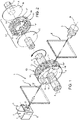
Figure 1 is a perspective view of a first embodiment of the speed detection system according to the invention; -
Figure 2 is an exploded perspective view of an element making part of the system offigure 1 ; -
Figure 3 is a perspective view of a second embodiment of the speed detection system according to the invention; -
Figure 4 is an exploded perspective view of an element making part of the system offigure 3 ; and -
Figure 5 is a perspective view of a third embodiment of the speed detection system according to the invention. - The
speed detection system 1 of the present invention essentially comprise a ionizingradiation source 2 configured to emit ionizing radiation such as γ-rays, a ionizingradiation detector 3 configured to detect ionizing radiation, theradiation source 2 is configured to interact with respect to the rotatingshaft 5 whose rotational speeds needs to be measured. The measured interaction by the detector is acquired by a control unit (not shown) configured to estimate the speed of theshaft 5 in function of the signal measured by thedetector 3. -
Source 2 may be selected according to radioactive material properties and requirements of safety of the vehicle. Non-limitative examples may be cobalt (Co-60) or iridium (Ir-192) or cesium (Cs-137). - In particular, the
shaft 5 is housed in a casing 6 (only schematic and partially shown) that isolates theshaft 5 from the environment. Theshaft 5 is rotatably support with respect tocasing 6 to allow its rotation about an axis A. In particular, thecasing 6 is made of a material that can be passed through by ionizing radiation emitted bysource 2. - According to the embodiment of
figures 1 and 2 , thesource 2 is carried outside thecasing 6, from another element of the vehicle (not shown) or by thecasing 6 itself. Thesource 2 compriseshousing 7 configured to delimit a space configured to house aradioactive element 8 configured to emit ionizing radiation γ. Thehousing 7 is realized in a material configured to avoid the passage of such ionizing radiation γ throughcasing 7 except for anopening 9 provided by ashutter 11. - Alternatively, the
housing 6 can be realized of non-radiologically-shielding material, depending on the intensity of the radiological emission of thesource 2. - The
shutter 11 is itself realized in a material configured to avoid passage of the ionizing radiation γ and configured to assume a first operative condition wherein it closes theopening 9, thereby avoiding the passage of ionizing radiation γ and a second operative condition wherein it allows the passage of ionizing radiation γ through opening 9. - The
casing 7 is disposed with respect to theshaft 5 so that theshutter 11 allows the projection of ionizing radiation γ along a direction B that is transversal with respect to longitudinal axis A of the shaft. Preferably, such direction B is perpendicular to axis A. - The
detector 3 is carried outside thecasing 6, from another elements of the vehicle (not shown) or by thecasing 6 itself. In particular, thedetector 3 is placed on an opposite side with respect tohousing 6 and collinear to direction B thereby being invested by the ionizing radiation γ in its entirety. Thedetector 3 may comprise any suitable ionizing radiation sensor and is electrically connected, by wire or electromagnetically, to an electronic control unit (not shown). - The
system 1 further comprises ashielding unit 13 fixedly carried byshaft 5 and interposed along direction B thereby being traversed by ionizing radiation γ emitted bysource 5. - The
shielding unit 13 has material properties that circumferential varies about axis A thereby varying the amount of ionizing radiation γ that may pass through this latter, in particular selectively allowing the passage of the ionizing radiation γ. - In particular, the
shielding unit 13 comprises ashielding element 14 that partially surroundsshaft 5 about axis A and that is realized in an ionizing radiation γ shielding material such as lead. In particular theshielding element 14 may be realized in at least a portion. - In the described embodiment, the
shielding unit 13 comprises a pair of shielding elements 14', 14'' that extends on opposite sides with respect toshaft 5 for a circumferential angular extension about axis B that is lower with respect to 180°. Such pair ofshielding elements 14', 14" are axially compressed betweenplates 15 that are rigidly carried byshaft 5. - According to the above construction, the
shielding unit 13 defines a pair ofopenings 16 that may be empty or, as in the disclosed embodiment that may housetransparent elements 17 with respect to ionizing radiation. Clearly, if the number ofshielding elements 14 is different, the number oftransparent elements 17 varies consequently. - The operation of the
speed detection system 1 of the above-described embodiment is the following. - When it is needed to estimate the speed of
shaft 5, a control unit may controlshutter 11 tofree opening 9 thereby allowing the ionizing radiation γ to be directed againstshaft 5 andshielding unit 13. Indeed the ionizing radiation γ passes throughcasing 6, attenuating itself and hits theshielding unit 13. According to speed rotation, the ionizing radiation γ will be obscured byshielding elements 14', 14" or pass, attenuated, throughshaft 5 viaopenings 16. Then, the ionizing radiation γ will pass out fromcasing 6, further attenuated, and will be measured bydetector 3. - The
detector 3 receives therefore impulses with a frequency dependent to rotation ofshaft 5 of ionizing radiation γ and this information may be read by control unit that, as known, may determine rotational speed ofshaft 5 or that may elaborate such impulse signal to obtain different mathematical paths, e.g. via Fourier transformation. At the end of the measurement, theshutter 9 is closed, to ensure radiological safety to the operators. - When the vehicle no more needs to measure the speed of
such shaft 5,source 2 may be removed to the vehicle and stored in a safe space. - The embodiment of
figures 3 and 4 is differentiated by the fact that theradiation source 2 is carried rotatably fixed toshaft 5. - According to the above, the
detector 3 is placed outsidehousing 6, preferably along a direction B as in the embodiment offigures 1 and 2 , to detect impulses of ionizing radiation provided bysource 2 when rotating about axis A and collinear with direction B. - Advantageously, the
housing 6 may be realized in a ionizing radiation shielding material except by a wall ofhousing 6 interposed betweendetector 3 andshaft 5 wherein aportion 6a thereof may be realized in a material that has lower ionizing radiation shielding material thereby allowing the passage of radiation coming fromsource 2 when collinear to direction B. - The
source 2 may be advantageously carried by ahousing assembly 20 that further comprises ashielding element 14 that at least partially surroundsshaft 5 about axis A and that is realized in an ionizing radiation shielding material such as lead. - In the described embodiment, the
housing unit 13 comprises asingle shielding element 14 that is "C-shaped", i.e. that circumferentially surroundsshaft 5 about axis B except for a portion occupied bysource 2. Accordingly,source 2 is circumferentially fixed between theshielding elements 14 that therefore has a circumferential extension that is greater than 270° about axis A. Theshielding element 14 andsource 2 are axially compressed betweenplates 15 that are rigidly carried byshaft 5. - The fixing of
source 2 may be obtained by glue, low temperature melting or non-radiologically shielding material also in function of dimensions of the shaft and the estimated work speed, i.e. taking into account the stresses due to centrifugal forces and the environment it shall work in (e.g.: temperature, acidity, etc.). - The operation of the
speed detection system 1 of the above-described embodiment is the following. - The ionizing radiation γ is continuously generated by
source 2 that rotates about axis A. The ionizing radiation γ may pass throughcasing 6 via portion a thereby being kept bydetector 3. - The
detector 3 receives therefore impulses with a frequency dependent to rotation ofshaft 5 of ionizing radiation γ and this information may be red by control unit that, as known, may determine rotational speed ofshaft 5 or that may elaborate such impulse signal to obtain different mathematical paths, e.g. via Fourier transformation. - The embodiment of
figure 5 differentiates with respect to the embodiment offigures 3 and 4 by the presence of anauxiliary shaft 21 outsidehousing 6 and interposed along direction B of ionizing radiation source betweenhousing 6 anddetector 3. - In particular,
shaft 21 is a shaft of the vehicle which speed is easily detectable, being outsidehousing 6 and extends about an axis C that is preferably parallel to axis A. Advantageously, the speed ofshaft 21 is controllable by the control unit deputed to detection of signals kept bydetector 3. - The
shaft 21 is configured to sample the radiation flux before reachingdetector 3, as outlined below. - The operation of the
speed detection system 1 of the above-described embodiment is the following. - The ionizing radiation γ is continuously generated by
source 2 that rotates about axis A. The ionizing radiation γ may pass throughcasing 6 via portion a thereby impacting onauxiliary shaft 21. - According to speed rotation of
shaft 21, the ionizing radiation γ will be obscured by shieldingelements 14', 14" or pass, attenuated, throughshaft 21 viaopenings 16. Then, the ionizing radiation γ will be kept bydetector 3. - The
detector 3 receives therefore impulses with a frequency dependent to the combination of the rotation of theshaft 5, whose speed is unknown, and the rotation ofauxiliary shaft 21 whose speed is known and can be controlled. - The control unit may vary the speed of
auxiliary shaft 21 to minimize the radiation value that may be detected bydetector 3. In such case, it is assumed that the position of the two shaft is the same. - It is therefore clear from the above that the present invention furthermore relates to a method for estimating the speed of a shaft comprising the steps of:
- Providing a flux of a ionizing radiation γ from a radiation source;
- Making interact the ionizing radiation γ flux with a rotating shaft whose speed needs to be measured;
- Measuring the flux of ionizing radiation γ after the interaction with the rotating shaft; and
- Estimating the speed of the shaft in function the aforementioned measure.
- In particular, the interaction may be achieved by providing a flux of ionizing radiation γ against a rotating shaft or by making rotate the source that provides the flux of ionizing radiation γ at the same speed of the shaft.
- The method may further comprise the step of sampling the ionizing radiation γ after the interaction with the rotating shaft via an auxiliary shaft that rotates at a variable speed.
- In such case, the estimation of speed comprises a minimization step wherein the speed of the auxiliary shaft is varied until the measured ionizing radiation γ is about zero/at a minimum value.
- In view of the foregoing, the advantages of the system and method for speed detection of a shaft according to the invention are apparent.
- Thanks to the proposed system, it is possible to measure in a safe and precise manner the speed of shafts encased in housings of work vehicles.
- In particular, the proposed system allows to measure in a precise manner the speed also in case of vibrations or dirty elements.
- Moreover, it is possible to measure a very wide speed range. In particular, it is furthermore possible to measure variable speeds shafts provided by selecting a suitable detector having a sensibility at least ten times greater with respect to speed variation.
- When source is not internal to casing enclosing the shaft, it can be removed, thereby reducing radioactive risks.
- Thanks to the sampling of the auxiliary shaft, it is possible to measure very low value speed ranges. Accordingly, the system is versatile to detect a wide speed range.
- It is clear that modifications can be made to the described system and method for speed detection of a shaft that do not extend beyond the scope of protection defined by the claims.
- As said, the source may be of different typology and placed in different location with respect to the shaft or on the shaft itself. Similar consideration is valid for detector.
- Moreover, in function of the speed rotation range, the radiation flux may be sampled by more than a single auxiliary shaft.
- Furthermore, it is clear that the shielding assembly may be realized in different way and defining one or more openings through which the ionizing radiation may pass without shielding.
- Clearly, the proposed embodiments may be combined together, e.g. to provide a system having an external source and provided with an auxiliary shaft.
Claims (16)
- Speed detection system (1) for detecting the speed of a rotating shaft (5), said system (1) comprising a ionizing radiation source (2) configured to emit ionizing radiation (γ), a ionizing radiation detector (3) configured to detect ionizing radiation (γ), wherein the ionizing radiation (γ) is configured to interact with respect to the rotating shaft (5), said interaction being detected by said ionizing radiation detector (3), said system (1) further comprising a control unit configured to be electrically connected to said ionizing radiation detector (3), said control unit estimating the speed of said shaft (5) on the base of the signal detected by said ionizing radiation detector (3).
- Speed detection system according to claim 1, wherein said shaft (5) is enclosed in a closed housing (6).
- Speed detection system according to claim 1 or 2, wherein said ionizing radiation (γ) is a gamma rays radiation.
- Speed detection system according to any of the preceding claims, wherein said source (2) is fixedly carried by said vehicle and directed to provide a flux of ionizing radiation (γ) on a direction incident with respect to a longitudinal axis (A) of said rotating shaft (5).
- Speed detection system according to claim 3, wherein said source (2) is contained in a housing (7) fixedly carried by said vehicle and provided with an opening (9) directed towards said rotating shaft (5), said housing (7) being provided with shutter means (11) configured to selectively open or close said opening (9), said housing (7) being realized in ionizing radiation shielding material.
- Speed detection system according to claims 4 or 5, comprising a shielding assembly (13) configured to be fixedly carried by said shaft (5) in a position to be traversed by said ionizing radiation (γ), said shielding assembly (13) being realized in a material having material properties that circumferential varies about longitudinal axis of said shaft, thereby selectively shield the ionizing radiation (γ) in function of the rotation of said shaft (5).
- Speed detection system according to any of claims 1 to 3, wherein said source (2) is carried by said rotating shaft (5).
- Speed detection system according to claim 7, wherein aid source (2) is carried radially external to said shaft (5), said shaft (5) being provided a shielding material element (14) that circumferentially surrounds shaft source (2) thereby allowing to provide a flux of ionizing radiation (γ) only in a radial direction.
- Speed detection system according to any of the preceding claims, further comprising an auxiliary shaft (21) interposed between the shaft (5) and said detector (3), said auxiliary shaft (21) rotating at a known speed thereby sampling the flux of ionizing radiation after (γ) said interaction with said shaft (5).
- Speed detection system according to claim 9, wherein said auxiliary shaft (21) comprising a shielding assembly (13) configured to be fixedly carried by said auxiliary shaft (21) in a position to be traversed by said ionizing radiation (γ), said shielding assembly (13) being realized in a material having material properties that circumferential varies about longitudinal axis of said shaft, thereby selectively shield the ionizing radiation (γ) in function of the rotation of said shaft (5) .
- Speed detection system according to any of claims 2 to 10, wherein said casing (6) defines a portion (6a) that has different material properties with respect to the remaining portion of the casing (6) thereby allowing the passage of said flux of ionizing radiation (γ).
- Speed detection system according to claims 6 and 10, wherein said shielding assembly (13) comprises a shielding element (14) that partially surrounds the shaft (5, 21) about its longitudinal axis (A, C) and that is realized in a ionizing radiation shielding material.
- Method for estimating the speed of a shaft comprising the steps of:• Providing a flux of a ionizing radiation γ from a radiation source;• Making interact the ionizing radiation γ flux with a rotating shaft whose speed needs to be measured;• Measuring the flux of ionizing radiation γ after the interaction with the rotating shaft; and• Estimating the speed of the shaft in function of the aforementioned measure.
- Method according to claim 13, wherein said interaction may be achieved by providing a flux of ionizing radiation γ against a rotating shaft or by making rotate the source that provides the flux of ionizing radiation γ at the same speed of the shaft.
- Method according to claim 13 or 14, further comprising a step of sampling the ionizing radiation γ after the interaction with the rotating shaft via an auxiliary shaft that rotates at a variable speed.
- Method according to claim 15, wherein the estimation of speed comprises a minimization step wherein the speed of the auxiliary shaft is varied until the measured ionizing radiation γ is about zero/at a minimum value.
Applications Claiming Priority (1)
| Application Number | Priority Date | Filing Date | Title |
|---|---|---|---|
| IT102021000008510A IT202100008510A1 (en) | 2021-04-06 | 2021-04-06 | SYSTEM AND METHOD FOR DETECTING THE ROTATIONAL SPEED OF A SHAFT FOR A WORK VEHICLE |
Publications (2)
| Publication Number | Publication Date |
|---|---|
| EP4075148A1 true EP4075148A1 (en) | 2022-10-19 |
| EP4075148B1 EP4075148B1 (en) | 2024-02-07 |
Family
ID=76375567
Family Applications (1)
| Application Number | Title | Priority Date | Filing Date |
|---|---|---|---|
| EP22166732.2A Active EP4075148B1 (en) | 2021-04-06 | 2022-04-05 | System and method for detecting rotational speed of shaft for a work vehicle |
Country Status (2)
| Country | Link |
|---|---|
| EP (1) | EP4075148B1 (en) |
| IT (1) | IT202100008510A1 (en) |
Citations (5)
| Publication number | Priority date | Publication date | Assignee | Title |
|---|---|---|---|---|
| US2692951A (en) * | 1952-02-26 | 1954-10-26 | Sun Oil Co | Apparatus for measuring shaft rotation |
| US3012144A (en) * | 1957-06-12 | 1961-12-05 | Gen Motors Corp | Tachometer |
| US3358279A (en) * | 1963-09-19 | 1967-12-12 | Industrial Nucleonics Corp | Position indicating apparatus |
| DE4014431C1 (en) * | 1990-05-05 | 1991-07-04 | Heraeus Sepatech Gmbh, 3360 Osterode, De | |
| WO1996011407A1 (en) * | 1994-10-05 | 1996-04-18 | Motorola Semiconducteurs S.A. | Rotation sensor |
-
2021
- 2021-04-06 IT IT102021000008510A patent/IT202100008510A1/en unknown
-
2022
- 2022-04-05 EP EP22166732.2A patent/EP4075148B1/en active Active
Patent Citations (5)
| Publication number | Priority date | Publication date | Assignee | Title |
|---|---|---|---|---|
| US2692951A (en) * | 1952-02-26 | 1954-10-26 | Sun Oil Co | Apparatus for measuring shaft rotation |
| US3012144A (en) * | 1957-06-12 | 1961-12-05 | Gen Motors Corp | Tachometer |
| US3358279A (en) * | 1963-09-19 | 1967-12-12 | Industrial Nucleonics Corp | Position indicating apparatus |
| DE4014431C1 (en) * | 1990-05-05 | 1991-07-04 | Heraeus Sepatech Gmbh, 3360 Osterode, De | |
| WO1996011407A1 (en) * | 1994-10-05 | 1996-04-18 | Motorola Semiconducteurs S.A. | Rotation sensor |
Also Published As
| Publication number | Publication date |
|---|---|
| EP4075148B1 (en) | 2024-02-07 |
| IT202100008510A1 (en) | 2022-10-06 |
Similar Documents
| Publication | Publication Date | Title |
|---|---|---|
| US4777367A (en) | Method and apparatus for measuring the distribution of radioactivity | |
| US8600690B2 (en) | System and method for the transmission of signals | |
| US4053767A (en) | Method and apparatus for stabilizing signals in radioactive well logging tools | |
| US2692951A (en) | Apparatus for measuring shaft rotation | |
| NL9200053A (en) | METHOD FOR ANALYZING FORMATION DATA FROM A MEASUREMENT DURING DRILLING LOGIN INSTRUMENT FOR ASSESSING SOIL FORMATIONS. | |
| JPH06508926A (en) | Selective simultaneous detection process and detection device for neutrons and X or γ photons | |
| US5442180A (en) | Apparatus for the field determination of concentration of radioactive constituents in a medium | |
| US20070278423A1 (en) | Quantitative transmission/emission detector system and methods of detecting concealed radiation sources | |
| EP4075148B1 (en) | System and method for detecting rotational speed of shaft for a work vehicle | |
| US3030512A (en) | Monochromator system | |
| US5635710A (en) | Subsurface penetrometer radiaton sensor probe and system | |
| US5021652A (en) | Directional gamma ray spectrometer | |
| JPH1048398A (en) | X-ray diffractometer | |
| US8878140B2 (en) | Methods for radiation detection and characterization using a multiple detector probe | |
| US3932758A (en) | Method and apparatus for determining the dose value of neutrons | |
| JPH08220029A (en) | Nondestructive inspection device and inspection method for radioactive pollutants | |
| CA1081865A (en) | Method and apparatus for calibrating radioactivity well logging tools | |
| KR20100069255A (en) | A radiation detector capable of detecting the direction of radiation source | |
| US3080479A (en) | Gamma ray caliper | |
| US3167652A (en) | Miss distance and vector measurement system | |
| JP2018205070A (en) | Radiation measurement equipment | |
| US4136281A (en) | Energy fluence meter for x-rays | |
| US7795599B2 (en) | Radioactivity monitoring apparatus and method | |
| US4593195A (en) | Method and device for obtaining information relative to organic materials or minerals likely to be contained in geological formations | |
| JPH01152390A (en) | Fast neutron detector |
Legal Events
| Date | Code | Title | Description |
|---|---|---|---|
| PUAI | Public reference made under article 153(3) epc to a published international application that has entered the european phase |
Free format text: ORIGINAL CODE: 0009012 |
|
| STAA | Information on the status of an ep patent application or granted ep patent |
Free format text: STATUS: THE APPLICATION HAS BEEN PUBLISHED |
|
| AK | Designated contracting states |
Kind code of ref document: A1 Designated state(s): AL AT BE BG CH CY CZ DE DK EE ES FI FR GB GR HR HU IE IS IT LI LT LU LV MC MK MT NL NO PL PT RO RS SE SI SK SM TR |
|
| STAA | Information on the status of an ep patent application or granted ep patent |
Free format text: STATUS: REQUEST FOR EXAMINATION WAS MADE |
|
| 17P | Request for examination filed |
Effective date: 20230419 |
|
| RBV | Designated contracting states (corrected) |
Designated state(s): AL AT BE BG CH CY CZ DE DK EE ES FI FR GB GR HR HU IE IS IT LI LT LU LV MC MK MT NL NO PL PT RO RS SE SI SK SM TR |
|
| RAP3 | Party data changed (applicant data changed or rights of an application transferred) |
Owner name: CNH INDUSTRIAL ITALIA S.P.A. |
|
| GRAP | Despatch of communication of intention to grant a patent |
Free format text: ORIGINAL CODE: EPIDOSNIGR1 |
|
| STAA | Information on the status of an ep patent application or granted ep patent |
Free format text: STATUS: GRANT OF PATENT IS INTENDED |
|
| INTG | Intention to grant announced |
Effective date: 20230831 |
|
| GRAS | Grant fee paid |
Free format text: ORIGINAL CODE: EPIDOSNIGR3 |
|
| GRAA | (expected) grant |
Free format text: ORIGINAL CODE: 0009210 |
|
| STAA | Information on the status of an ep patent application or granted ep patent |
Free format text: STATUS: THE PATENT HAS BEEN GRANTED |
|
| AK | Designated contracting states |
Kind code of ref document: B1 Designated state(s): AL AT BE BG CH CY CZ DE DK EE ES FI FR GB GR HR HU IE IS IT LI LT LU LV MC MK MT NL NO PL PT RO RS SE SI SK SM TR |
|
| REG | Reference to a national code |
Ref country code: GB Ref legal event code: FG4D |
|
| REG | Reference to a national code |
Ref country code: CH Ref legal event code: EP |
|
| REG | Reference to a national code |
Ref country code: IE Ref legal event code: FG4D |
|
| REG | Reference to a national code |
Ref country code: DE Ref legal event code: R096 Ref document number: 602022001836 Country of ref document: DE |
|
| REG | Reference to a national code |
Ref country code: LT Ref legal event code: MG9D |
|
| REG | Reference to a national code |
Ref country code: NL Ref legal event code: MP Effective date: 20240207 |
|
| PG25 | Lapsed in a contracting state [announced via postgrant information from national office to epo] |
Ref country code: IS Free format text: LAPSE BECAUSE OF FAILURE TO SUBMIT A TRANSLATION OF THE DESCRIPTION OR TO PAY THE FEE WITHIN THE PRESCRIBED TIME-LIMIT Effective date: 20240607 |
|
| PG25 | Lapsed in a contracting state [announced via postgrant information from national office to epo] |
Ref country code: LT Free format text: LAPSE BECAUSE OF FAILURE TO SUBMIT A TRANSLATION OF THE DESCRIPTION OR TO PAY THE FEE WITHIN THE PRESCRIBED TIME-LIMIT Effective date: 20240207 |
|
| PG25 | Lapsed in a contracting state [announced via postgrant information from national office to epo] |
Ref country code: GR Free format text: LAPSE BECAUSE OF FAILURE TO SUBMIT A TRANSLATION OF THE DESCRIPTION OR TO PAY THE FEE WITHIN THE PRESCRIBED TIME-LIMIT Effective date: 20240508 |
|
| REG | Reference to a national code |
Ref country code: AT Ref legal event code: MK05 Ref document number: 1655695 Country of ref document: AT Kind code of ref document: T Effective date: 20240207 |
|
| PG25 | Lapsed in a contracting state [announced via postgrant information from national office to epo] |
Ref country code: HR Free format text: LAPSE BECAUSE OF FAILURE TO SUBMIT A TRANSLATION OF THE DESCRIPTION OR TO PAY THE FEE WITHIN THE PRESCRIBED TIME-LIMIT Effective date: 20240207 Ref country code: RS Free format text: LAPSE BECAUSE OF FAILURE TO SUBMIT A TRANSLATION OF THE DESCRIPTION OR TO PAY THE FEE WITHIN THE PRESCRIBED TIME-LIMIT Effective date: 20240507 Ref country code: NL Free format text: LAPSE BECAUSE OF FAILURE TO SUBMIT A TRANSLATION OF THE DESCRIPTION OR TO PAY THE FEE WITHIN THE PRESCRIBED TIME-LIMIT Effective date: 20240207 |
|
| PG25 | Lapsed in a contracting state [announced via postgrant information from national office to epo] |
Ref country code: ES Free format text: LAPSE BECAUSE OF FAILURE TO SUBMIT A TRANSLATION OF THE DESCRIPTION OR TO PAY THE FEE WITHIN THE PRESCRIBED TIME-LIMIT Effective date: 20240207 |
|
| PG25 | Lapsed in a contracting state [announced via postgrant information from national office to epo] |
Ref country code: AT Free format text: LAPSE BECAUSE OF FAILURE TO SUBMIT A TRANSLATION OF THE DESCRIPTION OR TO PAY THE FEE WITHIN THE PRESCRIBED TIME-LIMIT Effective date: 20240207 |
|
| PG25 | Lapsed in a contracting state [announced via postgrant information from national office to epo] |
Ref country code: RS Free format text: LAPSE BECAUSE OF FAILURE TO SUBMIT A TRANSLATION OF THE DESCRIPTION OR TO PAY THE FEE WITHIN THE PRESCRIBED TIME-LIMIT Effective date: 20240507 Ref country code: NO Free format text: LAPSE BECAUSE OF FAILURE TO SUBMIT A TRANSLATION OF THE DESCRIPTION OR TO PAY THE FEE WITHIN THE PRESCRIBED TIME-LIMIT Effective date: 20240507 Ref country code: NL Free format text: LAPSE BECAUSE OF FAILURE TO SUBMIT A TRANSLATION OF THE DESCRIPTION OR TO PAY THE FEE WITHIN THE PRESCRIBED TIME-LIMIT Effective date: 20240207 Ref country code: LT Free format text: LAPSE BECAUSE OF FAILURE TO SUBMIT A TRANSLATION OF THE DESCRIPTION OR TO PAY THE FEE WITHIN THE PRESCRIBED TIME-LIMIT Effective date: 20240207 Ref country code: IS Free format text: LAPSE BECAUSE OF FAILURE TO SUBMIT A TRANSLATION OF THE DESCRIPTION OR TO PAY THE FEE WITHIN THE PRESCRIBED TIME-LIMIT Effective date: 20240607 Ref country code: HR Free format text: LAPSE BECAUSE OF FAILURE TO SUBMIT A TRANSLATION OF THE DESCRIPTION OR TO PAY THE FEE WITHIN THE PRESCRIBED TIME-LIMIT Effective date: 20240207 Ref country code: GR Free format text: LAPSE BECAUSE OF FAILURE TO SUBMIT A TRANSLATION OF THE DESCRIPTION OR TO PAY THE FEE WITHIN THE PRESCRIBED TIME-LIMIT Effective date: 20240508 Ref country code: FI Free format text: LAPSE BECAUSE OF FAILURE TO SUBMIT A TRANSLATION OF THE DESCRIPTION OR TO PAY THE FEE WITHIN THE PRESCRIBED TIME-LIMIT Effective date: 20240207 Ref country code: ES Free format text: LAPSE BECAUSE OF FAILURE TO SUBMIT A TRANSLATION OF THE DESCRIPTION OR TO PAY THE FEE WITHIN THE PRESCRIBED TIME-LIMIT Effective date: 20240207 Ref country code: BG Free format text: LAPSE BECAUSE OF FAILURE TO SUBMIT A TRANSLATION OF THE DESCRIPTION OR TO PAY THE FEE WITHIN THE PRESCRIBED TIME-LIMIT Effective date: 20240207 Ref country code: AT Free format text: LAPSE BECAUSE OF FAILURE TO SUBMIT A TRANSLATION OF THE DESCRIPTION OR TO PAY THE FEE WITHIN THE PRESCRIBED TIME-LIMIT Effective date: 20240207 |
|
| PG25 | Lapsed in a contracting state [announced via postgrant information from national office to epo] |
Ref country code: PL Free format text: LAPSE BECAUSE OF FAILURE TO SUBMIT A TRANSLATION OF THE DESCRIPTION OR TO PAY THE FEE WITHIN THE PRESCRIBED TIME-LIMIT Effective date: 20240207 Ref country code: PT Free format text: LAPSE BECAUSE OF FAILURE TO SUBMIT A TRANSLATION OF THE DESCRIPTION OR TO PAY THE FEE WITHIN THE PRESCRIBED TIME-LIMIT Effective date: 20240607 |
|
| PG25 | Lapsed in a contracting state [announced via postgrant information from national office to epo] |
Ref country code: SE Free format text: LAPSE BECAUSE OF FAILURE TO SUBMIT A TRANSLATION OF THE DESCRIPTION OR TO PAY THE FEE WITHIN THE PRESCRIBED TIME-LIMIT Effective date: 20240207 Ref country code: PT Free format text: LAPSE BECAUSE OF FAILURE TO SUBMIT A TRANSLATION OF THE DESCRIPTION OR TO PAY THE FEE WITHIN THE PRESCRIBED TIME-LIMIT Effective date: 20240607 Ref country code: PL Free format text: LAPSE BECAUSE OF FAILURE TO SUBMIT A TRANSLATION OF THE DESCRIPTION OR TO PAY THE FEE WITHIN THE PRESCRIBED TIME-LIMIT Effective date: 20240207 Ref country code: LV Free format text: LAPSE BECAUSE OF FAILURE TO SUBMIT A TRANSLATION OF THE DESCRIPTION OR TO PAY THE FEE WITHIN THE PRESCRIBED TIME-LIMIT Effective date: 20240207 |
|
| PG25 | Lapsed in a contracting state [announced via postgrant information from national office to epo] |
Ref country code: DK Free format text: LAPSE BECAUSE OF FAILURE TO SUBMIT A TRANSLATION OF THE DESCRIPTION OR TO PAY THE FEE WITHIN THE PRESCRIBED TIME-LIMIT Effective date: 20240207 |
|
| PG25 | Lapsed in a contracting state [announced via postgrant information from national office to epo] |
Ref country code: SM Free format text: LAPSE BECAUSE OF FAILURE TO SUBMIT A TRANSLATION OF THE DESCRIPTION OR TO PAY THE FEE WITHIN THE PRESCRIBED TIME-LIMIT Effective date: 20240207 |
|
| PG25 | Lapsed in a contracting state [announced via postgrant information from national office to epo] |
Ref country code: CZ Free format text: LAPSE BECAUSE OF FAILURE TO SUBMIT A TRANSLATION OF THE DESCRIPTION OR TO PAY THE FEE WITHIN THE PRESCRIBED TIME-LIMIT Effective date: 20240207 Ref country code: EE Free format text: LAPSE BECAUSE OF FAILURE TO SUBMIT A TRANSLATION OF THE DESCRIPTION OR TO PAY THE FEE WITHIN THE PRESCRIBED TIME-LIMIT Effective date: 20240207 |
|
| PG25 | Lapsed in a contracting state [announced via postgrant information from national office to epo] |
Ref country code: SK Free format text: LAPSE BECAUSE OF FAILURE TO SUBMIT A TRANSLATION OF THE DESCRIPTION OR TO PAY THE FEE WITHIN THE PRESCRIBED TIME-LIMIT Effective date: 20240207 |
|
| PG25 | Lapsed in a contracting state [announced via postgrant information from national office to epo] |
Ref country code: SM Free format text: LAPSE BECAUSE OF FAILURE TO SUBMIT A TRANSLATION OF THE DESCRIPTION OR TO PAY THE FEE WITHIN THE PRESCRIBED TIME-LIMIT Effective date: 20240207 Ref country code: SK Free format text: LAPSE BECAUSE OF FAILURE TO SUBMIT A TRANSLATION OF THE DESCRIPTION OR TO PAY THE FEE WITHIN THE PRESCRIBED TIME-LIMIT Effective date: 20240207 Ref country code: RO Free format text: LAPSE BECAUSE OF FAILURE TO SUBMIT A TRANSLATION OF THE DESCRIPTION OR TO PAY THE FEE WITHIN THE PRESCRIBED TIME-LIMIT Effective date: 20240207 Ref country code: EE Free format text: LAPSE BECAUSE OF FAILURE TO SUBMIT A TRANSLATION OF THE DESCRIPTION OR TO PAY THE FEE WITHIN THE PRESCRIBED TIME-LIMIT Effective date: 20240207 Ref country code: DK Free format text: LAPSE BECAUSE OF FAILURE TO SUBMIT A TRANSLATION OF THE DESCRIPTION OR TO PAY THE FEE WITHIN THE PRESCRIBED TIME-LIMIT Effective date: 20240207 Ref country code: CZ Free format text: LAPSE BECAUSE OF FAILURE TO SUBMIT A TRANSLATION OF THE DESCRIPTION OR TO PAY THE FEE WITHIN THE PRESCRIBED TIME-LIMIT Effective date: 20240207 |
|
| REG | Reference to a national code |
Ref country code: DE Ref legal event code: R097 Ref document number: 602022001836 Country of ref document: DE |
|
| PG25 | Lapsed in a contracting state [announced via postgrant information from national office to epo] |
Ref country code: MC Free format text: LAPSE BECAUSE OF FAILURE TO SUBMIT A TRANSLATION OF THE DESCRIPTION OR TO PAY THE FEE WITHIN THE PRESCRIBED TIME-LIMIT Effective date: 20240207 |
|
| PG25 | Lapsed in a contracting state [announced via postgrant information from national office to epo] |
Ref country code: MC Free format text: LAPSE BECAUSE OF FAILURE TO SUBMIT A TRANSLATION OF THE DESCRIPTION OR TO PAY THE FEE WITHIN THE PRESCRIBED TIME-LIMIT Effective date: 20240207 |
|
| PLBE | No opposition filed within time limit |
Free format text: ORIGINAL CODE: 0009261 |
|
| STAA | Information on the status of an ep patent application or granted ep patent |
Free format text: STATUS: NO OPPOSITION FILED WITHIN TIME LIMIT |
|
| PG25 | Lapsed in a contracting state [announced via postgrant information from national office to epo] |
Ref country code: LU Free format text: LAPSE BECAUSE OF NON-PAYMENT OF DUE FEES Effective date: 20240405 |
|
| REG | Reference to a national code |
Ref country code: BE Ref legal event code: MM Effective date: 20240430 |
|
| PG25 | Lapsed in a contracting state [announced via postgrant information from national office to epo] |
Ref country code: LU Free format text: LAPSE BECAUSE OF NON-PAYMENT OF DUE FEES Effective date: 20240405 |
|
| 26N | No opposition filed |
Effective date: 20241108 |
|
| PG25 | Lapsed in a contracting state [announced via postgrant information from national office to epo] |
Ref country code: BE Free format text: LAPSE BECAUSE OF NON-PAYMENT OF DUE FEES Effective date: 20240430 |
|
| PG25 | Lapsed in a contracting state [announced via postgrant information from national office to epo] |
Ref country code: BE Free format text: LAPSE BECAUSE OF NON-PAYMENT OF DUE FEES Effective date: 20240430 |
|
| PG25 | Lapsed in a contracting state [announced via postgrant information from national office to epo] |
Ref country code: IE Free format text: LAPSE BECAUSE OF NON-PAYMENT OF DUE FEES Effective date: 20240405 |
|
| PG25 | Lapsed in a contracting state [announced via postgrant information from national office to epo] |
Ref country code: SI Free format text: LAPSE BECAUSE OF FAILURE TO SUBMIT A TRANSLATION OF THE DESCRIPTION OR TO PAY THE FEE WITHIN THE PRESCRIBED TIME-LIMIT Effective date: 20240207 |
|
| PG25 | Lapsed in a contracting state [announced via postgrant information from national office to epo] |
Ref country code: CY Free format text: LAPSE BECAUSE OF FAILURE TO SUBMIT A TRANSLATION OF THE DESCRIPTION OR TO PAY THE FEE WITHIN THE PRESCRIBED TIME-LIMIT; INVALID AB INITIO Effective date: 20220405 |
|
| REG | Reference to a national code |
Ref country code: CH Ref legal event code: H13 Free format text: ST27 STATUS EVENT CODE: U-0-0-H10-H13 (AS PROVIDED BY THE NATIONAL OFFICE) Effective date: 20251125 |
|
| PG25 | Lapsed in a contracting state [announced via postgrant information from national office to epo] |
Ref country code: TR Free format text: LAPSE BECAUSE OF FAILURE TO SUBMIT A TRANSLATION OF THE DESCRIPTION OR TO PAY THE FEE WITHIN THE PRESCRIBED TIME-LIMIT Effective date: 20240207 |
|
| PG25 | Lapsed in a contracting state [announced via postgrant information from national office to epo] |
Ref country code: CH Free format text: LAPSE BECAUSE OF NON-PAYMENT OF DUE FEES Effective date: 20250430 |
|
| PG25 | Lapsed in a contracting state [announced via postgrant information from national office to epo] |
Ref country code: CH Free format text: THE PATENT HAS BEEN ANNULLED BY A DECISION OF A NATIONAL AUTHORITY Effective date: 20250430 |
|
| PGFP | Annual fee paid to national office [announced via postgrant information from national office to epo] |
Ref country code: GB Payment date: 20260421 Year of fee payment: 5 |
|
| PGFP | Annual fee paid to national office [announced via postgrant information from national office to epo] |
Ref country code: IT Payment date: 20260422 Year of fee payment: 5 |
|
| PGFP | Annual fee paid to national office [announced via postgrant information from national office to epo] |
Ref country code: DE Payment date: 20260421 Year of fee payment: 5 |
|
| PGFP | Annual fee paid to national office [announced via postgrant information from national office to epo] |
Ref country code: FR Payment date: 20260423 Year of fee payment: 5 |