EP4075100A1 - Proximity sensor to sense rotating shaft position and velocity - Google Patents
Proximity sensor to sense rotating shaft position and velocity Download PDFInfo
- Publication number
- EP4075100A1 EP4075100A1 EP22166831.2A EP22166831A EP4075100A1 EP 4075100 A1 EP4075100 A1 EP 4075100A1 EP 22166831 A EP22166831 A EP 22166831A EP 4075100 A1 EP4075100 A1 EP 4075100A1
- Authority
- EP
- European Patent Office
- Prior art keywords
- shaft
- target element
- proximity sensor
- volume
- target
- Prior art date
- Legal status (The legal status is an assumption and is not a legal conclusion. Google has not performed a legal analysis and makes no representation as to the accuracy of the status listed.)
- Granted
Links
Images




Classifications
-
- G—PHYSICS
- G01—MEASURING; TESTING
- G01D—MEASURING NOT SPECIALLY ADAPTED FOR A SPECIFIC VARIABLE; ARRANGEMENTS FOR MEASURING TWO OR MORE VARIABLES NOT COVERED IN A SINGLE OTHER SUBCLASS; TARIFF METERING APPARATUS; MEASURING OR TESTING NOT OTHERWISE PROVIDED FOR
- G01D5/00—Mechanical means for transferring the output of a sensing member; Means for converting the output of a sensing member to another variable where the form or nature of the sensing member does not constrain the means for converting; Transducers not specially adapted for a specific variable
- G01D5/12—Mechanical means for transferring the output of a sensing member; Means for converting the output of a sensing member to another variable where the form or nature of the sensing member does not constrain the means for converting; Transducers not specially adapted for a specific variable using electric or magnetic means
- G01D5/14—Mechanical means for transferring the output of a sensing member; Means for converting the output of a sensing member to another variable where the form or nature of the sensing member does not constrain the means for converting; Transducers not specially adapted for a specific variable using electric or magnetic means influencing the magnitude of a current or voltage
- G01D5/20—Mechanical means for transferring the output of a sensing member; Means for converting the output of a sensing member to another variable where the form or nature of the sensing member does not constrain the means for converting; Transducers not specially adapted for a specific variable using electric or magnetic means influencing the magnitude of a current or voltage by varying inductance, e.g. by a movable armature
- G01D5/2006—Mechanical means for transferring the output of a sensing member; Means for converting the output of a sensing member to another variable where the form or nature of the sensing member does not constrain the means for converting; Transducers not specially adapted for a specific variable using electric or magnetic means influencing the magnitude of a current or voltage by varying inductance, e.g. by a movable armature by influencing the self-induction of one or more coils
-
- G—PHYSICS
- G01—MEASURING; TESTING
- G01D—MEASURING NOT SPECIALLY ADAPTED FOR A SPECIFIC VARIABLE; ARRANGEMENTS FOR MEASURING TWO OR MORE VARIABLES NOT COVERED IN A SINGLE OTHER SUBCLASS; TARIFF METERING APPARATUS; MEASURING OR TESTING NOT OTHERWISE PROVIDED FOR
- G01D5/00—Mechanical means for transferring the output of a sensing member; Means for converting the output of a sensing member to another variable where the form or nature of the sensing member does not constrain the means for converting; Transducers not specially adapted for a specific variable
- G01D5/12—Mechanical means for transferring the output of a sensing member; Means for converting the output of a sensing member to another variable where the form or nature of the sensing member does not constrain the means for converting; Transducers not specially adapted for a specific variable using electric or magnetic means
- G01D5/14—Mechanical means for transferring the output of a sensing member; Means for converting the output of a sensing member to another variable where the form or nature of the sensing member does not constrain the means for converting; Transducers not specially adapted for a specific variable using electric or magnetic means influencing the magnitude of a current or voltage
- G01D5/20—Mechanical means for transferring the output of a sensing member; Means for converting the output of a sensing member to another variable where the form or nature of the sensing member does not constrain the means for converting; Transducers not specially adapted for a specific variable using electric or magnetic means influencing the magnitude of a current or voltage by varying inductance, e.g. by a movable armature
- G01D5/2006—Mechanical means for transferring the output of a sensing member; Means for converting the output of a sensing member to another variable where the form or nature of the sensing member does not constrain the means for converting; Transducers not specially adapted for a specific variable using electric or magnetic means influencing the magnitude of a current or voltage by varying inductance, e.g. by a movable armature by influencing the self-induction of one or more coils
- G01D5/2013—Mechanical means for transferring the output of a sensing member; Means for converting the output of a sensing member to another variable where the form or nature of the sensing member does not constrain the means for converting; Transducers not specially adapted for a specific variable using electric or magnetic means influencing the magnitude of a current or voltage by varying inductance, e.g. by a movable armature by influencing the self-induction of one or more coils by a movable ferromagnetic element, e.g. a core
-
- G—PHYSICS
- G01—MEASURING; TESTING
- G01D—MEASURING NOT SPECIALLY ADAPTED FOR A SPECIFIC VARIABLE; ARRANGEMENTS FOR MEASURING TWO OR MORE VARIABLES NOT COVERED IN A SINGLE OTHER SUBCLASS; TARIFF METERING APPARATUS; MEASURING OR TESTING NOT OTHERWISE PROVIDED FOR
- G01D5/00—Mechanical means for transferring the output of a sensing member; Means for converting the output of a sensing member to another variable where the form or nature of the sensing member does not constrain the means for converting; Transducers not specially adapted for a specific variable
- G01D5/12—Mechanical means for transferring the output of a sensing member; Means for converting the output of a sensing member to another variable where the form or nature of the sensing member does not constrain the means for converting; Transducers not specially adapted for a specific variable using electric or magnetic means
- G01D5/14—Mechanical means for transferring the output of a sensing member; Means for converting the output of a sensing member to another variable where the form or nature of the sensing member does not constrain the means for converting; Transducers not specially adapted for a specific variable using electric or magnetic means influencing the magnitude of a current or voltage
- G01D5/20—Mechanical means for transferring the output of a sensing member; Means for converting the output of a sensing member to another variable where the form or nature of the sensing member does not constrain the means for converting; Transducers not specially adapted for a specific variable using electric or magnetic means influencing the magnitude of a current or voltage by varying inductance, e.g. by a movable armature
- G01D5/2006—Mechanical means for transferring the output of a sensing member; Means for converting the output of a sensing member to another variable where the form or nature of the sensing member does not constrain the means for converting; Transducers not specially adapted for a specific variable using electric or magnetic means influencing the magnitude of a current or voltage by varying inductance, e.g. by a movable armature by influencing the self-induction of one or more coils
- G01D5/202—Mechanical means for transferring the output of a sensing member; Means for converting the output of a sensing member to another variable where the form or nature of the sensing member does not constrain the means for converting; Transducers not specially adapted for a specific variable using electric or magnetic means influencing the magnitude of a current or voltage by varying inductance, e.g. by a movable armature by influencing the self-induction of one or more coils by movable a non-ferromagnetic conductive element
-
- G—PHYSICS
- G01—MEASURING; TESTING
- G01P—MEASURING LINEAR OR ANGULAR SPEED, ACCELERATION, DECELERATION, OR SHOCK; INDICATING PRESENCE, ABSENCE, OR DIRECTION, OF MOVEMENT
- G01P3/00—Measuring linear or angular speed; Measuring differences of linear or angular speeds
- G01P3/42—Devices characterised by the use of electric or magnetic means
- G01P3/44—Devices characterised by the use of electric or magnetic means for measuring angular speed
- G01P3/48—Devices characterised by the use of electric or magnetic means for measuring angular speed by measuring frequency of generated current or voltage
- G01P3/481—Devices characterised by the use of electric or magnetic means for measuring angular speed by measuring frequency of generated current or voltage of pulse signals
- G01P3/488—Devices characterised by the use of electric or magnetic means for measuring angular speed by measuring frequency of generated current or voltage of pulse signals delivered by variable reluctance detectors
-
- G—PHYSICS
- G01—MEASURING; TESTING
- G01P—MEASURING LINEAR OR ANGULAR SPEED, ACCELERATION, DECELERATION, OR SHOCK; INDICATING PRESENCE, ABSENCE, OR DIRECTION, OF MOVEMENT
- G01P3/00—Measuring linear or angular speed; Measuring differences of linear or angular speeds
- G01P3/42—Devices characterised by the use of electric or magnetic means
- G01P3/44—Devices characterised by the use of electric or magnetic means for measuring angular speed
- G01P3/49—Devices characterised by the use of electric or magnetic means for measuring angular speed using eddy currents
-
- F—MECHANICAL ENGINEERING; LIGHTING; HEATING; WEAPONS; BLASTING
- F16—ENGINEERING ELEMENTS AND UNITS; GENERAL MEASURES FOR PRODUCING AND MAINTAINING EFFECTIVE FUNCTIONING OF MACHINES OR INSTALLATIONS; THERMAL INSULATION IN GENERAL
- F16C—SHAFTS; FLEXIBLE SHAFTS; ELEMENTS OR CRANKSHAFT MECHANISMS; ROTARY BODIES OTHER THAN GEARING ELEMENTS; BEARINGS
- F16C2233/00—Monitoring condition, e.g. temperature, load, vibration
-
- F—MECHANICAL ENGINEERING; LIGHTING; HEATING; WEAPONS; BLASTING
- F16—ENGINEERING ELEMENTS AND UNITS; GENERAL MEASURES FOR PRODUCING AND MAINTAINING EFFECTIVE FUNCTIONING OF MACHINES OR INSTALLATIONS; THERMAL INSULATION IN GENERAL
- F16C—SHAFTS; FLEXIBLE SHAFTS; ELEMENTS OR CRANKSHAFT MECHANISMS; ROTARY BODIES OTHER THAN GEARING ELEMENTS; BEARINGS
- F16C3/00—Shafts; Axles; Cranks; Eccentrics
- F16C3/02—Shafts; Axles
-
- G—PHYSICS
- G01—MEASURING; TESTING
- G01D—MEASURING NOT SPECIALLY ADAPTED FOR A SPECIFIC VARIABLE; ARRANGEMENTS FOR MEASURING TWO OR MORE VARIABLES NOT COVERED IN A SINGLE OTHER SUBCLASS; TARIFF METERING APPARATUS; MEASURING OR TESTING NOT OTHERWISE PROVIDED FOR
- G01D2205/00—Indexing scheme relating to details of means for transferring or converting the output of a sensing member
- G01D2205/70—Position sensors comprising a moving target with particular shapes, e.g. of soft magnetic targets
- G01D2205/77—Specific profiles
- G01D2205/773—Spiral profiles
Definitions
- the present invention generally relates to electromechanical systems, and more particularly, to a system to monitor a position, and velocity of a rotating shaft.
- Aircrafts commonly employ rotatable shafts to adjust the position of one or more components on the vehicle.
- Aircrafts for example, include flaps, slats, landing gears, etc. that are adjusted in response to rotating a shaft in a clockwise and counterclockwise direction.
- velocity i.e., speed and direction
- position of the shaft in order to determine the current adjusted position of the moveable component, i.e., whether a given flap is open or closed.
- the rotational position of the shaft provides a corresponding relationship to the adjusted position of the moveable component (e.g., flat, slat, landing gear, etc.)
- some vehicles including aircraft employ dualfunction dynamoelectric machine that can be utilized as both a motor and as a generator.
- Embodiments of the present invention are directed to a shaft monitoring system.
- the shaft monitoring system includes a rotatable shaft having a target element coupled thereto that rotates along with the shaft.
- a proximity sensor is located adjacent the target element.
- the proximity sensor measures an inductance of the target element based on one or both of a volume of the target element and a distance between the target element and the proximity sensor, and generates a proximity sensor output signal based on the measured inductance.
- a signal processing system determines at least one of a position of the shaft, a rotational speed of the shaft, and a rotational direction of the shaft based on the proximity sensor output signal.
- Embodiments of the present invention are directed to a method of monitoring a rotatable shaft.
- the method comprises positioning a target element coupled to a rotatable shaft a distance away from a proximity sensor and measuring, via the proximity sensor, an inductance based on one or both of a volume of the target element and a distance between the target element and the proximity sensor.
- the method further comprises generating a proximity sensor output signal based on the measured inductance.
- the method further comprises determining, via a signal processing system in signal communication with the proximity sensor, at least one of a position of the shaft, a rotational speed of the shaft, and a rotational direction of the shaft based on the proximity sensor output signal.
- a wide-variety of devices have traditionally been used to measure the rotational position of a shaft such as, for example, rotary encoders, rotary-optical encodes (sometimes simply referred to as optical encoders), resolvers that determine position based on sine and cosine output voltages, and synchro encoders that determine position based on relative voltage magnitudes between three output wires.
- Rotary encoders such as incremental encoders and absolute optical encoders, for example, have been traditionally employed with shafts to indicate an angular positional range of a rotated shaft.
- Incremental encoders generate a certain number of pulses per revolution with each pulse corresponding to a defined resolution. Every time an incremental encoder is switched on the pulse is counted from zero. In other words the position is not stored and a 'reset or reference' position must be obtained before the encoder begins counting again. Consequently, an incremental encoder can measure the change in position but not the absolute position.
- An absolute optical encoder maintains position information when power is removed from the encoder.
- the relationship between the encoder value and the physical position of the controlled machinery is set at assembly and the system does not need to return to a calibration point to maintain position accuracy.
- absolute optical encoders require multiple code rings with various binary weightings which provide a data word representing the absolute position of the encoder within one revolution. Additional code wheels and gears must be implemented to increase the precision of the encoder, which in turn increases overall costs and weight.
- Incremental encoders and absolute optical encoders both output a binary encoding signal that provides information associated with the shaft.
- the output binary encoding signal provides information about the motion of the shaft, but provides no information pertaining to a specific position and/or direction of the shaft.
- the output binary encoding signal of an absolute optical encoder may provide a general angular range of the shaft, but provides no information pertaining to a specific direction of the shaft.
- a shaft monitoring system that employs a proximity sensor configured to measure rotation of a proximity sensor target element (hereinafter referred to a target element) coupled to a rotating shaft.
- the target element includes a series of individual target sections that are sensed by the proximity sensor as the shaft rotates.
- the profiles and/or volumes of the individual target sections continuously change as the target element extends from the first individual target section included in the series to the last individual target section.
- the volume of each sensed target section with respect to the proximity sensor produces a different inductance as indicated by the proximity sensor output signal.
- the proximity sensor output signal itself not only indicates a position of the shaft, but also can indicate both the rotational direction and rotational speed of the shaft.
- the shaft monitoring system 100 includes a proximity sensor 102 configured to monitor a target element 104 coupled to a shaft 106, and a signal processing system 108 configured to process the output signal generated by the proximity sensor 102.
- the signal processing system 108 includes an inductance-to-voltage converter (IVC) 110, an analog-to-digital converter (ADC) 112 and a controller 114.
- the IVC 110 receives a proximity sensor output signal indicative of a measured inductance between the proximity sensor and the target element 104, and converts the measured inductance into an analog voltage signal.
- the ADC 112 receives the analog voltage signal and converts it into a digital signal indicative of the measured inductance.
- the controller 114 processes the digital signal to determine the angular position of the shaft (e.g., degree of rotation), the speed of the shaft (e.g., rotations per minute (RPM)), and rotational direction of the shaft (e.g., clockwise rotation or counter clockwise rotation).
- RPM rotations per minute
- the speed of the shaft and rotational direction of the shaft together can define a velocity of the shaft. Accordingly, the proximity sensor output signal itself can provide the angular position of the shaft, the speed of the shaft, and the rotational direction of the shaft without requiring additional sensors and/or software algorithms to determine shaft speed and shaft direction.
- the proximity sensor 102 can be positioned near the shaft 106, which includes the proximity sensor target element 104 (hereinafter referred to a target element 104) coupled thereto.
- the proximity sensor 102 includes an inductive sensing element 103, while the target element 104 is formed from various materials including, but not limited to, metal and ferrous materials.
- Energizing the inductive sensing element 103 e.g., using an alternating current (AC) signal
- AC alternating current
- a change in distance between the proximity sensor 102 and the target element 104 varies the strength of the magnetic field, and in turn varies the inductance of the sensing element 103.
- the target element 104 can be coupled to the shaft 106 in a manner that allows the distance between the proximity sensor 102 and the target element 104 to change as the shaft 106 rotates.
- Such an arrangement causes the inductance of the sensing element 103 to also change as the shaft 106 rotates, thereby producing a relationship between the measured inductance indicated by the proximity sensor output signal and the rotational position of the shaft 106.
- the proximity sensor output signal alone can be processed by the signal processing system 108 to determine the shaft position, shaft speed and shaft direction.
- the target element 104 comprises a ferromagnetic material and is illustrated as being coupled to an outer surface of the shaft 106.
- the target element 104 also extends 360 degrees about a shaft axis from one target element end (e.g., a first target section) to an opposite target element end (e.g., a last target section) to define circumferential profile.
- one target element end e.g., a first target section
- an opposite target element end e.g., a last target section
- the proximity sensor 102 includes a housing 200 that contains an inductive coil 202 (sometimes referred to as a "winding") that is wound around a core 204.
- the inductive coil 202 can be formed from various materials including, but not limited to metal.
- the core 204 extends along a center axis 205 to define a core length (L), and can be formed from various materials including, but not limited to metal, ferrite, and ferromagnetic material.
- L core length
- the inductive coil is illustrated as having three turns, the proximity sensor 102 is not limited thereto and more or less turns can be implemented without departing from the scope of the invention.
- the inductive coil 202 includes opposing first and second ends 208 and 210 that are electrically connected to an alternating current (AC) source 206. Accordingly, the AC source 206 delivers AC current through the inductive coil 202 so as to induce an electromagnetic field.
- the first and second ends 208 and 210 are also electrically connected to the signal processing system 108 via terminals 212 and 214.
- the inductance of the coil 202 is applied to terminals 212 and 214 in the form of a proximity sensor output signal, and delivered to the signal processing system 108. In this manner, the proximity sensor output signal can be processed by the signal processing system 108 to determine the shaft position, shaft speed and shaft direction as described herein.
- FIGS. 3A and 3B illustrate an example of the target element 104 in greater detail.
- the target element 104 is formed on an outer surface of the shaft 106, which extends along the rotational center axis 107 to define a shaft length (Ls).
- the target element 104 has a varying volume, which can be sensed by the proximity sensor 102 as the shaft 106 rotates.
- the target element 104 can include a series of target sections that can be sensed by the proximity sensor 102. Although sixteen target sections 216 are illustrated (labeled 1 through 16), it should be appreciated that the target element 104 can include more or less target sections 216 without departing from the scope of the invention. Distinct target sections 216 are shown for ease of illustration. It should be appreciate that the target sections 216 can be integrally formed to define a single contiguous target element 104 having a changing volume as described herein.
- the profiles (e.g., height, width and/or volume) of the individual target sections 216 continuously change as the target element 104 extends from the first individual target section 216 (e.g., section 1) located at one end of the target element 104 to the last individual target section 216 (e.g., section 16) located at the opposite end of the target element 104.
- the first target element 216 can be formed to have a minimum volume of the target element 104 while the last target element 216 can be formed to have a maximum volume of the target element 104. Accordingly, the target element 104 will present an ambiguous position once per 360 degrees, which is when the first target element 216 or the last target element 216 is aligned beneath the proximity sensor 102.
- each sensed target section 216 with respect to the proximity sensor 102 produces a different measured inductance, which is reflected by the proximity sensor output signal delivered to the signal processing system 108.
- the target element 104 is also shown as having an inclined or ramp profile. It should be appreciated, however, that the target element 104 can have a different profile.
- the target element 104 can have a step-like profile that include a series of steps that change in volume from the first section (e.g., section 1) to the last section (e.g., section 16).
- a dummy target element 105 can be coupled to the outer surface of the shaft 106 and adjacent to the target element 104 as shown in FIG. 3B .
- the dummy target element 105 can have a mirror image profile with respect to the target element 104. In this manner, the dummy target element 105 can serve as a counterweight to the target element 104 and improve the balance of the rotating shaft 106.
- the proximity sensor 102 is illustrated measuring the target element 104 while the shaft 106 is in a first position.
- the proximity sensor 102 is positioned such that the sensor axis 205 is perpendicular with respect to the rotational center axis 107 of the shaft 106 and a first target section 216 (e.g., target section 1) is aligned with the axis 205 of the proximity sensor 102.
- target section 1 has a profile of being the lowest-volume target section 216 or the target section 216 with the lowest height (H) (and the largest distance from the sensor 102 when located in proximity of the sensor 102) extending from the surface of the shaft 106 and perpendicular to the rotational center axis 107. Accordingly, a maximum distance is defined between the proximity sensor 102 and the target element 104 such that the coil 202 realizes a minimum inductance.
- the proximity sensor 102 is illustrated measuring the target element 104 while the shaft 106 is rotated counter-clockwise (in almost a full rotation) into a second position from the first position shown in FIG. 2 .
- a second target section 216 e.g., target section 16
- target section 16 has a profile of being the largest-volume target section 216 or the target section 216 with the greatest height extending from the surface of the shaft 106. Accordingly, a minimum distance is defined between the proximity sensor 102 and the target element 104 such that the coil 202 realizes a maximum inductance.
- FIG. 5 illustrates the proximity sensor output signal 500 generated by the proximity sensor 102 in response to measuring the counter-clockwise rotation of the target element 104 from 0 degrees (0°) to 360 degrees (360°) as described above with respect to FIGS. 2 and 4 .
- the lowest volume target section 216 e.g., section 1
- the inductance of the coil 202 is at its minimum (Min).
- the target sections 216 increase in volume (e.g., height).
- the inductance of the coil 202 gradually increases until the largest volume target section 216 (e.g., section 16) of the target element 104 is aligned with the axis 205. As a result, the inductance of the coil 202 is at its maximum (Max), thereby defining a proximity sensor output signal 500 having a positive slope.
- the proximity sensor output signal 500 illustrated in FIG. 5 is generated using a target element 104 comprising a ferro-magnetic material and a coil 202 of the proximity sensor 102 excited at a low-frequency (e.g.,: frequency where the effects of magnetic permeability is greater than the effects of eddy current).
- a target element 104 comprising a non-magnetic metallic material and a coil 202 excited at a low-frequency can result in a measured inductance that decreases as the shaft 106 rotates counterclockwise.
- the output signal 500 will have a negative slope.
- the target element 104 can comprise a ferromagnetic material and the coil 202 of the proximity sensor 102 can be excited at a highfrequency (e.g., frequency where the effects of magnetic permeability is less than the effects of eddy current). Accordingly, the measured inductance may decreases as the shaft 106 rotates counter-clockwise. As a result, the output signal 500 will have a negative slope.
- a highfrequency e.g., frequency where the effects of magnetic permeability is less than the effects of eddy current
- FIG. 6 illustrates a proximity sensor output signal 500 generated by the proximity sensor 102 in response to measuring a clockwise rotation of the target element 104 from 0° to 360° as described above with respect to FIGS. 3 and 4 .
- the largest volume target section 216 e.g., section 16
- the inductance of the coil 202 is at its maximum (Max).
- the target sections 216 decrease in volume (e.g., height).
- the inductance of the coil 202 gradually decreases u the lowest volume target section 216 (e.g., section 1) of the target element 104 is aligned with the axis 205.
- the inductance of the coil 202 is at its minimum (Min), thereby defining a proximity sensor output signal 500 having a negative slope.
- the proximity sensor output signal 500 alone can be utilized to determine position, speed and direction of the shaft 106.
- the proximity sensor output signal 500 can be converted into a digital signal using the ADC 112 (see FIG. 1 ), which is then processed by the controller 114.
- the controller 114 can compute the rotational position of the shaft 106 based on the amplitude of the proximity sensor output signal 500.
- each rotational angle of the shaft can be associated with a inductance or inductance range.
- a unique inductance is associated with each angle, notwithstanding the ambiguity that may be present at the interface between minimum volume portion of the target element and the maximum volume portion of the target element 104. This ambiguity can be resolved using a software algorithm programmed in the controller 114.
- a given amplitude proximity sensor output signal 500 can indicate a particular rotational angle, i.e., position of the shaft 106.
- the controller 114 can compute the speed of the shaft 106 based on the period of the proximity sensor output signal 500. That is, the change in position of the change in time indicates the rotational speed of the shaft 106.
- the controller 114 can compute the direction of the shaft 106 based on the slope of the proximity sensor output signal 500. For example, a proximity sensor output signal 500 having a positive slope (see FIG. 5 ) indicates the shaft 106 is rotating in a counter-clockwise direction. On the other hand, proximity sensor output signal 500 having a negative slop (see FIG. 6 ) indicates the shaft 106 is rotating in a clockwise direction.
- the target element 700 is formed on an outer surface of the shaft 106, which extends along a rotational center axis 107 to define a shaft length (Ls).
- the target element 104 includes a series of individual target sections 702 that can be individually sensed by the proximity sensor 102 as the shaft 106 rotates. Although sixteen target sections 702 are illustrated (labeled 1 through 16), it should be appreciated that the target element 700 can include more or less target sections 702 without departing from the scope of the invention. As described herein, distinct sections 702 are shown for ease of illustration. It should be appreciated that the sections 702 can be integrally formed to define a single contiguous target element 700 having a changing volume.
- the profiles of the individual target sections 702 continuously change as the target element 700 extends from the first individual target section (e.g., section 1) to the last individual target section (e.g., section 16).
- the changing profiles include varying widths (w) of the individual target sections 702.
- the first target section 702 (section 1) is shown as having the smallest width (w) while the last target section 702 (section 16) is shown as having the largest width (w)
- the first target section 702 (section 1) can have the largest width ( w ) while the last target section 702 (section 16) can have the smallest with without departing from the scope of the invention.
- a dummy target element 704 can be coupled to the outer surface of the shaft 106 and adjacent to the target element 700 as shown in FIGS. 7A and 7C .
- the dummy target element 704 can have a mirror image profile with respect to the target element 700. In this manner, the dummy target element 704 can serve as a counterweight to the target element 700 and improve the balance of the rotating shaft 106.
- the widths of the individual target sections 702 extend parallel to the rotational center axis 107 of the shaft 106. As the shaft 106 rotates, target sections 702 of varying widths (and thus varying volumes) are aligned with the center axis 205. Accordingly, each sensed target section 702 produces a different measured inductance, which is reflected by the proximity sensor output signal delivered to the signal processing system 108. As described herein, a unique inductance is associated with each angle, notwithstanding the ambiguity that may be present at the interface between minimum volume portion of the target element and the maximum volume portion of the target element 104. This ambiguity can be resolved using a software algorithm programmed in the controller 114.
- FIG. 8 illustrates the proximity sensor output signal 800 generated by the proximity sensor 102 in response to measuring the clockwise rotation of the target element 700 from 0° to 360° as described above with respect to FIGS. 7A-7C .
- the lowest volume target section 702 e.g., section 1
- the inductance of the coil 202 is at its minimum (Min).
- the target sections 702 increase in width and volume. Accordingly, the inductance of the coil 202 gradually increases until the largest volume target section 702 (e.g., section 16) of the target element 700 is aligned with the center axis 205.
- the inductance of the coil 202 is at its maximum (Max), thereby defining a proximity sensor output signal 500 having a positive slope.
- the proximity sensor output signal 800 is described in terms of a clockwise rotation of the target element 700, the target element 700 can be rotated counterclockwise to generate a proximity sensor output signal 800 having a negative slope without departing from the scope of the invention.
- the proximity sensor output signal 800 illustrated in FIG. 8 is generated using a target element 700 comprising a ferro-magnetic material and a coil 202 of the proximity sensor 102 excited at a low-frequency (e.g.,: frequency where the effects of magnetic permeability is greater than the effects of eddy current).
- a target element 700 comprising a non-magnetic metallic material and a coil 202 excited at a low-frequency can result in a measured inductance that decreases as the shaft 106 rotates counterclockwise. As a result, the output signal 700 will have a negative slope.
- the target element 700 can comprise a ferromagnetic material and the coil 202 of the proximity sensor 102 can be excited at a highfrequency (e.g., frequency where the effects of magnetic permeability is less than the effects of eddy current). Accordingly, the measured inductance may decreases as the shaft 106 rotates counter-clockwise. As a result, the output signal 700 will have a negative slope.
- a highfrequency e.g., frequency where the effects of magnetic permeability is less than the effects of eddy current
- FIG. 9 an arrangement of a proximity sensor 102 and a target element 900 coupled to a shaft 106 is illustrated according to another non-limiting embodiment.
- the target element 900 is formed on an end of the shaft 106 and is aligned with the shaft center axis 107. Accordingly, both the shaft 106 and the target element 900 rotate about the center axis 107.
- the target element 900 includes a series of individual target sections 902 that can be individually sensed by the proximity sensor 102 as the shaft 106 rotates. Although 12 target sections 902 are illustrated (labeled 1 through 12), it should be appreciated that the target element 900 can include more or less target sections 902 without departing from the scope of the invention. As described herein, distinct sections 902 are shown for ease of illustration. It should be appreciate that the target sections 902 can be integrally formed to define a single contiguous target element 900 having a changing volume.
- the proximity sensor 102 is positioned such that the sensor axis 205 is parallel with respect to the rotational center axis 107 of the shaft 106. However, the proximity sensor 102 is offset with respect to the rotational center axis 107 such that it is substantially aligned with a target center line 904 that extends along the centers of the target sections 902.
- a first target section 902 e.g., target section 12
- w width
- a minimum distance is defined between the proximity sensor 102 and the target element 902 (e.g., target section 12) such that the coil 202 realizes a maximum inductance.
- FIG. 10 illustrates the proximity sensor output signal 1000 generated by the proximity sensor 102 in response to measuring the counter-clockwise rotation of the target element 900 from 0° to 360° as described above with respect to FIG. 9 .
- the lowest volume target section 902 e.g., section 1
- the inductance of the coil 202 is at its minimum (Min).
- the target sections 902 increase in volume. Accordingly, the inductance of the coil 202 gradually increases until the largest volume target section 902 (e.g., section 12) of the target element 900 is aligned with the center axis 205.
- the inductance of the coil 202 is at its maximum (Max), thereby defining a proximity sensor output signal 1000 having a positive slope.
- the proximity sensor output signal 1000 is described in terms of a clockwise rotation of the target element 900, the target element 900 can be rotated counter-clockwise to generate a proximity sensor output signal 1000 having a negative slope without departing from the scope of the invention.
- the proximity sensor output signal 1000 illustrated in FIG. 10 is generated using a target element 900 comprising a ferromagnetic material and a coil 202 of the proximity sensor 102 excited at a low-frequency (e.g.,: frequency where the effects of magnetic permeability is greater than the effects of eddy current).
- a target element 900 comprising a non-magnetic metallic material and a coil 202 excited at a low-frequency can result in a measured inductance that decreases as the shaft 106 rotates clockwise.
- the output signal 900 will have a negative slope.
- the target element 900 can comprise a ferromagnetic material and the coil 202 of the proximity sensor 102 can be excited at a highfrequency (e.g., frequency where the effects of magnetic permeability is less than the effects of eddy current). Accordingly, the measured inductance may decreases as the shaft 106 rotates clockwise. As a result, the output signal 1000 will have a negative slope.
- a highfrequency e.g., frequency where the effects of magnetic permeability is less than the effects of eddy current
- a method of determining position of a shaft begins at operation 1100 and at operation 1102 a proximity sensor is positioned near a target element coupled to a shaft.
- the proximity sensor measures the inductance corresponding to a given target section that is aligned with the proximity sensor.
- the proximity sensor generates a proximity sensor output signal based a measured inductance corresponding to a given target section included in target element that is coupled to the shaft.
- the shaft position is determined based on the proximity sensor output signal, and the method ends at operation 1110.
- a method of determining position, speed and direction of a rotating shaft begins at operation 1200 and at operation 1202 a proximity sensor is positioned near a target element coupled to a shaft.
- the shaft is rotated (i.e., in a clockwise direction or counter-clockwise).
- the proximity sensor measures the inductance corresponding to a given target section that is aligned with the proximity sensor.
- the proximity sensor generates a proximity sensor output signal based on a sequence of measured inductances corresponding to rotated target sections rotating along with the shaft.
- the shaft position, the shaft direction and/or the shaft speed is determined based on the proximity sensor output signal, and the method returns to operation 1204 to rotate the shaft.
- the shaft position, the shaft direction and/or the shaft speed is reported, e.g., to a display screen or a graphic user interface (GUI).
- GUI graphic user interface
- a shaft monitoring system that employs a proximity sensor configured to measure rotation of a proximity sensor target element (hereinafter referred to a target element) coupled to a rotating shaft.
- the target element includes a series of individual target sections that are sensed by the proximity sensor as the shaft rotates.
- the profiles and/or volumes of the individual target sections and/or distance between the target sections and the proximity sensor continuously change as the target element extends from the first individual target section included in the series to the last individual target section.
- the volume of each sensed target section with respect to the proximity sensor and/or the distance between each target section and the proximity sensor produces a different inductance as indicated by the proximity sensor output signal.
- the proximity sensor output signal itself not only indicates a position of the shaft, but also can indicate both the rotational direction and rotational speed of the shaft.
- exemplary is used herein to mean “serving as an example, instance or illustration.” Any embodiment or design described herein as “exemplary” is not necessarily to be construed as preferred or advantageous over other embodiments or designs.
- the terms “at least one” and “one or more” may be understood to include any integer number greater than or equal to one, i.e. one, two, three, four, etc.
- the terms “a plurality” may be understood to include any integer number greater than or equal to two, i.e. two, three, four, five, etc.
- connection may include both an indirect “connection” and a direct “connection.”
Landscapes
- Physics & Mathematics (AREA)
- General Physics & Mathematics (AREA)
- Measurement Of Length, Angles, Or The Like Using Electric Or Magnetic Means (AREA)
- Transmission And Conversion Of Sensor Element Output (AREA)
- Arrangements For Transmission Of Measured Signals (AREA)
Abstract
Description
- The present invention generally relates to electromechanical systems, and more particularly, to a system to monitor a position, and velocity of a rotating shaft.
- Vehicle electromechanical systems commonly employ rotatable shafts to adjust the position of one or more components on the vehicle. Aircrafts, for example, include flaps, slats, landing gears, etc. that are adjusted in response to rotating a shaft in a clockwise and counterclockwise direction. Not only is it desirable to measure velocity (i.e., speed and direction) of the rotating shaft to ensure the moveable component is not adjusted too quickly or whether it is moved at all, but it is also desirable to measure the position of the shaft in order to determine the current adjusted position of the moveable component, i.e., whether a given flap is open or closed. Thus, the rotational position of the shaft provides a corresponding relationship to the adjusted position of the moveable component (e.g., flat, slat, landing gear, etc.)
- In other instances, some vehicles including aircraft employ dualfunction dynamoelectric machine that can be utilized as both a motor and as a generator. In some situations, it is necessary to detect the position, speed and direction of the dynamoelectric machine's rotating shaft in order to sustain operation of the machine for applications operating at low speeds or at a standstill (e.g., zero speed), along with detecting a seized shaft or broken shaft.
- Embodiments of the present invention are directed to a shaft monitoring system. The shaft monitoring system includes a rotatable shaft having a target element coupled thereto that rotates along with the shaft. A proximity sensor is located adjacent the target element. The proximity sensor measures an inductance of the target element based on one or both of a volume of the target element and a distance between the target element and the proximity sensor, and generates a proximity sensor output signal based on the measured inductance. A signal processing system determines at least one of a position of the shaft, a rotational speed of the shaft, and a rotational direction of the shaft based on the proximity sensor output signal.
- Embodiments of the present invention are directed to a method of monitoring a rotatable shaft. The method comprises positioning a target element coupled to a rotatable shaft a distance away from a proximity sensor and measuring, via the proximity sensor, an inductance based on one or both of a volume of the target element and a distance between the target element and the proximity sensor. The method further comprises generating a proximity sensor output signal based on the measured inductance. The method further comprises determining, via a signal processing system in signal communication with the proximity sensor, at least one of a position of the shaft, a rotational speed of the shaft, and a rotational direction of the shaft based on the proximity sensor output signal.
- Additional technical features and benefits are realized through the techniques of the present invention. Embodiments and aspects of the invention are described in detail herein and are considered a part of the claimed subject matter. For a better understanding, refer to the detailed description and to the drawings.
- The specifics of the exclusive rights described herein are particularly pointed out and distinctly claimed in the claims at the conclusion of the specification. The foregoing and other features and advantages of the embodiments of the invention are apparent from the following detailed description taken in conjunction with the accompanying drawings in which:
-
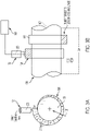
FIG. 1 is a block diagram of a shaft monitoring system configured to monitor a shaft according to a non-limiting embodiment of the present disclosure; -
FIG. 2 is a block diagram of a proximity sensor monitoring a first position of target element coupled to a shaft according to a non-limiting embodiment of the present disclosure; -
FIG. 3A is a front-view of a target element coupled to a shaft according to a non-limiting embodiment of the present disclosure; -
FIG. 3B is a side-view of the target element shown inFIG. 3A according to a non-limiting embodiment of the present disclosure; -
FIG. 4 is a block diagram of a proximity sensor monitoring a second position of a target element included on a shaft according to a non-limiting embodiment of the present disclosure; -
FIG. 5 is a diagram of a signal output by the proximity sensor in response to monitoring the target element rotating in a first direction according to a non-limiting embodiment of the present disclosure; -
FIG. 6 is a diagram of a signal output by the proximity sensor in response to monitoring the target element rotating in a second direction according to a non-limiting embodiment of the present disclosure; -
FIG. 7A is a first side-view of a target element coupled to a shaft according to a non-limiting embodiment of the present disclosure; -
FIG. 7B is a front-view of the target element shown inFIG. 7A according to a non-limiting embodiment of the present disclosure; -
FIG. 7C is an opposing side-view of the target element shown inFIGS. 7A and 7B according to a non-limiting embodiment of the present disclosure; -
FIG. 8 is a diagram of a signal output by the proximity sensor in response to monitoring the target element shown inFIGS. 7A, 7B and 7C according to a non-limiting embodiment of the present disclosure; -
FIG. 9 is a side-view of a target element coupled to a shaft according to a non-limiting embodiment of the present disclosure; -
FIG. 10 is a diagram of a signal output by the proximity sensor in response to monitoring the target element shown inFIG. 9 according to a non-limiting embodiment of the present disclosure; -
FIG. 11 is a flow diagram illustrating a method of determining a rotational position of a shaft according to a non-limiting embodiment of the present disclosure; and -
FIG. 12 is a flow diagram illustrating a method of determining position, speed and direction of a rotating shaft according to a non-limiting embodiment of the present disclosure. - The diagrams depicted herein are illustrative. There can be many variations to the diagram or the operations described therein without departing from the spirit of the invention. For instance, the actions can be performed in a differing order or actions can be added, deleted or modified. Also, the term "coupled", and variations thereof describes having a communications path between two elements and does not imply a direct connection between the elements with no intervening elements/connections between them. All of these variations are considered a part of the specification.
- For the sake of brevity, conventional techniques related to making and using aspects of the invention may or may not be described in detail herein. In particular, various aspects of computing systems and specific computer programs to implement the various technical features described herein are well known. Accordingly, in the interest of brevity, many conventional implementation details are only mentioned briefly herein or are omitted entirely without providing the well-known system and/or process details.
- A wide-variety of devices have traditionally been used to measure the rotational position of a shaft such as, for example, rotary encoders, rotary-optical encodes (sometimes simply referred to as optical encoders), resolvers that determine position based on sine and cosine output voltages, and synchro encoders that determine position based on relative voltage magnitudes between three output wires. Rotary encoders such as incremental encoders and absolute optical encoders, for example, have been traditionally employed with shafts to indicate an angular positional range of a rotated shaft. Incremental encoders generate a certain number of pulses per revolution with each pulse corresponding to a defined resolution. Every time an incremental encoder is switched on the pulse is counted from zero. In other words the position is not stored and a 'reset or reference' position must be obtained before the encoder begins counting again. Consequently, an incremental encoder can measure the change in position but not the absolute position.
- An absolute optical encoder maintains position information when power is removed from the encoder. The relationship between the encoder value and the physical position of the controlled machinery is set at assembly and the system does not need to return to a calibration point to maintain position accuracy. However, absolute optical encoders require multiple code rings with various binary weightings which provide a data word representing the absolute position of the encoder within one revolution. Additional code wheels and gears must be implemented to increase the precision of the encoder, which in turn increases overall costs and weight.
- Incremental encoders and absolute optical encoders both output a binary encoding signal that provides information associated with the shaft. In this case of an incremental encoder, the output binary encoding signal provides information about the motion of the shaft, but provides no information pertaining to a specific position and/or direction of the shaft. The output binary encoding signal of an absolute optical encoder may provide a general angular range of the shaft, but provides no information pertaining to a specific direction of the shaft.
- Various non-limiting embodiments of the disclosure provide a shaft monitoring system that employs a proximity sensor configured to measure rotation of a proximity sensor target element (hereinafter referred to a target element) coupled to a rotating shaft. The target element includes a series of individual target sections that are sensed by the proximity sensor as the shaft rotates. The profiles and/or volumes of the individual target sections continuously change as the target element extends from the first individual target section included in the series to the last individual target section. The volume of each sensed target section with respect to the proximity sensor produces a different inductance as indicated by the proximity sensor output signal. Over a full rotation of the shaft, the proximity sensor output signal itself not only indicates a position of the shaft, but also can indicate both the rotational direction and rotational speed of the shaft.
- Turning now to
FIG. 1 , ashaft monitoring system 100 is illustrated according to a non-limiting embodiment of the present disclosure. Theshaft monitoring system 100 includes aproximity sensor 102 configured to monitor atarget element 104 coupled to ashaft 106, and asignal processing system 108 configured to process the output signal generated by theproximity sensor 102. - The
signal processing system 108 includes an inductance-to-voltage converter (IVC) 110, an analog-to-digital converter (ADC) 112 and acontroller 114. TheIVC 110 receives a proximity sensor output signal indicative of a measured inductance between the proximity sensor and thetarget element 104, and converts the measured inductance into an analog voltage signal. TheADC 112 receives the analog voltage signal and converts it into a digital signal indicative of the measured inductance. Thecontroller 114 processes the digital signal to determine the angular position of the shaft (e.g., degree of rotation), the speed of the shaft (e.g., rotations per minute (RPM)), and rotational direction of the shaft (e.g., clockwise rotation or counter clockwise rotation). The speed of the shaft and rotational direction of the shaft together can define a velocity of the shaft. Accordingly, the proximity sensor output signal itself can provide the angular position of the shaft, the speed of the shaft, and the rotational direction of the shaft without requiring additional sensors and/or software algorithms to determine shaft speed and shaft direction. - The
proximity sensor 102 can be positioned near theshaft 106, which includes the proximity sensor target element 104 (hereinafter referred to a target element 104) coupled thereto. Theproximity sensor 102 includes aninductive sensing element 103, while thetarget element 104 is formed from various materials including, but not limited to, metal and ferrous materials. Energizing the inductive sensing element 103 (e.g., using an alternating current (AC) signal) induces a magnetic field, which can interact with thetarget element 104. For example, a change in distance between theproximity sensor 102 and thetarget element 104 varies the strength of the magnetic field, and in turn varies the inductance of thesensing element 103. - With this in mind, the
target element 104 can be coupled to theshaft 106 in a manner that allows the distance between theproximity sensor 102 and thetarget element 104 to change as theshaft 106 rotates. Such an arrangement causes the inductance of thesensing element 103 to also change as theshaft 106 rotates, thereby producing a relationship between the measured inductance indicated by the proximity sensor output signal and the rotational position of theshaft 106. In this manner, the proximity sensor output signal alone can be processed by thesignal processing system 108 to determine the shaft position, shaft speed and shaft direction. - Turning to
FIGS. 2-6 , operating concepts of theproximity sensor 102 and atarget element 104 are illustrated according to non-limiting embodiments of the present disclosure. In the examples described with respect to the various embodiments of the application, thetarget element 104 comprises a ferromagnetic material and is illustrated as being coupled to an outer surface of theshaft 106. In one or more non-limiting embodiments, thetarget element 104 also extends 360 degrees about a shaft axis from one target element end (e.g., a first target section) to an opposite target element end (e.g., a last target section) to define circumferential profile. It should be appreciated, however, that the inventive concept is not limited to the aforementioned arrangement and that other arrangements of thetarget element 104 andshaft 106 can be implemented without departing from the scope of the invention. - The
proximity sensor 102 includes ahousing 200 that contains an inductive coil 202 (sometimes referred to as a "winding") that is wound around acore 204. Theinductive coil 202 can be formed from various materials including, but not limited to metal. Thecore 204 extends along acenter axis 205 to define a core length (L), and can be formed from various materials including, but not limited to metal, ferrite, and ferromagnetic material. Although the inductive coil is illustrated as having three turns, theproximity sensor 102 is not limited thereto and more or less turns can be implemented without departing from the scope of the invention. - The
inductive coil 202 includes opposing first and second ends 208 and 210 that are electrically connected to an alternating current (AC)source 206. Accordingly, theAC source 206 delivers AC current through theinductive coil 202 so as to induce an electromagnetic field. The first and second ends 208 and 210 are also electrically connected to thesignal processing system 108 viaterminals coil 202 is applied toterminals signal processing system 108. In this manner, the proximity sensor output signal can be processed by thesignal processing system 108 to determine the shaft position, shaft speed and shaft direction as described herein. -
FIGS. 3A and 3B illustrate an example of thetarget element 104 in greater detail. Thetarget element 104 is formed on an outer surface of theshaft 106, which extends along therotational center axis 107 to define a shaft length (Ls). Thetarget element 104 has a varying volume, which can be sensed by theproximity sensor 102 as theshaft 106 rotates. - In a non-limiting embodiment, the
target element 104 can include a series of target sections that can be sensed by theproximity sensor 102. Although sixteentarget sections 216 are illustrated (labeled 1 through 16), it should be appreciated that thetarget element 104 can include more orless target sections 216 without departing from the scope of the invention.Distinct target sections 216 are shown for ease of illustration. It should be appreciate that thetarget sections 216 can be integrally formed to define a singlecontiguous target element 104 having a changing volume as described herein. - The profiles (e.g., height, width and/or volume) of the
individual target sections 216 continuously change as thetarget element 104 extends from the first individual target section 216 (e.g., section 1) located at one end of thetarget element 104 to the last individual target section 216 (e.g., section 16) located at the opposite end of thetarget element 104. In a non-limiting embodiment, thefirst target element 216 can be formed to have a minimum volume of thetarget element 104 while thelast target element 216 can be formed to have a maximum volume of thetarget element 104. Accordingly, thetarget element 104 will present an ambiguous position once per 360 degrees, which is when thefirst target element 216 or thelast target element 216 is aligned beneath theproximity sensor 102. - The profile of each sensed
target section 216 with respect to theproximity sensor 102 produces a different measured inductance, which is reflected by the proximity sensor output signal delivered to thesignal processing system 108. In a non-limiting embodiment, thetarget element 104 is also shown as having an inclined or ramp profile. It should be appreciated, however, that thetarget element 104 can have a different profile. For example, thetarget element 104 can have a step-like profile that include a series of steps that change in volume from the first section (e.g., section 1) to the last section (e.g., section 16). - In one or more non-limiting embodiments, a
dummy target element 105 can be coupled to the outer surface of theshaft 106 and adjacent to thetarget element 104 as shown inFIG. 3B . Thedummy target element 105 can have a mirror image profile with respect to thetarget element 104. In this manner, thedummy target element 105 can serve as a counterweight to thetarget element 104 and improve the balance of therotating shaft 106. - Referring collectively to
FIGS. 2 ,3A and 3B , theproximity sensor 102 is illustrated measuring thetarget element 104 while theshaft 106 is in a first position. According to a non-limiting embodiment, theproximity sensor 102 is positioned such that thesensor axis 205 is perpendicular with respect to therotational center axis 107 of theshaft 106 and a first target section 216 (e.g., target section 1) is aligned with theaxis 205 of theproximity sensor 102. In this example,target section 1 has a profile of being the lowest-volume target section 216 or thetarget section 216 with the lowest height (H) (and the largest distance from thesensor 102 when located in proximity of the sensor 102) extending from the surface of theshaft 106 and perpendicular to therotational center axis 107. Accordingly, a maximum distance is defined between theproximity sensor 102 and thetarget element 104 such that thecoil 202 realizes a minimum inductance. - Turning to
FIG. 4 , theproximity sensor 102 is illustrated measuring thetarget element 104 while theshaft 106 is rotated counter-clockwise (in almost a full rotation) into a second position from the first position shown inFIG. 2 . While in the second position, a second target section 216 (e.g., target section 16) is aligned with theaxis 205 of theproximity sensor 102. In this example,target section 16 has a profile of being the largest-volume target section 216 or thetarget section 216 with the greatest height extending from the surface of theshaft 106. Accordingly, a minimum distance is defined between theproximity sensor 102 and thetarget element 104 such that thecoil 202 realizes a maximum inductance. -
FIG. 5 illustrates the proximitysensor output signal 500 generated by theproximity sensor 102 in response to measuring the counter-clockwise rotation of thetarget element 104 from 0 degrees (0°) to 360 degrees (360°) as described above with respect toFIGS. 2 and4 . At 0°, the lowest volume target section 216 (e.g., section 1) of thetarget element 104 is aligned with theaxis 205 such that the distance between theproximity sensor 102 and thetarget element 104 is at its maximum. As a result, the inductance of thecoil 202 is at its minimum (Min). As theshaft 106 rotates counterclockwise, thetarget sections 216 increase in volume (e.g., height). Accordingly, the inductance of thecoil 202 gradually increases until the largest volume target section 216 (e.g., section 16) of thetarget element 104 is aligned with theaxis 205. As a result, the inductance of thecoil 202 is at its maximum (Max), thereby defining a proximitysensor output signal 500 having a positive slope. - It should be appreciated that the proximity
sensor output signal 500 illustrated inFIG. 5 is generated using atarget element 104 comprising a ferro-magnetic material and acoil 202 of theproximity sensor 102 excited at a low-frequency (e.g.,: frequency where the effects of magnetic permeability is greater than the effects of eddy current). In another non-limiting embodiment, atarget element 104 comprising a non-magnetic metallic material and acoil 202 excited at a low-frequency (e.g.,: frequency where the effects of magnetic permeability is greater than the effects of eddy current) can result in a measured inductance that decreases as theshaft 106 rotates counterclockwise. As a result, theoutput signal 500 will have a negative slope. - In another embodiment, the
target element 104 can comprise a ferromagnetic material and thecoil 202 of theproximity sensor 102 can be excited at a highfrequency (e.g., frequency where the effects of magnetic permeability is less than the effects of eddy current). Accordingly, the measured inductance may decreases as theshaft 106 rotates counter-clockwise. As a result, theoutput signal 500 will have a negative slope. -
FIG. 6 illustrates a proximitysensor output signal 500 generated by theproximity sensor 102 in response to measuring a clockwise rotation of thetarget element 104 from 0° to 360° as described above with respect toFIGS. 3 and4 . At 0°, the largest volume target section 216 (e.g., section 16) of thetarget element 104 is aligned with theaxis 205 such that the distance between theproximity sensor 102 and thetarget element 104 is at its minimum. As a result, the inductance of thecoil 202 is at its maximum (Max). As theshaft 106 rotates clockwise, thetarget sections 216 decrease in volume (e.g., height). Accordingly, the inductance of thecoil 202 gradually decreases u the lowest volume target section 216 (e.g., section 1) of thetarget element 104 is aligned with theaxis 205. As a result, the inductance of thecoil 202 is at its minimum (Min), thereby defining a proximitysensor output signal 500 having a negative slope. - As described herein, the proximity
sensor output signal 500 alone can be utilized to determine position, speed and direction of theshaft 106. For instance, the proximitysensor output signal 500 can be converted into a digital signal using the ADC 112 (seeFIG. 1 ), which is then processed by thecontroller 114. Thecontroller 114 can compute the rotational position of theshaft 106 based on the amplitude of the proximitysensor output signal 500. For example, each rotational angle of the shaft can be associated with a inductance or inductance range. In at least one non-limiting embodiment, a unique inductance is associated with each angle, notwithstanding the ambiguity that may be present at the interface between minimum volume portion of the target element and the maximum volume portion of thetarget element 104. This ambiguity can be resolved using a software algorithm programmed in thecontroller 114. - Accordingly, a given amplitude proximity
sensor output signal 500 can indicate a particular rotational angle, i.e., position of theshaft 106. Thecontroller 114 can compute the speed of theshaft 106 based on the period of the proximitysensor output signal 500. That is, the change in position of the change in time indicates the rotational speed of theshaft 106. Lastly, thecontroller 114 can compute the direction of theshaft 106 based on the slope of the proximitysensor output signal 500. For example, a proximitysensor output signal 500 having a positive slope (seeFIG. 5 ) indicates theshaft 106 is rotating in a counter-clockwise direction. On the other hand, proximitysensor output signal 500 having a negative slop (seeFIG. 6 ) indicates theshaft 106 is rotating in a clockwise direction. - Referring now to
FIGS, 7A, 7B and 7C , an arrangement of aproximity sensor 102 and atarget element 700 coupled to ashaft 106 is illustrated according to another non-limiting embodiment. Thetarget element 700 is formed on an outer surface of theshaft 106, which extends along arotational center axis 107 to define a shaft length (Ls). Thetarget element 104 includes a series ofindividual target sections 702 that can be individually sensed by theproximity sensor 102 as theshaft 106 rotates. Although sixteentarget sections 702 are illustrated (labeled 1 through 16), it should be appreciated that thetarget element 700 can include more orless target sections 702 without departing from the scope of the invention. As described herein,distinct sections 702 are shown for ease of illustration. It should be appreciated that thesections 702 can be integrally formed to define a singlecontiguous target element 700 having a changing volume. - The profiles of the
individual target sections 702 continuously change as thetarget element 700 extends from the first individual target section (e.g., section 1) to the last individual target section (e.g., section 16). In this example, the changing profiles include varying widths (w) of theindividual target sections 702. Although the first target section 702 (section 1) is shown as having the smallest width (w) while the last target section 702 (section 16) is shown as having the largest width (w), it should be appreciated that the first target section 702 (section 1) can have the largest width (w) while the last target section 702 (section 16) can have the smallest with without departing from the scope of the invention. - In one or more non-limiting embodiments, a
dummy target element 704 can be coupled to the outer surface of theshaft 106 and adjacent to thetarget element 700 as shown inFIGS. 7A and 7C . Thedummy target element 704 can have a mirror image profile with respect to thetarget element 700. In this manner, thedummy target element 704 can serve as a counterweight to thetarget element 700 and improve the balance of therotating shaft 106. - The widths of the
individual target sections 702 extend parallel to therotational center axis 107 of theshaft 106. As theshaft 106 rotates,target sections 702 of varying widths (and thus varying volumes) are aligned with thecenter axis 205. Accordingly, each sensedtarget section 702 produces a different measured inductance, which is reflected by the proximity sensor output signal delivered to thesignal processing system 108. As described herein, a unique inductance is associated with each angle, notwithstanding the ambiguity that may be present at the interface between minimum volume portion of the target element and the maximum volume portion of thetarget element 104. This ambiguity can be resolved using a software algorithm programmed in thecontroller 114. -
FIG. 8 illustrates the proximitysensor output signal 800 generated by theproximity sensor 102 in response to measuring the clockwise rotation of thetarget element 700 from 0° to 360° as described above with respect toFIGS. 7A-7C . At 0°, the lowest volume target section 702 (e.g., section 1) of thetarget element 700 is aligned with thecenter axis 205. As a result, the inductance of thecoil 202 is at its minimum (Min). As theshaft 106 rotates clockwise, thetarget sections 702 increase in width and volume. Accordingly, the inductance of thecoil 202 gradually increases until the largest volume target section 702 (e.g., section 16) of thetarget element 700 is aligned with thecenter axis 205. As a result, the inductance of thecoil 202 is at its maximum (Max), thereby defining a proximitysensor output signal 500 having a positive slope. Although the proximitysensor output signal 800 is described in terms of a clockwise rotation of thetarget element 700, thetarget element 700 can be rotated counterclockwise to generate a proximitysensor output signal 800 having a negative slope without departing from the scope of the invention. - It should be appreciated that the proximity
sensor output signal 800 illustrated inFIG. 8 is generated using atarget element 700 comprising a ferro-magnetic material and acoil 202 of theproximity sensor 102 excited at a low-frequency (e.g.,: frequency where the effects of magnetic permeability is greater than the effects of eddy current). In another non-limiting embodiment, atarget element 700 comprising a non-magnetic metallic material and acoil 202 excited at a low-frequency (e.g.,: frequency where the effects of magnetic permeability is greater than the effects of eddy current) can result in a measured inductance that decreases as theshaft 106 rotates counterclockwise. As a result, theoutput signal 700 will have a negative slope. - In another embodiment, the
target element 700 can comprise a ferromagnetic material and thecoil 202 of theproximity sensor 102 can be excited at a highfrequency (e.g., frequency where the effects of magnetic permeability is less than the effects of eddy current). Accordingly, the measured inductance may decreases as theshaft 106 rotates counter-clockwise. As a result, theoutput signal 700 will have a negative slope. - Turning now to
FIG. 9 , an arrangement of aproximity sensor 102 and atarget element 900 coupled to ashaft 106 is illustrated according to another non-limiting embodiment. Thetarget element 900 is formed on an end of theshaft 106 and is aligned with theshaft center axis 107. Accordingly, both theshaft 106 and thetarget element 900 rotate about thecenter axis 107. - The
target element 900 includes a series ofindividual target sections 902 that can be individually sensed by theproximity sensor 102 as theshaft 106 rotates. Although 12target sections 902 are illustrated (labeled 1 through 12), it should be appreciated that thetarget element 900 can include more orless target sections 902 without departing from the scope of the invention. As described herein,distinct sections 902 are shown for ease of illustration. It should be appreciate that thetarget sections 902 can be integrally formed to define a singlecontiguous target element 900 having a changing volume. - In at least one non-limiting embodiment shown in
FIG. 9 , theproximity sensor 102 is positioned such that thesensor axis 205 is parallel with respect to therotational center axis 107 of theshaft 106. However, theproximity sensor 102 is offset with respect to therotational center axis 107 such that it is substantially aligned with atarget center line 904 that extends along the centers of thetarget sections 902. In this example, a first target section 902 (e.g., target section 12) is aligned with theaxis 205 of theproximity sensor 102 and has a profile of being the largest-volume target section 216 or thetarget section 216 with the greatest width (w) extending from the surface of theshaft 106 and parallel with therotational center axis 107. Accordingly, a minimum distance is defined between theproximity sensor 102 and the target element 902 (e.g., target section 12) such that thecoil 202 realizes a maximum inductance. -
FIG. 10 illustrates the proximitysensor output signal 1000 generated by theproximity sensor 102 in response to measuring the counter-clockwise rotation of thetarget element 900 from 0° to 360° as described above with respect toFIG. 9 . At 0°, the lowest volume target section 902 (e.g., section 1) of thetarget element 902 is aligned with thecenter axis 205 of theproximity sensor 102. As a result, the inductance of thecoil 202 is at its minimum (Min). As theshaft 106 rotates clockwise, thetarget sections 902 increase in volume. Accordingly, the inductance of thecoil 202 gradually increases until the largest volume target section 902 (e.g., section 12) of thetarget element 900 is aligned with thecenter axis 205. As a result, the inductance of thecoil 202 is at its maximum (Max), thereby defining a proximitysensor output signal 1000 having a positive slope. Although the proximitysensor output signal 1000 is described in terms of a clockwise rotation of thetarget element 900, thetarget element 900 can be rotated counter-clockwise to generate a proximitysensor output signal 1000 having a negative slope without departing from the scope of the invention. - It should be appreciated that the proximity
sensor output signal 1000 illustrated inFIG. 10 is generated using atarget element 900 comprising a ferromagnetic material and acoil 202 of theproximity sensor 102 excited at a low-frequency (e.g.,: frequency where the effects of magnetic permeability is greater than the effects of eddy current). In another non-limiting embodiment, atarget element 900 comprising a non-magnetic metallic material and acoil 202 excited at a low-frequency (e.g., frequency where the effects of magnetic permeability is greater than the effects of eddy current) can result in a measured inductance that decreases as theshaft 106 rotates clockwise. As a result, theoutput signal 900 will have a negative slope. - In another embodiment, the
target element 900 can comprise a ferromagnetic material and thecoil 202 of theproximity sensor 102 can be excited at a highfrequency (e.g., frequency where the effects of magnetic permeability is less than the effects of eddy current). Accordingly, the measured inductance may decreases as theshaft 106 rotates clockwise. As a result, theoutput signal 1000 will have a negative slope. - With reference now to
FIG. 11 , a method of determining position of a shaft is illustrated according to a non-limiting embodiment of the present disclosure. The method begins atoperation 1100 and at operation 1102 a proximity sensor is positioned near a target element coupled to a shaft. Atoperation 1104, the proximity sensor measures the inductance corresponding to a given target section that is aligned with the proximity sensor. Atoperation 1106, the proximity sensor generates a proximity sensor output signal based a measured inductance corresponding to a given target section included in target element that is coupled to the shaft. Atoperation 1108, the shaft position is determined based on the proximity sensor output signal, and the method ends atoperation 1110. - Turning to
FIG. 12 , a method of determining position, speed and direction of a rotating shaft is illustrated according to a non-limiting embodiment of the present disclosure. The method begins atoperation 1200 and at operation 1202 a proximity sensor is positioned near a target element coupled to a shaft. Atoperation 1204, the shaft is rotated (i.e., in a clockwise direction or counter-clockwise). Atoperation 1206, the proximity sensor measures the inductance corresponding to a given target section that is aligned with the proximity sensor. Atoperation 1208, the proximity sensor generates a proximity sensor output signal based on a sequence of measured inductances corresponding to rotated target sections rotating along with the shaft. Atoperation 1210, the shaft position, the shaft direction and/or the shaft speed is determined based on the proximity sensor output signal, and the method returns tooperation 1204 to rotate the shaft. Atoperation 1212, the shaft position, the shaft direction and/or the shaft speed is reported, e.g., to a display screen or a graphic user interface (GUI). As the shaft continues rotation (e.g., clockwise or counter-clockwise), the changed shaft position, shaft direction and/or the shaft speed can be actively reported in real-time. - As described herein, various non-limiting embodiments of the disclosure provide a shaft monitoring system that employs a proximity sensor configured to measure rotation of a proximity sensor target element (hereinafter referred to a target element) coupled to a rotating shaft. The target element includes a series of individual target sections that are sensed by the proximity sensor as the shaft rotates. The profiles and/or volumes of the individual target sections and/or distance between the target sections and the proximity sensor continuously change as the target element extends from the first individual target section included in the series to the last individual target section. The volume of each sensed target section with respect to the proximity sensor and/or the distance between each target section and the proximity sensor produces a different inductance as indicated by the proximity sensor output signal. Over a full rotation of the shaft, the proximity sensor output signal itself not only indicates a position of the shaft, but also can indicate both the rotational direction and rotational speed of the shaft.
- The term "about" is intended to include the degree of error associated with measurement of the particular quantity based upon the equipment available at the time of filing the application. For example, "about" can include a range of ± 8% or 5%, or 2% of a given value.
- The terminology used herein is for the purpose of describing particular embodiments only and is not intended to be limiting of the present disclosure. As used herein, the singular forms "a", "an" and "the" are intended to include the plural forms as well, unless the context clearly indicates otherwise. It will be further understood that the terms "comprises" and/or "comprising," when used in this specification, specify the presence of stated features, integers, steps, operations, elements, and/or components, but do not preclude the presence or addition of one or more other features, integers, steps, operations, element components, and/or groups thereof.
- Various embodiments of the invention are described herein with reference to the related drawings. Alternative embodiments of the invention can be devised without departing from the scope of this invention. Various connections and positional relationships (e.g., over, below, adjacent, etc.) are set forth between elements in the following description and in the drawings. These connections and/or positional relationships, unless specified otherwise, can be direct or indirect, and the present invention is not intended to be limiting in this respect. Accordingly, a coupling of entities can refer to either a direct or an indirect coupling, and a positional relationship between entities can be a direct or indirect positional relationship. Moreover, the various tasks and process steps described herein can be incorporated into a more comprehensive procedure or process having additional steps or functionality not described in detail herein.
- The following definitions and abbreviations are to be used for the interpretation of the claims and the specification. As used herein, the terms "comprises," "comprising," "includes," "including," "has," "having," "contains" or "containing," or any other variation thereof, are intended to cover a non-exclusive inclusion. For example, a composition, a mixture, process, method, article, or apparatus that comprises a list of elements is not necessarily limited to only those elements but can include other elements not expressly listed or inherent to such composition, mixture, process, method, article, or apparatus.
- Additionally, the term "exemplary" is used herein to mean "serving as an example, instance or illustration." Any embodiment or design described herein as "exemplary" is not necessarily to be construed as preferred or advantageous over other embodiments or designs. The terms "at least one" and "one or more" may be understood to include any integer number greater than or equal to one, i.e. one, two, three, four, etc. The terms "a plurality" may be understood to include any integer number greater than or equal to two, i.e. two, three, four, five, etc. The term "connection" may include both an indirect "connection" and a direct "connection."
- While the present disclosure has been described with reference to an exemplary embodiment or embodiments, it will be understood by those skilled in the art that various changes may be made without departing from the scope of the invention as defined by the claims. In addition, many modifications may be made to adapt a particular situation or material to the teachings of the present disclosure without departing from the scope of the invention. Therefore, it is intended that the present disclosure not be limited to the particular embodiment disclosed as the best mode contemplated for carrying out this present disclosure, but that the present disclosure will include all embodiments falling within the scope of the claims.
Claims (15)
- A shaft monitoring system comprising:a rotatable shaft (106) including a target element (104) coupled thereto that rotates along with the shaft;a proximity sensor (102) located adjacent to the target element, the proximity sensor configured to measure an inductance of the target element based on one or both of a volume of the target element and a distance between the target element and the proximity sensor, and to generate a proximity sensor output signal based on the measured inductance; anda signal processing system (108) in signal communication with the proximity sensor, the signal processing system configured to determine at least one of a position of the shaft, a rotational speed of the shaft, and a rotational direction of the shaft based on the proximity sensor output signal.
- The shaft monitoring system of claim 1, wherein the volume of the target element (104) continuously changes as the target element extends from a first end of the target element to an opposing second end of the target element.
- The shaft monitoring system of claim 2, wherein a proximity of the volume with respect to the proximity sensor (102) produces a respective measured inductance, and the respective measured inductance corresponds to a respective rotational position of the shaft.
- The shaft monitoring system of claim 3, wherein rotating the shaft (106) rotates the target element (104) and varies the volume of the target element aligned with the proximity sensor (108) to change the measured inductance, and optionally wherein the position of the shaft, the rotational speed of the shaft, and the rotational direction are determined in response to rotating the shaft.
- The shaft monitoring system of claim 2, 3 or 4, wherein a minimum volume of the target element is at the first end and a maximum volume is located at the second end.
- The shaft monitoring system of claim 5, wherein the target element extends three-hundred and sixty (360) degrees from the first end to the second end to define a circumferential profile.
- The shaft monitoring system of any preceding claim, wherein the distance changes based on a rotational position of the shaft.
- The shaft monitoring system of claim 7, wherein rotating the shaft produces different distances between the target element and the proximity sensor to produce different measured inductances, and optionally wherein each of the different measured inductances corresponds to a respective rotational position of the shaft.
- A method of monitoring a rotatable shaft, the method comprising:positioning a target element (104) coupled to a rotatable shaft (106) a distance away from a proximity sensor (102);measuring, via the proximity sensor, an inductance based on one or both of a volume of the target element and a distance between the target element and the proximity sensor;generating a proximity sensor output signal based on the measured inductance; anddetermining, via a signal processing system (108) in signal communication with the proximity sensor, at least one of a position of the shaft, a rotational speed of the shaft, and a rotational direction of the shaft based on the proximity sensor output signal.
- The method of claim 9, wherein the volume of the target element continuously changes as the target element extends from a first end of the target element to an opposing second end of the target element.
- The method of claim 10, further comprising:producing a respective measured inductance based on a proximity of the volume with respect to the proximity sensor; anddetermining a respective rotational position of the shaft based on the respective measured inductance.
- The method of claim 11, further comprising:rotating the shaft so as to rotate the target element;and varying the volume of the target element aligned with the proximity sensor in response to rotating the target element to change the measured inductance, and optionally further comprising determine the position of the shaft, the rotational speed of the shaft, and the rotational direction in response to rotating the shaft.
- The method of any of claims 9 to 12, wherein a minimum volume of the target element is at the first end and a maximum volume is located at the second end, and optionally wherein the target element extends three-hundred and sixty (360) degrees from the first end to the second end to define a circumferential profile.
- The method of any of claims 9 to 13, further comprising changing the distance based on a rotational position of the shaft.
- The method of claim 14, further comprising producing different distances between the target element and the proximity sensor in response to rotating the shaft, and producing different measured inductances based on the different distances, and optionally further comprising determining a respective rotational position of the shaft based on a respective different measured inductance.
Applications Claiming Priority (1)
| Application Number | Priority Date | Filing Date | Title |
|---|---|---|---|
| US17/229,235 US11761794B2 (en) | 2021-04-13 | 2021-04-13 | Proximity sensor to sense rotating shaft position and velocity |
Publications (2)
| Publication Number | Publication Date |
|---|---|
| EP4075100A1 true EP4075100A1 (en) | 2022-10-19 |
| EP4075100B1 EP4075100B1 (en) | 2024-12-11 |
Family
ID=81325715
Family Applications (1)
| Application Number | Title | Priority Date | Filing Date |
|---|---|---|---|
| EP22166831.2A Active EP4075100B1 (en) | 2021-04-13 | 2022-04-05 | Proximity sensor to sense rotating shaft position and velocity |
Country Status (4)
| Country | Link |
|---|---|
| US (1) | US11761794B2 (en) |
| EP (1) | EP4075100B1 (en) |
| BR (1) | BR102022006571A2 (en) |
| CA (1) | CA3154739A1 (en) |
Cited By (1)
| Publication number | Priority date | Publication date | Assignee | Title |
|---|---|---|---|---|
| EP4632329A1 (en) * | 2024-04-12 | 2025-10-15 | RTX Corporation | Proximity rotational angular measurement |
Families Citing this family (2)
| Publication number | Priority date | Publication date | Assignee | Title |
|---|---|---|---|---|
| US11525870B2 (en) * | 2017-10-05 | 2022-12-13 | The Charles Stark Draper Laboratory, Inc. | Electromagnetic gradiometers |
| US12052944B2 (en) * | 2020-11-03 | 2024-08-06 | Harvest International, Inc. | Rotational speed sensors for agricultural seed planter |
Citations (4)
| Publication number | Priority date | Publication date | Assignee | Title |
|---|---|---|---|---|
| JPH0626808A (en) * | 1992-07-09 | 1994-02-04 | Ebara Corp | Sensor target |
| WO2014053835A2 (en) * | 2012-10-02 | 2014-04-10 | Mark Anthony Howard | Detector |
| US20150211895A1 (en) * | 2013-03-04 | 2015-07-30 | Texas Instruments Incorporated | Inductive sensing including inductance multiplication with series connected coils |
| US20170292628A1 (en) * | 2014-09-15 | 2017-10-12 | Flowserve Management Company | Sensors for valve systems and related assemblies, systems and methods |
Family Cites Families (20)
| Publication number | Priority date | Publication date | Assignee | Title |
|---|---|---|---|---|
| US4142153A (en) | 1977-02-17 | 1979-02-27 | Sperry Rand Corporation | Tachometer for measuring speed and direction of shaft rotation with a single sensing element |
| US5367257A (en) | 1992-05-14 | 1994-11-22 | Garshelis Ivan J | Non-contact, magnetic sensor for determining direction of motion and velocity of a movable member |
| DE4233549A1 (en) | 1992-10-01 | 1994-04-21 | Brose Fahrzeugteile | Detecting RPM and rotation direction of rotary drive, e.g. window lifter of motor vehicle - using signal generating or altering element connected to rotary drive and supplying detecting sensor and electronic evaluation unit |
| US5371460A (en) | 1992-09-21 | 1994-12-06 | Caterpillar Inc. | Speed and direction sensor for a rotating shaft having a rotor with teeth of alternating widths |
| SE502358C2 (en) * | 1993-09-24 | 1995-10-09 | Nira Automotive Ab | Steering angle sensor for a motor vehicle |
| US5977765A (en) | 1997-12-05 | 1999-11-02 | Ford Global Technologies, Inc. | Speed, direction, and acceleration sensor for a rotating shaft having a rotor with teeth having unequal spacing |
| US6969987B2 (en) * | 2003-10-16 | 2005-11-29 | Aaron Schwartzbart | Hybrid inductive sensor |
| US7469604B2 (en) | 2005-10-21 | 2008-12-30 | Stoneridge Control Devices, Inc. | Sensor system including a magnetized shaft |
| US7340951B2 (en) * | 2005-11-04 | 2008-03-11 | David S. Nyce | Distributed impedance sensor |
| DE202006009621U1 (en) * | 2006-06-20 | 2006-10-12 | Trw Automotive Safety Systems Gmbh | Absolute angle determining device e.g. for rotation of axis of rotation e.g. for measuring absolute angle of rotation of steering wheel, has measuring instrument for measurement of angle of rotation in reduced measuring range |
| ATE497148T1 (en) * | 2007-08-31 | 2011-02-15 | Pepperl & Fuchs | INDUCTIVE TRANSDUCER, ENCODING DEVICE AND METHOD FOR DETERMINING A POSITION OF A FIRST OBJECT RELATIVE TO A SECOND OBJECT |
| US8203331B2 (en) * | 2009-02-17 | 2012-06-19 | Goodrich Corporation | Non-contact sensor system and method for selection determination |
| WO2011154786A1 (en) * | 2010-06-10 | 2011-12-15 | パナソニック電工株式会社 | Position sensor |
| US8203334B2 (en) | 2010-10-28 | 2012-06-19 | General Electric Company | Magnetically spirally encoded shaft for measuring rotational angel, rotational speed and torque |
| DE102011053309A1 (en) * | 2011-09-06 | 2013-03-07 | Balluff Gmbh | Position / displacement measuring system |
| US20130145847A1 (en) | 2011-12-09 | 2013-06-13 | Hamilton Sundstrand Space Systems International, Inc. | Asymmetrical sensor targets |
| US9479134B2 (en) * | 2013-03-04 | 2016-10-25 | Texas Instruments Incorporated | Position detecting system |
| DE102014220454A1 (en) * | 2014-10-09 | 2016-04-14 | Robert Bosch Gmbh | Sensor arrangement for the contactless detection of angles of rotation on a rotating component |
| US10969246B2 (en) * | 2018-07-27 | 2021-04-06 | Samsung Electro-Mechanics Co., Ltd. | Apparatus for sensing rotating device |
| GB201820822D0 (en) | 2018-12-20 | 2019-02-06 | Rolls Royce Plc | Shaft monitoring system |
-
2021
- 2021-04-13 US US17/229,235 patent/US11761794B2/en active Active
-
2022
- 2022-03-31 CA CA3154739A patent/CA3154739A1/en active Pending
- 2022-04-05 BR BR102022006571-3A patent/BR102022006571A2/en unknown
- 2022-04-05 EP EP22166831.2A patent/EP4075100B1/en active Active
Patent Citations (4)
| Publication number | Priority date | Publication date | Assignee | Title |
|---|---|---|---|---|
| JPH0626808A (en) * | 1992-07-09 | 1994-02-04 | Ebara Corp | Sensor target |
| WO2014053835A2 (en) * | 2012-10-02 | 2014-04-10 | Mark Anthony Howard | Detector |
| US20150211895A1 (en) * | 2013-03-04 | 2015-07-30 | Texas Instruments Incorporated | Inductive sensing including inductance multiplication with series connected coils |
| US20170292628A1 (en) * | 2014-09-15 | 2017-10-12 | Flowserve Management Company | Sensors for valve systems and related assemblies, systems and methods |
Cited By (1)
| Publication number | Priority date | Publication date | Assignee | Title |
|---|---|---|---|---|
| EP4632329A1 (en) * | 2024-04-12 | 2025-10-15 | RTX Corporation | Proximity rotational angular measurement |
Also Published As
| Publication number | Publication date |
|---|---|
| BR102022006571A2 (en) | 2022-10-18 |
| EP4075100B1 (en) | 2024-12-11 |
| US20220326051A1 (en) | 2022-10-13 |
| US11761794B2 (en) | 2023-09-19 |
| CA3154739A1 (en) | 2022-10-13 |
Similar Documents
| Publication | Publication Date | Title |
|---|---|---|
| EP4075100B1 (en) | Proximity sensor to sense rotating shaft position and velocity | |
| US10330498B2 (en) | Sensor arrangement for the contactless sensing of angles of rotation on a rotating part | |
| JP6043721B2 (en) | Improved position sensor | |
| US11448524B2 (en) | Multipole magnet for use with a pitched magnetic sensor | |
| US9696183B2 (en) | Angular position detector including a variable reluctance resolver-encoder | |
| KR101410196B1 (en) | Bidirectional magnetic position sensor having field rotation | |
| EP1219005A2 (en) | Tachometer apparatus and method for motor velocity measurement | |
| KR20180115705A (en) | Rotation angle sensor | |
| US9989381B2 (en) | Angle sensor with magnetic patterns | |
| WO2013032525A1 (en) | A system and method for position sensing | |
| JP7242352B2 (en) | A system for determining at least one rotational parameter of a rotating member | |
| EP3151017B1 (en) | Amr speed and direction sensor for use with magnetic targets | |
| WO2014044043A1 (en) | Brushless linear rotary transformer | |
| EP2082193B1 (en) | Angular position measurement device | |
| US20110304324A1 (en) | Magnetic encoder | |
| JP7642183B1 (en) | Multi-rotation angle detection device | |
| JP4047947B2 (en) | Inductive linear position detector | |
| JP4224154B2 (en) | Self-calibration type angle detection device and detection accuracy calibration method | |
| JP7843288B2 (en) | Non-contact position sensor equipped with a permanent magnet, measuring device, and method of applying the non-contact position sensor. | |
| JP7573973B2 (en) | System for determining at least one rotational parameter of a rotating member - Patents.com | |
| US12092493B2 (en) | Arrangement and method for position detection with error detection with a position encoder | |
| US7057364B2 (en) | Actuation system comprising a digital position sensor | |
| JP2005172441A (en) | Angle and angular velocity integrated detector | |
| WO2023068932A1 (en) | Motor system, stepper motor and rotor | |
| Kester | SECTION 6 POSITION AND MOTION SENSORS |
Legal Events
| Date | Code | Title | Description |
|---|---|---|---|
| PUAI | Public reference made under article 153(3) epc to a published international application that has entered the european phase |
Free format text: ORIGINAL CODE: 0009012 |
|
| STAA | Information on the status of an ep patent application or granted ep patent |
Free format text: STATUS: THE APPLICATION HAS BEEN PUBLISHED |
|
| AK | Designated contracting states |
Kind code of ref document: A1 Designated state(s): AL AT BE BG CH CY CZ DE DK EE ES FI FR GB GR HR HU IE IS IT LI LT LU LV MC MK MT NL NO PL PT RO RS SE SI SK SM TR |
|
| STAA | Information on the status of an ep patent application or granted ep patent |
Free format text: STATUS: REQUEST FOR EXAMINATION WAS MADE |
|
| 17P | Request for examination filed |
Effective date: 20230419 |
|
| RBV | Designated contracting states (corrected) |
Designated state(s): AL AT BE BG CH CY CZ DE DK EE ES FI FR GB GR HR HU IE IS IT LI LT LU LV MC MK MT NL NO PL PT RO RS SE SI SK SM TR |
|
| GRAP | Despatch of communication of intention to grant a patent |
Free format text: ORIGINAL CODE: EPIDOSNIGR1 |
|
| STAA | Information on the status of an ep patent application or granted ep patent |
Free format text: STATUS: GRANT OF PATENT IS INTENDED |
|
| INTG | Intention to grant announced |
Effective date: 20240709 |
|
| GRAS | Grant fee paid |
Free format text: ORIGINAL CODE: EPIDOSNIGR3 |
|
| GRAA | (expected) grant |
Free format text: ORIGINAL CODE: 0009210 |
|
| STAA | Information on the status of an ep patent application or granted ep patent |
Free format text: STATUS: THE PATENT HAS BEEN GRANTED |
|
| AK | Designated contracting states |
Kind code of ref document: B1 Designated state(s): AL AT BE BG CH CY CZ DE DK EE ES FI FR GB GR HR HU IE IS IT LI LT LU LV MC MK MT NL NO PL PT RO RS SE SI SK SM TR |
|
| REG | Reference to a national code |
Ref country code: GB Ref legal event code: FG4D |
|
| REG | Reference to a national code |
Ref country code: CH Ref legal event code: EP |
|
| REG | Reference to a national code |
Ref country code: IE Ref legal event code: FG4D |
|
| REG | Reference to a national code |
Ref country code: DE Ref legal event code: R096 Ref document number: 602022008529 Country of ref document: DE |
|
| REG | Reference to a national code |
Ref country code: LT Ref legal event code: MG9D |
|
| PG25 | Lapsed in a contracting state [announced via postgrant information from national office to epo] |
Ref country code: HR Free format text: LAPSE BECAUSE OF FAILURE TO SUBMIT A TRANSLATION OF THE DESCRIPTION OR TO PAY THE FEE WITHIN THE PRESCRIBED TIME-LIMIT Effective date: 20241211 |
|
| PG25 | Lapsed in a contracting state [announced via postgrant information from national office to epo] |
Ref country code: FI Free format text: LAPSE BECAUSE OF FAILURE TO SUBMIT A TRANSLATION OF THE DESCRIPTION OR TO PAY THE FEE WITHIN THE PRESCRIBED TIME-LIMIT Effective date: 20241211 |
|
| PG25 | Lapsed in a contracting state [announced via postgrant information from national office to epo] |
Ref country code: BG Free format text: LAPSE BECAUSE OF FAILURE TO SUBMIT A TRANSLATION OF THE DESCRIPTION OR TO PAY THE FEE WITHIN THE PRESCRIBED TIME-LIMIT Effective date: 20241211 |
|
| REG | Reference to a national code |
Ref country code: NL Ref legal event code: MP Effective date: 20241211 |
|
| PG25 | Lapsed in a contracting state [announced via postgrant information from national office to epo] |
Ref country code: ES Free format text: LAPSE BECAUSE OF FAILURE TO SUBMIT A TRANSLATION OF THE DESCRIPTION OR TO PAY THE FEE WITHIN THE PRESCRIBED TIME-LIMIT Effective date: 20241211 |
|
| PG25 | Lapsed in a contracting state [announced via postgrant information from national office to epo] |
Ref country code: NO Free format text: LAPSE BECAUSE OF FAILURE TO SUBMIT A TRANSLATION OF THE DESCRIPTION OR TO PAY THE FEE WITHIN THE PRESCRIBED TIME-LIMIT Effective date: 20250311 |
|
| PG25 | Lapsed in a contracting state [announced via postgrant information from national office to epo] |
Ref country code: LV Free format text: LAPSE BECAUSE OF FAILURE TO SUBMIT A TRANSLATION OF THE DESCRIPTION OR TO PAY THE FEE WITHIN THE PRESCRIBED TIME-LIMIT Effective date: 20241211 Ref country code: GR Free format text: LAPSE BECAUSE OF FAILURE TO SUBMIT A TRANSLATION OF THE DESCRIPTION OR TO PAY THE FEE WITHIN THE PRESCRIBED TIME-LIMIT Effective date: 20250312 |
|
| PGFP | Annual fee paid to national office [announced via postgrant information from national office to epo] |
Ref country code: FR Payment date: 20250319 Year of fee payment: 4 |
|
| PG25 | Lapsed in a contracting state [announced via postgrant information from national office to epo] |
Ref country code: RS Free format text: LAPSE BECAUSE OF FAILURE TO SUBMIT A TRANSLATION OF THE DESCRIPTION OR TO PAY THE FEE WITHIN THE PRESCRIBED TIME-LIMIT Effective date: 20250311 |
|
| PG25 | Lapsed in a contracting state [announced via postgrant information from national office to epo] |
Ref country code: NL Free format text: LAPSE BECAUSE OF FAILURE TO SUBMIT A TRANSLATION OF THE DESCRIPTION OR TO PAY THE FEE WITHIN THE PRESCRIBED TIME-LIMIT Effective date: 20241211 |
|
| REG | Reference to a national code |
Ref country code: AT Ref legal event code: MK05 Ref document number: 1750696 Country of ref document: AT Kind code of ref document: T Effective date: 20241211 |
|
| PG25 | Lapsed in a contracting state [announced via postgrant information from national office to epo] |
Ref country code: SM Free format text: LAPSE BECAUSE OF FAILURE TO SUBMIT A TRANSLATION OF THE DESCRIPTION OR TO PAY THE FEE WITHIN THE PRESCRIBED TIME-LIMIT Effective date: 20241211 |
|
| PG25 | Lapsed in a contracting state [announced via postgrant information from national office to epo] |
Ref country code: PL Free format text: LAPSE BECAUSE OF FAILURE TO SUBMIT A TRANSLATION OF THE DESCRIPTION OR TO PAY THE FEE WITHIN THE PRESCRIBED TIME-LIMIT Effective date: 20241211 |
|
| PGFP | Annual fee paid to national office [announced via postgrant information from national office to epo] |
Ref country code: DE Payment date: 20250319 Year of fee payment: 4 |
|
| PG25 | Lapsed in a contracting state [announced via postgrant information from national office to epo] |
Ref country code: IS Free format text: LAPSE BECAUSE OF FAILURE TO SUBMIT A TRANSLATION OF THE DESCRIPTION OR TO PAY THE FEE WITHIN THE PRESCRIBED TIME-LIMIT Effective date: 20250411 |
|
| PGFP | Annual fee paid to national office [announced via postgrant information from national office to epo] |
Ref country code: IT Payment date: 20250430 Year of fee payment: 4 |
|
| PG25 | Lapsed in a contracting state [announced via postgrant information from national office to epo] |
Ref country code: PT Free format text: LAPSE BECAUSE OF FAILURE TO SUBMIT A TRANSLATION OF THE DESCRIPTION OR TO PAY THE FEE WITHIN THE PRESCRIBED TIME-LIMIT Effective date: 20250411 |
|
| PG25 | Lapsed in a contracting state [announced via postgrant information from national office to epo] |
Ref country code: EE Free format text: LAPSE BECAUSE OF FAILURE TO SUBMIT A TRANSLATION OF THE DESCRIPTION OR TO PAY THE FEE WITHIN THE PRESCRIBED TIME-LIMIT Effective date: 20241211 |
|
| PG25 | Lapsed in a contracting state [announced via postgrant information from national office to epo] |
Ref country code: AT Free format text: LAPSE BECAUSE OF FAILURE TO SUBMIT A TRANSLATION OF THE DESCRIPTION OR TO PAY THE FEE WITHIN THE PRESCRIBED TIME-LIMIT Effective date: 20241211 Ref country code: RO Free format text: LAPSE BECAUSE OF FAILURE TO SUBMIT A TRANSLATION OF THE DESCRIPTION OR TO PAY THE FEE WITHIN THE PRESCRIBED TIME-LIMIT Effective date: 20241211 |
|
| PG25 | Lapsed in a contracting state [announced via postgrant information from national office to epo] |
Ref country code: SK Free format text: LAPSE BECAUSE OF FAILURE TO SUBMIT A TRANSLATION OF THE DESCRIPTION OR TO PAY THE FEE WITHIN THE PRESCRIBED TIME-LIMIT Effective date: 20241211 |
|
| PG25 | Lapsed in a contracting state [announced via postgrant information from national office to epo] |
Ref country code: CZ Free format text: LAPSE BECAUSE OF FAILURE TO SUBMIT A TRANSLATION OF THE DESCRIPTION OR TO PAY THE FEE WITHIN THE PRESCRIBED TIME-LIMIT Effective date: 20241211 |
|
| PG25 | Lapsed in a contracting state [announced via postgrant information from national office to epo] |
Ref country code: SE Free format text: LAPSE BECAUSE OF FAILURE TO SUBMIT A TRANSLATION OF THE DESCRIPTION OR TO PAY THE FEE WITHIN THE PRESCRIBED TIME-LIMIT Effective date: 20241211 |
|
| REG | Reference to a national code |
Ref country code: DE Ref legal event code: R097 Ref document number: 602022008529 Country of ref document: DE |
|
| PG25 | Lapsed in a contracting state [announced via postgrant information from national office to epo] |
Ref country code: DK Free format text: LAPSE BECAUSE OF FAILURE TO SUBMIT A TRANSLATION OF THE DESCRIPTION OR TO PAY THE FEE WITHIN THE PRESCRIBED TIME-LIMIT Effective date: 20241211 |
|
| PLBE | No opposition filed within time limit |
Free format text: ORIGINAL CODE: 0009261 |
|
| STAA | Information on the status of an ep patent application or granted ep patent |
Free format text: STATUS: NO OPPOSITION FILED WITHIN TIME LIMIT |
|
| REG | Reference to a national code |
Ref country code: CH Ref legal event code: L10 Free format text: ST27 STATUS EVENT CODE: U-0-0-L10-L00 (AS PROVIDED BY THE NATIONAL OFFICE) Effective date: 20251022 |
|
| 26N | No opposition filed |
Effective date: 20250912 |
|
| REG | Reference to a national code |
Ref country code: CH Ref legal event code: H13 Free format text: ST27 STATUS EVENT CODE: U-0-0-H10-H13 (AS PROVIDED BY THE NATIONAL OFFICE) Effective date: 20251125 |
|
| PG25 | Lapsed in a contracting state [announced via postgrant information from national office to epo] |
Ref country code: LU Free format text: LAPSE BECAUSE OF NON-PAYMENT OF DUE FEES Effective date: 20250405 |
|
| PG25 | Lapsed in a contracting state [announced via postgrant information from national office to epo] |
Ref country code: MC Free format text: LAPSE BECAUSE OF FAILURE TO SUBMIT A TRANSLATION OF THE DESCRIPTION OR TO PAY THE FEE WITHIN THE PRESCRIBED TIME-LIMIT Effective date: 20241211 |
|
| REG | Reference to a national code |
Ref country code: BE Ref legal event code: MM Effective date: 20250430 |
|
| PG25 | Lapsed in a contracting state [announced via postgrant information from national office to epo] |
Ref country code: BE Free format text: LAPSE BECAUSE OF NON-PAYMENT OF DUE FEES Effective date: 20250430 |
|
| PG25 | Lapsed in a contracting state [announced via postgrant information from national office to epo] |
Ref country code: CH Free format text: LAPSE BECAUSE OF NON-PAYMENT OF DUE FEES Effective date: 20250430 |
|
| PGFP | Annual fee paid to national office [announced via postgrant information from national office to epo] |
Ref country code: GB Payment date: 20260327 Year of fee payment: 5 |
|
| PG25 | Lapsed in a contracting state [announced via postgrant information from national office to epo] |
Ref country code: IE Free format text: LAPSE BECAUSE OF NON-PAYMENT OF DUE FEES Effective date: 20250405 |