EP4075039A1 - Spiral tube - Google Patents
Spiral tube Download PDFInfo
- Publication number
- EP4075039A1 EP4075039A1 EP20899067.1A EP20899067A EP4075039A1 EP 4075039 A1 EP4075039 A1 EP 4075039A1 EP 20899067 A EP20899067 A EP 20899067A EP 4075039 A1 EP4075039 A1 EP 4075039A1
- Authority
- EP
- European Patent Office
- Prior art keywords
- tube
- spiral
- spiral tube
- stiffener
- tube body
- Prior art date
- Legal status (The legal status is an assumption and is not a legal conclusion. Google has not performed a legal analysis and makes no representation as to the accuracy of the status listed.)
- Granted
Links
Images



Classifications
-
- B—PERFORMING OPERATIONS; TRANSPORTING
- B21—MECHANICAL METAL-WORKING WITHOUT ESSENTIALLY REMOVING MATERIAL; PUNCHING METAL
- B21C—MANUFACTURE OF METAL SHEETS, WIRE, RODS, TUBES, PROFILES OR LIKE SEMI-MANUFACTURED PRODUCTS OTHERWISE THAN BY ROLLING; AUXILIARY OPERATIONS USED IN CONNECTION WITH METAL-WORKING WITHOUT ESSENTIALLY REMOVING MATERIAL
- B21C37/00—Manufacture of metal sheets, rods, wire, tubes, profiles or like semi-manufactured products, not otherwise provided for; Manufacture of tubes of special shape
- B21C37/06—Manufacture of metal sheets, rods, wire, tubes, profiles or like semi-manufactured products, not otherwise provided for; Manufacture of tubes of special shape of tubes or metal hoses; Combined procedures for making tubes, e.g. for making multi-wall tubes
- B21C37/12—Making tubes or metal hoses with helically arranged seams
- B21C37/122—Making tubes or metal hoses with helically arranged seams with welded or soldered seams
-
- B—PERFORMING OPERATIONS; TRANSPORTING
- B21—MECHANICAL METAL-WORKING WITHOUT ESSENTIALLY REMOVING MATERIAL; PUNCHING METAL
- B21C—MANUFACTURE OF METAL SHEETS, WIRE, RODS, TUBES, PROFILES OR LIKE SEMI-MANUFACTURED PRODUCTS OTHERWISE THAN BY ROLLING; AUXILIARY OPERATIONS USED IN CONNECTION WITH METAL-WORKING WITHOUT ESSENTIALLY REMOVING MATERIAL
- B21C37/00—Manufacture of metal sheets, rods, wire, tubes, profiles or like semi-manufactured products, not otherwise provided for; Manufacture of tubes of special shape
- B21C37/06—Manufacture of metal sheets, rods, wire, tubes, profiles or like semi-manufactured products, not otherwise provided for; Manufacture of tubes of special shape of tubes or metal hoses; Combined procedures for making tubes, e.g. for making multi-wall tubes
- B21C37/15—Making tubes of special shape; Making tube fittings
- B21C37/22—Making finned or ribbed tubes by fixing strip or like material to tubes
- B21C37/26—Making finned or ribbed tubes by fixing strip or like material to tubes helically-ribbed tubes
-
- F—MECHANICAL ENGINEERING; LIGHTING; HEATING; WEAPONS; BLASTING
- F16—ENGINEERING ELEMENTS AND UNITS; GENERAL MEASURES FOR PRODUCING AND MAINTAINING EFFECTIVE FUNCTIONING OF MACHINES OR INSTALLATIONS; THERMAL INSULATION IN GENERAL
- F16L—PIPES; JOINTS OR FITTINGS FOR PIPES; SUPPORTS FOR PIPES, CABLES OR PROTECTIVE TUBING; MEANS FOR THERMAL INSULATION IN GENERAL
- F16L11/00—Hoses, i.e. flexible pipes
- F16L11/14—Hoses, i.e. flexible pipes made of rigid material, e.g. metal or hard plastics
-
- F—MECHANICAL ENGINEERING; LIGHTING; HEATING; WEAPONS; BLASTING
- F16—ENGINEERING ELEMENTS AND UNITS; GENERAL MEASURES FOR PRODUCING AND MAINTAINING EFFECTIVE FUNCTIONING OF MACHINES OR INSTALLATIONS; THERMAL INSULATION IN GENERAL
- F16L—PIPES; JOINTS OR FITTINGS FOR PIPES; SUPPORTS FOR PIPES, CABLES OR PROTECTIVE TUBING; MEANS FOR THERMAL INSULATION IN GENERAL
- F16L11/00—Hoses, i.e. flexible pipes
- F16L11/14—Hoses, i.e. flexible pipes made of rigid material, e.g. metal or hard plastics
- F16L11/16—Hoses, i.e. flexible pipes made of rigid material, e.g. metal or hard plastics wound from profiled strips or bands
-
- F—MECHANICAL ENGINEERING; LIGHTING; HEATING; WEAPONS; BLASTING
- F16—ENGINEERING ELEMENTS AND UNITS; GENERAL MEASURES FOR PRODUCING AND MAINTAINING EFFECTIVE FUNCTIONING OF MACHINES OR INSTALLATIONS; THERMAL INSULATION IN GENERAL
- F16L—PIPES; JOINTS OR FITTINGS FOR PIPES; SUPPORTS FOR PIPES, CABLES OR PROTECTIVE TUBING; MEANS FOR THERMAL INSULATION IN GENERAL
- F16L57/00—Protection of pipes or objects of similar shape against external or internal damage or wear
- F16L57/02—Protection of pipes or objects of similar shape against external or internal damage or wear against cracking or buckling
-
- F—MECHANICAL ENGINEERING; LIGHTING; HEATING; WEAPONS; BLASTING
- F16—ENGINEERING ELEMENTS AND UNITS; GENERAL MEASURES FOR PRODUCING AND MAINTAINING EFFECTIVE FUNCTIONING OF MACHINES OR INSTALLATIONS; THERMAL INSULATION IN GENERAL
- F16L—PIPES; JOINTS OR FITTINGS FOR PIPES; SUPPORTS FOR PIPES, CABLES OR PROTECTIVE TUBING; MEANS FOR THERMAL INSULATION IN GENERAL
- F16L9/00—Rigid pipes
- F16L9/16—Rigid pipes wound from sheets or strips, with or without reinforcement
- F16L9/165—Rigid pipes wound from sheets or strips, with or without reinforcement of metal
-
- B—PERFORMING OPERATIONS; TRANSPORTING
- B61—RAILWAYS
- B61B—RAILWAY SYSTEMS; EQUIPMENT THEREFOR NOT OTHERWISE PROVIDED FOR
- B61B13/00—Other railway systems
- B61B13/10—Tunnel systems
-
- Y—GENERAL TAGGING OF NEW TECHNOLOGICAL DEVELOPMENTS; GENERAL TAGGING OF CROSS-SECTIONAL TECHNOLOGIES SPANNING OVER SEVERAL SECTIONS OF THE IPC; TECHNICAL SUBJECTS COVERED BY FORMER USPC CROSS-REFERENCE ART COLLECTIONS [XRACs] AND DIGESTS
- Y02—TECHNOLOGIES OR APPLICATIONS FOR MITIGATION OR ADAPTATION AGAINST CLIMATE CHANGE
- Y02T—CLIMATE CHANGE MITIGATION TECHNOLOGIES RELATED TO TRANSPORTATION
- Y02T30/00—Transportation of goods or passengers via railways, e.g. energy recovery or reducing air resistance
Definitions
- the present invention relates to a spiral tube capable of improving resistance performance against a collapse load generated by a difference between an internal pressure and an external pressure.
- a blockage ratio expressed by a cross-sectional area of the travelling body to a blockage ratio of the tube is 0.38 to 0.60.
- an outgassing rate must be low to maintain a sub-vacuum of approximately 0.001 atm.
- the steel material has excellent characteristics such as yield strength and tensile strength, but at about 0.001 atm, the outgassing rate is excellent compared to concrete or polymer composite materials, which are other candidate materials for the tube, so a tube made of steel material is considered first.
- a thickness of the tube also increases.
- a safety thickness securing the resistance to collapse load along with a safety factor increases to 28.4 mm.
- the thickness of the steel is thicker than 25mm, there is a significant restriction on a production method of the tube.
- a production equipment is set so that the hot-rolled coil of steel has a thickness of 25 mm or less, and steel products having a thickness of 25 mm or more usually have to be manufactured as a thick plate.
- a production cost of thick plate products is much higher than that of the continuous process of hot-rolled coils using a method that a continuous process cannot be performed. Therefore, it is necessary to make the thickness of the tube 25 mm or less to enable a continuous process in the manufacture of the tube and to reduce the initial investment cost.
- An aspect of the present disclosure is to provide a spiral tube capable of improving resistance performance against a collapse load generated by a difference between an internal pressure and an external pressure, while having a reduced thickness.
- a spiral tube includes: a tube body in which a strip is connected in a spiral shape and welded at a front end thereof; and a stiffener provided on an inner surface of the tube body.
- an economical spiral welding method is mainly used as a continuous process of hot-rolled coil.
- a control amount of the ovality of a general pipeline may be, for example, 0.5% or less in the case of a small diameter (diameter ⁇ 500 mm, D/t ⁇ 30), and in the case of a medium diameter (diameter ⁇ 1,300 mm, D/t ⁇ 45), the control amount thereof may be controlled to 1.5% or less.
- the ovality is expected to be about 5.0%.
- a hot-rolled coil made of a steel material is stretched and twisted with a strip having a certain width, and welded in a spiral shape at an angle set according to a desired diameter.
- the conventional spiral tube is processed to maintain a smooth surface as much as possible, leaving only a weld bead on the inside and outside of the tube by butt welding according to a thickness of the strip.
- a smooth surface is especially for smooth movement of fluids (gas, oil, water, or the like) inside the spiral tube.
- the spiral tube according to the present disclosure is intended to be used as a tube in which the travelling body moves at a predetermined distance from the inner surface and has a vacuum thereinside.
- the resistance performance against the collapse load may be sufficiently secured.
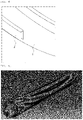
- FIG. 1 is a perspective view illustrating a portion of a spiral tube according to an embodiment of the present disclosure
- FIG. 2 is a partially enlarged view of the spiral tube illustrated in FIG. 1 .
- the spiral tube includes a tube body 1 in which a strip is connected in a spiral shape and joined at a front end thereof, and a stiffener 2 installed on an inner surface of the tube body.
- the tube body 1 is made of, for example, a hot-rolled coil made of a steel material and is welded in a spiral shape at an angle set according to a desired diameter while stretching and twisting a strip having a certain width.
- the strip When the strip is metal such as a steel material, the strip may have, for example, yield strength of about 400 MPa and tensile strength of about 440 MPa.
- the spiral tube according to an embodiment of the present disclosure does not require a smooth surface on the inside or outside of the tube since the purpose is not to transport a fluid.
- the stiffener 2 is joined to the inner surface of the tube body 1 and may be installed to protrude radially inwardly of the tube body.
- FIGS. 1 and 2 illustrate, for example, a stiffener 2 in a form of a flat plate having a radial length (that is, a width of the stiffener) of about 100 mm and a thickness of about 8 mm.
- the dimensions of the stiffener are not necessarily limited thereto, and the width and thickness of the stiffener may be changed according to the diameter of the spiral tube.
- the stiffener 2 may be positioned on the welding line 3 when welding while twisting, for example, a strip of hot-rolled coil by a continuous process to form the tube body 1, thereby being coupled to the inside of the tube body in a spiral shape without an additional welding process.
- stiffener 2 may be located away from the welding line, or may be joined to be slightly inclined with respect to the inner surface of the tube body 1.
- FIG. 3 is a perspective view illustrating a portion of a modified example of a spiral tube according to an embodiment of the present disclosure
- FIG. 4 is a partially enlarged view of the spiral tube illustrated in FIG. 2 .
- a stiffener 2 having a cross-sectional shape such as a bent approximately ⁇ shape, a U shape or a curved C shape is employed, so that an effect of reinforcing rigidity of the spiral tube can be further increased.
- the spiral tube according to an embodiment of the present disclosure adopts the stiffener 2 coupled to the inner surface thereof, so that it is possible to safely secure the resistance performance of the spiral tube against the collapse load caused by a pressure difference between an internal pressure, which is almost a vacuum, and an external pressure, which is atmospheric pressure.
- the thickness of the tube body 1 can be reduced to 25 mm or less while securing the same performance due to the stiffener 2.
- the tube body 1 when the tube body 1 has a diameter of 4 m, which is a large diameter, and has ovality of about 5.0%, a long axis diameter of the tube body increases by about 100 mm compared to a nominal diameter of 4 m. As a minor axis diameter is reduced by about 100 mm, the tube body may have an elliptical cross-sectional shape.
- the eliptical phenomenon may appear when forming the tube body 1, and may be further deteriorated by an external load during transport or construction of the tube body.
- the spiral tube may employ the stiffener 2 coupled to an inner surface thereof when the tube body 1 is formed, thereby safely securing the resistance performance against the collapse load by minimizing the elliptical phenomenon.
- FIGS. 5A and 5B are views illustrating collapse analysis of the spiral tube according to the prior art and the present disclosure.
- FIG. 5A illustrates a shape of numerical analysis of a collapse of a spiral tube according to the prior art, the spiral tube of the prior art having a diameter of 4 m, a thickness of 25 mm, and ovality of 5% applied thereto.
- a maximum resistive pressure was 0.17 MPa by applying a steel material having yield strength of 400 MPa and tensile strength of 440 MPa.
- the spiral tube according to the prior art cannot resist atmospheric pressure when an inside thereof is almost in a vacuum state and collapses.
- the diameter is 4 m, a tube having a thickness of 25 mm cannot be used, and the thickness of the tube must be further increased.
- FIG. 5B illustrates a shape of numerical analysis for a collapse of a spiral tube according to the present disclosure, and the spiral tube of the present disclosure having a diameter of 4 m and a thickness of 25 mm, and ovality of 5% applied thereto.
- a maximum resistance pressure was shown to 0.30 MPa by a stiffener 2 coupled to an inner surface thereof, and when an inside thereof is vacuum even considering a safety factor of 2.0, it can be seen that it resists an external atmospheric pressure, which is 1 atm.
- the present disclosure is useful for configuring a passage through which a travelling body moves in a high-speed train system or a hyperloop concept.
Landscapes
- Engineering & Computer Science (AREA)
- General Engineering & Computer Science (AREA)
- Mechanical Engineering (AREA)
- Rigid Pipes And Flexible Pipes (AREA)
- Lining And Supports For Tunnels (AREA)
Abstract
Description
- The present invention relates to a spiral tube capable of improving resistance performance against a collapse load generated by a difference between an internal pressure and an external pressure.
- For example, in a high-speed train system, of 300 km/h or more, two resistances must be solved depending on the speed. One is to design an aerodynamic travelling body to reduce air resistance rising exponentially, and the other is to introduce a magnetic levitation system to reduce frictional resistance between the travelling body and a track.
- Meanwhile, in a Hyperloop Concept, raised by Elon Musk in 2012 and first introduced by the technical staff of Tesla and SpaceX, a technology that can transport passengers at a maximum speed of 1200 km/h without air resistance by inserting a small travelling body (usually 28 seats) into a vacuum tube sealed at a pressure of approximately 0.001 atm, is proposed. Thereafter, various attempts have been made to actually implement such a system.
- In this attempt, while the electromagnetic and mechanical levitation and propulsion systems are important, it is also important to implement a tube structure to maintain a sub-vacuum state of approximately 0.001 atmosphere in infrastructure, accounting for about 50% or more of an initial investment value.
- Since the tube is set to be larger than a cross-sectional area of the travelling body since the tube is a passage through which a travelling body a passenger or a cargo moves, in general, a blockage ratio expressed by a cross-sectional area of the travelling body to a blockage ratio of the tube is 0.38 to 0.60.
- For example, in the hyperloop concept proposed in 2012, it was shown that when a diameter of the travelling body is 1.38m a blockage ratio is 0.38, but when the diameter of the travelling body is 1.38m, a height at which a person cannot stand up, there may be disadvantages to the passenger's boarding ability. Recently, in approaches such as Virgin Hyperloop One, the diameter of the travelling body is 2.4 m and the diameter of the tube is 3.66 m, which has a trend of enlargement.
- There are several mechanical performance requirements for the tube. One thereof is that an outgassing rate must be low to maintain a sub-vacuum of approximately 0.001 atm. For example, the steel material has excellent characteristics such as yield strength and tensile strength, but at about 0.001 atm, the outgassing rate is excellent compared to concrete or polymer composite materials, which are other candidate materials for the tube, so a tube made of steel material is considered first.
- As the diameter of the tube increases, a thickness of the tube also increases. For example, according to a pipeline design standard (DNV-OS-F101 standard), for example, when the diameter increases to 4 m, a safety thickness securing the resistance to collapse load along with a safety factor increases to 28.4 mm. Here, if the thickness of the steel is thicker than 25mm, there is a significant restriction on a production method of the tube.
- Specifically, a production equipment is set so that the hot-rolled coil of steel has a thickness of 25 mm or less, and steel products having a thickness of 25 mm or more usually have to be manufactured as a thick plate. When manufacturing a tube, a production cost of thick plate products is much higher than that of the continuous process of hot-rolled coils using a method that a continuous process cannot be performed. Therefore, it is necessary to make the thickness of the tube 25 mm or less to enable a continuous process in the manufacture of the tube and to reduce the initial investment cost.
- As related prior art, there is an invention disclosed in Republic of
Korea Patent Publication No. 1731869 B1 (noticed on May 4, 2017 - An aspect of the present disclosure is to provide a spiral tube capable of improving resistance performance against a collapse load generated by a difference between an internal pressure and an external pressure, while having a reduced thickness.
- According to an aspect of the present disclosure, a spiral tube includes: a tube body in which a strip is connected in a spiral shape and welded at a front end thereof; and a stiffener provided on an inner surface of the tube body.
- As described above, according to the present disclosure, by locating the stiffener in the tube body, resistance performance against a collapse load may be improved, while reducing the thickness of the tube.
-
-
FIG. 1 is a perspective view illustrating a portion of a spiral tube according to an embodiment of the present disclosure. -
FIG. 2 is a partially enlarged view of the spiral tube illustrated inFIG. 1 . -
FIG. 3 is a perspective view illustrating a portion of modified examples of a spiral tube according to an embodiment of the present disclosure. -
FIG. 4 is a partially enlarged view of the spiral tube shown inFIG. 2 . -
FIGS. 5A and5B are views illustrating collapse analysis of the spiral tube according to the prior art and the present disclosure. - Since a general pipeline transports pressure fluid, an internal pressure is greater than an external pressure, so an emphasis is on strengthening resistance to bursting rather than a collapse.
- For example, in manufacturing of a tube having a diameter of 1m or more, an economical spiral welding method is mainly used as a continuous process of hot-rolled coil.
- In the spiral tube produced in this manner, for example, when the diameter is 4 m and the thickness is 28.4 mm, a diameter-to-thickness ratio (D/t) is 130 or more, so that the spiral tube may have a diameter, which is relatively larger compared to a case of the general pipeline (for example, the diameter is 762 mm and the thickness is 20 mm, D/t = 38), and a very thin structure.
- As described above, when the diameter-to-thickness ratio (D/t) increases, it is very difficult to control ovality under the influence of its own weight.
- A control amount of the ovality of a general pipeline may be, for example, 0.5% or less in the case of a small diameter (diameter < 500 mm, D/t < 30), and in the case of a medium diameter (diameter < 1,300 mm, D/t < 45), the control amount thereof may be controlled to 1.5% or less.
- However, in the case of a large diameter of 4 m and a diameter-to-thickness ratio (D/t) of 130, the ovality is expected to be about 5.0%.
- In the case of pipelines transporting pressure fluids, a main reason for controlling this ovality is to match connection cross-sections between individual pipes.
- Meanwhile, when manufacturing a spiral tube, for example, a hot-rolled coil made of a steel material is stretched and twisted with a strip having a certain width, and welded in a spiral shape at an angle set according to a desired diameter.
- The conventional spiral tube is processed to maintain a smooth surface as much as possible, leaving only a weld bead on the inside and outside of the tube by butt welding according to a thickness of the strip. Such a smooth surface is especially for smooth movement of fluids (gas, oil, water, or the like) inside the spiral tube.
- On the other hand, the spiral tube according to the present disclosure is intended to be used as a tube in which the travelling body moves at a predetermined distance from the inner surface and has a vacuum thereinside. In the spiral tube, the resistance performance against the collapse load may be sufficiently secured.
- Hereinafter, the present disclosure will be described in detail with reference to exemplary drawings. In adding reference numerals to the components of each drawing, it should be noted that the same components are given the same reference numerals as much as possible even though they are indicated on different drawings.
- In addition, in describing the present disclosure, if it is determined that a detailed description of a related known configuration or function may obscure the gist of the present disclosure, the detailed description thereof will be omitted.
-
FIG. 1 is a perspective view illustrating a portion of a spiral tube according to an embodiment of the present disclosure, andFIG. 2 is a partially enlarged view of the spiral tube illustrated inFIG. 1 . - As illustrated in these drawings, the spiral tube according to an embodiment of the present disclosure includes a tube body 1 in which a strip is connected in a spiral shape and joined at a front end thereof, and a
stiffener 2 installed on an inner surface of the tube body. - The tube body 1 is made of, for example, a hot-rolled coil made of a steel material and is welded in a spiral shape at an angle set according to a desired diameter while stretching and twisting a strip having a certain width.
- When the strip is metal such as a steel material, the strip may have, for example, yield strength of about 400 MPa and tensile strength of about 440 MPa.
- Here, the spiral tube according to an embodiment of the present disclosure does not require a smooth surface on the inside or outside of the tube since the purpose is not to transport a fluid.
- The
stiffener 2 is joined to the inner surface of the tube body 1 and may be installed to protrude radially inwardly of the tube body. -
FIGS. 1 and2 illustrate, for example, astiffener 2 in a form of a flat plate having a radial length (that is, a width of the stiffener) of about 100 mm and a thickness of about 8 mm. - However, the dimensions of the stiffener are not necessarily limited thereto, and the width and thickness of the stiffener may be changed according to the diameter of the spiral tube.
- The
stiffener 2 may be positioned on thewelding line 3 when welding while twisting, for example, a strip of hot-rolled coil by a continuous process to form the tube body 1, thereby being coupled to the inside of the tube body in a spiral shape without an additional welding process. - Although the drawings illustrate an example in which the
stiffener 2 is positioned in an approximately orthogonal direction on thespiral welding line 3 on an inner side of the tube body 1, it is not necessarily limited thereto. - For example, the
stiffener 2 may be located away from the welding line, or may be joined to be slightly inclined with respect to the inner surface of the tube body 1. - In addition, although a continuous process of simultaneously welding the
stiffener 2 using thewelding wire 3 when forming the tube body 1 has been described above, a process of separately installing the stiffener after manufacturing the tube body may also be performed. -
FIG. 3 is a perspective view illustrating a portion of a modified example of a spiral tube according to an embodiment of the present disclosure, andFIG. 4 is a partially enlarged view of the spiral tube illustrated inFIG. 2 . - As shown in these figures, in a modified example of the spiral tube according to an embodiment of the present disclosure, a
stiffener 2 having a cross-sectional shape such as a bent approximately < shape, a U shape or a curved C shape is employed, so that an effect of reinforcing rigidity of the spiral tube can be further increased. - As described above, the spiral tube according to an embodiment of the present disclosure adopts the
stiffener 2 coupled to the inner surface thereof, so that it is possible to safely secure the resistance performance of the spiral tube against the collapse load caused by a pressure difference between an internal pressure, which is almost a vacuum, and an external pressure, which is atmospheric pressure. - In particular, when a diameter increases to 4m in a normal pipeline, a safety thickness securing the resistance performance against the collapse load along with the safety factor increases to 28.4mm, but in the spiral tube according to an embodiment of the present disclosure, the thickness of the tube body 1 can be reduced to 25 mm or less while securing the same performance due to the
stiffener 2. - Next, an important factor affecting the resistance performance of the spiral tube against the collapse load is ovality, which is a geometrical characteristic of the tube itself.
- For example, when the tube body 1 has a diameter of 4 m, which is a large diameter, and has ovality of about 5.0%, a long axis diameter of the tube body increases by about 100 mm compared to a nominal diameter of 4 m. As a minor axis diameter is reduced by about 100 mm, the tube body may have an elliptical cross-sectional shape.
- The eliptical phenomenon may appear when forming the tube body 1, and may be further deteriorated by an external load during transport or construction of the tube body.
- In the case of a spiral tube whose inside is maintained in an almost vacuum state, because of this elliptical phenomenon, when external atmospheric pressure acts as a load, collapse tends to occur in a direction of the minor axis diameter, so control of the elliptical phenomenon is required.
- As the elliptical phenomenon increases, the resistance performance against the collapse load decreases, so that the spiral tube according to an embodiment of the present disclosure may employ the
stiffener 2 coupled to an inner surface thereof when the tube body 1 is formed, thereby safely securing the resistance performance against the collapse load by minimizing the elliptical phenomenon. -
FIGS. 5A and5B are views illustrating collapse analysis of the spiral tube according to the prior art and the present disclosure. -
FIG. 5A illustrates a shape of numerical analysis of a collapse of a spiral tube according to the prior art, the spiral tube of the prior art having a diameter of 4 m, a thickness of 25 mm, and ovality of 5% applied thereto. - In addition, a maximum resistive pressure was 0.17 MPa by applying a steel material having yield strength of 400 MPa and tensile strength of 440 MPa.
- However, considering a safety factor of 2.0, it can be seen that the spiral tube according to the prior art cannot resist atmospheric pressure when an inside thereof is almost in a vacuum state and collapses. In other words, if the diameter is 4 m, a tube having a thickness of 25 mm cannot be used, and the thickness of the tube must be further increased.
-
FIG. 5B illustrates a shape of numerical analysis for a collapse of a spiral tube according to the present disclosure, and the spiral tube of the present disclosure having a diameter of 4 m and a thickness of 25 mm, and ovality of 5% applied thereto. - In addition, the same steel material as that of the spiral tube of the prior art was used.
- In the spiral tube according to the present disclosure, a maximum resistance pressure was shown to 0.30 MPa by a
stiffener 2 coupled to an inner surface thereof, and when an inside thereof is vacuum even considering a safety factor of 2.0, it can be seen that it resists an external atmospheric pressure, which is 1 atm. - As described above, according to the present disclosure, by locating the stiffener in the tube body, resistance performance against the collapse load may be provided, while reducing the thickness of the tube.
- Hereinafter, the present disclosure will be described in more detail through examples. However, it should be noted that the following examples are for illustrative purposes only and are not intended to limit the scope of the present disclosure. The scope of the present disclosure may be determined by matters described in the claims and matters able to be reasonably inferred therefrom. The subject of the present invention is not limited to the above. The subject of the present invention will be understood from the overall content of the present specification, and those of ordinary skill in the art to which the present invention pertains will have no difficulty in understanding the additional subject of the present invention.
- Accordingly, as described above, the present disclosure is useful for configuring a passage through which a travelling body moves in a high-speed train system or a hyperloop concept.
Claims (7)
- A spiral tube, comprising:a tube body in which a strip is connected in a spiral shape and welded at a front end thereof; anda stiffener provided on an inner surface of the tube body.
- The spiral tube of claim 1, wherein the strip is made of metal,the strip is welded, andthe stiffener is joined to an inner surface of the tube body and installed to protrude radially inwardly of the tube body.
- The spiral tube of claim 2, wherein the stiffener is coupled to an inside of the tube body in a spiral shape.
- The spiral tube of claim 3, wherein the stiffener is located at a welding line of the tube body.
- The spiral tube of claim 1, wherein the stiffener has a flat plate shape, and is joined in a direction, orthogonal to or obliquely to the inner surface of the tube body.
- The spiral tube of claim 1, wherein the stiffener has a cross-sectional shape of a bent or curved shape.
- The spiral tube of any one of claims 1 to 6, wherein a diameter of the tube body is 1m or more, and a thickness thereof exceeds 0 mm and is 25 mm or less.
Applications Claiming Priority (2)
| Application Number | Priority Date | Filing Date | Title |
|---|---|---|---|
| KR1020190164893A KR102305430B1 (en) | 2019-12-11 | 2019-12-11 | Spiral Tube |
| PCT/KR2020/001172 WO2021117977A1 (en) | 2019-12-11 | 2020-01-23 | Spiral tube |
Publications (4)
| Publication Number | Publication Date |
|---|---|
| EP4075039A1 true EP4075039A1 (en) | 2022-10-19 |
| EP4075039A4 EP4075039A4 (en) | 2023-04-05 |
| EP4075039C0 EP4075039C0 (en) | 2025-03-05 |
| EP4075039B1 EP4075039B1 (en) | 2025-03-05 |
Family
ID=76330430
Family Applications (1)
| Application Number | Title | Priority Date | Filing Date |
|---|---|---|---|
| EP20899067.1A Active EP4075039B1 (en) | 2019-12-11 | 2020-01-23 | Spiral tube |
Country Status (6)
| Country | Link |
|---|---|
| US (1) | US20230001464A1 (en) |
| EP (1) | EP4075039B1 (en) |
| JP (1) | JP7496874B2 (en) |
| KR (1) | KR102305430B1 (en) |
| CN (2) | CN121557351A (en) |
| WO (1) | WO2021117977A1 (en) |
Families Citing this family (1)
| Publication number | Priority date | Publication date | Assignee | Title |
|---|---|---|---|---|
| KR20240097193A (en) | 2022-12-20 | 2024-06-27 | 주식회사 포스코 | Tube for transportation system, transportation system and manufacturing method thereof |
Family Cites Families (27)
| Publication number | Priority date | Publication date | Assignee | Title |
|---|---|---|---|---|
| US308800A (en) * | 1884-12-02 | Sheet-metal pipe | ||
| US2067801A (en) * | 1935-09-28 | 1937-01-12 | Taylor Edward Hall | Metal strip for and method of making spiral pipe |
| JPS6195719A (en) * | 1984-10-15 | 1986-05-14 | Kawasaki Steel Corp | Steel pipe with spiral rib |
| JPS636289U (en) * | 1986-06-30 | 1988-01-16 | ||
| JP2756591B2 (en) * | 1989-08-25 | 1998-05-25 | 東京製綱株式会社 | Manufacturing method of metal tube with flocking |
| JPH08296767A (en) * | 1995-02-27 | 1996-11-12 | Sekisui Chem Co Ltd | Reinforcement material connection structure for spiral pipe |
| KR200274139Y1 (en) * | 1996-04-29 | 2002-09-04 | (주)신명건설기술공사 | Spiral tube reinforcement device |
| JP2003202149A (en) * | 2001-10-29 | 2003-07-18 | Kurimoto Ltd | Telescopic duct |
| US7004202B2 (en) * | 2002-04-22 | 2006-02-28 | Rib Loc Australia Pty Ltd. | Composite strip windable to form a helical pipe and method therefor |
| CN2627321Y (en) * | 2003-07-03 | 2004-07-21 | 蒯一希 | Plastic helical bellow |
| JP2005083422A (en) * | 2003-09-05 | 2005-03-31 | Kogen Kizai Kk | Protective tube and its manufacturing method |
| JP5447278B2 (en) * | 2009-08-17 | 2014-03-19 | 新日鐵住金株式会社 | Spiral steel pipe with internal protrusion and its manufacturing method |
| CN103192234B (en) * | 2013-04-01 | 2015-07-15 | 宝鸡石油钢管有限责任公司 | Spiral molded large-deformation-resistant submerged-arc welding pipe and manufacture method thereof |
| JP6161030B2 (en) * | 2013-07-29 | 2017-07-12 | 株式会社新富士空調 | Spiral tube manufacturing equipment |
| CN104266006B (en) * | 2014-09-18 | 2015-05-27 | 南京联众建设工程技术有限公司 | Spiral steel pipe with reinforcing ring and manufacturing method thereof |
| CN104295814B (en) * | 2014-10-14 | 2015-11-18 | 南京联众建设工程技术有限公司 | Underground steel and concrete structure pipeline of a kind of inner wall belt spiral compound stiffening ring and preparation method thereof |
| CN104565560B (en) * | 2014-12-24 | 2016-02-03 | 南京联众建设工程技术有限公司 | A kind of Large-sized spiral welded pipe with metal inner lining and preparation method thereof |
| CN105133646A (en) * | 2015-09-18 | 2015-12-09 | 南京联众建设工程技术有限公司 | Underground steel and concrete structure pipeline and manufacturing method thereof |
| CN105156771B (en) * | 2015-09-18 | 2016-09-28 | 南京联众建设工程技术有限公司 | Double metal spiral steel pipe and preparation method thereof |
| KR101731869B1 (en) | 2016-11-17 | 2017-05-04 | 주식회사천일공조 | A spiral seam pipe having an airtight member of a predetermined shape |
| GB201620745D0 (en) * | 2016-12-06 | 2017-01-18 | Ge Oil & Gas Uk Ltd | immobilised insert |
| KR101830638B1 (en) | 2016-12-12 | 2018-02-21 | 한국건설기술연구원 | Tube structure for integrating tube shield into concrete slab structure for super-speed tube railway, and construction for the same |
| WO2018129256A1 (en) * | 2017-01-06 | 2018-07-12 | Keystone Tower Systems, Inc. | Tube stiffening |
| JP6805041B2 (en) * | 2017-03-27 | 2020-12-23 | 積水化学工業株式会社 | Band-shaped member for spiral tube and spiral tube |
| KR101853915B1 (en) | 2017-11-21 | 2018-05-02 | 한국건설기술연구원 | Tabular structure of slab-canopy composite modular type for hyper-speed tube railway, and construction method for the same |
| WO2020038721A1 (en) | 2018-08-24 | 2020-02-27 | Tata Steel Nederland Technology B.V. | Tube segment for evacuated tube transport system |
| CN110026448B (en) * | 2019-04-30 | 2021-08-03 | 西安理工大学 | Integrally formed spiral stiffener steel pipe and forming method |
-
2019
- 2019-12-11 KR KR1020190164893A patent/KR102305430B1/en active Active
-
2020
- 2020-01-23 JP JP2022535236A patent/JP7496874B2/en active Active
- 2020-01-23 CN CN202511896208.0A patent/CN121557351A/en active Pending
- 2020-01-23 WO PCT/KR2020/001172 patent/WO2021117977A1/en not_active Ceased
- 2020-01-23 US US17/783,708 patent/US20230001464A1/en active Pending
- 2020-01-23 EP EP20899067.1A patent/EP4075039B1/en active Active
- 2020-01-23 CN CN202080085274.9A patent/CN114787548A/en active Pending
Also Published As
| Publication number | Publication date |
|---|---|
| KR102305430B1 (en) | 2021-09-27 |
| CN121557351A (en) | 2026-02-24 |
| JP7496874B2 (en) | 2024-06-12 |
| CN114787548A (en) | 2022-07-22 |
| EP4075039C0 (en) | 2025-03-05 |
| WO2021117977A1 (en) | 2021-06-17 |
| JP2023509326A (en) | 2023-03-08 |
| KR20210074006A (en) | 2021-06-21 |
| US20230001464A1 (en) | 2023-01-05 |
| EP4075039A4 (en) | 2023-04-05 |
| EP4075039B1 (en) | 2025-03-05 |
Similar Documents
| Publication | Publication Date | Title |
|---|---|---|
| JP4062862B2 (en) | Metal composite corrugated hose and manufacturing method thereof | |
| US10010983B2 (en) | Expandable member with wave inhibitor and methods of using the same | |
| JP4289686B2 (en) | Method for extending steel tubing and wells having such tubing | |
| EP4075039B1 (en) | Spiral tube | |
| JPS63299918A (en) | Manufacture of flexible pipe capable of receiving small curvature radius | |
| WO2016199643A1 (en) | Hydrogen-dispensing hose | |
| EP3858506A1 (en) | Long steel pipe for reel method and manufacturing method for same | |
| US20210163045A1 (en) | Evacuated tube transport system tube and use thereof | |
| CN111699300A (en) | Pipe section and pipe of vacuum pipe transport system | |
| GB2456225A (en) | A tubular article | |
| KR20240097193A (en) | Tube for transportation system, transportation system and manufacturing method thereof | |
| EP4334617A1 (en) | Conveying pipe part of a pneumatic material conveying system, conveying pipe arrangement and method for forming a conveying pipe arrangement | |
| US20190047595A1 (en) | Well car side assembly | |
| KR20250089930A (en) | Tube for transportation system and manufacturing method thereof | |
| JP7667374B2 (en) | Tube Structure | |
| WO2020043506A1 (en) | Method for producing a polyhedral helical tube and polyhedral helical tube produced thereby | |
| KR20260034574A (en) | Tube for transportation system | |
| CN220522622U (en) | Tunnel escape pipe | |
| US9578932B2 (en) | Variable radii flanges for mechanically retained crush tubes | |
| EP4596362A1 (en) | Tube for transportation system | |
| KR20260035090A (en) | Tube for transportation system | |
| EP4585488A1 (en) | Tube connecting structure and connection method thereof | |
| CN1986364B (en) | Level wound coil, method of manufacturing same, and package for same | |
| US20250340249A1 (en) | Structural member | |
| JP2000201586A (en) | Fishing rod |
Legal Events
| Date | Code | Title | Description |
|---|---|---|---|
| STAA | Information on the status of an ep patent application or granted ep patent |
Free format text: STATUS: THE INTERNATIONAL PUBLICATION HAS BEEN MADE |
|
| PUAI | Public reference made under article 153(3) epc to a published international application that has entered the european phase |
Free format text: ORIGINAL CODE: 0009012 |
|
| STAA | Information on the status of an ep patent application or granted ep patent |
Free format text: STATUS: REQUEST FOR EXAMINATION WAS MADE |
|
| 17P | Request for examination filed |
Effective date: 20220630 |
|
| AK | Designated contracting states |
Kind code of ref document: A1 Designated state(s): AL AT BE BG CH CY CZ DE DK EE ES FI FR GB GR HR HU IE IS IT LI LT LU LV MC MK MT NL NO PL PT RO RS SE SI SK SM TR |
|
| DAV | Request for validation of the european patent (deleted) | ||
| DAX | Request for extension of the european patent (deleted) | ||
| A4 | Supplementary search report drawn up and despatched |
Effective date: 20230306 |
|
| RIC1 | Information provided on ipc code assigned before grant |
Ipc: F16L 9/16 20060101ALI20230228BHEP Ipc: F16L 11/16 20060101AFI20230228BHEP |
|
| STAA | Information on the status of an ep patent application or granted ep patent |
Free format text: STATUS: EXAMINATION IS IN PROGRESS |
|
| 17Q | First examination report despatched |
Effective date: 20240130 |
|
| GRAP | Despatch of communication of intention to grant a patent |
Free format text: ORIGINAL CODE: EPIDOSNIGR1 |
|
| STAA | Information on the status of an ep patent application or granted ep patent |
Free format text: STATUS: GRANT OF PATENT IS INTENDED |
|
| INTG | Intention to grant announced |
Effective date: 20240916 |
|
| GRAS | Grant fee paid |
Free format text: ORIGINAL CODE: EPIDOSNIGR3 |
|
| GRAA | (expected) grant |
Free format text: ORIGINAL CODE: 0009210 |
|
| STAA | Information on the status of an ep patent application or granted ep patent |
Free format text: STATUS: THE PATENT HAS BEEN GRANTED |
|
| AK | Designated contracting states |
Kind code of ref document: B1 Designated state(s): AL AT BE BG CH CY CZ DE DK EE ES FI FR GB GR HR HU IE IS IT LI LT LU LV MC MK MT NL NO PL PT RO RS SE SI SK SM TR |
|
| REG | Reference to a national code |
Ref country code: GB Ref legal event code: FG4D |
|
| REG | Reference to a national code |
Ref country code: CH Ref legal event code: EP |
|
| REG | Reference to a national code |
Ref country code: IE Ref legal event code: FG4D |
|
| REG | Reference to a national code |
Ref country code: DE Ref legal event code: R096 Ref document number: 602020047428 Country of ref document: DE |
|
| U01 | Request for unitary effect filed |
Effective date: 20250321 |
|
| U07 | Unitary effect registered |
Designated state(s): AT BE BG DE DK EE FI FR IT LT LU LV MT NL PT RO SE SI Effective date: 20250327 |
|
| PG25 | Lapsed in a contracting state [announced via postgrant information from national office to epo] |
Ref country code: RS Free format text: LAPSE BECAUSE OF FAILURE TO SUBMIT A TRANSLATION OF THE DESCRIPTION OR TO PAY THE FEE WITHIN THE PRESCRIBED TIME-LIMIT Effective date: 20250605 |
|
| PG25 | Lapsed in a contracting state [announced via postgrant information from national office to epo] |
Ref country code: ES Free format text: LAPSE BECAUSE OF FAILURE TO SUBMIT A TRANSLATION OF THE DESCRIPTION OR TO PAY THE FEE WITHIN THE PRESCRIBED TIME-LIMIT Effective date: 20250305 |
|
| PG25 | Lapsed in a contracting state [announced via postgrant information from national office to epo] |
Ref country code: NO Free format text: LAPSE BECAUSE OF FAILURE TO SUBMIT A TRANSLATION OF THE DESCRIPTION OR TO PAY THE FEE WITHIN THE PRESCRIBED TIME-LIMIT Effective date: 20250605 |
|
| PG25 | Lapsed in a contracting state [announced via postgrant information from national office to epo] |
Ref country code: HR Free format text: LAPSE BECAUSE OF FAILURE TO SUBMIT A TRANSLATION OF THE DESCRIPTION OR TO PAY THE FEE WITHIN THE PRESCRIBED TIME-LIMIT Effective date: 20250305 |
|
| PG25 | Lapsed in a contracting state [announced via postgrant information from national office to epo] |
Ref country code: GR Free format text: LAPSE BECAUSE OF FAILURE TO SUBMIT A TRANSLATION OF THE DESCRIPTION OR TO PAY THE FEE WITHIN THE PRESCRIBED TIME-LIMIT Effective date: 20250606 |
|
| PG25 | Lapsed in a contracting state [announced via postgrant information from national office to epo] |
Ref country code: SM Free format text: LAPSE BECAUSE OF FAILURE TO SUBMIT A TRANSLATION OF THE DESCRIPTION OR TO PAY THE FEE WITHIN THE PRESCRIBED TIME-LIMIT Effective date: 20250305 |
|
| PG25 | Lapsed in a contracting state [announced via postgrant information from national office to epo] |
Ref country code: PL Free format text: LAPSE BECAUSE OF FAILURE TO SUBMIT A TRANSLATION OF THE DESCRIPTION OR TO PAY THE FEE WITHIN THE PRESCRIBED TIME-LIMIT Effective date: 20250305 |
|
| PG25 | Lapsed in a contracting state [announced via postgrant information from national office to epo] |
Ref country code: CZ Free format text: LAPSE BECAUSE OF FAILURE TO SUBMIT A TRANSLATION OF THE DESCRIPTION OR TO PAY THE FEE WITHIN THE PRESCRIBED TIME-LIMIT Effective date: 20250305 |
|
| PG25 | Lapsed in a contracting state [announced via postgrant information from national office to epo] |
Ref country code: SK Free format text: LAPSE BECAUSE OF FAILURE TO SUBMIT A TRANSLATION OF THE DESCRIPTION OR TO PAY THE FEE WITHIN THE PRESCRIBED TIME-LIMIT Effective date: 20250305 |
|
| PG25 | Lapsed in a contracting state [announced via postgrant information from national office to epo] |
Ref country code: IS Free format text: LAPSE BECAUSE OF FAILURE TO SUBMIT A TRANSLATION OF THE DESCRIPTION OR TO PAY THE FEE WITHIN THE PRESCRIBED TIME-LIMIT Effective date: 20250705 |
|
| PLBE | No opposition filed within time limit |
Free format text: ORIGINAL CODE: 0009261 |
|
| STAA | Information on the status of an ep patent application or granted ep patent |
Free format text: STATUS: NO OPPOSITION FILED WITHIN TIME LIMIT |
|
| REG | Reference to a national code |
Ref country code: CH Ref legal event code: L10 Free format text: ST27 STATUS EVENT CODE: U-0-0-L10-L00 (AS PROVIDED BY THE NATIONAL OFFICE) Effective date: 20260114 |
|
| 26N | No opposition filed |
Effective date: 20251208 |
|
| U20 | Renewal fee for the european patent with unitary effect paid |
Year of fee payment: 7 Effective date: 20260122 |