EP4074998A1 - Rolling guide device and opening and closing mechanism - Google Patents
Rolling guide device and opening and closing mechanism Download PDFInfo
- Publication number
- EP4074998A1 EP4074998A1 EP22167867.5A EP22167867A EP4074998A1 EP 4074998 A1 EP4074998 A1 EP 4074998A1 EP 22167867 A EP22167867 A EP 22167867A EP 4074998 A1 EP4074998 A1 EP 4074998A1
- Authority
- EP
- European Patent Office
- Prior art keywords
- rolling
- guide device
- rolling element
- contact
- pair
- Prior art date
- Legal status (The legal status is an assumption and is not a legal conclusion. Google has not performed a legal analysis and makes no representation as to the accuracy of the status listed.)
- Granted
Links
Images



Classifications
-
- F—MECHANICAL ENGINEERING; LIGHTING; HEATING; WEAPONS; BLASTING
- F16—ENGINEERING ELEMENTS AND UNITS; GENERAL MEASURES FOR PRODUCING AND MAINTAINING EFFECTIVE FUNCTIONING OF MACHINES OR INSTALLATIONS; THERMAL INSULATION IN GENERAL
- F16C—SHAFTS; FLEXIBLE SHAFTS; ELEMENTS OR CRANKSHAFT MECHANISMS; ROTARY BODIES OTHER THAN GEARING ELEMENTS; BEARINGS
- F16C29/00—Bearings for parts moving only linearly
- F16C29/04—Ball or roller bearings
-
- E—FIXED CONSTRUCTIONS
- E05—LOCKS; KEYS; WINDOW OR DOOR FITTINGS; SAFES
- E05D—HINGES OR SUSPENSION DEVICES FOR DOORS, WINDOWS OR WINGS
- E05D15/00—Suspension arrangements for wings
- E05D15/06—Suspension arrangements for wings for wings sliding horizontally more or less in their own plane
- E05D15/0621—Details, e.g. suspension or supporting guides
- E05D15/0626—Details, e.g. suspension or supporting guides for wings suspended at the top
- E05D15/0652—Tracks
-
- A—HUMAN NECESSITIES
- A47—FURNITURE; DOMESTIC ARTICLES OR APPLIANCES; COFFEE MILLS; SPICE MILLS; SUCTION CLEANERS IN GENERAL
- A47B—TABLES; DESKS; OFFICE FURNITURE; CABINETS; DRAWERS; GENERAL DETAILS OF FURNITURE
- A47B88/00—Drawers for tables, cabinets or like furniture; Guides for drawers
- A47B88/40—Sliding drawers; Slides or guides therefor
- A47B88/483—Sliding drawers; Slides or guides therefor with single extensible guides or parts
- A47B88/487—Sliding drawers; Slides or guides therefor with single extensible guides or parts with rollers, ball bearings, wheels, or the like
-
- A—HUMAN NECESSITIES
- A47—FURNITURE; DOMESTIC ARTICLES OR APPLIANCES; COFFEE MILLS; SPICE MILLS; SUCTION CLEANERS IN GENERAL
- A47B—TABLES; DESKS; OFFICE FURNITURE; CABINETS; DRAWERS; GENERAL DETAILS OF FURNITURE
- A47B88/00—Drawers for tables, cabinets or like furniture; Guides for drawers
- A47B88/40—Sliding drawers; Slides or guides therefor
- A47B88/49—Sliding drawers; Slides or guides therefor with double extensible guides or parts
- A47B88/493—Sliding drawers; Slides or guides therefor with double extensible guides or parts with rollers, ball bearings, wheels, or the like
-
- B—PERFORMING OPERATIONS; TRANSPORTING
- B61—RAILWAYS
- B61D—BODY DETAILS OR KINDS OF RAILWAY VEHICLES
- B61D19/00—Door arrangements specially adapted for rail vehicles
- B61D19/003—Door arrangements specially adapted for rail vehicles characterised by the movements of the door
- B61D19/005—Door arrangements specially adapted for rail vehicles characterised by the movements of the door sliding
-
- E—FIXED CONSTRUCTIONS
- E05—LOCKS; KEYS; WINDOW OR DOOR FITTINGS; SAFES
- E05D—HINGES OR SUSPENSION DEVICES FOR DOORS, WINDOWS OR WINGS
- E05D13/00—Accessories for sliding or lifting wings, e.g. pulleys, safety catches
-
- E—FIXED CONSTRUCTIONS
- E05—LOCKS; KEYS; WINDOW OR DOOR FITTINGS; SAFES
- E05D—HINGES OR SUSPENSION DEVICES FOR DOORS, WINDOWS OR WINGS
- E05D15/00—Suspension arrangements for wings
- E05D15/06—Suspension arrangements for wings for wings sliding horizontally more or less in their own plane
- E05D15/0621—Details, e.g. suspension or supporting guides
- E05D15/0626—Details, e.g. suspension or supporting guides for wings suspended at the top
- E05D15/063—Details, e.g. suspension or supporting guides for wings suspended at the top on wheels with fixed axis
-
- E—FIXED CONSTRUCTIONS
- E05—LOCKS; KEYS; WINDOW OR DOOR FITTINGS; SAFES
- E05D—HINGES OR SUSPENSION DEVICES FOR DOORS, WINDOWS OR WINGS
- E05D15/00—Suspension arrangements for wings
- E05D15/06—Suspension arrangements for wings for wings sliding horizontally more or less in their own plane
- E05D15/0621—Details, e.g. suspension or supporting guides
- E05D15/0626—Details, e.g. suspension or supporting guides for wings suspended at the top
- E05D15/0647—Details, e.g. suspension or supporting guides for wings suspended at the top on sliding blocks
-
- E—FIXED CONSTRUCTIONS
- E06—DOORS, WINDOWS, SHUTTERS, OR ROLLER BLINDS IN GENERAL; LADDERS
- E06B—FIXED OR MOVABLE CLOSURES FOR OPENINGS IN BUILDINGS, VEHICLES, FENCES OR LIKE ENCLOSURES IN GENERAL, e.g. DOORS, WINDOWS, BLINDS, GATES
- E06B3/00—Window sashes, door leaves, or like elements for closing wall or like openings; Layout of fixed or moving closures, e.g. windows in wall or like openings; Features of rigidly-mounted outer frames relating to the mounting of wing frames
- E06B3/32—Arrangements of wings characterised by the manner of movement; Arrangements of movable wings in openings; Features of wings or frames relating solely to the manner of movement of the wing
- E06B3/34—Arrangements of wings characterised by the manner of movement; Arrangements of movable wings in openings; Features of wings or frames relating solely to the manner of movement of the wing with only one kind of movement
- E06B3/42—Sliding wings; Details of frames with respect to guiding
- E06B3/46—Horizontally-sliding wings
- E06B3/4636—Horizontally-sliding wings for doors
-
- F—MECHANICAL ENGINEERING; LIGHTING; HEATING; WEAPONS; BLASTING
- F16—ENGINEERING ELEMENTS AND UNITS; GENERAL MEASURES FOR PRODUCING AND MAINTAINING EFFECTIVE FUNCTIONING OF MACHINES OR INSTALLATIONS; THERMAL INSULATION IN GENERAL
- F16C—SHAFTS; FLEXIBLE SHAFTS; ELEMENTS OR CRANKSHAFT MECHANISMS; ROTARY BODIES OTHER THAN GEARING ELEMENTS; BEARINGS
- F16C29/00—Bearings for parts moving only linearly
- F16C29/005—Guide rails or tracks for a linear bearing, i.e. adapted for movement of a carriage or bearing body there along
-
- F—MECHANICAL ENGINEERING; LIGHTING; HEATING; WEAPONS; BLASTING
- F16—ENGINEERING ELEMENTS AND UNITS; GENERAL MEASURES FOR PRODUCING AND MAINTAINING EFFECTIVE FUNCTIONING OF MACHINES OR INSTALLATIONS; THERMAL INSULATION IN GENERAL
- F16C—SHAFTS; FLEXIBLE SHAFTS; ELEMENTS OR CRANKSHAFT MECHANISMS; ROTARY BODIES OTHER THAN GEARING ELEMENTS; BEARINGS
- F16C33/00—Parts of bearings; Special methods for making bearings or parts thereof
- F16C33/30—Parts of ball or roller bearings
- F16C33/58—Raceways; Race rings
- F16C33/583—Details of specific parts of races
- F16C33/585—Details of specific parts of races of raceways, e.g. ribs to guide the rollers
-
- E—FIXED CONSTRUCTIONS
- E05—LOCKS; KEYS; WINDOW OR DOOR FITTINGS; SAFES
- E05Y—INDEXING SCHEME ASSOCIATED WITH SUBCLASSES E05D AND E05F, RELATING TO CONSTRUCTION ELEMENTS, ELECTRIC CONTROL, POWER SUPPLY, POWER SIGNAL OR TRANSMISSION, USER INTERFACES, MOUNTING OR COUPLING, DETAILS, ACCESSORIES, AUXILIARY OPERATIONS NOT OTHERWISE PROVIDED FOR, APPLICATION THEREOF
- E05Y2900/00—Application of doors, windows, wings or fittings thereof
- E05Y2900/10—Application of doors, windows, wings or fittings thereof for buildings or parts thereof
- E05Y2900/13—Type of wing
- E05Y2900/132—Doors
-
- F—MECHANICAL ENGINEERING; LIGHTING; HEATING; WEAPONS; BLASTING
- F16—ENGINEERING ELEMENTS AND UNITS; GENERAL MEASURES FOR PRODUCING AND MAINTAINING EFFECTIVE FUNCTIONING OF MACHINES OR INSTALLATIONS; THERMAL INSULATION IN GENERAL
- F16C—SHAFTS; FLEXIBLE SHAFTS; ELEMENTS OR CRANKSHAFT MECHANISMS; ROTARY BODIES OTHER THAN GEARING ELEMENTS; BEARINGS
- F16C2220/00—Shaping
- F16C2220/60—Shaping by removing material, e.g. machining
- F16C2220/70—Shaping by removing material, e.g. machining by grinding
-
- F—MECHANICAL ENGINEERING; LIGHTING; HEATING; WEAPONS; BLASTING
- F16—ENGINEERING ELEMENTS AND UNITS; GENERAL MEASURES FOR PRODUCING AND MAINTAINING EFFECTIVE FUNCTIONING OF MACHINES OR INSTALLATIONS; THERMAL INSULATION IN GENERAL
- F16C—SHAFTS; FLEXIBLE SHAFTS; ELEMENTS OR CRANKSHAFT MECHANISMS; ROTARY BODIES OTHER THAN GEARING ELEMENTS; BEARINGS
- F16C2300/00—Application independent of particular apparatuses
- F16C2300/20—Application independent of particular apparatuses related to type of movement
- F16C2300/28—Reciprocating movement
-
- F—MECHANICAL ENGINEERING; LIGHTING; HEATING; WEAPONS; BLASTING
- F16—ENGINEERING ELEMENTS AND UNITS; GENERAL MEASURES FOR PRODUCING AND MAINTAINING EFFECTIVE FUNCTIONING OF MACHINES OR INSTALLATIONS; THERMAL INSULATION IN GENERAL
- F16C—SHAFTS; FLEXIBLE SHAFTS; ELEMENTS OR CRANKSHAFT MECHANISMS; ROTARY BODIES OTHER THAN GEARING ELEMENTS; BEARINGS
- F16C2314/00—Personal or domestic articles, e.g. household appliances such as washing machines, dryers
- F16C2314/70—Furniture
- F16C2314/72—Drawers
-
- F—MECHANICAL ENGINEERING; LIGHTING; HEATING; WEAPONS; BLASTING
- F16—ENGINEERING ELEMENTS AND UNITS; GENERAL MEASURES FOR PRODUCING AND MAINTAINING EFFECTIVE FUNCTIONING OF MACHINES OR INSTALLATIONS; THERMAL INSULATION IN GENERAL
- F16C—SHAFTS; FLEXIBLE SHAFTS; ELEMENTS OR CRANKSHAFT MECHANISMS; ROTARY BODIES OTHER THAN GEARING ELEMENTS; BEARINGS
- F16C29/00—Bearings for parts moving only linearly
- F16C29/001—Bearings for parts moving only linearly adjustable for alignment or positioning
-
- F—MECHANICAL ENGINEERING; LIGHTING; HEATING; WEAPONS; BLASTING
- F16—ENGINEERING ELEMENTS AND UNITS; GENERAL MEASURES FOR PRODUCING AND MAINTAINING EFFECTIVE FUNCTIONING OF MACHINES OR INSTALLATIONS; THERMAL INSULATION IN GENERAL
- F16C—SHAFTS; FLEXIBLE SHAFTS; ELEMENTS OR CRANKSHAFT MECHANISMS; ROTARY BODIES OTHER THAN GEARING ELEMENTS; BEARINGS
- F16C29/00—Bearings for parts moving only linearly
- F16C29/04—Ball or roller bearings
- F16C29/045—Ball or roller bearings having rolling elements journaled in one of the moving parts
Definitions
- the present invention relates to a rolling guide device and an opening and closing mechanism using the rolling guide device.
- a rolling guide device including a track rail extending in a longitudinal direction and having a substantial C-shape in cross-section, a slider installed in such a manner as to be capable of reciprocating movement along the longitudinal direction of the track rail, and a plurality of rolling elements rollably disposed in an inner space of the substantial C-shape of the track rail between the track rail and the slider to guide reciprocating movement of the slider relative to the track rail has been publicly known.
- linear bearing disclosed in Japanese Patent No. 3292459 .
- This linear bearing has a configuration in which two, right and left, linear rails each having a C-shape in cross-section are provided in parallel in such a manner as to face each other in a right-left direction, two inner tracks are formed in each of the rails in such a manner as to face each other in an up-down direction, a slider including three or more rollers that are in contact with upper and lower inner tracks alternately is provided, an outline of an outer circumferential surface of each roller has a shape of a circular arc with a radius r in cross-section, one of the upper and lower inner tracks has a V-shape in cross-section and the other inner track has a shape of a circular arc with a radius R in cross-section and the radius R is longer than the radius r of the outline of the roller. Because of such configuration, the linear bearing disclosed in Japanese Patent No. 3292459 is described as enabling the
- conventional rolling guide devices represented by the linear bearing disclosed in the aforementioned Japanese Patent No. 3292459 may fail to perform a proper and stable guiding operation if a roll moment Mc is applied to a moving member such as a slider.
- a roll moment Mc is applied to a moving member such as a slider.
- the hanging door exerts unbalanced weight on the moving member. If such unbalanced weight is applied to the moving member, the conventional rolling guide device fails to perform a proper and stable guiding operation because of poor rigidity against a roll moment Mc.
- the present invention has been made in view of the above case in the conventional techniques, and an object of the present invention is to provide a rolling guide device capable of performing a proper and stable guiding operation even if unbalanced weight is applied to a moving member, through enhancement in rigidity against a roll moment Mc.
- a rolling guide device is a rolling guide device including: a track member that is a long member extending in a longitudinal direction, the track member including a mounting surface portion that serves as a base for mounting to an external member and a pair of wall portions provided in such a manner as to stand from respective opposite end portions of the mounting surface portion toward one side; a moving member installed in such a manner as to be capable of reciprocating movement along the longitudinal direction of the track member; and a plurality of first rolling elements rollably disposed inside a space between the track member and the moving member, the space being surrounded by the mounting surface portion and the pair of wall portions included in the track member, to guide reciprocating movement of the moving member relative to the track member, wherein a rolling element rolling surface that is in contact with a rolling element outer circumferential surface of a first rolling element from among the first rolling elements is formed at each of respective wall surfaces of the pair of wall portions, the wall surfaces facing each other, the rolling element rolling surfaces formed at the pair of wall portions, respectively, are each formed as a circular
- the present invention includes an opening and closing mechanism including the above rolling guide device, the track member of the rolling guide device being installed on a door frame, a door body being installed on the moving member, to allow the opening and closing mechanism to perform an operation of opening and closing the door body relative to the door frame.
- the present invention enables provision of a rolling guide device capable of performing a proper and stable guiding operation even if unbalanced weight is applied to a moving member, through enhancement in rigidity against a roll moment Mc.
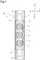
- Fig. 1 is a transparent view of a rolling guide device according to a first embodiment from the front side
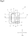
- Fig. 2 is a transparent view of the rolling guide device according to the first embodiment from the left side.
- directions in the rolling guide device 10 are defined as illustrated in Figs. 1 and 2 .
- these directions are not those indicating directions when the rolling guide device 10 according to the first embodiment is in use, and the rolling guide device 10 according to the first embodiment can be used in any position.
- the directions "front”, “rear”, “up”, “down”, “right” and “left” indicated in Figs. 1 and 2 are definitely those determined for convenience of description.
- the rolling guide device 10 includes a track rail 11, which serves as a track member, a moving slider 21, which serves as a moving member installed in such a manner as to be capable of reciprocating movement along a longitudinal direction of the track rail 11 (that is, the right-left direction in Fig. 1 ), first wheels 31, which each serve as a first rolling element rollably disposed between the track rail 11 and the moving slider 21, and second rollers 41, which each serve as a second rolling element rollably disposed on the lower surface side of the moving slider 21.
- the track rail 11 is a long member extending in the longitudinal direction and having a substantial C-shape in cross-section.
- the track rail 11 of the first embodiment includes a mounting surface portion 12 extending in the up-down direction, an upper wall portion 13, which serves as a wall portion according to the present invention, the upper wall portion 13 extending frontward from an upper end of the mounting surface portion 12, and a lower wall portion 14, which serves as a wall portion according to the present invention, the lower wall portion 14 extending frontward from a lower end of the mounting surface portion 12, in side view.
- a first wheel upper rolling surface 13a which serves as a rolling element rolling surface according to the present invention, the first wheel upper rolling surface 13a being in contact with a wheel outer circumferential surface of a relevant first wheel 31, is formed.
- a first wheel lower rolling surface 14a which serves as a rolling element rolling surface according to the present invention, the first wheel lower rolling surface 14a being in contact with a wheel outer circumferential surface of each of relevant first wheels 31, is formed.
- the first wheel upper rolling surface 13a and the first wheel lower rolling surface 14a are disposed in such a manner as to face each other in side view. Then, the first wheels 31 are rollably disposed in an inner space 15 surrounded by the mounting surface portion 12, the upper wall portion 13 and the lower wall portion 14 (inside a space according to the present invention).
- the track rail 11 of the first embodiment is formed in the aforementioned contour shape by plastically deforming a metal material via a drawing process and forming a part of the track rail 11 that the later-described second rollers 41 come into contact with, that is, a part of a lower open end portion 14b of the substantial C-shape of the track rail 11 (outer end portion according to the present invention), as a flat surface subjected to a grinding process.
- a method for forming the track rail 11 is not limited to a combination of a drawing process and a grinding process.
- the outer appearance shape may be formed by performing, e.g., a grinding process or a cutting process of a metal material or the contour shape may be formed by plastically deforming a metal material via a drawing process and subsequently performing a thermal treatment process to control a surface hardness and internal quality and then performing, e.g., a grinding process.
- the contour shape of the track rail 11, which is a track member of the present invention can be formed using any process method.
- the track rail 11 of the first embodiment is a member that serves as a base for mounting of the rolling guide device 10. Therefore, in the first embodiment, mounting holes 12a such as bolt holes are formed in the mounting surface portion 12 included in the track rail 11, enabling the track rail 11 to be fixedly installed on a mounting base surface of, e.g., a base or a door frame using the mounting holes 12a.
- the moving slider 21 is a block-like member having a substantially rectangular shape and is disposed in such a manner as to be capable of reciprocating movement along the longitudinal direction of the track rail 11.
- three first wheels 31 are rollably disposed on the rear surface side and two second rollers 41 are rollably disposed on the lower surface side.
- a movable member to be guided and moved by the rolling guide device 10 can be installed on the front surface side of the moving slider 21.
- Each of the first wheels 31 is a member rollably disposed in the inner space 15 of the substantial C-shape of the track rail 11, between the track rail 11 and the moving slider 21, to guide reciprocating movement of the moving slider 21 relative to the track rail 11.
- first wheels 31 of the first embodiment three first wheels 31 are rollably disposed on the rear surface side of the moving slider 21. Then, as is clear with reference to the comparison between Figs. 1 and 2 , one first wheel 31 located at a center from among the three first wheels 31 is disposed in such a manner as to be in contact with the first wheel upper rolling surface 13a and be not in contact with, but be spaced from, the first wheel lower rolling surface 14a. On the other hand, two first wheels 31 located at the right and the left from among the three first wheels 31 are disposed in such a manner as to be in contact with the first wheel lower rolling surface 14a and be not in contact with, but be spaced from, the first wheel upper rolling surface 13a.
- the three first wheels 31 are disposed in such a manner as to be staggered in the up-down direction in front view in this way, for example, when the moving slider 21 moves to the right side of the sheet relative to the track rail 11 in Fig. 1 , the one first wheel 31 located at the center rotates counterclockwise in the sheet of Fig. 1 and the two first wheels 31 located at the right and the left rotate clockwise in the sheet of Fig. 1 . Also, conversely, when the moving slider 21 moves to the left side of the sheet relative to the track rail 11 in Fig. 1 , the one first wheel 31 located at the center rotates clockwise in the sheet of Fig. 1 and the two first wheels 31 located at the right and the left rotate counterclockwise in the sheet of Fig.
- the three first wheels 31 being disposed in such a manner as to be staggered in the up-down direction in front view enables the moving slider 21 that makes relative linear movement along the longitudinal direction of the track rail 11 to make favorable linear reciprocating movement while properly receiving a moment load.
- the one first wheel 31 located at the center is disposed in contact with the first wheel upper rolling surface 13a and the two first wheels 31 located at the right and the left are disposed in contact with the first wheel lower rolling surface 14a.
- the scope of the present invention is not limited to this example, and for example, a configuration in which the one first wheel 31 located at the center is disposed in contact with the first wheel lower rolling surface 14a and the two first wheels 31 located at the right and the left are disposed in contact with the first wheel upper rolling surface 13a, which is a disposition opposite to the first embodiment, may be employed.
- first wheels 31 are disposed on the rear surface side of the moving slider 21; however, in the case of this example configuration, it is preferable that adjacent first wheels 31 be disposed in contact with the first wheel upper rolling surface 13a and the first wheel lower rolling surface 14a alternately.
- wheel in the present invention refers to a wheel member rotatably mounted on a rotation shaft, and may be one including a rolling contact surface of contact with a counterpart member, the rolling contact surface including any of a horizontal surface, a projecting curve surface and a recessed curve surface.
- the rolling contact surface of the first wheel 31 is formed as a projecting curve surface is illustrated as an example (see Fig. 2 ).
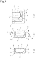
- Fig. 3 includes schematic diagrams for describing a manner of a first wheel rolling on a first wheel upper rolling surface and a first wheel lower rolling surface in the first embodiment.
- Fig. 3(a) illustrates a state in which no roll moment Mc is applied to the moving slider 21
- Fig. 3(b) illustrates a state in which a roll moment Mc is applied to the moving slider 21
- Fig. 3(c) is an enlarged view of a dashed line region indicated by sign ⁇ in Fig. 3(b) .
- the first wheel upper rolling surface 13a and the first wheel lower rolling surface 14a each have a shape of a circular arc groove formed of a single circular arc in cross-section.
- a radius of curvature of each of the first wheel upper rolling surface 13a and the first wheel lower rolling surface 14a is slightly larger than a radius of curvature of the rolling contact surface of each first wheel 31. Therefore, each first wheel 31 according to the first embodiment comes into contact with the first wheel upper rolling surface 13a and the first wheel lower rolling surface 14a at one point.
- a line L 1 indicating a roll direction orthogonal to a rotation center line of the first wheel 31 is a vertical line extending in the up-down direction, and respective contact points P 1 of contact between the first wheels 31 and the first wheel upper rolling surface 13a and the first wheel lower rolling surface 14a are located at respective centers of groove bottoms of the circular arc grooves forming the first wheel upper rolling surface 13a and the first wheel lower rolling surface 14a.
- the first wheels 31 are inclined in the direction in which the moment Mc is applied (clockwise direction in the sheet of Fig. 3(b) ).
- the line L 1 indicating the roll direction orthogonal to the rotation center line of the first wheel 31 is inclined to the position of a line L 2 .
- the contact points move from the contact points P 1 to contact points P 2 according to the clockwise inclination of the first wheels 31.
- the contact points shift according to the moment Mc and each of the first wheels 31 and the first wheel upper rolling surface 13a and the first wheel lower rolling surface 14a are consistently in contact with each other at one point, enabling a favorable rolling motion with a smaller differential slippage amount to be consistently provided.
- a rotation center line 31a of each of the first wheels 31 described above is a horizontal line along the front-rear direction.
- a rotation center line 41a of each of the second rollers 41 disposed on the lower surface side of the moving slider 21 is a vertical line extending along the up-down direction.
- each second roller 41 according to the first embodiment has a rotation center axis 41a in a direction substantially orthogonal to the rotation center axes 31a of the first wheels 31.
- each second roller 41 is configured to roll in contact with the lower open end portion 14b of the substantial C-shape of the track rail 11.
- the first wheel upper rolling surface 13a and the first wheel lower rolling surface 14a that are in contact with the first wheels 31 are each configured as a circular arc groove, and thus, application of an external load to the moving slider 21 causes the contact points P 1 , P 2 to consistently shift.
- the second rollers 41 are each configured to roll in contact with the lower open end portion 14b of the substantial C-shape of the track rail 11, and thus properly compensate for the shifting of the contact points P 1 , P 2 , enabling the first wheels 31 and the second rollers 41 to cooperatively receive a roll moment Mc.
- a combination of two configurations, the configuration of the first wheels 31 and the first wheel upper rolling surface 13a and the first wheel lower rolling surface 14a and the configuration of the second rollers 41 and the lower open end portion 14b of the substantial C-shape of the track rail 11, enables enhancement in rigidity against a roll moment Mc, and thus enables provision of the rolling guide device 10 capable of performing a proper and stable guiding operation even if unbalanced weight is applied to the moving slider 21.
- the first wheel upper rolling surface 13a and the first wheel lower rolling surface 14a that are in contact with the first wheels 31 are each configured as a circular arc groove, and thus, a merit of mounting error absorption shows up as a displacement depending on the counterpart of the mounting. Therefore, in particular, in the case of the first embodiment in which circular arc grooves are employed for the first wheel upper rolling surface 13a and the first wheel lower rolling surface 14a that are in contact with the first wheels 31, it is more preferable that the second rollers 41 capable of favorably receiving a roll moment Mc be provided.
- the open end portion 14b of the track rail 11, the open end portion 14b being in contact with the second rollers 41 is formed as a flat surface by subjecting a metal material to a drawing process and a subsequent grinding process.
- the open end portion 14b on which the second rollers 41 roll is left in the state of the open end portion 14b subjected to the drawing process without being subjected to the grinding process.
- the second rollers 41 are disposed in such a manner as to not project from an outer periphery of the moving slider 21, and thus, the rolling guide device 10 according to the first embodiment has a very compact configuration as a whole.
- Such configuration produces an effect of minimization of installation space, and thus the rolling guide device 10 according to the first embodiment has an advantage of a large scope of applicability.
- rotation shafts of first wheels 31 and/or second rollers 41 be made to be eccentric shafts to enable adjustment in position of the first wheels 31 and/or the second rollers 41 through rotation of the eccentric shafts.
- rotation shafts of the two first wheels 31 disposed at the right and the left are made to be fixed shafts and a rotation shaft of the one first wheel 31 disposed at the center is made to be an eccentric shaft to enable making, e.g., preload adjustment of the three first wheels 31 for the track rail 11 by moving the position of the first wheel 31 disposed at the center upward.
- the rolling guide device 10 according to the first embodiment has been described above.
- This rolling guide device 10 is suitable for use in, for example, an opening and closing mechanism of a hanging door to be used in a house or an opening and closing mechanism of a door body to be used in a railway car. Therefore, next, an example of industrial application of the rolling guide device 10 according to the first embodiment will be described with reference to Figs. 4 to 6 .
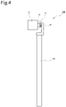
- Fig. 4 is a diagram illustrating a usage example in a case where a hanging door is mounted to the rolling guide device according to the first embodiment. Also, Fig.
- Fig. 5 is a diagram illustrating an alteration of the rolling guide device according to the first embodiment and a usage example in a case where a door body to be used for a railway car is mounted to the rolling guide device according to the alteration.
- Fig. 6 is a diagram illustrating an example configuration of a railway car with the rolling guide device illustrated in Fig. 5 installed therein.
- the rolling guide device 10 enables configuring an opening and closing mechanism 100 for a hanging door 52 to be used in a house by fixedly installing the track rail 11 on a slide door frame 51 and installing the hanging door 52 on the moving slider 21.
- the rolling guide device 10 according to the first embodiment enables the first wheels 31 and the second rollers 41 to cooperatively receive a roll moment Mc and is thus capable of properly and stably guiding the hanging door 52.
- first wheels 31 installed, install a large moving slider 21 on a single track rail 11 or install a plurality of moving sliders 21 on a single track rail 11.
- eight first wheels 31 are installed and a long moving slider 21 is installed on a single track rail 11.
- four first wheels 31 on respective positions on each of the right and left sides of the long moving slider 21, that is, a total of eight first wheels 31 are disposed.
- a single door body 53 for a railway car is installed using the long moving slider 21.
- the rolling guide device 10 of the alteration illustrated in Fig. 5 is usable as an opening and closing mechanism 200 for opening and closing an entrance of a railway car such as one illustrated in Fig. 6 .
- the track rail 11 of the rolling guide device 10 according to the alteration is installed on a door frame 55 (corresponding to a body of a railway car) and a door body 53 is installed on the moving slider 21, enabling an operation of opening and closing the door body 53 from/to the door frame 55 (corresponding to a body of a railway car).
- use of the rolling guide device 10 for a railway car enables provision of an effect of providing a wide range in size of the door body 53 because the rolling guide device 10 has a very compact configuration such that the second rollers 41 do not project from the outer periphery of the moving slider 21.
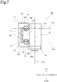
- Fig. 7 is a left side view of a rolling guide device according to a second embodiment from the left side.
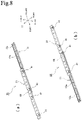
- Fig. 8 includes outer appearance perspective views of the rolling guide device according to the second embodiment from the diagonally upper left side.
- Fig. 8(a) illustrates a state in which a moving slider has been moved to the left side relative to a track rail
- Fig. 8(b) illustrates a state in which the moving slider has been moved to the right side relative to the track rail.
- Fig. 9 is a transparent perspective view of the rolling guide device according to the second embodiment with the moving slider removed.
- members that are the same as or similar to those of the first embodiment described with reference to Figs. 1 to 3 are provided with reference numerals that are the same as those of the first embodiment and description of such members is omitted.
- a rolling guide device 60 includes a track rail 11, which serves as a track member, a moving slider 21, which serves as a moving member installed in such a manner as to be capable of reciprocating movement along a longitudinal direction of the track rail 11 (that is, a direction perpendicular to the sheet of Fig. 7 ), a multitude of first balls 61, which serve as first rolling elements rollably disposed between the track rail 11 and the moving slider 21, and second rollers 41, which each serve as a second rolling element rollably disposed on the lower surface side of the moving slider 21.
- the track rail 11 is a long member extending in the longitudinal direction and having a substantial turned U-shape in cross-section.
- the track rail 11 of the second embodiment includes a mounting surface portion 12 extending in the up-down direction, an upper wall portion 63, which serves as a wall portion according to the present invention, the upper wall portion 63 extending frontward from an upper end of the mounting surface portion 12, and a lower wall portion 64, which serves as a wall portion according to the present invention, the lower wall portion 64 extending frontward from a lower end of the mounting surface portion 12, in side view.
- a first ball upper rolling surface 63a which serves as a rolling element rolling surface according to the present invention, the first ball upper rolling surface 63a being in contact with ball outer circumferential surfaces of first balls 61, is formed.
- a first ball lower rolling surface 64a which serves as a rolling element rolling surface according to the present invention, the first ball lower rolling surface 64a being in contact with ball outer circumferential surfaces of first balls 61, is formed.
- the first ball upper rolling surface 63a and the first ball lower rolling surface 64a are disposed in such a manner as to face each other in side view.
- the track rail 11 of the second embodiment is a member that serves as a base for mounting of the rolling guide device 60. Therefore, in the second embodiment, mounting holes 12a such as bolt holes are formed in the mounting surface portion 12 included in the track rail 11, enabling the track rail 11 to be fixedly installed on a mounting base surface of, e.g., a base or a door frame using the mounting holes 12a.
- the track rail 11 of the second embodiment is formed by plastically deforming a metal material via a drawing process and forming a part of the track rail 11 that the later-described second rollers 41 come into contact with, that is, a part of a lower open end portion 64b of the substantial turned U-shape of the track rail 11 (outer end portion according to the present invention) as a flat surface subjected to a grinding process.
- the open end portion 64b on which the second rollers 41 roll is left in the state of the open end portion 64b subjected to the drawing process without being subjected to the grinding process.
- the moving slider 21 is configured by a combination of two members that are a slider block 65 and a mounting block 66.
- the slider block 65 is a long member disposed in the longitudinal direction of the track rail 11, and ball rolling grooves 65a, 65b that face the first ball upper rolling surface 63a and the first ball lower rolling surface 64a, respectively, are formed on upper and lower surface of the slider block 65, respectively.
- the multitude of first balls 61 are rollably disposed in two load ball rolling channels extending in the right-left direction, which are a load ball rolling channel configured by the first ball upper rolling surface 63a and the ball rolling groove 65a and a load ball rolling channel configured by the first ball lower rolling surface 64a and the ball rolling groove 65b, enabling relative reciprocating movement of the slider block 65 (moving slider 21) along the longitudinal direction of the track rail 11.
- the mounting block 66 in the mounting block 66 four second rollers 41 are rollably disposed on the lower surface side. Also, a movable member to be guided and moved by the rolling guide device 60 can be installed on the front surface side of the mounting block 66.
- the slider block 65 is disposed in an inner space 15 surrounded by the mounting surface portion 12, the upper wall portion 63 and the lower wall portion 64, and furthermore, the multitude of first balls 61 are rollably disposed inside the load ball rolling channel configured by the first ball upper rolling surface 63a and the ball rolling groove 65a and the load ball rolling channel configured by the first ball lower rolling surface 64a and the ball rolling groove 65b. Therefore, reciprocating movement of the moving slider 21 relative to the track rail 11 is enabled by the multitude of first balls 61 rolling.
- the multitude of first balls 61 are aligned by a retainer 67 formed of resin or metal, and can roll in the aligned state in the two load ball rolling channels.
- each of rotation center lines 61a of the above-described first balls 61 is a horizontal line along the front-rear direction.
- each of rotation center lines 41a of the second rollers 41 disposed on the lower surface side of the moving slider 21 is a vertical line along the up-down direction.
- each second roller 41 of the second embodiment has a rotation center axis 41a in a direction substantially orthogonal to the rotation center axes 61a of the first balls 61.
- each second roller 41 is configured to roll in contact with the lower open end portion 64b of the substantial turned U-shape of the track rail 11.
- each second roller 41 is configured to roll in contact with the lower open end portion 64b of the substantial turned U-shape of the track rail 11, and thus, even if a roll moment Mc is applied to the moving slider 21, the second rollers 41 can properly receive the moment Mc.
- the second embodiment enables enhancement in rigidity against a roll moment Mc, and thus enables provision of the rolling guide device 60 capable of performing a proper and stable guiding operation even if unbalanced weight is applied to the moving slider 21.
- the second rollers 41 are disposed in such a manner as to not project from an outer periphery of the moving slider 21, and thus, the rolling guide device 60 according to the second embodiment has a very compact configuration as a whole.
- Such configuration produces an effect of minimization of installation space, and thus, the rolling guide device 60 according to the second embodiment has an advantage of a large scope of applicability.
- first wheels 31, which serve as first rolling elements, and the second rollers 41, which each serve as a second rolling element, are configured as wheels or rollers as an example.
- a cam follower or a roller follower can be employed instead of the wheel or the roller above.
- first rolling elements are the first balls 61 and the second rolling elements are the second rollers 41 as an example.
- second rolling elements are the second rollers 41.
- any of a wheel, a roller, a cam follower or a roller follower can be employed or a configuration resulting from arbitrary combination of a wheel, a roller, a cam follower or a roller follower can be employed.
- the rolling guide device 10 is used for the opening and closing mechanism 100 for a hanging door to be used in a house or the opening and closing mechanism 200 for a door body to be used in a railway car as examples
- the rolling guide device 60 according to the second embodiment can also be used for the opening and closing mechanisms 100, 200.
- each second roller 41 is configured to roll in contact with the lower open end portion 14b, 64b of the substantial C-shape or the substantial turned U-shape of the track rail 11.
- each second roller 41 which is a second rolling element of the present invention, may be configured to be in contact with an upper open end portion of the substantial C-shape or the substantial turned U-shape of the track rail 11.
- a second rolling element of the present invention is a roller (second roller 41) as an example; however, a second rolling element of the present invention may be a ball. Then, a ball employed as a second rolling element of the present invention may be one ball, a series of balls or a plurality of circulating balls.
- 10 rolling guide device (according to first embodiment and alteration thereof), 11 track rail (track member), 12 mounting surface portion, 12a mounting hole, 13 upper wall portion (wall portion), 13a first wheel upper rolling surface (rolling element rolling surface), 14 lower wall portion (wall portion), 14a first wheel lower rolling surface (rolling element rolling surface), 14b lower open end portion (outer end portion), 15 inner space (inside space), 21 moving slider (moving member), 31 first wheel (first rolling element), 31a rotation center line, 41 second roller (second rolling element), 41a rotation center line, 51 slide door frame (door frame), 52 hanging door (door body), 53 door body, 55 door frame, 60 rolling guide device (according to second embodiment), 61 first ball (first rolling element), 61a rotation center line, 63 upper wall portion (wall portion), 63a first ball upper rolling surface (rolling element rolling surface), 64 lower wall portion (wall portion), 64a first ball lower rolling surface (rolling element rolling surface), 64b lower open end portion (outer end portion), 65 slider block, 65a, 65b ball rolling groove,
Landscapes
- Engineering & Computer Science (AREA)
- Mechanical Engineering (AREA)
- General Engineering & Computer Science (AREA)
- Civil Engineering (AREA)
- Structural Engineering (AREA)
- Bearings For Parts Moving Linearly (AREA)
- Rolling Contact Bearings (AREA)
Abstract
Description
- The present invention relates to a rolling guide device and an opening and closing mechanism using the rolling guide device.
- Conventionally, a rolling guide device including a track rail extending in a longitudinal direction and having a substantial C-shape in cross-section, a slider installed in such a manner as to be capable of reciprocating movement along the longitudinal direction of the track rail, and a plurality of rolling elements rollably disposed in an inner space of the substantial C-shape of the track rail between the track rail and the slider to guide reciprocating movement of the slider relative to the track rail has been publicly known.
- As a specific example of this type of rolling guide device, there is a linear bearing disclosed in
Japanese Patent No. 3292459 Japanese Patent No. 3292459 - However, conventional rolling guide devices represented by the linear bearing disclosed in the aforementioned
Japanese Patent No. 3292459 - The present invention has been made in view of the above case in the conventional techniques, and an object of the present invention is to provide a rolling guide device capable of performing a proper and stable guiding operation even if unbalanced weight is applied to a moving member, through enhancement in rigidity against a roll moment Mc.
- A rolling guide device according to the present invention is a rolling guide device including: a track member that is a long member extending in a longitudinal direction, the track member including a mounting surface portion that serves as a base for mounting to an external member and a pair of wall portions provided in such a manner as to stand from respective opposite end portions of the mounting surface portion toward one side; a moving member installed in such a manner as to be capable of reciprocating movement along the longitudinal direction of the track member; and a plurality of first rolling elements rollably disposed inside a space between the track member and the moving member, the space being surrounded by the mounting surface portion and the pair of wall portions included in the track member, to guide reciprocating movement of the moving member relative to the track member, wherein a rolling element rolling surface that is in contact with a rolling element outer circumferential surface of a first rolling element from among the first rolling elements is formed at each of respective wall surfaces of the pair of wall portions, the wall surfaces facing each other, the rolling element rolling surfaces formed at the pair of wall portions, respectively, are each formed as a circular arc groove including a single circular arc, to allow each of the first rolling elements and the corresponding one of the rolling element rolling surfaces to be in contact with each other at one point, and the moving member includes a second rolling element that rolls in contact with an outer end portion of one wall portion of the pair of wall portions included in the track member.
- Also, the present invention includes an opening and closing mechanism including the above rolling guide device, the track member of the rolling guide device being installed on a door frame, a door body being installed on the moving member, to allow the opening and closing mechanism to perform an operation of opening and closing the door body relative to the door frame.
- The present invention enables provision of a rolling guide device capable of performing a proper and stable guiding operation even if unbalanced weight is applied to a moving member, through enhancement in rigidity against a roll moment Mc.
-
-
Fig. 1 is a transparent view of a rolling guide device according to a first embodiment from the front side. -
Fig. 2 is a transparent view of the rolling guide device according to the first embodiment from the left side. -
Fig. 3 includes schematic diagrams for describing a manner of a first wheel rolling on a first wheel upper rolling surface and a first wheel lower rolling surface in the first embodiment. -
Fig. 4 is a diagram illustrating a usage example in a case where a hanging door is mounted to the rolling guide device according to the first embodiment. -
Fig. 5 is a diagram illustrating an alteration of the rolling guide device according to the first embodiment and a usage example in a case where a door body to be used in a railway car is mounted to the rolling guide device according to the alteration. -
Fig. 6 is a diagram illustrating an example configuration of a railway car with the rolling guide device illustrated inFig. 5 installed therein. -
Fig. 7 is a left side view of a rolling guide device according to a second embodiment. -
Fig. 8 includes outer appearance perspective views of the rolling guide device according to the second embodiment from the diagonally upper left side. -
Fig. 9 is a transparent perspective view of the rolling guide device according to the second embodiment with a moving slider removed. - Preferable embodiments for carrying out the present invention will be described below with reference to the drawings. Note that the following embodiments are not intended to limit the invention according to the claims and each of all of combinations of features described in the embodiments is not necessarily essential for the means for solving the problems in the invention.
- First, a basic configuration of a
rolling guide device 10 according to a first embodiment will be described with reference toFigs. 1 and2 . Here,Fig. 1 is a transparent view of a rolling guide device according to a first embodiment from the front side andFig. 2 is a transparent view of the rolling guide device according to the first embodiment from the left side. Note that in the present description, for convenience of description, directions in therolling guide device 10 are defined as illustrated inFigs. 1 and2 . However, these directions are not those indicating directions when therolling guide device 10 according to the first embodiment is in use, and therolling guide device 10 according to the first embodiment can be used in any position. In other words, the directions "front", "rear", "up", "down", "right" and "left" indicated inFigs. 1 and2 are definitely those determined for convenience of description. - As illustrated in
Figs. 1 and2 , therolling guide device 10 according to the first embodiment includes atrack rail 11, which serves as a track member, a movingslider 21, which serves as a moving member installed in such a manner as to be capable of reciprocating movement along a longitudinal direction of the track rail 11 (that is, the right-left direction inFig. 1 ),first wheels 31, which each serve as a first rolling element rollably disposed between thetrack rail 11 and the movingslider 21, andsecond rollers 41, which each serve as a second rolling element rollably disposed on the lower surface side of the movingslider 21. - The
track rail 11 is a long member extending in the longitudinal direction and having a substantial C-shape in cross-section. As illustrated inFig. 2 , thetrack rail 11 of the first embodiment includes amounting surface portion 12 extending in the up-down direction, anupper wall portion 13, which serves as a wall portion according to the present invention, theupper wall portion 13 extending frontward from an upper end of themounting surface portion 12, and alower wall portion 14, which serves as a wall portion according to the present invention, thelower wall portion 14 extending frontward from a lower end of themounting surface portion 12, in side view. - On the lower surface side of the
upper wall portion 13, a first wheel upper rollingsurface 13a, which serves as a rolling element rolling surface according to the present invention, the first wheel upper rollingsurface 13a being in contact with a wheel outer circumferential surface of a relevantfirst wheel 31, is formed. Likewise, on the upper surface side of thelower wall portion 14, a first wheel lowerrolling surface 14a, which serves as a rolling element rolling surface according to the present invention, the first wheel lowerrolling surface 14a being in contact with a wheel outer circumferential surface of each of relevantfirst wheels 31, is formed. The first wheel upper rollingsurface 13a and the first wheel lowerrolling surface 14a are disposed in such a manner as to face each other in side view. Then, thefirst wheels 31 are rollably disposed in aninner space 15 surrounded by themounting surface portion 12, theupper wall portion 13 and the lower wall portion 14 (inside a space according to the present invention). - The
track rail 11 of the first embodiment is formed in the aforementioned contour shape by plastically deforming a metal material via a drawing process and forming a part of thetrack rail 11 that the later-describedsecond rollers 41 come into contact with, that is, a part of a loweropen end portion 14b of the substantial C-shape of the track rail 11 (outer end portion according to the present invention), as a flat surface subjected to a grinding process. However, a method for forming thetrack rail 11 is not limited to a combination of a drawing process and a grinding process. For example, the outer appearance shape may be formed by performing, e.g., a grinding process or a cutting process of a metal material or the contour shape may be formed by plastically deforming a metal material via a drawing process and subsequently performing a thermal treatment process to control a surface hardness and internal quality and then performing, e.g., a grinding process. In other words, the contour shape of thetrack rail 11, which is a track member of the present invention, can be formed using any process method. - Also, the
track rail 11 of the first embodiment is a member that serves as a base for mounting of therolling guide device 10. Therefore, in the first embodiment, mountingholes 12a such as bolt holes are formed in themounting surface portion 12 included in thetrack rail 11, enabling thetrack rail 11 to be fixedly installed on a mounting base surface of, e.g., a base or a door frame using themounting holes 12a. - As illustrated in
Figs. 1 and2 , the movingslider 21 is a block-like member having a substantially rectangular shape and is disposed in such a manner as to be capable of reciprocating movement along the longitudinal direction of thetrack rail 11. In the movingslider 21 of the first embodiment, threefirst wheels 31 are rollably disposed on the rear surface side and twosecond rollers 41 are rollably disposed on the lower surface side. Also, a movable member to be guided and moved by therolling guide device 10 can be installed on the front surface side of the movingslider 21. - Each of the
first wheels 31 is a member rollably disposed in theinner space 15 of the substantial C-shape of thetrack rail 11, between thetrack rail 11 and the movingslider 21, to guide reciprocating movement of themoving slider 21 relative to thetrack rail 11. - More specifically, as the
first wheels 31 of the first embodiment, threefirst wheels 31 are rollably disposed on the rear surface side of the movingslider 21. Then, as is clear with reference to the comparison betweenFigs. 1 and2 , onefirst wheel 31 located at a center from among the threefirst wheels 31 is disposed in such a manner as to be in contact with the first wheel upper rollingsurface 13a and be not in contact with, but be spaced from, the first wheel lowerrolling surface 14a. On the other hand, twofirst wheels 31 located at the right and the left from among the threefirst wheels 31 are disposed in such a manner as to be in contact with the first wheel lower rollingsurface 14a and be not in contact with, but be spaced from, the first wheel upper rollingsurface 13a. As a result of the threefirst wheels 31 are disposed in such a manner as to be staggered in the up-down direction in front view in this way, for example, when the movingslider 21 moves to the right side of the sheet relative to thetrack rail 11 inFig. 1 , the onefirst wheel 31 located at the center rotates counterclockwise in the sheet ofFig. 1 and the twofirst wheels 31 located at the right and the left rotate clockwise in the sheet ofFig. 1 . Also, conversely, when themoving slider 21 moves to the left side of the sheet relative to thetrack rail 11 inFig. 1 , the onefirst wheel 31 located at the center rotates clockwise in the sheet ofFig. 1 and the twofirst wheels 31 located at the right and the left rotate counterclockwise in the sheet ofFig. 1 . In this way, the threefirst wheels 31 being disposed in such a manner as to be staggered in the up-down direction in front view enables the movingslider 21 that makes relative linear movement along the longitudinal direction of thetrack rail 11 to make favorable linear reciprocating movement while properly receiving a moment load. - Note that in the first embodiment illustrated in
Figs. 1 and2 , the onefirst wheel 31 located at the center is disposed in contact with the first wheel upper rollingsurface 13a and the twofirst wheels 31 located at the right and the left are disposed in contact with the first wheel lowerrolling surface 14a. However, the scope of the present invention is not limited to this example, and for example, a configuration in which the onefirst wheel 31 located at the center is disposed in contact with the first wheel lowerrolling surface 14a and the twofirst wheels 31 located at the right and the left are disposed in contact with the first wheel upper rollingsurface 13a, which is a disposition opposite to the first embodiment, may be employed. - Also, in the present invention, it is possible to employ an example configuration in which four or more
first wheels 31 are disposed on the rear surface side of the movingslider 21; however, in the case of this example configuration, it is preferable that adjacentfirst wheels 31 be disposed in contact with the first wheel upper rollingsurface 13a and the first wheel lowerrolling surface 14a alternately. - Furthermore, "wheel" in the present invention refers to a wheel member rotatably mounted on a rotation shaft, and may be one including a rolling contact surface of contact with a counterpart member, the rolling contact surface including any of a horizontal surface, a projecting curve surface and a recessed curve surface. In the present embodiment, a case where the rolling contact surface of the
first wheel 31 is formed as a projecting curve surface is illustrated as an example (seeFig. 2 ). - Here, a relationship between the
first wheels 31 and the first wheel upper rollingsurface 13a and the first wheel lowerrolling surface 14a will be described withFig. 3 added to the reference drawings.Fig. 3 includes schematic diagrams for describing a manner of a first wheel rolling on a first wheel upper rolling surface and a first wheel lower rolling surface in the first embodiment.Fig. 3(a) illustrates a state in which no roll moment Mc is applied to the movingslider 21,Fig. 3(b) illustrates a state in which a roll moment Mc is applied to the movingslider 21 andFig. 3(c) is an enlarged view of a dashed line region indicated by sign α inFig. 3(b) . - In the first embodiment, the first wheel
upper rolling surface 13a and the first wheellower rolling surface 14a each have a shape of a circular arc groove formed of a single circular arc in cross-section. In other words, a radius of curvature of each of the first wheelupper rolling surface 13a and the first wheellower rolling surface 14a is slightly larger than a radius of curvature of the rolling contact surface of eachfirst wheel 31. Therefore, eachfirst wheel 31 according to the first embodiment comes into contact with the first wheelupper rolling surface 13a and the first wheellower rolling surface 14a at one point. - Then, as illustrated in
Fig. 3(a) , where no roll moment Mc is applied to the movingslider 21, a line L1 indicating a roll direction orthogonal to a rotation center line of thefirst wheel 31 is a vertical line extending in the up-down direction, and respective contact points P1 of contact between thefirst wheels 31 and the first wheelupper rolling surface 13a and the first wheellower rolling surface 14a are located at respective centers of groove bottoms of the circular arc grooves forming the first wheelupper rolling surface 13a and the first wheellower rolling surface 14a. - Upon application of a roll moment Mc to the moving
slider 21 in the state illustrated inFig. 3(a) , as illustrated inFig. 3(b) , thefirst wheels 31 are inclined in the direction in which the moment Mc is applied (clockwise direction in the sheet ofFig. 3(b) ). In other words, the line L1 indicating the roll direction orthogonal to the rotation center line of thefirst wheel 31 is inclined to the position of a line L2. In this case, since each of the first wheelupper rolling surface 13a and the first wheellower rolling surface 14a has a shape of a circular arc groove formed of a single circular arc in cross-section, the contact points move from the contact points P1 to contact points P2 according to the clockwise inclination of thefirst wheels 31. In other words, in the rollingguide device 10 according to the first embodiment, even if a roll moment Mc is applied to the movingslider 21, the contact points shift according to the moment Mc and each of thefirst wheels 31 and the first wheelupper rolling surface 13a and the first wheellower rolling surface 14a are consistently in contact with each other at one point, enabling a favorable rolling motion with a smaller differential slippage amount to be consistently provided. - Referring to
Fig. 2 , in the rollingguide device 10 according to the first embodiment, arotation center line 31a of each of thefirst wheels 31 described above is a horizontal line along the front-rear direction. On the other hand, arotation center line 41a of each of thesecond rollers 41 disposed on the lower surface side of the movingslider 21 is a vertical line extending along the up-down direction. In other words, eachsecond roller 41 according to the first embodiment has arotation center axis 41a in a direction substantially orthogonal to the rotation center axes 31a of thefirst wheels 31. - Furthermore, each
second roller 41 is configured to roll in contact with the loweropen end portion 14b of the substantial C-shape of thetrack rail 11. As described above, in the first embodiment, the first wheelupper rolling surface 13a and the first wheellower rolling surface 14a that are in contact with thefirst wheels 31 are each configured as a circular arc groove, and thus, application of an external load to the movingslider 21 causes the contact points P1, P2 to consistently shift. However, in the first embodiment, thesecond rollers 41 are each configured to roll in contact with the loweropen end portion 14b of the substantial C-shape of thetrack rail 11, and thus properly compensate for the shifting of the contact points P1, P2, enabling thefirst wheels 31 and thesecond rollers 41 to cooperatively receive a roll moment Mc. In other words, in the first embodiment, a combination of two configurations, the configuration of thefirst wheels 31 and the first wheelupper rolling surface 13a and the first wheellower rolling surface 14a and the configuration of thesecond rollers 41 and the loweropen end portion 14b of the substantial C-shape of thetrack rail 11, enables enhancement in rigidity against a roll moment Mc, and thus enables provision of the rollingguide device 10 capable of performing a proper and stable guiding operation even if unbalanced weight is applied to the movingslider 21. - Also, in the first embodiment, the first wheel
upper rolling surface 13a and the first wheellower rolling surface 14a that are in contact with thefirst wheels 31 are each configured as a circular arc groove, and thus, a merit of mounting error absorption shows up as a displacement depending on the counterpart of the mounting. Therefore, in particular, in the case of the first embodiment in which circular arc grooves are employed for the first wheelupper rolling surface 13a and the first wheellower rolling surface 14a that are in contact with thefirst wheels 31, it is more preferable that thesecond rollers 41 capable of favorably receiving a roll moment Mc be provided. - In the first embodiment, it is assumed that the
open end portion 14b of thetrack rail 11, theopen end portion 14b being in contact with thesecond rollers 41, is formed as a flat surface by subjecting a metal material to a drawing process and a subsequent grinding process. However, it is also possible that theopen end portion 14b on which thesecond rollers 41 roll is left in the state of theopen end portion 14b subjected to the drawing process without being subjected to the grinding process. - Also, as illustrated in
Figs. 1 and2 , in the first embodiment, thesecond rollers 41 are disposed in such a manner as to not project from an outer periphery of the movingslider 21, and thus, the rollingguide device 10 according to the first embodiment has a very compact configuration as a whole. Such configuration produces an effect of minimization of installation space, and thus the rollingguide device 10 according to the first embodiment has an advantage of a large scope of applicability. - In the rolling
guide device 10 according to the first embodiment, it is preferable that rotation shafts offirst wheels 31 and/orsecond rollers 41 be made to be eccentric shafts to enable adjustment in position of thefirst wheels 31 and/or thesecond rollers 41 through rotation of the eccentric shafts. For example, as illustrated inFig. 1 , in the first embodiment, threefirst wheels 31 are disposed side by side in the right-left direction; however, rotation shafts of the twofirst wheels 31 disposed at the right and the left are made to be fixed shafts and a rotation shaft of the onefirst wheel 31 disposed at the center is made to be an eccentric shaft to enable making, e.g., preload adjustment of the threefirst wheels 31 for thetrack rail 11 by moving the position of thefirst wheel 31 disposed at the center upward. Also, it is possible to perform, e.g., preload adjustment of thesecond rollers 41 for thetrack rail 11 by making the rotation shafts of thesecond rollers 41 as eccentric shafts and performing adjustment in position of thesecond rollers 41 in the front-rear direction by rotating the eccentric shafts to arbitrary positions. - The rolling
guide device 10 according to the first embodiment has been described above. This rollingguide device 10 is suitable for use in, for example, an opening and closing mechanism of a hanging door to be used in a house or an opening and closing mechanism of a door body to be used in a railway car. Therefore, next, an example of industrial application of the rollingguide device 10 according to the first embodiment will be described with reference toFigs. 4 to 6 . Here,Fig. 4 is a diagram illustrating a usage example in a case where a hanging door is mounted to the rolling guide device according to the first embodiment. Also,Fig. 5 is a diagram illustrating an alteration of the rolling guide device according to the first embodiment and a usage example in a case where a door body to be used for a railway car is mounted to the rolling guide device according to the alteration. Furthermore,Fig. 6 is a diagram illustrating an example configuration of a railway car with the rolling guide device illustrated inFig. 5 installed therein. - As illustrated in
Fig. 4 , the rollingguide device 10 according to the first embodiment enables configuring an opening andclosing mechanism 100 for a hangingdoor 52 to be used in a house by fixedly installing thetrack rail 11 on aslide door frame 51 and installing the hangingdoor 52 on the movingslider 21. In the case of the hangingdoor 52, unbalanced weight is applied to the movingslider 21; however, the rollingguide device 10 according to the first embodiment enables thefirst wheels 31 and thesecond rollers 41 to cooperatively receive a roll moment Mc and is thus capable of properly and stably guiding the hangingdoor 52. - Also, as illustrated in
Fig. 5 , for the rollingguide device 10 according to the first embodiment, it is possible to increase the number offirst wheels 31 installed, install a large movingslider 21 on asingle track rail 11 or install a plurality of movingsliders 21 on asingle track rail 11. For example, in the case of the alteration illustrated inFig. 5 , eightfirst wheels 31 are installed and a long movingslider 21 is installed on asingle track rail 11. Then, fourfirst wheels 31 on respective positions on each of the right and left sides of the long movingslider 21, that is, a total of eightfirst wheels 31 are disposed. Furthermore, asingle door body 53 for a railway car is installed using the long movingslider 21. - The rolling
guide device 10 of the alteration illustrated inFig. 5 is usable as an opening andclosing mechanism 200 for opening and closing an entrance of a railway car such as one illustrated inFig. 6 . In this opening andclosing mechanism 200, thetrack rail 11 of the rollingguide device 10 according to the alteration is installed on a door frame 55 (corresponding to a body of a railway car) and adoor body 53 is installed on the movingslider 21, enabling an operation of opening and closing thedoor body 53 from/to the door frame 55 (corresponding to a body of a railway car). In particular, use of the rollingguide device 10 for a railway car enables provision of an effect of providing a wide range in size of thedoor body 53 because the rollingguide device 10 has a very compact configuration such that thesecond rollers 41 do not project from the outer periphery of the movingslider 21. - The configuration of the rolling
guide device 10 according to the first embodiment and an alternation thereof have been described above. Next, another embodiment of the rolling guide device according to the present invention will be described with reference toFigs. 7 to 9 . -
Fig. 7 is a left side view of a rolling guide device according to a second embodiment from the left side. Also,Fig. 8 includes outer appearance perspective views of the rolling guide device according to the second embodiment from the diagonally upper left side.Fig. 8(a) illustrates a state in which a moving slider has been moved to the left side relative to a track rail andFig. 8(b) illustrates a state in which the moving slider has been moved to the right side relative to the track rail. Furthermore,Fig. 9 is a transparent perspective view of the rolling guide device according to the second embodiment with the moving slider removed. InFigs. 7 to 9 , members that are the same as or similar to those of the first embodiment described with reference toFigs. 1 to 3 are provided with reference numerals that are the same as those of the first embodiment and description of such members is omitted. - As illustrated in
Fig. 7 , a rollingguide device 60 according to a second embodiment includes atrack rail 11, which serves as a track member, a movingslider 21, which serves as a moving member installed in such a manner as to be capable of reciprocating movement along a longitudinal direction of the track rail 11 (that is, a direction perpendicular to the sheet ofFig. 7 ), a multitude offirst balls 61, which serve as first rolling elements rollably disposed between thetrack rail 11 and the movingslider 21, andsecond rollers 41, which each serve as a second rolling element rollably disposed on the lower surface side of the movingslider 21. - The
track rail 11 is a long member extending in the longitudinal direction and having a substantial turned U-shape in cross-section. As illustrated inFig. 7 , thetrack rail 11 of the second embodiment includes a mountingsurface portion 12 extending in the up-down direction, anupper wall portion 63, which serves as a wall portion according to the present invention, theupper wall portion 63 extending frontward from an upper end of the mountingsurface portion 12, and alower wall portion 64, which serves as a wall portion according to the present invention, thelower wall portion 64 extending frontward from a lower end of the mountingsurface portion 12, in side view. - On the lower surface side of the
upper wall portion 63, a first ball upper rollingsurface 63a, which serves as a rolling element rolling surface according to the present invention, the first ball upper rollingsurface 63a being in contact with ball outer circumferential surfaces offirst balls 61, is formed. Likewise, on the upper surface side of thelower wall portion 64, a first ball lower rollingsurface 64a, which serves as a rolling element rolling surface according to the present invention, the first ball lower rollingsurface 64a being in contact with ball outer circumferential surfaces offirst balls 61, is formed. The first ball upper rollingsurface 63a and the first ball lower rollingsurface 64a are disposed in such a manner as to face each other in side view. - Also, the
track rail 11 of the second embodiment is a member that serves as a base for mounting of the rollingguide device 60. Therefore, in the second embodiment, mountingholes 12a such as bolt holes are formed in the mountingsurface portion 12 included in thetrack rail 11, enabling thetrack rail 11 to be fixedly installed on a mounting base surface of, e.g., a base or a door frame using the mountingholes 12a. - Furthermore, the
track rail 11 of the second embodiment is formed by plastically deforming a metal material via a drawing process and forming a part of thetrack rail 11 that the later-describedsecond rollers 41 come into contact with, that is, a part of a loweropen end portion 64b of the substantial turned U-shape of the track rail 11 (outer end portion according to the present invention) as a flat surface subjected to a grinding process. However, it is also possible that theopen end portion 64b on which thesecond rollers 41 roll is left in the state of theopen end portion 64b subjected to the drawing process without being subjected to the grinding process. - As illustrated in
Fig. 7 , the movingslider 21 according to the second embodiment is configured by a combination of two members that are aslider block 65 and a mountingblock 66. - As illustrated in
Figs. 7 and9 , theslider block 65 is a long member disposed in the longitudinal direction of thetrack rail 11, andball rolling grooves surface 63a and the first ball lower rollingsurface 64a, respectively, are formed on upper and lower surface of theslider block 65, respectively. Then, the multitude offirst balls 61 are rollably disposed in two load ball rolling channels extending in the right-left direction, which are a load ball rolling channel configured by the first ball upper rollingsurface 63a and theball rolling groove 65a and a load ball rolling channel configured by the first ball lower rollingsurface 64a and theball rolling groove 65b, enabling relative reciprocating movement of the slider block 65 (moving slider 21) along the longitudinal direction of thetrack rail 11. - As illustrated in
Figs. 7 and8 , in the mountingblock 66 foursecond rollers 41 are rollably disposed on the lower surface side. Also, a movable member to be guided and moved by the rollingguide device 60 can be installed on the front surface side of the mountingblock 66. - According to the above, the
slider block 65 is disposed in aninner space 15 surrounded by the mountingsurface portion 12, theupper wall portion 63 and thelower wall portion 64, and furthermore, the multitude offirst balls 61 are rollably disposed inside the load ball rolling channel configured by the first ball upper rollingsurface 63a and theball rolling groove 65a and the load ball rolling channel configured by the first ball lower rollingsurface 64a and theball rolling groove 65b. Therefore, reciprocating movement of the movingslider 21 relative to thetrack rail 11 is enabled by the multitude offirst balls 61 rolling. - As illustrated in
Fig. 7 , the multitude offirst balls 61 are aligned by aretainer 67 formed of resin or metal, and can roll in the aligned state in the two load ball rolling channels. - Referring to
Fig. 7 , in the rollingguide device 60 according to the second embodiment, each ofrotation center lines 61a of the above-describedfirst balls 61 is a horizontal line along the front-rear direction. On the other hand, each ofrotation center lines 41a of thesecond rollers 41 disposed on the lower surface side of the movingslider 21 is a vertical line along the up-down direction. In other words, eachsecond roller 41 of the second embodiment has arotation center axis 41a in a direction substantially orthogonal to the rotation center axes 61a of thefirst balls 61. - Furthermore, each
second roller 41 is configured to roll in contact with the loweropen end portion 64b of the substantial turned U-shape of thetrack rail 11. In this way, in the second embodiment, eachsecond roller 41 is configured to roll in contact with the loweropen end portion 64b of the substantial turned U-shape of thetrack rail 11, and thus, even if a roll moment Mc is applied to the movingslider 21, thesecond rollers 41 can properly receive the moment Mc. In other words, the second embodiment enables enhancement in rigidity against a roll moment Mc, and thus enables provision of the rollingguide device 60 capable of performing a proper and stable guiding operation even if unbalanced weight is applied to the movingslider 21. - Also, in the second embodiment, as illustrated in
Fig. 8 , thesecond rollers 41 are disposed in such a manner as to not project from an outer periphery of the movingslider 21, and thus, the rollingguide device 60 according to the second embodiment has a very compact configuration as a whole. Such configuration produces an effect of minimization of installation space, and thus, the rollingguide device 60 according to the second embodiment has an advantage of a large scope of applicability. - Although preferable embodiments of the present invention have been described above, the technical scope of the present invention is not limited to the scope of the description in the embodiments. Various changes or modifications of the embodiments are possible.
- For example, the above first embodiment has been described taking a case where the
first wheels 31, which serve as first rolling elements, and thesecond rollers 41, which each serve as a second rolling element, are configured as wheels or rollers as an example. However, for a first rolling element and a second rolling element of the present invention, a cam follower or a roller follower can be employed instead of the wheel or the roller above. - Also, for example, the above second embodiment has been described taking a case where the first rolling elements are the
first balls 61 and the second rolling elements are thesecond rollers 41 as an example. However, for a first rolling element and a second rolling element of the present invention, any of a wheel, a roller, a cam follower or a roller follower can be employed or a configuration resulting from arbitrary combination of a wheel, a roller, a cam follower or a roller follower can be employed. - Also, although the above first embodiment has been described taking cases where the rolling
guide device 10 is used for the opening andclosing mechanism 100 for a hanging door to be used in a house or the opening andclosing mechanism 200 for a door body to be used in a railway car as examples, the rollingguide device 60 according to the second embodiment can also be used for the opening andclosing mechanisms - Also, for example, in each of the first and second embodiments above, each
second roller 41 is configured to roll in contact with the loweropen end portion track rail 11. However, eachsecond roller 41, which is a second rolling element of the present invention, may be configured to be in contact with an upper open end portion of the substantial C-shape or the substantial turned U-shape of thetrack rail 11. - Also, for example, the above first and second embodiments have been described taking a case where a second rolling element of the present invention is a roller (second roller 41) as an example; however, a second rolling element of the present invention may be a ball. Then, a ball employed as a second rolling element of the present invention may be one ball, a series of balls or a plurality of circulating balls.
- It is clear from the statement of the claims that a mode with such changes or modifications made thereto can also be embraced within the technical scope of the present invention.
- 10 rolling guide device (according to first embodiment and alteration thereof), 11 track rail (track member), 12 mounting surface portion, 12a mounting hole, 13 upper wall portion (wall portion), 13a first wheel upper rolling surface (rolling element rolling surface), 14 lower wall portion (wall portion), 14a first wheel lower rolling surface (rolling element rolling surface), 14b lower open end portion (outer end portion), 15 inner space (inside space), 21 moving slider (moving member), 31 first wheel (first rolling element), 31a rotation center line, 41 second roller (second rolling element), 41a rotation center line, 51 slide door frame (door frame), 52 hanging door (door body), 53 door body, 55 door frame, 60 rolling guide device (according to second embodiment), 61 first ball (first rolling element), 61a rotation center line, 63 upper wall portion (wall portion), 63a first ball upper rolling surface (rolling element rolling surface), 64 lower wall portion (wall portion), 64a first ball lower rolling surface (rolling element rolling surface), 64b lower open end portion (outer end portion), 65 slider block, 65a, 65b ball rolling groove, 66 mounting block, 67 retainer, P1, P2 contact point, L1, L2 line (indicating roll direction), 100, 200 opening and closing mechanism.
Claims (4)
- A rolling guide device comprising:a track member that is a long member extending in a longitudinal direction, the track member including a mounting surface portion that serves as a base for mounting to an external member and a pair of wall portions provided in such a manner as to stand from respective opposite end portions of the mounting surface portion toward one side;a moving member installed in such a manner as to be capable of reciprocating movement along the longitudinal direction of the track member; anda plurality of first rolling elements rollably disposed inside a space between the track member and the moving member, the space being surrounded by the mounting surface portion and the pair of wall portions included in the track member, to guide reciprocating movement of the moving member relative to the track member, whereina rolling element rolling surface that is in contact with a rolling element outer circumferential surface of a first rolling element from among the first rolling elements is formed at each of respective wall surfaces of the pair of wall portions, the wall surfaces facing each other,the rolling element rolling surfaces formed at the pair of wall portions, respectively, are each formed as a circular arc groove including a single circular arc, to allow each of the first rolling elements and the corresponding one of the rolling element rolling surfaces to be in contact with each other at one point, andthe moving member includes a second rolling element that rolls in contact with an outer end portion of one wall portion of the pair of wall portions included in the track member.
- The rolling guide device according to claim 1, wherein the outer end portion of the one wall portion of the pair of wall portions of the track member, the outer end portion being in contact with the second rolling element, includes a ground surface subjected to a grinding process.
- The rolling guide device according to claim 1 or 2, wherein the second rolling element is installed at the moving member via an eccentric shaft.
- An opening and closing mechanism comprising the rolling guide device according to any one of claims 1 to 3, the track member of the rolling guide device being installed on a door frame, a door body being installed on the moving member, to allow the opening and closing mechanism to perform an operation of opening and closing the door body relative to the door frame.
Applications Claiming Priority (1)
| Application Number | Priority Date | Filing Date | Title |
|---|---|---|---|
| JP2021067594A JP7649680B2 (en) | 2021-04-13 | 2021-04-13 | Rolling guide devices, opening and closing devices |
Publications (2)
| Publication Number | Publication Date |
|---|---|
| EP4074998A1 true EP4074998A1 (en) | 2022-10-19 |
| EP4074998B1 EP4074998B1 (en) | 2023-11-08 |
Family
ID=81307521
Family Applications (1)
| Application Number | Title | Priority Date | Filing Date |
|---|---|---|---|
| EP22167867.5A Active EP4074998B1 (en) | 2021-04-13 | 2022-04-12 | Rolling guide device and opening and closing mechanism |
Country Status (3)
| Country | Link |
|---|---|
| EP (1) | EP4074998B1 (en) |
| JP (1) | JP7649680B2 (en) |
| CN (1) | CN115199165A (en) |
Families Citing this family (1)
| Publication number | Priority date | Publication date | Assignee | Title |
|---|---|---|---|---|
| CN117016989A (en) * | 2023-08-07 | 2023-11-10 | 深圳市三雅科技有限公司 | Full roller type linear guide rail with retainer |
Citations (4)
| Publication number | Priority date | Publication date | Assignee | Title |
|---|---|---|---|---|
| EP0450649A1 (en) * | 1990-04-05 | 1991-10-09 | Hajimu Toma | Folding door set |
| JP3292459B2 (en) | 1997-03-24 | 2002-06-17 | ロロン エス ピー エー | Linear bearing |
| JP2004316177A (en) * | 2003-04-14 | 2004-11-11 | Matsushita Electric Works Ltd | Hanging door installation structure |
| WO2006059657A1 (en) * | 2004-12-03 | 2006-06-08 | Takamatsu, Toshiro | Folding door hanging mechanism and folding door system using the hanging mechanism |
Family Cites Families (9)
| Publication number | Priority date | Publication date | Assignee | Title |
|---|---|---|---|---|
| JPS5185967U (en) * | 1974-12-28 | 1976-07-09 | ||
| JPH05149334A (en) * | 1991-11-28 | 1993-06-15 | Toyo Shiyafuto Kk | Slide rail unit |
| JPH0710551U (en) * | 1993-07-16 | 1995-02-14 | 義弘 小林 | Linear motion rail |
| JP3240509B2 (en) * | 1997-06-10 | 2001-12-17 | 小松ウオール工業株式会社 | Hanging door devices for building entrances |
| JP2003314132A (en) * | 2002-04-23 | 2003-11-06 | Nakamura Satoshi | Sash hanger travelable in any direction |
| US8070361B2 (en) * | 2008-05-19 | 2011-12-06 | Pacific Bearing Company | Linear rail system having preload adjustment mechanism |
| KR20130028540A (en) * | 2011-09-09 | 2013-03-19 | (주)세고스 | Slide unit |
| JP7039315B2 (en) * | 2017-03-09 | 2022-03-22 | Thk株式会社 | Clamper mechanism for motion guidance device |
| JP7081450B2 (en) * | 2018-11-13 | 2022-06-07 | 株式会社アイシン | Sliding door support device |
-
2021
- 2021-04-13 JP JP2021067594A patent/JP7649680B2/en active Active
-
2022
- 2022-04-12 EP EP22167867.5A patent/EP4074998B1/en active Active
- 2022-04-13 CN CN202210386383.5A patent/CN115199165A/en active Pending
Patent Citations (4)
| Publication number | Priority date | Publication date | Assignee | Title |
|---|---|---|---|---|
| EP0450649A1 (en) * | 1990-04-05 | 1991-10-09 | Hajimu Toma | Folding door set |
| JP3292459B2 (en) | 1997-03-24 | 2002-06-17 | ロロン エス ピー エー | Linear bearing |
| JP2004316177A (en) * | 2003-04-14 | 2004-11-11 | Matsushita Electric Works Ltd | Hanging door installation structure |
| WO2006059657A1 (en) * | 2004-12-03 | 2006-06-08 | Takamatsu, Toshiro | Folding door hanging mechanism and folding door system using the hanging mechanism |
Also Published As
| Publication number | Publication date |
|---|---|
| EP4074998B1 (en) | 2023-11-08 |
| CN115199165A (en) | 2022-10-18 |
| JP2022162672A (en) | 2022-10-25 |
| JP7649680B2 (en) | 2025-03-21 |
Similar Documents
| Publication | Publication Date | Title |
|---|---|---|
| US7798071B2 (en) | Rotary table system | |
| EP4074998B1 (en) | Rolling guide device and opening and closing mechanism | |
| US5791185A (en) | Rotary apparatus with moveable die | |
| US5716139A (en) | Rolling guide unit | |
| US20240084849A1 (en) | Rolling guide device | |
| WO2018079588A1 (en) | Movement guiding device and transport device | |
| JPH0531683B2 (en) | ||
| US7553084B2 (en) | Linear roller guide unit for compressive load | |
| JP3263597B2 (en) | Linear roller guide | |
| US9205585B2 (en) | Mold centering system | |
| JP3575027B2 (en) | Linear motion rolling guide unit | |
| CN212588196U (en) | Linear motor structure | |
| KR200330206Y1 (en) | A rail structure of linear motion guide | |
| CN111745049B (en) | Guide rail profile machining module and guide rail profile machining method thereof | |
| TW202304348A (en) | Slide rail unit | |
| JP2012082879A (en) | Motion guide device | |
| KR20060077696A (en) | Motion guide device to guide curve movement | |
| JPH06193630A (en) | Linear guide device | |
| KR20130028540A (en) | Slide unit | |
| KR20140014703A (en) | Linear sliding device | |
| CN221097198U (en) | Miniature linear slide rail | |
| JPH05209618A (en) | Direct-acting rolling guide unit | |
| JPH0942285A (en) | Linear movement guiding device | |
| JPH03275209A (en) | Fixed type rolled die assembly for drawing | |
| JP2022191958A (en) | Linear motion guide unit |
Legal Events
| Date | Code | Title | Description |
|---|---|---|---|
| PUAI | Public reference made under article 153(3) epc to a published international application that has entered the european phase |
Free format text: ORIGINAL CODE: 0009012 |
|
| STAA | Information on the status of an ep patent application or granted ep patent |
Free format text: STATUS: THE APPLICATION HAS BEEN PUBLISHED |
|
| AK | Designated contracting states |
Kind code of ref document: A1 Designated state(s): AL AT BE BG CH CY CZ DE DK EE ES FI FR GB GR HR HU IE IS IT LI LT LU LV MC MK MT NL NO PL PT RO RS SE SI SK SM TR |
|
| STAA | Information on the status of an ep patent application or granted ep patent |
Free format text: STATUS: REQUEST FOR EXAMINATION WAS MADE |
|
| REG | Reference to a national code |
Ref country code: DE Ref legal event code: R079 Free format text: PREVIOUS MAIN CLASS: F16C0029060000 Ipc: E05D0015060000 Ref document number: 602022000906 Country of ref document: DE |
|
| 17P | Request for examination filed |
Effective date: 20230419 |
|
| RBV | Designated contracting states (corrected) |
Designated state(s): AL AT BE BG CH CY CZ DE DK EE ES FI FR GB GR HR HU IE IS IT LI LT LU LV MC MK MT NL NO PL PT RO RS SE SI SK SM TR |
|
| RIC1 | Information provided on ipc code assigned before grant |
Ipc: E05D 15/06 20060101AFI20230511BHEP |
|
| GRAP | Despatch of communication of intention to grant a patent |
Free format text: ORIGINAL CODE: EPIDOSNIGR1 |
|
| STAA | Information on the status of an ep patent application or granted ep patent |
Free format text: STATUS: GRANT OF PATENT IS INTENDED |
|
| INTG | Intention to grant announced |
Effective date: 20230616 |
|
| GRAS | Grant fee paid |
Free format text: ORIGINAL CODE: EPIDOSNIGR3 |
|
| GRAA | (expected) grant |
Free format text: ORIGINAL CODE: 0009210 |
|
| STAA | Information on the status of an ep patent application or granted ep patent |
Free format text: STATUS: THE PATENT HAS BEEN GRANTED |
|
| P01 | Opt-out of the competence of the unified patent court (upc) registered |
Effective date: 20230905 |
|
| AK | Designated contracting states |
Kind code of ref document: B1 Designated state(s): AL AT BE BG CH CY CZ DE DK EE ES FI FR GB GR HR HU IE IS IT LI LT LU LV MC MK MT NL NO PL PT RO RS SE SI SK SM TR |
|
| REG | Reference to a national code |
Ref country code: GB Ref legal event code: FG4D |
|
| REG | Reference to a national code |
Ref country code: CH Ref legal event code: EP |
|
| REG | Reference to a national code |
Ref country code: DE Ref legal event code: R096 Ref document number: 602022000906 Country of ref document: DE |
|
| REG | Reference to a national code |
Ref country code: IE Ref legal event code: FG4D |
|
| REG | Reference to a national code |
Ref country code: LT Ref legal event code: MG9D |
|
| REG | Reference to a national code |
Ref country code: NL Ref legal event code: MP Effective date: 20231108 |
|
| PG25 | Lapsed in a contracting state [announced via postgrant information from national office to epo] |
Ref country code: GR Free format text: LAPSE BECAUSE OF FAILURE TO SUBMIT A TRANSLATION OF THE DESCRIPTION OR TO PAY THE FEE WITHIN THE PRESCRIBED TIME-LIMIT Effective date: 20240209 |
|
| PG25 | Lapsed in a contracting state [announced via postgrant information from national office to epo] |
Ref country code: IS Free format text: LAPSE BECAUSE OF FAILURE TO SUBMIT A TRANSLATION OF THE DESCRIPTION OR TO PAY THE FEE WITHIN THE PRESCRIBED TIME-LIMIT Effective date: 20240308 |
|
| PG25 | Lapsed in a contracting state [announced via postgrant information from national office to epo] |
Ref country code: LT Free format text: LAPSE BECAUSE OF FAILURE TO SUBMIT A TRANSLATION OF THE DESCRIPTION OR TO PAY THE FEE WITHIN THE PRESCRIBED TIME-LIMIT Effective date: 20231108 |
|
| REG | Reference to a national code |
Ref country code: AT Ref legal event code: MK05 Ref document number: 1629746 Country of ref document: AT Kind code of ref document: T Effective date: 20231108 |
|
| PG25 | Lapsed in a contracting state [announced via postgrant information from national office to epo] |
Ref country code: NL Free format text: LAPSE BECAUSE OF FAILURE TO SUBMIT A TRANSLATION OF THE DESCRIPTION OR TO PAY THE FEE WITHIN THE PRESCRIBED TIME-LIMIT Effective date: 20231108 |
|
| PG25 | Lapsed in a contracting state [announced via postgrant information from national office to epo] |
Ref country code: AT Free format text: LAPSE BECAUSE OF FAILURE TO SUBMIT A TRANSLATION OF THE DESCRIPTION OR TO PAY THE FEE WITHIN THE PRESCRIBED TIME-LIMIT Effective date: 20231108 |
|
| PG25 | Lapsed in a contracting state [announced via postgrant information from national office to epo] |
Ref country code: ES Free format text: LAPSE BECAUSE OF FAILURE TO SUBMIT A TRANSLATION OF THE DESCRIPTION OR TO PAY THE FEE WITHIN THE PRESCRIBED TIME-LIMIT Effective date: 20231108 |
|
| PG25 | Lapsed in a contracting state [announced via postgrant information from national office to epo] |
Ref country code: NL Free format text: LAPSE BECAUSE OF FAILURE TO SUBMIT A TRANSLATION OF THE DESCRIPTION OR TO PAY THE FEE WITHIN THE PRESCRIBED TIME-LIMIT Effective date: 20231108 Ref country code: LT Free format text: LAPSE BECAUSE OF FAILURE TO SUBMIT A TRANSLATION OF THE DESCRIPTION OR TO PAY THE FEE WITHIN THE PRESCRIBED TIME-LIMIT Effective date: 20231108 Ref country code: IS Free format text: LAPSE BECAUSE OF FAILURE TO SUBMIT A TRANSLATION OF THE DESCRIPTION OR TO PAY THE FEE WITHIN THE PRESCRIBED TIME-LIMIT Effective date: 20240308 Ref country code: GR Free format text: LAPSE BECAUSE OF FAILURE TO SUBMIT A TRANSLATION OF THE DESCRIPTION OR TO PAY THE FEE WITHIN THE PRESCRIBED TIME-LIMIT Effective date: 20240209 Ref country code: ES Free format text: LAPSE BECAUSE OF FAILURE TO SUBMIT A TRANSLATION OF THE DESCRIPTION OR TO PAY THE FEE WITHIN THE PRESCRIBED TIME-LIMIT Effective date: 20231108 Ref country code: BG Free format text: LAPSE BECAUSE OF FAILURE TO SUBMIT A TRANSLATION OF THE DESCRIPTION OR TO PAY THE FEE WITHIN THE PRESCRIBED TIME-LIMIT Effective date: 20240208 Ref country code: AT Free format text: LAPSE BECAUSE OF FAILURE TO SUBMIT A TRANSLATION OF THE DESCRIPTION OR TO PAY THE FEE WITHIN THE PRESCRIBED TIME-LIMIT Effective date: 20231108 Ref country code: PT Free format text: LAPSE BECAUSE OF FAILURE TO SUBMIT A TRANSLATION OF THE DESCRIPTION OR TO PAY THE FEE WITHIN THE PRESCRIBED TIME-LIMIT Effective date: 20240308 |
|
| PG25 | Lapsed in a contracting state [announced via postgrant information from national office to epo] |
Ref country code: SE Free format text: LAPSE BECAUSE OF FAILURE TO SUBMIT A TRANSLATION OF THE DESCRIPTION OR TO PAY THE FEE WITHIN THE PRESCRIBED TIME-LIMIT Effective date: 20231108 Ref country code: RS Free format text: LAPSE BECAUSE OF FAILURE TO SUBMIT A TRANSLATION OF THE DESCRIPTION OR TO PAY THE FEE WITHIN THE PRESCRIBED TIME-LIMIT Effective date: 20231108 Ref country code: PL Free format text: LAPSE BECAUSE OF FAILURE TO SUBMIT A TRANSLATION OF THE DESCRIPTION OR TO PAY THE FEE WITHIN THE PRESCRIBED TIME-LIMIT Effective date: 20231108 Ref country code: NO Free format text: LAPSE BECAUSE OF FAILURE TO SUBMIT A TRANSLATION OF THE DESCRIPTION OR TO PAY THE FEE WITHIN THE PRESCRIBED TIME-LIMIT Effective date: 20240208 Ref country code: LV Free format text: LAPSE BECAUSE OF FAILURE TO SUBMIT A TRANSLATION OF THE DESCRIPTION OR TO PAY THE FEE WITHIN THE PRESCRIBED TIME-LIMIT Effective date: 20231108 Ref country code: HR Free format text: LAPSE BECAUSE OF FAILURE TO SUBMIT A TRANSLATION OF THE DESCRIPTION OR TO PAY THE FEE WITHIN THE PRESCRIBED TIME-LIMIT Effective date: 20231108 |
|
| PG25 | Lapsed in a contracting state [announced via postgrant information from national office to epo] |
Ref country code: DK Free format text: LAPSE BECAUSE OF FAILURE TO SUBMIT A TRANSLATION OF THE DESCRIPTION OR TO PAY THE FEE WITHIN THE PRESCRIBED TIME-LIMIT Effective date: 20231108 |
|
| PG25 | Lapsed in a contracting state [announced via postgrant information from national office to epo] |
Ref country code: CZ Free format text: LAPSE BECAUSE OF FAILURE TO SUBMIT A TRANSLATION OF THE DESCRIPTION OR TO PAY THE FEE WITHIN THE PRESCRIBED TIME-LIMIT Effective date: 20231108 |
|
| PG25 | Lapsed in a contracting state [announced via postgrant information from national office to epo] |
Ref country code: SK Free format text: LAPSE BECAUSE OF FAILURE TO SUBMIT A TRANSLATION OF THE DESCRIPTION OR TO PAY THE FEE WITHIN THE PRESCRIBED TIME-LIMIT Effective date: 20231108 |
|
| PG25 | Lapsed in a contracting state [announced via postgrant information from national office to epo] |
Ref country code: SM Free format text: LAPSE BECAUSE OF FAILURE TO SUBMIT A TRANSLATION OF THE DESCRIPTION OR TO PAY THE FEE WITHIN THE PRESCRIBED TIME-LIMIT Effective date: 20231108 Ref country code: SK Free format text: LAPSE BECAUSE OF FAILURE TO SUBMIT A TRANSLATION OF THE DESCRIPTION OR TO PAY THE FEE WITHIN THE PRESCRIBED TIME-LIMIT Effective date: 20231108 Ref country code: RO Free format text: LAPSE BECAUSE OF FAILURE TO SUBMIT A TRANSLATION OF THE DESCRIPTION OR TO PAY THE FEE WITHIN THE PRESCRIBED TIME-LIMIT Effective date: 20231108 Ref country code: IT Free format text: LAPSE BECAUSE OF FAILURE TO SUBMIT A TRANSLATION OF THE DESCRIPTION OR TO PAY THE FEE WITHIN THE PRESCRIBED TIME-LIMIT Effective date: 20231108 Ref country code: EE Free format text: LAPSE BECAUSE OF FAILURE TO SUBMIT A TRANSLATION OF THE DESCRIPTION OR TO PAY THE FEE WITHIN THE PRESCRIBED TIME-LIMIT Effective date: 20231108 Ref country code: DK Free format text: LAPSE BECAUSE OF FAILURE TO SUBMIT A TRANSLATION OF THE DESCRIPTION OR TO PAY THE FEE WITHIN THE PRESCRIBED TIME-LIMIT Effective date: 20231108 Ref country code: CZ Free format text: LAPSE BECAUSE OF FAILURE TO SUBMIT A TRANSLATION OF THE DESCRIPTION OR TO PAY THE FEE WITHIN THE PRESCRIBED TIME-LIMIT Effective date: 20231108 |
|
| REG | Reference to a national code |
Ref country code: DE Ref legal event code: R097 Ref document number: 602022000906 Country of ref document: DE |
|
| PLBE | No opposition filed within time limit |
Free format text: ORIGINAL CODE: 0009261 |
|
| STAA | Information on the status of an ep patent application or granted ep patent |
Free format text: STATUS: NO OPPOSITION FILED WITHIN TIME LIMIT |
|
| 26N | No opposition filed |
Effective date: 20240809 |
|
| PG25 | Lapsed in a contracting state [announced via postgrant information from national office to epo] |
Ref country code: SI Free format text: LAPSE BECAUSE OF FAILURE TO SUBMIT A TRANSLATION OF THE DESCRIPTION OR TO PAY THE FEE WITHIN THE PRESCRIBED TIME-LIMIT Effective date: 20231108 |
|
| PG25 | Lapsed in a contracting state [announced via postgrant information from national office to epo] |
Ref country code: SI Free format text: LAPSE BECAUSE OF FAILURE TO SUBMIT A TRANSLATION OF THE DESCRIPTION OR TO PAY THE FEE WITHIN THE PRESCRIBED TIME-LIMIT Effective date: 20231108 |
|
| PG25 | Lapsed in a contracting state [announced via postgrant information from national office to epo] |
Ref country code: MC Free format text: LAPSE BECAUSE OF FAILURE TO SUBMIT A TRANSLATION OF THE DESCRIPTION OR TO PAY THE FEE WITHIN THE PRESCRIBED TIME-LIMIT Effective date: 20231108 |
|
| PG25 | Lapsed in a contracting state [announced via postgrant information from national office to epo] |
Ref country code: MC Free format text: LAPSE BECAUSE OF FAILURE TO SUBMIT A TRANSLATION OF THE DESCRIPTION OR TO PAY THE FEE WITHIN THE PRESCRIBED TIME-LIMIT Effective date: 20231108 |
|
| PG25 | Lapsed in a contracting state [announced via postgrant information from national office to epo] |
Ref country code: LU Free format text: LAPSE BECAUSE OF NON-PAYMENT OF DUE FEES Effective date: 20240412 |
|
| REG | Reference to a national code |
Ref country code: BE Ref legal event code: MM Effective date: 20240430 |
|
| PG25 | Lapsed in a contracting state [announced via postgrant information from national office to epo] |
Ref country code: LU Free format text: LAPSE BECAUSE OF NON-PAYMENT OF DUE FEES Effective date: 20240412 |
|
| PG25 | Lapsed in a contracting state [announced via postgrant information from national office to epo] |
Ref country code: BE Free format text: LAPSE BECAUSE OF NON-PAYMENT OF DUE FEES Effective date: 20240430 |
|
| PG25 | Lapsed in a contracting state [announced via postgrant information from national office to epo] |
Ref country code: BE Free format text: LAPSE BECAUSE OF NON-PAYMENT OF DUE FEES Effective date: 20240430 |
|
| PG25 | Lapsed in a contracting state [announced via postgrant information from national office to epo] |
Ref country code: IE Free format text: LAPSE BECAUSE OF NON-PAYMENT OF DUE FEES Effective date: 20240412 |
|
| PGFP | Annual fee paid to national office [announced via postgrant information from national office to epo] |
Ref country code: DE Payment date: 20250425 Year of fee payment: 4 |
|
| PGFP | Annual fee paid to national office [announced via postgrant information from national office to epo] |
Ref country code: FR Payment date: 20250426 Year of fee payment: 4 |
|
| PG25 | Lapsed in a contracting state [announced via postgrant information from national office to epo] |
Ref country code: CY Free format text: LAPSE BECAUSE OF FAILURE TO SUBMIT A TRANSLATION OF THE DESCRIPTION OR TO PAY THE FEE WITHIN THE PRESCRIBED TIME-LIMIT; INVALID AB INITIO Effective date: 20220412 |
|
| PG25 | Lapsed in a contracting state [announced via postgrant information from national office to epo] |
Ref country code: HU Free format text: LAPSE BECAUSE OF FAILURE TO SUBMIT A TRANSLATION OF THE DESCRIPTION OR TO PAY THE FEE WITHIN THE PRESCRIBED TIME-LIMIT; INVALID AB INITIO Effective date: 20220412 |
|
| PG25 | Lapsed in a contracting state [announced via postgrant information from national office to epo] |
Ref country code: FI Free format text: LAPSE BECAUSE OF FAILURE TO SUBMIT A TRANSLATION OF THE DESCRIPTION OR TO PAY THE FEE WITHIN THE PRESCRIBED TIME-LIMIT Effective date: 20231108 |
|
| REG | Reference to a national code |
Ref country code: CH Ref legal event code: H13 Free format text: ST27 STATUS EVENT CODE: U-0-0-H10-H13 (AS PROVIDED BY THE NATIONAL OFFICE) Effective date: 20251125 |
|
| PG25 | Lapsed in a contracting state [announced via postgrant information from national office to epo] |
Ref country code: CH Free format text: LAPSE BECAUSE OF NON-PAYMENT OF DUE FEES Effective date: 20250430 |