EP4074946A1 - Verfahren zur abgasnachbehandlung eines dieselmotors und dieselmotor - Google Patents
Verfahren zur abgasnachbehandlung eines dieselmotors und dieselmotor Download PDFInfo
- Publication number
- EP4074946A1 EP4074946A1 EP22157094.8A EP22157094A EP4074946A1 EP 4074946 A1 EP4074946 A1 EP 4074946A1 EP 22157094 A EP22157094 A EP 22157094A EP 4074946 A1 EP4074946 A1 EP 4074946A1
- Authority
- EP
- European Patent Office
- Prior art keywords
- exhaust gas
- gas recirculation
- engine
- diesel engine
- catalytic converter
- Prior art date
- Legal status (The legal status is an assumption and is not a legal conclusion. Google has not performed a legal analysis and makes no representation as to the accuracy of the status listed.)
- Granted
Links
Images


Classifications
-
- F—MECHANICAL ENGINEERING; LIGHTING; HEATING; WEAPONS; BLASTING
- F01—MACHINES OR ENGINES IN GENERAL; ENGINE PLANTS IN GENERAL; STEAM ENGINES
- F01N—GAS-FLOW SILENCERS OR EXHAUST APPARATUS FOR MACHINES OR ENGINES IN GENERAL; GAS-FLOW SILENCERS OR EXHAUST APPARATUS FOR INTERNAL-COMBUSTION ENGINES
- F01N3/00—Exhaust or silencing apparatus having means for purifying, rendering innocuous, or otherwise treating exhaust
- F01N3/08—Exhaust or silencing apparatus having means for purifying, rendering innocuous, or otherwise treating exhaust for rendering innocuous
- F01N3/10—Exhaust or silencing apparatus having means for purifying, rendering innocuous, or otherwise treating exhaust for rendering innocuous by thermal or catalytic conversion of noxious components of exhaust
- F01N3/18—Exhaust or silencing apparatus having means for purifying, rendering innocuous, or otherwise treating exhaust for rendering innocuous by thermal or catalytic conversion of noxious components of exhaust characterised by methods of operation; Control
- F01N3/20—Exhaust or silencing apparatus having means for purifying, rendering innocuous, or otherwise treating exhaust for rendering innocuous by thermal or catalytic conversion of noxious components of exhaust characterised by methods of operation; Control specially adapted for catalytic conversion
- F01N3/206—Adding periodically or continuously substances to exhaust gases for promoting purification, e.g. catalytic material in liquid form, NOx reducing agents
- F01N3/2066—Selective catalytic reduction [SCR]
-
- F—MECHANICAL ENGINEERING; LIGHTING; HEATING; WEAPONS; BLASTING
- F01—MACHINES OR ENGINES IN GENERAL; ENGINE PLANTS IN GENERAL; STEAM ENGINES
- F01N—GAS-FLOW SILENCERS OR EXHAUST APPARATUS FOR MACHINES OR ENGINES IN GENERAL; GAS-FLOW SILENCERS OR EXHAUST APPARATUS FOR INTERNAL-COMBUSTION ENGINES
- F01N13/00—Exhaust or silencing apparatus characterised by constructional features
- F01N13/009—Exhaust or silencing apparatus characterised by constructional features having two or more separate purifying devices arranged in series
-
- F—MECHANICAL ENGINEERING; LIGHTING; HEATING; WEAPONS; BLASTING
- F01—MACHINES OR ENGINES IN GENERAL; ENGINE PLANTS IN GENERAL; STEAM ENGINES
- F01N—GAS-FLOW SILENCERS OR EXHAUST APPARATUS FOR MACHINES OR ENGINES IN GENERAL; GAS-FLOW SILENCERS OR EXHAUST APPARATUS FOR INTERNAL-COMBUSTION ENGINES
- F01N9/00—Electrical control of exhaust gas treating apparatus
-
- F—MECHANICAL ENGINEERING; LIGHTING; HEATING; WEAPONS; BLASTING
- F02—COMBUSTION ENGINES; HOT-GAS OR COMBUSTION-PRODUCT ENGINE PLANTS
- F02M—SUPPLYING COMBUSTION ENGINES IN GENERAL WITH COMBUSTIBLE MIXTURES OR CONSTITUENTS THEREOF
- F02M26/00—Engine-pertinent apparatus for adding exhaust gases to combustion-air, main fuel or fuel-air mixture, e.g. by exhaust gas recirculation [EGR] systems
- F02M26/02—EGR systems specially adapted for supercharged engines
- F02M26/04—EGR systems specially adapted for supercharged engines with a single turbocharger
- F02M26/05—High pressure loops, i.e. wherein recirculated exhaust gas is taken out from the exhaust system upstream of the turbine and reintroduced into the intake system downstream of the compressor
-
- F—MECHANICAL ENGINEERING; LIGHTING; HEATING; WEAPONS; BLASTING
- F02—COMBUSTION ENGINES; HOT-GAS OR COMBUSTION-PRODUCT ENGINE PLANTS
- F02M—SUPPLYING COMBUSTION ENGINES IN GENERAL WITH COMBUSTIBLE MIXTURES OR CONSTITUENTS THEREOF
- F02M26/00—Engine-pertinent apparatus for adding exhaust gases to combustion-air, main fuel or fuel-air mixture, e.g. by exhaust gas recirculation [EGR] systems
- F02M26/02—EGR systems specially adapted for supercharged engines
- F02M26/04—EGR systems specially adapted for supercharged engines with a single turbocharger
- F02M26/06—Low pressure loops, i.e. wherein recirculated exhaust gas is taken out from the exhaust downstream of the turbocharger turbine and reintroduced into the intake system upstream of the compressor
-
- F—MECHANICAL ENGINEERING; LIGHTING; HEATING; WEAPONS; BLASTING
- F01—MACHINES OR ENGINES IN GENERAL; ENGINE PLANTS IN GENERAL; STEAM ENGINES
- F01N—GAS-FLOW SILENCERS OR EXHAUST APPARATUS FOR MACHINES OR ENGINES IN GENERAL; GAS-FLOW SILENCERS OR EXHAUST APPARATUS FOR INTERNAL-COMBUSTION ENGINES
- F01N2340/00—Dimensional characteristics of the exhaust system, e.g. length, diameter or volume of the exhaust apparatus; Spatial arrangements of exhaust apparatuses
- F01N2340/06—Arrangement of the exhaust apparatus relative to the turbine of a turbocharger
-
- F—MECHANICAL ENGINEERING; LIGHTING; HEATING; WEAPONS; BLASTING
- F01—MACHINES OR ENGINES IN GENERAL; ENGINE PLANTS IN GENERAL; STEAM ENGINES
- F01N—GAS-FLOW SILENCERS OR EXHAUST APPARATUS FOR MACHINES OR ENGINES IN GENERAL; GAS-FLOW SILENCERS OR EXHAUST APPARATUS FOR INTERNAL-COMBUSTION ENGINES
- F01N2560/00—Exhaust systems with means for detecting or measuring exhaust gas components or characteristics
- F01N2560/02—Exhaust systems with means for detecting or measuring exhaust gas components or characteristics the means being an exhaust gas sensor
-
- F—MECHANICAL ENGINEERING; LIGHTING; HEATING; WEAPONS; BLASTING
- F01—MACHINES OR ENGINES IN GENERAL; ENGINE PLANTS IN GENERAL; STEAM ENGINES
- F01N—GAS-FLOW SILENCERS OR EXHAUST APPARATUS FOR MACHINES OR ENGINES IN GENERAL; GAS-FLOW SILENCERS OR EXHAUST APPARATUS FOR INTERNAL-COMBUSTION ENGINES
- F01N2560/00—Exhaust systems with means for detecting or measuring exhaust gas components or characteristics
- F01N2560/06—Exhaust systems with means for detecting or measuring exhaust gas components or characteristics the means being a temperature sensor
-
- F—MECHANICAL ENGINEERING; LIGHTING; HEATING; WEAPONS; BLASTING
- F01—MACHINES OR ENGINES IN GENERAL; ENGINE PLANTS IN GENERAL; STEAM ENGINES
- F01N—GAS-FLOW SILENCERS OR EXHAUST APPARATUS FOR MACHINES OR ENGINES IN GENERAL; GAS-FLOW SILENCERS OR EXHAUST APPARATUS FOR INTERNAL-COMBUSTION ENGINES
- F01N2610/00—Adding substances to exhaust gases
- F01N2610/02—Adding substances to exhaust gases the substance being ammonia or urea
-
- F—MECHANICAL ENGINEERING; LIGHTING; HEATING; WEAPONS; BLASTING
- F01—MACHINES OR ENGINES IN GENERAL; ENGINE PLANTS IN GENERAL; STEAM ENGINES
- F01N—GAS-FLOW SILENCERS OR EXHAUST APPARATUS FOR MACHINES OR ENGINES IN GENERAL; GAS-FLOW SILENCERS OR EXHAUST APPARATUS FOR INTERNAL-COMBUSTION ENGINES
- F01N2900/00—Details of electrical control or of the monitoring of the exhaust gas treating apparatus
- F01N2900/06—Parameters used for exhaust control or diagnosing
- F01N2900/08—Parameters used for exhaust control or diagnosing said parameters being related to the engine
-
- F—MECHANICAL ENGINEERING; LIGHTING; HEATING; WEAPONS; BLASTING
- F01—MACHINES OR ENGINES IN GENERAL; ENGINE PLANTS IN GENERAL; STEAM ENGINES
- F01N—GAS-FLOW SILENCERS OR EXHAUST APPARATUS FOR MACHINES OR ENGINES IN GENERAL; GAS-FLOW SILENCERS OR EXHAUST APPARATUS FOR INTERNAL-COMBUSTION ENGINES
- F01N2900/00—Details of electrical control or of the monitoring of the exhaust gas treating apparatus
- F01N2900/06—Parameters used for exhaust control or diagnosing
- F01N2900/14—Parameters used for exhaust control or diagnosing said parameters being related to the exhaust gas
-
- Y—GENERAL TAGGING OF NEW TECHNOLOGICAL DEVELOPMENTS; GENERAL TAGGING OF CROSS-SECTIONAL TECHNOLOGIES SPANNING OVER SEVERAL SECTIONS OF THE IPC; TECHNICAL SUBJECTS COVERED BY FORMER USPC CROSS-REFERENCE ART COLLECTIONS [XRACs] AND DIGESTS
- Y02—TECHNOLOGIES OR APPLICATIONS FOR MITIGATION OR ADAPTATION AGAINST CLIMATE CHANGE
- Y02T—CLIMATE CHANGE MITIGATION TECHNOLOGIES RELATED TO TRANSPORTATION
- Y02T10/00—Road transport of goods or passengers
- Y02T10/10—Internal combustion engine [ICE] based vehicles
- Y02T10/12—Improving ICE efficiencies
Definitions
- the invention relates to a method for exhaust gas aftertreatment of a diesel engine and a diesel engine with an exhaust gas aftertreatment system for carrying out such a method according to the preamble of the independent patent claims.
- Exhaust gas aftertreatment systems are currently used in diesel engines, which have an oxidation catalytic converter or a NO x storage catalytic converter, a catalytic converter for the selective catalytic reduction of nitrogen oxides (SCR catalytic converter) and a particle filter for separating soot particles and, if necessary, further catalytic converters.
- SCR catalytic converter selective catalytic reduction of nitrogen oxides
- exhaust gas aftertreatment systems which have two SCR catalytic converters connected in series, with each of the SCR catalytic converters being preceded by a metering element for metering in a reducing agent.
- a synthetic, aqueous urea solution is preferably used as the reducing agent, which is mixed with the hot exhaust gas stream in a mixing device connected upstream of the SCR catalytic converter. This mixing heats up the aqueous urea solution, releasing ammonia in the exhaust gas duct.
- a commercially available, aqueous urea solution is generally made up of 32.5% urea and 67.5% water.
- exhaust gas recirculation systems In order to reduce the raw emissions of an internal combustion engine, exhaust gas recirculation systems are known in which the exhaust gas flow of the internal combustion engine is recirculated, optionally with additional cooling of the exhaust gas flow.
- the exhaust gas from the exhaust system is fed to the intake tract of the internal combustion engine upstream of a compressor of the exhaust gas turbocharger in order to reduce the raw NOx emissions of the internal combustion engine.
- a specific temperature threshold must be exceeded in order to avoid condensation forming on the exhaust gas recirculation cooler or in the intake tract. Until the cooled low-pressure exhaust gas recirculation is released, only the high-pressure exhaust gas recirculation, which is less efficient in terms of reducing raw NOx emissions, will be available.
- exhaust gas aftertreatment systems with two SCR catalytic converters connected in series are known, the first SCR catalytic converter being located downstream of a turbine of an exhaust gas turbocharger and upstream of a branch at which the low-pressure exhaust gas recirculation branches off from the exhaust gas duct, is arranged.
- the second SCR catalytic converter is located downstream of this branch to enable the longest possible exhaust gas flow length and cooling of the exhaust gas flow at high exhaust gas temperatures, thus enabling efficient exhaust gas aftertreatment of the exhaust gas flow of the combustion engine even at high engine outputs.
- a method for exhaust gas aftertreatment of an internal combustion engine is known, which is connected to an exhaust system with its outlet.
- a close-coupled SCR catalytic converter in particular a particle filter with a coating for the selective catalytic reduction of nitrogen oxides, and a second SCR catalytic converter downstream of the first SCR catalytic converter are arranged in the exhaust system downstream of a turbine of an exhaust gas turbocharger.
- An exhaust gas sensor for detecting an ammonia concentration in the exhaust gas duct is arranged downstream of the first SCR catalytic converter and upstream of the second SCR catalytic converter.
- the exhaust aftertreatment system also includes a first metering element with which a reducing agent can be metered into the exhaust gas duct upstream of the first SCR catalytic converter, and a second metering element with which a reducing agent can be metered into the exhaust gas duct downstream of the first SCR catalytic converter and upstream of the second SCR catalytic converter.
- the reducing agent is metered into the exhaust gas duct by the first dosing element and an ammonia concentration is measured in the exhaust gas duct downstream of the first SCR catalytic converter.
- the ammonia loading of the second SCR catalytic converter and the metering of the reducing agent by the second metering element are regulated on the basis of the measured ammonia concentration.
- the DE 10 2017 200 089 B3 describes a method for operating a motor vehicle with a first SCR exhaust gas aftertreatment device upstream of a branch to a low-pressure exhaust gas recirculation system.
- the motor vehicle has a hybrid electric drive, and a second SCR exhaust gas aftertreatment device is arranged in the exhaust tract downstream of the branch to the low-pressure exhaust gas recirculation.
- Ammonia for the SCR exhaust aftertreatment is supplied or generated upstream of the branch to the low pressure exhaust gas recirculation.
- At least the current ammonia loading of the first SCR exhaust gas aftertreatment device is continuously determined during driving operation and it is also checked whether the current propulsion requirement for the vehicle corresponds to a combination of temperature and volume flow in the exhaust gas tract which, as expected, leads to ammonia desorption in the first SCR exhaust gas aftertreatment device .
- the current combination of torque and speed of the internal combustion engine is changed using the hybrid electric drive to maintain the current propulsion requirement in such a way that either the operating conditions of the first SCR exhaust gas aftertreatment device remain below the desorption limits or the first SCR exhaust gas aftertreatment device accelerates ammonia desorbing while switching from low-pressure exhaust gas recirculation to high-pressure exhaust gas recirculation.
- the U.S. 8,833,059 B2 describes an internal combustion engine with an air supply system for supplying combustion air to the internal combustion engine and an exhaust tract receiving exhaust gases from the internal combustion engine, in which a particle filter and an SCR exhaust gas cleaning component capable of selective catalytic nitrogen oxide reduction using ammonia are arranged.
- Ammonia can be added via an addition device or a reducing agent capable of splitting off ammonia can be added to the exhaust tract upstream of the SCR exhaust gas cleaning component.
- An exhaust gas turbocharger is provided for the internal combustion engine, the turbine of which is arranged upstream of the particle filter in the exhaust tract.
- a first exhaust gas recirculation line branching off from the exhaust gas tract upstream of the turbine of the exhaust gas turbocharger and a second exhaust gas recirculation line branching off from the exhaust tract downstream of the particle filter are provided for recirculating exhaust gas from the exhaust tract into the air supply system.
- a disadvantage of the solutions known from the prior art is that thermal desorption of the ammonia stored in the SCR catalytic converter can occur under high-load operating states of the diesel engine.
- the ammonia released in the process and its reaction products can get into the low-pressure exhaust gas recirculation and deposit there, which can lead to malfunctions and even failure of the low-pressure exhaust gas recirculation.
- the invention is now based on the object of further improving the efficiency with regard to NOx conversion in a diesel engine with an exhaust aftertreatment system with two SCR catalytic converters connected in series and in particular reducing the risk of deposits in the exhaust system.
- the method according to the invention enables two different operating modes in which efficient conversion of nitrogen oxide emissions is ensured in both operating modes and at the same time deposits in the exhaust system, in particular in the low-pressure exhaust gas recirculation, are reliably prevented. This can ensure that the exhaust aftertreatment system enables efficient conversion of nitrogen oxides even after an increased operating time.
- Exhaust gas recirculation via the low-pressure exhaust gas recirculation means that comparatively cold exhaust gas is returned to the combustion chambers of the diesel engine, as a result of which the untreated emissions of the diesel engine can be reduced. This allows for less effort in the after-treatment of the exhaust gas and thus less use of reducing agent, which further reduces the risk of deposits.
- the exhaust gas flow recirculated via the low-pressure exhaust gas recirculation through a Exhaust gas recirculation cooler is cooled. Additional cooling of the exhaust gas flow recirculated via the low-pressure exhaust gas recirculation means that the raw emissions from the diesel engine can be reduced particularly efficiently.
- an exhaust gas stream of the diesel engine is heated by a heating means external to the engine before it enters the first SCR catalytic converter.
- External heating means can be, in particular, electric heating elements or exhaust gas burners, with which the exhaust gas flow can be heated essentially independently of the operating state of the diesel engine.
- the exhaust gas flow of the internal combustion engine is heated by the extra-engine heating means when the exhaust gas temperature is below a second threshold value or the temperature of an exhaust gas aftertreatment component is below a light-off temperature of the respective exhaust gas aftertreatment component.
- an exhaust gas recirculation valve of the low-pressure exhaust gas recirculation is closed when metering of reducing agent takes place through the first metering element and an increase in an ammonia concentration in the exhaust gas stream of the diesel engine is detected downstream of the first SCR catalytic converter.
- a first SCR catalytic converter close to the engine and a second SCR catalytic converter downstream of the first SCR catalytic converter close to the engine are arranged in the exhaust system downstream of a turbine of an exhaust gas turbocharger.
- the exhaust system includes a first metering element with which a reducing agent can be metered into the exhaust gas duct upstream of the first SCR catalytic converter and a second metering element with which a reducing agent can be metered downstream of the first SCR catalytic converter.
- the diesel engine has a high-pressure exhaust gas recirculation, which connects the exhaust system upstream of the turbine of the exhaust gas turbocharger with an intake tract downstream of a compressor of the exhaust gas turbocharger, and a low-pressure exhaust gas recirculation, which branches off from an exhaust gas duct of the exhaust system downstream of the first SCR catalytic converter and upstream of the second dosing element.
- the diesel engine or the exhaust aftertreatment system of the diesel engine also has means for determining an engine load of the diesel engine, an exhaust gas mass flow, an exhaust gas temperature and a pollutant concentration in the exhaust system.
- the diesel engine also includes an engine control unit with a processing unit and a memory unit, which is set up to execute such a method for exhaust gas aftertreatment of a diesel engine when a program code stored in the memory unit is executed by the processing unit of the engine control unit.
- an exhaust gas sensor is arranged in the exhaust gas system, the exhaust gas sensor being designed as an NH3 sensor or as an NH3-NOx combination sensor.
- An NH3 sensor or an NH3-NOx combination sensor can easily detect an ammonia breakthrough through the first SCR catalytic converter, with such an ammonia breakthrough increasing the risk of deposits in the exhaust system.
- the high-pressure exhaust gas recirculation has a switchable exhaust gas recirculation cooler with a bypass, with an exhaust gas flow recirculated via the high-pressure exhaust gas recirculation of the diesel engine being conducted and cooled through the exhaust gas recirculation cooler in a first operating state of the diesel engine and through the bypass in a second operating state conducted and returned uncooled.
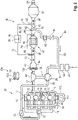
- FIG 1 shows the schematic representation of a diesel engine 10 with an intake tract 20 and an exhaust system 40.
- the diesel engine 10 is designed as a direct-injection diesel engine and has a plurality of combustion chambers 12.
- a fuel injector 14 for injecting a fuel into the respective combustion chamber 12 is arranged on each of the combustion chambers 12 .
- the diesel engine 10 is connected to an intake tract 20 at its inlet 16 and to an exhaust system 40 at its outlet 18 .
- the diesel engine 10 also includes a high-pressure exhaust gas recirculation system 90 with an exhaust gas recirculation line 96 in which a high-pressure exhaust gas recirculation valve 98 is arranged, via which an exhaust gas from the diesel engine 10 can be recirculated from the outlet 18 to the inlet 16.
- Inlet valves and outlet valves are arranged on the combustion chambers 12, with which a fluidic connection from the intake tract 20 to the combustion chambers 12 or from the combustion chambers 12 to the exhaust system 40 can be opened or closed.
- the intake tract 20 comprises an intake duct 28, in which, in the direction of flow of fresh air through the intake duct 28, is an air filter 22, downstream of the air filter 22 an air mass meter 24, in particular a hot-film air mass meter, downstream of the air mass meter 24 a compressor 26 of an exhaust gas turbocharger 36, downstream of the Compressor 26, a throttle valve 30 and further downstream an intercooler 32 are arranged.
- the air mass meter 24 can also be arranged in a filter housing of the air filter 22, so that the air filter 22 and the air mass meter 24 form an assembly.
- a junction 34 is provided downstream of the air filter 22 and upstream of the compressor 26 , at which junction an exhaust gas recirculation line 86 of a low-pressure exhaust gas recirculation system 80 opens into the intake passage 28 .
- the exhaust system 40 includes an exhaust gas duct 42 in which a turbine 44 of the exhaust gas turbocharger 36 is arranged in the flow direction of an exhaust gas of the diesel engine 10 through the first exhaust gas duct 42, which turbine drives the compressor 26 in the intake tract 20 via a shaft.
- the exhaust gas turbocharger 36 is preferably designed as an exhaust gas turbocharger 36 with variable turbine geometry.
- adjustable guide vanes are connected upstream of a turbine wheel of the turbine 44, via which the inflow of the exhaust gas onto the vanes of the turbine 44 can be varied.
- a plurality of exhaust gas aftertreatment components 46 , 48 , 50 , 52 , 54 , 94 are provided downstream of the turbine 44 .
- an oxidation catalytic converter 46 or an NO x storage catalytic converter 94 is arranged directly downstream of the turbine 44 as the first component of the exhaust gas aftertreatment.
- a first SCR catalytic converter 48 close to the engine preferably a particle filter 50 with a coating for the selective catalytic reduction of nitrogen oxides (SCR coating), is arranged downstream of the oxidation catalytic converter 46 or the NO x storage catalytic converter 94 .
- a second SCR catalytic converter 52 is arranged in the exhaust gas duct 42 downstream of the first SCR catalytic converter 48 close to the engine, preferably in the underbody position of a motor vehicle.
- the second SCR catalyst 52 includes an ammonia slip catalyst 54 .
- a first metering element 56 for metering a reducing agent 78 into the exhaust gas duct 42 is provided downstream of the oxidation catalytic converter 46 or of the NO x storage catalytic converter 94 and upstream of the first SCR catalytic converter 48 . Downstream of the first SCR catalytic converter 48, in particular downstream of the particle filter 50 with the SCR coating, an exhaust gas recirculation line 86 of a low-pressure exhaust gas recirculation system 80 branches off from the exhaust gas duct 42 at a junction 70 . A second metering element 58 is arranged downstream of the branch 70 and upstream of the second SCR catalytic converter 52 in order to meter the reducing agent 78 into the exhaust gas channel 42 .
- the first dosing element 56 and the second dosing element 58 are each connected via a reducing agent line 72, 74 to a common reducing agent tank 76 in which the reducing agent 78 is stored. Furthermore, the exhaust system 40 includes an exhaust gas flap 60 with which the exhaust gas recirculation via the low-pressure exhaust gas recirculation 80 can be controlled.
- the low-pressure exhaust gas recirculation system 80 includes an exhaust gas recirculation cooler 82 and an exhaust gas recirculation valve 84, via which the exhaust gas recirculation through the exhaust gas recirculation line 86 can be controlled.
- An exhaust gas temperature T EG can be detected in the exhaust gas duct 42 by a temperature sensor 38 or calculated by the engine control unit 100 in order to activate the low-pressure exhaust gas recirculation 80 as soon as the exhaust gas temperature T EG has exceeded a defined threshold value.
- a further temperature sensor can be provided on the exhaust gas recirculation line 86 of the low-pressure exhaust gas recirculation system 80 in order to determine the temperature of the recirculated exhaust gas downstream of the exhaust gas recirculation cooler 82 . This can prevent the recirculated exhaust gas from being cooled to such an extent that it falls below the dew point and water droplets condense out in the exhaust gas recirculation line 86 . It is thus possible to prevent water vapor or gas components contained in the exhaust gas from condensing out and causing damage or deposits in the low-pressure exhaust gas recirculation system 80 or in the intake tract 20 .
- a filter may also be provided downstream of the junction 70 and upstream of the EGR cooler 82 to minimize the entry of particulates into the low pressure EGR 80 .
- the exhaust gas recirculation duct 86 opens at a junction 34 into the intake duct 28 of the intake tract 20.
- An exhaust gas sensor 62 for detecting the ammonia concentration in the exhaust gas duct 42 is arranged in the exhaust system 40 downstream of the branch 70 for the low-pressure exhaust gas recirculation and upstream of the second dosing element 58 .
- the exhaust gas sensor 62 is preferably designed as an NH 3 sensor 88 or as an NH 3 -NO x combination sensor 92 .
- the particle filter 50 has a differential pressure sensor 64 with which a pressure difference ⁇ p across the particle filter 50 is determined. In this way, the loading condition of the particle filter 50 can be determined and regeneration of the particle filter 50 can be initiated if a defined loading level is exceeded.
- a temperature sensor 38 is provided in the exhaust system 40 in order to determine the exhaust gas temperature.
- a first exhaust gas mixer 66 can be provided downstream of the first dosing element 56 and upstream of the first SCR catalytic converter 48 in order to improve the mixing of the exhaust gas flow of the diesel engine 10 and reducing agent 78 before entry into the first SCR catalytic converter 48 and to shorten the length of the mixing section .
- a second exhaust gas mixer 68 can be arranged downstream of the second dosing element 58 and upstream of the second SCR catalytic converter 52 in order to mix the exhaust gas flow and the reducing agent 78 to improve and to support the evaporation of the reducing agent 78 in the exhaust gas channel 42.
- Diesel engine 10 is connected to an engine control unit 100, which is connected via signal lines (not shown) to exhaust gas sensor 62, 88, 92, differential pressure sensor 64, temperature sensor 38, and to fuel injectors 14 of diesel engine 10 and metering elements 56, 58.
- Engine control unit 100 has a computing unit 102 and a memory unit 104 in which a machine-readable program code 106 for carrying out a method according to the invention for treating the exhaust gas of diesel engine 10 is stored.
- FIG 2 An alternative exemplary embodiment of a diesel engine 10 according to the invention is shown. With essentially the same structure as to figure 1 executed, the differences from the previous embodiment will be discussed below.
- the diesel engine 10 shown also has in the exhaust system 40 an external heating means 108, in particular an electric heating element, with which an exhaust gas stream of the diesel engine 10 can be heated independently of the operating state of the diesel engine 10.
- the heating means 108 outside the engine is preferably arranged upstream of the oxidation catalytic converter 46 or the NOx storage catalytic converter 94 or is integrated into the oxidation catalytic converter 46 or the NOx storage catalytic converter 94 .
- the extra-engine heating means 108 can also be designed as an exhaust gas burner or as in figure 1 shown omitted.
- a switchable exhaust gas recirculation cooler 110 is arranged in the high-pressure exhaust gas recirculation 90 , which can be bridged by means of a bypass 112 .
- the exhaust gas flow recirculated through the high-pressure exhaust gas recirculation system 90 can thus be recirculated either cooled or uncooled.
- an exhaust gas recirculation cooler 110 can also be arranged in the high-pressure exhaust gas recirculation 90 , which cannot be bypassed and is always flowed through by the recirculated exhaust gas stream when the high-pressure exhaust gas recirculation valve 98 is opened.
- such an exhaust gas recirculation cooler 110 as in figure 1 shown, omitted.
- FIG 3 a flowchart for carrying out a method according to the invention for the exhaust aftertreatment of a diesel engine 10 is shown.
- a load state of diesel engine 10 and/or an exhaust gas temperature T EG is determined, with low load states correlating with low exhaust gas temperatures.
- the determined exhaust gas temperature T EG is compared with a first threshold temperature T S1 and/or the engine load P E is compared with a threshold load Ps.
- the reducing agent 78 is metered in exclusively through the first metering element 56 and exhaust gas recirculation occurs exclusively through the high-pressure exhaust gas recirculation system 90.
- the reducing agent 78 is metered in exclusively by the second metering element 58 and exhaust gas is recirculated both via the high-pressure exhaust gas recirculation 90 and via the low-pressure exhaust gas recirculation 80.
- a larger exhaust gas partial flow is preferably recirculated via the low-pressure exhaust gas recirculation 80 than via the high-pressure exhaust gas recirculation 90 .
Landscapes
- Engineering & Computer Science (AREA)
- Chemical & Material Sciences (AREA)
- Combustion & Propulsion (AREA)
- Mechanical Engineering (AREA)
- General Engineering & Computer Science (AREA)
- Chemical Kinetics & Catalysis (AREA)
- Health & Medical Sciences (AREA)
- Toxicology (AREA)
- Exhaust Gas After Treatment (AREA)
- Exhaust-Gas Circulating Devices (AREA)
Abstract
Description
- Die Erfindung betrifft ein Verfahren zur Abgasnachbehandlung eines Dieselmotors sowie einen Dieselmotor mit einem Abgasnachbehandlungssystem zur Durchführung eines solchen Verfahrens gemäß dem Oberbegriff der unabhängigen Patentansprüche.
- Die aktuelle und eine zukünftig immer schärfer werdende Abgasgesetzgebung stellt hohe Anforderungen an die motorischen Rohemissionen und die Abgasnachbehandlung von Verbrennungsmotoren. Dabei stellen die Forderungen nach einem weiter sinkenden Verbrauch und die weitere Verschärfung der Abgasnormen hinsichtlich der zulässigen Stickoxidemissionen Herausforderungen für die Motorenentwickler dar. Bei Ottomotoren erfolgt die Abgasreinigung in bekannter Weise über einen Drei-Wege-Katalysator sowie dem Drei-Wege-Katalysator vor- und nachgeschaltete weitere Katalysatoren. Bei Dieselmotoren finden aktuell Abgasnachbehandlungssysteme Verwendung, welche einen Oxidationskatalysator oder einen NOx-Speicherkatalysator, einen Katalysator zur selektiven katalytischen Reduktion von Stickoxiden (SCR-Katalysator) sowie einen Partikelfilter zur Abscheidung von Rußpartikeln und gegebenenfalls weitere Katalysatoren aufweisen. Um die hohen Anforderungen an minimale Stickoxidemissionen zu erfüllen, sind Abgasnachbehandlungssysteme bekannt, welche zwei in Reihe geschaltete SCR-Katalysatoren aufweisen, wobei jedem der SCR-Katalysatoren ein Dosierelement zur Eindosierung eines Reduktionsmittels vorgeschaltet ist. Als Reduktionsmittel wird dabei bevorzugt eine synthetische, wässrige Harnstofflösung verwendet, die in einer dem SCR-Katalysator vorgeschalteten Mischeinrichtung mit dem heißen Abgasstrom vermischt wird. Durch diese Vermischung wird die wässrige Harnstofflösung erhitzt, wodurch Ammoniak im Abgaskanal freigesetzt wird. Eine handelsübliche, wässrige Harnstofflösung setzt sich im Allgemeinen aus 32,5 % Harnstoff und 67,5 % Wasser zusammen.
- Um die Rohemissionen eines Verbrennungsmotors zu verringern, sind Abgasrückführungssysteme bekannt, bei welchen der Abgasstrom des Verbrennungsmotors, gegebenenfalls unter zusätzlicher Kühlung des Abgasstroms, zurückgeführt wird. Prinzipiell lässt sich dabei zwischen einer motornahen Hochdruckabgasrückführung und einer stromabwärts einer Turbine eines Abgasturboladers aus dem Abgaskanal abzweigenden Niederdruckabgasrückführung unterscheiden. Dabei wird das Abgas aus der Abgasanlage dem Ansaugtrakt des Verbrennungsmotors stromaufwärts eines Verdichters des Abgasturboladers zugeführt, um die NOx-Rohemissionen des Verbrennungsmotors zu verringern. Für die Freigabe der Niederdruckabgasrückführung muss eine bestimmte Temperaturschwelle überschritten werden, um eine Kondensatbildung am Abgasrückführungskühler beziehungsweise im Ansaugtrakt zu vermeiden. Bis zu der Freigabe der gekühlten Niederdruckabgasrückführung steht nur die in Bezug auf die Minderung der NOx-Rohemissionen weniger effiziente Hochdruckabgasrückführung zur Verfügung.
- Um die Effizienz des Abgasnachbehandlungssystems zur Reduzierung von Stickoxiden zu erhöhen sind Abgasnachbehandlungssysteme mit zwei in Reihe geschalteten SCR-Katalysatoren bekannt, wobei der erste SCR-Katalysator stromabwärts einer Turbine eines Abgasturboladers und stromaufwärts einer Verzweigung, an der die Niederdruck-Abgasrückführung aus dem Abgaskanal abzweigt, angeordnet ist. Der zweite SCR-Katalysator ist stromabwärts dieser Verzweigung angeordnet, um bei hohen Abgastemperaturen eine möglichst lange Abgaslauflänge und ein Abkühlen des Abgasstroms zu ermöglichen und somit auch bei hohen Motorleistungen eine effiziente Abgasnachbehandlung des Abgasstroms des Verbrennungsmotors zu ermöglichen.
- Aus der
DE 10 2019 105 748 A1 ist ein Verfahren zur Abgasnachbehandlung eines Verbrennungsmotors bekannt, welcher mit seinem Auslass mit einer Abgasanlage verbunden ist. Dabei sind in der Abgasanlage stromabwärts einer Turbine eines Abgasturboladers ein motornaher SCR-Katalysator, insbesondere ein Partikelfilter mit einer Beschichtung zur selektiven katalytischen Reduktion von Stickoxiden und stromabwärts des ersten SCR-Katalysators ein zweiter SCR-Katalysator angeordnet. Stromabwärts des ersten SCR-Katalysators und stromaufwärts des zweiten SCR-Katalysators ist ein Abgassensor zur Erfassung einer Ammoniakkonzentration im Abgaskanal angeordnet. Das Abgasnachbehandlungssystem umfasst ferner ein erstes Dosierelement mit welchem ein Reduktionsmittel stromaufwärts des ersten SCR-Katalysators in den Abgaskanal eindosierbar ist sowie ein zweites Dosierelement, mit welchem ein Reduktionsmittel stromabwärts des ersten SCR-Katalysators und stromaufwärts des zweiten SCR-Katalysators in den Abgaskanal eindosierbar ist. Dabei wird das Reduktionsmittel durch das erste Dosierelement in den Abgaskanal eindosiert und stromabwärts des ersten SCR-Katalysators eine Ammoniakkonzentration im Abgaskanal gemessen. Anhand der gemessenen Ammoniakkonzentration wird die Ammoniakbeladung des zweiten SCR-Katalysators und die Eindosierung des Reduktionsmittels durch das zweite Dosierelement geregelt. - Die
DE 10 2017 200 089 B3 beschreibt ein Verfahren zum Betrieb eines Kraftfahrzeugs mit einer ersten SCR-Abgasnachbehandlungseinrichtung stromaufwärts einer Abzweigung zu einer Niederdruck-Abgasrückführung. Das Kraftfahrzeug weist einen hybridelektrischen Antrieb auf, und stromabwärts der Abzweigung zu der Niederdruck-Abgasrückführung ist eine zweite SCR-Abgasnachbehandlungseinrichtung im Abgastrakt angeordnet. Ammoniak für die SCR-Abgasnachbehandlung wird stromaufwärts der Abzweigung zu der Niederdruck-Abgasrückführung zugeführt oder erzeugt. Im Fahrbetrieb wird laufend zumindest die aktuelle Ammoniak-Beladung der ersten SCR-Abgasnachbehandlungseinrichtung ermittelt und außerdem geprüft, ob die aktuelle Vortriebsanforderung für das Fahrzeug einer Kombination von Temperatur und Volumenstrom im Abgastrakt entspricht, die erwartungsgemäß zu Ammoniak-Desorption in der ersten SCR-Abgasnachbehandlungseinrichtung führt. Solange dies der Fall ist, wird die aktuelle Kombination von Drehmoment und Drehzahl des Verbrennungsmotors unter Nutzung des hybridelektrischen Antriebs zur Aufrechterhaltung der aktuellen Vortriebsanforderung so verändert, dass entweder die Betriebsbedingungen der ersten SCR-Abgasnachbehandlungseinrichtung unter den Desorptions-Grenzen bleiben oder die erste SCR-Abgasnachbehandlungseinrichtung beschleunigt Ammoniak desorbiert, wobei währenddessen von Niederdruck-Abgasrückführung auf Hochdruck-Abgasrückführung umgeschaltet wird. - Aus der
US 9 458 799 B2 - Die
US 8 833 059 B2 beschreibt einen Verbrennungsmotor mit einem Luftzufuhrsystem zur Zufuhr von Verbrennungsluft zum Verbrennungsmotor und einem Abgase des Verbrennungsmotors aufnehmenden Abgastrakt, in welchem ein Partikelfilter und eine zur selektiven katalytischen Stickoxidreduktion mittels Ammoniak befähigten SCR-Abgasreinigungskomponente angeordnet sind. Über eine Zugabevorrichtung kann Ammoniak oder ein zur Abspaltung von Ammoniak befähigtes Reduktionsmittel in den Abgastrakt stromauf der SCR-Abgasreinigungskomponente gegeben werden. Für den Verbrennungsmotor ist ein Abgasturbolader vorgesehen, dessen Turbine stromauf vom Partikelfilter im Abgastrakt angeordnet ist. Zur Rückführung von Abgas aus dem Abgastrakt in das Luftzufuhrsystem sind eine stromauf der Turbine des Abgasturboladers vom Abgastrakt abzweigende erste Abgasrückführleitung und eine stromab vom Partikelfilter vom Abgastrakt abzweigende zweite Abgasrückführleitung vorgesehen. - Nachteilig bei den aus dem Stand der Technik bekannten Lösungen ist es, dass es bei hochlastigen Betriebszuständen des Dieselmotors zu einer thermischen Desorption des im SCR-Katalysator eingespeicherten Ammoniaks kommen kann. Das dabei freigesetzte Ammoniak und dessen Reaktionsprodukte können in die Niederdruckabgasrückführung gelangen und sich dort ablagern, was zu Funktionsstörungen bis hin zum Ausfall der Niederdruckabgasrückführung führen kann.
- Der Erfindung liegt nun die Aufgabe zugrunde, bei einem Dieselmotor mit einem Abgasnachbehandlungssystem mit zwei in Reihe geschalteten SCR-Katalysatoren die Effizienz bezüglich der NOx-Konvertierung weiter zu verbessern und insbesondere die Gefahr von Ablagerungen in der Abgasanlage zu verringern.
- Erfindungsgemäß wird diese Aufgabe durch ein Verfahren zur Abgasnachbehandlung eines Dieselmotors, der mit seinem Auslass mit einer Abgasanlage verbunden ist, gelöst. In der Abgasanlage sind stromabwärts einer Turbine eines Abgasturboladers ein motornaher erster SCR-Katalysator und stromabwärts des motornahen ersten SCR-Katalysators ein zweiter SCR-Katalysator angeordnet. Die Abgasanlage umfasst ein erstes Dosierelement, mit welchem ein Reduktionsmittel stromaufwärts des ersten SCR-Katalysators in den Abgaskanal eindosierbar ist und ein zweites Dosierelement, mit welchem ein Reduktionsmittel stromabwärts des ersten SCR-Katalysators eindosierbar ist. Der Dieselmotor weist eine Hochdruckabgasrückführung, welche die Abgasanlage stromaufwärts der Turbine des Abgasturboladers mit einem Ansaugtrakt stromabwärts eines Verdichters des Abgasturboladers verbindet und eine Niederdruckabgasrückführung auf, welche stromabwärts des ersten SCR-Katalysators und stromaufwärts des zweiten Dosierelements aus einem Abgaskanal der Abgasanlage abzweigt. Der Dieselmotor beziehungsweise das Abgasnachbehandlungssystem des Dieselmotors weist ferner Mittel zur Bestimmung einer Motorlast des Dieselmotors, eines Abgasmassenstroms, einer Abgastemperatur und einer Schadstoffkonzentration in der Abgasanlage auf. Das erfindungsgemäße Verfahren umfasst folgende Schritte:
- Ermitteln eines Lastzustands des Dieselmotors und/oder einer Abgastemperatur des Dieselmotors,
- Vergleichen der Abgastemperatur mit einer ersten Schwellentemperatur und/oder der Motorlast mit einer Schwellenlast, wobei
- bei einer Abgastemperatur unterhalb der ersten Schwellentemperatur oder einer Motorlast unterhalb der Schwellenlast eine Eindosierung des Reduktionsmittels ausschließlich durch das erste Dosierelement erfolgt und eine Abgasrückführung über die Hochdruckabgasrückführung erfolgt, und wobei
- bei einer Abgastemperatur oberhalb der ersten Schwellentemperatur oder einer Motorlast oberhalb der Schwellenlast eine Eindosierung des Reduktionsmittels ausschließlich durch das zweite Dosierelement erfolgt und eine Abgasrückführung sowohl über die Hochdruckabgasrückführung als auch über die Niederdruckabgasrückführung erfolgt.
- Das erfindungsgemäße Verfahren ermöglicht zwei verschiedene Betriebsarten, bei denen in beiden Betriebsarten eine effiziente Konvertierung von Stickoxidemissionen sichergestellt wird und gleichzeitig betriebssicher Ablagerungen in der Abgasanlage, insbesondere in der Niederdruckabgasrückführung verhindert werden. Dadurch kann sichergestellt werden, dass das Abgasnachbehandlungssystem auch nach erhöhter Betriebsdauer eine effiziente Konvertierung von Stickoxiden ermöglicht.
- Durch die in den abhängigen Ansprüchen aufgeführten zusätzlichen Merkmale sind vorteilhafte Verbesserungen und Weiterentwicklungen des im unabhängigen Anspruch beschriebenen Verfahren möglich.
- In bevorzugter Ausgestaltung der Erfindung ist vorgesehen, dass bei einer Abgastemperatur oberhalb der ersten Schwellentemperatur oder einer Motorlast oberhalb der Schwellenlast mehr als 50% des zurückgeführten Gesamtabgasstroms über die Niederdruckabgasrückführung zurückgeführt wird. Durch eine Abgasrückführung über die Niederdruckabgasrückführung wird vergleichsweise kaltes Abgas in die Brennräume des Dieselmotors zurückgeführt, wodurch die Rohemissionen des Dieselmotors verringert werden können. Dies ermöglicht einen geringeren Aufwand bei der Abgasnachbehandlung und somit einen geringeren Einsatz von Reduktionsmittel, wodurch die Gefahr von Ablagerungen weiter reduziert wird.
- In weiterer bevorzugter Ausgestaltung der Erfindung ist vorgesehen, dass der über die Niederdruckabgasrückführung zurückgeführte Abgasstrom durch einen Abgasrückführungskühler abgekühlt wird. Durch eine zusätzliche Kühlung des über die Niederdruckabgasrückführung zurückgeführten Abgasstroms können die Rohemissionen des Dieselmotors besonders effizient abgesenkt werden.
- In einer vorteilhaften Ausgestaltung des Verfahrens ist vorgesehen, dass ein Abgasstrom des Dieselmotors durch ein außermotorisches Heizmittel vor dem Eintritt in den ersten SCR-Katalysator beheizt wird. Außermotorische Heizmittel können insbesondere elektrische Heizelemente oder Abgasbrenner sein, mit welchen der Abgasstrom im Wesentlichen unabhängig vom Betriebszustand des Dieselmotors erhitzt werden kann. Durch ein Beheizen des Abgasstroms können die Abgasnachbehandlungskomponenten nach einem Kaltstart des Dieselmotors schneller auf ihre jeweilige Betriebstemperatur aufgeheizt werden, sodass die Konvertierung von Schadstoffen, insbesondere von Stickoxiden, in der Kaltstartphase verbessert wird.
- Besonders bevorzugt ist dabei, wenn der Abgasstrom des Verbrennungsmotors durch das außermotorische Heizmittel beheizt wird, wenn die Abgastemperatur unterhalb eines zweiten Schwellenwertes liegt oder die Temperatur einer Abgasnachbehandlungskomponente unterhalb einer Light-Off-Temperatur der jeweiligen Abgasnachbehandlungskomponente liegt.
- In einer vorteilhaften Weiterentwicklung des Verfahrens ist vorgesehen, dass bei niedrigen Motorlasten und/oder niedrigen Abgastemperaturen eine ungekühlte Abgasrückführung des über die Hochdruckabgasrückführung zurückgeführten Abgasstroms und bei hohen Motorlasten eine gekühlte Abgasrückführung des über die Hochdruckabgasrückführung zurückgeführten Abgasstroms erfolgt. Dadurch ist eine besonders effiziente Verringerung der Rohemissionen des Dieselmotors möglich.
- In einer weiteren Verbesserung des Verfahrens ist vorgesehen, dass ein Abgasrückführungsventil der Niederdruckabgasrückführung geschlossen wird, wenn eine Eindosierung von Reduktionsmittel durch das erste Dosierelement erfolgt und stromabwärts des ersten SCR-Katalysators ein Anstieg einer Ammoniakkonzentration im Abgasstrom des Dieselmotors detektiert wird. Durch ein Schließen des Abgasrückführungsventils kann ein Abgasstrom durch die Niederdruckabgasrückführung verhindert werden. Somit wird sichergestellt, dass es zu keiner Versottung und/oder zu Ablagerungen von Reduktionsmittel oder Reaktionsprodukten des Reduktionsmittels in der Niederdruckabgasrückführung kommt. Ein weiterer Teilaspekt betrifft einen Dieselmotor mit einem Ansaugtrakt und einer Abgasanlage, wobei der Dieselmotor mit seinem Auslass mit einer Abgasanlage verbunden ist.
- In der Abgasanlage sind stromabwärts einer Turbine eines Abgasturboladers ein motornaher erster SCR-Katalysator und stromabwärts des motornahen ersten SCR-Katalysators ein zweiter SCR-Katalysator angeordnet. Die Abgasanlage umfasst ein erstes Dosierelement, mit welchem ein Reduktionsmittel stromaufwärts des ersten SCR-Katalysators in den Abgaskanal eindosierbar ist und ein zweites Dosierelement, mit welchem ein Reduktionsmittel stromabwärts des ersten SCR-Katalysators eindosierbar ist. Der Dieselmotor weist eine Hochdruckabgasrückführung, welche die Abgasanlage stromaufwärts der Turbine des Abgasturboladers mit einem Ansaugtrakt stromabwärts eines Verdichters des Abgasturboladers verbindet und eine Niederdruckabgasrückführung auf, welche stromabwärts des ersten SCR-Katalysators und stromaufwärts des zweiten Dosierelements aus einem Abgaskanal der Abgasanlage abzweigt. Der Dieselmotor beziehungsweise das Abgasnachbehandlungssystem des Dieselmotors weist ferner Mittel zur Bestimmung einer Motorlast des Dieselmotors, eines Abgasmassenstroms, einer Abgastemperatur und einer Schadstoffkonzentration in der Abgasanlage auf. Der Dieselmotor umfasst ferner ein Motorsteuergerät mit einer Recheneinheit und einer Speichereinheit, welches dazu eingerichtet ist, ein solches Verfahren zur Abgasnachbehandlung eines Dieselmotors auszuführen, wenn ein in der Speichereinheit abgelegter Programmcode durch die Recheneinheit des Motorsteuergeräts ausgeführt wird.
- Durch einen solchen Dieselmotor können die aus dem Stand der Technik bekannten Nachteile bezüglich ansteigender Stickoxidemissionen bei hohen Abgastemperaturen und Ablagerungen in der Abgasanlage, insbesondere in der Niederdruckabgasrückführung, betriebssicher verhindert werden.
- In einer vorteilhaften Ausgestaltung des Dieselmotors ist vorgesehen, dass in der Abgasanlage ein Abgassensor angeordnet ist, wobei der Abgassensor als NH3-Sensor oder als NH3-NOx-Kombisensor ausgeführt ist. Durch einen NH3-Sensor oder einen NH3-NOx-Kombisensor kann auf einfache Art und Weise ein Ammoniakdurchbruch durch den ersten SCR-Katalysator detektiert werden, wobei mit einem solchen Ammoniakdurchbruch die Gefahr von Ablagerungen in der Abgasanlage steigt.
- In einer bevorzugten Ausführungsform des Dieselmotors ist vorgesehen, dass die Hochdruckabgasrückführung einen schaltbaren Abgasrückführungskühler mit einem Bypass aufweist, wobei ein über die Hochdruckabgasrückführung des Dieselmotors zurückgeführter Abgasstrom in einem ersten Betriebszustand des Dieselmotors durch den Abgasrückführungskühler geleitet und abgekühlt wird und in einem zweiten Betriebszustand durch den Bypass geleitet und ungekühlt zurückgeführt wird. Durch eine wahlweise gekühlte oder ungekühlte Abgasrückführung über die Hochdruckabgasrückführung ist eine besonders effiziente Minderung der Rohemissionen des Dieselmotors möglich.
- Die verschiedenen in dieser Anmeldung genannten Ausführungsformen der Erfindung sind, sofern im Einzelfall nicht anders ausgeführt, mit Vorteil miteinander kombinierbar.
- Die Erfindung wird nachfolgend in Ausführungsbeispielen anhand der zugehörigen Zeichnungen erläutert. Gleiche Bauteile oder Bauteile mit gleicher Funktion sind dabei in den unterschiedlichen Figuren mit denselben Bezugsziffern gekennzeichnet. Es zeigen:
- Figur 1
- ein bevorzugtes Ausführungsbeispiel für einen erfindungsgemäßen Dieselmotor mit einem Abgasnachbehandlungssystem;
- Figur 2
- ein weiteres bevorzugtes Ausführungsbeispiel für einen erfindungsgemäßen Dieselmotor mit einem Abgasnachbehandlungssystem; und
- Figur 3
- ein Ablaufdiagramm zur Durchführung eines erfindungsgemäßen Verfahrens zur Abgasnachbehandlung eines Dieselmotors.
-
Figur 1 zeigt die schematische Darstellung eines Dieselmotors 10 mit einem Ansaugtrakt 20 und einer Abgasanlage 40. Der Dieselmotor 10 ist als ein direkteinspritzender Dieselmotor ausgeführt und weist mehrere Brennräume 12 auf. An den Brennräumen 12 ist jeweils ein Kraftstoffinjektor 14 zur Einspritzung eines Kraftstoffes in den jeweiligen Brennraum 12 angeordnet. Der Dieselmotor 10 ist mit seinem Einlass 16 mit einem Ansaugtrakt 20 und mit seinem Auslass 18 mit einer Abgasanlage 40 verbunden. Der Dieselmotor 10 umfasst ferner eine Hochdruck-Abgasrückführung 90 mit einer Abgasrückführungsleitung 96, in welcher ein Hochdruck-Abgasrückführungsventil 98 angeordnet ist, über welches ein Abgas des Dieselmotors 10 von dem Auslass 18 zum Einlass 16 zurückgeführt werden kann. An den Brennräumen 12 sind Einlassventile und Auslassventile angeordnet, mit welchen eine fluidische Verbindung vom Ansaugtrakt 20 zu den Brennräumen 12 oder von den Brennräumen 12 zur Abgasanlage 40 geöffnet oder verschlossen werden kann. - Der Ansaugtrakt 20 umfasst einen Ansaugkanal 28, in welchem in Strömungsrichtung von Frischluft durch den Ansaugkanal 28 ein Luftfilter 22, stromabwärts des Luftfilters 22 ein Luftmassenmesser 24, insbesondere ein Heißfilmluftmassenmesser, stromabwärts des Luftmassenmessers 24 ein Verdichter 26 eines Abgasturboladers 36, stromabwärts des Verdichters 26 eine Drosselklappe 30 und weiter stromabwärts ein Ladeluftkühler 32 angeordnet sind. Dabei kann der Luftmassenmesser 24 auch in einem Filtergehäuse des Luftfilters 22 angeordnet sein, sodass der Luftfilter 22 und der Luftmassenmesser 24 eine Baugruppe ausbildet. Stromabwärts des Luftfilters 22 und stromaufwärts des Verdichters 26 ist eine Einmündung 34 vorgesehen, an welcher eine Abgasrückführungsleitung 86 einer Niederdruck-Abgasrückführung 80 in den Ansaugkanal 28 mündet.
- Die Abgasanlage 40 umfasst einen Abgaskanal 42, in welchem in Strömungsrichtung eines Abgases des Dieselmotors 10 durch den ersten Abgaskanal 42 eine Turbine 44 des Abgasturboladers 36 angeordnet ist, welche den Verdichter 26 im Ansaugtrakt 20 über eine Welle antreibt. Der Abgasturbolader 36 ist vorzugsweise als Abgasturbolader 36 mit variabler Turbinengeometrie ausgeführt. Dazu sind einem Turbinenrad der Turbine 44 verstellbare Leitschaufeln vorgeschaltet, über welche die Anströmung des Abgases auf die Schaufeln der Turbine 44 variiert werden kann. Stromabwärts der Turbine 44 sind mehrere Abgasnachbehandlungskomponenten 46, 48, 50, 52, 54, 94 vorgesehen. Dabei ist unmittelbar stromabwärts der Turbine 44 als erste Komponente der Abgasnachbehandlung ein Oxidationskatalysator 46 oder ein NOx-Speicherkatalysator 94 angeordnet. Stromabwärts des Oxidationskatalysators 46 oder des NOx-Speicherkatalysators 94 ist ein motornaher erster SCR-Katalysator 48, vorzugsweise ein Partikelfilter 50 mit einer Beschichtung zur selektiven katalytischen Reduktion von Stickoxiden (SCR-Beschichtung) angeordnet. Stromabwärts des motornahen ersten SCR-Katalysators 48 ist vorzugsweise in Unterbodenlage eines Kraftfahrzeuges ein zweiter SCR-Katalysator 52 im Abgaskanal 42 angeordnet. Der zweite SCR-Katalysator 52 weist einen Ammoniak-Sperrkatalysator 54 auf. Stromabwärts des Oxidationskatalysators 46 oder des NOx-Speicherkatalysators 94 und stromaufwärts des ersten SCR-Katalysators 48 ist ein erstes Dosierelement 56 zur Eindosierung eines Reduktionsmittels 78 in den Abgaskanal 42 vorgesehen. Stromabwärts des ersten SCR-Katalysators 48, insbesondere stromabwärts des Partikelfilters 50 mit der SCR-Beschichtung, zweigt an einer Verzweigung 70 eine Abgasrückführungsleitung 86 einer Niederdruck-Abgasrückführung 80 aus dem Abgaskanal 42 ab. Stromabwärts der Verzweigung 70 und stromaufwärts des zweiten SCR-Katalysators 52 ist ein zweites Dosierelement 58 angeordnet, um das Reduktionsmittel 78 in den Abgaskanal 42 einzudosieren. Das erste Dosierelement 56 und das zweite Dosierelement 58 sind jeweils über eine Reduktionsmittelleitung 72, 74 mit einem gemeinsamen Reduktionsmittelbehälter 76 verbunden, in welchem das Reduktionsmittel 78 bevorratet ist. Ferner umfasst die Abgasanlage 40 eine Abgasklappe 60, mit welcher die Abgasrückführung über die Niederdruck-Abgasrückführung 80 gesteuert werden kann.
- Die Niederdruck-Abgasrückführung 80 umfasst neben der Abgasrückführungsleitung 86 einen Abgasrückführungskühler 82 und ein Abgasrückführungsventil 84, über welches die Abgasrückführung durch die Abgasrückführungsleitung 86 steuerbar ist. In dem Abgaskanal 42 kann eine Abgastemperatur TEG durch einen Temperatursensor 38 erfasst werden oder durch das Motorsteuergerät 100 berechnet werden, um die Niederdruck-Abgasrückführung 80 zu aktivieren, sobald die Abgastemperatur TEG einen definierten Schwellenwert überschritten hat. An der Abgasrückführungsleitung 86 der Niederdruck-Abgasrückführung 80 kann ein weiterer Temperatursensor vorgesehen werden, um die Temperatur des zurückgeführten Abgases stromabwärts des Abgasrückführungskühlers 82 zu ermitteln. Dadurch kann vermieden werden, dass das zurückgeführte Abgas so stark gekühlt wird, dass der Taupunkt unterschritten wird und es zu einem Auskondensieren von Wassertropfen in der Abgasrückführungsleitung 86 kommt. Somit kann verhindert werden, dass Wasserdampf oder im Abgas enthaltene Gaskomponenten auskondensieren und in der Niederdruck-Abgasrückführung 80 oder im Ansaugtrakt 20 zu Beschädigungen oder Ablagerungen führen. Stromabwärts der Verzweigung 70 und stromaufwärts des Abgasrückführungskühlers 82 kann ferner ein Filter vorgesehen werden, um den Eintrag von Partikeln in die Niederdruck-Abgasrückführung 80 zu minimieren. Der Abgasrückführungskanal 86 mündet an einer Einmündung 34 in den Ansaugkanal 28 des Ansaugtraktes 20.
- In der Abgasanlage 40 ist stromabwärts der Verzweigung 70 für die Niederdruck-Abgasrückführung und stromaufwärts des zweiten Dosierelements 58 ein Abgassensor 62 zur Erfassung der Ammoniak-Konzentration im Abgaskanal 42 angeordnet. Der Abgassensor 62 ist vorzugsweise als NH3-Sensor 88 oder als NH3-NOx-Kombisensor 92 ausgeführt. Ferner weist der Partikelfilter 50 einen Differenzdrucksensor 64 auf, mit welchem eine Druckdifferenz Δp über den Partikelfilter 50 ermittelt wird. Auf diese Weise kann der Beladungszustand des Partikelfilters 50 ermittelt und bei Überschreiten eines definierten Beladungsniveaus eine Regeneration des Partikelfilters 50 eingeleitet werden. Ferner ist in der Abgasanlage 40 ein Temperatursensor 38 vorgesehen, um die Abgastemperatur zu ermitteln.
- Stromabwärts des ersten Dosierelements 56 und stromaufwärts des ersten SCR-Katalysators 48 kann ein erster Abgasmischer 66 vorgesehen sein, um eine Durchmischung von Abgasstrom des Dieselmotors 10 und Reduktionsmittel 78 vor Eintritt in den ersten SCR-Katalysator 48 zu verbessern und die Länge der Mischstrecke zu verkürzen. Stromabwärts des zweiten Dosierelements 58 und stromaufwärts des zweiten SCR-Katalysators 52 kann ein zweiter Abgasmischer 68 angeordnet sein, um die Vermischung von Abgasstrom und Reduktionsmittel 78 zu verbessern und das Verdampfen des Reduktionsmittels 78 im Abgaskanal 42 zu unterstützen.
- Der Dieselmotor 10 ist mit einem Motorsteuergerät 100 verbunden, welches über nicht dargestellte Signalleitungen mit dem Abgassensor 62, 88, 92, dem Differenzdrucksensor 64, dem Temperatursensor 38 sowie mit den Kraftstoffinjektoren 14 des Dieselmotors 10 und den Dosierelementen 56, 58 verbunden ist. Das Motorsteuergerät 100 weist eine Recheneinheit 102 und eine Speichereinheit 104 auf, in welcher ein maschinenlesbarer Programmcode 106 zur Durchführung eines erfindungsgemäßen Verfahrens zur Abgasnachbehandlung des Dieselmotors 10 gespeichert ist.
- In
Figur 2 ist ein alternatives Ausführungsbeispiel eines erfindungsgemäßen Dieselmotors 10 dargestellt. Bei im Wesentlichen gleichen Aufbau wie zuFigur 1 ausgeführt, wird im Folgenden auf die Unterschiede zu der vorhergehenden Ausführungsform eingegangen. Der inFigur 2 dargestellte Dieselmotor 10 weist in der Abgasanlage 40 zusätzlich ein außermotorisches Heizmittel 108, insbesondere ein elektrisches Heizelement, auf, mit welchem ein Abgasstrom des Dieselmotors 10 unabhängig vom Betriebszustand des Dieselmotors 10 aufgeheizt werden kann. Das außermotorische Heizmittel 108 ist vorzugsweise stromaufwärts des Oxidationskatalysators 46 oder des NOx-Speicherkatalysators 94 angeordnet oder in den Oxidationskatalysator 46 oder den NOx-Speicherkatalysator 94 integriert. Alternativ kann das außermotorische Heizmittel 108 auch als ein Abgasbrenner ausgebildet sein oder wie inFigur 1 dargestellt entfallen. - Ferner ist in der Hochdruckabgasrückführung 90 ein schaltbarer Abgasrückführungskühler 110 angeordnet, welcher mittels eines Bypasses 112 überbrückt werden kann. Somit kann der durch die Hochdruckabgasrückführung 90 zurückgeführte Abgasstrom wahlweise gekühlt oder ungekühlt zurückgeführt werden. Alternativ kann in der Hochdruckabgasrückführung 90 auch ein Abgasrückführungskühler 110 angeordnet sein, welcher nicht überbrückt werden kann und bei Öffnung des Hochdruckabgasrückführungsventils 98 stets vom zurückgeführten Abgasstrom durchströmt wird. Alternativ kann ein solcher Abgasrückführungskühler 110 auch, wie in
Figur 1 dargestellt, entfallen. - In
Figur 3 ist ein Ablaufdiagramm zur Durchführung eines erfindungsgemäßen Verfahrens zur Abgasnachbehandlung eines Dieselmotors 10 dargestellt. In einem ersten Verfahrensschritt <100> wir ein Lastzustand des Dieselmotors 10 und/oder eine Abgastemperatur TEG ermittelt, wobei niedrige Lastzustände mit niedrigen Abgastemperaturen korrelieren. In einem Verfahrensschritt <110> wird die ermittelte Abgastemperatur TEG mit einer ersten Schwellentemperatur TS1 und/oder die Motorlast PE mit einer Schwellenlast Ps verglichen. Bei einer Abgastemperatur TEG unterhalb der ersten Schwellentemperatur TS1 oder einer Motorlast PE unterhalb der Schwellenlast Ps in einem Verfahrensschritt <120> erfolgt eine Eindosierung des Reduktionsmittels 78 ausschließlich durch das erste Dosierelement 56 und eine Abgasrückführung ausschließlich durch die Hochdruckabgasrückführung 90. Bei einer Abgastemperatur TEG oberhalb der ersten Schwellentemperatur TS1 oder einer Motorlast PE oberhalb der Schwellenlast Ps erfolgt in einem Verfahrensschritt <130> eine Eindosierung des Reduktionsmittels 78 ausschließlich durch das zweite Dosierelement 58 und eine Abgasrückführung sowohl über die Hochdruckabgasrückführung 90 als auch über die Niederdruck-Abgasrückführung 80. Dabei wird vorzugsweise ein größerer Abgasteilstrom über die Niederdruck-Abgasrückführung 80 als über die Hochdruck-Abgasrückführung 90 zurückgeführt. -
- 10
- Verbrennungsmotor / Dieselmotor
- 12
- Brennraum
- 14
- Kraftstoffinjektor
- 16
- Einlass
- 18
- Auslass
- 20
- Ansaugtrakt
- 22
- Luftfilter
- 24
- Luftmassenmesser
- 26
- Verdichter
- 28
- Ansaugkanal
- 30
- Drosselklappe
- 32
- Ladeluftkühler
- 34
- Einmündung
- 36
- Abgasturbolader
- 38
- Temperatursensor
- 40
- Abgasanlage
- 42
- Abgaskanal
- 44
- Turbine
- 46
- Oxidationskatalysator
- 48
- erster SCR-Katalysator
- 50
- Partikelfilter mit SCR-Beschichtung
- 52
- zweiter SCR-Katalysator
- 54
- Ammoniak-Sperrkatalysator
- 56
- erstes Dosierelement
- 58
- zweites Dosierelement
- 60
- Abgasklappe
- 62
- Abgassensor
- 64
- Differenzdrucksensor
- 66
- erster Abgasmischer
- 68
- zweiter Abgasmischer
- 70
- Verzweigung
- 72
- erste Reduktionsmittelleitung
- 74
- zweite Reduktionsmittelleitung
- 76
- Reduktionsmittelbehälter
- 78
- Reduktionsmittel
- 80
- Niederdruck-Abgasrückführung
- 82
- Abgasrückführungskühler
- 84
- Abgasrückführungsventil
- 86
- Abgasrückführungsleitung
- 88
- NH3-Sensor
- 90
- Hochdruck-Abgasrückführung
- 92
- NH3-NOx-Kombisensor
- 94
- NOx-Speicherkatalysator
- 96
- Abgasrückführungsleitung
- 98
- Hochdruck-Abgasrückführungsventil
- 100
- Motorsteuergerät
- 102
- Recheneinheit
- 104
- Speichereinheit
- 106
- Programmcode
- 108
- außermotorisches Heizmittel / elektrisches Heizelement
- 110
- Abgasrückführungskühler
- 112
- Bypass
Claims (10)
- Verfahren zur Abgasnachbehandlung eines Dieselmotors (10), der mit seinem Auslass (18) mit einer Abgasanlage (40) verbunden ist, wobei in der Abgasanlage (40) stromabwärts einer Turbine (44) eines Abgasturboladers (36) ein motornaher erster SCR-Katalysator (48, 50) und stromabwärts des motornahen ersten SCR-Katalysators (48, 50) ein zweiter SCR-Katalysator (52) angeordnet sind, sowie mit einem ersten Dosierelement (56), mit welchem ein Reduktionsmittel (78) stromaufwärts des ersten SCR-Katalysators (48, 50) in den Abgaskanal (42) eindosierbar ist und mit einem zweiten Dosierelement (58), mit welchem ein Reduktionsmittel (78) stromabwärts des ersten SCR-Katalysators (48, 50) in den Abgaskanal (42) eindosierbar ist, wobei der Dieselmotor (10) eine Hochdruck-Abgasrückführung (90), welche die Abgasanlage (40) stromaufwärts der Turbine (44) des Abgasturboladers (36) mit einem Ansaugtrakt (20) stromabwärts eines Verdichters (26) des Abgasturboladers (36) verbindet, umfasst und eine Niederdruck-Abgasrückführung (80) aufweist, welche stromabwärts des ersten SCR-Katalysators (48, 50) und stromaufwärts des zweiten Dosierelements (58) aus einem Abgaskanal (42) der Abgasanlage (40) abzweigt, sowie mit Mitteln (38, 62, 88, 92, 94, 100) zur Bestimmung einer Motorlast des Dieselmotors (10), eines Abgasmassenstroms, einer Abgastemperatur (TEG) und einer Schadstoffkonzentration in der Abgasanlage (40), wobei das Verfahren folgende Schritte umfasst:- Ermitteln eines Lastzustands des Dieselmotors (10) und/oder einer Abgastemperatur (TEG) des Dieselmotors (10),- Vergleichen der Abgastemperatur (TEG) mit einer ersten Schwellentemperatur (TS1) und/oder der Motorlast (PE) mit einer Schwellenlast (PS), wobei- bei einer Abgastemperatur (TEG) unterhalb der ersten Schwellentemperatur (TS1) oder einer Motorlast (PE) unterhalb der Schwellenlast (Ps) eine Eindosierung des Reduktionsmittels (78) ausschließlich durch das erste Dosierelement (56) erfolgt und eine Abgasrückführung über die Hochdruck-Abgasrückführung (90) erfolgt, und wobei- bei einer Abgastemperatur (TEG) oberhalb der ersten Schwellentemperatur (TS1) oder einer Motorlast (PE) oberhalb der Schwellenlast (Ps) eine Eindosierung des Reduktionsmittels (78) ausschließlich durch das zweite Dosierelement (58) erfolgt und eine Abgasrückführung sowohl über die Hochdruck-Abgasrückführung (90) als auch über die Niederdruck-Abgasrückführung (80) erfolgt.
- Verfahren nach Anspruch 1, dadurch gekennzeichnet, dass bei einer Abgastemperatur (TEG) oberhalb der ersten Schwellentemperatur (TS1) oder einer Motorlast (PE) oberhalb der Schwellenlast (PS) mehr als 50% der zurückgeführten Gesamtabgasstroms über die Niederdruckabgasrückführung zurückgeführt wird.
- Verfahren nach Anspruch 1 oder 2, dadurch gekennzeichnet, dass der über die Niederdruck-Abgasrückführung (80) zurückgeführte Abgasstrom durch einen Abgasrückführungskühler (82) abgekühlt wird.
- Verfahren nach einem der Ansprüche 1 bis 3, dadurch gekennzeichnet, dass ein Abgasstrom des Dieselmotors (10) durch ein außermotorisches Heizmittel (108) vor Eintritt in den ersten SCR-Katalysator beheizt wird.
- Verfahren nach Anspruch 4, dadurch gekennzeichnet, dass der Abgasstrom des Dieselmotors (10) durch das außermotorische Heizmittel (108) beheizt wird, wenn die Abgastemperatur (TEG) unterhalb einer zweiten Schwellentemperatur (TS2) liegt oder die Temperatur einer Abgasnachbehandlungskomponente (46, 48, 50, 52, 94) unterhalb einer Light-Off-Temperatur der jeweiligen Abgasnachbehandlungskomponente (46, 48, 50, 52, 94) liegt.
- Verfahren nach einem der Ansprüche 1 bis 5, dadurch gekennzeichnet, dass bei niedrigen Motorlasten eine ungekühlte Abgasrückführung des über die Hochdruck-Abgasrückführung (90) zurückgeführten Abgasstroms und bei hohen Motorlasten eine gekühlte Abgasrückführung des über die Hochdruck-Abgasrückführung (90) zurückgeführten Abgasstroms erfolgt.
- Verfahren nach einem der Ansprüche 1 bis 6, dadurch gekennzeichnet, dass ein Abgasrückführungsventil (84) der Niederdruck-Abgasrückführung (80) geschlossen wird, wenn eine Eindosierung von Reduktionsmittel (78) durch das erste Dosierelement (56) erfolgt und stromabwärts des ersten SCR-Katalysators (48, 50) ein Anstieg einer Ammoniakkonzentration im Abgasstrom des Dieselmotors (10) detektiert wird.
- Dieselmotor (10) mit einem Ansaugtrakt (20) und einer Abgasanlage (40), wobei der Dieselmotor (10) mit seinem Auslass (18) mit der Abgasanlage (40) verbunden ist, wobei in der Abgasanlage (40) stromabwärts einer Turbine (44) eines Abgasturboladers (36) ein motornaher erster SCR-Katalysator (48, 50) und stromabwärts des motornahen ersten SCR-Katalysators (48, 50) ein zweiter SCR-Katalysator (52) angeordnet sind, sowie mit einem ersten Dosierelement (56), mit welchem ein Reduktionsmittel (78) stromaufwärts des ersten SCR-Katalysators (48, 50) in den Abgaskanal (42) eindosierbar ist und mit einem zweiten Dosierelement (58), mit welchem ein Reduktionsmittel (78) stromabwärts des ersten SCR-Katalysators (48, 50) eindosierbar ist, wobei der Dieselmotor (10) eine Hochdruck-Abgasrückführung (90), welche die Abgasanlage (40) stromaufwärts der Turbine (44) des Abgasturboladers (36) mit dem Ansaugtrakt (20) stromabwärts eines Verdichters (26) des Abgasturboladers (36) verbindet und eine Niederdruck-Abgasrückführung (80) aufweist, welche stromabwärts des ersten SCR-Katalysators (48, 50) und stromaufwärts des zweiten Dosierelements (58) aus einem Abgaskanal (42) der Abgasanlage (40) abzweigt, sowie mit Mitteln (38, 62, 88, 92, 94, 100) zur Bestimmung einer Motorlast des Dieselmotors (10), eines Abgasmassenstroms, einer Abgastemperatur (TEG) und einer Schadstoffkonzentration in der Abgasanlage (40), sowie mit einem Motorsteuergerät (100) mit einer Recheneinheit (102) und einer Speichereinheit (104), wobei das Motorsteuergerät (100) ein Verfahren nach einem der Ansprüche 1 bis 7 ausführt, wenn ein in der Speichereinheit (104) abgelegter Programmcode (106) durch die Recheneinheit (102) des Motorsteuergeräts (100) ausgeführt wird.
- Dieselmotor (10) nach Anspruch 8, dadurch gekennzeichnet, dass in der Abgasanlage (40) ein Abgassensor (62) angeordnet ist, wobei der Abgassensor (62) als NH3-Sensor (88) oder als NH3-NOx-Kombisensor (92) ausgeführt ist.
- Dieselmotor (10) nach Anspruch 8 oder 9, dadurch gekennzeichnet, dass die Hochdruck-Abgasrückführung (90) einen schaltbaren Abgasrückführungskühler (110) mit einem Bypass (112) aufweist, wobei ein über die Hochdruck-Abgasrückführung des Dieselmotors (10) zurückgeführter Abgasstrom in einem ersten Betriebszustand durch den Abgasrückführungskühler (110) geleitet und abgekühlt wird und in einem zweiten Betriebszustand durch den Bypass (112) geleitet und ungekühlt zurückgeführt wird.
Applications Claiming Priority (1)
| Application Number | Priority Date | Filing Date | Title |
|---|---|---|---|
| DE102021203710.0A DE102021203710A1 (de) | 2021-04-14 | 2021-04-14 | Verfahren zur Abgasnachbehandlung eines Dieselmotors und Dieselmotor |
Publications (2)
| Publication Number | Publication Date |
|---|---|
| EP4074946A1 true EP4074946A1 (de) | 2022-10-19 |
| EP4074946B1 EP4074946B1 (de) | 2024-01-03 |
Family
ID=80953331
Family Applications (1)
| Application Number | Title | Priority Date | Filing Date |
|---|---|---|---|
| EP22157094.8A Active EP4074946B1 (de) | 2021-04-14 | 2022-02-16 | Verfahren zur abgasnachbehandlung eines dieselmotors und dieselmotor |
Country Status (2)
| Country | Link |
|---|---|
| EP (1) | EP4074946B1 (de) |
| DE (1) | DE102021203710A1 (de) |
Citations (8)
| Publication number | Priority date | Publication date | Assignee | Title |
|---|---|---|---|---|
| EP2511492A1 (de) * | 2009-12-08 | 2012-10-17 | Toyota Jidosha Kabushiki Kaisha | Abgasemissionssteuerungssystem für einen verbrennungsmotor |
| US20130145831A1 (en) * | 2011-12-09 | 2013-06-13 | Kia Motors Corporation | System and method for monitoring exhaust gas recirculation |
| US8833059B2 (en) | 2010-11-04 | 2014-09-16 | Daimler Ag | Motor-vehicle internal combustion engine with exhaust-gas recirculation |
| US9458799B2 (en) | 2010-11-04 | 2016-10-04 | Daimler Ag | Method for operating motor vehicle internal combustion engine |
| DE102017200089B3 (de) | 2017-01-05 | 2018-06-07 | Ford Global Technologies, Llc | Kraftfahrzeug mit Abgasturbolader und SCR-Abgasnachbehandlung sowie Verfahren zu dessen Betrieb |
| DE102018102490A1 (de) * | 2017-03-08 | 2018-09-13 | Volkswagen Aktiengesellschaft | Vorrichtung und Verfahren zur Abgasnachbehandlung eines Verbrennungsmotors |
| US20190211728A1 (en) * | 2018-01-11 | 2019-07-11 | Ford Global Technologies, Llc | Methods and systems for exhaust gas recirculation |
| DE102019105748A1 (de) | 2019-03-07 | 2020-09-10 | Volkswagen Aktiengesellschaft | Verfahren zur Abgasnachbehandlung eines Verbrennungsmotors sowie Abgasnachbehandlungssystem |
Family Cites Families (1)
| Publication number | Priority date | Publication date | Assignee | Title |
|---|---|---|---|---|
| DE102011120326A1 (de) | 2011-07-25 | 2013-01-31 | Volkswagen Aktiengesellschaft | Brennkraftmaschine und Verfahren zumBetrieb einer Brennkraftmaschine |
-
2021
- 2021-04-14 DE DE102021203710.0A patent/DE102021203710A1/de active Pending
-
2022
- 2022-02-16 EP EP22157094.8A patent/EP4074946B1/de active Active
Patent Citations (8)
| Publication number | Priority date | Publication date | Assignee | Title |
|---|---|---|---|---|
| EP2511492A1 (de) * | 2009-12-08 | 2012-10-17 | Toyota Jidosha Kabushiki Kaisha | Abgasemissionssteuerungssystem für einen verbrennungsmotor |
| US8833059B2 (en) | 2010-11-04 | 2014-09-16 | Daimler Ag | Motor-vehicle internal combustion engine with exhaust-gas recirculation |
| US9458799B2 (en) | 2010-11-04 | 2016-10-04 | Daimler Ag | Method for operating motor vehicle internal combustion engine |
| US20130145831A1 (en) * | 2011-12-09 | 2013-06-13 | Kia Motors Corporation | System and method for monitoring exhaust gas recirculation |
| DE102017200089B3 (de) | 2017-01-05 | 2018-06-07 | Ford Global Technologies, Llc | Kraftfahrzeug mit Abgasturbolader und SCR-Abgasnachbehandlung sowie Verfahren zu dessen Betrieb |
| DE102018102490A1 (de) * | 2017-03-08 | 2018-09-13 | Volkswagen Aktiengesellschaft | Vorrichtung und Verfahren zur Abgasnachbehandlung eines Verbrennungsmotors |
| US20190211728A1 (en) * | 2018-01-11 | 2019-07-11 | Ford Global Technologies, Llc | Methods and systems for exhaust gas recirculation |
| DE102019105748A1 (de) | 2019-03-07 | 2020-09-10 | Volkswagen Aktiengesellschaft | Verfahren zur Abgasnachbehandlung eines Verbrennungsmotors sowie Abgasnachbehandlungssystem |
Also Published As
| Publication number | Publication date |
|---|---|
| DE102021203710A1 (de) | 2022-10-20 |
| EP4074946B1 (de) | 2024-01-03 |
Similar Documents
| Publication | Publication Date | Title |
|---|---|---|
| EP3660287B1 (de) | Abgasnachbehandlungssystem sowie verfahren zur abgasnachbehandlung eines verbrennungsmotors | |
| EP2635790B1 (de) | Kraftfahrzeug-brennkraftmaschine mit abgasrückführung | |
| DE102014201579A1 (de) | Brennkraftmaschine mit selektivem Katalysator zur Reduzierung der Stickoxide und Verfahren zum Betreiben einer derartigen Brennkraftmaschine | |
| WO2010052055A1 (de) | Brennkraftmaschine mit turbolader und oxidationskatalysator | |
| EP4026994B1 (de) | Abgasnachbehandlungssystem sowie verfahren zur abgasnachbehandlung eines verbrennungsmotors | |
| DE102020100529B4 (de) | Verbrennungsmotor sowie Verfahren zum Aufheizen einer Abgasanlage eines solchen Verbrennungsmotors | |
| DE102018126621A1 (de) | Abgasnachbehandlungssystem sowie Verfahren zur Abgasnachbehandlung eines Verbrennungsmotors | |
| DE102016118309A1 (de) | Verfahren zum Betreiben eines Verbrennungsmotors und Vorrichtung zur Abgasnachbehandlung eines solchen Verbrennungsmotors | |
| DE102018102111A1 (de) | Vorrichtung und Verfahren zur Abgasnachbehandlung eines Verbrennungsmotors | |
| DE102019131829B3 (de) | Verfahren zur Abgasnachbehandlung eines Verbrennungsmotors | |
| DE102019119123B4 (de) | Verfahren zum Aufheizen eines Abgasnachbehandlungssystems sowie Abgasnachbehandlungssystem | |
| DE102018104275A1 (de) | Abgasnachbehandlungssystem sowie Verfahren zur Abgasnachbehandlung eines Verbrennungsmotors | |
| DE102020115714B4 (de) | Abgasnachbehandlungssystem und Verfahren zur Abgasnachbehandlung eines Verbrennungsmotors | |
| DE102020106911B4 (de) | Verfahren zur Abgasnachbehandlung eines Verbrennungsmotors sowie Abgasnachbehandlungssystem | |
| EP4074946B1 (de) | Verfahren zur abgasnachbehandlung eines dieselmotors und dieselmotor | |
| DE102019123453A1 (de) | Abgasnachbehandlungssystem und Verfahren zum Temperaturmanagement eines SCR-Katalysators in der Abgasanlage eines Verbrennungsmotors | |
| EP4074948B1 (de) | Kühlsystem für ein reduktionsmitteldosiersystem sowie verbrennungsmotor mit einem solchen kühlsystem | |
| DE102018123586A1 (de) | Vorrichtung und Verfahren zur Abgasnachbehandlung eines Verbrennungsmotors | |
| DE102013202299A1 (de) | Brennkraftmaschine mit selektivem Katalysator zur Reduzierung der Stickoxide und Verfahren zum Betreiben einer derartigen Brennkraftmaschine | |
| EP4361413B1 (de) | Verfahren zum betreiben eines abgasnachbehandlungssystems sowie abgasnachbehandlungssystem | |
| EP3751106A1 (de) | Abgasnachbehandlungssystem und verfahren zur abgasnachbehandlung eines verbrennungsmotors | |
| DE102019107544A1 (de) | Verfahren zum Betreiben eines Abgasnachbehandlungssystems sowie Abgasnachbehandlungssystem | |
| DE102020126135B4 (de) | Verbrennungsmotor sowie Verfahren zur innermotorischen Reduzierung der Stickoxidemissionen eines Verbrennungsmotors | |
| DE102019105748A1 (de) | Verfahren zur Abgasnachbehandlung eines Verbrennungsmotors sowie Abgasnachbehandlungssystem | |
| DE102020121384B4 (de) | Verfahren zur Abgasnachbehandlung eines Verbrennungsmotor sowie Verbrennungsmotor |
Legal Events
| Date | Code | Title | Description |
|---|---|---|---|
| PUAI | Public reference made under article 153(3) epc to a published international application that has entered the european phase |
Free format text: ORIGINAL CODE: 0009012 |
|
| STAA | Information on the status of an ep patent application or granted ep patent |
Free format text: STATUS: THE APPLICATION HAS BEEN PUBLISHED |
|
| AK | Designated contracting states |
Kind code of ref document: A1 Designated state(s): AL AT BE BG CH CY CZ DE DK EE ES FI FR GB GR HR HU IE IS IT LI LT LU LV MC MK MT NL NO PL PT RO RS SE SI SK SM TR |
|
| STAA | Information on the status of an ep patent application or granted ep patent |
Free format text: STATUS: REQUEST FOR EXAMINATION WAS MADE |
|
| 17P | Request for examination filed |
Effective date: 20230419 |
|
| RBV | Designated contracting states (corrected) |
Designated state(s): AL AT BE BG CH CY CZ DE DK EE ES FI FR GB GR HR HU IE IS IT LI LT LU LV MC MK MT NL NO PL PT RO RS SE SI SK SM TR |
|
| GRAP | Despatch of communication of intention to grant a patent |
Free format text: ORIGINAL CODE: EPIDOSNIGR1 |
|
| STAA | Information on the status of an ep patent application or granted ep patent |
Free format text: STATUS: GRANT OF PATENT IS INTENDED |
|
| INTG | Intention to grant announced |
Effective date: 20230824 |
|
| GRAS | Grant fee paid |
Free format text: ORIGINAL CODE: EPIDOSNIGR3 |
|
| GRAA | (expected) grant |
Free format text: ORIGINAL CODE: 0009210 |
|
| STAA | Information on the status of an ep patent application or granted ep patent |
Free format text: STATUS: THE PATENT HAS BEEN GRANTED |
|
| P01 | Opt-out of the competence of the unified patent court (upc) registered |
Effective date: 20231027 |
|
| AK | Designated contracting states |
Kind code of ref document: B1 Designated state(s): AL AT BE BG CH CY CZ DE DK EE ES FI FR GB GR HR HU IE IS IT LI LT LU LV MC MK MT NL NO PL PT RO RS SE SI SK SM TR |
|
| REG | Reference to a national code |
Ref country code: GB Ref legal event code: FG4D Free format text: NOT ENGLISH |
|
| REG | Reference to a national code |
Ref country code: DE Ref legal event code: R096 Ref document number: 502022000361 Country of ref document: DE |
|
| REG | Reference to a national code |
Ref country code: CH Ref legal event code: EP |
|
| REG | Reference to a national code |
Ref country code: IE Ref legal event code: FG4D Free format text: LANGUAGE OF EP DOCUMENT: GERMAN |
|
| REG | Reference to a national code |
Ref country code: LT Ref legal event code: MG9D |
|
| PG25 | Lapsed in a contracting state [announced via postgrant information from national office to epo] |
Ref country code: ES Free format text: LAPSE BECAUSE OF FAILURE TO SUBMIT A TRANSLATION OF THE DESCRIPTION OR TO PAY THE FEE WITHIN THE PRESCRIBED TIME-LIMIT Effective date: 20240103 |
|
| PG25 | Lapsed in a contracting state [announced via postgrant information from national office to epo] |
Ref country code: ES Free format text: LAPSE BECAUSE OF FAILURE TO SUBMIT A TRANSLATION OF THE DESCRIPTION OR TO PAY THE FEE WITHIN THE PRESCRIBED TIME-LIMIT Effective date: 20240103 |
|
| REG | Reference to a national code |
Ref country code: NL Ref legal event code: MP Effective date: 20240103 |
|
| PG25 | Lapsed in a contracting state [announced via postgrant information from national office to epo] |
Ref country code: NL Free format text: LAPSE BECAUSE OF FAILURE TO SUBMIT A TRANSLATION OF THE DESCRIPTION OR TO PAY THE FEE WITHIN THE PRESCRIBED TIME-LIMIT Effective date: 20240103 |
|
| PG25 | Lapsed in a contracting state [announced via postgrant information from national office to epo] |
Ref country code: NL Free format text: LAPSE BECAUSE OF FAILURE TO SUBMIT A TRANSLATION OF THE DESCRIPTION OR TO PAY THE FEE WITHIN THE PRESCRIBED TIME-LIMIT Effective date: 20240103 |
|
| PG25 | Lapsed in a contracting state [announced via postgrant information from national office to epo] |
Ref country code: IS Free format text: LAPSE BECAUSE OF FAILURE TO SUBMIT A TRANSLATION OF THE DESCRIPTION OR TO PAY THE FEE WITHIN THE PRESCRIBED TIME-LIMIT Effective date: 20240503 |
|
| PG25 | Lapsed in a contracting state [announced via postgrant information from national office to epo] |
Ref country code: LT Free format text: LAPSE BECAUSE OF FAILURE TO SUBMIT A TRANSLATION OF THE DESCRIPTION OR TO PAY THE FEE WITHIN THE PRESCRIBED TIME-LIMIT Effective date: 20240103 |
|
| PG25 | Lapsed in a contracting state [announced via postgrant information from national office to epo] |
Ref country code: GR Free format text: LAPSE BECAUSE OF FAILURE TO SUBMIT A TRANSLATION OF THE DESCRIPTION OR TO PAY THE FEE WITHIN THE PRESCRIBED TIME-LIMIT Effective date: 20240404 |
|
| PG25 | Lapsed in a contracting state [announced via postgrant information from national office to epo] |
Ref country code: HR Free format text: LAPSE BECAUSE OF FAILURE TO SUBMIT A TRANSLATION OF THE DESCRIPTION OR TO PAY THE FEE WITHIN THE PRESCRIBED TIME-LIMIT Effective date: 20240103 Ref country code: RS Free format text: LAPSE BECAUSE OF FAILURE TO SUBMIT A TRANSLATION OF THE DESCRIPTION OR TO PAY THE FEE WITHIN THE PRESCRIBED TIME-LIMIT Effective date: 20240403 |
|
| PG25 | Lapsed in a contracting state [announced via postgrant information from national office to epo] |
Ref country code: CZ Free format text: LAPSE BECAUSE OF FAILURE TO SUBMIT A TRANSLATION OF THE DESCRIPTION OR TO PAY THE FEE WITHIN THE PRESCRIBED TIME-LIMIT Effective date: 20240103 |
|
| PG25 | Lapsed in a contracting state [announced via postgrant information from national office to epo] |
Ref country code: RS Free format text: LAPSE BECAUSE OF FAILURE TO SUBMIT A TRANSLATION OF THE DESCRIPTION OR TO PAY THE FEE WITHIN THE PRESCRIBED TIME-LIMIT Effective date: 20240403 Ref country code: NO Free format text: LAPSE BECAUSE OF FAILURE TO SUBMIT A TRANSLATION OF THE DESCRIPTION OR TO PAY THE FEE WITHIN THE PRESCRIBED TIME-LIMIT Effective date: 20240403 Ref country code: LT Free format text: LAPSE BECAUSE OF FAILURE TO SUBMIT A TRANSLATION OF THE DESCRIPTION OR TO PAY THE FEE WITHIN THE PRESCRIBED TIME-LIMIT Effective date: 20240103 Ref country code: IS Free format text: LAPSE BECAUSE OF FAILURE TO SUBMIT A TRANSLATION OF THE DESCRIPTION OR TO PAY THE FEE WITHIN THE PRESCRIBED TIME-LIMIT Effective date: 20240503 Ref country code: HR Free format text: LAPSE BECAUSE OF FAILURE TO SUBMIT A TRANSLATION OF THE DESCRIPTION OR TO PAY THE FEE WITHIN THE PRESCRIBED TIME-LIMIT Effective date: 20240103 Ref country code: GR Free format text: LAPSE BECAUSE OF FAILURE TO SUBMIT A TRANSLATION OF THE DESCRIPTION OR TO PAY THE FEE WITHIN THE PRESCRIBED TIME-LIMIT Effective date: 20240404 Ref country code: CZ Free format text: LAPSE BECAUSE OF FAILURE TO SUBMIT A TRANSLATION OF THE DESCRIPTION OR TO PAY THE FEE WITHIN THE PRESCRIBED TIME-LIMIT Effective date: 20240103 Ref country code: BG Free format text: LAPSE BECAUSE OF FAILURE TO SUBMIT A TRANSLATION OF THE DESCRIPTION OR TO PAY THE FEE WITHIN THE PRESCRIBED TIME-LIMIT Effective date: 20240103 |
|
| PG25 | Lapsed in a contracting state [announced via postgrant information from national office to epo] |
Ref country code: PL Free format text: LAPSE BECAUSE OF FAILURE TO SUBMIT A TRANSLATION OF THE DESCRIPTION OR TO PAY THE FEE WITHIN THE PRESCRIBED TIME-LIMIT Effective date: 20240103 Ref country code: PT Free format text: LAPSE BECAUSE OF FAILURE TO SUBMIT A TRANSLATION OF THE DESCRIPTION OR TO PAY THE FEE WITHIN THE PRESCRIBED TIME-LIMIT Effective date: 20240503 |
|
| PG25 | Lapsed in a contracting state [announced via postgrant information from national office to epo] |
Ref country code: SE Free format text: LAPSE BECAUSE OF FAILURE TO SUBMIT A TRANSLATION OF THE DESCRIPTION OR TO PAY THE FEE WITHIN THE PRESCRIBED TIME-LIMIT Effective date: 20240103 Ref country code: PT Free format text: LAPSE BECAUSE OF FAILURE TO SUBMIT A TRANSLATION OF THE DESCRIPTION OR TO PAY THE FEE WITHIN THE PRESCRIBED TIME-LIMIT Effective date: 20240503 Ref country code: PL Free format text: LAPSE BECAUSE OF FAILURE TO SUBMIT A TRANSLATION OF THE DESCRIPTION OR TO PAY THE FEE WITHIN THE PRESCRIBED TIME-LIMIT Effective date: 20240103 Ref country code: LV Free format text: LAPSE BECAUSE OF FAILURE TO SUBMIT A TRANSLATION OF THE DESCRIPTION OR TO PAY THE FEE WITHIN THE PRESCRIBED TIME-LIMIT Effective date: 20240103 |
|
| REG | Reference to a national code |
Ref country code: DE Ref legal event code: R097 Ref document number: 502022000361 Country of ref document: DE |
|
| PG25 | Lapsed in a contracting state [announced via postgrant information from national office to epo] |
Ref country code: DK Free format text: LAPSE BECAUSE OF FAILURE TO SUBMIT A TRANSLATION OF THE DESCRIPTION OR TO PAY THE FEE WITHIN THE PRESCRIBED TIME-LIMIT Effective date: 20240103 |
|
| PG25 | Lapsed in a contracting state [announced via postgrant information from national office to epo] |
Ref country code: SM Free format text: LAPSE BECAUSE OF FAILURE TO SUBMIT A TRANSLATION OF THE DESCRIPTION OR TO PAY THE FEE WITHIN THE PRESCRIBED TIME-LIMIT Effective date: 20240103 |
|
| PG25 | Lapsed in a contracting state [announced via postgrant information from national office to epo] |
Ref country code: LU Free format text: LAPSE BECAUSE OF NON-PAYMENT OF DUE FEES Effective date: 20240216 |
|
| PG25 | Lapsed in a contracting state [announced via postgrant information from national office to epo] |
Ref country code: EE Free format text: LAPSE BECAUSE OF FAILURE TO SUBMIT A TRANSLATION OF THE DESCRIPTION OR TO PAY THE FEE WITHIN THE PRESCRIBED TIME-LIMIT Effective date: 20240103 |
|
| PG25 | Lapsed in a contracting state [announced via postgrant information from national office to epo] |
Ref country code: SK Free format text: LAPSE BECAUSE OF FAILURE TO SUBMIT A TRANSLATION OF THE DESCRIPTION OR TO PAY THE FEE WITHIN THE PRESCRIBED TIME-LIMIT Effective date: 20240103 |
|
| PG25 | Lapsed in a contracting state [announced via postgrant information from national office to epo] |
Ref country code: SM Free format text: LAPSE BECAUSE OF FAILURE TO SUBMIT A TRANSLATION OF THE DESCRIPTION OR TO PAY THE FEE WITHIN THE PRESCRIBED TIME-LIMIT Effective date: 20240103 Ref country code: SK Free format text: LAPSE BECAUSE OF FAILURE TO SUBMIT A TRANSLATION OF THE DESCRIPTION OR TO PAY THE FEE WITHIN THE PRESCRIBED TIME-LIMIT Effective date: 20240103 Ref country code: RO Free format text: LAPSE BECAUSE OF FAILURE TO SUBMIT A TRANSLATION OF THE DESCRIPTION OR TO PAY THE FEE WITHIN THE PRESCRIBED TIME-LIMIT Effective date: 20240103 Ref country code: LU Free format text: LAPSE BECAUSE OF NON-PAYMENT OF DUE FEES Effective date: 20240216 Ref country code: EE Free format text: LAPSE BECAUSE OF FAILURE TO SUBMIT A TRANSLATION OF THE DESCRIPTION OR TO PAY THE FEE WITHIN THE PRESCRIBED TIME-LIMIT Effective date: 20240103 Ref country code: DK Free format text: LAPSE BECAUSE OF FAILURE TO SUBMIT A TRANSLATION OF THE DESCRIPTION OR TO PAY THE FEE WITHIN THE PRESCRIBED TIME-LIMIT Effective date: 20240103 |
|
| PLBE | No opposition filed within time limit |
Free format text: ORIGINAL CODE: 0009261 |
|
| STAA | Information on the status of an ep patent application or granted ep patent |
Free format text: STATUS: NO OPPOSITION FILED WITHIN TIME LIMIT |
|
| PG25 | Lapsed in a contracting state [announced via postgrant information from national office to epo] |
Ref country code: MC Free format text: LAPSE BECAUSE OF FAILURE TO SUBMIT A TRANSLATION OF THE DESCRIPTION OR TO PAY THE FEE WITHIN THE PRESCRIBED TIME-LIMIT Effective date: 20240103 |
|
| PG25 | Lapsed in a contracting state [announced via postgrant information from national office to epo] |
Ref country code: MC Free format text: LAPSE BECAUSE OF FAILURE TO SUBMIT A TRANSLATION OF THE DESCRIPTION OR TO PAY THE FEE WITHIN THE PRESCRIBED TIME-LIMIT Effective date: 20240103 |
|
| PG25 | Lapsed in a contracting state [announced via postgrant information from national office to epo] |
Ref country code: IT Free format text: LAPSE BECAUSE OF FAILURE TO SUBMIT A TRANSLATION OF THE DESCRIPTION OR TO PAY THE FEE WITHIN THE PRESCRIBED TIME-LIMIT Effective date: 20240103 |
|
| REG | Reference to a national code |
Ref country code: BE Ref legal event code: MM Effective date: 20240229 |
|
| 26N | No opposition filed |
Effective date: 20241007 |
|
| PG25 | Lapsed in a contracting state [announced via postgrant information from national office to epo] |
Ref country code: IT Free format text: LAPSE BECAUSE OF FAILURE TO SUBMIT A TRANSLATION OF THE DESCRIPTION OR TO PAY THE FEE WITHIN THE PRESCRIBED TIME-LIMIT Effective date: 20240103 |
|
| PG25 | Lapsed in a contracting state [announced via postgrant information from national office to epo] |
Ref country code: BE Free format text: LAPSE BECAUSE OF NON-PAYMENT OF DUE FEES Effective date: 20240229 |
|
| PG25 | Lapsed in a contracting state [announced via postgrant information from national office to epo] |
Ref country code: IE Free format text: LAPSE BECAUSE OF NON-PAYMENT OF DUE FEES Effective date: 20240216 |
|
| PG25 | Lapsed in a contracting state [announced via postgrant information from national office to epo] |
Ref country code: IE Free format text: LAPSE BECAUSE OF NON-PAYMENT OF DUE FEES Effective date: 20240216 Ref country code: BE Free format text: LAPSE BECAUSE OF NON-PAYMENT OF DUE FEES Effective date: 20240229 |
|
| PG25 | Lapsed in a contracting state [announced via postgrant information from national office to epo] |
Ref country code: SI Free format text: LAPSE BECAUSE OF FAILURE TO SUBMIT A TRANSLATION OF THE DESCRIPTION OR TO PAY THE FEE WITHIN THE PRESCRIBED TIME-LIMIT Effective date: 20240103 |
|
| PG25 | Lapsed in a contracting state [announced via postgrant information from national office to epo] |
Ref country code: CY Free format text: LAPSE BECAUSE OF FAILURE TO SUBMIT A TRANSLATION OF THE DESCRIPTION OR TO PAY THE FEE WITHIN THE PRESCRIBED TIME-LIMIT; INVALID AB INITIO Effective date: 20220216 |
|
| REG | Reference to a national code |
Ref country code: CH Ref legal event code: PL |
|
| PG25 | Lapsed in a contracting state [announced via postgrant information from national office to epo] |
Ref country code: FI Free format text: LAPSE BECAUSE OF FAILURE TO SUBMIT A TRANSLATION OF THE DESCRIPTION OR TO PAY THE FEE WITHIN THE PRESCRIBED TIME-LIMIT Effective date: 20240103 |
|
| PG25 | Lapsed in a contracting state [announced via postgrant information from national office to epo] |
Ref country code: CH Free format text: LAPSE BECAUSE OF NON-PAYMENT OF DUE FEES Effective date: 20250228 |
|
| PG25 | Lapsed in a contracting state [announced via postgrant information from national office to epo] |
Ref country code: TR Free format text: LAPSE BECAUSE OF FAILURE TO SUBMIT A TRANSLATION OF THE DESCRIPTION OR TO PAY THE FEE WITHIN THE PRESCRIBED TIME-LIMIT Effective date: 20240103 |
|
| PGFP | Annual fee paid to national office [announced via postgrant information from national office to epo] |
Ref country code: GB Payment date: 20260223 Year of fee payment: 5 |
|
| PGFP | Annual fee paid to national office [announced via postgrant information from national office to epo] |
Ref country code: DE Payment date: 20260228 Year of fee payment: 5 |
|
| PGFP | Annual fee paid to national office [announced via postgrant information from national office to epo] |
Ref country code: AT Payment date: 20260301 Year of fee payment: 5 |
|
| PGFP | Annual fee paid to national office [announced via postgrant information from national office to epo] |
Ref country code: FR Payment date: 20260224 Year of fee payment: 5 |