EP4074940A1 - Downhole anchor with strengthened slips for well tool - Google Patents
Downhole anchor with strengthened slips for well tool Download PDFInfo
- Publication number
- EP4074940A1 EP4074940A1 EP22178108.1A EP22178108A EP4074940A1 EP 4074940 A1 EP4074940 A1 EP 4074940A1 EP 22178108 A EP22178108 A EP 22178108A EP 4074940 A1 EP4074940 A1 EP 4074940A1
- Authority
- EP
- European Patent Office
- Prior art keywords
- slip
- well tool
- grip
- retainer
- well
- Prior art date
- Legal status (The legal status is an assumption and is not a legal conclusion. Google has not performed a legal analysis and makes no representation as to the accuracy of the status listed.)
- Granted
Links
Images





Classifications
-
- E—FIXED CONSTRUCTIONS
- E21—EARTH OR ROCK DRILLING; MINING
- E21B—EARTH OR ROCK DRILLING; OBTAINING OIL, GAS, WATER, SOLUBLE OR MELTABLE MATERIALS OR A SLURRY OF MINERALS FROM WELLS
- E21B23/00—Apparatus for displacing, setting, locking, releasing or removing tools, packers or the like in boreholes or wells
- E21B23/01—Apparatus for displacing, setting, locking, releasing or removing tools, packers or the like in boreholes or wells for anchoring the tools or the like
-
- E—FIXED CONSTRUCTIONS
- E21—EARTH OR ROCK DRILLING; MINING
- E21B—EARTH OR ROCK DRILLING; OBTAINING OIL, GAS, WATER, SOLUBLE OR MELTABLE MATERIALS OR A SLURRY OF MINERALS FROM WELLS
- E21B33/00—Sealing or packing boreholes or wells
- E21B33/10—Sealing or packing boreholes or wells in the borehole
- E21B33/12—Packers; Plugs
- E21B33/129—Packers; Plugs with mechanical slips for hooking into the casing
- E21B33/1293—Packers; Plugs with mechanical slips for hooking into the casing with means for anchoring against downward and upward movement
Definitions
- This disclosure relates generally to equipment utilized and operations performed in conjunction with a subterranean well and, in an example described below, more particularly provides for strengthened slips of the type used in downhole anchors.
- a variety of different types of well tools can include a downhole anchor.
- a packer, bridge plug or liner hanger uses an anchor to prevent displacement relative to a well surface (such as, an interior surface of a casing, liner or wellbore).
- the anchor can include an element known to those skilled in the art as a "slip,” which is designed to grip the well surface.
- US 4,359,090 discloses an anchoring mechanism for a well packer and includes plural bidirectional one piece slip members which are radially extendable into gripping engagement with a well conduit.
- the slip members are engaged by wedge surfaces on cooperating upper and lower slip cones. Only the lower slip cone is fitted with grooves which are adapted to receive laterally projecting tongues on the slip members for retaining the slip members in assembly with the remainder of the anchoring mechanism.
- the anchoring mechanism includes a plurality of longitudinally extending brackets having laterally projecting ears which are engageable with inclined slots cut in opposite longitudinal sides of the slip members.
- the bracket members are connected to the upper slip cone for movement therewith by shear screws.
- Relative movement of the upper slip cone and the brackets toward the lower slip cone results in setting the lower end of the slip members followed by shearing of the screws to obtain relative movement of the upper slip cone with respect to the brackets to set the upper end portion of the slip members in gripping engagement with the well conduit.
- US 4,059,150 discloses an anchoring assembly for anchoring well equipment within a surrounding well conduit.
- An aspect of the present disclosure relates to a well tool according to claim 1.
- a well tool comprises:
- Each of the grip structures may comprise a grip surface, and a lateral width of the grip surfaces is greater than the lateral width of the beam.
- a spring retainer recess may be formed in the slip longitudinally between the beam and at least one of the grip structures.
- a spring may be received in the spring retainer recess, and the spring surrounds the slip.
- the beam may be received in a radially extending slot formed in a slip retainer, a spring biases the slip radially inward relative to the slip retainer, and the spring surrounds the slip.
- the well tool may further comprise at least one retainer having first and second opposite ends, the first opposite end being secured to the slip retainer, the second opposite end being reciprocably received in a wedge that outwardly deflects the slip, and relative longitudinal displacement between the retainer and the wedge being limited.
- the beam may have a minimum radial thickness which is greater than a minimum lateral width of the beam.
- a well tool comprises:
- Each of the grip structures may comprise a grip surface, and a lateral width of the grip surfaces is greater than the lateral width of the beam.
- a spring retainer recess may be formed in the slip longitudinally between the beam and at least one of the grip structures.
- a spring may be received in the spring retainer recess, and the spring surrounds the slip.
- a garter spring may be received in the spring retainer recess.
- the beam may be received in a radially extending slot formed in a slip retainer, a spring biases the slip radially inward relative to the slip retainer, and the spring surrounds the slip.
- a first area moment of inertia of the beam with respect to a lateral axis through a centroid of the beam may be greater than a second area moment of inertia of the beam with respect to a radial axis through the centroid of the beam, each of the lateral axis and the radial axis being perpendicular to a central longitudinal axis of the well tool.
- a well tool comprises:
- the spring may comprise a garter spring.
- the slip may comprise longitudinally spaced apart grip structures, and a longitudinally extending beam which connects the grip structures to each other.
- a first area moment of inertia of the beam with respect to a lateral axis through a centroid of the beam may be greater than a second area moment of inertia of the beam with respect to a radial axis through the centroid of the beam, each of the lateral axis and the radial axis being perpendicular to a central longitudinal axis of the well tool.
- the beam may have a radial thickness which is greater than a lateral width of the beam.
- the beam may be received in a radially extending slot formed in the slip retainer.
- a spring retainer recess may be formed in the slip longitudinally between the beam and at least one of the grip structures.
- FIG. 1 Representatively illustrated in FIG. 1 is a system 10 for use with a subterranean well, and an associated method, which can embody principles of this disclosure.
- system 10 and method are merely one example of an application of the principles of this disclosure in practice, and a wide variety of other examples are possible. Therefore, the scope of this disclosure is not limited at all to the details of the system 10 and method described herein and/or depicted in the drawings.
- a wellbore 12 has been drilled into the earth, and the wellbore has been lined with casing 14 and cement 16.
- a section of the wellbore 12 in which the principles of this disclosure are practiced could be uncased or open hole.
- the wellbore 12 is depicted in FIG. 1 as being generally vertical, in other examples the wellbore may be generally horizontal or otherwise inclined from vertical.
- a well tool 20 is conveyed into the wellbore 12 using a conveyance 18 (such as, a wireline, electric line, coiled tubing, production tubing, downhole tractor or robot, etc.).
- the well tool 20 could be a packer, a bridge plug, a liner hanger, or another type of well tool.
- a conveyance may not be needed to position the well tool 20 at a desired location in the wellbore 12 (e.g., the well tool could be pumped to the desired location).
- the well surface 24 corresponds to an interior surface of the casing 14. However, if the wellbore 12 is uncased, then the well surface 24 could correspond to an inner wall surface of the wellbore.
- the well tool 20 For sealing against the well surface 24, the well tool 20 includes an annular seal 26.
- the annular seal 26 is radially outwardly extendable into sealing engagement with the well surface 24 (such as, in response to activation of an actuator (not shown) of the well tool 20).
- the well tool 20 also includes an anchor 30 for grippingly engaging the well surface 24.
- an anchor 30 for grippingly engaging the well surface 24.
- the anchor 30 may be actuated by the same actuator as is used to outwardly extend the annular seal 26.
- the well tool 20 it is not necessary for the well tool 20 to include the annular seal 26, or for the same actuator to be used to outwardly extend the annular seal and the anchor 30 into engagement with the well surface 24.
- the scope of this disclosure is not limited to any particular details of the well tool 20, annular seal 26 and anchor 30 as depicted in FIG. 1 or described herein.
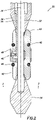
- FIG. 2 a more detailed view of an example of the anchor 30 is representatively illustrated.
- the anchor 30 is described below as it may be used in the well tool 20, system 10 and method of FIG. 1 , but the anchor 30 may be used with other well tools, systems and methods in keeping with the principles of this disclosure.
- an inner mandrel 32 extends longitudinally in the anchor 30, and is connected to a lower frusto-conical wedge 34.
- the inner mandrel 32 extends through an upper frusto-conical wedge 36.
- the actuator of the well tool 20 displaces the upper wedge 36 downward (e.g., along a longitudinal axis 38 of the well tool) relative to the inner mandrel 32 when the well tool is set in the wellbore 12. In this manner, a longitudinal distance between the wedges 34, 36 is decreased when the well tool 20 is set.
- a slip assembly 40 is carried on the inner mandrel 32.
- the slip assembly 40 is positioned longitudinally between the wedges 34, 36, so that, when the longitudinal distance between the wedges is decreased, slips 42 of the slip assembly 40 are displaced radially outward into gripping engagement with the well surface 24.
- the slip assembly 40 is slidably retained relative to the upper wedge 36 using multiple retainers 44 (only one of which is visible in FIG. 2 , see FIG. 5 ).
- the retainers 44 limit a longitudinal distance between the upper wedge 36 and the slip assembly 40, but permit the longitudinal distance to decrease when the well tool 20 is set, so that the upper wedge 36 can engage the slips 42 to displace the slips radially outward.
- the slip assembly 40 includes springs 46.
- the springs 46 bias the slips 42 radially inward, so that the slips are maintained in a radially retracted position when the well tool 20 is unset (as depicted in FIG. 2 ).
- the springs 46 are in the form of garter springs (circumferentially continuous coiled extension springs), which outwardly surround and encircle the slips 42.
- the slip assembly 40 also includes a slip retainer 48.
- the slip retainer 48 guides the radial displacement of the slips 42 and positions the slips, so that they are circumferentially distributed about the inner mandrel 32.
- the slip retainer 48 also engages the retainers 44, in order to limit longitudinal displacement of the slip assembly 40 relative to the upper wedge 36.
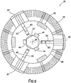
- FIG. 3 a cross-sectional view of the anchor 30, taken along line 3-3 of FIG. 2 , is representatively illustrated.
- the manner in which the slips 42 are circumferentially distributed about the inner mandrel 32 may be seen.
- three of the slips 42 are equally distributed at 120 degree intervals about the inner mandrel 32, but in other examples other numbers of slips may be used and the slips may be distributed or configured differently.
- FIG. 4 a cross-sectional view of the anchor 30 is representatively illustrated.
- the anchor 30 is in a set configuration in which the slips 42 are radially outwardly extended into gripping engagement with the well surface 24.
- FIG. 5 a cross-sectional view of the anchor 30 is representatively illustrated, taken along line 5-5 of FIG. 4 .
- the spring retainer 48 has a series of circumferentially distributed and radially extending slots 50 formed therein.
- Each of the slips 42 is slidably received in a respective one of the slots 50. In this manner, the circumferential separation of the slips 42 is maintained, while permitting the slips to displace radially outward and inward.
- FIGS. 6 & 7 side and front elevational views of an example of the slip 42 are representatively illustrated.
- the slip 42 depicted in FIGS. 6 & 7 may be used in the well tool 20 and anchor 30 described above, or it may be used with other well tools and anchors.
- the slip 42 includes longitudinally spaced apart grip structures 52.
- Each of the grip structures 52 is configured to grippingly engage a well surface.
- the grip structures 52 include inclined surfaces 54 formed thereon for cooperative engagement with the wedges 34, 36.
- the grip structures 52 have external grip surfaces 56 disposed thereon.
- the grip surfaces 56 are in the form of longitudinally spaced apart ridges or teeth formed on the grip structures 52, but in other examples the grip surfaces 56 could comprise embedded substances (such as carbide) or other components that enhance the gripping engagement between the slip 42 and the well surface.
- a lateral width GW of the grip surfaces 56 is greater than a lateral width LW of the beam 60.
- each of the recesses 58 is positioned longitudinally between one of the grip structures 52 and a beam 60 that connects the grip structures to each other.
- the beam 60 is configured for sliding engagement in one of the slots 50 in the slip retainer 48 (see FIG. 5 ).
- the beam 60 is radially displaceable in a slot 50 relative to the slip retainer 48.
- the beam 60 is also configured to resist bending moments experienced as a result of forces applied due to the gripping engagement between the grip structures 52 and the well surface, and due to engagement between the grip structures and the wedges 34, 36.
- a radial width RW of the beam 60 along a radial axis 62 intersecting a centroid 64 of the beam is greater than the lateral width LW of the beam along a lateral axis 66 intersecting the centroid.
- FIG. 8 a cross-sectional view of the beam 60, taken along line 8-8 of FIG. 7 is representatively illustrated.
- this view relative orientations between the axes 38, 62, 66, the centroid 64, the beam radial width RW and the beam lateral width LW may be clearly seen.
- the axes 38, 62, 66 are orthogonal to each other, and each of the axes 62, 66 passes through the centroid 64 of the beam 60.
- a second moment of area (also known as an area moment of inertia or a second area moment) of the beam about the lateral axis 66 is greater than a second moment of area of the beam about the radial axis 62.
- a bending strength of the beam 60 about the lateral axis 66 is greater than a bending strength of the beam about the radial axis 62.
- the retainers 44 prevent the slips 42 from being inadvertently set while the well tool 20 is being conveyed into the well in the unset position.
- the retainers 44 rest in longitudinal tracks that are machined into an outer surface of the mandrel 32 (see FIG. 5 ). Because lower ends of the retainers 44 are secured in the slip retainer 48, the retainers are fixed to the slip assembly 40 on that end.
- the retainers 44 are resting in the longitudinal tracks on the mandrel 32, and because these tracks do not run the full length of the mandrel, when the tool 20 is in an unset configuration (see FIG. 2 ), the retainers are, unable to displace significantly in either longitudinal direction. As a result, when the tool 20 is in the unset configuration and being conveyed into the well, it is not possible for the slips 42 to be inadvertently set in the event that they pass through a restriction or other obstruction in the well.
- the slip 42 can more effectively resist bending moments applied to the slip about a lateral axis 66 of the beam 60.
- the spring 46 is received in recesses 58 on an exterior of the slip 42, and does not interfere with or limit the extension or retraction of the slip.
- the above disclosure provides to the art a well tool 20 comprising a downhole anchor 30 including at least one outwardly extendable slip 42 configured to grip a well surface 24.
- the slip 42 in this example comprises longitudinally spaced apart grip structures 52, and a longitudinally extending beam 60 which connects the grip structures 52 to each other.
- the beam 60 has a radial thickness RW which is greater than a lateral width LW of the beam 60.
- Each of the grip structures 52 may comprise a grip surface 56.
- a lateral width GW of the grip surfaces 56 may be greater than the lateral width LW of the beam 60.
- a spring retainer recess 58 may be formed in the slip 42 longitudinally between the beam 60 and at least one of the grip structures 52.
- a spring 46 may be received in the spring retainer recess 58.
- the spring 46 may surround the slip 42.
- a garter spring 46 may be received in the spring retainer recess 58.
- the beam 60 may be received in a radially extending slot 50 formed in a slip retainer 48.
- a spring 46 may bias the slip 42 radially inward relative to the slip retainer 48, with the spring 46 surrounding the slip 42.
- An area moment of inertia of the beam 60 with respect to a lateral axis 66 through a centroid 64 of the beam 60 may be greater than an area moment of inertia of the beam 60 with respect to a radial axis 62 through the centroid 64 of the beam 60.
- Each of the lateral axis 66 and the radial axis 62 is perpendicular to a central longitudinal axis 38 of the well tool 20.
- the well tool 20 can include at least one retainer 44 having first and second opposite ends, the first opposite end being secured to the slip retainer 48, the second opposite end being reciprocably received in a wedge 36 that outwardly deflects the slip 42. Relative longitudinal displacement between the retainer 44 and the wedge 36 may be limited.
- a well tool 20 comprising a downhole anchor 30 including at least one outwardly extendable slip 42 configured to grip a well surface 24, a slip retainer 48 that retains the slip 42, and a spring 46 that inwardly biases the slip 42 relative to the slip retainer 48.
- the spring 46 surrounds the slip 42.
- the well tool 20 comprises a central longitudinal axis 38 and a downhole anchor 30 including at least one outwardly extendable slip 42 configured to grip a well surface 24.
- the slip 42 comprises longitudinally spaced apart grip structures 52 and a longitudinally extending beam 60 which connects the grip structures 52 to each other.
- An area moment of inertia of the beam 60 with respect to a lateral axis 66 through a centroid 64 of the beam 60 is greater than an area moment of inertia of the beam 60 with respect to a radial axis 62 through the centroid 64 of the beam 60.
- Each of the lateral axis 66 and the radial axis 62 is perpendicular to the central longitudinal axis 38.
Landscapes
- Life Sciences & Earth Sciences (AREA)
- Engineering & Computer Science (AREA)
- Geology (AREA)
- Mining & Mineral Resources (AREA)
- Physics & Mathematics (AREA)
- Environmental & Geological Engineering (AREA)
- Fluid Mechanics (AREA)
- General Life Sciences & Earth Sciences (AREA)
- Geochemistry & Mineralogy (AREA)
- Piles And Underground Anchors (AREA)
Abstract
Description
- This disclosure relates generally to equipment utilized and operations performed in conjunction with a subterranean well and, in an example described below, more particularly provides for strengthened slips of the type used in downhole anchors.
- A variety of different types of well tools can include a downhole anchor. For example, a packer, bridge plug or liner hanger uses an anchor to prevent displacement relative to a well surface (such as, an interior surface of a casing, liner or wellbore). The anchor can include an element known to those skilled in the art as a "slip," which is designed to grip the well surface.
- It will be appreciated that advancements are continually needed in the arts of designing, constructing and utilizing well tools with improved slips. The description below and the accompanying drawings provide such advancements, which may be used with a variety of different types of well tools and in a variety of different well systems.
-
US 4,359,090 discloses an anchoring mechanism for a well packer and includes plural bidirectional one piece slip members which are radially extendable into gripping engagement with a well conduit. The slip members are engaged by wedge surfaces on cooperating upper and lower slip cones. Only the lower slip cone is fitted with grooves which are adapted to receive laterally projecting tongues on the slip members for retaining the slip members in assembly with the remainder of the anchoring mechanism. The anchoring mechanism includes a plurality of longitudinally extending brackets having laterally projecting ears which are engageable with inclined slots cut in opposite longitudinal sides of the slip members. The bracket members are connected to the upper slip cone for movement therewith by shear screws. Relative movement of the upper slip cone and the brackets toward the lower slip cone results in setting the lower end of the slip members followed by shearing of the screws to obtain relative movement of the upper slip cone with respect to the brackets to set the upper end portion of the slip members in gripping engagement with the well conduit. -
US 4,059,150 discloses an anchoring assembly for anchoring well equipment within a surrounding well conduit. - An aspect of the present disclosure relates to a well tool according to claim 1. Optional features of the well tool as presented in the dependent claims.
- A well tool comprises:
- a central longitudinal axis; and
- a downhole anchor including at least one outwardly extendable slip configured to grip a well surface, the slip comprising longitudinally spaced apart grip structures, and a longitudinally extending beam which connects the grip structures to each other, and
- in which an area moment of inertia of the beam with respect to a lateral axis through a centroid of the beam is greater than an area moment of inertia of the beam with respect to a radial axis through the centroid of the beam, each of the lateral axis and the radial axis being perpendicular to the central longitudinal axis.
- Each of the grip structures may comprise a grip surface, and a lateral width of the grip surfaces is greater than the lateral width of the beam.
- A spring retainer recess may be formed in the slip longitudinally between the beam and at least one of the grip structures.
- A spring may be received in the spring retainer recess, and the spring surrounds the slip.
- The beam may be received in a radially extending slot formed in a slip retainer, a spring biases the slip radially inward relative to the slip retainer, and the spring surrounds the slip.
- The well tool may further comprise at least one retainer having first and second opposite ends, the first opposite end being secured to the slip retainer, the second opposite end being reciprocably received in a wedge that outwardly deflects the slip, and relative longitudinal displacement between the retainer and the wedge being limited.
- The beam may have a minimum radial thickness which is greater than a minimum lateral width of the beam.
- A well tool, comprises:
- a downhole anchor including at least one outwardly extendable slip configured to grip a well surface,
- the slip comprising longitudinally spaced apart grip structures, and a longitudinally extending beam which connects the grip structures to each other, and
- the beam having a radial thickness which is greater than a lateral width of the beam.
- Each of the grip structures may comprise a grip surface, and a lateral width of the grip surfaces is greater than the lateral width of the beam.
- A spring retainer recess may be formed in the slip longitudinally between the beam and at least one of the grip structures.
- A spring may be received in the spring retainer recess, and the spring surrounds the slip.
- A garter spring may be received in the spring retainer recess.
- The beam may be received in a radially extending slot formed in a slip retainer, a spring biases the slip radially inward relative to the slip retainer, and the spring surrounds the slip.
- A first area moment of inertia of the beam with respect to a lateral axis through a centroid of the beam may be greater than a second area moment of inertia of the beam with respect to a radial axis through the centroid of the beam, each of the lateral axis and the radial axis being perpendicular to a central longitudinal axis of the well tool.
- A well tool comprises:
- a downhole anchor including at least one outwardly extendable slip configured to grip a well surface, a slip retainer that retains the slip, and a spring that inwardly biases the slip relative to the slip retainer,
- in which the spring surrounds the slip.
- The spring may comprise a garter spring.
- The slip may comprise longitudinally spaced apart grip structures, and a longitudinally extending beam which connects the grip structures to each other.
- A first area moment of inertia of the beam with respect to a lateral axis through a centroid of the beam may be greater than a second area moment of inertia of the beam with respect to a radial axis through the centroid of the beam, each of the lateral axis and the radial axis being perpendicular to a central longitudinal axis of the well tool.
- The beam may have a radial thickness which is greater than a lateral width of the beam.
- The beam may be received in a radially extending slot formed in the slip retainer.
- A spring retainer recess may be formed in the slip longitudinally between the beam and at least one of the grip structures.
-
-
FIG. 1 is a representative partially cross-sectional view of an example of a well system and associated method which can embody principles of this disclosure. -
FIG. 2 is a representative cross-sectional view of an example of an anchor section of a well tool that may be used in the system and method ofFIG. 1 , and which can embody the principles of this disclosure. -
FIG. 3 is a representative cross-sectional view of the anchor section, taken along line 3-3 ofFIG. 2 . -
FIG. 4 is a representative cross-sectional view of the anchor section in a set configuration. -
FIG. 5 is a representative cross-sectional view of the anchor section, taken along line 5-5 ofFIG. 4 . -
FIG. 6 is a representative side view of an example of a slip of the anchor section. -
FIG. 7 is a representative front view of the slip. -
FIG. 8 is a representative cross-sectional view of the slip, taken along line 8-8 ofFIG. 7 . - Representatively illustrated in
FIG. 1 is asystem 10 for use with a subterranean well, and an associated method, which can embody principles of this disclosure. However, it should be clearly understood that thesystem 10 and method are merely one example of an application of the principles of this disclosure in practice, and a wide variety of other examples are possible. Therefore, the scope of this disclosure is not limited at all to the details of thesystem 10 and method described herein and/or depicted in the drawings. - In the
FIG. 1 example, awellbore 12 has been drilled into the earth, and the wellbore has been lined withcasing 14 andcement 16. In other examples, a section of thewellbore 12 in which the principles of this disclosure are practiced could be uncased or open hole. In addition, although thewellbore 12 is depicted inFIG. 1 as being generally vertical, in other examples the wellbore may be generally horizontal or otherwise inclined from vertical. - A
well tool 20 is conveyed into thewellbore 12 using a conveyance 18 (such as, a wireline, electric line, coiled tubing, production tubing, downhole tractor or robot, etc.). Thewell tool 20 could be a packer, a bridge plug, a liner hanger, or another type of well tool. In some examples, a conveyance may not be needed to position thewell tool 20 at a desired location in the wellbore 12 (e.g., the well tool could be pumped to the desired location). - It is desired in the
FIG. 1 example to seal off anannulus 22 formed radially between thewell tool 20 and aninterior well surface 24. As depicted inFIG. 1 , thewell surface 24 corresponds to an interior surface of thecasing 14. However, if thewellbore 12 is uncased, then thewell surface 24 could correspond to an inner wall surface of the wellbore. - For sealing against the
well surface 24, thewell tool 20 includes anannular seal 26. Theannular seal 26 is radially outwardly extendable into sealing engagement with the well surface 24 (such as, in response to activation of an actuator (not shown) of the well tool 20). - The
well tool 20 also includes ananchor 30 for grippingly engaging thewell surface 24. When theanchor 30 grips thewell surface 24, relative longitudinal displacement between thewell tool 20 and the well surface is prevented, thereby securing the well tool in thewellbore 12. In some examples, theanchor 30 may be actuated by the same actuator as is used to outwardly extend theannular seal 26. - Note that it is not necessary for the
well tool 20 to include theannular seal 26, or for the same actuator to be used to outwardly extend the annular seal and theanchor 30 into engagement with thewell surface 24. Thus, the scope of this disclosure is not limited to any particular details of thewell tool 20,annular seal 26 andanchor 30 as depicted inFIG. 1 or described herein. - Referring additionally now to
FIG. 2 , a more detailed view of an example of theanchor 30 is representatively illustrated. For clarity and convenience, theanchor 30 is described below as it may be used in thewell tool 20,system 10 and method ofFIG. 1 , but theanchor 30 may be used with other well tools, systems and methods in keeping with the principles of this disclosure. - As depicted in
FIG. 2 , aninner mandrel 32 extends longitudinally in theanchor 30, and is connected to a lower frusto-conical wedge 34. Theinner mandrel 32 extends through an upper frusto-conical wedge 36. - In this example, the actuator of the
well tool 20 displaces theupper wedge 36 downward (e.g., along alongitudinal axis 38 of the well tool) relative to theinner mandrel 32 when the well tool is set in thewellbore 12. In this manner, a longitudinal distance between thewedges well tool 20 is set. - A
slip assembly 40 is carried on theinner mandrel 32. Theslip assembly 40 is positioned longitudinally between thewedges slip assembly 40 are displaced radially outward into gripping engagement with thewell surface 24. - In the
FIG. 2 example, theslip assembly 40 is slidably retained relative to theupper wedge 36 using multiple retainers 44 (only one of which is visible inFIG. 2 , seeFIG. 5 ). Theretainers 44 limit a longitudinal distance between theupper wedge 36 and theslip assembly 40, but permit the longitudinal distance to decrease when thewell tool 20 is set, so that theupper wedge 36 can engage theslips 42 to displace the slips radially outward. - The
slip assembly 40 includessprings 46. Thesprings 46 bias theslips 42 radially inward, so that the slips are maintained in a radially retracted position when thewell tool 20 is unset (as depicted inFIG. 2 ). In this example, thesprings 46 are in the form of garter springs (circumferentially continuous coiled extension springs), which outwardly surround and encircle theslips 42. - The
slip assembly 40 also includes aslip retainer 48. Theslip retainer 48 guides the radial displacement of theslips 42 and positions the slips, so that they are circumferentially distributed about theinner mandrel 32. Theslip retainer 48 also engages theretainers 44, in order to limit longitudinal displacement of theslip assembly 40 relative to theupper wedge 36. - Referring additionally now to
FIG. 3 , a cross-sectional view of theanchor 30, taken along line 3-3 ofFIG. 2 , is representatively illustrated. In this view, the manner in which theslips 42 are circumferentially distributed about theinner mandrel 32 may be seen. In this example, three of theslips 42 are equally distributed at 120 degree intervals about theinner mandrel 32, but in other examples other numbers of slips may be used and the slips may be distributed or configured differently. - Referring additionally now to
FIG. 4 , a cross-sectional view of theanchor 30 is representatively illustrated. In this view, theanchor 30 is in a set configuration in which theslips 42 are radially outwardly extended into gripping engagement with thewell surface 24. - Note that the longitudinal distance between the
wedges FIG. 2 . Thesprings 46 continue to radially inwardly bias theslips 42 so that, if theanchor 30 is subsequently unset, the slips will radially retract out of engagement with thewell surface 24. - Referring additionally now to
FIG. 5 , a cross-sectional view of theanchor 30 is representatively illustrated, taken along line 5-5 ofFIG. 4 . In this view, it may be seen that thespring retainer 48 has a series of circumferentially distributed and radially extendingslots 50 formed therein. - Each of the
slips 42 is slidably received in a respective one of theslots 50. In this manner, the circumferential separation of theslips 42 is maintained, while permitting the slips to displace radially outward and inward. - Referring additionally now to
FIGS. 6 & 7 , side and front elevational views of an example of theslip 42 are representatively illustrated. Theslip 42 depicted inFIGS. 6 & 7 may be used in thewell tool 20 andanchor 30 described above, or it may be used with other well tools and anchors. - In the
FIGS. 6 & 7 example, theslip 42 includes longitudinally spaced apart gripstructures 52. Each of thegrip structures 52 is configured to grippingly engage a well surface. In addition, thegrip structures 52 includeinclined surfaces 54 formed thereon for cooperative engagement with thewedges - For enhanced gripping of the well surface, the
grip structures 52 have external grip surfaces 56 disposed thereon. In this example, the grip surfaces 56 are in the form of longitudinally spaced apart ridges or teeth formed on thegrip structures 52, but in other examples the grip surfaces 56 could comprise embedded substances (such as carbide) or other components that enhance the gripping engagement between theslip 42 and the well surface. As depicted inFIG. 7 , a lateral width GW of the grip surfaces 56 is greater than a lateral width LW of thebeam 60. - Laterally extending spring retainer recesses 58 are formed in the
slip 42. In theslip assembly 40, thesprings 46 are received in the spring retainer recesses 58 (seeFIG. 4 ). In this example, each of therecesses 58 is positioned longitudinally between one of thegrip structures 52 and abeam 60 that connects the grip structures to each other. - The
beam 60 is configured for sliding engagement in one of theslots 50 in the slip retainer 48 (seeFIG. 5 ). Thebeam 60 is radially displaceable in aslot 50 relative to theslip retainer 48. - The
beam 60 is also configured to resist bending moments experienced as a result of forces applied due to the gripping engagement between thegrip structures 52 and the well surface, and due to engagement between the grip structures and thewedges beam 60 along aradial axis 62 intersecting acentroid 64 of the beam is greater than the lateral width LW of the beam along alateral axis 66 intersecting the centroid. - Referring additionally now to
FIG. 8 , a cross-sectional view of thebeam 60, taken along line 8-8 ofFIG. 7 is representatively illustrated. In this view, relative orientations between theaxes centroid 64, the beam radial width RW and the beam lateral width LW may be clearly seen. Note that theaxes axes centroid 64 of thebeam 60. - As a result of the unique configuration of the
beam 60, a second moment of area (also known as an area moment of inertia or a second area moment) of the beam about thelateral axis 66 is greater than a second moment of area of the beam about theradial axis 62. Thus, a bending strength of thebeam 60 about thelateral axis 66 is greater than a bending strength of the beam about theradial axis 62. - In the
FIGS. 2-5 example described above, theretainers 44 prevent theslips 42 from being inadvertently set while thewell tool 20 is being conveyed into the well in the unset position. Theretainers 44 rest in longitudinal tracks that are machined into an outer surface of the mandrel 32 (seeFIG. 5 ). Because lower ends of theretainers 44 are secured in theslip retainer 48, the retainers are fixed to theslip assembly 40 on that end. - Furthermore, because the
retainers 44 are resting in the longitudinal tracks on themandrel 32, and because these tracks do not run the full length of the mandrel, when thetool 20 is in an unset configuration (seeFIG. 2 ), the retainers are, unable to displace significantly in either longitudinal direction. As a result, when thetool 20 is in the unset configuration and being conveyed into the well, it is not possible for theslips 42 to be inadvertently set in the event that they pass through a restriction or other obstruction in the well. - In the set configuration (see
FIG. 4 ), once thelower wedge 34 has moved up relative to theupper wedge 34, theentire slip assembly 40 moves up with thelower wedge 34. Since theretainers 44 are constrained to theslip retainer 48, as theslip assembly 40 displaces upward, so too do the retainers. - As a result, when it comes time to retract the
slips 42 and retrieve thetool 20, when theupper wedge 36 is pulled up and away from thelower wedge 34, an internal shoulder in theupper wedge 36 contacts upper shoulders of theretainers 44, thus pulling them upwards as well. Because theretainers 44 are constrained to theslip assembly 40, when theupper wedge 36 is pulled up and away from thelower wedge 34, it also pulls theslip assembly 40 off of thelower wedge 34, thus fully retracting theslips 42. - It may now be fully appreciated that the above disclosure provides significant advances to the arts of designing, constructing and utilizing well tools with improved slips. In examples described above, the
slip 42 can more effectively resist bending moments applied to the slip about alateral axis 66 of thebeam 60. In addition, thespring 46 is received inrecesses 58 on an exterior of theslip 42, and does not interfere with or limit the extension or retraction of the slip. - The above disclosure provides to the art a
well tool 20 comprising adownhole anchor 30 including at least one outwardlyextendable slip 42 configured to grip awell surface 24. Theslip 42 in this example comprises longitudinally spaced apart gripstructures 52, and alongitudinally extending beam 60 which connects thegrip structures 52 to each other. Thebeam 60 has a radial thickness RW which is greater than a lateral width LW of thebeam 60. - In any of the well tool examples described herein:
Each of thegrip structures 52 may comprise agrip surface 56. A lateral width GW of the grip surfaces 56 may be greater than the lateral width LW of thebeam 60. - A
spring retainer recess 58 may be formed in theslip 42 longitudinally between thebeam 60 and at least one of thegrip structures 52. Aspring 46 may be received in thespring retainer recess 58. Thespring 46 may surround theslip 42. Agarter spring 46 may be received in thespring retainer recess 58. - The
beam 60 may be received in aradially extending slot 50 formed in aslip retainer 48. Aspring 46 may bias theslip 42 radially inward relative to theslip retainer 48, with thespring 46 surrounding theslip 42. - An area moment of inertia of the
beam 60 with respect to alateral axis 66 through acentroid 64 of thebeam 60 may be greater than an area moment of inertia of thebeam 60 with respect to aradial axis 62 through thecentroid 64 of thebeam 60. Each of thelateral axis 66 and theradial axis 62 is perpendicular to a centrallongitudinal axis 38 of thewell tool 20. - The
well tool 20 can include at least oneretainer 44 having first and second opposite ends, the first opposite end being secured to theslip retainer 48, the second opposite end being reciprocably received in awedge 36 that outwardly deflects theslip 42. Relative longitudinal displacement between theretainer 44 and thewedge 36 may be limited. - The above disclosure also provides to the art a
well tool 20 comprising adownhole anchor 30 including at least one outwardlyextendable slip 42 configured to grip awell surface 24, aslip retainer 48 that retains theslip 42, and aspring 46 that inwardly biases theslip 42 relative to theslip retainer 48. Thespring 46 surrounds theslip 42. - Another
well tool 20 is provided to the art by the above disclosure. In this example, thewell tool 20 comprises a centrallongitudinal axis 38 and adownhole anchor 30 including at least one outwardlyextendable slip 42 configured to grip awell surface 24. Theslip 42 comprises longitudinally spaced apart gripstructures 52 and alongitudinally extending beam 60 which connects thegrip structures 52 to each other. An area moment of inertia of thebeam 60 with respect to alateral axis 66 through acentroid 64 of thebeam 60 is greater than an area moment of inertia of thebeam 60 with respect to aradial axis 62 through thecentroid 64 of thebeam 60. Each of thelateral axis 66 and theradial axis 62 is perpendicular to the centrallongitudinal axis 38. - Although various examples have been described above, with each example having certain features, it should be understood that it is not necessary for a particular feature of one example to be used exclusively with that example. Instead, any of the features described above and/or depicted in the drawings can be combined with any of the examples, in addition to or in substitution for any of the other features of those examples. One example's features are not mutually exclusive to another example's features.
- Although each example described above includes a certain combination of features, it should be understood that it is not necessary for all features of an example to be used. Instead, any of the features described above can be used, without any other particular feature or features also being used.
- It should be understood that the various embodiments described herein may be utilized in various orientations, such as inclined, inverted, horizontal, vertical, etc., and in various configurations.
- In the above description of the representative examples, directional terms (such as "above," "below," "upper," "lower," "upward," "downward," etc.) are used for convenience in referring to the accompanying drawings.
- The terms "including," "includes," "comprising," "comprises," and similar terms are used in a non-limiting sense in this specification. For example, if a system, method, apparatus, device, etc., is described as "including" a certain feature or element, the system, method, apparatus, device, etc., can include that feature or element, and can also include other features or elements. Similarly, the term "comprises" is considered to mean "comprises, but is not limited to."
- Structures disclosed as being separately formed can, in other examples, be integrally formed and vice versa. The foregoing detailed description is to be clearly understood as being given by way of illustration and example only, the scope of the invention being limited solely by the appended claims.
Claims (7)
- A well tool (20), comprising:a central longitudinal axis (38); anda downhole anchor (30) including at least one outwardly extendable slip (42) configured to grip a well surface (24), the slip (42) comprising longitudinally spaced apart grip structures (52), and a longitudinally extending beam (60) which connects the grip structures (52) to each other, andin which an area moment of inertia of the beam (60) with respect to a lateral axis (66) through a centroid (64) of the beam (60) is greater than an area moment of inertia of the beam (60) with respect to a radial axis (62) through the centroid (64) of the beam (60), each of the lateral axis (66) and the radial axis (62) being perpendicular to the central longitudinal axis (38).
- The well tool (20) of claim 1, in which each of the grip structures (52) comprises a grip surface (56), and a lateral width (GW) of the grip surfaces (56) is greater than the lateral width (LW) of the beam (60).
- The well tool (20) of claim 1, in which a spring retainer recess (58) is formed in the slip (42) longitudinally between the beam (60) and at least one of the grip structures (56).
- The well tool (20) of claim 3, in which a spring (46) is received in the spring retainer recess (58), and the spring (46) surrounds the slip (42).
- The well tool (20) of claim 1, in which the beam (60) is received in a radially extending slot (50) formed in a slip retainer (48), a spring (46) biases the slip (42) radially inward relative to the slip retainer (48), and the spring (46) surrounds the slip (42).
- The well tool (20) of claim 5, further comprising at least one retainer (44) having first and second opposite ends, the first opposite end being secured to the slip retainer (48), the second opposite end being reciprocably received in a wedge (36) that outwardly deflects the slip (42), and relative longitudinal displacement between the retainer (44) and the wedge (36) being limited.
- The well tool (20) of claim 1, in which the beam (60) has a minimum radial thickness (RW) which is greater than a minimum lateral width (LW) of the beam (60).
Applications Claiming Priority (3)
| Application Number | Priority Date | Filing Date | Title |
|---|---|---|---|
| US16/509,643 US11111745B2 (en) | 2019-07-12 | 2019-07-12 | Downhole anchor with strengthened slips for well tool |
| EP20746831.5A EP3966420B1 (en) | 2019-07-12 | 2020-07-10 | Downhole anchor with strengthened slips for well tool |
| PCT/US2020/041715 WO2021011419A1 (en) | 2019-07-12 | 2020-07-10 | Downhole anchor with strengthened slips for well tool |
Related Parent Applications (2)
| Application Number | Title | Priority Date | Filing Date |
|---|---|---|---|
| EP20746831.5A Division EP3966420B1 (en) | 2019-07-12 | 2020-07-10 | Downhole anchor with strengthened slips for well tool |
| EP20746831.5A Division-Into EP3966420B1 (en) | 2019-07-12 | 2020-07-10 | Downhole anchor with strengthened slips for well tool |
Publications (2)
| Publication Number | Publication Date |
|---|---|
| EP4074940A1 true EP4074940A1 (en) | 2022-10-19 |
| EP4074940B1 EP4074940B1 (en) | 2023-08-30 |
Family
ID=71833490
Family Applications (2)
| Application Number | Title | Priority Date | Filing Date |
|---|---|---|---|
| EP20746831.5A Active EP3966420B1 (en) | 2019-07-12 | 2020-07-10 | Downhole anchor with strengthened slips for well tool |
| EP22178108.1A Active EP4074940B1 (en) | 2019-07-12 | 2020-07-10 | Downhole anchor with strengthened slips for well tool |
Family Applications Before (1)
| Application Number | Title | Priority Date | Filing Date |
|---|---|---|---|
| EP20746831.5A Active EP3966420B1 (en) | 2019-07-12 | 2020-07-10 | Downhole anchor with strengthened slips for well tool |
Country Status (4)
| Country | Link |
|---|---|
| US (1) | US11111745B2 (en) |
| EP (2) | EP3966420B1 (en) |
| DK (2) | DK3966420T3 (en) |
| WO (1) | WO2021011419A1 (en) |
Families Citing this family (2)
| Publication number | Priority date | Publication date | Assignee | Title |
|---|---|---|---|---|
| CA3181034A1 (en) | 2021-11-03 | 2023-05-03 | Oilify New-Tech Solutions Inc. | Downhole anchoring mechanism |
| CN114251067B (en) * | 2021-12-22 | 2024-07-09 | 中海油田服务股份有限公司 | Underground tool anchoring structure |
Citations (8)
| Publication number | Priority date | Publication date | Assignee | Title |
|---|---|---|---|---|
| US2187482A (en) * | 1938-12-12 | 1940-01-16 | Baker Oil Tools Inc | Cement retainer |
| US2355199A (en) * | 1940-05-06 | 1944-08-08 | Bassinger Ross | Well plug |
| US3379257A (en) * | 1965-10-14 | 1968-04-23 | Otis Eng Co | Anchoring devices for well tools |
| US4059150A (en) | 1976-02-09 | 1977-11-22 | Brown Oil Tools, Inc. | Anchoring assembly |
| US4359090A (en) | 1981-08-31 | 1982-11-16 | Baker International Corporation | Anchoring mechanism for well packer |
| US20040055421A1 (en) * | 1996-09-13 | 2004-03-25 | Bangert Daniel S. | Granular particle gripping surface |
| US20150090441A1 (en) * | 2012-04-27 | 2015-04-02 | Altus Intervention As | Anchor mechanism for use in a well |
| US20180216429A1 (en) * | 2015-08-27 | 2018-08-02 | Halliburton Energy Services, Inc. | Bidirectional slips |
Family Cites Families (3)
| Publication number | Priority date | Publication date | Assignee | Title |
|---|---|---|---|---|
| US3722588A (en) * | 1971-10-18 | 1973-03-27 | J Tamplen | Seal assembly |
| US4702313A (en) * | 1985-05-28 | 1987-10-27 | Dresser Industries, Inc. | Slip and slip assembly for well tools |
| US7255172B2 (en) * | 2004-04-13 | 2007-08-14 | Tech Tac Company, Inc. | Hydrodynamic, down-hole anchor |
-
2019
- 2019-07-12 US US16/509,643 patent/US11111745B2/en active Active
-
2020
- 2020-07-10 EP EP20746831.5A patent/EP3966420B1/en active Active
- 2020-07-10 DK DK20746831.5T patent/DK3966420T3/en active
- 2020-07-10 DK DK22178108.1T patent/DK4074940T3/en active
- 2020-07-10 WO PCT/US2020/041715 patent/WO2021011419A1/en not_active Ceased
- 2020-07-10 EP EP22178108.1A patent/EP4074940B1/en active Active
Patent Citations (8)
| Publication number | Priority date | Publication date | Assignee | Title |
|---|---|---|---|---|
| US2187482A (en) * | 1938-12-12 | 1940-01-16 | Baker Oil Tools Inc | Cement retainer |
| US2355199A (en) * | 1940-05-06 | 1944-08-08 | Bassinger Ross | Well plug |
| US3379257A (en) * | 1965-10-14 | 1968-04-23 | Otis Eng Co | Anchoring devices for well tools |
| US4059150A (en) | 1976-02-09 | 1977-11-22 | Brown Oil Tools, Inc. | Anchoring assembly |
| US4359090A (en) | 1981-08-31 | 1982-11-16 | Baker International Corporation | Anchoring mechanism for well packer |
| US20040055421A1 (en) * | 1996-09-13 | 2004-03-25 | Bangert Daniel S. | Granular particle gripping surface |
| US20150090441A1 (en) * | 2012-04-27 | 2015-04-02 | Altus Intervention As | Anchor mechanism for use in a well |
| US20180216429A1 (en) * | 2015-08-27 | 2018-08-02 | Halliburton Energy Services, Inc. | Bidirectional slips |
Also Published As
| Publication number | Publication date |
|---|---|
| US11111745B2 (en) | 2021-09-07 |
| EP4074940B1 (en) | 2023-08-30 |
| DK3966420T3 (en) | 2022-09-26 |
| EP3966420A1 (en) | 2022-03-16 |
| EP3966420B1 (en) | 2022-07-27 |
| US20210010339A1 (en) | 2021-01-14 |
| WO2021011419A1 (en) | 2021-01-21 |
| DK4074940T3 (en) | 2023-11-20 |
Similar Documents
| Publication | Publication Date | Title |
|---|---|---|
| AU2022209206B2 (en) | Expanding and collapsing apparatus and methods of use | |
| AU2022201659B2 (en) | A rotating control device | |
| US20220325589A1 (en) | Well tool anchor and associated methods | |
| EP2412921B1 (en) | Apparatus and method for depth referencing downhole tubular strings | |
| WO2013172856A1 (en) | Wellbore anchoring system | |
| US20150060049A1 (en) | Retractable Collet Assembly for Liner String Installation in a Wellbore | |
| EP4074940B1 (en) | Downhole anchor with strengthened slips for well tool | |
| EP3899196B1 (en) | High expansion well tool and associated methods | |
| EP3143234B1 (en) | Mill blade torque support | |
| EP2643543A2 (en) | Entry guide formation on a well liner hanger | |
| US9695669B2 (en) | Well packer with nonrotating mandrel lock device | |
| EP1201875A2 (en) | Downhole tool | |
| EP3631153B1 (en) | Shifting tool resettable downhole | |
| AU2011332151B2 (en) | Entry guide formation on a well liner hanger | |
| GB2411678A (en) | Orienting and locating a well operation in a borehole |
Legal Events
| Date | Code | Title | Description |
|---|---|---|---|
| PUAI | Public reference made under article 153(3) epc to a published international application that has entered the european phase |
Free format text: ORIGINAL CODE: 0009012 |
|
| STAA | Information on the status of an ep patent application or granted ep patent |
Free format text: STATUS: REQUEST FOR EXAMINATION WAS MADE |
|
| 17P | Request for examination filed |
Effective date: 20220609 |
|
| AC | Divisional application: reference to earlier application |
Ref document number: 3966420 Country of ref document: EP Kind code of ref document: P |
|
| AK | Designated contracting states |
Kind code of ref document: A1 Designated state(s): AL AT BE BG CH CY CZ DE DK EE ES FI FR GB GR HR HU IE IS IT LI LT LU LV MC MK MT NL NO PL PT RO RS SE SI SK SM TR |
|
| GRAP | Despatch of communication of intention to grant a patent |
Free format text: ORIGINAL CODE: EPIDOSNIGR1 |
|
| STAA | Information on the status of an ep patent application or granted ep patent |
Free format text: STATUS: GRANT OF PATENT IS INTENDED |
|
| GRAS | Grant fee paid |
Free format text: ORIGINAL CODE: EPIDOSNIGR3 |
|
| INTG | Intention to grant announced |
Effective date: 20230626 |
|
| GRAA | (expected) grant |
Free format text: ORIGINAL CODE: 0009210 |
|
| STAA | Information on the status of an ep patent application or granted ep patent |
Free format text: STATUS: THE PATENT HAS BEEN GRANTED |
|
| AC | Divisional application: reference to earlier application |
Ref document number: 3966420 Country of ref document: EP Kind code of ref document: P |
|
| AK | Designated contracting states |
Kind code of ref document: B1 Designated state(s): AL AT BE BG CH CY CZ DE DK EE ES FI FR GB GR HR HU IE IS IT LI LT LU LV MC MK MT NL NO PL PT RO RS SE SI SK SM TR |
|
| REG | Reference to a national code |
Ref country code: GB Ref legal event code: FG4D |
|
| REG | Reference to a national code |
Ref country code: CH Ref legal event code: EP |
|
| REG | Reference to a national code |
Ref country code: DE Ref legal event code: R096 Ref document number: 602020016980 Country of ref document: DE |
|
| REG | Reference to a national code |
Ref country code: IE Ref legal event code: FG4D |
|
| P01 | Opt-out of the competence of the unified patent court (upc) registered |
Effective date: 20230922 |
|
| REG | Reference to a national code |
Ref country code: DK Ref legal event code: T3 Effective date: 20231117 |
|
| REG | Reference to a national code |
Ref country code: NL Ref legal event code: FP |
|
| REG | Reference to a national code |
Ref country code: LT Ref legal event code: MG9D |
|
| REG | Reference to a national code |
Ref country code: NO Ref legal event code: T2 Effective date: 20230830 |
|
| REG | Reference to a national code |
Ref country code: AT Ref legal event code: MK05 Ref document number: 1605678 Country of ref document: AT Kind code of ref document: T Effective date: 20230830 |
|
| PG25 | Lapsed in a contracting state [announced via postgrant information from national office to epo] |
Ref country code: GR Free format text: LAPSE BECAUSE OF FAILURE TO SUBMIT A TRANSLATION OF THE DESCRIPTION OR TO PAY THE FEE WITHIN THE PRESCRIBED TIME-LIMIT Effective date: 20231201 |
|
| PG25 | Lapsed in a contracting state [announced via postgrant information from national office to epo] |
Ref country code: IS Free format text: LAPSE BECAUSE OF FAILURE TO SUBMIT A TRANSLATION OF THE DESCRIPTION OR TO PAY THE FEE WITHIN THE PRESCRIBED TIME-LIMIT Effective date: 20231230 |
|
| PG25 | Lapsed in a contracting state [announced via postgrant information from national office to epo] |
Ref country code: SE Free format text: LAPSE BECAUSE OF FAILURE TO SUBMIT A TRANSLATION OF THE DESCRIPTION OR TO PAY THE FEE WITHIN THE PRESCRIBED TIME-LIMIT Effective date: 20230830 Ref country code: RS Free format text: LAPSE BECAUSE OF FAILURE TO SUBMIT A TRANSLATION OF THE DESCRIPTION OR TO PAY THE FEE WITHIN THE PRESCRIBED TIME-LIMIT Effective date: 20230830 Ref country code: LV Free format text: LAPSE BECAUSE OF FAILURE TO SUBMIT A TRANSLATION OF THE DESCRIPTION OR TO PAY THE FEE WITHIN THE PRESCRIBED TIME-LIMIT Effective date: 20230830 Ref country code: LT Free format text: LAPSE BECAUSE OF FAILURE TO SUBMIT A TRANSLATION OF THE DESCRIPTION OR TO PAY THE FEE WITHIN THE PRESCRIBED TIME-LIMIT Effective date: 20230830 Ref country code: IS Free format text: LAPSE BECAUSE OF FAILURE TO SUBMIT A TRANSLATION OF THE DESCRIPTION OR TO PAY THE FEE WITHIN THE PRESCRIBED TIME-LIMIT Effective date: 20231230 Ref country code: HR Free format text: LAPSE BECAUSE OF FAILURE TO SUBMIT A TRANSLATION OF THE DESCRIPTION OR TO PAY THE FEE WITHIN THE PRESCRIBED TIME-LIMIT Effective date: 20230830 Ref country code: GR Free format text: LAPSE BECAUSE OF FAILURE TO SUBMIT A TRANSLATION OF THE DESCRIPTION OR TO PAY THE FEE WITHIN THE PRESCRIBED TIME-LIMIT Effective date: 20231201 Ref country code: FI Free format text: LAPSE BECAUSE OF FAILURE TO SUBMIT A TRANSLATION OF THE DESCRIPTION OR TO PAY THE FEE WITHIN THE PRESCRIBED TIME-LIMIT Effective date: 20230830 Ref country code: AT Free format text: LAPSE BECAUSE OF FAILURE TO SUBMIT A TRANSLATION OF THE DESCRIPTION OR TO PAY THE FEE WITHIN THE PRESCRIBED TIME-LIMIT Effective date: 20230830 |
|
| PG25 | Lapsed in a contracting state [announced via postgrant information from national office to epo] |
Ref country code: PL Free format text: LAPSE BECAUSE OF FAILURE TO SUBMIT A TRANSLATION OF THE DESCRIPTION OR TO PAY THE FEE WITHIN THE PRESCRIBED TIME-LIMIT Effective date: 20230830 |
|
| PG25 | Lapsed in a contracting state [announced via postgrant information from national office to epo] |
Ref country code: ES Free format text: LAPSE BECAUSE OF FAILURE TO SUBMIT A TRANSLATION OF THE DESCRIPTION OR TO PAY THE FEE WITHIN THE PRESCRIBED TIME-LIMIT Effective date: 20230830 |
|
| PG25 | Lapsed in a contracting state [announced via postgrant information from national office to epo] |
Ref country code: SM Free format text: LAPSE BECAUSE OF FAILURE TO SUBMIT A TRANSLATION OF THE DESCRIPTION OR TO PAY THE FEE WITHIN THE PRESCRIBED TIME-LIMIT Effective date: 20230830 Ref country code: RO Free format text: LAPSE BECAUSE OF FAILURE TO SUBMIT A TRANSLATION OF THE DESCRIPTION OR TO PAY THE FEE WITHIN THE PRESCRIBED TIME-LIMIT Effective date: 20230830 Ref country code: ES Free format text: LAPSE BECAUSE OF FAILURE TO SUBMIT A TRANSLATION OF THE DESCRIPTION OR TO PAY THE FEE WITHIN THE PRESCRIBED TIME-LIMIT Effective date: 20230830 Ref country code: EE Free format text: LAPSE BECAUSE OF FAILURE TO SUBMIT A TRANSLATION OF THE DESCRIPTION OR TO PAY THE FEE WITHIN THE PRESCRIBED TIME-LIMIT Effective date: 20230830 Ref country code: CZ Free format text: LAPSE BECAUSE OF FAILURE TO SUBMIT A TRANSLATION OF THE DESCRIPTION OR TO PAY THE FEE WITHIN THE PRESCRIBED TIME-LIMIT Effective date: 20230830 Ref country code: PT Free format text: LAPSE BECAUSE OF FAILURE TO SUBMIT A TRANSLATION OF THE DESCRIPTION OR TO PAY THE FEE WITHIN THE PRESCRIBED TIME-LIMIT Effective date: 20240102 Ref country code: SK Free format text: LAPSE BECAUSE OF FAILURE TO SUBMIT A TRANSLATION OF THE DESCRIPTION OR TO PAY THE FEE WITHIN THE PRESCRIBED TIME-LIMIT Effective date: 20230830 |
|
| PG25 | Lapsed in a contracting state [announced via postgrant information from national office to epo] |
Ref country code: IT Free format text: LAPSE BECAUSE OF FAILURE TO SUBMIT A TRANSLATION OF THE DESCRIPTION OR TO PAY THE FEE WITHIN THE PRESCRIBED TIME-LIMIT Effective date: 20230830 |
|
| REG | Reference to a national code |
Ref country code: DE Ref legal event code: R097 Ref document number: 602020016980 Country of ref document: DE |
|
| PLBE | No opposition filed within time limit |
Free format text: ORIGINAL CODE: 0009261 |
|
| STAA | Information on the status of an ep patent application or granted ep patent |
Free format text: STATUS: NO OPPOSITION FILED WITHIN TIME LIMIT |
|
| PG25 | Lapsed in a contracting state [announced via postgrant information from national office to epo] |
Ref country code: SI Free format text: LAPSE BECAUSE OF FAILURE TO SUBMIT A TRANSLATION OF THE DESCRIPTION OR TO PAY THE FEE WITHIN THE PRESCRIBED TIME-LIMIT Effective date: 20230830 |
|
| 26N | No opposition filed |
Effective date: 20240603 |
|
| PG25 | Lapsed in a contracting state [announced via postgrant information from national office to epo] |
Ref country code: BG Free format text: LAPSE BECAUSE OF FAILURE TO SUBMIT A TRANSLATION OF THE DESCRIPTION OR TO PAY THE FEE WITHIN THE PRESCRIBED TIME-LIMIT Effective date: 20230830 |
|
| PG25 | Lapsed in a contracting state [announced via postgrant information from national office to epo] |
Ref country code: BG Free format text: LAPSE BECAUSE OF FAILURE TO SUBMIT A TRANSLATION OF THE DESCRIPTION OR TO PAY THE FEE WITHIN THE PRESCRIBED TIME-LIMIT Effective date: 20230830 |
|
| REG | Reference to a national code |
Ref country code: DE Ref legal event code: R119 Ref document number: 602020016980 Country of ref document: DE |
|
| PG25 | Lapsed in a contracting state [announced via postgrant information from national office to epo] |
Ref country code: MC Free format text: LAPSE BECAUSE OF FAILURE TO SUBMIT A TRANSLATION OF THE DESCRIPTION OR TO PAY THE FEE WITHIN THE PRESCRIBED TIME-LIMIT Effective date: 20230830 |
|
| REG | Reference to a national code |
Ref country code: CH Ref legal event code: PL |
|
| PG25 | Lapsed in a contracting state [announced via postgrant information from national office to epo] |
Ref country code: LU Free format text: LAPSE BECAUSE OF NON-PAYMENT OF DUE FEES Effective date: 20240710 |
|
| PG25 | Lapsed in a contracting state [announced via postgrant information from national office to epo] |
Ref country code: LU Free format text: LAPSE BECAUSE OF NON-PAYMENT OF DUE FEES Effective date: 20240710 |
|
| PG25 | Lapsed in a contracting state [announced via postgrant information from national office to epo] |
Ref country code: DE Free format text: LAPSE BECAUSE OF NON-PAYMENT OF DUE FEES Effective date: 20250201 |
|
| PG25 | Lapsed in a contracting state [announced via postgrant information from national office to epo] |
Ref country code: CH Free format text: LAPSE BECAUSE OF NON-PAYMENT OF DUE FEES Effective date: 20240731 Ref country code: BE Free format text: LAPSE BECAUSE OF NON-PAYMENT OF DUE FEES Effective date: 20240731 |
|
| PG25 | Lapsed in a contracting state [announced via postgrant information from national office to epo] |
Ref country code: FR Free format text: LAPSE BECAUSE OF NON-PAYMENT OF DUE FEES Effective date: 20240731 |
|
| REG | Reference to a national code |
Ref country code: BE Ref legal event code: MM Effective date: 20240731 |
|
| PG25 | Lapsed in a contracting state [announced via postgrant information from national office to epo] |
Ref country code: IE Free format text: LAPSE BECAUSE OF NON-PAYMENT OF DUE FEES Effective date: 20240710 |
|
| PGFP | Annual fee paid to national office [announced via postgrant information from national office to epo] |
Ref country code: DK Payment date: 20250714 Year of fee payment: 6 |
|
| PGFP | Annual fee paid to national office [announced via postgrant information from national office to epo] |
Ref country code: NO Payment date: 20250709 Year of fee payment: 6 |
|
| PG25 | Lapsed in a contracting state [announced via postgrant information from national office to epo] |
Ref country code: CY Free format text: LAPSE BECAUSE OF FAILURE TO SUBMIT A TRANSLATION OF THE DESCRIPTION OR TO PAY THE FEE WITHIN THE PRESCRIBED TIME-LIMIT; INVALID AB INITIO Effective date: 20200710 |
|
| PG25 | Lapsed in a contracting state [announced via postgrant information from national office to epo] |
Ref country code: HU Free format text: LAPSE BECAUSE OF FAILURE TO SUBMIT A TRANSLATION OF THE DESCRIPTION OR TO PAY THE FEE WITHIN THE PRESCRIBED TIME-LIMIT; INVALID AB INITIO Effective date: 20200710 |
|
| PG25 | Lapsed in a contracting state [announced via postgrant information from national office to epo] |
Ref country code: TR Free format text: LAPSE BECAUSE OF FAILURE TO SUBMIT A TRANSLATION OF THE DESCRIPTION OR TO PAY THE FEE WITHIN THE PRESCRIBED TIME-LIMIT Effective date: 20230830 |
|
| PGFP | Annual fee paid to national office [announced via postgrant information from national office to epo] |
Ref country code: GB Payment date: 20260608 Year of fee payment: 7 |
|
| PGFP | Annual fee paid to national office [announced via postgrant information from national office to epo] |
Ref country code: NL Payment date: 20260615 Year of fee payment: 7 |