EP4074912A1 - Floor beam for buildings and bridges - Google Patents
Floor beam for buildings and bridges Download PDFInfo
- Publication number
- EP4074912A1 EP4074912A1 EP22167739.6A EP22167739A EP4074912A1 EP 4074912 A1 EP4074912 A1 EP 4074912A1 EP 22167739 A EP22167739 A EP 22167739A EP 4074912 A1 EP4074912 A1 EP 4074912A1
- Authority
- EP
- European Patent Office
- Prior art keywords
- bottom flange
- floor
- fastening elements
- wooden
- lower side
- Prior art date
- Legal status (The legal status is an assumption and is not a legal conclusion. Google has not performed a legal analysis and makes no representation as to the accuracy of the status listed.)
- Withdrawn
Links
- 239000002023 wood Substances 0.000 claims abstract description 33
- 229910000831 Steel Inorganic materials 0.000 claims abstract description 31
- 239000010959 steel Substances 0.000 claims abstract description 31
- 241000218657 Picea Species 0.000 claims abstract description 10
- 229910052751 metal Inorganic materials 0.000 claims description 13
- 239000002184 metal Substances 0.000 claims description 13
- 238000010276 construction Methods 0.000 description 32
- 239000003292 glue Substances 0.000 description 11
- 239000010410 layer Substances 0.000 description 10
- 239000004567 concrete Substances 0.000 description 7
- 238000009413 insulation Methods 0.000 description 7
- 230000002787 reinforcement Effects 0.000 description 7
- 238000005553 drilling Methods 0.000 description 6
- 239000011381 foam concrete Substances 0.000 description 6
- 238000004519 manufacturing process Methods 0.000 description 6
- 230000003993 interaction Effects 0.000 description 5
- 239000000463 material Substances 0.000 description 4
- 238000000034 method Methods 0.000 description 4
- 230000000694 effects Effects 0.000 description 3
- 239000000835 fiber Substances 0.000 description 3
- 229910001335 Galvanized steel Inorganic materials 0.000 description 2
- 229910045601 alloy Inorganic materials 0.000 description 2
- 239000000956 alloy Substances 0.000 description 2
- 230000007613 environmental effect Effects 0.000 description 2
- 239000008397 galvanized steel Substances 0.000 description 2
- 229910052602 gypsum Inorganic materials 0.000 description 2
- 239000010440 gypsum Substances 0.000 description 2
- 238000009434 installation Methods 0.000 description 2
- 230000006641 stabilisation Effects 0.000 description 2
- 238000011105 stabilization Methods 0.000 description 2
- 239000010935 stainless steel Substances 0.000 description 2
- 229910001220 stainless steel Inorganic materials 0.000 description 2
- 235000018185 Betula X alpestris Nutrition 0.000 description 1
- 235000018212 Betula X uliginosa Nutrition 0.000 description 1
- 229910000906 Bronze Inorganic materials 0.000 description 1
- 229910000881 Cu alloy Inorganic materials 0.000 description 1
- 241000446313 Lamella Species 0.000 description 1
- 229910001128 Sn alloy Inorganic materials 0.000 description 1
- ATJFFYVFTNAWJD-UHFFFAOYSA-N Tin Chemical compound [Sn] ATJFFYVFTNAWJD-UHFFFAOYSA-N 0.000 description 1
- 239000012790 adhesive layer Substances 0.000 description 1
- 229910052782 aluminium Inorganic materials 0.000 description 1
- XAGFODPZIPBFFR-UHFFFAOYSA-N aluminium Chemical compound [Al] XAGFODPZIPBFFR-UHFFFAOYSA-N 0.000 description 1
- 239000010974 bronze Substances 0.000 description 1
- 239000004566 building material Substances 0.000 description 1
- 230000032823 cell division Effects 0.000 description 1
- 239000004568 cement Substances 0.000 description 1
- KUNSUQLRTQLHQQ-UHFFFAOYSA-N copper tin Chemical compound [Cu].[Sn] KUNSUQLRTQLHQQ-UHFFFAOYSA-N 0.000 description 1
- 238000005336 cracking Methods 0.000 description 1
- 238000010616 electrical installation Methods 0.000 description 1
- 239000011121 hardwood Substances 0.000 description 1
- 238000005304 joining Methods 0.000 description 1
- 150000002739 metals Chemical class 0.000 description 1
- 230000007935 neutral effect Effects 0.000 description 1
- 230000003014 reinforcing effect Effects 0.000 description 1
- 238000010008 shearing Methods 0.000 description 1
- 230000007704 transition Effects 0.000 description 1
- XLYOFNOQVPJJNP-UHFFFAOYSA-N water Substances O XLYOFNOQVPJJNP-UHFFFAOYSA-N 0.000 description 1
Images
Classifications
-
- E—FIXED CONSTRUCTIONS
- E04—BUILDING
- E04C—STRUCTURAL ELEMENTS; BUILDING MATERIALS
- E04C3/00—Structural elongated elements designed for load-supporting
- E04C3/02—Joists; Girders, trusses, or trusslike structures, e.g. prefabricated; Lintels; Transoms; Braces
- E04C3/12—Joists; Girders, trusses, or trusslike structures, e.g. prefabricated; Lintels; Transoms; Braces of wood, e.g. with reinforcements, with tensioning members
- E04C3/18—Joists; Girders, trusses, or trusslike structures, e.g. prefabricated; Lintels; Transoms; Braces of wood, e.g. with reinforcements, with tensioning members with metal or other reinforcements or tensioning members
-
- E—FIXED CONSTRUCTIONS
- E04—BUILDING
- E04B—GENERAL BUILDING CONSTRUCTIONS; WALLS, e.g. PARTITIONS; ROOFS; FLOORS; CEILINGS; INSULATION OR OTHER PROTECTION OF BUILDINGS
- E04B5/00—Floors; Floor construction with regard to insulation; Connections specially adapted therefor
- E04B5/02—Load-carrying floor structures formed substantially of prefabricated units
- E04B5/12—Load-carrying floor structures formed substantially of prefabricated units with wooden beams
-
- E—FIXED CONSTRUCTIONS
- E04—BUILDING
- E04C—STRUCTURAL ELEMENTS; BUILDING MATERIALS
- E04C3/00—Structural elongated elements designed for load-supporting
- E04C3/02—Joists; Girders, trusses, or trusslike structures, e.g. prefabricated; Lintels; Transoms; Braces
- E04C3/12—Joists; Girders, trusses, or trusslike structures, e.g. prefabricated; Lintels; Transoms; Braces of wood, e.g. with reinforcements, with tensioning members
- E04C3/122—Laminated
-
- E—FIXED CONSTRUCTIONS
- E04—BUILDING
- E04C—STRUCTURAL ELEMENTS; BUILDING MATERIALS
- E04C3/00—Structural elongated elements designed for load-supporting
- E04C3/02—Joists; Girders, trusses, or trusslike structures, e.g. prefabricated; Lintels; Transoms; Braces
- E04C3/12—Joists; Girders, trusses, or trusslike structures, e.g. prefabricated; Lintels; Transoms; Braces of wood, e.g. with reinforcements, with tensioning members
- E04C3/14—Joists; Girders, trusses, or trusslike structures, e.g. prefabricated; Lintels; Transoms; Braces of wood, e.g. with reinforcements, with tensioning members with substantially solid, i.e. unapertured, web
-
- E—FIXED CONSTRUCTIONS
- E04—BUILDING
- E04C—STRUCTURAL ELEMENTS; BUILDING MATERIALS
- E04C3/00—Structural elongated elements designed for load-supporting
- E04C3/02—Joists; Girders, trusses, or trusslike structures, e.g. prefabricated; Lintels; Transoms; Braces
- E04C3/29—Joists; Girders, trusses, or trusslike structures, e.g. prefabricated; Lintels; Transoms; Braces built-up from parts of different material, i.e. composite structures
- E04C3/292—Joists; Girders, trusses, or trusslike structures, e.g. prefabricated; Lintels; Transoms; Braces built-up from parts of different material, i.e. composite structures the materials being wood and metal
Definitions
- the present invention relates to a floor beam for use as a load-bearing beam for floors for house buildings, such as residential and office buildings, and bridges.
- Glulam constructions have been known for over 100 years.
- the glulam beam consists of glued slats of wood that are joined together with the help of glue and heat and thus form a beam.
- the fibre direction in the slats runs parallel to the length of the beam.
- the lamella thickness is about 45 mm.
- the slats are compressed under heat to give a desired beam, a straight beam or a saddle beam or a curved beam.
- the beams are used both in house construction, indoors and outdoors and also for bridge construction.
- KL wood is a versatile product and is mainly used for interior walls, load-bearing walls and floors.
- the KL board is an environmentally friendly and recyclable building material and when used correctly, it has a long service life.
- a glulam beam is most often used for buildings with visible beams in a floor and for floors for open surfaces.
- the glulam beam can be manufactured in different strength classes.
- the manufacturing standard for the Swedish market is strength class GL30.
- Some glulam beams are manufactured by splitting glulam beams in class GL30 and then get strength class GL28.
- Slats are also manufactured in a higher strength class at the lower edge and at the upper edge, where the maximum tensile and compressive stresses occur. In the rest of the cross section, where the stresses are lower, slats in a lower strength class are used.
- the manufacturing method is called combined glulam and is normally denoted by the letter c.
- a building constructed in this way consists of load-bearing exterior walls and load-bearing interior walls as well as load-bearing floors.
- the load-bearing walls are equally spaced apart.
- load-bearing outer walls of KL boards are first fitted. Then the load-bearing inner walls are mounted on KL boards with a certain distance from each other. The walls are "stamped, supported” so that they do not fall over.
- Floors of KL boards are mounted on the top of the walls so that all floors are covered. Then additional load-bearing walls are mounted on the mounted floor and an additional floor is mounted.
- the frame thus consists of load-bearing walls and floors of KL boards.
- This construction causes problems with handling step noises and air noises between the apartments due to the fact that wood has a poor sound-absorbing ability.
- one has to perform complicated detail solutions such as step sound mats, subfloors and several layers of gypsum boards as suspended ceilings. Between the apartments on the same floor, special detail solutions are also needed.
- the stabilization of the building is also complex as a number of screw joints hold walls and floors together. It is also difficult to credit the disc effect. A concrete staircase is necessary to stabilize the entire building.
- the cell division construction has limitations when it comes to building tall buildings.
- Another type of construction is to have load-bearing wooden pillars in the facade and load-bearing pillars inside the building.
- Loose glulam beams are mounted between the pillars. Between the glulam beams, load-bearing beams are formed, which form the floor layer.
- Gypsum boards are screwed to the lower side of the beams, which form the suspended ceiling. Insulation is mounted between the beams, which in this construction constitute sound insulation.
- a floor and a step sound insulation are screwed on the top.
- the floors require installations of both water and drainage pipes as well as electrical installations. In addition, insulation is needed to meet the sound requirements.
- the floor thickness can be between 500-700 mm.
- US2601910A shows an example of a wooden beam reinforced with a prestressed reinforcement, such as a metal plate, which is attached to the wooden beam.
- a prestressed reinforcement which is also mentioned in US2601910A , is that there is a risk that the beam is bent upwards due to the prestress. To avoid this, the metal plate is screwed to the wooden beam with several screws. If such a wooden beam is used as a floor beam, the floor is laid on top of the floor beam. A disadvantage of this is that the total construction height of the floor together with the floor beam becomes high.
- WO2017/064334A1 disclose a wooden beam intended for arches. The purpose of the beam is to bend it and use it in a curved shape. The beam shown in WO2017/064334A1 is not intended for use as a load-bearing beam for floors in house buildings and bridges.
- the wooden beam is reinforced with a laminate in soft metal, such as aluminum, which is easy to bend.
- the object of the present invention is to provide a floor beam for use as a supporting beam for floors in houses and bridges, which gives a low construction height, i.e. the total construction height of the floor together with the floor beam is low.
- the floor beam comprises an elongate beam having an upper side and a lower side extending in the longitudinal direction of the beam, and a bottom flange fixed to the lower side, of the beam and extending along the beam in the longitudinal direction of the beam and two opposite long sides extending between the upper side and the lower side in the longitudinal direction of the beam.
- the beam comprises a plurality of wooden slats which are stacked along the height of the beam between the lower side and the upper side and are glued together so that the beam forms a glulam beam.
- the floor beam comprises a bottom flange of steel fixed to the lower side of the beam, and which extends along the beam in the longitudinal direction of the beam.
- the bottom flange is fixed to the beam by a plurality of elongate metal fastening elements arranged perpendicular to the longitudinal direction of the beam and spaced apart along the longitudinal direction of the beam, each of the fastening elements extending through the bottom flange and through the beam to a level of at least 20% of the distance between the lower side and the upper side of the beam, i.e., the height of the beam.
- the bottom flange is made of steel and projects from the beam on both sides of the beam along the long sides, each of the projecting parts of the bottom flange has a width which is at least 20% wider than the distance between the long sides of the beam, and at least the upper wooden slat is made of a sort of wood that is harder than spruce.
- Glulam beams are normally made of spruce.
- Spruce has a hardness of 1.3 according to the Brinell scale.
- the upper wooden slat is thus of a sort of wood that is harder than 1.3 according to the Brinell scale, for example oak or ash.
- Tensile forces in the floor beam are absorbed in the bottom flange made of steel and compressive forces are absorbed in the beam of wood. Since at least the upper wooden slat of the beam is made of a sort of wood that is harder 1.3 according to the Brinell scale, the wooden beam can absorb greater compressive forces than if it is made of spruce, from which glulam beams are normally made. Because the bottom flange projects on each side of the beam, the total area of the bottom flange increases, which means that it can absorb greater tensile forces than if it does not project from the long sides. The combination of these features means that the floor beam is able to absorb larger loads and stresses, which makes it possible to reduce the height of the beam, but still cope with the loads and stresses required for use as a load-bearing beam for floors in houses and bridges.
- the projecting parts of the bottom flange can form a support for the floor, which gives a lower construction height compared to the prestressed beam shown in US2601910A .
- the floors can be mounted on the bottom flange, the floors are integrated in the height of the floor beam.
- the total floor i.e., the floor beam and the floor, gets a low construction height, which is a great advantage when building tall buildings where there are restrictions on the total height of the building.
- the distance between the lower side and the upper side of the beam defines the height of the beam.
- the distance between the long sides of the beam defines the width of the beam.
- the bottom flange which preferably has pre-drilled holes, is fixed to the lower side of the wooden beam along the length of the beam by means of a plurality of elongate fastening elements.
- the fastening elements are preferably made of metal.
- the elongate fastening elements act as shear connectors between the beam and the bottom flange and prevent shear forces from affecting the beam.
- the longitudinal bottom flange together with the wooden beam will also absorb all the moment force in the floor beam and can handle the load applied to the floor beam and at the same time cope with all transverse forces with the help of the elongate fastening elements without the floor beam deforming or failing.
- the beam has two opposite long sides which extend between the upper and lower sides in the longitudinal direction of the beam, and the bottom flange projects from the beam on each side of the beam along the long sides, and each of the projecting parts of the bottom flange has a width of at least 20 % wider than the distance between the long sides of the beam.
- the advantage of the floor beam having a bottom flange that protrudes from the long sides of the beam on each side of the wooden beam is that these, in addition to the floor beam have a large strength in itself, act as a support for a floor of desired material and dimensions. Since floors can be mounted on the bottom flange, the floors are integrated in the height of the floor beam. Thus, the thickness of the total floor, including the floor beam and floor, has a low construction height, which is a great advantage when building tall buildings when there are restrictions on the total height of a building.
- the floor beam is that the glulam beam together with the bottom flange has a very high torsional rigidity. This construction has great advantages when the floor beam is mounted in a facade of a building when the floor only loads the beam eccentrically on one of the projecting parts of the bottom flange.
- a wooden beam can withstand compressive stresses parallel to the fibers about 25% better than tensile stresses parallel to the fibers.
- One of the great advantages of the invention is that a steel flange replaces the part of the wooden beam where tensile stresses arise. This is possible as the modulus of elasticity of steel is about 135 times larger than wood.
- a traditional wooden beam of 1 m high can be replaced with a floor beam according to the invention with a height of 0.4 m.
- a floor using a floor beam floor according to the invention as a load-bearing beam has a much lower construction height than a floor beam made entirely of wood.
- a prerequisite for a wooden beam with a bottom flange of steel to withstand vertical loads is that the fastening elements is made of metal and fasten the bottom flange to the wooden beam and that the fastening elements extend at least 20% up into the wooden beam.
- a metal fastener that is about 130 times stronger than wood can therefore handle the loads that occur between the wooden beam and the fastening elements.
- the wooden beam When the floor beam will be subjected to vertical loads, the wooden beam will constitute the pressure zone and the bottom flange will form the tension zone.
- the floor beam then constitutes an extraordinarily strong and moment-rigid beam with small deflections, low flexibility, and small deformations and which can be effectively integrated with the rest of the floor.
- the floor beam that is integrated in the rest of the floor thus has a very low construction height.
- the reinforced wooden beam thus has an excellent transverse force capacity and a very good torque capacity which gives great strength and small deflections and low flexibility.
- the invention also has great advantages when it comes to reinforcing existing wooden beams in, for example, a roof structure.
- roof beams may need to be reinforced to prevent falling snow.
- the shear forces in the roof structure can be decisive and therefore the invention is very useful.
- the beam comprises a plurality of wooden slats which are stacked along the height of the beam between the lower side and the upper side of the beam and are glued together so that the beam comprises a glulam beam.
- the advantage of using a glulam beam is that it is possible to dimension the floor beam for the loads that arise.
- the condition for this is to dimension, construct and manufacture a floor beam that combines a bottom flange of steel with a certain thickness and width together with a wooden beam with a certain width and height.
- the glulam beam has the conditions to obtain the right width and height of the wooden beam. With these possibilities, it is possible to construct a floor beam for all loads that may occur in a wooden structure.
- the elongate fastening elements act as shear connectors between the glulam beam and the bottom flange and effectively prevent the shear forces from affecting the glulam beam so that the slats do not come apart from each other.
- At least the upper slat, or the upper slats are made of a sort of wood that is harder than spruce, which glulam beams are normally made of, i.e., a sort of wood which has a hardness that is higher is 1.3 according to the Brinell scale.
- Spruce has a hardness that is 1.3 according to the Brinell scale.
- the entire glulam beam is made of a sort of wood that is harder than 1.3 according to the Brinell scale. Having the same sort of wood in all slats makes it easier to manufacture the glulam beam.
- At least the upper slat is made of a sort of wood which is harder than 2.5 according to the Brinell scale, for example birch, ash or oak.
- the entire glulam beam is made of a sort of wood that is harder than 2.5 according to the Brinell scale.
- At least the upper slat is made of a sort of wood which is harder than 3.0 according to the Brinell scale, for example ash or oak.
- Ash has a hardness that is 3.4 according to the Brinell scale and oak has a hardness that is 3.5 according to the Brinell scale.
- the entire glulam beam is made of a sort of wood that is harder than 3.5 according to the Brinell scale.
- At least the upper slat is made of oak or ash.
- the glulam beam has a rectangular cross section.
- the fastening elements extend through the beam to a level which is at least 30% of the distance between the lower side and upper side of the beam, preferably at least 60% of the distance between the lower side and upper side of the beam, and most preferably at least 90% of the distance between the lower side and upper side of the beam.
- the fastening elements that vertically anchor the bottom flange in the wooden beam should also have a higher height. The higher up in the wooden beam, the better the floor beam can withstand deformations. At high loads on the floor beam, tilted forces arise, approximately 45 degrees from the top of the floor beam towards the ends of the beam.
- the advantage of the fastening elements extending vertically through the bottom flange and higher up in the wooden beam is that the wooden beam can withstand the skewed forces that arise.
- the titled forces in the wooden beam are very effectively absorbed by these fastening elements, which are about 135 times stronger than wood.
- the tilted forces prevent them from deforming and crushing the wooden structure in the wooden beam. Therefore, the invention has great advantages in that the floor beam can be exposed and loaded with large vertical loads without the floor beam being deformed or failing.
- the bottom flange has an upper surface abutting the lower side of the beam, and a lower surface facing away from the floor beam.
- each of the fastening elements comprises a part, such as a screw head or a nut, which are arranged so that they press against the lower surface of the bottom flange so that the bottom flange and beam are homogeneously connected to each other.
- the bottom flange is provided with a plurality of holes spaced apart along the longitudinal direction of the beam and said fastening elements are screws arranged in the holes so that the heads of the screws are anchored to the lower surface of the bottom flange.
- said fastening elements are screws arranged in the holes so that the heads of the screws are anchored to the lower surface of the bottom flange.
- the fastening elements anchor the bottom flange to the lower side of the wooden beam.
- the advantage of the design of fastening elements with a screw head is that it is possible to tighten the fastening elements with the aid of a screwdriver to a predetermined moment so that the bottom flange and the wooden beam are homogeneously anchored to each other and prevent the horizontal forces from affecting the floor beam and the bottom flange separates from each other.
- the screws comprise a threaded part along the entire length of the screws and the screws have a screw head which is adapted to be screwed with a sleeve or Allen sleeve.
- the bottom flange which preferably has pre-drilled holes, can be fixed to the lower side of the beam along the entire length of the beam by means of screws that are self-drilling.
- the screws act as shear connectors between the glulam beam and the bottom flange and effectively prevent the shear forces from affecting the glulam beam so that its wooden slats do not come loose from each other.
- the longitudinal bottom flange together with the wooden beam will absorb all the moment force in the floor beam and handle the load applied to the beam and at the same time handle all transverse forces with the help of the self-drilling screws in the beam without deforming or failing the beam.
- the screws are tightened with a predetermined torque so that there is an effective interaction between the self-drilling screws, the wooden beam, and the steel bottom flange.
- the task of the screws is to strongly anchor the bottom flange to the glulam beam and to prevent the shear forces from deforming the glulam beam.
- the self-drilling screws have a length up through the flange and into the wooden beam of which is at least 30% of the distance between the lower side and upper side of the beam, at least 60% of the distance between the lower and upper side of the beam and most preferably 90% of the distance between the lower and upper side of the beam.
- the bottom flange is provided with a plurality of holes spaced apart along the longitudinal direction of the beam
- the beam is provided with corresponding holes extending to a level which is at least 20% of the distance between the lower side and the upper side of the beam
- the fastening elements include a plurality of metal rods disposed in the holes, each of the fastening elements being threaded at least at a first end, and threaded to engage the threaded first ends of the fastening elements to secure the first ends of the fastening elements to the bottom flange.
- glue is provided in each of the holes for attaching the fastening elements.
- the floor beam according to the invention is suitable to use for large loads such as a bridge building.
- the floor beam can be designed so that it can handle loads from vehicles on the bridge.
- fastening elements with large dimensions are needed.
- reinforcement bars can advantageously be used, which are threaded at the end which connects the wooden beam and the bottom flange to each other.
- the reinforcement bars have such strength that they can withstand large shear forces that occur between the bottom flange and the wooden beam.
- Another fastening elements that can also be used are fully threaded rods in high-strength steel. The advantage of reinforcement bars and fully threaded bars is, in addition to high strength, coarse dimensions up to 36 mm which is necessary for bridge constructions.
- holes need to be pre-drilled in the wooden beam in the length and thickness that fits the fastening elements. Then glue is injected into the holes, the fastening elements are pushed up through the holes in the bottom flange and up through the pre-drilled holes in the beam to a level so that some of the threaded fastening elements protrude below the bottom flange. After the glue has hardened, a nut is screwed onto the fastening element and tightened with a screwdriver to a certain torque so that the bottom flange and the wooden beam are homogeneously anchored to each other.
- the bottom flange has a thickness between 5 and 70 mm, and preferably between 10 and 60 mm.
- the fastening elements are evenly distributed along the longitudinal direction of the beam.
- the fastening elements are arranged more closely at the ends of the beam than at the center of the beam.
- the fastening elements in the beam prevent the beam from being pushed, especially at the supports where the wooden beam rests.
- the fastening elements which may extend up through the wooden beam, along the entire length of the beam have according to this embodiment a denser placement at the ends of the beam, i.e. at the supports, where the so-called shear forces between the beam and the bottom flange are greatest.
- the torque forces are crucial at the center of the beam where the torque and deflections are greatest.
- the bottom flange covers at least 80% of the surface of the lower side of the beam.
- the invention makes it possible to significantly improve the possibilities of building residential buildings and office buildings, by integrating a floor beam into a floor layer.
- the floor beam is a storehouse for floors in the facade and inside the building. It is thus possible to build a column deck construction without load-bearing outer walls or load-bearing inner walls. It also makes it possible to significantly improve the sound insulation between the stores and simplify the detailed constructions.
- the floor beam according to the invention is very suitable for house construction.
- the invention makes it possible to considerably increase the spans of floors and thereby obtain larger free surfaces.
- the floor beam together with the floor layer also makes it possible to stabilize a multi-storey building with so-called disc effect.
- the lower edge of the glulam beam can be reinforced with steel sleeves where the fastening elements are pressed into the drilled holes with injected glue.
- the steel sleeve which forms a steel reinforcement around the lower edge of the hole, prevents the holes in the glulam beam from being deformed by bearing stresses between the glulam beam and the fastening element when the glulam beam is loaded with a vertical load.
- the patent application describes a solution which involves manufacturing a floor beam from a wooden beam reinforced with a steel bottom flange to have a cooperating construction and thereby increase torque capacity and its shear capacity in the floor beam.
- the purpose of the floor beam is to obtain, together with a wooden floor mounted on the flange of the beam, a floor construction with a low construction height.
- the floor beam can be manufactured, for example, by drilling pre-drilled holes in a flange, which has the same length as the wooden beam, and then fastening it with fastening elements to the lower side of the wooden beam.
- the fastening elements are designed so that they strongly anchor the flange to the lower side of the wooden beam so that a complete interaction between the wooden beam and the flange occurs.
- the fastening elements are, for example, made of steel or also an alloy of different materials to obtain a hardness such as steel, for example bronze which is an alloy of copper and tin.
- steel for example bronze which is an alloy of copper and tin.
- the fastening elements are, for example, designed so that they have a head which is pressed against the lower side of the flange so that the flange and wooden beam are homogeneously connected to each other. After the fastening elements have been tightened, the shear capacity of the floor beam is also improved.
- glue can be applied to the fastening elements.
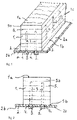
- Figure 1 shows an example of a floor beam according to the invention seen in a perspective view from above.
- Figure 2 shows a cross section through the floor beam in figure 1 .
- the floor beam is intended for use as a load-bearing beam for floors in house buildings and bridge buildings.
- the floor beam comprises an elongate beam 1 of wood having an upper side 1a and a lower side 1b extending in the longitudinal direction of the beam 1 and two opposite long sides 1c which extend between the upper side 1a and the lower side 1b in the longitudinal direction of the beam 1.
- the beam 1 has a rectangular cross section.
- the beam 1 is a glulam beam and comprises a plurality of wooden slats 5 which are stacked along the height of the beam between the lower side 1b and the upper side 1a of the beam.
- the slats 5 are glued together.
- the floor beam comprises a bottom flange 2 of steel fixed to the lower side 1b of the beam 1 and extends along the beam 1 in the longitudinal direction of the beam.
- the bottom flange 2 is fixed to the beam 1 with a plurality of elongate metal fastening elements 3 arranged perpendicular to the longitudinal direction of the beam and spaced apart along the longitudinal direction of the beam 1.
- Each of the fastening elements 3 extends through the entire bottom flange 2 and through the beam 1 to a level which is at least 20% of the distance between the lower side 1b and the upper side 1a of the beam 1.
- the bottom flange 2 projects from the beam 1 on each side of the beam 1 along the long sides so that a projecting part 2a, 2b is formed on each side of the beam 1.
- Each of the projecting parts 2a, 2b of the bottom flange 2 has a width that is at least 20% wider than the distance between the long sides 1c of the beam, i.e. 20% wider than the width of the beam 1.
- the beam 1 is reinforced against shear forces by means of the bottom flange 2 in order to thereby increase the torque capacity in the beam 1.
- the bottom flange 2 is mounted along the entire length of the wooden beam 1.
- the bottom flange 2 has an upper surface abutting the lower side 1b of the beam 1 and a lower surface facing away from the floor beam.
- the bottom flange 2 is made in a width such that the bottom flange 2 is wider than the wooden beam 1 on each side of the beam 1 and so that the bottom flange 2 thereby forms a support on each side of the beam.
- the assembly of the flange 2 can be carried out at the factory where the wooden beam 1 is manufactured or at a workplace.
- the bottom flange can advantageously be provided with pre-drilled holes 4.
- the bottom flange 2 with its pre-drilled holes 4 has been mounted on the lower side 1b of the wooden beam 1 and the fastening elements 3 have been arranged through the pre-drilled holes 4 in the bottom flange 2 and vertically up through the wooden beam 1, the bottom flange 2 and the wooden beam 1 are homogeneously anchored to each other.
- the fastening elements 3 which may be designed as screws with screw heads, are tightened until there is a fixed connection between the lower side 2b of the bottom flange 2 and the beam 1.
- the fastening elements 3 are tightened and when the beam 1 and the bottom flange 2 have been homogeneously connected to each other, a very effective cooperation is archived in the floor beam, which means that the entire beam 1 constitutes the pressure zone in the construction and the bottom flange 2 constitutes the tension zone with low flexibility and small deflections.
- the fastening elements 3 are anchored in the beam 1 together with the flange 2 in a single row along the beam 1, or two rows along the beam, or more than two rows depending on the width of the beam 1 and loads on the beam 1 of the floor beam.
- Figure 2 thus shows a floor beam comprising an elongate wooden beam 1 with a substantially rectangular cross-section, an upper side 1a, a lower side 1b and two opposite longitudinal sides 1c which extend between the upper side 1a and the lower side 1b in the longitudinal direction of the beam 1.
- the beam 1 has been reinforced against shear forces by means of a bottom flange 2 in order to thereby increase the torque capacity in the beam 1.
- the bottom flange 2 is mounted along the lower side 1b of the beam and preferably along the entire length of the beam 1.
- the flange 2 with its pre-drilled holes 4 is mounted on the lower side 1b of the beam with the fastening elements 3 through the pre-drilled holes 4 into the bottom flange 2.
- the fastening elements 3 are tightened until there is a fixed connection between the bottom flange 2 beam 1.
- the beam 1 can be reinforced against the fastening elements 3 by means of an adhesive layer.
- the fastening elements 3 can be mounted in a row along the entire length of the beam 1 as well as two rows and also several rows along the entire length of the beam 1.
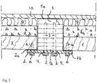
- Figure 3 shows in one section of an area of use for the floor beam described in figure 1 . It is advantage to use the floor beam in the construction of residential buildings.
- a wooden floor layer 7 of wooden boards is arranged on the projecting parts 2a, 2b of the bottom flange 2.
- the wooden floor layer 7 is fixed to the projecting parts 2a, 2b of the beam 1 by means of fasteners, for example screws 6.
- the bottom flange 2 has pre-drilled holes for the screws 6.
- foam concrete 8 is pumped out over the floor layer 7 to a certain thickness.
- the floor layer 7 is so rigid that it makes it possible to pump up foam concrete 8 and level it along the floor layer 7.
- the foam concrete 8 is preferably a concrete with a relatively small bulk density, approx. 350 kg / m3. This concrete is excellent as sound insulation between floor-separating floors. Together with the insulating board 9, the floor together with the floor beam has an excellent sound-insulating effect.
- the foam concrete can also be replaced by an insulating board 9.
- the beam 1 comprises a plurality of wooden slats 5 which are stacked along the height of the beam between the lower side 1b and the upper side 1a and are glued together so that they form a glulam beam. Its width can vary between 100 to 500 mm. Its height can vary between 200 to 1500 mm.
- the bottom flange 2 can be made of untreated steel, painted steel or galvanized steel and also in stainless steel. Its quality can vary between S235 to S900. The width of the bottom flange can vary between 100 to 500 mm.
- the thickness of the bottom flange 2 can vary between 5 and 70 mm, and can preferably vary between 10 and 60 mm.
- the fastening elements 3 can be made of steel or of metal which can be an alloy of different materials with a hardness such as steel and be designed as rebar long steel bars unthreaded or partially threaded or completely threaded such as screws, galvanized or stainless steel.
- the fastening elements 3 are not bound to be made of steel, other metals can be used.
- the fastening elements 3 can be manufactured in different thicknesses from 5 to 30 mm and in lengths 50 to 1200 mm. Glue can be used to anchor the fastening elements. Different types of glue can be used depending on the loads to which the floor beam is subjected.
- the beam 1 comprises a plurality of wooden slats 5 which are stacked along the height of the beam between the lower side 1b and the upper side 1a and are glued together so that the beam 1 constitutes a glulam beam.
- the upper slat 5a or the upper slats are made of a harder type of wood than spruce in which glulam beams are normally made.
- a harder type of wood, such as oak or ash improves the compressive strength of the beam 1.
- the entire beam 1 is made of hardwoods, such as ash or oak.
- the wooden slats 3 comprise cross-laid boards or planks which have been sawn to suitable dimensions and thicknesses.
- the holes 4 and the fastening elements 3 can be evenly distributed along the longitudinal direction of the wooden beam 1 or they are arranged denser at the ends of the wooden beam than at the middle of the wooden beam 1.
- the transverse forces are always greatest at the ends 20, 21.
- the fastening elements 3 in the beam prevent the beam from shearing.
- the fastening elements 3 can thus be more closely placed at the ends.
- the torque forces are crucial at the centre of the beam 1 where the torque and deflections are greatest.
- the ends 20, 21 of the beam 1 are counted as the closest 10-30cm from the ends depending on the total length of the beam.
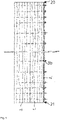
- Figure 4 shows an elevation of a further example of a floor beam where the fastening elements 3 are arranged denser at the ends of the beam 1 than in the middle.
- the ends 20, 21 of the beam 1 rests on two supports.
- the fastening elements 3 which are anchored in the wooden beam 1 and in the bottom flange 2 by tightened nuts 3b are more closely placed against the ends 20 and 21 where the shear forces are greatest.
- the fastening elements 3 effectively prevent the wooden slats 5 of the glulam beam from coming loose from each other when shear forces arise against the supports and thereby prevent the wooden beam 1 from flexing.
- the fastening elements 3 are more sparingly placed against the centre of the beam 1 where the torque forces and deflections are greatest.
- the upper slat 8, or several of the slats 5 is replaced with a harder type of wood, for example ash, instead of spruce as is usual. This improves the compressive strength of the wooden beam 1.
- a longitudinal steel plate is mounted along the entire length of the beam.
- the steel plate has a greater width than the width of the glulam beam.
- the steel plate constitutes the bottom flange 2 of the floor beam.
- the bottom flange 2 is temporarily mounted on the lower side 1b of the glulam beam. This can be done at the factory where the glulam beam is manufactured or at a workplace. After the bottom flange 2 has been mounted, holes are drilled vertically from the lower side 1b of the wooden beam, through the bottom flange 2, up through the slats 3 into the glulam beam and to a pre-desired depth. These holes are drilled vertically up into the beam and along the entire length of the beam in a predetermined pattern.
- the holes are injected with glue 13 and fastening elements in the form of threaded metal rods are pushed in through the holes of the bottom flange and into the glulam beam.
- the holes in the glulam beam must be so narrow that the fastening elements 3 must be pressed in with force.
- nuts are screwed onto the pre-threaded fastening elements. The nuts are tightened with a predetermined torque, after the glue has dried, so that there is an effective interaction between the threaded reinforcement bars, the glulam beam and the bottom flange 2 of steel.
- the task of the nuts is to firmly anchor the bottom flange 2 to the threaded fastening elements.
- the fastening elements 3 will be homogeneously anchored in the glulam beam and together with the longitudinal bottom flange 2 of steel there will be an excellent interaction between the glulam beam, the fastening elements 3 and the bottom flange 2.
- the glulam beam 2 constitute the drag zone.
- the fastening elements 3 which act as shear connectors between the glulam beam and the bottom flange 2 and effectively prevent the shear forces from acting on the glulam beam and its slats 5 and prevents the slats from separating from each other, and at the same time the longitudinal steel bottom flange 2 arranged along the glulam beam, which is dimensioned to absorb all torque in the beam, contribute so that the floor beam can handle all loads, i.e. transverse forces and torque forces without the beam being deformed or break.
Abstract
The present invention relates to a floor beam for use as a load-bearing beam for floors in houses and bridges. The floor beam comprises an elongated beam (1) having an upper side (1a) and a lower side (1b) extending in the longitudinal direction of the beam (1) and two opposite long sides (1c). The beam (1) comprises a plurality of wooden slats (5, 5a) which are stacked along the height of the beam (1) to form a glulam beam, and a bottom flange (2) fixed to the lower side (1b) of the beam (1) and extending along the beam (1) in the longitudinal direction of the beam. The bottom flange (2) being fixed to the beam (1) with a plurality of elongate fastening elements (3). The bottom flange (2) is made of steel and projects from the beam (1) on each side of the beam (1), wherein each of the projecting parts (2a, 2b) of the bottom flange (2) has a width that is at least 20% wider than the distance between the long sides (1c) of the beam, and at least the upper wooden slat (5a) is made of a sort of wood that is harder than spruce.
Description
- The present invention relates to a floor beam for use as a load-bearing beam for floors for house buildings, such as residential and office buildings, and bridges.
- Glulam constructions have been known for over 100 years. The glulam beam consists of glued slats of wood that are joined together with the help of glue and heat and thus form a beam. The fibre direction in the slats runs parallel to the length of the beam. The lamella thickness is about 45 mm. The slats are compressed under heat to give a desired beam, a straight beam or a saddle beam or a curved beam. The beams are used both in house construction, indoors and outdoors and also for bridge construction.
- Another type of glulam construction is cross-glued wood, KL wood, multilayer boards of wooden boards, built up of glued, cross-laid boards. KL wood is a versatile product and is mainly used for interior walls, load-bearing walls and floors. The KL board is an environmentally friendly and recyclable building material and when used correctly, it has a long service life.
- With an increase in construction with wooden structures in house construction, interest has increased to improve the opportunities for increased spans, larger free areas and to be able to build tall residential buildings. A glulam beam is most often used for buildings with visible beams in a floor and for floors for open surfaces.
- The glulam beam can be manufactured in different strength classes. The manufacturing standard for the Swedish market is strength class GL30. Some glulam beams are manufactured by splitting glulam beams in class GL30 and then get strength class GL28.
- Slats are also manufactured in a higher strength class at the lower edge and at the upper edge, where the maximum tensile and compressive stresses occur. In the rest of the cross section, where the stresses are lower, slats in a lower strength class are used. The manufacturing method is called combined glulam and is normally denoted by the letter c.
- Building with wood has become more and more interesting for both property owners and also that for environmental reasons they do not want to use mainly concrete, which has environmental consequences both in the production of cement and also when the finished concrete is transported by car to the workplaces. In Norway, a high-rise building has been built, 85 meters high with a wooden structure and also a high-rise building in Sweden.
- When buildings are erected, especially when apartment buildings are to be built, different principles and building methods are used. The most important and biggest challenge is when constructing buildings in a larger number of floors, to be able to stabilize the buildings so that they are not damaged in facades and floors by both wind loads and floor loads.
- Normally two different methods are used. One method is to build a frame of so-called cells. A building constructed in this way consists of load-bearing exterior walls and load-bearing interior walls as well as load-bearing floors. The load-bearing walls are equally spaced apart.
- After a concrete base slab has been cast, load-bearing outer walls of KL boards are first fitted. Then the load-bearing inner walls are mounted on KL boards with a certain distance from each other. The walls are "stamped, supported" so that they do not fall over. Floors of KL boards are mounted on the top of the walls so that all floors are covered. Then additional load-bearing walls are mounted on the mounted floor and an additional floor is mounted.
- The frame thus consists of load-bearing walls and floors of KL boards. This construction causes problems with handling step noises and air noises between the apartments due to the fact that wood has a poor sound-absorbing ability. To solve these problems, one has to perform complicated detail solutions such as step sound mats, subfloors and several layers of gypsum boards as suspended ceilings. Between the apartments on the same floor, special detail solutions are also needed.
- This method of building is slow and inflexible when it comes to making a floor plan. The load-bearing interior walls that are apartment-separating control what the floor plan should look like. Installations can only be performed between the load-bearing interior walls.
- The stabilization of the building is also complex as a number of screw joints hold walls and floors together. It is also difficult to credit the disc effect. A concrete staircase is necessary to stabilize the entire building. The cell division construction has limitations when it comes to building tall buildings.
- Another type of construction is to have load-bearing wooden pillars in the facade and load-bearing pillars inside the building. Loose glulam beams are mounted between the pillars. Between the glulam beams, load-bearing beams are formed, which form the floor layer. Gypsum boards are screwed to the lower side of the beams, which form the suspended ceiling. Insulation is mounted between the beams, which in this construction constitute sound insulation. A floor and a step sound insulation are screwed on the top.
- This construction with load-bearing columns of glulam and load-bearing beams of glulam also has difficulties in solving the problems of sound insulation between the apartments. It involves complex and detailed design to solve these problems. Even in this case, there are limitations to building tall houses without getting too large dimensions on the pillars. Joining pillars entails extensive detailed constructions of steel to cope with the steps in the joints. Stabilization of the building takes place with the help of horizontal trusses of wood that are mounted in the facade. If there is no space on the facade, these are mounted on the inner walls.
- All the mentioned constructions have the disadvantage that the floors become thick. The floors require installations of both water and drainage pipes as well as electrical installations. In addition, insulation is needed to meet the sound requirements. The floor thickness can be between 500-700 mm.
-
US2601910A shows an example of a wooden beam reinforced with a prestressed reinforcement, such as a metal plate, which is attached to the wooden beam. A disadvantage of using a prestressed reinforcement, which is also mentioned inUS2601910A , is that there is a risk that the beam is bent upwards due to the prestress. To avoid this, the metal plate is screwed to the wooden beam with several screws. If such a wooden beam is used as a floor beam, the floor is laid on top of the floor beam. A disadvantage of this is that the total construction height of the floor together with the floor beam becomes high. -
WO2017/064334A1 disclose a wooden beam intended for arches. The purpose of the beam is to bend it and use it in a curved shape. The beam shown inWO2017/064334A1 is not intended for use as a load-bearing beam for floors in house buildings and bridges. The wooden beam is reinforced with a laminate in soft metal, such as aluminum, which is easy to bend. - The object of the present invention is to provide a floor beam for use as a supporting beam for floors in houses and bridges, which gives a low construction height, i.e. the total construction height of the floor together with the floor beam is low.
- This object is achieved with a floor beam according to
claim 1. - The floor beam comprises an elongate beam having an upper side and a lower side extending in the longitudinal direction of the beam, and a bottom flange fixed to the lower side, of the beam and extending along the beam in the longitudinal direction of the beam and two opposite long sides extending between the upper side and the lower side in the longitudinal direction of the beam. The beam comprises a plurality of wooden slats which are stacked along the height of the beam between the lower side and the upper side and are glued together so that the beam forms a glulam beam. The floor beam comprises a bottom flange of steel fixed to the lower side of the beam, and which extends along the beam in the longitudinal direction of the beam. The bottom flange is fixed to the beam by a plurality of elongate metal fastening elements arranged perpendicular to the longitudinal direction of the beam and spaced apart along the longitudinal direction of the beam, each of the fastening elements extending through the bottom flange and through the beam to a level of at least 20% of the distance between the lower side and the upper side of the beam, i.e., the height of the beam. According to the invention, the bottom flange is made of steel and projects from the beam on both sides of the beam along the long sides, each of the projecting parts of the bottom flange has a width which is at least 20% wider than the distance between the long sides of the beam, and at least the upper wooden slat is made of a sort of wood that is harder than spruce.
- Glulam beams are normally made of spruce. Spruce has a hardness of 1.3 according to the Brinell scale. The upper wooden slat is thus of a sort of wood that is harder than 1.3 according to the Brinell scale, for example oak or ash.
- Tensile forces in the floor beam are absorbed in the bottom flange made of steel and compressive forces are absorbed in the beam of wood. Since at least the upper wooden slat of the beam is made of a sort of wood that is harder 1.3 according to the Brinell scale, the wooden beam can absorb greater compressive forces than if it is made of spruce, from which glulam beams are normally made. Because the bottom flange projects on each side of the beam, the total area of the bottom flange increases, which means that it can absorb greater tensile forces than if it does not project from the long sides. The combination of these features means that the floor beam is able to absorb larger loads and stresses, which makes it possible to reduce the height of the beam, but still cope with the loads and stresses required for use as a load-bearing beam for floors in houses and bridges.
- In addition, the projecting parts of the bottom flange can form a support for the floor, which gives a lower construction height compared to the prestressed beam shown in
US2601910A . Since the floors can be mounted on the bottom flange, the floors are integrated in the height of the floor beam. Thus, the total floor, i.e., the floor beam and the floor, gets a low construction height, which is a great advantage when building tall buildings where there are restrictions on the total height of the building. - The distance between the lower side and the upper side of the beam defines the height of the beam. The distance between the long sides of the beam defines the width of the beam.
- The bottom flange, which preferably has pre-drilled holes, is fixed to the lower side of the wooden beam along the length of the beam by means of a plurality of elongate fastening elements. The fastening elements are preferably made of metal. The elongate fastening elements act as shear connectors between the beam and the bottom flange and prevent shear forces from affecting the beam. At the same time, the longitudinal bottom flange together with the wooden beam will also absorb all the moment force in the floor beam and can handle the load applied to the floor beam and at the same time cope with all transverse forces with the help of the elongate fastening elements without the floor beam deforming or failing.
- According to the invention, the beam has two opposite long sides which extend between the upper and lower sides in the longitudinal direction of the beam, and the bottom flange projects from the beam on each side of the beam along the long sides, and each of the projecting parts of the bottom flange has a width of at least 20 % wider than the distance between the long sides of the beam.
- The advantage of the floor beam having a bottom flange that protrudes from the long sides of the beam on each side of the wooden beam is that these, in addition to the floor beam have a large strength in itself, act as a support for a floor of desired material and dimensions. Since floors can be mounted on the bottom flange, the floors are integrated in the height of the floor beam. Thus, the thickness of the total floor, including the floor beam and floor, has a low construction height, which is a great advantage when building tall buildings when there are restrictions on the total height of a building.
- Another advantage of the floor beam is that the glulam beam together with the bottom flange has a very high torsional rigidity. This construction has great advantages when the floor beam is mounted in a facade of a building when the floor only loads the beam eccentrically on one of the projecting parts of the bottom flange.
- At a vertical load, tensions arise in the wooden beam. Compressive stresses occur in the upper part of the beam and tensile stresses in the lower part of the beam. Between the transition of compressive and tensile stresses, the stresses are zero, i.e. the neutral zone.
- A wooden beam can withstand compressive stresses parallel to the fibers about 25% better than tensile stresses parallel to the fibers. One of the great advantages of the invention is that a steel flange replaces the part of the wooden beam where tensile stresses arise. This is possible as the modulus of elasticity of steel is about 135 times larger than wood. For example, a traditional wooden beam of 1 m high, can be replaced with a floor beam according to the invention with a height of 0.4 m. Thus, a floor using a floor beam floor according to the invention as a load-bearing beam has a much lower construction height than a floor beam made entirely of wood.
- A prerequisite for a wooden beam with a bottom flange of steel to withstand vertical loads is that the fastening elements is made of metal and fasten the bottom flange to the wooden beam and that the fastening elements extend at least 20% up into the wooden beam. A metal fastener that is about 130 times stronger than wood can therefore handle the loads that occur between the wooden beam and the fastening elements.
- When the floor beam will be subjected to vertical loads, the wooden beam will constitute the pressure zone and the bottom flange will form the tension zone. The floor beam then constitutes an extraordinarily strong and moment-rigid beam with small deflections, low flexibility, and small deformations and which can be effectively integrated with the rest of the floor. The floor beam that is integrated in the rest of the floor thus has a very low construction height.
- The reinforced wooden beam thus has an excellent transverse force capacity and a very good torque capacity which gives great strength and small deflections and low flexibility.
- The invention also has great advantages when it comes to reinforcing existing wooden beams in, for example, a roof structure. With heavy snow loads, roof beams may need to be reinforced to prevent falling snow. The shear forces in the roof structure can be decisive and therefore the invention is very useful.
- According to the invention, the beam comprises a plurality of wooden slats which are stacked along the height of the beam between the lower side and the upper side of the beam and are glued together so that the beam comprises a glulam beam. The advantage of using a glulam beam is that it is possible to dimension the floor beam for the loads that arise. The condition for this is to dimension, construct and manufacture a floor beam that combines a bottom flange of steel with a certain thickness and width together with a wooden beam with a certain width and height. The glulam beam has the conditions to obtain the right width and height of the wooden beam. With these possibilities, it is possible to construct a floor beam for all loads that may occur in a wooden structure. The elongate fastening elements act as shear connectors between the glulam beam and the bottom flange and effectively prevent the shear forces from affecting the glulam beam so that the slats do not come apart from each other.
- To further strengthen the glulam beam, at least the upper slat, or the upper slats are made of a sort of wood that is harder than spruce, which glulam beams are normally made of, i.e., a sort of wood which has a hardness that is higher is 1.3 according to the Brinell scale. A harder sort of wood, for example oak or ash, improves the compressive strength of the glulam beam. Spruce has a hardness that is 1.3 according to the Brinell scale.
- Preferably, the entire glulam beam is made of a sort of wood that is harder than 1.3 according to the Brinell scale. Having the same sort of wood in all slats makes it easier to manufacture the glulam beam.
- According to an embodiment of the invention, at least the upper slat is made of a sort of wood which is harder than 2.5 according to the Brinell scale, for example birch, ash or oak. Preferably, the entire glulam beam is made of a sort of wood that is harder than 2.5 according to the Brinell scale.
- According to an embodiment of the invention, at least the upper slat is made of a sort of wood which is harder than 3.0 according to the Brinell scale, for example ash or oak. Ash has a hardness that is 3.4 according to the Brinell scale and oak has a hardness that is 3.5 according to the Brinell scale. Preferably, the entire glulam beam is made of a sort of wood that is harder than 3.5 according to the Brinell scale.
- According to an embodiment of the invention, at least the upper slat is made of oak or ash.
- Preferably, the glulam beam has a rectangular cross section.
- According to an embodiment of the invention, the fastening elements extend through the beam to a level which is at least 30% of the distance between the lower side and upper side of the beam, preferably at least 60% of the distance between the lower side and upper side of the beam, and most preferably at least 90% of the distance between the lower side and upper side of the beam. When the floor beam reaches a high height and thus also the wooden beam, the fastening elements that vertically anchor the bottom flange in the wooden beam should also have a higher height. The higher up in the wooden beam, the better the floor beam can withstand deformations. At high loads on the floor beam, tilted forces arise, approximately 45 degrees from the top of the floor beam towards the ends of the beam. These forces are distributed along the entire length of the beam and are greatest at the ends of the beam. The advantage of the fastening elements extending vertically through the bottom flange and higher up in the wooden beam is that the wooden beam can withstand the skewed forces that arise. The titled forces in the wooden beam are very effectively absorbed by these fastening elements, which are about 135 times stronger than wood. Very effectively, the tilted forces prevent them from deforming and crushing the wooden structure in the wooden beam. Therefore, the invention has great advantages in that the floor beam can be exposed and loaded with large vertical loads without the floor beam being deformed or failing.
- The bottom flange has an upper surface abutting the lower side of the beam, and a lower surface facing away from the floor beam.
- According to an embodiment of the invention, each of the fastening elements comprises a part, such as a screw head or a nut, which are arranged so that they press against the lower surface of the bottom flange so that the bottom flange and beam are homogeneously connected to each other.
- According to an embodiment of the invention, the bottom flange is provided with a plurality of holes spaced apart along the longitudinal direction of the beam and said fastening elements are screws arranged in the holes so that the heads of the screws are anchored to the lower surface of the bottom flange. Between the lower side of the wooden beam and the upper side of the bottom flange, horizontal forces arise when the floor beam is subjected to vertical forces. The greater the spans on the floor beams and the greater the vertical loads that arise, the greater the horizontal forces. To ensure that the bottom flange and the wooden beam do not separate from each other at these horizontal forces, the fastening elements that anchor the bottom flange with the wooden beam preferably is designed with a screw head. The fastening elements anchor the bottom flange to the lower side of the wooden beam. The advantage of the design of fastening elements with a screw head is that it is possible to tighten the fastening elements with the aid of a screwdriver to a predetermined moment so that the bottom flange and the wooden beam are homogeneously anchored to each other and prevent the horizontal forces from affecting the floor beam and the bottom flange separates from each other.
- According to an embodiment of the invention, the screws comprise a threaded part along the entire length of the screws and the screws have a screw head which is adapted to be screwed with a sleeve or Allen sleeve.
- The bottom flange, which preferably has pre-drilled holes, can be fixed to the lower side of the beam along the entire length of the beam by means of screws that are self-drilling. The screws act as shear connectors between the glulam beam and the bottom flange and effectively prevent the shear forces from affecting the glulam beam so that its wooden slats do not come loose from each other. At the same time, the longitudinal bottom flange together with the wooden beam will absorb all the moment force in the floor beam and handle the load applied to the beam and at the same time handle all transverse forces with the help of the self-drilling screws in the beam without deforming or failing the beam.
- The screws are tightened with a predetermined torque so that there is an effective interaction between the self-drilling screws, the wooden beam, and the steel bottom flange. The task of the screws is to strongly anchor the bottom flange to the glulam beam and to prevent the shear forces from deforming the glulam beam. Preferably the self-drilling screws have a length up through the flange and into the wooden beam of which is at least 30% of the distance between the lower side and upper side of the beam, at least 60% of the distance between the lower and upper side of the beam and most preferably 90% of the distance between the lower and upper side of the beam.
- According to an embodiment of the invention, the bottom flange is provided with a plurality of holes spaced apart along the longitudinal direction of the beam, the beam is provided with corresponding holes extending to a level which is at least 20% of the distance between the lower side and the upper side of the beam, and the fastening elements include a plurality of metal rods disposed in the holes, each of the fastening elements being threaded at least at a first end, and threaded to engage the threaded first ends of the fastening elements to secure the first ends of the fastening elements to the bottom flange. Preferably, glue is provided in each of the holes for attaching the fastening elements.
- The floor beam according to the invention is suitable to use for large loads such as a bridge building. The floor beam can be designed so that it can handle loads from vehicles on the bridge. To handle vertical and horizontal loads between the wooden beam and the bottom flange, fastening elements with large dimensions are needed. For this purpose, reinforcement bars can advantageously be used, which are threaded at the end which connects the wooden beam and the bottom flange to each other. The reinforcement bars have such strength that they can withstand large shear forces that occur between the bottom flange and the wooden beam. Another fastening elements that can also be used are fully threaded rods in high-strength steel. The advantage of reinforcement bars and fully threaded bars is, in addition to high strength, coarse dimensions up to 36 mm which is necessary for bridge constructions. To anchor these fastening elements, holes need to be pre-drilled in the wooden beam in the length and thickness that fits the fastening elements. Then glue is injected into the holes, the fastening elements are pushed up through the holes in the bottom flange and up through the pre-drilled holes in the beam to a level so that some of the threaded fastening elements protrude below the bottom flange. After the glue has hardened, a nut is screwed onto the fastening element and tightened with a screwdriver to a certain torque so that the bottom flange and the wooden beam are homogeneously anchored to each other.
- According to an embodiment of the invention, the bottom flange has a thickness between 5 and 70 mm, and preferably between 10 and 60 mm.
- According to an embodiment of the invention, the fastening elements are evenly distributed along the longitudinal direction of the beam.
- According to another embodiment of the invention, the fastening elements are arranged more closely at the ends of the beam than at the center of the beam. The fastening elements in the beam prevent the beam from being pushed, especially at the supports where the wooden beam rests. The fastening elements which may extend up through the wooden beam, along the entire length of the beam, have according to this embodiment a denser placement at the ends of the beam, i.e. at the supports, where the so-called shear forces between the beam and the bottom flange are greatest. The torque forces are crucial at the center of the beam where the torque and deflections are greatest.
- According to an embodiment of the invention, the bottom flange covers at least 80% of the surface of the lower side of the beam.
- The invention makes it possible to significantly improve the possibilities of building residential buildings and office buildings, by integrating a floor beam into a floor layer. The floor beam is a storehouse for floors in the facade and inside the building. It is thus possible to build a column deck construction without load-bearing outer walls or load-bearing inner walls. It also makes it possible to significantly improve the sound insulation between the stores and simplify the detailed constructions.
- The floor beam according to the invention is very suitable for house construction. The invention makes it possible to considerably increase the spans of floors and thereby obtain larger free surfaces. The floor beam together with the floor layer also makes it possible to stabilize a multi-storey building with so-called disc effect.
- To further strengthen and ensure that the shear forces do not affect the glulam beam, the lower edge of the glulam beam can be reinforced with steel sleeves where the fastening elements are pressed into the drilled holes with injected glue. The steel sleeve, which forms a steel reinforcement around the lower edge of the hole, prevents the holes in the glulam beam from being deformed by bearing stresses between the glulam beam and the fastening element when the glulam beam is loaded with a vertical load.
- The invention will now be explained in more detail by describing examples of the invention and with reference to the accompanying drawings.
-
Figure 1 shows an example of a floor beam according to the invention seen in a perspective view from above. -
Figure 2 shows a cross section through the floor beam infigure 1 . -
Figure 3 shows a section of an area of use for the floor beam. -
Figure 4 shows a further example of a floor beam where the fastening elements are arranged denser at the ends of the beam than in the middle. - The patent application describes a solution which involves manufacturing a floor beam from a wooden beam reinforced with a steel bottom flange to have a cooperating construction and thereby increase torque capacity and its shear capacity in the floor beam. The purpose of the floor beam is to obtain, together with a wooden floor mounted on the flange of the beam, a floor construction with a low construction height. The floor beam can be manufactured, for example, by drilling pre-drilled holes in a flange, which has the same length as the wooden beam, and then fastening it with fastening elements to the lower side of the wooden beam. The fastening elements are designed so that they strongly anchor the flange to the lower side of the wooden beam so that a complete interaction between the wooden beam and the flange occurs. The fastening elements are, for example, made of steel or also an alloy of different materials to obtain a hardness such as steel, for example bronze which is an alloy of copper and tin. When shear forces occur in the wooden beam together with the bottom flange, shear forces arise between the wooden beam and the bottom flange. The greatest shear forces occur at the ends of the beam and its supports. The fastening elements are, for example, designed so that they have a head which is pressed against the lower side of the flange so that the flange and wooden beam are homogeneously connected to each other. After the fastening elements have been tightened, the shear capacity of the floor beam is also improved. To further improve the interaction of the fastening elements with the wooden beam, glue can be applied to the fastening elements.
-
Figure 1 shows an example of a floor beam according to the invention seen in a perspective view from above.Figure 2 shows a cross section through the floor beam infigure 1 . The floor beam is intended for use as a load-bearing beam for floors in house buildings and bridge buildings. The floor beam comprises anelongate beam 1 of wood having an upper side 1a and a lower side 1b extending in the longitudinal direction of thebeam 1 and two oppositelong sides 1c which extend between the upper side 1a and the lower side 1b in the longitudinal direction of thebeam 1. Preferably, thebeam 1 has a rectangular cross section. - The
beam 1 is a glulam beam and comprises a plurality ofwooden slats 5 which are stacked along the height of the beam between the lower side 1b and the upper side 1a of the beam. Theslats 5 are glued together. The floor beam comprises abottom flange 2 of steel fixed to the lower side 1b of thebeam 1 and extends along thebeam 1 in the longitudinal direction of the beam. Thebottom flange 2 is fixed to thebeam 1 with a plurality of elongatemetal fastening elements 3 arranged perpendicular to the longitudinal direction of the beam and spaced apart along the longitudinal direction of thebeam 1. Each of thefastening elements 3 extends through the entirebottom flange 2 and through thebeam 1 to a level which is at least 20% of the distance between the lower side 1b and the upper side 1a of thebeam 1. Thebottom flange 2 projects from thebeam 1 on each side of thebeam 1 along the long sides so that a projectingpart 2a, 2b is formed on each side of thebeam 1. Each of the projectingparts 2a, 2b of thebottom flange 2 has a width that is at least 20% wider than the distance between thelong sides 1c of the beam, i.e. 20% wider than the width of thebeam 1. - The
beam 1 is reinforced against shear forces by means of thebottom flange 2 in order to thereby increase the torque capacity in thebeam 1. Preferably, thebottom flange 2 is mounted along the entire length of thewooden beam 1. Thebottom flange 2 has an upper surface abutting the lower side 1b of thebeam 1 and a lower surface facing away from the floor beam. Thebottom flange 2 is made in a width such that thebottom flange 2 is wider than thewooden beam 1 on each side of thebeam 1 and so that thebottom flange 2 thereby forms a support on each side of the beam. The assembly of theflange 2 can be carried out at the factory where thewooden beam 1 is manufactured or at a workplace. The bottom flange can advantageously be provided withpre-drilled holes 4. After thebottom flange 2 with itspre-drilled holes 4 has been mounted on the lower side 1b of thewooden beam 1 and thefastening elements 3 have been arranged through thepre-drilled holes 4 in thebottom flange 2 and vertically up through thewooden beam 1, thebottom flange 2 and thewooden beam 1 are homogeneously anchored to each other. - The
fastening elements 3, which may be designed as screws with screw heads, are tightened until there is a fixed connection between the lower side 2b of thebottom flange 2 and thebeam 1. When thefastening elements 3 are tightened and when thebeam 1 and thebottom flange 2 have been homogeneously connected to each other, a very effective cooperation is archived in the floor beam, which means that theentire beam 1 constitutes the pressure zone in the construction and thebottom flange 2 constitutes the tension zone with low flexibility and small deflections. - When the
beam 1 is subjected to vertical loads, shear forces arise in thefastening elements 3 which very effectively prevent thebeam 1 from deforming or cracking. At the same time, thelongitudinal flange 2 will also provide an excellent torque capacity together with thebeam 1. Thefastening elements 3 are anchored in thebeam 1 together with theflange 2 in a single row along thebeam 1, or two rows along the beam, or more than two rows depending on the width of thebeam 1 and loads on thebeam 1 of the floor beam. -
Figure 2 thus shows a floor beam comprising an elongatewooden beam 1 with a substantially rectangular cross-section, an upper side 1a, a lower side 1b and two oppositelongitudinal sides 1c which extend between the upper side 1a and the lower side 1b in the longitudinal direction of thebeam 1. Thebeam 1 has been reinforced against shear forces by means of abottom flange 2 in order to thereby increase the torque capacity in thebeam 1. Thebottom flange 2 is mounted along the lower side 1b of the beam and preferably along the entire length of thebeam 1. Theflange 2 with itspre-drilled holes 4 is mounted on the lower side 1b of the beam with thefastening elements 3 through thepre-drilled holes 4 into thebottom flange 2. Thefastening elements 3 are tightened until there is a fixed connection between thebottom flange 2beam 1. When thefastening elements 3 are tightened and when thebeam 1 and thebottom flange 2 have been homogeneously connected to each other, a very effective cooperation occurs in the floor beam, which means that thebeam 1 and thebottom flange 2 constitute the tension zone with low flexibility and small deflections. Thebeam 1 can be reinforced against thefastening elements 3 by means of an adhesive layer. Thefastening elements 3 can be mounted in a row along the entire length of thebeam 1 as well as two rows and also several rows along the entire length of thebeam 1. -
Figure 3 shows in one section of an area of use for the floor beam described infigure 1 . It is advantage to use the floor beam in the construction of residential buildings. Awooden floor layer 7 of wooden boards is arranged on the projectingparts 2a, 2b of thebottom flange 2. Thewooden floor layer 7 is fixed to the projectingparts 2a, 2b of thebeam 1 by means of fasteners, for example screws 6. Thebottom flange 2 has pre-drilled holes for thescrews 6. After thefloor layer 7 has been mounted on the two projectingparts 2a, 2b of thebottom flange 2, foam concrete 8 is pumped out over thefloor layer 7 to a certain thickness. Thefloor layer 7 is so rigid that it makes it possible to pump up foam concrete 8 and level it along thefloor layer 7. After the foam concrete 8 has hardened, an insulating board 9 is laid on the concrete and then atop floor 10 is mounted. Thescrews 6 can be galvanized or stainless in dimensions 8 to 16 mm and lengths between 50 to 150 mm. The foam concrete 8 is preferably a concrete with a relatively small bulk density, approx. 350 kg / m3. This concrete is excellent as sound insulation between floor-separating floors. Together with the insulating board 9, the floor together with the floor beam has an excellent sound-insulating effect. The foam concrete can also be replaced by an insulating board 9. - Here is mentioned material properties on the
bottom flange 2, thebeam 1, and the fastening elements3 and suitable dimensions without thereby constituting any limitations. Thebeam 1 comprises a plurality ofwooden slats 5 which are stacked along the height of the beam between the lower side 1b and the upper side 1a and are glued together so that they form a glulam beam. Its width can vary between 100 to 500 mm. Its height can vary between 200 to 1500 mm. Thebottom flange 2 can be made of untreated steel, painted steel or galvanized steel and also in stainless steel. Its quality can vary between S235 to S900. The width of the bottom flange can vary between 100 to 500 mm. The thickness of thebottom flange 2 can vary between 5 and 70 mm, and can preferably vary between 10 and 60 mm. Thefastening elements 3 can be made of steel or of metal which can be an alloy of different materials with a hardness such as steel and be designed as rebar long steel bars unthreaded or partially threaded or completely threaded such as screws, galvanized or stainless steel. Thefastening elements 3 are not bound to be made of steel, other metals can be used. Thefastening elements 3 can be manufactured in different thicknesses from 5 to 30 mm and in lengths 50 to 1200 mm. Glue can be used to anchor the fastening elements. Different types of glue can be used depending on the loads to which the floor beam is subjected. - In the illustrated example, the
beam 1 comprises a plurality ofwooden slats 5 which are stacked along the height of the beam between the lower side 1b and the upper side 1a and are glued together so that thebeam 1 constitutes a glulam beam. To further strengthen thebeam 1, theupper slat 5a or the upper slats are made of a harder type of wood than spruce in which glulam beams are normally made. A harder type of wood, such as oak or ash, improves the compressive strength of thebeam 1. It is also possible that theentire beam 1 is made of hardwoods, such as ash or oak. In the case that theglulam beam 1 comprises KL wood, thewooden slats 3 comprise cross-laid boards or planks which have been sawn to suitable dimensions and thicknesses. - The
holes 4 and thefastening elements 3 can be evenly distributed along the longitudinal direction of thewooden beam 1 or they are arranged denser at the ends of the wooden beam than at the middle of thewooden beam 1. The transverse forces are always greatest at theends fastening elements 3 in the beam prevent the beam from shearing. Thefastening elements 3 can thus be more closely placed at the ends. The torque forces are crucial at the centre of thebeam 1 where the torque and deflections are greatest. The ends 20, 21 of thebeam 1 are counted as the closest 10-30cm from the ends depending on the total length of the beam. -
Figure 4 shows an elevation of a further example of a floor beam where thefastening elements 3 are arranged denser at the ends of thebeam 1 than in the middle. The ends 20, 21 of thebeam 1 rests on two supports. Thefastening elements 3 which are anchored in thewooden beam 1 and in thebottom flange 2 by tightened nuts 3b are more closely placed against theends wooden beam 1, thefastening elements 3 effectively prevent thewooden slats 5 of the glulam beam from coming loose from each other when shear forces arise against the supports and thereby prevent thewooden beam 1 from flexing. In this embodiment, thefastening elements 3 are more sparingly placed against the centre of thebeam 1 where the torque forces and deflections are greatest. - To further strengthen the
wooden beam 1, to enable lower construction height on thewooden beam 1, the upper slat 8, or several of theslats 5, is replaced with a harder type of wood, for example ash, instead of spruce as is usual. This improves the compressive strength of thewooden beam 1. - Below is described an example of a floor beam and how to assemble it.
- On the lower side 1b of a glulam beam, a longitudinal steel plate is mounted along the entire length of the beam. The steel plate has a greater width than the width of the glulam beam. The steel plate constitutes the
bottom flange 2 of the floor beam. - The
bottom flange 2 is temporarily mounted on the lower side 1b of the glulam beam. This can be done at the factory where the glulam beam is manufactured or at a workplace. After thebottom flange 2 has been mounted, holes are drilled vertically from the lower side 1b of the wooden beam, through thebottom flange 2, up through theslats 3 into the glulam beam and to a pre-desired depth. These holes are drilled vertically up into the beam and along the entire length of the beam in a predetermined pattern. - After drilling has taken place vertically in the glulam beam from the lower side 1b of the wooden beam along the entire length of the beam, the holes are injected with glue 13 and fastening elements in the form of threaded metal rods are pushed in through the holes of the bottom flange and into the glulam beam. The holes in the glulam beam must be so narrow that the
fastening elements 3 must be pressed in with force. After the glue has dried, nuts are screwed onto the pre-threaded fastening elements. The nuts are tightened with a predetermined torque, after the glue has dried, so that there is an effective interaction between the threaded reinforcement bars, the glulam beam and thebottom flange 2 of steel. The task of the nuts is to firmly anchor thebottom flange 2 to the threaded fastening elements. - The
fastening elements 3 will be homogeneously anchored in the glulam beam and together with thelongitudinal bottom flange 2 of steel there will be an excellent interaction between the glulam beam, thefastening elements 3 and thebottom flange 2. When the glulam beam will subsequently be subjected to vertical loads, theglulam beam 2 constitute the drag zone. - The
fastening elements 3 which act as shear connectors between the glulam beam and thebottom flange 2 and effectively prevent the shear forces from acting on the glulam beam and itsslats 5 and prevents the slats from separating from each other, and at the same time the longitudinalsteel bottom flange 2 arranged along the glulam beam, which is dimensioned to absorb all torque in the beam, contribute so that the floor beam can handle all loads, i.e. transverse forces and torque forces without the beam being deformed or break. -
- 1 beam
- 1a upper side of the beam
- 1b lower side of the beam
- 1c long sides of the beam
- 2 bottom flange
- 2a, 2b projecting parts of the bottom flange
- 3 fastening elements
- 3b nuts
- 4 holes
- 5 wooden slats
- 5a upper slat
- 6 screws
- 7 load bearing floor
- 8 foam concrete
- 9 insulating board
- 10 top floor
- 20, 21 ends of the beam
Claims (8)
- Floor beam for use as a load-bearing beam for floors in houses and bridges, wherein the floor beam comprises an elongated beam (1) having an upper side (1a) and a lower side (1b) extending in the longitudinal direction of the beam (1) and two opposite long sides (1c) which extend between the upper side (1a) and the lower side (1b) in the longitudinal direction of the beam, the beam (1) comprises a plurality of wooden slats (5, 5a) which are stacked along the height of the beam (1) between the lower side (1b) and the upper side (1a) and are glued together to form a glulam beam, and a bottom flange (2) fixed to the lower side (1b) of the beam (1) and extending along the beam (1) in the longitudinal direction of the beam, the bottom flange (2) being fixed to the beam (1) with a plurality of elongate fastening elements (3) made of metal arranged perpendicular to the longitudinal direction of the beam (1) and at a distance from each other along the longitudinal direction of the beam, each of the fastening elements (3) extending through the entire bottom flange (2) and through the beam (1) to a level of at least 20% of the distance between the lower side (1b) and the upper side (1a) of the beam, characterized in that the bottom flange (2) is made of steel and projects from the beam (1) on each side of the beam (1) along the long sides (1c), wherein each of the projecting parts (2a, 2b) of the bottom flange (2) has a width that is at least 20% wider than the distance between the long sides (1c) of the beam, and at least the upper wooden slat (5a) is made of a sort of wood that is harder than spruce.
- The floor beam according to claim 1, wherein at least the upper wooden slat (5a) is of a sort of wood which is harder than 2.5 according to the Brinell scale.
- The floor beam according to claim 1, wherein at least the upper wooden slat (5a) is of a sort of wood which is harder than 3.0 according to the Brinell scale.
- The floor beam according to any one of the preceding claims, wherein the fastening elements (3) extend through the beam (1) to a level which is at least 30% of the distance between the lower side (1b) and the upper side (1a) of the beam (1), preferably at least 60% of the distance between the lower side (1b) and the upper side (1a) of the beam, and most preferably at least 90% of the distance between the lower side (1b) and the upper side (1a) of the beam.
- The floor beam according to any one of the preceding claims, wherein the fastening elements (3) are arranged denser at the ends of the beam (1) than at the centre of the beam (1).
- Floor beam according to any one of the preceding claims, wherein the bottom flange (2) has an upper surface which abuts against the lower side (1b) of the beam, and a lower surface, the bottom flange (2) is provided with a plurality of holes (4 ) arranged at a distance from each other along the longitudinal direction of the beam, and said fastening elements (3) are screws arranged in the holes (4) so that the heads of the screws (3) are anchored to the lower surface of the bottom flange (2).
- The floor beam according to any one of the preceding claims, wherein the bottom flange (2) has a thickness between 5 and 70 mm, and preferably between 10 and 60 mm.
- The floor beam according to any one of the preceding claims, wherein the beam (1) has a rectangular cross-section.
Applications Claiming Priority (1)
| Application Number | Priority Date | Filing Date | Title |
|---|---|---|---|
| SE2150463A SE2150463A1 (en) | 2021-04-15 | 2021-04-15 | Integrated wooden and steel floor beam |
Publications (1)
| Publication Number | Publication Date |
|---|---|
| EP4074912A1 true EP4074912A1 (en) | 2022-10-19 |
Family
ID=81127163
Family Applications (1)
| Application Number | Title | Priority Date | Filing Date |
|---|---|---|---|
| EP22167739.6A Withdrawn EP4074912A1 (en) | 2021-04-15 | 2022-04-12 | Floor beam for buildings and bridges |
Country Status (2)
| Country | Link |
|---|---|
| EP (1) | EP4074912A1 (en) |
| SE (1) | SE2150463A1 (en) |
Citations (6)
| Publication number | Priority date | Publication date | Assignee | Title |
|---|---|---|---|---|
| US2601910A (en) | 1944-05-16 | 1952-07-01 | Thomas F Nichols | Composite structural member |
| WO1986000362A1 (en) * | 1984-06-22 | 1986-01-16 | Arne Engebretsen | Devices for load carrying structures |
| RU2022109C1 (en) * | 1991-07-16 | 1994-10-30 | Воронежский инженерно-строительный институт | Wooden gluing beam |
| WO2017064334A1 (en) | 2015-10-13 | 2017-04-20 | Aldea Sophia, Sl | Reinforced laminated beam and method for the production thereof |
| CN108532828A (en) * | 2018-03-10 | 2018-09-14 | 中南林业科技大学 | A kind of steel and wood composite structural beams |
| RU190912U1 (en) * | 2019-04-26 | 2019-07-16 | Федеральное государственное бюджетное образовательное учреждение высшего образования "Казанский государственный архитектурно-строительный университет" (КазГАСУ) | STEEL CONCRETE BOOSTER BEAM |
Family Cites Families (1)
| Publication number | Priority date | Publication date | Assignee | Title |
|---|---|---|---|---|
| JP2000289008A (en) * | 1999-04-09 | 2000-10-17 | Noboru Watanabe | Steel stiffened wood girder |
-
2021
- 2021-04-15 SE SE2150463A patent/SE2150463A1/en unknown
-
2022
- 2022-04-12 EP EP22167739.6A patent/EP4074912A1/en not_active Withdrawn
Patent Citations (6)
| Publication number | Priority date | Publication date | Assignee | Title |
|---|---|---|---|---|
| US2601910A (en) | 1944-05-16 | 1952-07-01 | Thomas F Nichols | Composite structural member |
| WO1986000362A1 (en) * | 1984-06-22 | 1986-01-16 | Arne Engebretsen | Devices for load carrying structures |
| RU2022109C1 (en) * | 1991-07-16 | 1994-10-30 | Воронежский инженерно-строительный институт | Wooden gluing beam |
| WO2017064334A1 (en) | 2015-10-13 | 2017-04-20 | Aldea Sophia, Sl | Reinforced laminated beam and method for the production thereof |
| CN108532828A (en) * | 2018-03-10 | 2018-09-14 | 中南林业科技大学 | A kind of steel and wood composite structural beams |
| RU190912U1 (en) * | 2019-04-26 | 2019-07-16 | Федеральное государственное бюджетное образовательное учреждение высшего образования "Казанский государственный архитектурно-строительный университет" (КазГАСУ) | STEEL CONCRETE BOOSTER BEAM |
Also Published As
| Publication number | Publication date |
|---|---|
| SE544344C2 (en) | 2022-04-12 |
| SE2150463A1 (en) | 2022-04-12 |
Similar Documents
| Publication | Publication Date | Title |
|---|---|---|
| CA2692723C (en) | Structural insulated roof panels with a rigid foam core | |
| US8109055B2 (en) | Building panel with a rigid foam core, stud channels, and without thermal bridging | |
| US7549263B1 (en) | Structural insulated panel with hold down chase | |
| US20060117689A1 (en) | Apparatus, system and method of manufacture thereof for insulated structural panels comprising a combination of structural metal channels and rigid foam insulation | |
| US8782993B2 (en) | Structural unit comprising a truss and fibrous cementitious slab building element connected together | |
| US11060273B2 (en) | Laminated bamboo platform and concrete composite slab system | |
| CN108797889B (en) | Steel-wood composite beam structure and construction method thereof | |
| CN106592825A (en) | Assembly type wood frame energy-saving shear wall | |
| EP4074912A1 (en) | Floor beam for buildings and bridges | |
| AU2021200695B2 (en) | Composite Timber Components | |
| JP2016169565A (en) | In-plane shear bearing force structure, and roof structure, wall structure and floor structure having in-plane shear bearing force structure | |
| CN116940463A (en) | Bamboo building element | |
| EP1811097B1 (en) | Building element | |
| EP0675990B1 (en) | Building unit, preferably for roofing structures, and a method of manufacturing it | |
| JP2020165174A (en) | Floor panel for wooden building | |
| RU200790U1 (en) | Overlap | |
| US20060265998A1 (en) | Method for preparing a floor | |
| EP1953300B1 (en) | Arrangement for joining wood-based construction elements | |
| McKinley | The Canadian Wood Council (CWC) is Canada’s authoritative source of technical information and tools for wood design and construction. Wood construction in mid-rise residential and non-residential buildings is booming, and provisions in the 2020 National Building Code are opening new opportunities for taller mass timber construction. Many innovative construction | |
| JP4374075B1 (en) | Wall fixtures and building wall structures | |
| JP2021156096A (en) | Floor framing structure for wooden building | |
| CA2381526A1 (en) | Shear wall panel | |
| JP2021055313A (en) | Log wall structure | |
| Lam et al. | Multi-storey houses in timber-Stability and anchoring systems | |
| AU2017202535A1 (en) | Floor slab support beam and supporting structure |
Legal Events
| Date | Code | Title | Description |
|---|---|---|---|
| PUAI | Public reference made under article 153(3) epc to a published international application that has entered the european phase |
Free format text: ORIGINAL CODE: 0009012 |
|
| STAA | Information on the status of an ep patent application or granted ep patent |
Free format text: STATUS: THE APPLICATION HAS BEEN PUBLISHED |
|
| AK | Designated contracting states |
Kind code of ref document: A1 Designated state(s): AL AT BE BG CH CY CZ DE DK EE ES FI FR GB GR HR HU IE IS IT LI LT LU LV MC MK MT NL NO PL PT RO RS SE SI SK SM TR |
|
| STAA | Information on the status of an ep patent application or granted ep patent |
Free format text: STATUS: THE APPLICATION IS DEEMED TO BE WITHDRAWN |
|
| 18D | Application deemed to be withdrawn |
Effective date: 20230420 |