EP4074881A1 - Laundry treatment appliance with water softening system - Google Patents
Laundry treatment appliance with water softening system Download PDFInfo
- Publication number
- EP4074881A1 EP4074881A1 EP21168654.8A EP21168654A EP4074881A1 EP 4074881 A1 EP4074881 A1 EP 4074881A1 EP 21168654 A EP21168654 A EP 21168654A EP 4074881 A1 EP4074881 A1 EP 4074881A1
- Authority
- EP
- European Patent Office
- Prior art keywords
- water
- softening agent
- water softening
- agent container
- container
- Prior art date
- Legal status (The legal status is an assumption and is not a legal conclusion. Google has not performed a legal analysis and makes no representation as to the accuracy of the status listed.)
- Granted
Links
Images

Classifications
-
- D—TEXTILES; PAPER
- D06—TREATMENT OF TEXTILES OR THE LIKE; LAUNDERING; FLEXIBLE MATERIALS NOT OTHERWISE PROVIDED FOR
- D06F—LAUNDERING, DRYING, IRONING, PRESSING OR FOLDING TEXTILE ARTICLES
- D06F39/00—Details of washing machines not specific to a single type of machines covered by groups D06F9/00 - D06F27/00
- D06F39/007—Arrangements of water softeners
Definitions
- the present invention generally relates to the field of laundry treatment appliances (hereinafter, concisely, “laundry appliances”), and particularly to laundry appliances for treating, e.g . washing, laundry, such as laundry washing appliances and laundry washing appliances also implementing laundry drying functions (also referred to as washers/dryers).
- laundry appliances for treating, e.g . washing, laundry, such as laundry washing appliances and laundry washing appliances also implementing laundry drying functions (also referred to as washers/dryers).
- Laundry appliances are configured to treat laundry located in a (e.g., rotatable) drum by providing process water in a washing tub housing the rotatable drum.
- process water it is generally intended plain water or water mixed with proper (e.g ., liquid and powder) treatment agents, including, but not limited to, washing detergents, rinsing detergents, bleaches and softeners detergents, softeners, bleaches, dyes.
- proper e.g ., liquid and powder
- treatment agents including, but not limited to, washing detergents, rinsing detergents, bleaches and softeners detergents, softeners, bleaches, dyes.
- the hardness of the water may negatively affect the performance of a laundry appliance. Indeed, laundry treated using excessively hard water may require higher temperatures, and even if high temperatures are used, the result of the laundry treatment can be not satisfactory. Moreover, laundry treated using hard water may become stiff, subjected to premature tear and wear, and cause skin irritation. In addition, the parts of the laundry appliance that are in direct contact with water (e.g., ducts, tanks, valves, heater resistors) may become encrusted with limestone, impairing the correct operation of the laundry appliance.
- water e.g., ducts, tanks, valves, heater resistors
- a water softening system comprises a container containing a water softening agent (e.g., a ion-exchange resin) capable of reducing hardness of water by promoting exchange of the minerals dissolved in water causing hardness (e.g ., calcium and magnesium) for a soft mineral that does not build up on surfaces, such as sodium.
- a water softening agent e.g., a ion-exchange resin
- the water softening agent After several uses, the water softening agent get exhausted, strongly reducing the water softening performances.
- the water softening system further comprises a (refillable) container for storing a regenerating agent, usually salt, to be used for regenerating the exhausted softening agent during a water softening agent regeneration procedure.
- the water softening system is provided at the drawer of the laundry appliance where compartments for containing the treatment agents are located, for example directly integrated in the drawer itself and/or in a drawer seat of the laundry appliance for slidably housing the drawer.
- EP0190675 discloses a washing machine having a detergent supply box and a water softening device.
- the water softening device comprises a softening part, a replenishable salt container and a water chamber, which is to be filled with fresh water and has a means for preventing back-flow incorporated therein, which means is connected upstream of the softening part.
- the softening part and the salt container are disposed in a lower region of the machine and are connected to the water chamber, situated thereabove, by means of pipes in that the soft water outlet of the softening part is connected to the detergent supply box, situated in an upper portion of the machine, by means of a pipe, and in that a branch is fitted in this connection pipe and a pipe extends from said branch to the discharge system of the washing machine.
- a drawback affecting the solution in which the water softening system is provided at the drawer of the laundry appliance is the scarce space available for the water softening agent container and the salt container. Because of that, a user of the laundry appliance is disadvantageously forced to refill the salt container with new salt with a relatively high frequency.
- the solution provided in EP1960675 provides that fresh water provided from an external water supply is stored in a water chamber before being supplied to the softening part for reducing the hardness thereof. Directly storing - possibly hard - fresh water coming from an external water supply in a water chamber is not efficient because it may cause the formation of limestone on the walls of the water chamber, capable of impairing the correct operation of the laundry appliance.
- the Applicant has devised a solution for implementing a water softening system for a laundry appliance that is not affected by the abovementioned drawbacks.
- an aspect of the present invention relates to a laundry treatment appliance comprising:
- the process water fed into the washing tub used for treating laundry advantageously comprises soft water.
- the proposed laundry treatment appliance comprises a water softening system arranged in such a way that water is softened just after it reaches the laundry treatment appliance through the water inlet. Indeed, since the water tank is fluidly coupled downstream the water softening agent container, the water softening agent container only stores soft water.
- the peculiar arrangement of the water softening agent container and of the water tank with respect to each other and also with respect to the water inlet are such to reduce the number of components of the laundry treatment appliance that can be in contact with hard water. In this way, formation of limestone on laundry appliance components (such as on the walls of the water tank) that can potentially impair the correct operation of the laundry appliance are avoided or at least strongly reduced.
- the laundry treatment appliance further comprises a container for storing a regenerating agent, preferably salt.
- the salt container is configured to be selectively in fluid communication with a second output of the water tank for receiving soft water.
- the water softening agent container, the water tank and/or the salt container are located on or close to a bottom of the laundry treatment appliance.
- the water softening agent container is located on the bottom at a rear portion of the laundry treatment appliance, the salt container is located on the bottom at a front portion of the laundry treatment appliance, and the water tank is located above the water softening agent container.
- said container for storing salt comprises an output fluidly connected to a second input of the water softening agent container to provide brine to the water softening agent container during a water softening agent regeneration procedure for regenerating said water softening agent.
- said brine comprises soft water received from the soft water tank mixed with stored salt.
- the water softening agent container is configured to be selectively in fluid communication with a drain of the laundry treatment appliance for allowing brine mixed with residuals of the water softening agent regeneration contained in the water softening agent container to be discharged into the drain.
- the brine mixed with residuals of the water softening agent regeneration, before reaching the drain can be advantageously filtered by a drain filter element located upstream the drain, so that anti-pollution standards can be respected.
- the water softening system further comprises a soft water tank valve at the second output of the soft water tank configured to be selectively opened during said water softening agent regeneration procedure for selectively causing soft water stored in the soft water tank flow into the salt container thus generating said brine.
- the water softening system further comprises a pump device configured to be selectively activated during said water softening agent regeneration procedure for selectively causing brine generated in said salt container be pumped in the water softening agent container through the second input thereof.
- the water softening system further comprises a water softening agent container valve arranged at the output of the water softening agent container.
- said water softening agent container valve is configured to be switched between a first operating mode and a second operating mode.
- the output of the water softening agent container is in fluid communication with the input of the water tank.
- the output of the water softening agent container is in fluid communication with said drain of the laundry treatment appliance for allowing brine mixed with residuals of the water softening agent regeneration in the water softening agent container reach said laundry treatment appliance drain.
- the output of the water softening agent container is in fluid communication with said drain of the laundry treatment appliance through the washing tub for allowing brine mixed with residuals of the water softening agent regeneration in the water softening agent container reach said laundry treatment appliance drain.
- the water softening agent container valve is configured to be switched in the second operating mode during or after said water softening agent regeneration procedure.
- said water softening agent container valve is further configured to be switched in a third operating mode in which fluid communication between the output of the water softening agent container and the input of the water tank, and fluid communication between the output of the water softening agent container and the drain of the laundry treatment appliance are prevented.
- the laundry treatment appliance further comprises a first duct for allowing fluid communication between the water softening agent container and the drain when the water softening agent container valve is in the second operating mode.
- said water tank is formed in a single piece with said first duct.
- the laundry treatment appliance further comprises a second duct for allowing fluid communication between the water inlet and the first input of the water softening agent container.
- said water tank is formed in a single piece with said first duct and with said second duct.
- said pump device is configured to be temporally deactivated for a predetermined time for allowing brine contained in the water softening agent container to regenerate said water softening agent.
- the pump device is configured to be reactivated once said water softening agent container valve is in the second operating mode to pump brine mixed with residuals of the water softening agent regeneration in the water softening agent container towards said laundry treatment appliance drain.
- the salt container comprises an air vent duct configured to allow air inside the salt container exit the salt container by a pressure of soft water coming into the salt container from the water tank.
- the salt container can be filled with soft water in an efficient way, avoiding or at least strongly reducing the formation of undesired air bubbles trapped inside the salt container.
- said water softening agent comprises an ion exchange resin.
- said salt container is a refillable salt container adapted to be refilled with amounts of salt.
- said process water deliver apparatus comprises at least one compartment adapted to contain a treatment agent for laundry treatment, and is configured to mix soft water supplied by said soft water tank with said treatment agent.
- the process water fed into the washing tub used for treating laundry may advantageously comprise soft water mixed with treatment agent.
- said laundry treatment appliance is a laundry washing machine or a laundry washing and drying machine.
- Another aspect of the present invention relates to a method for operating a laundry treatment appliance.
- the method comprises:
- the method further comprises, during a water softening agent regeneration procedure for regenerating said water softening agent:
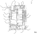
- Figure 1 is a, partially transparent, side view of a laundry appliance 100 according to an embodiment of the present invention.
- the laundry appliance 100 is a washing machine.
- a washing machine this should not to be construed as a limitation; indeed, the present invention applies to other types of laundry appliances (for example combined washers/dryers, i.e. washing machines also having laundry drying functions).
- the laundry appliance 100 comprises a (e.g., parallepiped-shaped) cabinet 105, which preferably accommodates a washing tub 110.
- the washing tub 110 houses a rotatable drum (not shown in the figures) adapted to receive laundry to be treated (e.g., to be washed).
- a cabinet front surface has a loading opening 115 providing an access to the drum for loading/unloading the laundry, a door 120 (shown in a closed position in Figure 1 ) being provided for sealable closing the loading opening 115 during the operation of the laundry appliance 100.
- the laundry appliance 100 comprises a water inlet 122 - for example located on a top portion of a back side of the cabinet 105 - configured to receive water from an external water supply.
- the laundry appliance 100 comprises an apparatus 125 for supplying process water into the washing tub 110.
- the apparatus 125 for supplying process water comprises a drawer 130 having compartments (not visible in Figure 1 ) for containing one or more treatment agents - such as liquid and powder treatment agents including, but not limited to, washing detergents, rinsing detergents, bleaches and softeners -, a water distribution system 132 for supplying water to the drawer 130 in order to obtain the process water, and a process water outlet 134 for providing the process water obtained in the drawer 130 to the washing tub 110.
- the water distribution system 132 is advantageously configured in such a way that water provided to the drawer 130 may be selectively:
- one or more of the compartments of the drawer 130 are adapted to contain multiple doses of a respective treatment agent for performing multiple washing cycles, so that the laundry appliance 100 is configured to implement an auto-dosing functionality in which, at each washing cycle (and when the auto-dosing functionality is enabled), a predetermined amount of treatment agent is automatically taken (e.g. by means of a pumping system) from said multi-dose compartment(s).
- one or more of the compartments of the drawer 130 are adapted to contain a single dose of a respective treatment agent for performing a single washing cycle.
- the laundry appliance 100 also comprises a drawer seat 136 (preferably provided on a top part of a cabinet front) for housing the drawer 130, the drawer being advantageously adapted to slide within the drawer seat 136, along a longitudinal or sliding direction, between an extracted position (not illustrated in Figure 1 ) and a retracted position (shown in Figure 1 ).
- the sliding direction is for example parallel to a rest surface, such as the floor, on which the laundry appliance 100 preferably rests in operation ( i.e., when it is installed in the user premises).
- the laundry appliance 100 further comprises a drain 140 for example located on a top portion of a back side of the cabinet 105 - for allowing process water contained in the washing tub 110 to be discharged from the laundry appliance 100.
- the laundry appliance 100 also comprises, enclosed in the cabinet 105, electrical/electronic/mechanical/hydraulic components for the operation of the laundry appliance 100, such as for example a motor, electromechanical valves, pumps and impellers of the hydraulic apparatus, one or more heating elements for heating water/treatment agents/air.
- electrical/electronic/mechanical/hydraulic components for the operation of the laundry appliance 100, such as for example a motor, electromechanical valves, pumps and impellers of the hydraulic apparatus, one or more heating elements for heating water/treatment agents/air.
- the laundry appliance 100 further comprises a water softening system 150 configured to receive water from the water inlet 122 and to supply soft water to the apparatus 125 for supplying process water into the washing tub 110.
- a water softening system 150 configured to receive water from the water inlet 122 and to supply soft water to the apparatus 125 for supplying process water into the washing tub 110.
- the process water provided by the apparatus 125 for supplying process water into the washing tub 110 is advantageously obtained using soft water, improving the performance of the laundry appliance 100.
- soft water laundry can be advantageously treated in a satisfactory way without requiring high temperatures, avoiding or at least reducing laundry stiffness, premature tear and wear, and skin irritation caused by the use of excessive hard water.
- the input of the apparatus 125 for supplying process water into the washing tub 110 is also configured to selectively receive water directly from the water inlet 122. In this way, if the water softening system 150 is not operative, for example because of a malfunctioning, the apparatus 125 for supplying process water into the washing tub 110 can still be supplied with (in this case, not softened) water, bypassing the water softening system 150.
- the water softening system 150 comprises a water softening agent container 155 configured to store a water softening agent capable of reducing hardness of water.
- the water softening agent comprises an ion-exchange resin.
- the water softening system 150 further comprises a water tank 160 configured to store a reserve of soft water - generated by the water softening agent contained in the water softening agent container 155 - and for supplying with soft water the apparatus 125 for supplying process water into the washing tub 110.
- the water softening system 150 further comprises a salt container 165 configured to store salt.
- the salt stored in the salt container 165 is advantageously used for regenerating the water softening agent contained in the water softening agent container 155 during a water softening agent regeneration procedure.
- the main components of the water softening system 150 are advantageously located in a bottom portion of the volume enclosed by the casing 105.
- the water softening agent container 155 is located at a bottom and rear portion of the volume enclosed by the casing 105.
- the water tank 160 is located ( e.g. , just) above the water softening agent container 155.
- the salt container 165 is located at the bottom portion of the volume enclosed by the casing 105, in front of the water softening agent container 155 so that the salt container 165 can be accessed through an opening 170 provided on the front surface of the casing 105 for allowing the refilling of the salt container 165 with new amounts of salt.
- a door 172 is advantageously provided on the front surface of the casing 105 for selectively opening/closing the opening 170.
- the salt container 165 is advantageously configured to be extracted from the casing 105 through the opening 170 for allowing an easy refilling of salt.
- the water softening agent container 155 has a first input 175 fluidly coupled to the water inlet 122 for receiving water from the latter.
- the first input of the water softening agent container 155 is fluidly coupled to the water inlet 122 through a duct element 178.
- the duct element 178 may be a, e.g., rigid, pipe vertically extending from the bottom portion of the of the volume enclosed by the casing 105 where the water softening agent container 155 is located up to the top portion of the back side of the cabinet 105 wherein the water inlet 122 is located.
- the water softening agent container 155 has an output 180 for providing soft water obtained from the water received from the first input 175 through the water softening agent.
- the water tank 160 has an input 182 configured to be selectively in fluid communication with the output 180 of the water softening agent container 155.
- the fluid communication between the output 180 of the water softening agent container 155 and the input 182 of the water tank 160 is selectively enabled by properly driving a water softening agent container valve 183 arranged at the output 180 of the water softening agent container 155, which will be described in greater detail in the following.
- the water tank 160 has a first output 184 in fluid communication with the apparatus 125 for supplying process water into the washing tub 110, so that the apparatus 125 for supplying process water into the washing tub 110 can be supplied with soft water contained in the water tank 160.
- the first output 184 of the water tank 160 is fluidly coupled to the apparatus 125 for supplying process water into the washing tub 110 through a duct element 185.
- the duct element 185 may be a, e.g., rigid, pipe vertically extending from the first output 184 of the water tank 160 to the apparatus 125 for supplying process water into the washing tub 110.
- the salt container 165 is configured to be selectively in fluid communication with the water tank 160 for receiving (soft) water from the latter.
- a second output 187 of the water tank 160 is configured to be selectively in fluid communication with an input 188 of the salt container 165.
- a soft water tank valve 189 is provided at the second output 187 of the water tank 160 configured to be selectively opened during the water softening agent regeneration procedure for selectively causing the second output 187 of the water tank 160 to be in fluid communication with the input 188 of the salt container 165.
- the salt container 165 comprises an output 190 fluidly connected to a second input 191 of the water softening agent container 155.
- a pump device 192 is provided for selectively causing liquid coming from the output 190 of the salt container 165 be pumped in the second input 191 of the water softening agent container 155.
- the output 180 of the water softening agent container 155 is configured to be selectively fluidly coupled to the washing tub 110 through a duct element 194.
- the duct element 194 may be a, e.g., rigid, pipe vertically extending from the output 180 of the water softening agent container 155 to the upper portion of the casing 105 and then reaching the washing tub 110.
- the water tank 160 is advantageously formed in a single piece with the duct element 178 and/or the duct element 194.
- formed in a single piece it is herein intended that the water tank 160 and the duct element(s) 178 and/or 194 are manufactured - e.g., through a single moulding step - so as to form a single assembly.
- said single assembly provides for having the duct element 194 that is attached to a rear external surface of the water tank 160, and the duct element 178 that is attached to a rear external surface of the duct element 194. Similar considerations apply in case the water tank 160, the duct elements 178 and/or the duct element 194 are attached to each other in a different way.
- the duct elements 178, 194 and the water tank 160 are not attached to each other to form a single assembly, but instead the duct elements 178, 194 are detached from the water tank 160.
- the fluid communication between the output 180 of the water softening agent container 155 and the washing tub 110 through the duct element 194 is selectively enabled by properly driving the water softening agent container valve 183 arranged at the output 180 of the water softening agent container 155.
- the water softening agent container valve 183 is configured to be switched between a first operating mode and a second operating mode.
- the output 180 of the water softening agent container 155 is in fluid communication with the input 182 of the water tank 160.
- the water softening agent container valve 183 is in the first operating mode, fluid communication between the output 180 of the water softening agent container 155 and the washing tub 110 is prevented.
- the output 180 of the water softening agent container 155 is in fluid communication with the washing tub 110.
- the water softening agent container valve 183 is in the second operating mode, fluid communication between the output 180 of the water softening agent container 155 and the input 182 of the water tank 160 is prevented.
- the water softening agent container valve 183 is configured to be switched in the second operating mode during or after the water softening agent regeneration procedure.
- the water softening agent container valve 183 is also configured to be switched in a third operating mode in which fluid communication between the output 180 of the water softening agent container 155 and the washing tub 110, and fluid communication between the output 180 of the water softening agent container 155 and the input 182 of the water tank 160 are prevented.
- a duct element 195 is further provided to allow fluid communication between the water inlet 122 and the apparatus 125 for supplying process water into the washing tub 110.
- the duct elements 185 and 195 are fluidly coupled to the water delivery system 132 of the apparatus 125 for supplying process water, for example by means of controllable valve devices not illustrated, so that the water delivery system 132 is fed with:
- Water e.g., hard water
- water inlet 122 e.g., by controlling proper valve elements not illustrated
- said water flows into the duct element 178 and enters the water softening agent container 155 through the first input 175.
- the water softening agent contained in the water softening agent container 155 causes a reduction of the hardness of the received water.
- the water softening agent container valve 183 is then switched in the first operating mode, while the soft water tank valve 189 is kept closed, so that the output 180 of the water softening agent container 155 is in fluid communication with the water tank 160. In this situation, the water tank 160 is filled with soft water coming from the water softening agent container 155.
- the water delivery system 132 is configured to selectively cause soft water to be mixed or not with (an amount of) treatment agent contained in one of the compartments of the drawers 130 - schematically identified in Figure 2 with reference 196 - based on the washing cycle phase actually being carried out by the laundry appliance 100.
- the water delivery system 132 supplies the received soft water to the drawer 130 in such a way that the soft water is prevented to reach the compartments 196 of the drawer 130 or in any case in such a way that the soft water is prevented to be mixed with treatment agent contained in the compartments 196 of the drawer 130.
- the process water outlet 134 is supplied with process water consisting of soft water only.
- the washing cycle phase actually being carried out by the laundry appliance 100 provides for supplying the washing tub 110 with process water comprising water mixed with selected (e.g., amount(s) of) treatment agent(s) (for example, during a laundry washing phase)
- the water delivery system 132 supplies the received soft water to the drawer 130 in such a way that the soft water reaches one or more of selected compartments 196 of the drawer 130 containing treatment agents or, in any case, in such a way that the soft water is mixed with selected ( e.g ., amount(s) of) treatment agent(s) provided by selected compartments 196 of the drawer 130.
- the process water outlet 134 is fed with process water comprising soft water mixed with treatment agent(s).
- the process water comprising soft water thus reaches the washing tub 110, wherein the laundry is accordingly treated.
- the washing tub In order to discharge from the laundry appliance 100 the process water contained in the washing tub 110, the washing tub is put in fluid communication with the drain 140, for example by activating a proper valve element and/or a drain pump not illustrated in the figures.
- process water coming from the washing tub 110 is filtered through a corresponding drain filter element, schematically illustrated in Figure 2 with reference 198.
- the water softening system 150 provides that water is softened just after it reaches the laundry appliance 100 through the water inlet 122. Since the water softening agent container 155 is directly fluidly coupled to the water inlet 122, and the water tank 160 is fluidly coupled downstream the water softening agent container 155, the water softening agent container 155 only stores soft water.
- the peculiar arrangement of the water softening agent container 155 and of the water tank 160 with respect to each other and also with respect to the water inlet 122 are such to reduce the number of components of the laundry appliance 100 that can be in contact with hard water, thus avoiding or at least strongly reducing formation of limestone on laundry appliance components (such as on the walls of the water tank 160 ) that can potentially impair the correct operation of the laundry appliance 100.
- the water softening system 150 can be bypassed, and the water delivery system 132 can be directly fed with water provided by the water inlet 122 through the duct element 195, for example when the water softening system 150 is not operative because of a malfunctioning of one of its components.
- the soft water tank valve 189 at the second output 187 of the water tank 160 is opened, so that soft water stored in the water tank 160 flows into the salt container 165 through the input 188.
- the soft water mixes with salt contained in the salt container 165 so as to generate brine.
- the salt container 165 is advantageously provided with an air vent duct 199 configured to allow air inside the salt container 165 exit the salt container 165 by a pressure of soft water coming into the salt container 165 through the input 188.
- the salt container 165 can be filled with soft water in an efficient way, avoiding or at least strongly reducing the formation of undesired air bubbles trapped inside the salt container 165.
- the brine generated by the salt container 165 is provided to the water softening agent container 155.
- the pump device 192 is activated to cause brine to be pumped out the salt container 165 from the output 190 and pumped in the water softening agent container 155 through the second input 191 thereof.
- the water softening agent contained in the water softening agent container 155 is then regenerated by allowing said water softening agent react with the brine for a predetermined amount of time RT.
- the water softening agent container valve 183 is switched to the third operating mode to prevent fluid communication with the apparatus 125 for supplying process water and the water tank 160, and, after that the water softening agent container 155 is filled with brine, the pump device 192 is temporally deactivated during said predetermined amount of time RT.
- the water softening agent container valve 183 is switched to the second operating mode to make the output 180 of the water softening agent container 155 be in fluid communication with the washing tub 110, and the pump device 192 is reactivated.
- brine mixed with residuals of the water softening agent regeneration is pumped through the duct element 194 toward the washing tub 110.
- the brine mixed with residuals of the water softening agent regeneration, before reaching the drain 140 is advantageously filtered by the drain filter element 198, so that anti-pollution standards are respected.
- the duct element 194 is arranged to be in fluid communication with the drain 140 bypassing the washing tub 110.
- the duct element 194 may be arranged to be directly in fluid communication with the drain 140 or to be in fluid communication with the drain 140 through the filter element 198. In this way, it is avoided that the washing tub 110 get soiled with residuals of the water softening agent regeneration procedure.
- the water softening agent container 155 has a single output 180 that can be selectively in fluid communication with the water tank 160 or with the washing tub 110 through a water softening agent container valve 183 configured to be selectively switched between different valve operating modes.
- the water softening agent container 155 is instead provided with two separate outputs, and particularly:
- the brine mixed with residuals of the water softening agent regeneration procedure is discharged into the drain 140 through the apparatus 125 for supplying process water.
- the output 180 of the water softening agent container 155 may be selectively put in fluid communication with the water distribution system 132 of the apparatus 125 for supplying process water.
- the water delivery system 132 of the apparatus 125 for supplying process water is supplied with brine mixed with residuals of the water softening agent regeneration, coming from the water softening agent container 155.
- the water delivery system 132 supplies the received brine mixed with residuals of the water softening agent regeneration to the drawer 130 in such a way that the brine mixed with residuals of the water softening agent regeneration is prevented to reach the compartments 196 of the drawer 130.
- brine mixed with residuals of the water softening agent regeneration procedure water reaches the washing tub 110 (and then, the drain 140 ) without soiling the compartments 196 of the drawer 130 even if the apparatus 125 for supplying process water is being involved.
Landscapes
- Engineering & Computer Science (AREA)
- Textile Engineering (AREA)
- Treatment Of Water By Ion Exchange (AREA)
- Detail Structures Of Washing Machines And Dryers (AREA)
Abstract
- a water inlet (122) configured to receive water from an external water supply;
- a washing tub (110) housing a rotatable drum adapted to receive laundry to be treated;
- an apparatus (125) for supplying process water into the washing tub;
- a water softening system (150) configured to receive water from the water inlet and to supply soft water to the apparatus for supplying process water into the washing tub, wherein said water softening system comprises:
- a water softening agent container (155) storing a water softening agent capable of reducing hardness of water, said water softening agent container having a first input (175) fluidly coupled to the water inlet to receive water and an output (180) to provide soft water obtained from the received water, and
- a water tank (160) having an input (182) configured to be selectively in fluid communication with said output of the water softening agent container and a first output (184) in fluid communication with said apparatus for supplying process water into the washing tub, said water tank being configured for storing a reserve of soft water and for supplying with soft water said apparatus for supplying process water into the washing tub.
Description
- The present invention generally relates to the field of laundry treatment appliances (hereinafter, concisely, "laundry appliances"), and particularly to laundry appliances for treating, e.g. washing, laundry, such as laundry washing appliances and laundry washing appliances also implementing laundry drying functions (also referred to as washers/dryers).
- Laundry appliances are configured to treat laundry located in a (e.g., rotatable) drum by providing process water in a washing tub housing the rotatable drum.
- By process water it is generally intended plain water or water mixed with proper (e.g., liquid and powder) treatment agents, including, but not limited to, washing detergents, rinsing detergents, bleaches and softeners detergents, softeners, bleaches, dyes.
- The hardness of the water may negatively affect the performance of a laundry appliance. Indeed, laundry treated using excessively hard water may require higher temperatures, and even if high temperatures are used, the result of the laundry treatment can be not satisfactory. Moreover, laundry treated using hard water may become stiff, subjected to premature tear and wear, and cause skin irritation. In addition, the parts of the laundry appliance that are in direct contact with water (e.g., ducts, tanks, valves, heater resistors) may become encrusted with limestone, impairing the correct operation of the laundry appliance.
- For that reason, it is known to equip the laundry appliance with a water softening system configured to reduce hardness of water, so that the laundry can be advantageously treated with softer water. A water softening system comprises a container containing a water softening agent (e.g., a ion-exchange resin) capable of reducing hardness of water by promoting exchange of the minerals dissolved in water causing hardness (e.g., calcium and magnesium) for a soft mineral that does not build up on surfaces, such as sodium. After several uses, the water softening agent get exhausted, strongly reducing the water softening performances. For that reason, the water softening system further comprises a (refillable) container for storing a regenerating agent, usually salt, to be used for regenerating the exhausted softening agent during a water softening agent regeneration procedure.
- According to a solution known in the art, the water softening system is provided at the drawer of the laundry appliance where compartments for containing the treatment agents are located, for example directly integrated in the drawer itself and/or in a drawer seat of the laundry appliance for slidably housing the drawer.
- Another solution known in the art is disclosed in
EP0190675 .EP0190675 discloses a washing machine having a detergent supply box and a water softening device. The water softening device comprises a softening part, a replenishable salt container and a water chamber, which is to be filled with fresh water and has a means for preventing back-flow incorporated therein, which means is connected upstream of the softening part. The softening part and the salt container are disposed in a lower region of the machine and are connected to the water chamber, situated thereabove, by means of pipes in that the soft water outlet of the softening part is connected to the detergent supply box, situated in an upper portion of the machine, by means of a pipe, and in that a branch is fitted in this connection pipe and a pipe extends from said branch to the discharge system of the washing machine. - The Applicant has realized that the known solutions for implementing water softening systems for laundry appliances are not satisfactory.
- A drawback affecting the solution in which the water softening system is provided at the drawer of the laundry appliance is the scarce space available for the water softening agent container and the salt container. Because of that, a user of the laundry appliance is disadvantageously forced to refill the salt container with new salt with a relatively high frequency.
- The solution provided in
EP1960675 provides that fresh water provided from an external water supply is stored in a water chamber before being supplied to the softening part for reducing the hardness thereof. Directly storing - possibly hard - fresh water coming from an external water supply in a water chamber is not efficient because it may cause the formation of limestone on the walls of the water chamber, capable of impairing the correct operation of the laundry appliance. - In view of the above, the Applicant has devised a solution for implementing a water softening system for a laundry appliance that is not affected by the abovementioned drawbacks.
- Particularly, an aspect of the present invention relates to a laundry treatment appliance comprising:
- a water inlet configured to receive water from an external water supply;
- a washing tub housing a rotatable drum adapted to receive laundry to be treated;
- an apparatus for supplying process water into the washing tub;
- a water softening system configured to receive water from the water inlet and to supply soft water to the apparatus for supplying process water into the washing tub, wherein said water softening system comprises:
- a water softening agent container storing a water softening agent capable of reducing hardness of water, said water softening agent container having a first input fluidly coupled to the water inlet to receive water and a output to provide soft water obtained from the received water, and
- a water tank having an input configured to be selectively in fluid communication with said output of the water softening agent container and a first output in fluid communication with said apparatus for supplying process water into the washing tub, said water tank being configured for storing a reserve of soft water and for supplying with soft water said apparatus for supplying process water into the washing tub.
- In this way, the process water fed into the washing tub used for treating laundry advantageously comprises soft water.
- The proposed laundry treatment appliance comprises a water softening system arranged in such a way that water is softened just after it reaches the laundry treatment appliance through the water inlet. Indeed, since the water tank is fluidly coupled downstream the water softening agent container, the water softening agent container only stores soft water. The peculiar arrangement of the water softening agent container and of the water tank with respect to each other and also with respect to the water inlet are such to reduce the number of components of the laundry treatment appliance that can be in contact with hard water. In this way, formation of limestone on laundry appliance components (such as on the walls of the water tank) that can potentially impair the correct operation of the laundry appliance are avoided or at least strongly reduced.
- According to an embodiment of the invention, the laundry treatment appliance further comprises a container for storing a regenerating agent, preferably salt.
- According to an embodiment of the invention, the salt container is configured to be selectively in fluid communication with a second output of the water tank for receiving soft water.
- According to an embodiment of the present invention, the water softening agent container, the water tank and/or the salt container are located on or close to a bottom of the laundry treatment appliance.
- According to an embodiment of the present invention, the water softening agent container is located on the bottom at a rear portion of the laundry treatment appliance, the salt container is located on the bottom at a front portion of the laundry treatment appliance, and the water tank is located above the water softening agent container.
- In this way, it is advantageously possible to use a water softening agent container, a water tank and/or a salt container having a substantially large size, improving the user experience without impairing the performance of the laundry treatment.
- According to an embodiment of the present invention, said container for storing salt comprises an output fluidly connected to a second input of the water softening agent container to provide brine to the water softening agent container during a water softening agent regeneration procedure for regenerating said water softening agent.
- According to an embodiment of the present invention, said brine comprises soft water received from the soft water tank mixed with stored salt.
- According to an embodiment of the present invention, the water softening agent container is configured to be selectively in fluid communication with a drain of the laundry treatment appliance for allowing brine mixed with residuals of the water softening agent regeneration contained in the water softening agent container to be discharged into the drain.
- In this way, the brine mixed with residuals of the water softening agent regeneration, before reaching the drain, can be advantageously filtered by a drain filter element located upstream the drain, so that anti-pollution standards can be respected.
- According to an embodiment of the present invention, the water softening system further comprises a soft water tank valve at the second output of the soft water tank configured to be selectively opened during said water softening agent regeneration procedure for selectively causing soft water stored in the soft water tank flow into the salt container thus generating said brine.
- According to an embodiment of the present invention, the water softening system further comprises a pump device configured to be selectively activated during said water softening agent regeneration procedure for selectively causing brine generated in said salt container be pumped in the water softening agent container through the second input thereof.
- According to an embodiment of the present invention, the water softening system further comprises a water softening agent container valve arranged at the output of the water softening agent container.
- According to an embodiment of the present invention, said water softening agent container valve is configured to be switched between a first operating mode and a second operating mode.
- According to an embodiment of the present invention, when the water softening agent container valve is in the first operating mode, the output of the water softening agent container is in fluid communication with the input of the water tank.
- According to an embodiment of the present invention, when the water softening agent container valve is in the second operating mode, the output of the water softening agent container is in fluid communication with said drain of the laundry treatment appliance for allowing brine mixed with residuals of the water softening agent regeneration in the water softening agent container reach said laundry treatment appliance drain.
- According to an embodiment of the present invention, when the water softening agent container valve is in the second operating mode, the output of the water softening agent container is in fluid communication with said drain of the laundry treatment appliance through the washing tub for allowing brine mixed with residuals of the water softening agent regeneration in the water softening agent container reach said laundry treatment appliance drain.
- According to an embodiment of the present invention, the water softening agent container valve is configured to be switched in the second operating mode during or after said water softening agent regeneration procedure.
- According to an embodiment of the present invention, said water softening agent container valve is further configured to be switched in a third operating mode in which fluid communication between the output of the water softening agent container and the input of the water tank, and fluid communication between the output of the water softening agent container and the drain of the laundry treatment appliance are prevented.
- According to an embodiment of the present invention, the laundry treatment appliance further comprises a first duct for allowing fluid communication between the water softening agent container and the drain when the water softening agent container valve is in the second operating mode.
- According to an embodiment of the present invention, said water tank is formed in a single piece with said first duct.
- According to an embodiment of the present invention, the laundry treatment appliance further comprises a second duct for allowing fluid communication between the water inlet and the first input of the water softening agent container.
- According to an embodiment of the present invention, said water tank is formed in a single piece with said first duct and with said second duct.
- According to an embodiment of the present invention, said pump device is configured to be temporally deactivated for a predetermined time for allowing brine contained in the water softening agent container to regenerate said water softening agent.
- According to an embodiment of the present invention the pump device is configured to be reactivated once said water softening agent container valve is in the second operating mode to pump brine mixed with residuals of the water softening agent regeneration in the water softening agent container towards said laundry treatment appliance drain.
- According to an embodiment of the present invention, the salt container comprises an air vent duct configured to allow air inside the salt container exit the salt container by a pressure of soft water coming into the salt container from the water tank.
- In this way, the salt container can be filled with soft water in an efficient way, avoiding or at least strongly reducing the formation of undesired air bubbles trapped inside the salt container.
- According to an embodiment of the present invention said water softening agent comprises an ion exchange resin.
- According to an embodiment of the present invention, said salt container is a refillable salt container adapted to be refilled with amounts of salt.
- According to an embodiment of the present invention, said process water deliver apparatus comprises at least one compartment adapted to contain a treatment agent for laundry treatment, and is configured to mix soft water supplied by said soft water tank with said treatment agent.
- In this way, the process water fed into the washing tub used for treating laundry may advantageously comprise soft water mixed with treatment agent.
- According to an embodiment of the present invention, said laundry treatment appliance is a laundry washing machine or a laundry washing and drying machine.
- Another aspect of the present invention relates to a method for operating a laundry treatment appliance. The method comprises:
- supplying a water softening agent container of the laundry treatment appliance storing a water softening agent capable of reducing hardness of water with water received from an external water supply;
- supplying a water tank of the laundry treatment appliance with soft water generated by the water softening agent container from the received water; and
- supplying an apparatus for supplying process water into a washing tub of the laundry treatment appliance with soft water contained in said water tank.
- According to an embodiment of the present invention, the method further comprises, during a water softening agent regeneration procedure for regenerating said water softening agent:
- supplying a container for storing salt with soft water contained in said water tank, and
- supplying the water softening agent container with brine comprising soft water received from the soft water tank mixed with stored salt.
- These and other features and advantages of the present invention will be made apparent by the following description of some exemplary and non-limitative embodiments thereof; for its better intelligibility, the following description should be read making reference to the attached drawings, wherein:
-
Figure 1 is a partially transparent side view of a laundry appliance according to embodiments of the invention, and -
Figure 2 shows in terms of simplified functional blocks an hydraulic circuit of a water softening system of the laundry appliance ofFigure 1 according to an embodiment of the present invention. - With reference to the drawings,
Figure 1 is a, partially transparent, side view of alaundry appliance 100 according to an embodiment of the present invention. - According to the exemplary, not limiting, embodiment herein considered, the
laundry appliance 100 is a washing machine. In any case, although in the following description explicit reference will be made to a washing machine, this should not to be construed as a limitation; indeed, the present invention applies to other types of laundry appliances (for example combined washers/dryers, i.e. washing machines also having laundry drying functions). - The
laundry appliance 100 comprises a (e.g., parallepiped-shaped)cabinet 105, which preferably accommodates awashing tub 110. Thewashing tub 110 houses a rotatable drum (not shown in the figures) adapted to receive laundry to be treated (e.g., to be washed). - A cabinet front surface has a
loading opening 115 providing an access to the drum for loading/unloading the laundry, a door 120 (shown in a closed position inFigure 1 ) being provided for sealable closing theloading opening 115 during the operation of thelaundry appliance 100. - The
laundry appliance 100 comprises a water inlet 122 - for example located on a top portion of a back side of the cabinet 105 - configured to receive water from an external water supply. - According to an embodiment of the present invention, the
laundry appliance 100 comprises anapparatus 125 for supplying process water into thewashing tub 110. According to an embodiment of the present invention, theapparatus 125 for supplying process water comprises adrawer 130 having compartments (not visible inFigure 1 ) for containing one or more treatment agents - such as liquid and powder treatment agents including, but not limited to, washing detergents, rinsing detergents, bleaches and softeners -, awater distribution system 132 for supplying water to thedrawer 130 in order to obtain the process water, and aprocess water outlet 134 for providing the process water obtained in thedrawer 130 to thewashing tub 110. Thewater distribution system 132 is advantageously configured in such a way that water provided to thedrawer 130 may be selectively: - mixed with (e.g., an amount of) a selected one of the treatment agents stored in the compartments of the
drawer 130, so that the process water provided to thewashing tub 110 through theprocess water outlet 134 is water mixed with said selected treatment agent, or - not mixed with any of the treatment agents stored in the compartments of the
drawer 130, so that the process water provided to thewashing tub 110 through theprocess water outlet 134 is plain water. - According to an embodiment of the present invention, one or more of the compartments of the drawer 130 (briefly referred to as "multi-dose" compartments) are adapted to contain multiple doses of a respective treatment agent for performing multiple washing cycles, so that the
laundry appliance 100 is configured to implement an auto-dosing functionality in which, at each washing cycle (and when the auto-dosing functionality is enabled), a predetermined amount of treatment agent is automatically taken (e.g. by means of a pumping system) from said multi-dose compartment(s). - According to an embodiment of the present invention one or more of the compartments of the drawer 130 (briefly referred to as "mono-dose" compartments) are adapted to contain a single dose of a respective treatment agent for performing a single washing cycle.
- It is pointed out that the concepts of the present invention can be applied to the case in which the
drawer 130 only comprises multi-dose compartments, to the case in which thedrawer 130 only comprises mono-dose compartments, as well as to the case in which thedrawer 130 comprises both multi-dose and mono-dose compartments. - Preferably, the
laundry appliance 100 also comprises a drawer seat 136 (preferably provided on a top part of a cabinet front) for housing thedrawer 130, the drawer being advantageously adapted to slide within thedrawer seat 136, along a longitudinal or sliding direction, between an extracted position (not illustrated inFigure 1 ) and a retracted position (shown inFigure 1 ). The sliding direction is for example parallel to a rest surface, such as the floor, on which thelaundry appliance 100 preferably rests in operation (i.e., when it is installed in the user premises). - The
laundry appliance 100 further comprises adrain 140 for example located on a top portion of a back side of the cabinet 105 - for allowing process water contained in thewashing tub 110 to be discharged from thelaundry appliance 100. - Without entering into details well known to those skilled in the art, the
laundry appliance 100 also comprises, enclosed in thecabinet 105, electrical/electronic/mechanical/hydraulic components for the operation of thelaundry appliance 100, such as for example a motor, electromechanical valves, pumps and impellers of the hydraulic apparatus, one or more heating elements for heating water/treatment agents/air. - According to an embodiment of the present invention, the
laundry appliance 100 further comprises awater softening system 150 configured to receive water from thewater inlet 122 and to supply soft water to theapparatus 125 for supplying process water into thewashing tub 110. In this way, the process water provided by theapparatus 125 for supplying process water into thewashing tub 110 is advantageously obtained using soft water, improving the performance of thelaundry appliance 100. Indeed, by using soft water, laundry can be advantageously treated in a satisfactory way without requiring high temperatures, avoiding or at least reducing laundry stiffness, premature tear and wear, and skin irritation caused by the use of excessive hard water. - According to an embodiment of the present invention, the input of the
apparatus 125 for supplying process water into thewashing tub 110 is also configured to selectively receive water directly from thewater inlet 122. In this way, if thewater softening system 150 is not operative, for example because of a malfunctioning, theapparatus 125 for supplying process water into thewashing tub 110 can still be supplied with (in this case, not softened) water, bypassing thewater softening system 150. - According to an embodiment of the present invention, the
water softening system 150 comprises a water softeningagent container 155 configured to store a water softening agent capable of reducing hardness of water. - According to an embodiment of the present invention, the water softening agent comprises an ion-exchange resin.
- According to an embodiment of the present invention, the
water softening system 150 further comprises awater tank 160 configured to store a reserve of soft water - generated by the water softening agent contained in the water softening agent container 155 - and for supplying with soft water theapparatus 125 for supplying process water into thewashing tub 110. - According to a preferred embodiment of the present invention, the
water softening system 150 further comprises asalt container 165 configured to store salt. The salt stored in thesalt container 165 is advantageously used for regenerating the water softening agent contained in the water softeningagent container 155 during a water softening agent regeneration procedure. - According to an embodiment of the invention, the main components of the
water softening system 150 are advantageously located in a bottom portion of the volume enclosed by thecasing 105. - According to an embodiment of the present invention, the water softening
agent container 155 is located at a bottom and rear portion of the volume enclosed by thecasing 105. - According to an embodiment of the present invention, the
water tank 160 is located (e.g., just) above the water softeningagent container 155. - According to an embodiment of the present invention, the
salt container 165 is located at the bottom portion of the volume enclosed by thecasing 105, in front of the water softeningagent container 155 so that thesalt container 165 can be accessed through anopening 170 provided on the front surface of thecasing 105 for allowing the refilling of thesalt container 165 with new amounts of salt. - In this way, by exploiting the available space at the bottom and/or rear portions of the volume defined by the
casing 105, it is advantageously possible to use a water softeningagent container 155, awater tank 160 and/or asalt container 165 having a substantially large size, improving the user experience without impairing the performance of the laundry treatment. - According to an embodiment of the present invention, a
door 172 is advantageously provided on the front surface of thecasing 105 for selectively opening/closing theopening 170. - According to an embodiment of the present invention, the
salt container 165 is advantageously configured to be extracted from thecasing 105 through theopening 170 for allowing an easy refilling of salt. - In order to describe in greater detail the
water softening system 150 according to the embodiments of the present invention, reference will be made toFigure 1 together withFigure 2 , showing, in terms of simplified functional blocks, an hydraulic circuit depicting how the main components of thewater softening system 150 are interconnected to each other, and how thewater softening system 150 is connected to theapparatus 125 for supplying process water into the washing tub 11 and to thewater inlet 122. - According to an embodiment of the present invention, the water softening
agent container 155 has afirst input 175 fluidly coupled to thewater inlet 122 for receiving water from the latter. According to an embodiment of the invention, the first input of the water softeningagent container 155 is fluidly coupled to thewater inlet 122 through aduct element 178. For example, theduct element 178 may be a, e.g., rigid, pipe vertically extending from the bottom portion of the of the volume enclosed by thecasing 105 where the water softeningagent container 155 is located up to the top portion of the back side of thecabinet 105 wherein thewater inlet 122 is located. - According to an embodiment of the present invention, the water softening
agent container 155 has anoutput 180 for providing soft water obtained from the water received from thefirst input 175 through the water softening agent. - According to an embodiment of the present invention, the
water tank 160 has aninput 182 configured to be selectively in fluid communication with theoutput 180 of the water softeningagent container 155. According to an embodiment of the present invention, the fluid communication between theoutput 180 of the water softeningagent container 155 and theinput 182 of thewater tank 160 is selectively enabled by properly driving a water softeningagent container valve 183 arranged at theoutput 180 of the water softeningagent container 155, which will be described in greater detail in the following. - According to an embodiment of the present invention, the
water tank 160 has afirst output 184 in fluid communication with theapparatus 125 for supplying process water into thewashing tub 110, so that theapparatus 125 for supplying process water into thewashing tub 110 can be supplied with soft water contained in thewater tank 160. According to an embodiment of the invention, thefirst output 184 of thewater tank 160 is fluidly coupled to theapparatus 125 for supplying process water into thewashing tub 110 through aduct element 185. For example, theduct element 185 may be a, e.g., rigid, pipe vertically extending from thefirst output 184 of thewater tank 160 to theapparatus 125 for supplying process water into thewashing tub 110. - According to an embodiment of the present invention, the
salt container 165 is configured to be selectively in fluid communication with thewater tank 160 for receiving (soft) water from the latter. - For this purpose, according to an embodiment of the present invention, a
second output 187 of thewater tank 160 is configured to be selectively in fluid communication with aninput 188 of thesalt container 165. According to an embodiment of the present invention, a softwater tank valve 189 is provided at thesecond output 187 of thewater tank 160 configured to be selectively opened during the water softening agent regeneration procedure for selectively causing thesecond output 187 of thewater tank 160 to be in fluid communication with theinput 188 of thesalt container 165. - According to an embodiment of the present invention, the
salt container 165 comprises anoutput 190 fluidly connected to asecond input 191 of the water softeningagent container 155. - According to an embodiment of the present invention, a
pump device 192 is provided for selectively causing liquid coming from theoutput 190 of thesalt container 165 be pumped in thesecond input 191 of the water softeningagent container 155. - According to an embodiment of the present invention, the
output 180 of the water softeningagent container 155 is configured to be selectively fluidly coupled to thewashing tub 110 through aduct element 194. For example, theduct element 194 may be a, e.g., rigid, pipe vertically extending from theoutput 180 of the water softeningagent container 155 to the upper portion of thecasing 105 and then reaching thewashing tub 110. - According to the embodiment of the invention, the
water tank 160 is advantageously formed in a single piece with theduct element 178 and/or theduct element 194. By "formed in a single piece" it is herein intended that thewater tank 160 and the duct element(s) 178 and/or 194 are manufactured - e.g., through a single moulding step - so as to form a single assembly. By making reference to the exemplary embodiment of the invention illustrated inFigure 1 , said single assembly provides for having theduct element 194 that is attached to a rear external surface of thewater tank 160, and theduct element 178 that is attached to a rear external surface of theduct element 194. Similar considerations apply in case thewater tank 160, theduct elements 178 and/or theduct element 194 are attached to each other in a different way. - According to another embodiment of the invention (not illustrated), the
duct elements water tank 160 are not attached to each other to form a single assembly, but instead theduct elements water tank 160. - In any case, irrespective of whether or not the
duct element 178 and/or theduct element 194 are attached to thewater tank 160 to form a single assembly, the fluid connections among these elements and the other elements of thewater softening system 150 are arranged as depicted in the hydraulic circuit illustrated inFigure 2 , or according to modification thereof that will be described in the following. - According to an embodiment of the present invention, the fluid communication between the
output 180 of the water softeningagent container 155 and thewashing tub 110 through theduct element 194 is selectively enabled by properly driving the water softeningagent container valve 183 arranged at theoutput 180 of the water softeningagent container 155. - According to an embodiment of the invention, the water softening
agent container valve 183 is configured to be switched between a first operating mode and a second operating mode. - When the water softening
agent container valve 183 is in the first operating mode, theoutput 180 of the water softeningagent container 155 is in fluid communication with theinput 182 of thewater tank 160. When the water softeningagent container valve 183 is in the first operating mode, fluid communication between theoutput 180 of the water softeningagent container 155 and thewashing tub 110 is prevented. - When the water softening
agent container valve 183 is in the second operating mode, theoutput 180 of the water softeningagent container 155 is in fluid communication with thewashing tub 110. When the water softeningagent container valve 183 is in the second operating mode, fluid communication between theoutput 180 of the water softeningagent container 155 and theinput 182 of thewater tank 160 is prevented. - As will be described in detail in the following, the water softening
agent container valve 183 is configured to be switched in the second operating mode during or after the water softening agent regeneration procedure. - According to a preferred embodiment of the invention, the water softening
agent container valve 183 is also configured to be switched in a third operating mode in which fluid communication between theoutput 180 of the water softeningagent container 155 and thewashing tub 110, and fluid communication between theoutput 180 of the water softeningagent container 155 and theinput 182 of thewater tank 160 are prevented. - According to an embodiment of the present invention, a
duct element 195 is further provided to allow fluid communication between thewater inlet 122 and theapparatus 125 for supplying process water into thewashing tub 110. - According to an embodiment of the present invention, the
duct elements water delivery system 132 of theapparatus 125 for supplying process water, for example by means of controllable valve devices not illustrated, so that thewater delivery system 132 is fed with: - soft water coming from the
water tank 160, through theduct element 185, or - water directly provided by the
water inlet 122 through theduct element 195. The operation of thewater softening system 150 according to an embodiment of the present invention is now described. - Water (e.g., hard water) provided by an external water supply is fed into the
laundry appliance 100 through the water inlet 122 (e.g., by controlling proper valve elements not illustrated). According to an embodiment of the present invention, said water flows into theduct element 178 and enters the water softeningagent container 155 through thefirst input 175. - The water softening agent contained in the water softening
agent container 155 causes a reduction of the hardness of the received water. - According to an embodiment of the present invention, the water softening
agent container valve 183 is then switched in the first operating mode, while the softwater tank valve 189 is kept closed, so that theoutput 180 of the water softeningagent container 155 is in fluid communication with thewater tank 160. In this situation, thewater tank 160 is filled with soft water coming from the water softeningagent container 155. - While soft water is provided through the water softening
agent container 155, the level of soft water inside thewater tank 160 increases and goes up theduct element 185, reaching theapparatus 125 for supplying process water. In this situation, thewater delivery system 132 of theapparatus 125 for supplying process water is fed with soft water coming from thewater tank 160. - According to an embodiment of the present invention, the
water delivery system 132 is configured to selectively cause soft water to be mixed or not with (an amount of) treatment agent contained in one of the compartments of the drawers 130 - schematically identified inFigure 2 with reference 196 - based on the washing cycle phase actually being carried out by thelaundry appliance 100. - According to an embodiment of the present invention, if the washing cycle phase actually being carried out by the
laundry appliance 100 provides for feeding thewashing tub 110 with process water comprising only plain water (e.g., during a laundry wetting or laundry rinsing phase), thewater delivery system 132 supplies the received soft water to thedrawer 130 in such a way that the soft water is prevented to reach thecompartments 196 of thedrawer 130 or in any case in such a way that the soft water is prevented to be mixed with treatment agent contained in thecompartments 196 of thedrawer 130. In this condition, theprocess water outlet 134 is supplied with process water consisting of soft water only. - According to an embodiment of the present invention, if the washing cycle phase actually being carried out by the
laundry appliance 100 provides for supplying thewashing tub 110 with process water comprising water mixed with selected (e.g., amount(s) of) treatment agent(s) (for example, during a laundry washing phase), thewater delivery system 132 supplies the received soft water to thedrawer 130 in such a way that the soft water reaches one or more of selectedcompartments 196 of thedrawer 130 containing treatment agents or, in any case, in such a way that the soft water is mixed with selected (e.g., amount(s) of) treatment agent(s) provided by selectedcompartments 196 of thedrawer 130. In this condition, theprocess water outlet 134 is fed with process water comprising soft water mixed with treatment agent(s). - The process water comprising soft water thus reaches the
washing tub 110, wherein the laundry is accordingly treated. - In order to discharge from the
laundry appliance 100 the process water contained in thewashing tub 110, the washing tub is put in fluid communication with thedrain 140, for example by activating a proper valve element and/or a drain pump not illustrated in the figures. - Advantageously, before reaching the
drain 140, process water coming from thewashing tub 110 is filtered through a corresponding drain filter element, schematically illustrated inFigure 2 withreference 198. - The
water softening system 150 according to the embodiments of the present invention herein illustrated, provides that water is softened just after it reaches thelaundry appliance 100 through thewater inlet 122. Since the water softeningagent container 155 is directly fluidly coupled to thewater inlet 122, and thewater tank 160 is fluidly coupled downstream the water softeningagent container 155, the water softeningagent container 155 only stores soft water. In other words, the peculiar arrangement of the water softeningagent container 155 and of thewater tank 160 with respect to each other and also with respect to thewater inlet 122 are such to reduce the number of components of thelaundry appliance 100 that can be in contact with hard water, thus avoiding or at least strongly reducing formation of limestone on laundry appliance components (such as on the walls of the water tank 160) that can potentially impair the correct operation of thelaundry appliance 100. - According to an embodiment of the present invention, the
water softening system 150 can be bypassed, and thewater delivery system 132 can be directly fed with water provided by thewater inlet 122 through theduct element 195, for example when thewater softening system 150 is not operative because of a malfunctioning of one of its components. - The operation of the
water softening system 150 during a water softening agent regeneration procedure directed to regenerate the water softening agent contained in the water softeningagent container 155 according to an embodiment of the present invention is now described. - The soft
water tank valve 189 at thesecond output 187 of thewater tank 160 is opened, so that soft water stored in thewater tank 160 flows into thesalt container 165 through theinput 188. The soft water mixes with salt contained in thesalt container 165 so as to generate brine. - According to an embodiment of the present invention, the
salt container 165 is advantageously provided with anair vent duct 199 configured to allow air inside thesalt container 165 exit thesalt container 165 by a pressure of soft water coming into thesalt container 165 through theinput 188. In this way, thesalt container 165 can be filled with soft water in an efficient way, avoiding or at least strongly reducing the formation of undesired air bubbles trapped inside thesalt container 165. - The brine generated by the
salt container 165 is provided to the water softeningagent container 155. For this purpose, according to an embodiment of the present invention thepump device 192 is activated to cause brine to be pumped out thesalt container 165 from theoutput 190 and pumped in the water softeningagent container 155 through thesecond input 191 thereof. - The water softening agent contained in the water softening
agent container 155 is then regenerated by allowing said water softening agent react with the brine for a predetermined amount of time RT. For this purpose, according to an embodiment of the present invention, the water softeningagent container valve 183 is switched to the third operating mode to prevent fluid communication with theapparatus 125 for supplying process water and thewater tank 160, and, after that the water softeningagent container 155 is filled with brine, thepump device 192 is temporally deactivated during said predetermined amount of time RT. - Then, according to an embodiment of the present invention, the water softening
agent container valve 183 is switched to the second operating mode to make theoutput 180 of the water softeningagent container 155 be in fluid communication with thewashing tub 110, and thepump device 192 is reactivated. - In this way, brine mixed with residuals of the water softening agent regeneration is pumped through the
duct element 194 toward thewashing tub 110. - Then, said brine mixed with residuals of the water softening agent regeneration is discharged by reaching the
drain 140 of thelaundry appliance 100. - In this way, brine mixed with residuals of the water softening agent regeneration procedure water reaches the washing tub 110 (and then, the drain 140) without soiling the
compartments 196 of thedrawer 130. This is particularly advantageous, since if thecompartments 196 of thedrawer 130 were soiled by the residuals of the water softening agent regeneration procedure, the subsequent washing cycles would be compromised (i.e., the treated laundry would be soiled too). - It is pointed out that according to the embodiments of the invention herein described, the brine mixed with residuals of the water softening agent regeneration, before reaching the
drain 140, is advantageously filtered by thedrain filter element 198, so that anti-pollution standards are respected. - According to another embodiment of the invention (not illustrated), instead of being in fluid communication with the
washing tub 110, theduct element 194 is arranged to be in fluid communication with thedrain 140 bypassing thewashing tub 110. For example, according to an embodiment of the invention, theduct element 194 may be arranged to be directly in fluid communication with thedrain 140 or to be in fluid communication with thedrain 140 through thefilter element 198. In this way, it is avoided that thewashing tub 110 get soiled with residuals of the water softening agent regeneration procedure. - In the embodiment of the invention illustrated in the figures, the water softening
agent container 155 has asingle output 180 that can be selectively in fluid communication with thewater tank 160 or with thewashing tub 110 through a water softeningagent container valve 183 configured to be selectively switched between different valve operating modes. According to another embodiment of the invention (not illustrated), the water softeningagent container 155 is instead provided with two separate outputs, and particularly: - a first output that can be selectively in fluid communication with the
water tank 160 for supplying soft water to the latter, and - a second output that can be selectively in fluid communication with the the
washing tub 110 for allowing brine mixed with residuals of the water softening agent regeneration procedure to be discharged through thedrain 140. - According to another embodiment of the present invention (not illustrated), the brine mixed with residuals of the water softening agent regeneration procedure is discharged into the
drain 140 through theapparatus 125 for supplying process water. For example, theoutput 180 of the water softeningagent container 155 may be selectively put in fluid communication with thewater distribution system 132 of theapparatus 125 for supplying process water. In this way, during a water softening agent regeneration procedure, thewater delivery system 132 of theapparatus 125 for supplying process water is supplied with brine mixed with residuals of the water softening agent regeneration, coming from the water softeningagent container 155. Then, according to this embodiment of the invention, thewater delivery system 132 supplies the received brine mixed with residuals of the water softening agent regeneration to thedrawer 130 in such a way that the brine mixed with residuals of the water softening agent regeneration is prevented to reach thecompartments 196 of thedrawer 130. In this way, brine mixed with residuals of the water softening agent regeneration procedure water reaches the washing tub 110 (and then, the drain 140) without soiling thecompartments 196 of thedrawer 130 even if theapparatus 125 for supplying process water is being involved. - Naturally, in order to satisfy local and specific requirements, a person skilled in the art may apply to the invention described above many logical and/or physical modifications and alterations. More specifically, although the invention has been described with a certain degree of particularity with reference to preferred embodiments thereof, it should be understood that various omissions, substitutions and changes in the form and details as well as other embodiments are possible. In particular, different embodiments of the invention may even be practiced without the specific details (such as the numeric examples) set forth in the preceding description for providing a more thorough understanding thereof; on the contrary, well known features may have been omitted or simplified in order not to obscure the description with unnecessary particulars.
Claims (18)
- A laundry treatment appliance (100) comprising:- a water inlet (122) configured to receive water from an external water supply;- a washing tub (110) housing a rotatable drum adapted to receive laundry to be treated;- an apparatus (125) for supplying process water into the washing tub (110);- a water softening system (150) configured to receive water from the water inlet (122) and to supply soft water to the apparatus (125) for supplying process water into the washing tub (110), wherein said water softening system (150) comprises:- a water softening agent container (155) storing a water softening agent capable of reducing hardness of water, said water softening agent container (155) having a first input (175) fluidly coupled to the water inlet (122) to receive water and an output (180) to provide soft water obtained from the received water, and- a water tank (160) having an input (182) configured to be selectively in fluid communication with said output (180) of the water softening agent container and a first output (184) in fluid communication with said apparatus (125) for supplying process water into the washing tub (110), said water tank (160) being configured for storing a reserve of soft water and for supplying with soft water said apparatus (125) for supplying process water into the washing tub (110).
- The laundry treatment appliance of claim 1, further comprising a container (165) for storing salt, said salt container (165) being configured to be selectively in fluid communication with a second output (187) of the water tank (160) for receiving soft water.
- The laundry treatment appliance of claim 2, wherein said container (165) for storing salt comprises an output (190) fluidly connected to a second input of the water softening agent container (155) to provide brine to the water softening agent container (115) during a water softening agent regeneration procedure for regenerating said water softening agent, said brine comprising soft water received from the soft water tank (160) mixed with stored salt.
- The laundry treatment appliance of claim 3, wherein the water softening agent container (155) is configured:- to be selectively in fluid communication with a drain (140) of the laundry treatment appliance (100) for allowing brine mixed with residuals of the water softening agent regeneration contained in the water softening agent container (155) to be discharged into the drain (140).
- The laundry treatment appliance of any of claims 2 to 4, wherein the water softening system (150) further comprises a soft water tank valve (189) arranged at the second output (187) of the soft water tank configured to be selectively opened during said water softening agent regeneration procedure for selectively causing soft water stored in the soft water tank (160) flow into the salt container (165) thus generating said brine.
- The laundry treatment appliance of any of claims 2 to 5, wherein the water softening system (150) further comprises a pump device (192) configured to be selectively activated during said water softening agent regeneration procedure for selectively causing brine generated in said salt container be pumped in the water softening agent container (155) through the second input (191) thereof.
- The laundry treatment appliance of claim 4 or any of claims 5, 6 when depending on claim 4, wherein the water softening system (150) further comprises a water softening agent container valve (183) arranged at the output (180) of the water softening agent container (155), said water softening agent container valve (183) being configured to be switched between a first operating mode and a second operating mode, wherein:- when the water softening agent container valve (183) is in the first operating mode, the output (180) of the water softening agent container (155) is in fluid communication with the input (182) of the water tank (160);- when the water softening agent container valve (183) is in the second operating mode, the output (183) of the water softening agent container (155) is in fluid communication with said drain (140) of the laundry treatment appliance (100) for allowing brine mixed with residuals of the water softening agent regeneration in the water softening agent container (155) reach said laundry treatment appliance drain (140).
- The laundry treatment appliance of claim 7, wherein, when the water softening agent container valve (183) is in the second operating mode, the output (180) of the water softening agent container (155) is in fluid communication with said drain (140) of the laundry treatment appliance (100) through the washing tub (110) for allowing brine mixed with residuals of the water softening agent regeneration in the water softening agent container (155) reach said laundry treatment appliance drain (140).
- The laundry treatment appliance of claims 7 or 8, wherein the water softening agent container valve (183) is configured to be switched in the second operating mode during or after said water softening agent regeneration procedure.
- The laundry treatment appliance of claim 7, 8 or 9, wherein said water softening agent container valve (183) is further configured to be switched in a third operating mode in which fluid communication between the output (180) of the water softening agent container (155) and the input (182) of the water tank (160), and fluid communication between the output (180) of the water softening agent container and the drain (140) of the laundry treatment appliance (100) are prevented.
- The laundry treatment appliance of any of claims 7 to 10, further comprising a first duct (194) for allowing fluid communication between the water softening agent container (155) and the drain (140) when the water softening agent container valve (183) is in the second operating mode, said water tank (160) being formed in a single piece with said first duct (194).
- The laundry treatment appliance of claim 11, further comprising a second duct (178) for allowing fluid communication between the water inlet (122) and the first input (175) of the water softening agent container (155), said water tank (160) being formed in a single piece with said first duct (194) and with said second duct (178).
- The laundry treatment appliance of claim 6 or any of claims 7 to 12 when depending on claim 6, wherein said pump device (190) is configured to be temporally deactivated for a predetermined time for allowing brine contained in the water softening agent container (155) to regenerate said water softening agent.
- The laundry treatment appliance of claim 12 when depending on claim 7, wherein said pump device (190) is configured to be reactivated once said water softening agent container valve (183) is in the second operating mode, to pump brine mixed with residuals of the water softening agent regeneration in the water softening agent container (155) towards said laundry treatment appliance drain (140).
- The laundry treatment appliance of any of claims 2 to 14, wherein the salt container (165) comprises an air vent duct (99) configured to allow air inside the salt container (165) exit the salt container (165) by a pressure of soft water coming into the salt container (165) from the water tank (160).
- The laundry treatment appliance of any of the preceding claims, wherein said apparatus (125) for supplying process water comprises at least one compartment adapted to contain a treatment agent for laundry treatment, and is configured to mix soft water supplied by said soft water tank (160) with said treatment agent.
- A method for operating a laundry treatment appliance, comprising:- supplying a water softening agent container (155) of the laundry treatment appliance storing a water softening agent capable of reducing hardness of water with water received from an external water supply;- supplying a water tank (160) of the laundry treatment appliance with soft water generated by the water softening agent container (155) from the received water; and- supplying an apparatus (125) for supplying process water into a washing tub (110) of the laundry treatment appliance with soft water contained in said water tank (160).
- The method of claim 17, further comprising, during a water softening agent regeneration procedure for regenerating said water softening agent:- supplying a container (165) for storing salt with soft water contained in said water tank (160), and- supplying the water softening agent container (155) with brine comprising soft water received from the soft water tank (160) mixed with stored salt.
Priority Applications (1)
| Application Number | Priority Date | Filing Date | Title |
|---|---|---|---|
| EP21168654.8A EP4074881B1 (en) | 2021-04-15 | 2021-04-15 | Laundry treatment appliance with water softening system and method for operating the same |
Applications Claiming Priority (1)
| Application Number | Priority Date | Filing Date | Title |
|---|---|---|---|
| EP21168654.8A EP4074881B1 (en) | 2021-04-15 | 2021-04-15 | Laundry treatment appliance with water softening system and method for operating the same |
Publications (2)
| Publication Number | Publication Date |
|---|---|
| EP4074881A1 true EP4074881A1 (en) | 2022-10-19 |
| EP4074881B1 EP4074881B1 (en) | 2024-12-18 |
Family
ID=75539218
Family Applications (1)
| Application Number | Title | Priority Date | Filing Date |
|---|---|---|---|
| EP21168654.8A Active EP4074881B1 (en) | 2021-04-15 | 2021-04-15 | Laundry treatment appliance with water softening system and method for operating the same |
Country Status (1)
| Country | Link |
|---|---|
| EP (1) | EP4074881B1 (en) |
Citations (6)
| Publication number | Priority date | Publication date | Assignee | Title |
|---|---|---|---|---|
| EP0190675A2 (en) | 1985-02-02 | 1986-08-13 | Miele & Cie. GmbH & Co. | Washing machine with a water-softening device |
| DE19934954A1 (en) * | 1999-07-26 | 2001-02-01 | Aweco Appliance Sys Gmbh & Co | Domestic machine, such as dishwasher or washing machine, has reservoir tank for accommodating salt water after generation by ion exchanger arranged between ion exchanger and sump of domestic machine |
| EP1960675A1 (en) | 2005-12-17 | 2008-08-27 | ZF Friedrichshafen AG | Ventilation of an operating element |
| US20120298153A1 (en) * | 2010-02-08 | 2012-11-29 | Enpar Technologies Inc. | Washing appliance with dedicated water-softener |
| US20150090648A1 (en) * | 2013-10-02 | 2015-04-02 | Samsung Electronics Co., Ltd. | Softening apparatus and washing machine including the same |
| CN110331558A (en) * | 2019-06-27 | 2019-10-15 | 无锡小天鹅电器有限公司 | Clothes treatment device |
-
2021
- 2021-04-15 EP EP21168654.8A patent/EP4074881B1/en active Active
Patent Citations (6)
| Publication number | Priority date | Publication date | Assignee | Title |
|---|---|---|---|---|
| EP0190675A2 (en) | 1985-02-02 | 1986-08-13 | Miele & Cie. GmbH & Co. | Washing machine with a water-softening device |
| DE19934954A1 (en) * | 1999-07-26 | 2001-02-01 | Aweco Appliance Sys Gmbh & Co | Domestic machine, such as dishwasher or washing machine, has reservoir tank for accommodating salt water after generation by ion exchanger arranged between ion exchanger and sump of domestic machine |
| EP1960675A1 (en) | 2005-12-17 | 2008-08-27 | ZF Friedrichshafen AG | Ventilation of an operating element |
| US20120298153A1 (en) * | 2010-02-08 | 2012-11-29 | Enpar Technologies Inc. | Washing appliance with dedicated water-softener |
| US20150090648A1 (en) * | 2013-10-02 | 2015-04-02 | Samsung Electronics Co., Ltd. | Softening apparatus and washing machine including the same |
| CN110331558A (en) * | 2019-06-27 | 2019-10-15 | 无锡小天鹅电器有限公司 | Clothes treatment device |
Also Published As
| Publication number | Publication date |
|---|---|
| EP4074881B1 (en) | 2024-12-18 |
Similar Documents
| Publication | Publication Date | Title |
|---|---|---|
| EP2841637B1 (en) | Laundry washing machine with a water softening device | |
| EP2841638B1 (en) | Laundry washing machine | |
| US9663892B2 (en) | Laundry washing machine | |
| CN108699753B (en) | Household washing machine and control method thereof | |
| EP2971323B1 (en) | Laundry washing machine and corresponding operating method | |
| JP6873166B2 (en) | Washing machine | |
| JP2020151036A (en) | Washing machine | |
| CN105143543A (en) | Laundry washing machine | |
| JP7170596B2 (en) | washing machine | |
| US12270142B2 (en) | Laundry treatment appliance with water softening system | |
| EP2841636B1 (en) | Laundry washing machine | |
| EP4074881B1 (en) | Laundry treatment appliance with water softening system and method for operating the same | |
| WO2014121830A1 (en) | Laundry washing machine | |
| US11987921B2 (en) | Laundry treatment appliance with water softening system | |
| AU2017254806A1 (en) | Method for operating a laundry washing machine and laundry washing machine | |
| KR20170012965A (en) | Laundry dryer |
Legal Events
| Date | Code | Title | Description |
|---|---|---|---|
| PUAI | Public reference made under article 153(3) epc to a published international application that has entered the european phase |
Free format text: ORIGINAL CODE: 0009012 |
|
| STAA | Information on the status of an ep patent application or granted ep patent |
Free format text: STATUS: THE APPLICATION HAS BEEN PUBLISHED |
|
| AK | Designated contracting states |
Kind code of ref document: A1 Designated state(s): AL AT BE BG CH CY CZ DE DK EE ES FI FR GB GR HR HU IE IS IT LI LT LU LV MC MK MT NL NO PL PT RO RS SE SI SK SM TR |
|
| STAA | Information on the status of an ep patent application or granted ep patent |
Free format text: STATUS: REQUEST FOR EXAMINATION WAS MADE |
|
| 17P | Request for examination filed |
Effective date: 20230419 |
|
| RBV | Designated contracting states (corrected) |
Designated state(s): AL AT BE BG CH CY CZ DE DK EE ES FI FR GB GR HR HU IE IS IT LI LT LU LV MC MK MT NL NO PL PT RO RS SE SI SK SM TR |
|
| GRAP | Despatch of communication of intention to grant a patent |
Free format text: ORIGINAL CODE: EPIDOSNIGR1 |
|
| STAA | Information on the status of an ep patent application or granted ep patent |
Free format text: STATUS: GRANT OF PATENT IS INTENDED |
|
| RIC1 | Information provided on ipc code assigned before grant |
Ipc: D06F 39/08 20060101ALN20240710BHEP Ipc: A47L 15/42 20060101ALN20240710BHEP Ipc: D06F 39/00 20200101AFI20240710BHEP |
|
| INTG | Intention to grant announced |
Effective date: 20240722 |
|
| P01 | Opt-out of the competence of the unified patent court (upc) registered |
Free format text: CASE NUMBER: APP_48413/2024 Effective date: 20240823 |
|
| GRAS | Grant fee paid |
Free format text: ORIGINAL CODE: EPIDOSNIGR3 |
|
| GRAA | (expected) grant |
Free format text: ORIGINAL CODE: 0009210 |
|
| STAA | Information on the status of an ep patent application or granted ep patent |
Free format text: STATUS: THE PATENT HAS BEEN GRANTED |
|
| AK | Designated contracting states |
Kind code of ref document: B1 Designated state(s): AL AT BE BG CH CY CZ DE DK EE ES FI FR GB GR HR HU IE IS IT LI LT LU LV MC MK MT NL NO PL PT RO RS SE SI SK SM TR |
|
| REG | Reference to a national code |
Ref country code: CH Ref legal event code: EP |
|
| REG | Reference to a national code |
Ref country code: DE Ref legal event code: R096 Ref document number: 602021023430 Country of ref document: DE |
|
| REG | Reference to a national code |
Ref country code: IE Ref legal event code: FG4D |
|
| REG | Reference to a national code |
Ref country code: LT Ref legal event code: MG9D |
|
| PG25 | Lapsed in a contracting state [announced via postgrant information from national office to epo] |
Ref country code: HR Free format text: LAPSE BECAUSE OF FAILURE TO SUBMIT A TRANSLATION OF THE DESCRIPTION OR TO PAY THE FEE WITHIN THE PRESCRIBED TIME-LIMIT Effective date: 20241218 |
|
| PG25 | Lapsed in a contracting state [announced via postgrant information from national office to epo] |
Ref country code: FI Free format text: LAPSE BECAUSE OF FAILURE TO SUBMIT A TRANSLATION OF THE DESCRIPTION OR TO PAY THE FEE WITHIN THE PRESCRIBED TIME-LIMIT Effective date: 20241218 |
|
| PG25 | Lapsed in a contracting state [announced via postgrant information from national office to epo] |
Ref country code: BG Free format text: LAPSE BECAUSE OF FAILURE TO SUBMIT A TRANSLATION OF THE DESCRIPTION OR TO PAY THE FEE WITHIN THE PRESCRIBED TIME-LIMIT Effective date: 20241218 |
|
| PG25 | Lapsed in a contracting state [announced via postgrant information from national office to epo] |
Ref country code: NO Free format text: LAPSE BECAUSE OF FAILURE TO SUBMIT A TRANSLATION OF THE DESCRIPTION OR TO PAY THE FEE WITHIN THE PRESCRIBED TIME-LIMIT Effective date: 20250318 |
|
| REG | Reference to a national code |
Ref country code: NL Ref legal event code: MP Effective date: 20241218 |
|
| PG25 | Lapsed in a contracting state [announced via postgrant information from national office to epo] |
Ref country code: GR Free format text: LAPSE BECAUSE OF FAILURE TO SUBMIT A TRANSLATION OF THE DESCRIPTION OR TO PAY THE FEE WITHIN THE PRESCRIBED TIME-LIMIT Effective date: 20250319 Ref country code: LV Free format text: LAPSE BECAUSE OF FAILURE TO SUBMIT A TRANSLATION OF THE DESCRIPTION OR TO PAY THE FEE WITHIN THE PRESCRIBED TIME-LIMIT Effective date: 20241218 |
|
| PG25 | Lapsed in a contracting state [announced via postgrant information from national office to epo] |
Ref country code: RS Free format text: LAPSE BECAUSE OF FAILURE TO SUBMIT A TRANSLATION OF THE DESCRIPTION OR TO PAY THE FEE WITHIN THE PRESCRIBED TIME-LIMIT Effective date: 20250318 |
|
| PG25 | Lapsed in a contracting state [announced via postgrant information from national office to epo] |
Ref country code: NL Free format text: LAPSE BECAUSE OF FAILURE TO SUBMIT A TRANSLATION OF THE DESCRIPTION OR TO PAY THE FEE WITHIN THE PRESCRIBED TIME-LIMIT Effective date: 20241218 |
|
| REG | Reference to a national code |
Ref country code: AT Ref legal event code: MK05 Ref document number: 1752311 Country of ref document: AT Kind code of ref document: T Effective date: 20241218 |
|
| PG25 | Lapsed in a contracting state [announced via postgrant information from national office to epo] |
Ref country code: SM Free format text: LAPSE BECAUSE OF FAILURE TO SUBMIT A TRANSLATION OF THE DESCRIPTION OR TO PAY THE FEE WITHIN THE PRESCRIBED TIME-LIMIT Effective date: 20241218 |
|
| PG25 | Lapsed in a contracting state [announced via postgrant information from national office to epo] |
Ref country code: PL Free format text: LAPSE BECAUSE OF FAILURE TO SUBMIT A TRANSLATION OF THE DESCRIPTION OR TO PAY THE FEE WITHIN THE PRESCRIBED TIME-LIMIT Effective date: 20241218 |
|
| PGFP | Annual fee paid to national office [announced via postgrant information from national office to epo] |
Ref country code: DE Payment date: 20250428 Year of fee payment: 5 |
|
| PG25 | Lapsed in a contracting state [announced via postgrant information from national office to epo] |
Ref country code: ES Free format text: LAPSE BECAUSE OF FAILURE TO SUBMIT A TRANSLATION OF THE DESCRIPTION OR TO PAY THE FEE WITHIN THE PRESCRIBED TIME-LIMIT Effective date: 20241218 |
|
| PGFP | Annual fee paid to national office [announced via postgrant information from national office to epo] |
Ref country code: GB Payment date: 20250422 Year of fee payment: 5 |
|
| PG25 | Lapsed in a contracting state [announced via postgrant information from national office to epo] |
Ref country code: IS Free format text: LAPSE BECAUSE OF FAILURE TO SUBMIT A TRANSLATION OF THE DESCRIPTION OR TO PAY THE FEE WITHIN THE PRESCRIBED TIME-LIMIT Effective date: 20250418 |
|
| PG25 | Lapsed in a contracting state [announced via postgrant information from national office to epo] |
Ref country code: PT Free format text: LAPSE BECAUSE OF FAILURE TO SUBMIT A TRANSLATION OF THE DESCRIPTION OR TO PAY THE FEE WITHIN THE PRESCRIBED TIME-LIMIT Effective date: 20250421 |
|
| PG25 | Lapsed in a contracting state [announced via postgrant information from national office to epo] |
Ref country code: EE Free format text: LAPSE BECAUSE OF FAILURE TO SUBMIT A TRANSLATION OF THE DESCRIPTION OR TO PAY THE FEE WITHIN THE PRESCRIBED TIME-LIMIT Effective date: 20241218 |
|
| PGFP | Annual fee paid to national office [announced via postgrant information from national office to epo] |
Ref country code: FR Payment date: 20250424 Year of fee payment: 5 |
|
| PG25 | Lapsed in a contracting state [announced via postgrant information from national office to epo] |
Ref country code: AT Free format text: LAPSE BECAUSE OF FAILURE TO SUBMIT A TRANSLATION OF THE DESCRIPTION OR TO PAY THE FEE WITHIN THE PRESCRIBED TIME-LIMIT Effective date: 20241218 Ref country code: RO Free format text: LAPSE BECAUSE OF FAILURE TO SUBMIT A TRANSLATION OF THE DESCRIPTION OR TO PAY THE FEE WITHIN THE PRESCRIBED TIME-LIMIT Effective date: 20241218 |
|
| PG25 | Lapsed in a contracting state [announced via postgrant information from national office to epo] |
Ref country code: SK Free format text: LAPSE BECAUSE OF FAILURE TO SUBMIT A TRANSLATION OF THE DESCRIPTION OR TO PAY THE FEE WITHIN THE PRESCRIBED TIME-LIMIT Effective date: 20241218 |
|
| PG25 | Lapsed in a contracting state [announced via postgrant information from national office to epo] |
Ref country code: CZ Free format text: LAPSE BECAUSE OF FAILURE TO SUBMIT A TRANSLATION OF THE DESCRIPTION OR TO PAY THE FEE WITHIN THE PRESCRIBED TIME-LIMIT Effective date: 20241218 |
|
| PG25 | Lapsed in a contracting state [announced via postgrant information from national office to epo] |
Ref country code: IT Free format text: LAPSE BECAUSE OF FAILURE TO SUBMIT A TRANSLATION OF THE DESCRIPTION OR TO PAY THE FEE WITHIN THE PRESCRIBED TIME-LIMIT Effective date: 20241218 |
|
| PG25 | Lapsed in a contracting state [announced via postgrant information from national office to epo] |
Ref country code: SE Free format text: LAPSE BECAUSE OF FAILURE TO SUBMIT A TRANSLATION OF THE DESCRIPTION OR TO PAY THE FEE WITHIN THE PRESCRIBED TIME-LIMIT Effective date: 20241218 |
|
| REG | Reference to a national code |
Ref country code: DE Ref legal event code: R097 Ref document number: 602021023430 Country of ref document: DE |
|
| PG25 | Lapsed in a contracting state [announced via postgrant information from national office to epo] |
Ref country code: DK Free format text: LAPSE BECAUSE OF FAILURE TO SUBMIT A TRANSLATION OF THE DESCRIPTION OR TO PAY THE FEE WITHIN THE PRESCRIBED TIME-LIMIT Effective date: 20241218 |
|
| PLBE | No opposition filed within time limit |
Free format text: ORIGINAL CODE: 0009261 |
|
| STAA | Information on the status of an ep patent application or granted ep patent |
Free format text: STATUS: NO OPPOSITION FILED WITHIN TIME LIMIT |
|
| REG | Reference to a national code |
Ref country code: CH Ref legal event code: L10 Free format text: ST27 STATUS EVENT CODE: U-0-0-L10-L00 (AS PROVIDED BY THE NATIONAL OFFICE) Effective date: 20251029 |
|
| REG | Reference to a national code |
Ref country code: CH Ref legal event code: H13 Free format text: ST27 STATUS EVENT CODE: U-0-0-H10-H13 (AS PROVIDED BY THE NATIONAL OFFICE) Effective date: 20251125 |
|
| 26N | No opposition filed |
Effective date: 20250919 |
|
| PG25 | Lapsed in a contracting state [announced via postgrant information from national office to epo] |
Ref country code: LU Free format text: LAPSE BECAUSE OF NON-PAYMENT OF DUE FEES Effective date: 20250415 |
|
| PG25 | Lapsed in a contracting state [announced via postgrant information from national office to epo] |
Ref country code: MC Free format text: LAPSE BECAUSE OF FAILURE TO SUBMIT A TRANSLATION OF THE DESCRIPTION OR TO PAY THE FEE WITHIN THE PRESCRIBED TIME-LIMIT Effective date: 20241218 |
|
| REG | Reference to a national code |
Ref country code: BE Ref legal event code: MM Effective date: 20250430 |
|
| PG25 | Lapsed in a contracting state [announced via postgrant information from national office to epo] |
Ref country code: BE Free format text: LAPSE BECAUSE OF NON-PAYMENT OF DUE FEES Effective date: 20250430 |
|
| PG25 | Lapsed in a contracting state [announced via postgrant information from national office to epo] |
Ref country code: CH Free format text: LAPSE BECAUSE OF NON-PAYMENT OF DUE FEES Effective date: 20250430 |
|
| PG25 | Lapsed in a contracting state [announced via postgrant information from national office to epo] |
Ref country code: IE Free format text: LAPSE BECAUSE OF NON-PAYMENT OF DUE FEES Effective date: 20250415 |