EP4074814B1 - Cell and medicament dispensing device for drug screening and method thereof - Google Patents
Cell and medicament dispensing device for drug screening and method thereof Download PDFInfo
- Publication number
- EP4074814B1 EP4074814B1 EP21205920.8A EP21205920A EP4074814B1 EP 4074814 B1 EP4074814 B1 EP 4074814B1 EP 21205920 A EP21205920 A EP 21205920A EP 4074814 B1 EP4074814 B1 EP 4074814B1
- Authority
- EP
- European Patent Office
- Prior art keywords
- plate
- transfer
- transfer plate
- positioning
- dispensing
- Prior art date
- Legal status (The legal status is an assumption and is not a legal conclusion. Google has not performed a legal analysis and makes no representation as to the accuracy of the status listed.)
- Active
Links
Images
















Classifications
-
- C—CHEMISTRY; METALLURGY
- C12—BIOCHEMISTRY; BEER; SPIRITS; WINE; VINEGAR; MICROBIOLOGY; ENZYMOLOGY; MUTATION OR GENETIC ENGINEERING
- C12M—APPARATUS FOR ENZYMOLOGY OR MICROBIOLOGY; APPARATUS FOR CULTURING MICROORGANISMS FOR PRODUCING BIOMASS, FOR GROWING CELLS OR FOR OBTAINING FERMENTATION OR METABOLIC PRODUCTS, i.e. BIOREACTORS OR FERMENTERS
- C12M33/00—Means for introduction, transport, positioning, extraction, harvesting, peeling or sampling of biological material in or from the apparatus
- C12M33/04—Means for introduction, transport, positioning, extraction, harvesting, peeling or sampling of biological material in or from the apparatus by injection or suction, e.g. using pipettes, syringes, needles
- C12M33/06—Means for introduction, transport, positioning, extraction, harvesting, peeling or sampling of biological material in or from the apparatus by injection or suction, e.g. using pipettes, syringes, needles for multiple inoculation or multiple collection of samples
-
- C—CHEMISTRY; METALLURGY
- C12—BIOCHEMISTRY; BEER; SPIRITS; WINE; VINEGAR; MICROBIOLOGY; ENZYMOLOGY; MUTATION OR GENETIC ENGINEERING
- C12M—APPARATUS FOR ENZYMOLOGY OR MICROBIOLOGY; APPARATUS FOR CULTURING MICROORGANISMS FOR PRODUCING BIOMASS, FOR GROWING CELLS OR FOR OBTAINING FERMENTATION OR METABOLIC PRODUCTS, i.e. BIOREACTORS OR FERMENTERS
- C12M23/00—Constructional details, e.g. recesses, hinges
- C12M23/02—Form or structure of the vessel
- C12M23/04—Flat or tray type, drawers
-
- C—CHEMISTRY; METALLURGY
- C12—BIOCHEMISTRY; BEER; SPIRITS; WINE; VINEGAR; MICROBIOLOGY; ENZYMOLOGY; MUTATION OR GENETIC ENGINEERING
- C12M—APPARATUS FOR ENZYMOLOGY OR MICROBIOLOGY; APPARATUS FOR CULTURING MICROORGANISMS FOR PRODUCING BIOMASS, FOR GROWING CELLS OR FOR OBTAINING FERMENTATION OR METABOLIC PRODUCTS, i.e. BIOREACTORS OR FERMENTERS
- C12M99/00—Subject matter not otherwise provided for in other groups of this subclass
- C12M99/02—Disc dispensing devices
-
- C—CHEMISTRY; METALLURGY
- C12—BIOCHEMISTRY; BEER; SPIRITS; WINE; VINEGAR; MICROBIOLOGY; ENZYMOLOGY; MUTATION OR GENETIC ENGINEERING
- C12M—APPARATUS FOR ENZYMOLOGY OR MICROBIOLOGY; APPARATUS FOR CULTURING MICROORGANISMS FOR PRODUCING BIOMASS, FOR GROWING CELLS OR FOR OBTAINING FERMENTATION OR METABOLIC PRODUCTS, i.e. BIOREACTORS OR FERMENTERS
- C12M35/00—Means for application of stress for stimulating the growth of microorganisms or the generation of fermentation or metabolic products; Means for electroporation or cell fusion
- C12M35/08—Chemical, biochemical or biological means, e.g. plasma jet, co-culture
Definitions
- the present invention relates to an automation equipment for biology and chemistry laboratories, especially to a device and a method configured to dispense minute amount of cells or minute amount of medicaments into different wells of a culture plate.
- a disposable tip is mounted on a front end of the pipette, and the tip needs to be replaced before dispensing a different kind of cell or medicament liquid to prevent contamination. Replacement of the tip further increases the time and labor for drug screening.
- the main objective of the present invention is to provide a cell and medicament dispensing device for drug screening and method thereof to automate the complex process of drug screening.
- the plate feeder is mounted under the plate dropping opening and is configured to receive the transfer plates dropped through the plate dropping opening.
- the plate feeder is movable to the transfer plate entrance area of the base, and has a plate lifting opening formed through two opposite sides of the plate feeder.
- the plate lifting actuator is mounted under the plate lifting opening and is capable of moving upward to protrude through the plate lifting opening.
- the transfer plate positioning mechanism is mounted on the base and is adjacent to the transfer plate serving mechanism.
- the transfer plate positioning mechanism has a positioning slider configured to connect with the transfer plate.
- the positioning slider is movably mounted on the base and selectively corresponds in position to the transfer plate entrance area, the receiving area, or the dispensing area.
- the plate feeder is configured to move to a position above the positioning slider to transfer the transfer plate to the positioning slider.
- the injection mechanism is mounted on the base and is adjacent to the transfer plate positioning mechanism.
- the injection mechanism has multiple injection heads. Each of the injection heads is in fluid communication with a respective one of the solutions and is capable of moving to the receiving area of the base.
- the positioning slider is configured to align any one of the solution recesses of the transfer plate to the injection head located in the receiving area such that said injection head injects one of the solutions into the corresponding solution recess.
- the cell culture plate positioning mechanism is mounted on the base and configured to connect with the cell culture plate.
- the cell culture plate positioning mechanism has a positioning seat and a primary positioning module.
- the positioning seat is mounted on the base and configured to accommodate the cell culture plate.
- the primary positioning module is mounted on the positioning seat and configured to clamp the cell culture plate.
- the dispensing mechanism is mounted on the base and has a dispensing seat.
- the dispensing seat is configured to fix the pipette and control aspirate operation and discharge operation of the pipette.
- the dispensing seat is movable relative to the base and capable of moving back and forth between a position above the dispensing area of the base and a position above the cell culture plate positioning mechanism.
- the dispensing seat is configured to insert the at least one pipette-tip of the pipette into any one of the solution recesses of the transfer plate and executes aspirate operation of the pipette.
- the dispensing seat is configured to move to a position above the cell culture plate positioning mechanism and execute the discharge operation of the pipette to release the solution aspired in the pipette into one of the wells of the cell culture plate.
- the cell and medicament dispensing method for drug screening of claim 8 comprises steps as follows:
- the advantage of the present invention is that liquids and cells for drug screening are automatically transferred to the solution recesses of the transfer plate by coordination among the transfer plate serving mechanism, the transfer plate positioning mechanism, and the injection mechanism. Afterwards, the liquid in each of the solution recesses is automatically dispensed into the wells of the cell culture plate by coordination between the transfer plate positioning mechanism and the dispensing mechanism. As a result, the process of drug screening could be automated to reduce labor and improve quality.
- a cell and medicament dispensing device for drug screening in accordance with the present invention is configured to inject multiple solutions 91 into multiple solution recesses 921 of a transfer plate 92, and then liquid inside each of the solution recesses 921 is dispensed into multiple wells 941 (as shown in Fig. 24 ) of a cell culture plate 94 with a pipette 93.
- Each of the solutions 91 comprises one single type of medicament or one single type of cells.
- At least one cylindrical pipette-tip 95 (as shown in Fig. 32 ) is detachably connected to a tip connector 931 (as shown in Fig. 25 ) at bottom of the pipette 93.
- the cell culture plate 94 preferably has an upper lid 942 detachably covering the wells 941.
- the base 10 has a transfer plate entrance area 101, a receiving area 102, and a dispensing area 103 disposed thereon.
- the transfer plate entrance area 101, the receiving area 102, and the dispensing area 103 are disposed apart from each other along a longitudinal direction L of the base 10.
- the transfer plate serving mechanism 21 is mounted on the base 10 and is adjacent to the transfer plate entrance area 101.
- a transfer plate 92 is accommodated in the transfer plate serving mechanism 21, and the transfer plate serving mechanism 21 is capable of moving the transfer plate 92 to the transfer plate entrance area 101 of the base 10.
- the transfer plate serving mechanism 21 has a plate stacking bracket 211, two plate-locking clamps 212, a plate feeder 213, and a plate lifting actuator 214.
- the plate stacking bracket 211 forms a stacking space.
- the stacking space is configured to accommodate multiple spare transfer plates 96 that are stacked vertically.
- a plate dropping opening 2111 is formed in a bottom of the plate stacking bracket 211.
- the spare transfer plates 96 in the stacking space are capable of dropping down through the plate dropping opening 2111.
- Each of the two plate-locking clamps 212 is mounted on a respective side of two opposite sides of the plate dropping opening 2111.
- the two plate-locking clamps 212 are capable of moving toward each other to prevent the spare transfer plates 96 from passing through the plate dropping opening 2111.
- the transfer plate positioning mechanism 30 is mounted on the base 10 and adjacent to the transfer plate serving mechanism 21.
- the transfer plate positioning mechanism 30 has a positioning slider 31, a first plate linear module 32, a second plate linear module 33, a sliding plate-cover 34, a cover driving motor 35, and a cover gear rack 36.
- the positioning slider 31 is configured to connect with the transfer plate 92.
- the positioning slider 31 is movably mounted on the base 10 and selectively corresponds in position to the transfer plate entrance area 101, the receiving area 102, or the dispensing area 103.
- the first plate linear module 32 is mounted on the base 10 and extends along a transverse direction T of the base 10.
- the second plate linear module 33 is mounted on the first plate linear module 32 and extends along the longitudinal direction L of the base 10.
- the positioning slider 31 is mounted on the second plate linear module 33 such that the positioning slider 31 is movable in both the longitudinal direction L and transverse direction T.
- the plate feeder 213 of the transfer plate serving mechanism 21 is movable to a position above the positioning slider 31, and the positioning slider 31 is capable of moving upward and downward such that the transfer plate 92 can be transferred from the plate feeder 213 to the positioning slider 31.
- Detailed operating steps of the positioning slider 31 are as described below.
- the cover driving motor 35 is mounted on the positioning slider 31.
- the cover gear rack 36 is mounted on the positioning slider 31, is movable along the longitudinal direction L, and is coupled to an output axis of the cover driving motor 35.
- the sliding plate-cover 34 is fixed to the cover gear rack 36 such that when the cover gear rack 36 moves relative to the positioning slider 31, the sliding plate-cover 34 is driven by the cover gear rack 36 to move relative to the positioning slider 31.
- the sliding plate-cover 34 is movable to a position above the positioning slider 31 to cover the transfer plate 92 and to prevent foreign objects from falling into the solution recesses 921.
- the structure for moving the sliding plate-cover 34 is not limited thereby, as long as the sliding plate-cover 34 is capable of selectively covering the solution recesses 921 of the transfer plate 92.
- the injection mechanism 40 is mounted on the base 10 and adjacent to the transfer plate positioning mechanism 30.
- the injection mechanism 40 has multiple injection heads 41.
- Each of the injection heads 41 is in fluid communication with a respective one of the solutions 91, and is movable to the receiving area 102 of the base 10.
- the aforementioned positioning slider 31 is configured to align any one of the solution recesses 921 of the transfer plate 92 to the injection head 41 that is located in the receiving area 102 such that said injection head 41 injects one of the solutions 91 into the corresponding solution recess 921.
- the injection mechanism 40 has a rotary seat 42 rotatably mounted on the base 10.
- the injection heads 41 are mounted on the rotary seat 42 and disposed apart from each other around a rotating axis of the rotary seat 42. Rotation of the rotary seat 42 moves the injection heads 41 to the receiving area 102 for a given positioning, and then the injection head 41 in the receiving area 102 is aligned to the respective solution recess 921 by controlling the positioning slider 31 to the fine-tune position of the transfer plate 92 in both the longitudinal direction L and the transverse direction T.
- the cell culture plate conveyer 50 is located on a side of the base 10 and configured to deliver the ready-to-process cell culture plate 94 from a cell culture device (not shown in figures) to the base 10. Processed cell culture plate 94 is also returned to the cell culture device by the cell culture plate conveyer 50.
- the cell culture plate conveyer 50 has an input conveyor belt 51, an output conveyor belt 52, and a cell culture plate elevator 53.
- the input conveyor belt 51 is configured to deliver the ready-to-process cell culture plate 94 to the cell culture plate positioning mechanism 60.
- the output conveyor belt 52 is disposed under the input conveyor belt 51.
- the input conveyor belt 51 and the output conveyor belt 52 operate in reverse directions.
- the cell culture plate elevator 53 is mounted to an end of the input conveyor belt 51, and is capable of moving downward to an end of the output conveyor belt 52 to transfer the cell culture plate 94 from the input conveyor belt 51 to the output conveyor belt 52.
- the cell culture plate positioning mechanism 60 is mounted on the base 10 and configured to connect with the cell culture plate 94.
- the cell culture plate positioning mechanism 60 has a positioning seat 61 and a primary positioning module 62; in the preferred embodiment, the cell culture plate positioning mechanism 60 further has a lid opener 63, multiple suction cups 64, a cell culture plate transfer module 65, and a secondary positioning module 66.
- the positioning seat 61 is mounted on the base 10 and configured to accommodate the cell culture plate 94.
- the cell culture plate 94 is automatically delivered to the positioning seat 61 by the cell culture plate conveyer 50. Processed cell culture plates 94 are also returned to the cell culture device by the cell culture plate conveyer 50.
- the primary positioning module 62 is mounted on the positioning seat 61 and configured to clamp the two opposite sides of the cell culture plate 94.
- the primary positioning module 62 is a 2-Jaw parallel gripper, and can be controlled to clamp the cell culture plate 94 such that a position of the cell culture plate 94 in the transverse direction T is fixed.
- the primary positioning module 62 preferably clamps the two opposite sides of the cell culture plate 94 that face toward and move longitudinally away from the transverse direction T.
- the lid opener 63 is mounted above the positioning seat 61.
- the lid opener 63 is capable of moving upward and downward, and is capable of moving sideways.
- the lid opener 63 is movable to a position above the cell culture plate 94.
- the suction cups 64 are mounted on a bottom surface of the lid opener 63 and are configured to adhere to the upper lid 942 of the cell culture plate 94.
- the suction cups 64 are connected to a vacuum generator (not shown in figures) such that the suction cups 64 are adhered to the upper lid 942 by vacuum pressure.
- one suction cup 64 is sufficient for adhering to the upper lid 942.
- the cell culture plate transfer module 65 is mounted in the positioning seat 61, and is preferably a pair of parallel conveyer belts.
- the cell culture plate transfer module 65 is capable of moving the cell culture plate 94 rested on the positioning seat 61 toward or away from the cell culture plate conveyer 50.
- the secondary positioning module 66 is mounted in the positioning seat 61, is capable of moving upward or downward, and is configured to lift the cell culture plate 94 rested on the positioning seat 61.
- the secondary positioning module 66 two ends of the secondary positioning module 66 attach two opposite sides of the cell culture plate 94 facing toward or moving along with the longitudinal direction L to fix a position of the cell culture plate 94 in the longitudinal direction L.
- the pipette-tip feeder 70 is mounted on the base 10 and configured to deliver pipette-tips 95 packed in boxes.
- the pipette-tip feeder 70 has an input conveyer belt 71, an output conveyer belt 72, a tip positioning module 73, a sliding tip cover 74, and at least one UV lamp 75.
- the tip positioning module 73 is mounted on an end of the input conveyer belt 71.
- the output conveyer belt 72 is mounted under the input conveyer belt 71.
- the output conveyer belt 72 and the input conveyer belt 71 operate in opposite directions.
- the tip positioning module 73 is capable of moving downward to align with an end of the output conveyer belt 72.
- the input conveyer belt 71 is configured to deliver unused pipette-tips 95 packed in boxes to the tip positioning module 73, and then the tip positioning module 73 fine-tunes a position of the pipette-tip 95 for other mechanism of the present invention.
- the sliding tip cover 74 is movably mounted on the input conveyer belt 71 and is movable to a position above the tip positioning module 73 to cover partially the pipette-tips 95 in use, thereby preventing the pipette-tips 95 unused yet from being contaminated.
- At least one UV lamp 75 is mounted in an inner surface of the sliding tip cover 74 to maintain the unused pipette-tips 95 in a sterilized condition with ultraviolet irradiation.
- the dispensing mechanism 80 is mounted on the base 10.
- the dispensing mechanism 80 has a dispensing seat 81.
- the dispensing mechanism 80 further has a first dispensing linear module 82, a second dispensing linear module 83, a third dispensing linear module 84, a tip ejector 85, a tilt actuator 86, and a pivot axle 87.
- the dispensing seat 81 is configured to fix the pipette 93 and configured to control aspirate and discharge operation of the pipette 93.
- the dispensing seat 81 is movable relative to the base 10 and is movable back and forth between a position above the dispensing area 103 of the base 10 and a position above the cell culture plate positioning mechanism 60.
- the dispensing seat 81 is configured to insert the pipette 93 with the at least one pipette-tip 95 into any one of the solution recesses 921 of the transfer plate 92 and execute the aspirate operation of the pipette 93 to draw up liquid inside the solution recess 921.
- the dispensing seat 81 executes the discharge operation of the pipette 93 to release the solution 91 aspired in the at least one pipette-tip 95 into one of the wells 941 of the cell culture plate 94.
- the dispensing seat 81 moves and inserts the pipette-tip 95 into the wells 941 via the first dispensing linear module 82, the second dispensing linear module 83, and the third dispensing linear module 84.
- the first dispensing linear module 82 is mounted on the base 10 and extends in the transverse direction T.
- the second dispensing linear module 83 is mounted on the first dispensing linear module 82 and extends in the longitudinal direction L.
- the third dispensing linear module 84 is mounted on the second dispensing linear module 83 and extends in vertical direction.
- the dispensing seat 81 is mounted on the third dispensing linear module 84.
- the dispensing seat 81 has 3 degrees of freedom via the dispensing linear modules 82, 83, and 84.
- the dispensing seat 81 in this embodiment is movable to a position above the tip positioning module 73 of the pipette-tip feeder 70, and then the dispensing seat 81 is movable toward the tip positioning module 73 to connect with the new pipette-tips 95. Furthermore, the dispensing seat 81 is pivotally mounted on the base 10.
- Rotation of the dispensing seat 81 relative to the base 10 is capable of aligning the tip connectors 931 of the pipette 93 with pipette-tips 95 on the tip positioning module 73 such that the centerline of the tip connectors 931 are parallel to the centerline of the pipette-tips 95; the rotation of the dispensing seat 81 relative to the base 10 is also capable of making the centerline of the tip connectors 931 inclined to the centerline of the pipette-tips 95.
- the dispensing seat 81 is pivotally mounted on a connecting seat 841 of the third dispensing linear module 84 via the pivot axle 87, and the pivot axle 87 is nonparallel to the tip connectors 931.
- the pivot axle 87 substantially extends in the transverse direction T, and the pivot axle 87 is substantially perpendicular to the tip connectors 931.
- the rotation of the dispensing seat 81 is capable of adjusting the centerline of the tip connectors 931 by the vertical line; it means that the rotation of the dispensing seat 81 is also capable of tilting the tip connectors 931 such that the centerline of the tip connectors 931 form an adjustable angle with the vertical line.
- the tilt actuator 86 is a linear actuator mounted on the connecting seat 841.
- a shaft 861 of the tilt actuator 86 is connected to the dispensing seat 81 to control a rotating angle of the dispensing seat 81 around the pivot axle 87.
- the tip ejector 85 is mounted on the dispensing seat 81 and configured to press against the pipette 93 to remove the pipette-tip 95 from the pipette 93.
- the tip ejector 85 has a motor 851 and a rack 852, and the motor 851 drives the rack 852 to press against a release button (not shown in figures) on the pipette 93 to remove the pipette-tip 95 from the pipette 93.
- the box retriever for the box of pipette-tips 95 is substantially similar to the transfer plate serving mechanism 21 aforementioned.
- the difference between the transfer plate retriever 22 and the transfer plate serving mechanism 21 is that the transfer plate retriever 22 is configured to recycle used transfer plates 92, and therefore operating procedure of the transfer plate retriever 22 is in a reverse order compared with the transfer plate serving mechanism 21. That is, the transfer plate retriever 22 detaches the used transfer plates 92 with the transfer plate positioning mechanism 30, and then stacks the used transfer plates 92 in a bottom-up way.
- a cell and medicament dispensing method for drug screening in accordance with the present invention comprises the following steps: the first step (S1) is transfer of cells or solutions; the second step (S2) is dispensing of cells or solutions.
- the cell and medicament dispensing method is performed by the aforementioned cell and medicament dispensing device, but not limited thereto.
- the first step (S1) is transfer of cells or solutions.
- the plate feeder 213 of the transfer plate serving mechanism 21 moves the transfer plate 92 to the transfer plate entrance area 101 on the base 10.
- the transfer plate 92 has multiple solution recesses 921 as aforementioned.
- the positioning slider 31 of the transfer plate positioning mechanism 30 moves to the transfer plate entrance area 101 and connects with the transfer plate 92.
- the positioning slider 31 moves the transfer plate 92 to the receiving area 102 of the base 10.
- the injection mechanism 40 injects multiple solutions 91 into the solution recesses 921 of the transfer plate 92.
- Each of the solution recesses 921 may be injected with one single solution 91, or may be injected with multiple kinds of the solutions 91.
- Each of the solutions 91 comprises one single type of medicament or cells.
- the sliding plate-cover 34 partially covers the openings of the solution recesses 921 to prevent foreign objects from falling into the unused part of solution recesses 921.
- multiple spare transfer plates 96 can be stacked on the transfer plate serving mechanism 21.
- the transfer plate serving mechanism 21 moves the bottommost spare transfer plate 96 to the plate feeder 213.
- the plate-locking clamps 212 first move away from each other, allowing the spare transfer plate 96 to drop down.
- the plate lifting actuator 214 moves upward and protrudes through the plate lifting opening 2131 such that only the bottommost spare transfer plate 96 is located under the plate dropping opening 2111, keeping the other spare transfer plates 96 still above the plate dropping opening 2111.
- the plate-locking clamps 212 move toward each other to prevent the other spare transfer plates 96 from dropping through the plate dropping opening 2111, and then the plate lifting actuator 214 moves downward to its original position such that the bottommost spare transfer plate 96 can stay and fix on the plate feeder 213.
- the second step (S2) is dispensing of cells or solutions.
- the positioning slider 31 moves the transfer plate 92 to the dispensing area 103 on the base 10.
- the cell culture plate 94 has multiple wells 941 as aforementioned.
- the dispensing mechanism 80 moves the pipette 93 back and forth between the position above the dispensing area 103 and the position above the cell culture plate 94 to dispense liquid in each of the solution recesses 921 of the transfer plate 92 into the wells 941 of the cell culture plate 94.
- the sliding plate-cover 34 moves away from the transfer plate 92 to uncover one of the openings of the solution recesses 921. After the pipette 93 dispenses liquid in said one of the openings of the solution recesses 921, the sliding plate-cover 34 moves back toward the transfer plate 92 to cover fully the openings of the solution recesses 921 again.
- liquids and cells for drug screening are automatically transferred to the solution recesses 921 of the transfer plate 92.
- liquid in each of the solution recesses 921 is automatically dispensed into the wells 941 of the cell culture plate 94 by coordination between the transfer plate positioning mechanism 30 and the dispensing mechanism 80.
- the process of drug screening is automated to reduce labor and improve quality significantly.
Landscapes
- Health & Medical Sciences (AREA)
- Life Sciences & Earth Sciences (AREA)
- Organic Chemistry (AREA)
- Wood Science & Technology (AREA)
- Engineering & Computer Science (AREA)
- Chemical & Material Sciences (AREA)
- Zoology (AREA)
- Bioinformatics & Cheminformatics (AREA)
- Sustainable Development (AREA)
- Microbiology (AREA)
- Biotechnology (AREA)
- Biochemistry (AREA)
- General Engineering & Computer Science (AREA)
- General Health & Medical Sciences (AREA)
- Genetics & Genomics (AREA)
- Biomedical Technology (AREA)
- Clinical Laboratory Science (AREA)
- Molecular Biology (AREA)
- Apparatus Associated With Microorganisms And Enzymes (AREA)
- Measuring Or Testing Involving Enzymes Or Micro-Organisms (AREA)
Description
- The present invention relates to an automation equipment for biology and chemistry laboratories, especially to a device and a method configured to dispense minute amount of cells or minute amount of medicaments into different wells of a culture plate.
- To perform drug screening, first dispense minute amount of cells into wells of a culture plate where the cells are then cultivated for several days. When the cultivation is completed, manually prepare different kinds of medicament liquids in different containers, manually draw up and dispense precise amount of each medicament liquid into the wells with the cultivated cells one after another with a pipette.
- However, a typical culture plate has dozens of wells, and there are several medicament liquids needed to be dispensed. As a result, simple and repetitive dispensing operation needs to be repeated for hundreds of times for each culture plate, making drug screening a long and laborious task.
- Additionally, a disposable tip is mounted on a front end of the pipette, and the tip needs to be replaced before dispensing a different kind of cell or medicament liquid to prevent contamination. Replacement of the tip further increases the time and labor for drug screening.
- In addition, an automated pipetting system is disclosed in
US patent publication No. 2002/176803A1 . A dispensing robot, method of controlling dispensing robot, and dispensing method are disclosed inUS patent publication No. 2019/195901A1 . A method for rapidly identifying useful chemicals in liquid sample is disclosed inUS patent publication No. 2002/012611A1 . A high density plate filler is disclosed inUS patent publication No. 2011/220239A1 . - The main objective of the present invention is to provide a cell and medicament dispensing device for drug screening and method thereof to automate the complex process of drug screening.
- The cell and medicament dispensing device for drug screening of claim 1 is configured to inject multiple solutions into multiple solution recesses of a transfer plate. Then, liquid inside each of the solution recesses is dispensed into multiple wells of a cell culture plate with a pipette. At least one pipette-tip is detachably connected to a bottom of the pipette. The cell and medicament dispensing device comprises a base, a transfer plate serving mechanism, a transfer plate positioning mechanism, an injection mechanism, a cell culture plate positioning mechanism, and a dispensing mechanism. The base has a transfer plate entrance area, a receiving area, and a dispensing area thereon. The transfer plate serving mechanism is mounted on the base and is adjacent to the transfer plate entrance area. The transfer plate serving mechanism is configured to accommodate the transfer plate and is capable of moving the transfer plate to the transfer plate entrance area of the base. The transfer plate serving mechanism has a plate stacking bracket, a plate dropping opening, two plate-locking clamps, a plate feeder, and a plate lifting actuator. The plate stacking bracket forms a stacking space. The stacking space is configured to accommodate multiple spare transfer plates that are stacked vertically. The plate dropping opening is formed in a bottom of the plate stacking bracket. The spare transfer plates are capable of dropping through the plate dropping opening. The two plate-locking clamps are each mounted on a respective side of two opposite sides of the plate dropping opening. The two plate-locking clamps are capable of moving toward each other to prevent the spare transfer plates from passing through the plate dropping opening. The plate feeder is mounted under the plate dropping opening and is configured to receive the transfer plates dropped through the plate dropping opening. The plate feeder is movable to the transfer plate entrance area of the base, and has a plate lifting opening formed through two opposite sides of the plate feeder. The plate lifting actuator is mounted under the plate lifting opening and is capable of moving upward to protrude through the plate lifting opening. The transfer plate positioning mechanism is mounted on the base and is adjacent to the transfer plate serving mechanism. The transfer plate positioning mechanism has a positioning slider configured to connect with the transfer plate. The positioning slider is movably mounted on the base and selectively corresponds in position to the transfer plate entrance area, the receiving area, or the dispensing area. The plate feeder is configured to move to a position above the positioning slider to transfer the transfer plate to the positioning slider. The injection mechanism is mounted on the base and is adjacent to the transfer plate positioning mechanism. The injection mechanism has multiple injection heads. Each of the injection heads is in fluid communication with a respective one of the solutions and is capable of moving to the receiving area of the base. The positioning slider is configured to align any one of the solution recesses of the transfer plate to the injection head located in the receiving area such that said injection head injects one of the solutions into the corresponding solution recess. The cell culture plate positioning mechanism is mounted on the base and configured to connect with the cell culture plate. The cell culture plate positioning mechanism has a positioning seat and a primary positioning module. The positioning seat is mounted on the base and configured to accommodate the cell culture plate. The primary positioning module is mounted on the positioning seat and configured to clamp the cell culture plate. The dispensing mechanism is mounted on the base and has a dispensing seat. The dispensing seat is configured to fix the pipette and control aspirate operation and discharge operation of the pipette. The dispensing seat is movable relative to the base and capable of moving back and forth between a position above the dispensing area of the base and a position above the cell culture plate positioning mechanism. When the dispensing seat is above the dispensing area, the dispensing seat is configured to insert the at least one pipette-tip of the pipette into any one of the solution recesses of the transfer plate and executes aspirate operation of the pipette. The dispensing seat is configured to move to a position above the cell culture plate positioning mechanism and execute the discharge operation of the pipette to release the solution aspired in the pipette into one of the wells of the cell culture plate.
- The cell and medicament dispensing method for drug screening of claim 8 comprises steps as follows:
- (a) Transfer of cells or solutions: A transfer plate serving mechanism has a plate stacking bracket, a plate dropping opening, two plate-locking clamps, a plate feeder, and a plate lifting actuator. The plate stacking bracket forms a stacking space. The stacking space is configured to accommodate multiple spare transfer plates that are stacked vertically; the plate dropping opening is formed in a bottom of the plate stacking bracket. The spare transfer plates are capable of dropping through the plate dropping opening. The two plate-locking clamps are each mounted on a respective side of two opposite sides of the plate dropping opening. The two plate-locking clamps are capable of moving toward each other to prevent the spare transfer plates from passing through the plate dropping opening. The plate feeder is mounted under the plate dropping opening and is configured to receive a transfer plate dropped through the plate dropping opening. The plate feeder is movable to the transfer plate entrance area of the base and has a plate lifting opening formed through two opposite sides of the plate feeder. The plate lifting actuator is mounted under the plate lifting opening and is capable of moving upward to protrude through the plate lifting opening. The plate feeder of the transfer plate serving mechanism moves the transfer plate to a transfer plate entrance area on a base. The transfer plate has multiple solution recesses formed thereon. A positioning slider of a transfer plate positioning mechanism moves to the transfer plate entrance area and connects with the transfer plate located in the transfer plate entrance area. The plate feeder of the transfer plate serving mechanism moves to the position above the positioning slider to transfer the transfer plate to the positioning slider. The positioning slider moves the transfer plate to a receiving area on the base. An injection mechanism injects multiple solutions into the solution recesses of the transfer plate.
- (b) Dispensing of cells or solutions: The positioning slider moves the transfer plate to a dispensing area on the base. A cell culture plate with multiple wells is ready at a position by the cell culture plate positioning mechanism. A dispensing mechanism moves a pipette back and forth between a position above the dispensing area on the base and a position above the cell culture plate on the positioning slider to dispense liquid in each of the solution recesses into the wells of the cell culture plate.
- The advantage of the present invention is that liquids and cells for drug screening are automatically transferred to the solution recesses of the transfer plate by coordination among the transfer plate serving mechanism, the transfer plate positioning mechanism, and the injection mechanism. Afterwards, the liquid in each of the solution recesses is automatically dispensed into the wells of the cell culture plate by coordination between the transfer plate positioning mechanism and the dispensing mechanism. As a result, the process of drug screening could be automated to reduce labor and improve quality.
-
-
Fig. 1 is a perspective view of a cell and medicament dispensing device for drug screening in accordance with the present invention; -
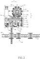
Fig. 2 is a schematic top view of the cell and medicament dispensing device inFig. 1 ; -
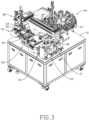
Fig. 3 is a partial perspective view of the cell and medicament dispensing device inFig. 1 ; -
Fig. 4 is an exploded view of the cell and medicament dispensing device inFig. 3 ; -
Fig. 5 is a partial perspective view of the cell and medicament dispensing device inFig. 1 , showing a transfer plate serving mechanism, a transfer plate retriever, and a transfer plate positioning mechanism of the dispensing device; -
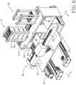
Fig. 6 is a partial perspective view of the cell and medicament dispensing device inFig. 1 , showing the transfer plate serving mechanism, the transfer plate retriever, and the transfer plate positioning mechanism from another angle; -
Fig. 7 is an exploded perspective view of the transfer plate serving mechanism, the transfer plate retriever, and the transfer plate positioning mechanism of the cell and medicament dispensing device inFig. 6 ; -
Fig. 8 andFig. 9 are operational schematic side views of the cell and medicament dispensing device inFig. 1 , showing operating statuses of the transfer plate serving mechanism viewed along a transverse direction; -
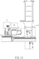
Figs. 10 to 13 are operational schematic cross sectional views of the cell and medicament dispensing device inFig. 1 , showing operating statuses of the transfer plate serving mechanism and the transfer plate positioning mechanism viewed along a longitudinal direction; -
Figs. 14 to 16 are operational schematic side views of the cell and medicament dispensing device inFig. 1 , showing operating statuses of the transfer plate positioning mechanism and an injection mechanism; -
Fig. 17 is a perspective view of a cell culture plate positioning mechanism of the cell and medicament dispensing device inFig. 1 ; -
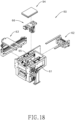
Fig. 18 is an exploded perspective view of the cell culture plate positioning mechanism of the cell and medicament dispensing device inFig. 17 ; -
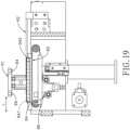
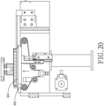
Figs. 19 and20 are operational schematic side views of the cell culture plate positioning mechanism of the cell and medicament dispensing device inFig. 17 , showing operating statuses of the cell culture plate positioning mechanism viewed along the transverse direction; -
Figs. 21 and22 are operational schematic top views of the cell culture plate positioning mechanism of the cell and medicament dispensing device inFig. 17 , showing operating statuses of the cell culture plate positioning mechanism; -
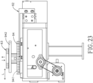
Figs. 23 and24 are operational schematic cross sectional views of the cell culture plate positioning mechanism of the cell and medicament dispensing device inFig. 17 , showing operating statuses of a lid opener of the cell culture plate positioning mechanism; -
Fig. 25 is a perspective view of a dispensing mechanism of the cell and medicament dispensing device inFig. 1 ; -
Fig. 26 is an exploded perspective view of the dispensing mechanism of the cell and medicament dispensing device inFig. 25 ; -
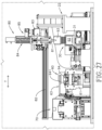
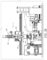
Figs. 27 to 29 are operational schematic side views of the cell and medicament dispensing device inFig. 1 , showing operating statuses of the dispensing mechanism viewed along the longitudinal direction; -
Fig. 30 is an exploded perspective view of a pipette-tip feeder of the cell and medicament dispensing device inFig. 1 ; -
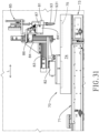
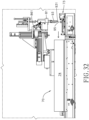
Figs. 31 and32 are operational schematic side views of the cell and medicament dispensing device inFig. 1 , showing operating statuses of the dispensing mechanism and the pipette-tip feeder along the transverse direction; -
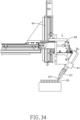
Figs. 33 to 36 are operational schematic side views of the cell and medicament dispensing device inFig. 1 , showing operating statuses for replacing pipette-tips viewed along the transverse direction; -
Fig. 37 is a schematic side view of the cell and medicament dispensing device inFig. 1 , showing a tip positioning module of the pipette-tip feeder being capable of moving upward and downward; and -
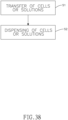
Fig. 38 is a flow chart of a cell and medicament dispensing method for drug screening in accordance with the present invention. - With reference to
Figs. 2 ,3 ,6 ,24 ,25 , and27 , a cell and medicament dispensing device for drug screening in accordance with the present invention is configured to injectmultiple solutions 91 into multiple solution recesses 921 of atransfer plate 92, and then liquid inside each of the solution recesses 921 is dispensed into multiple wells 941 (as shown inFig. 24 ) of acell culture plate 94 with apipette 93. Each of thesolutions 91 comprises one single type of medicament or one single type of cells. At least one cylindrical pipette-tip 95 (as shown inFig. 32 ) is detachably connected to a tip connector 931 (as shown inFig. 25 ) at bottom of thepipette 93. Thecell culture plate 94 preferably has anupper lid 942 detachably covering thewells 941. - With reference to
Figs. 2 to 4 , the cell and medicament dispensing device has abase 10, a transferplate serving mechanism 21, a transferplate positioning mechanism 30, aninjection mechanism 40, a cell cultureplate positioning mechanism 60, and adispensing mechanism 80. In the present embodiment, the cell and medicament dispensing device further has a cellculture plate conveyer 50, a pipette-tip feeder 70, and atransfer plate retriever 22. - The
base 10 has a transferplate entrance area 101, a receivingarea 102, and adispensing area 103 disposed thereon. The transferplate entrance area 101, the receivingarea 102, and the dispensingarea 103 are disposed apart from each other along a longitudinal direction L of thebase 10. - With reference to
Figs. 5 to 7 , the transferplate serving mechanism 21 is mounted on thebase 10 and is adjacent to the transferplate entrance area 101. Atransfer plate 92 is accommodated in the transferplate serving mechanism 21, and the transferplate serving mechanism 21 is capable of moving thetransfer plate 92 to the transferplate entrance area 101 of thebase 10. In the preferred embodiment, the transferplate serving mechanism 21 has aplate stacking bracket 211, two plate-lockingclamps 212, aplate feeder 213, and aplate lifting actuator 214. - With reference to
Figs. 8 and9 , theplate stacking bracket 211 forms a stacking space. The stacking space is configured to accommodate multiplespare transfer plates 96 that are stacked vertically. Aplate dropping opening 2111 is formed in a bottom of theplate stacking bracket 211. Thespare transfer plates 96 in the stacking space are capable of dropping down through theplate dropping opening 2111. - Each of the two plate-locking
clamps 212 is mounted on a respective side of two opposite sides of theplate dropping opening 2111. The two plate-lockingclamps 212 are capable of moving toward each other to prevent thespare transfer plates 96 from passing through theplate dropping opening 2111. - The
plate feeder 213 is mounted under theplate dropping opening 2111 and is configured to receive thetransfer plate 92 or thespare transfer plates 96 dropping down from theplate dropping opening 2111. With reference toFigs. 10 and11 , theplate feeder 213 is capable of moving to the transferplate entrance area 101 on thebase 10. With reference toFigs. 8 and9 , theplate feeder 213 has aplate lifting opening 2131 which is formed through two opposite sides of theplate feeder 213. With reference toFigs. 7 and8 , theplate lifting actuator 214 is mounted under theplate lifting opening 2131 and capable of moving upward to protrude through theplate lifting opening 2131. - The transfer
plate positioning mechanism 30 is mounted on thebase 10 and adjacent to the transferplate serving mechanism 21. The transferplate positioning mechanism 30 has apositioning slider 31, a first platelinear module 32, a second platelinear module 33, a sliding plate-cover 34, acover driving motor 35, and acover gear rack 36. - With reference to
Figs. 6 ,7 , and14 to 16 , thepositioning slider 31 is configured to connect with thetransfer plate 92. Thepositioning slider 31 is movably mounted on thebase 10 and selectively corresponds in position to the transferplate entrance area 101, the receivingarea 102, or the dispensingarea 103. - To be specific, the first plate
linear module 32 is mounted on thebase 10 and extends along a transverse direction T of thebase 10. The second platelinear module 33 is mounted on the first platelinear module 32 and extends along the longitudinal direction L of thebase 10. Thepositioning slider 31 is mounted on the second platelinear module 33 such that thepositioning slider 31 is movable in both the longitudinal direction L and transverse direction T. - In the preferred embodiment, the
plate feeder 213 of the transferplate serving mechanism 21 is movable to a position above thepositioning slider 31, and thepositioning slider 31 is capable of moving upward and downward such that thetransfer plate 92 can be transferred from theplate feeder 213 to thepositioning slider 31. Detailed operating steps of thepositioning slider 31 are as described below. - 1. With reference to
Figs. 10 to 11 , thepositioning slider 31 moves to the transferplate entrance area 101, and theplate feeder 213 moves to the position above thepositioning slider 31. - 2. With reference to
Figs. 11 and12 , thepositioning slider 31 moves upward to protrude through theplate feeder 213 via theplate lifting opening 2131 such that thetransfer plate 92 rested on theplate feeder 213 is lifted by thepositioning slider 31 and connected with thepositioning slider 31. - 3. With reference to
Figs. 12 and13 , theplate feeder 213 moves away from the position above thepositioning slider 31, and then thepositioning slider 31 moves downward to return to its original height position. - With reference to
Figs. 6 ,15 , and16 , thecover driving motor 35 is mounted on thepositioning slider 31. Thecover gear rack 36 is mounted on thepositioning slider 31, is movable along the longitudinal direction L, and is coupled to an output axis of thecover driving motor 35. The sliding plate-cover 34 is fixed to thecover gear rack 36 such that when thecover gear rack 36 moves relative to thepositioning slider 31, the sliding plate-cover 34 is driven by thecover gear rack 36 to move relative to thepositioning slider 31. As a result, the sliding plate-cover 34 is movable to a position above thepositioning slider 31 to cover thetransfer plate 92 and to prevent foreign objects from falling into the solution recesses 921. - The structure for moving the sliding plate-
cover 34 is not limited thereby, as long as the sliding plate-cover 34 is capable of selectively covering the solution recesses 921 of thetransfer plate 92. - The
injection mechanism 40 is mounted on thebase 10 and adjacent to the transferplate positioning mechanism 30. Theinjection mechanism 40 has multiple injection heads 41. Each of the injection heads 41 is in fluid communication with a respective one of thesolutions 91, and is movable to the receivingarea 102 of thebase 10. Theaforementioned positioning slider 31 is configured to align any one of the solution recesses 921 of thetransfer plate 92 to theinjection head 41 that is located in the receivingarea 102 such that saidinjection head 41 injects one of thesolutions 91 into thecorresponding solution recess 921. - In the preferred embodiment, the
injection mechanism 40 has arotary seat 42 rotatably mounted on thebase 10. The injection heads 41 are mounted on therotary seat 42 and disposed apart from each other around a rotating axis of therotary seat 42. Rotation of therotary seat 42 moves the injection heads 41 to the receivingarea 102 for a given positioning, and then theinjection head 41 in the receivingarea 102 is aligned to therespective solution recess 921 by controlling thepositioning slider 31 to the fine-tune position of thetransfer plate 92 in both the longitudinal direction L and the transverse direction T. - With reference to
Figs. 1 and2 , the cellculture plate conveyer 50 is located on a side of thebase 10 and configured to deliver the ready-to-processcell culture plate 94 from a cell culture device (not shown in figures) to thebase 10. Processedcell culture plate 94 is also returned to the cell culture device by the cellculture plate conveyer 50. - The cell
culture plate conveyer 50 has aninput conveyor belt 51, anoutput conveyor belt 52, and a cellculture plate elevator 53. Theinput conveyor belt 51 is configured to deliver the ready-to-processcell culture plate 94 to the cell cultureplate positioning mechanism 60. Theoutput conveyor belt 52 is disposed under theinput conveyor belt 51. Theinput conveyor belt 51 and theoutput conveyor belt 52 operate in reverse directions. The cellculture plate elevator 53 is mounted to an end of theinput conveyor belt 51, and is capable of moving downward to an end of theoutput conveyor belt 52 to transfer thecell culture plate 94 from theinput conveyor belt 51 to theoutput conveyor belt 52. - With reference to
Figs. 17 and18 , the cell cultureplate positioning mechanism 60 is mounted on thebase 10 and configured to connect with thecell culture plate 94. The cell cultureplate positioning mechanism 60 has apositioning seat 61 and aprimary positioning module 62; in the preferred embodiment, the cell cultureplate positioning mechanism 60 further has alid opener 63,multiple suction cups 64, a cell cultureplate transfer module 65, and asecondary positioning module 66. - The positioning
seat 61 is mounted on thebase 10 and configured to accommodate thecell culture plate 94. In the preferred embodiment, thecell culture plate 94 is automatically delivered to thepositioning seat 61 by the cellculture plate conveyer 50. Processedcell culture plates 94 are also returned to the cell culture device by the cellculture plate conveyer 50. - With reference to
Figs. 21 and22 , theprimary positioning module 62 is mounted on thepositioning seat 61 and configured to clamp the two opposite sides of thecell culture plate 94. To be precise, theprimary positioning module 62 is a 2-Jaw parallel gripper, and can be controlled to clamp thecell culture plate 94 such that a position of thecell culture plate 94 in the transverse direction T is fixed. Theprimary positioning module 62 preferably clamps the two opposite sides of thecell culture plate 94 that face toward and move longitudinally away from the transverse direction T. - With reference to
Figs. 23 and24 , thelid opener 63 is mounted above the positioningseat 61. Thelid opener 63 is capable of moving upward and downward, and is capable of moving sideways. Thelid opener 63 is movable to a position above thecell culture plate 94. The suction cups 64 are mounted on a bottom surface of thelid opener 63 and are configured to adhere to theupper lid 942 of thecell culture plate 94. In the preferred embodiment, thesuction cups 64 are connected to a vacuum generator (not shown in figures) such that thesuction cups 64 are adhered to theupper lid 942 by vacuum pressure. In another preferred embodiment, onesuction cup 64 is sufficient for adhering to theupper lid 942. - With reference to
Figs. 18 to 20 , the cell cultureplate transfer module 65 is mounted in thepositioning seat 61, and is preferably a pair of parallel conveyer belts. The cell cultureplate transfer module 65 is capable of moving thecell culture plate 94 rested on thepositioning seat 61 toward or away from the cellculture plate conveyer 50. - The
secondary positioning module 66 is mounted in thepositioning seat 61, is capable of moving upward or downward, and is configured to lift thecell culture plate 94 rested on thepositioning seat 61. When thecell culture plate 94 is lifted by thesecondary positioning module 66, two ends of thesecondary positioning module 66 attach two opposite sides of thecell culture plate 94 facing toward or moving along with the longitudinal direction L to fix a position of thecell culture plate 94 in the longitudinal direction L. - Detailed operating steps of the cell culture
plate positioning mechanism 60 are as described below. - 1. The cell
culture plate conveyer 50 delivers a ready-to-processcell culture plate 94 to thepositioning seat 61. The cell cultureplate transfer module 65 roughly adjust a position of thecell culture plate 94 on thepositioning seat 61. - 2. With reference to
Figs. 19 and20 , thesecondary positioning module 66 moves upward to lift thecell culture plate 94 and fix the position of thecell culture plate 94 in the longitudinal direction L. - 3. With reference to
Figs. 21 and22 , theprimary positioning module 62 clamps the two opposite sides of thecell culture plate 94 that face toward and move longitudinally away from the transverse direction T such that a position of thecell culture plate 94 in the transverse direction T is fixed. - 4. With reference to
Fig. 23 , thelid opener 63 moves downward to adhere to theupper lid 942 with thesuction cups 64, and then thelid opener 63 moves upwards to separate theupper lid 942 from thecell culture plate 94. - 5. With reference to
Figs. 23 and24 , thelid opener 63 moves sideways away from the position above thecell culture plate 94 to uncover partially thewells 941 of thecell culture plate 94. - With reference to
Figs. 30 to 32 , the pipette-tip feeder 70 is mounted on thebase 10 and configured to deliver pipette-tips 95 packed in boxes. The pipette-tip feeder 70 has aninput conveyer belt 71, anoutput conveyer belt 72, atip positioning module 73, a slidingtip cover 74, and at least oneUV lamp 75. - The
tip positioning module 73 is mounted on an end of theinput conveyer belt 71. Theoutput conveyer belt 72 is mounted under theinput conveyer belt 71. Theoutput conveyer belt 72 and theinput conveyer belt 71 operate in opposite directions. Thetip positioning module 73 is capable of moving downward to align with an end of theoutput conveyer belt 72. Theinput conveyer belt 71 is configured to deliver unused pipette-tips 95 packed in boxes to thetip positioning module 73, and then thetip positioning module 73 fine-tunes a position of the pipette-tip 95 for other mechanism of the present invention. - The sliding
tip cover 74 is movably mounted on theinput conveyer belt 71 and is movable to a position above thetip positioning module 73 to cover partially the pipette-tips 95 in use, thereby preventing the pipette-tips 95 unused yet from being contaminated. At least oneUV lamp 75 is mounted in an inner surface of the slidingtip cover 74 to maintain the unused pipette-tips 95 in a sterilized condition with ultraviolet irradiation. - With reference to
Figs. 25 to 27 , thedispensing mechanism 80 is mounted on thebase 10. Thedispensing mechanism 80 has a dispensingseat 81. In the preferred embodiment, thedispensing mechanism 80 further has a first dispensinglinear module 82, a second dispensinglinear module 83, a third dispensinglinear module 84, atip ejector 85, atilt actuator 86, and apivot axle 87. - The dispensing
seat 81 is configured to fix thepipette 93 and configured to control aspirate and discharge operation of thepipette 93. The dispensingseat 81 is movable relative to thebase 10 and is movable back and forth between a position above the dispensingarea 103 of thebase 10 and a position above the cell cultureplate positioning mechanism 60. When the dispensingseat 81 is above the dispensingarea 103, the dispensingseat 81 is configured to insert thepipette 93 with the at least one pipette-tip 95 into any one of the solution recesses 921 of thetransfer plate 92 and execute the aspirate operation of thepipette 93 to draw up liquid inside thesolution recess 921. When the dispensingseat 81 is above the cell cultureplate positioning mechanism 60, the dispensingseat 81 executes the discharge operation of thepipette 93 to release thesolution 91 aspired in the at least one pipette-tip 95 into one of thewells 941 of thecell culture plate 94. - In the preferred embodiment, the dispensing
seat 81 moves and inserts the pipette-tip 95 into thewells 941 via the first dispensinglinear module 82, the second dispensinglinear module 83, and the third dispensinglinear module 84. To be specific, the first dispensinglinear module 82 is mounted on thebase 10 and extends in the transverse direction T. The second dispensinglinear module 83 is mounted on the first dispensinglinear module 82 and extends in the longitudinal direction L. The third dispensinglinear module 84 is mounted on the second dispensinglinear module 83 and extends in vertical direction. The dispensingseat 81 is mounted on the third dispensinglinear module 84. As a result, the dispensingseat 81 has 3 degrees of freedom via the dispensinglinear modules - Additionally, the dispensing
seat 81 in this embodiment is movable to a position above thetip positioning module 73 of the pipette-tip feeder 70, and then the dispensingseat 81 is movable toward thetip positioning module 73 to connect with the new pipette-tips 95. Furthermore, the dispensingseat 81 is pivotally mounted on thebase 10. Rotation of the dispensingseat 81 relative to thebase 10 is capable of aligning thetip connectors 931 of thepipette 93 with pipette-tips 95 on thetip positioning module 73 such that the centerline of thetip connectors 931 are parallel to the centerline of the pipette-tips 95; the rotation of the dispensingseat 81 relative to thebase 10 is also capable of making the centerline of thetip connectors 931 inclined to the centerline of the pipette-tips 95. - With reference to
Figs. 25 ,32 , and33 , to be precise, the dispensingseat 81 is pivotally mounted on a connectingseat 841 of the third dispensinglinear module 84 via thepivot axle 87, and thepivot axle 87 is nonparallel to thetip connectors 931. To be more precise, thepivot axle 87 substantially extends in the transverse direction T, and thepivot axle 87 is substantially perpendicular to thetip connectors 931. As a result, the rotation of the dispensingseat 81 is capable of adjusting the centerline of thetip connectors 931 by the vertical line; it means that the rotation of the dispensingseat 81 is also capable of tilting thetip connectors 931 such that the centerline of thetip connectors 931 form an adjustable angle with the vertical line. - In the preferred embodiment, the
tilt actuator 86 is a linear actuator mounted on the connectingseat 841. Ashaft 861 of thetilt actuator 86 is connected to the dispensingseat 81 to control a rotating angle of the dispensingseat 81 around thepivot axle 87. - The
tip ejector 85 is mounted on the dispensingseat 81 and configured to press against thepipette 93 to remove the pipette-tip 95 from thepipette 93. With reference toFig. 26 , thetip ejector 85 has amotor 851 and arack 852, and themotor 851 drives therack 852 to press against a release button (not shown in figures) on thepipette 93 to remove the pipette-tip 95 from thepipette 93. - Coordination between the pipette-
tip feeder 70 and thedispensing mechanism 80 makes automatic replacement of the pipette-tips 95 possible, and detailed operating steps are as described below. - 1. The
tip ejector 85 presses against the release button on thepipette 93 to remove the pipette-tips 95 from thepipette 93. - 2. With reference to
Figs. 29 and31 , the dispensingseat 81 moves to the position above thetip positioning module 73. - 3. With reference to
Fig. 32 , the slidingtip cover 74 moves oppositely away from thetip positioning module 73 to reveal the pipette-tips 95 on thetip positioning module 73. - 4. With reference to
Fig. 33 , the dispensingseat 81 is tilted by thetilt actuator 86 such that the centerline of thetip connectors 931 form an angle with the vertical line. - 5. With reference to
Figs. 33 and34 , the dispensingseat 81 moves downward to partially insert a distal end 9311 (as shown inFig. 33 ) of each of thetip connectors 931 into a respective one of the pipette-tips 95. - 6. With reference to
Figs. 35 and36 , thetilt actuator 86 gradually straightens the dispensingseat 81 to align the centerline of thetip connectors 931 to match with the vertical line again. In the meantime, the dispensinglinear modules seat 81 to gradually press thetip connectors 931 against the pipette-tips 95 such that thetip connectors 931 are eventually connected with the pipette-tips 95, and then the dispensingseat 81 moves upward to continue dispensing operation. - 7. With reference to
Fig. 37 , when the pipette-tips 95 delivered in a box have been depleted, thetip positioning module 73 moves downward to align with the end of theoutput conveyer belt 72 to send away the empty box using theoutput conveyer belt 72. - The box retriever for the box of pipette-
tips 95 is substantially similar to the transferplate serving mechanism 21 aforementioned. The difference between thetransfer plate retriever 22 and the transferplate serving mechanism 21 is that thetransfer plate retriever 22 is configured to recycle usedtransfer plates 92, and therefore operating procedure of thetransfer plate retriever 22 is in a reverse order compared with the transferplate serving mechanism 21. That is, thetransfer plate retriever 22 detaches the usedtransfer plates 92 with the transferplate positioning mechanism 30, and then stacks the usedtransfer plates 92 in a bottom-up way. - With reference to
Fig. 38 , a cell and medicament dispensing method for drug screening in accordance with the present invention comprises the following steps: the first step (S1) is transfer of cells or solutions; the second step (S2) is dispensing of cells or solutions. The cell and medicament dispensing method is performed by the aforementioned cell and medicament dispensing device, but not limited thereto. - The first step (S1) is transfer of cells or solutions. With reference to
Figs. 10 to 15 , theplate feeder 213 of the transferplate serving mechanism 21 moves thetransfer plate 92 to the transferplate entrance area 101 on thebase 10. Thetransfer plate 92 has multiple solution recesses 921 as aforementioned. Thepositioning slider 31 of the transferplate positioning mechanism 30 moves to the transferplate entrance area 101 and connects with thetransfer plate 92. Thepositioning slider 31 moves thetransfer plate 92 to the receivingarea 102 of thebase 10. - With reference to
Figs. 3 ,6 , and15 , theinjection mechanism 40 injectsmultiple solutions 91 into the solution recesses 921 of thetransfer plate 92. Each of the solution recesses 921 may be injected with onesingle solution 91, or may be injected with multiple kinds of thesolutions 91. Each of thesolutions 91 comprises one single type of medicament or cells. In the preferred embodiment, the sliding plate-cover 34 partially covers the openings of the solution recesses 921 to prevent foreign objects from falling into the unused part of solution recesses 921. - With reference to
Figs. 8 and9 , multiplespare transfer plates 96 can be stacked on the transferplate serving mechanism 21. After theplate feeder 213 moves thetransfer plate 92 to the transferplate entrance area 101 of thebase 10, the transferplate serving mechanism 21 moves the bottommostspare transfer plate 96 to theplate feeder 213. By moving the bottommostspare transfer plate 96 first, risk of foreign objects falling into thespare transfer plate 96 is minimized. - In the preferred embodiment, the plate-locking
clamps 212 first move away from each other, allowing thespare transfer plate 96 to drop down. In the meantime, theplate lifting actuator 214 moves upward and protrudes through theplate lifting opening 2131 such that only the bottommostspare transfer plate 96 is located under theplate dropping opening 2111, keeping the otherspare transfer plates 96 still above theplate dropping opening 2111. Then, the plate-lockingclamps 212 move toward each other to prevent the otherspare transfer plates 96 from dropping through theplate dropping opening 2111, and then theplate lifting actuator 214 moves downward to its original position such that the bottommostspare transfer plate 96 can stay and fix on theplate feeder 213. - The second step (S2) is dispensing of cells or solutions. With reference to
Figs. 14 to 16 , thepositioning slider 31 moves thetransfer plate 92 to the dispensingarea 103 on thebase 10. Thecell culture plate 94 hasmultiple wells 941 as aforementioned. Thedispensing mechanism 80 moves thepipette 93 back and forth between the position above the dispensingarea 103 and the position above thecell culture plate 94 to dispense liquid in each of the solution recesses 921 of thetransfer plate 92 into thewells 941 of thecell culture plate 94. - In the preferred embodiment, the sliding plate-
cover 34 moves away from thetransfer plate 92 to uncover one of the openings of the solution recesses 921. After thepipette 93 dispenses liquid in said one of the openings of the solution recesses 921, the sliding plate-cover 34 moves back toward thetransfer plate 92 to cover fully the openings of the solution recesses 921 again. - In summary, by coordination among the transfer
plate serving mechanism 21, the transferplate positioning mechanism 30, and theinjection mechanism 40, liquids and cells for drug screening are automatically transferred to the solution recesses 921 of thetransfer plate 92. Afterwards, liquid in each of the solution recesses 921 is automatically dispensed into thewells 941 of thecell culture plate 94 by coordination between the transferplate positioning mechanism 30 and thedispensing mechanism 80. As a result, the process of drug screening is automated to reduce labor and improve quality significantly.
Claims (10)
- A cell and medicament dispensing device for drug screening, characterized in that the cell and medicament dispensing device is configured to inject multiple solutions (91) into multiple solution recesses (921) of a transfer plate (92); then, liquid inside each of the solution recesses (921) dispensed into multiple wells (941) of a cell culture plate (94) with a pipette (93); at least one pipette-tip (95) detachably connected to a bottom of the pipette (93); the cell and medicament dispensing device comprising:a base (10) having a transfer plate entrance area (101), a receiving area (102), and a dispensing area (103) thereon;a transfer plate serving mechanism (21) mounted on the base (10) and being adjacent to the transfer plate entrance area (101); the transfer plate serving mechanism (21) configured to accommodate the transfer plate (92) and being capable of moving the transfer plate (92) to the transfer plate entrance area (101) of the base (10), the transfer plate serving mechanism (21) havinga plate stacking bracket (211) forming a stacking space; the stacking space configured to accommodate multiple spare transfer plates (96) that are stacked vertically;a plate dropping opening (2111) formed in a bottom of the plate stacking bracket (211); the spare transfer plates (96) being capable of dropping through the plate dropping opening (2111);two plate-locking clamps (212); each of the plate-locking clamps (212) mounted on a respective side of two opposite sides of the plate dropping opening (2111); the two plate-locking clamps (212) being capable of moving toward each other to prevent the spare transfer plates (96) from passing through the plate dropping opening (2111);a plate feeder (213) mounted under the plate dropping opening (2111) and configured to receive the transfer plates (92) dropped through the plate dropping opening (2111); the plate feeder (213) being movable to the transfer plate entrance area (101) of the base (10); the plate feeder (213) having:
a plate lifting opening (2131) formed through two opposite sides of the plate feeder (213); anda plate lifting actuator (214) mounted under the plate lifting opening (2131) and being capable of moving upward to protrude through the plate lifting opening (2131);a transfer plate positioning mechanism (30) mounted on the base (10) and being adjacent to the transfer plate serving mechanism (21); the transfer plate positioning mechanism (30) having:
a positioning slider (31) configured to connect with the transfer plate (92); the positioning slider (31) movably mounted on the base (10) and selectively corresponding in position to the transfer plate entrance area (101), the receiving area (102), or the dispensing area (103), wherein the plate feeder (213) is configured to move to a position above the positioning slider (31) to transfer the transfer plate (92) to the positioning slider (31);an injection mechanism (40) mounted on the base (10) and being adjacent to the transfer plate positioning mechanism (30); the injection mechanism (40) having:
multiple injection heads (41); each of the injection heads (41) being in fluid communication with a respective one of the solutions (91) and being movable to the receiving area (102) of the base (10); wherein the positioning slider (31) is configured to align any one of the solution recesses (921) of the transfer plate (92) to the injection head (41) located in the receiving area (102) such that said injection head (41) injects one of the solutions (91) into a corresponding one of the solution recesses(921);a cell culture plate positioning mechanism (60) mounted on the base (10) and configured to connect with the cell culture plate (94); the cell culture plate positioning mechanism (60) having:a positioning seat (61) mounted on the base (10) and configured to accommodate the cell culture plate (94); anda primary positioning module (62) mounted on the positioning seat (61) and configured to clamp the cell culture plate (94); anda dispensing mechanism (80) mounted on the base (10) and having:
a dispensing seat (81) configured to fix the pipette (93) and configured to control aspirate and discharge operation of the pipette (93); the dispensing seat (81) being movable relative to the base (10) and being movable back and forth between a position above the dispensing area (103) of the base (10) and a position above the cell culture plate positioning mechanism (60);wherein the dispensing seat (81) is configured to move to a position above the dispensing area (103) to insert the at least one pipette-tip (95) of the pipette (93) into any one of the solution recesses (921) of the transfer plate (92) and execute the aspirate operation of the pipette (93); andwherein the dispensing seat (81) is configured to move to a position above the cell culture plate positioning mechanism (60)and execute the discharge operation of the pipette (93) to release the solution (91) aspired in the at least one pipette-tip (95) into one of the wells (941) of the cell culture plate (94). - The cell and medicament dispensing device as claimed in claim 1 further comprising:a pipette-tip feeder (70) mounted on the base (10) and havingan input conveyer belt (71); anda tip positioning module (73) mounted on an end of the input conveyer belt (71);the dispensing seat (81) of the dispensing mechanism (80) being movable to a position above the tip positioning module (73) of the pipette-tip feeder (70) and moveable toward the tip positioning module (73).
- The cell and medicament dispensing device as claimed in claim 2, whereinthe dispensing seat (81) of the dispensing mechanism (80) is pivotal around a pivot axle (87); the pivot axle (87) is nonparallel to the vertical line;the dispensing mechanism (80) further has
a tilt actuator (86) connected to the dispensing seat (81) and controlling a rotating angle of the dispensing seat (81) around the pivot axle (87). - The cell and medicament dispensing device as claimed in claim 2, whereinthe pipette-tip feeder (70) further has:
an output conveyer belt (72) mounted under the input conveyer belt (71); the output conveyer belt (72) and the input conveyer belt (71) operating in opposite directions;the tip positioning module (73) is capable of moving downward to align with an end of the output conveyer belt (72). - The cell and medicament dispensing device as claimed in any one of claims 1 to 4, whereinthe cell culture plate (94) has an upper lid (942) detachably covering the wells (941); andthe cell culture plate positioning mechanism (60) further hasa lid opener (63) mounted above the positioning seat (61); the lid opener (63) being capable of moving upward and downward, and capable of moving sideways; the lid opener (63) being movable to a position above the cell culture plate (94); andat least one suction cup (64) mounted on a bottom surface of the lid opener (63) and configured to adhere to the upper lid (942) of the cell culture plate (94).
- The cell and medicament dispensing device as claimed in any one of claims 1 to 4, whereinthe positioning slider (31) of the transfer plate positioning mechanism (30) is capable of moving upward and downward; andwhen the positioning slider (31) corresponds in position to the transfer plate entrance area (101), the plate feeder (213) of the transfer plate serving mechanism (21) is movable to a position above the positioning slider (31), and the positioning slider (31) is capable of moving upward to protrude through the plate lifting opening (2131).
- The cell and medicament dispensing device as claimed in any one of claims 1 to 4, wherein the transfer plate positioning mechanism (30) has
a sliding plate-cover (34) movably mounted on the positioning slider (31) and being movable to a position above the positioning slider (31) to cover openings of the solution recesses (921) of the transfer plate (92). - A cell and medicament dispensing method for drug screening, characterized in that the cell and medicament dispensing method comprises steps as follows:(a) transfer of cells or solutions (91), wherein a transfer plate serving mechanism (21) has a plate stacking bracket (211), a plate dropping opening (2111), two plate-locking clamps (212), a plate feeder (213), and a plate lifting actuator (214); the plate stacking bracket (211) forms a stacking space; the stacking space is configured to accommodate multiple spare transfer plates (96) that are stacked vertically; the plate dropping opening (2111) is formed in a bottom of the plate stacking bracket (211); the spare transfer plates (96) are capable of dropping through the plate dropping opening (2111); the two plate-locking clamps (212) are each mounted on a respective side of two opposite sides of the plate dropping opening (2111); the two plate-locking clamps (212) are capable of moving toward each other to prevent the spare transfer plates (96) from passing through the plate dropping opening (2111); the plate feeder (213) is mounted under the plate dropping opening (2111) and is configured to receive a transfer plate (92) dropped through the plate dropping opening (2111); the plate feeder (213) is movable to the transfer plate entrance area (101) of the base (10) and has a plate lifting opening (2131) formed through two opposite sides of the plate feeder (213); the plate lifting actuator (214) is mounted under the plate lifting opening (2131) and is capable of moving upward to protrude through the plate lifting opening (2131); the plate feeder (213) of the transfer plate serving mechanism (21) moves the transfer plate (92) to a transfer plate entrance area (101) on a base (10); the transfer plate (92) has multiple solution recesses (921) formed thereon; a positioning slider (31) of a transfer plate positioning mechanism (30) moves to the transfer plate entrance area (101) and connects with the transfer plate (92) located in the transfer plate entrance area (101); the plate feeder (213) of the transfer plate serving mechanism (21) moves to the position above the positioning slider (31) to transfer the transfer plate (92) to the positioning slider (31); the positioning slider (31) moves the transfer plate (92) to a receiving area (102) on the base (10); an injection mechanism (40) injects multiple solutions (91) into the solution recesses (921) of the transfer plate (92); and(b) dispensing of cells or solutions (91), wherein the positioning slider (31) moves the transfer plate (92) to a dispensing area (103) on the base (10); a cell culture plate (94) has multiple wells (941); a dispensing mechanism (80) moves a pipette (93) back and forth between a position above the dispensing area (103) on the base (10) and a position above the cell culture plate (94) on the positioning slider (31) to dispense liquid in each of the solution recesses (921) into the wells (941) of the cell culture plate (94).
- The cell and medicament dispensing method as claimed in claim 8, wherein in the step (a), after the plate feeder (213) moves the transfer plate (92) to the transfer plate entrance area (101) on the base (10), the transfer plate serving mechanism (21) moves the bottommost spare transfer plate (96) to the plate feeder (213).
- The cell and medicament dispensing method as claimed in claim 8 or 9, whereinin the step (a), after the injection mechanism (40) injects solutions (91) into the solution recesses (921) of the transfer plate (92), a sliding plate-cover (34) covers openings of the solution recesses (921) of the transfer plate (92); andin the step (b), the sliding plate-cover (34) moves away from the transfer plate (92) to uncover one of the solution recesses (921) before the pipette (93) dispenses liquid in said one of the solution recesses (921); after the pipette (93) dispenses liquid in said one of the solution recesses (921), the sliding plate-cover (34) moves back toward the transfer plate to cover fully the openings of the solution recesses (921).
Priority Applications (1)
| Application Number | Priority Date | Filing Date | Title |
|---|---|---|---|
| EP21205920.8A EP4074814B1 (en) | 2021-11-02 | 2021-11-02 | Cell and medicament dispensing device for drug screening and method thereof |
Applications Claiming Priority (1)
| Application Number | Priority Date | Filing Date | Title |
|---|---|---|---|
| EP21205920.8A EP4074814B1 (en) | 2021-11-02 | 2021-11-02 | Cell and medicament dispensing device for drug screening and method thereof |
Publications (4)
| Publication Number | Publication Date |
|---|---|
| EP4074814A1 EP4074814A1 (en) | 2022-10-19 |
| EP4074814A8 EP4074814A8 (en) | 2022-11-23 |
| EP4074814B1 true EP4074814B1 (en) | 2025-01-15 |
| EP4074814C0 EP4074814C0 (en) | 2025-01-15 |
Family
ID=78500473
Family Applications (1)
| Application Number | Title | Priority Date | Filing Date |
|---|---|---|---|
| EP21205920.8A Active EP4074814B1 (en) | 2021-11-02 | 2021-11-02 | Cell and medicament dispensing device for drug screening and method thereof |
Country Status (1)
| Country | Link |
|---|---|
| EP (1) | EP4074814B1 (en) |
Family Cites Families (4)
| Publication number | Priority date | Publication date | Assignee | Title |
|---|---|---|---|---|
| US5985214A (en) * | 1997-05-16 | 1999-11-16 | Aurora Biosciences Corporation | Systems and methods for rapidly identifying useful chemicals in liquid samples |
| US6982063B2 (en) * | 2001-05-25 | 2006-01-03 | Matrix Technologies Corp | Automated pipetting system |
| US7695688B2 (en) * | 2003-09-19 | 2010-04-13 | Applied Biosystems, Llc | High density plate filler |
| JP7033449B2 (en) * | 2017-12-26 | 2022-03-10 | 川崎重工業株式会社 | Dispensing robot, control method and dispensing method of dispensing robot |
-
2021
- 2021-11-02 EP EP21205920.8A patent/EP4074814B1/en active Active
Also Published As
| Publication number | Publication date |
|---|---|
| EP4074814A8 (en) | 2022-11-23 |
| EP4074814A1 (en) | 2022-10-19 |
| EP4074814C0 (en) | 2025-01-15 |
Similar Documents
| Publication | Publication Date | Title |
|---|---|---|
| EP1363736B1 (en) | Extruding gel material for gel electrophoresis | |
| US11624048B2 (en) | Switching valve and suction-discharge device including the same | |
| US6998094B2 (en) | Apparatus for and methods of handling biological sample containers | |
| US6669432B2 (en) | Apparatus and method for handling pipetting tip magazines | |
| US6982063B2 (en) | Automated pipetting system | |
| US6843962B2 (en) | Apparatus for and methods of handling biological sample containers | |
| CN113816061A (en) | Automatic medicine cutting and dispensing system for small traditional Chinese medicine packages, medicine feeding control method and medicine dispensing control method | |
| US11761974B2 (en) | Cell and medicament dispensing device for drug screening and method thereof | |
| CN112457972A (en) | Pretreatment device and method for PCR detection of virus | |
| JP4135567B2 (en) | Cap removal device | |
| EP4074814A1 (en) | Cell and medicament dispensing device for drug screening and method thereof | |
| CN112782415A (en) | Test pretreatment device, medical equipment and detection method | |
| JP7208336B1 (en) | CULTURED CELLS FOR SCREENING, MEDICINE DISPENSING APPARATUS, AND DISPENSING METHOD THEREOF | |
| WO2023275894A1 (en) | Automated coverslipper for large format slides with switchable compatibility to handle multi format slides | |
| CN104816860B (en) | Apparatus and method for preparing a container for removal from a tray enclosed by a tray | |
| CN115970783B (en) | Cell and drug dispensing device and method for drug screening | |
| TWI773520B (en) | Cell and drug dispensing device and method for drug screening | |
| CN112693877B (en) | Feeding device, medical equipment and feeding method | |
| CN114261936A (en) | Filling equipment and filling method thereof | |
| CN119490907B (en) | Liquid preparation system | |
| JP7496009B1 (en) | Gravity-type dispensing device, cell subculture device equipped with the same, and cell subculture method using the cell subculture device | |
| CN115007243B (en) | A fully automatic liquid transfer workstation | |
| KR102337372B1 (en) | Apparatus for manufacturing artificail skin and micro plate | |
| CN117741168A (en) | Full-automatic multi-station centrifugal liquid-based pelleter | |
| CN120246352A (en) | A fully automatic straw packaging equipment |
Legal Events
| Date | Code | Title | Description |
|---|---|---|---|
| PUAI | Public reference made under article 153(3) epc to a published international application that has entered the european phase |
Free format text: ORIGINAL CODE: 0009012 |
|
| STAA | Information on the status of an ep patent application or granted ep patent |
Free format text: STATUS: THE APPLICATION HAS BEEN PUBLISHED |
|
| STAA | Information on the status of an ep patent application or granted ep patent |
Free format text: STATUS: REQUEST FOR EXAMINATION WAS MADE |
|
| AK | Designated contracting states |
Kind code of ref document: A1 Designated state(s): AL AT BE BG CH CY CZ DE DK EE ES FI FR GB GR HR HU IE IS IT LI LT LU LV MC MK MT NL NO PL PT RO RS SE SI SK SM TR |
|
| 17P | Request for examination filed |
Effective date: 20220928 |
|
| RBV | Designated contracting states (corrected) |
Designated state(s): AL AT BE BG CH CY CZ DE DK EE ES FI FR GB GR HR HU IE IS IT LI LT LU LV MC MK MT NL NO PL PT RO RS SE SI SK SM TR |
|
| GRAP | Despatch of communication of intention to grant a patent |
Free format text: ORIGINAL CODE: EPIDOSNIGR1 |
|
| STAA | Information on the status of an ep patent application or granted ep patent |
Free format text: STATUS: GRANT OF PATENT IS INTENDED |
|
| INTG | Intention to grant announced |
Effective date: 20240812 |
|
| GRAS | Grant fee paid |
Free format text: ORIGINAL CODE: EPIDOSNIGR3 |
|
| GRAA | (expected) grant |
Free format text: ORIGINAL CODE: 0009210 |
|
| STAA | Information on the status of an ep patent application or granted ep patent |
Free format text: STATUS: THE PATENT HAS BEEN GRANTED |
|
| AK | Designated contracting states |
Kind code of ref document: B1 Designated state(s): AL AT BE BG CH CY CZ DE DK EE ES FI FR GB GR HR HU IE IS IT LI LT LU LV MC MK MT NL NO PL PT RO RS SE SI SK SM TR |
|
| REG | Reference to a national code |
Ref country code: CH Ref legal event code: EP Ref country code: GB Ref legal event code: FG4D |
|
| REG | Reference to a national code |
Ref country code: DE Ref legal event code: R096 Ref document number: 602021024915 Country of ref document: DE |
|
| REG | Reference to a national code |
Ref country code: IE Ref legal event code: FG4D |
|
| U01 | Request for unitary effect filed |
Effective date: 20250210 |
|
| U07 | Unitary effect registered |
Designated state(s): AT BE BG DE DK EE FI FR IT LT LU LV MT NL PT RO SE SI Effective date: 20250214 |
|
| PG25 | Lapsed in a contracting state [announced via postgrant information from national office to epo] |
Ref country code: RS Free format text: LAPSE BECAUSE OF FAILURE TO SUBMIT A TRANSLATION OF THE DESCRIPTION OR TO PAY THE FEE WITHIN THE PRESCRIBED TIME-LIMIT Effective date: 20250415 |
|
| PG25 | Lapsed in a contracting state [announced via postgrant information from national office to epo] |
Ref country code: PL Free format text: LAPSE BECAUSE OF FAILURE TO SUBMIT A TRANSLATION OF THE DESCRIPTION OR TO PAY THE FEE WITHIN THE PRESCRIBED TIME-LIMIT Effective date: 20250115 |
|
| PG25 | Lapsed in a contracting state [announced via postgrant information from national office to epo] |
Ref country code: ES Free format text: LAPSE BECAUSE OF FAILURE TO SUBMIT A TRANSLATION OF THE DESCRIPTION OR TO PAY THE FEE WITHIN THE PRESCRIBED TIME-LIMIT Effective date: 20250115 |
|
| PG25 | Lapsed in a contracting state [announced via postgrant information from national office to epo] |
Ref country code: IS Free format text: LAPSE BECAUSE OF FAILURE TO SUBMIT A TRANSLATION OF THE DESCRIPTION OR TO PAY THE FEE WITHIN THE PRESCRIBED TIME-LIMIT Effective date: 20250515 Ref country code: NO Free format text: LAPSE BECAUSE OF FAILURE TO SUBMIT A TRANSLATION OF THE DESCRIPTION OR TO PAY THE FEE WITHIN THE PRESCRIBED TIME-LIMIT Effective date: 20250415 |
|
| PG25 | Lapsed in a contracting state [announced via postgrant information from national office to epo] |
Ref country code: HR Free format text: LAPSE BECAUSE OF FAILURE TO SUBMIT A TRANSLATION OF THE DESCRIPTION OR TO PAY THE FEE WITHIN THE PRESCRIBED TIME-LIMIT Effective date: 20250115 |
|
| PG25 | Lapsed in a contracting state [announced via postgrant information from national office to epo] |
Ref country code: GR Free format text: LAPSE BECAUSE OF FAILURE TO SUBMIT A TRANSLATION OF THE DESCRIPTION OR TO PAY THE FEE WITHIN THE PRESCRIBED TIME-LIMIT Effective date: 20250416 |
|
| PG25 | Lapsed in a contracting state [announced via postgrant information from national office to epo] |
Ref country code: SM Free format text: LAPSE BECAUSE OF FAILURE TO SUBMIT A TRANSLATION OF THE DESCRIPTION OR TO PAY THE FEE WITHIN THE PRESCRIBED TIME-LIMIT Effective date: 20250115 |
|
| PG25 | Lapsed in a contracting state [announced via postgrant information from national office to epo] |
Ref country code: CZ Free format text: LAPSE BECAUSE OF FAILURE TO SUBMIT A TRANSLATION OF THE DESCRIPTION OR TO PAY THE FEE WITHIN THE PRESCRIBED TIME-LIMIT Effective date: 20250115 |
|
| PG25 | Lapsed in a contracting state [announced via postgrant information from national office to epo] |
Ref country code: SK Free format text: LAPSE BECAUSE OF FAILURE TO SUBMIT A TRANSLATION OF THE DESCRIPTION OR TO PAY THE FEE WITHIN THE PRESCRIBED TIME-LIMIT Effective date: 20250115 |
|
| PLBE | No opposition filed within time limit |
Free format text: ORIGINAL CODE: 0009261 |
|
| STAA | Information on the status of an ep patent application or granted ep patent |
Free format text: STATUS: NO OPPOSITION FILED WITHIN TIME LIMIT |
|
| REG | Reference to a national code |
Ref country code: CH Ref legal event code: L10 Free format text: ST27 STATUS EVENT CODE: U-0-0-L10-L00 (AS PROVIDED BY THE NATIONAL OFFICE) Effective date: 20251126 |
|
| REG | Reference to a national code |
Ref country code: CH Ref legal event code: U11 Free format text: ST27 STATUS EVENT CODE: U-0-0-U10-U11 (AS PROVIDED BY THE NATIONAL OFFICE) Effective date: 20251201 |
|
| U20 | Renewal fee for the european patent with unitary effect paid |
Year of fee payment: 5 Effective date: 20251031 |
|
| 26N | No opposition filed |
Effective date: 20251016 |
|
| PGFP | Annual fee paid to national office [announced via postgrant information from national office to epo] |
Ref country code: GB Payment date: 20251015 Year of fee payment: 5 |
|
| PGFP | Annual fee paid to national office [announced via postgrant information from national office to epo] |
Ref country code: CH Payment date: 20251201 Year of fee payment: 5 |