EP4074537A1 - Optical fiber-based sensing membrane - Google Patents
Optical fiber-based sensing membrane Download PDFInfo
- Publication number
- EP4074537A1 EP4074537A1 EP22167563.0A EP22167563A EP4074537A1 EP 4074537 A1 EP4074537 A1 EP 4074537A1 EP 22167563 A EP22167563 A EP 22167563A EP 4074537 A1 EP4074537 A1 EP 4074537A1
- Authority
- EP
- European Patent Office
- Prior art keywords
- optical fiber
- sensing membrane
- based sensing
- substrate
- thermal
- Prior art date
- Legal status (The legal status is an assumption and is not a legal conclusion. Google has not performed a legal analysis and makes no representation as to the accuracy of the status listed.)
- Granted
Links
Images






Classifications
-
- G—PHYSICS
- G01—MEASURING; TESTING
- G01D—MEASURING NOT SPECIALLY ADAPTED FOR A SPECIFIC VARIABLE; ARRANGEMENTS FOR MEASURING TWO OR MORE VARIABLES NOT COVERED IN A SINGLE OTHER SUBCLASS; TARIFF METERING APPARATUS; MEASURING OR TESTING NOT OTHERWISE PROVIDED FOR
- G01D5/00—Mechanical means for transferring the output of a sensing member; Means for converting the output of a sensing member to another variable where the form or nature of the sensing member does not constrain the means for converting; Transducers not specially adapted for a specific variable
- G01D5/26—Mechanical means for transferring the output of a sensing member; Means for converting the output of a sensing member to another variable where the form or nature of the sensing member does not constrain the means for converting; Transducers not specially adapted for a specific variable characterised by optical transfer means, i.e. using infrared, visible, or ultraviolet light
- G01D5/32—Mechanical means for transferring the output of a sensing member; Means for converting the output of a sensing member to another variable where the form or nature of the sensing member does not constrain the means for converting; Transducers not specially adapted for a specific variable characterised by optical transfer means, i.e. using infrared, visible, or ultraviolet light with attenuation or whole or partial obturation of beams of light
- G01D5/34—Mechanical means for transferring the output of a sensing member; Means for converting the output of a sensing member to another variable where the form or nature of the sensing member does not constrain the means for converting; Transducers not specially adapted for a specific variable characterised by optical transfer means, i.e. using infrared, visible, or ultraviolet light with attenuation or whole or partial obturation of beams of light the beams of light being detected by photocells
- G01D5/353—Mechanical means for transferring the output of a sensing member; Means for converting the output of a sensing member to another variable where the form or nature of the sensing member does not constrain the means for converting; Transducers not specially adapted for a specific variable characterised by optical transfer means, i.e. using infrared, visible, or ultraviolet light with attenuation or whole or partial obturation of beams of light the beams of light being detected by photocells influencing the transmission properties of an optical fibre
- G01D5/3537—Optical fibre sensor using a particular arrangement of the optical fibre itself
- G01D5/35374—Particular layout of the fiber
-
- B—PERFORMING OPERATIONS; TRANSPORTING
- B60—VEHICLES IN GENERAL
- B60L—PROPULSION OF ELECTRICALLY-PROPELLED VEHICLES; SUPPLYING ELECTRIC POWER FOR AUXILIARY EQUIPMENT OF ELECTRICALLY-PROPELLED VEHICLES; ELECTRODYNAMIC BRAKE SYSTEMS FOR VEHICLES IN GENERAL; MAGNETIC SUSPENSION OR LEVITATION FOR VEHICLES; MONITORING OPERATING VARIABLES OF ELECTRICALLY-PROPELLED VEHICLES; ELECTRIC SAFETY DEVICES FOR ELECTRICALLY-PROPELLED VEHICLES
- B60L50/00—Electric propulsion with power supplied within the vehicle
- B60L50/50—Electric propulsion with power supplied within the vehicle using propulsion power supplied by batteries or fuel cells
- B60L50/60—Electric propulsion with power supplied within the vehicle using propulsion power supplied by batteries or fuel cells using power supplied by batteries
- B60L50/64—Constructional details of batteries specially adapted for electric vehicles
-
- B—PERFORMING OPERATIONS; TRANSPORTING
- B60—VEHICLES IN GENERAL
- B60L—PROPULSION OF ELECTRICALLY-PROPELLED VEHICLES; SUPPLYING ELECTRIC POWER FOR AUXILIARY EQUIPMENT OF ELECTRICALLY-PROPELLED VEHICLES; ELECTRODYNAMIC BRAKE SYSTEMS FOR VEHICLES IN GENERAL; MAGNETIC SUSPENSION OR LEVITATION FOR VEHICLES; MONITORING OPERATING VARIABLES OF ELECTRICALLY-PROPELLED VEHICLES; ELECTRIC SAFETY DEVICES FOR ELECTRICALLY-PROPELLED VEHICLES
- B60L50/00—Electric propulsion with power supplied within the vehicle
- B60L50/50—Electric propulsion with power supplied within the vehicle using propulsion power supplied by batteries or fuel cells
- B60L50/60—Electric propulsion with power supplied within the vehicle using propulsion power supplied by batteries or fuel cells using power supplied by batteries
- B60L50/66—Arrangements of batteries
-
- B—PERFORMING OPERATIONS; TRANSPORTING
- B60—VEHICLES IN GENERAL
- B60L—PROPULSION OF ELECTRICALLY-PROPELLED VEHICLES; SUPPLYING ELECTRIC POWER FOR AUXILIARY EQUIPMENT OF ELECTRICALLY-PROPELLED VEHICLES; ELECTRODYNAMIC BRAKE SYSTEMS FOR VEHICLES IN GENERAL; MAGNETIC SUSPENSION OR LEVITATION FOR VEHICLES; MONITORING OPERATING VARIABLES OF ELECTRICALLY-PROPELLED VEHICLES; ELECTRIC SAFETY DEVICES FOR ELECTRICALLY-PROPELLED VEHICLES
- B60L58/00—Methods or circuit arrangements for monitoring or controlling batteries or fuel cells, specially adapted for electric vehicles
- B60L58/10—Methods or circuit arrangements for monitoring or controlling batteries or fuel cells, specially adapted for electric vehicles for monitoring or controlling batteries
- B60L58/18—Methods or circuit arrangements for monitoring or controlling batteries or fuel cells, specially adapted for electric vehicles for monitoring or controlling batteries of two or more battery modules
-
- G—PHYSICS
- G01—MEASURING; TESTING
- G01B—MEASURING LENGTH, THICKNESS OR SIMILAR LINEAR DIMENSIONS; MEASURING ANGLES; MEASURING AREAS; MEASURING IRREGULARITIES OF SURFACES OR CONTOURS
- G01B11/00—Measuring arrangements characterised by the use of optical techniques
- G01B11/16—Measuring arrangements characterised by the use of optical techniques for measuring the deformation in a solid, e.g. optical strain gauge
- G01B11/18—Measuring arrangements characterised by the use of optical techniques for measuring the deformation in a solid, e.g. optical strain gauge using photoelastic elements
-
- G—PHYSICS
- G01—MEASURING; TESTING
- G01D—MEASURING NOT SPECIALLY ADAPTED FOR A SPECIFIC VARIABLE; ARRANGEMENTS FOR MEASURING TWO OR MORE VARIABLES NOT COVERED IN A SINGLE OTHER SUBCLASS; TARIFF METERING APPARATUS; MEASURING OR TESTING NOT OTHERWISE PROVIDED FOR
- G01D21/00—Measuring or testing not otherwise provided for
- G01D21/02—Measuring two or more variables by means not covered by a single other subclass
-
- G—PHYSICS
- G01—MEASURING; TESTING
- G01D—MEASURING NOT SPECIALLY ADAPTED FOR A SPECIFIC VARIABLE; ARRANGEMENTS FOR MEASURING TWO OR MORE VARIABLES NOT COVERED IN A SINGLE OTHER SUBCLASS; TARIFF METERING APPARATUS; MEASURING OR TESTING NOT OTHERWISE PROVIDED FOR
- G01D5/00—Mechanical means for transferring the output of a sensing member; Means for converting the output of a sensing member to another variable where the form or nature of the sensing member does not constrain the means for converting; Transducers not specially adapted for a specific variable
- G01D5/26—Mechanical means for transferring the output of a sensing member; Means for converting the output of a sensing member to another variable where the form or nature of the sensing member does not constrain the means for converting; Transducers not specially adapted for a specific variable characterised by optical transfer means, i.e. using infrared, visible, or ultraviolet light
- G01D5/32—Mechanical means for transferring the output of a sensing member; Means for converting the output of a sensing member to another variable where the form or nature of the sensing member does not constrain the means for converting; Transducers not specially adapted for a specific variable characterised by optical transfer means, i.e. using infrared, visible, or ultraviolet light with attenuation or whole or partial obturation of beams of light
- G01D5/34—Mechanical means for transferring the output of a sensing member; Means for converting the output of a sensing member to another variable where the form or nature of the sensing member does not constrain the means for converting; Transducers not specially adapted for a specific variable characterised by optical transfer means, i.e. using infrared, visible, or ultraviolet light with attenuation or whole or partial obturation of beams of light the beams of light being detected by photocells
- G01D5/353—Mechanical means for transferring the output of a sensing member; Means for converting the output of a sensing member to another variable where the form or nature of the sensing member does not constrain the means for converting; Transducers not specially adapted for a specific variable characterised by optical transfer means, i.e. using infrared, visible, or ultraviolet light with attenuation or whole or partial obturation of beams of light the beams of light being detected by photocells influencing the transmission properties of an optical fibre
- G01D5/35338—Mechanical means for transferring the output of a sensing member; Means for converting the output of a sensing member to another variable where the form or nature of the sensing member does not constrain the means for converting; Transducers not specially adapted for a specific variable characterised by optical transfer means, i.e. using infrared, visible, or ultraviolet light with attenuation or whole or partial obturation of beams of light the beams of light being detected by photocells influencing the transmission properties of an optical fibre using other arrangements than interferometer arrangements
- G01D5/35354—Sensor working in reflection
- G01D5/35358—Sensor working in reflection using backscattering to detect the measured quantity
- G01D5/35361—Sensor working in reflection using backscattering to detect the measured quantity using elastic backscattering to detect the measured quantity, e.g. using Rayleigh backscattering
-
- G—PHYSICS
- G01—MEASURING; TESTING
- G01D—MEASURING NOT SPECIALLY ADAPTED FOR A SPECIFIC VARIABLE; ARRANGEMENTS FOR MEASURING TWO OR MORE VARIABLES NOT COVERED IN A SINGLE OTHER SUBCLASS; TARIFF METERING APPARATUS; MEASURING OR TESTING NOT OTHERWISE PROVIDED FOR
- G01D5/00—Mechanical means for transferring the output of a sensing member; Means for converting the output of a sensing member to another variable where the form or nature of the sensing member does not constrain the means for converting; Transducers not specially adapted for a specific variable
- G01D5/26—Mechanical means for transferring the output of a sensing member; Means for converting the output of a sensing member to another variable where the form or nature of the sensing member does not constrain the means for converting; Transducers not specially adapted for a specific variable characterised by optical transfer means, i.e. using infrared, visible, or ultraviolet light
- G01D5/32—Mechanical means for transferring the output of a sensing member; Means for converting the output of a sensing member to another variable where the form or nature of the sensing member does not constrain the means for converting; Transducers not specially adapted for a specific variable characterised by optical transfer means, i.e. using infrared, visible, or ultraviolet light with attenuation or whole or partial obturation of beams of light
- G01D5/34—Mechanical means for transferring the output of a sensing member; Means for converting the output of a sensing member to another variable where the form or nature of the sensing member does not constrain the means for converting; Transducers not specially adapted for a specific variable characterised by optical transfer means, i.e. using infrared, visible, or ultraviolet light with attenuation or whole or partial obturation of beams of light the beams of light being detected by photocells
- G01D5/353—Mechanical means for transferring the output of a sensing member; Means for converting the output of a sensing member to another variable where the form or nature of the sensing member does not constrain the means for converting; Transducers not specially adapted for a specific variable characterised by optical transfer means, i.e. using infrared, visible, or ultraviolet light with attenuation or whole or partial obturation of beams of light the beams of light being detected by photocells influencing the transmission properties of an optical fibre
- G01D5/35338—Mechanical means for transferring the output of a sensing member; Means for converting the output of a sensing member to another variable where the form or nature of the sensing member does not constrain the means for converting; Transducers not specially adapted for a specific variable characterised by optical transfer means, i.e. using infrared, visible, or ultraviolet light with attenuation or whole or partial obturation of beams of light the beams of light being detected by photocells influencing the transmission properties of an optical fibre using other arrangements than interferometer arrangements
- G01D5/35354—Sensor working in reflection
- G01D5/35358—Sensor working in reflection using backscattering to detect the measured quantity
- G01D5/35364—Sensor working in reflection using backscattering to detect the measured quantity using inelastic backscattering to detect the measured quantity, e.g. using Brillouin or Raman backscattering
-
- G—PHYSICS
- G01—MEASURING; TESTING
- G01D—MEASURING NOT SPECIALLY ADAPTED FOR A SPECIFIC VARIABLE; ARRANGEMENTS FOR MEASURING TWO OR MORE VARIABLES NOT COVERED IN A SINGLE OTHER SUBCLASS; TARIFF METERING APPARATUS; MEASURING OR TESTING NOT OTHERWISE PROVIDED FOR
- G01D5/00—Mechanical means for transferring the output of a sensing member; Means for converting the output of a sensing member to another variable where the form or nature of the sensing member does not constrain the means for converting; Transducers not specially adapted for a specific variable
- G01D5/26—Mechanical means for transferring the output of a sensing member; Means for converting the output of a sensing member to another variable where the form or nature of the sensing member does not constrain the means for converting; Transducers not specially adapted for a specific variable characterised by optical transfer means, i.e. using infrared, visible, or ultraviolet light
- G01D5/32—Mechanical means for transferring the output of a sensing member; Means for converting the output of a sensing member to another variable where the form or nature of the sensing member does not constrain the means for converting; Transducers not specially adapted for a specific variable characterised by optical transfer means, i.e. using infrared, visible, or ultraviolet light with attenuation or whole or partial obturation of beams of light
- G01D5/34—Mechanical means for transferring the output of a sensing member; Means for converting the output of a sensing member to another variable where the form or nature of the sensing member does not constrain the means for converting; Transducers not specially adapted for a specific variable characterised by optical transfer means, i.e. using infrared, visible, or ultraviolet light with attenuation or whole or partial obturation of beams of light the beams of light being detected by photocells
- G01D5/353—Mechanical means for transferring the output of a sensing member; Means for converting the output of a sensing member to another variable where the form or nature of the sensing member does not constrain the means for converting; Transducers not specially adapted for a specific variable characterised by optical transfer means, i.e. using infrared, visible, or ultraviolet light with attenuation or whole or partial obturation of beams of light the beams of light being detected by photocells influencing the transmission properties of an optical fibre
- G01D5/3537—Optical fibre sensor using a particular arrangement of the optical fibre itself
- G01D5/35377—Means for amplifying or modifying the measured quantity
-
- G—PHYSICS
- G01—MEASURING; TESTING
- G01H—MEASUREMENT OF MECHANICAL VIBRATIONS OR ULTRASONIC, SONIC OR INFRASONIC WAVES
- G01H9/00—Measuring mechanical vibrations or ultrasonic, sonic or infrasonic waves by using radiation-sensitive means, e.g. optical means
- G01H9/004—Measuring mechanical vibrations or ultrasonic, sonic or infrasonic waves by using radiation-sensitive means, e.g. optical means using fibre optic sensors
-
- G—PHYSICS
- G01—MEASURING; TESTING
- G01K—MEASURING TEMPERATURE; MEASURING QUANTITY OF HEAT; THERMALLY-SENSITIVE ELEMENTS NOT OTHERWISE PROVIDED FOR
- G01K1/00—Details of thermometers not specially adapted for particular types of thermometer
- G01K1/14—Supports; Fastening devices; Arrangements for mounting thermometers in particular locations
-
- G—PHYSICS
- G01—MEASURING; TESTING
- G01K—MEASURING TEMPERATURE; MEASURING QUANTITY OF HEAT; THERMALLY-SENSITIVE ELEMENTS NOT OTHERWISE PROVIDED FOR
- G01K11/00—Measuring temperature based upon physical or chemical changes not covered by groups G01K3/00, G01K5/00, G01K7/00 or G01K9/00
- G01K11/32—Measuring temperature based upon physical or chemical changes not covered by groups G01K3/00, G01K5/00, G01K7/00 or G01K9/00 using changes in transmittance, scattering or luminescence in optical fibres
-
- G—PHYSICS
- G01—MEASURING; TESTING
- G01K—MEASURING TEMPERATURE; MEASURING QUANTITY OF HEAT; THERMALLY-SENSITIVE ELEMENTS NOT OTHERWISE PROVIDED FOR
- G01K11/00—Measuring temperature based upon physical or chemical changes not covered by groups G01K3/00, G01K5/00, G01K7/00 or G01K9/00
- G01K11/32—Measuring temperature based upon physical or chemical changes not covered by groups G01K3/00, G01K5/00, G01K7/00 or G01K9/00 using changes in transmittance, scattering or luminescence in optical fibres
- G01K11/3206—Measuring temperature based upon physical or chemical changes not covered by groups G01K3/00, G01K5/00, G01K7/00 or G01K9/00 using changes in transmittance, scattering or luminescence in optical fibres at discrete locations in the fibre, e.g. using Bragg scattering
-
- G—PHYSICS
- G01—MEASURING; TESTING
- G01K—MEASURING TEMPERATURE; MEASURING QUANTITY OF HEAT; THERMALLY-SENSITIVE ELEMENTS NOT OTHERWISE PROVIDED FOR
- G01K11/00—Measuring temperature based upon physical or chemical changes not covered by groups G01K3/00, G01K5/00, G01K7/00 or G01K9/00
- G01K11/32—Measuring temperature based upon physical or chemical changes not covered by groups G01K3/00, G01K5/00, G01K7/00 or G01K9/00 using changes in transmittance, scattering or luminescence in optical fibres
- G01K11/322—Measuring temperature based upon physical or chemical changes not covered by groups G01K3/00, G01K5/00, G01K7/00 or G01K9/00 using changes in transmittance, scattering or luminescence in optical fibres using Brillouin scattering
-
- G—PHYSICS
- G01—MEASURING; TESTING
- G01K—MEASURING TEMPERATURE; MEASURING QUANTITY OF HEAT; THERMALLY-SENSITIVE ELEMENTS NOT OTHERWISE PROVIDED FOR
- G01K11/00—Measuring temperature based upon physical or chemical changes not covered by groups G01K3/00, G01K5/00, G01K7/00 or G01K9/00
- G01K11/32—Measuring temperature based upon physical or chemical changes not covered by groups G01K3/00, G01K5/00, G01K7/00 or G01K9/00 using changes in transmittance, scattering or luminescence in optical fibres
- G01K11/324—Measuring temperature based upon physical or chemical changes not covered by groups G01K3/00, G01K5/00, G01K7/00 or G01K9/00 using changes in transmittance, scattering or luminescence in optical fibres using Raman scattering
-
- G—PHYSICS
- G01—MEASURING; TESTING
- G01K—MEASURING TEMPERATURE; MEASURING QUANTITY OF HEAT; THERMALLY-SENSITIVE ELEMENTS NOT OTHERWISE PROVIDED FOR
- G01K15/00—Testing or calibrating of thermometers
- G01K15/005—Calibration
-
- G—PHYSICS
- G01—MEASURING; TESTING
- G01L—MEASURING FORCE, STRESS, TORQUE, WORK, MECHANICAL POWER, MECHANICAL EFFICIENCY, OR FLUID PRESSURE
- G01L1/00—Measuring force or stress, in general
- G01L1/24—Measuring force or stress, in general by measuring variations of optical properties of material when it is stressed, e.g. by photoelastic stress analysis using infrared, visible light, ultraviolet
- G01L1/242—Measuring force or stress, in general by measuring variations of optical properties of material when it is stressed, e.g. by photoelastic stress analysis using infrared, visible light, ultraviolet the material being an optical fibre
-
- G—PHYSICS
- G01—MEASURING; TESTING
- G01L—MEASURING FORCE, STRESS, TORQUE, WORK, MECHANICAL POWER, MECHANICAL EFFICIENCY, OR FLUID PRESSURE
- G01L1/00—Measuring force or stress, in general
- G01L1/24—Measuring force or stress, in general by measuring variations of optical properties of material when it is stressed, e.g. by photoelastic stress analysis using infrared, visible light, ultraviolet
- G01L1/242—Measuring force or stress, in general by measuring variations of optical properties of material when it is stressed, e.g. by photoelastic stress analysis using infrared, visible light, ultraviolet the material being an optical fibre
- G01L1/243—Measuring force or stress, in general by measuring variations of optical properties of material when it is stressed, e.g. by photoelastic stress analysis using infrared, visible light, ultraviolet the material being an optical fibre using means for applying force perpendicular to the fibre axis
-
- G—PHYSICS
- G01—MEASURING; TESTING
- G01M—TESTING STATIC OR DYNAMIC BALANCE OF MACHINES OR STRUCTURES; TESTING OF STRUCTURES OR APPARATUS, NOT OTHERWISE PROVIDED FOR
- G01M11/00—Testing of optical apparatus; Testing structures by optical methods not otherwise provided for
- G01M11/08—Testing mechanical properties
- G01M11/083—Testing mechanical properties by using an optical fiber in contact with the device under test [DUT]
- G01M11/086—Details about the embedment of the optical fiber within the DUT
-
- G—PHYSICS
- G02—OPTICS
- G02B—OPTICAL ELEMENTS, SYSTEMS OR APPARATUS
- G02B6/00—Light guides; Structural details of arrangements comprising light guides and other optical elements, e.g. couplings
- G02B6/10—Light guides; Structural details of arrangements comprising light guides and other optical elements, e.g. couplings of the optical waveguide type
- G02B6/12—Light guides; Structural details of arrangements comprising light guides and other optical elements, e.g. couplings of the optical waveguide type of the integrated circuit kind
- G02B6/13—Integrated optical circuits characterised by the manufacturing method
-
- H—ELECTRICITY
- H01—ELECTRIC ELEMENTS
- H01M—PROCESSES OR MEANS, e.g. BATTERIES, FOR THE DIRECT CONVERSION OF CHEMICAL ENERGY INTO ELECTRICAL ENERGY
- H01M10/00—Secondary cells; Manufacture thereof
- H01M10/42—Methods or arrangements for servicing or maintenance of secondary cells or secondary half-cells
- H01M10/48—Accumulators combined with arrangements for measuring, testing or indicating the condition of cells, e.g. the level or density of the electrolyte
-
- H—ELECTRICITY
- H01—ELECTRIC ELEMENTS
- H01M—PROCESSES OR MEANS, e.g. BATTERIES, FOR THE DIRECT CONVERSION OF CHEMICAL ENERGY INTO ELECTRICAL ENERGY
- H01M10/00—Secondary cells; Manufacture thereof
- H01M10/42—Methods or arrangements for servicing or maintenance of secondary cells or secondary half-cells
- H01M10/48—Accumulators combined with arrangements for measuring, testing or indicating the condition of cells, e.g. the level or density of the electrolyte
- H01M10/486—Accumulators combined with arrangements for measuring, testing or indicating the condition of cells, e.g. the level or density of the electrolyte for measuring temperature
-
- B—PERFORMING OPERATIONS; TRANSPORTING
- B60—VEHICLES IN GENERAL
- B60L—PROPULSION OF ELECTRICALLY-PROPELLED VEHICLES; SUPPLYING ELECTRIC POWER FOR AUXILIARY EQUIPMENT OF ELECTRICALLY-PROPELLED VEHICLES; ELECTRODYNAMIC BRAKE SYSTEMS FOR VEHICLES IN GENERAL; MAGNETIC SUSPENSION OR LEVITATION FOR VEHICLES; MONITORING OPERATING VARIABLES OF ELECTRICALLY-PROPELLED VEHICLES; ELECTRIC SAFETY DEVICES FOR ELECTRICALLY-PROPELLED VEHICLES
- B60L2240/00—Control parameters of input or output; Target parameters
- B60L2240/40—Drive Train control parameters
- B60L2240/54—Drive Train control parameters related to batteries
- B60L2240/545—Temperature
-
- B—PERFORMING OPERATIONS; TRANSPORTING
- B60—VEHICLES IN GENERAL
- B60L—PROPULSION OF ELECTRICALLY-PROPELLED VEHICLES; SUPPLYING ELECTRIC POWER FOR AUXILIARY EQUIPMENT OF ELECTRICALLY-PROPELLED VEHICLES; ELECTRODYNAMIC BRAKE SYSTEMS FOR VEHICLES IN GENERAL; MAGNETIC SUSPENSION OR LEVITATION FOR VEHICLES; MONITORING OPERATING VARIABLES OF ELECTRICALLY-PROPELLED VEHICLES; ELECTRIC SAFETY DEVICES FOR ELECTRICALLY-PROPELLED VEHICLES
- B60L2250/00—Driver interactions
- B60L2250/10—Driver interactions by alarm
-
- G—PHYSICS
- G01—MEASURING; TESTING
- G01K—MEASURING TEMPERATURE; MEASURING QUANTITY OF HEAT; THERMALLY-SENSITIVE ELEMENTS NOT OTHERWISE PROVIDED FOR
- G01K2205/00—Application of thermometers in motors, e.g. of a vehicle
-
- G—PHYSICS
- G01—MEASURING; TESTING
- G01L—MEASURING FORCE, STRESS, TORQUE, WORK, MECHANICAL POWER, MECHANICAL EFFICIENCY, OR FLUID PRESSURE
- G01L25/00—Testing or calibrating of apparatus for measuring force, torque, work, mechanical power, or mechanical efficiency
-
- G—PHYSICS
- G02—OPTICS
- G02B—OPTICAL ELEMENTS, SYSTEMS OR APPARATUS
- G02B6/00—Light guides; Structural details of arrangements comprising light guides and other optical elements, e.g. couplings
- G02B6/10—Light guides; Structural details of arrangements comprising light guides and other optical elements, e.g. couplings of the optical waveguide type
- G02B6/12—Light guides; Structural details of arrangements comprising light guides and other optical elements, e.g. couplings of the optical waveguide type of the integrated circuit kind
- G02B2006/12133—Functions
- G02B2006/12138—Sensor
-
- H—ELECTRICITY
- H01—ELECTRIC ELEMENTS
- H01M—PROCESSES OR MEANS, e.g. BATTERIES, FOR THE DIRECT CONVERSION OF CHEMICAL ENERGY INTO ELECTRICAL ENERGY
- H01M2220/00—Batteries for particular applications
- H01M2220/20—Batteries in motive systems, e.g. vehicle, ship, plane
-
- Y—GENERAL TAGGING OF NEW TECHNOLOGICAL DEVELOPMENTS; GENERAL TAGGING OF CROSS-SECTIONAL TECHNOLOGIES SPANNING OVER SEVERAL SECTIONS OF THE IPC; TECHNICAL SUBJECTS COVERED BY FORMER USPC CROSS-REFERENCE ART COLLECTIONS [XRACs] AND DIGESTS
- Y02—TECHNOLOGIES OR APPLICATIONS FOR MITIGATION OR ADAPTATION AGAINST CLIMATE CHANGE
- Y02E—REDUCTION OF GREENHOUSE GAS [GHG] EMISSIONS, RELATED TO ENERGY GENERATION, TRANSMISSION OR DISTRIBUTION
- Y02E60/00—Enabling technologies; Technologies with a potential or indirect contribution to GHG emissions mitigation
- Y02E60/10—Energy storage using batteries
Definitions
- Optical fibers may be utilized in various industries such as communications, medical, military, broadcast, etc., to transmit data and for other related applications. Examples of applications may include sensing of temperature, mechanical strain, vibrations, and/or radiation dosage by utilizing an optical fiber. In this regard, principles of Raman, Rayleigh, and/or Brillouin scattering may be implemented for sensing of the temperature, mechanical strain, vibrations, and/or radiation dosage.
- an optical fiber-based sensing membrane comprising: at least one optical fiber; and a substrate, wherein the at least one optical fiber is integrated in the substrate, the substrate includes a thickness and a material property, and the thickness and the material property are specified to ascertain, via the at least one optical fiber and for a device that is contiguously engaged with a surface of the substrate, includes the substrate embedded in the device, or includes the surface of the substrate at a predetermined distance from the device, at least one of a thermal or a mechanical property associated with the device, or a radiation level associated with a device environment.
- the device may include a battery pack of an electric vehicle.
- the mechanical property may include at least one of strain or vibration.
- the substrate may include Polyimide.
- the at least one optical fiber and the substrate may include a combined weight of between approximately 200 g/m 2 to 500g/m 2 .
- the at least one optical fiber and the substrate may include a combined thickness of less than approximately 0.5 mm.
- the at least one optical fiber may include a single optical fiber that is looped.
- the optical fiber-based sensing membrane may further comprise a thermal diffuser to transfer heat from an area of the device that is not monitored by the optical fiber-based sensing membrane to an area that is monitored by the optical fiber-based sensing membrane.
- an optical fiber-based sensing membrane comprising: at least one optical fiber; and a substrate, wherein the at least one optical fiber is integrated in the substrate, the substrate includes a thickness and a material property, and the thickness and the material property are specified to ascertain, via the at least one optical fiber, at least one of a thermal or a mechanical property associated with a device.
- the device may include a battery pack of an electric vehicle.
- the substrate may include the at least one optical fiber is formed as a ribbon to wrap around the device.
- the substrate may include the at least one optical fiber is formed in a three-dimensional (3D) shape to at least partially encase the device.
- a method comprising: embedding an optical fiber-based sensing membrane in a device or contiguously engaging the optical fiber-based sensing membrane with the device, wherein the optical fiber-based sensing membrane includes: at least one optical fiber; and a substrate, wherein the at least one optical fiber is integrated in the substrate, and the substrate includes a thickness and a material property; and ascertaining, via the embedded or the contiguously-engaged optical fiber-based sensing membrane, at least one of a thermal or a mechanical property associated with the device.
- the device may include a battery pack of an electric vehicle.
- the device may include a pouch cell module that includes at least one pouch that expands or contracts based on thermal changes in the pouch cell module, and wherein ascertaining, via the embedded or the contiguously-engaged optical fiber-based sensing membrane, the at least one of the thermal or the mechanical property associated with the device may further comprise: ascertaining, via the contiguously-engaged optical fiber-based sensing membrane, the mechanical property that includes strain based on expansion of the at least one pouch due to thermal changes associated with the device.
- the device may include a pouch cell module that includes at least one plate that expands based on thermal changes in the pouch cell module, and wherein ascertaining, via the embedded or the contiguously-engaged optical fiber-based sensing membrane, the at least one of the thermal or the mechanical property associated with the device may further comprise: ascertaining, via the contiguously-engaged optical fiber-based sensing membrane, the mechanical property that includes strain based on expansion of the at least one plate due to thermal changes associated with the device.
- the at least one plate may include a curved profile.
- the device may include a pouch cell module that includes at least one piston that moves based on thermal changes in the pouch cell module, and wherein ascertaining, via the embedded or the contiguously-engaged optical fiber-based sensing membrane, the at least one of the thermal or the mechanical property associated with the device may further comprise: ascertaining, via the contiguously-engaged optical fiber-based sensing membrane, the mechanical property that includes strain based on movement of the at least one piston due to thermal changes associated with the device.
- Ascertaining, via the contiguously-engaged optical fiber-based sensing membrane, the mechanical property that includes strain based on movement of the at least one piston due to thermal changes associated with the device may further comprise: ascertaining, via the contiguously-engaged optical fiber-based sensing membrane, the mechanical property that includes strain based on movement of the at least one piston resulting from expansion of an associated pouch due to thermal changes associated with the device.
- the method may further comprise: utilizing a thermal diffuser to transfer heat from an area of the device that is not monitored by the optical fiber-based sensing membrane to an area that is monitored by the optical fiber-based sensing membrane.
- the terms “a” and “an” are intended to denote at least one of a particular element.
- the term “includes” means includes but not limited to, the term “including” means including but not limited to.
- the term “based on” means based at least in part on.
- the optical fiber-based sensing membrane may include at least one optical fiber, and a flexible substrate.
- the at least one optical fiber may be integrated in the flexible substrate.
- the flexible substrate may include a thickness and a material property that are specified to ascertain, via the at least one optical fiber and for a device that is contiguously engaged with a surface of the flexible substrate, includes the flexible substrate embedded in the device, or includes the surface of the flexible substrate at a predetermined distance from the device, a thermal and/or a mechanical property associated with the device. Examples of mechanical properties may include strain, vibration, and other such properties.
- the device may include, for example, a battery pack of an electric vehicle, or any other type of flat or curved structure that is to be monitored.
- the substrate may be flexible or rigid.
- the optical fiber may be embedded in a rigid sensing membrane formed of a rigid substrate.
- the optical fiber may be embedded in a rigid sensing membrane formed of a rigid substrate.
- an optical fiber may be utilized to monitor thermal and/or mechanical properties of a device.
- the device as utilized herein may be any type of machine, component, structure, etc., that is to be monitored.
- an optical fiber may be utilized to monitor thermal and/or mechanical properties of the battery pack.
- embedding of an optical fiber directly into the device may not be feasible due to technical challenges related, for example, to laying, coiling, and/or attaching optical connectors each time an independent element (e.g., battery cell of the battery pack) of the device needs to be addressed.
- the optical fiber-based sensing membrane disclosed herein may include at least one optical fiber integrated in a flexible substrate.
- the optical fiber-based sensing membrane may utilize, for example, a Polyimide flex, or other such materials.
- the optical fiber-based sensing membrane may also house components such as electrical tracks, sensors, and optical connectors to reduce an electrical harness associated with utilization of the optical fiber-based sensing membrane.
- the optical fiber-based sensing membrane may include various types of layouts.
- the layouts may include single or multiple optical fibers, single-end or dual-end access to the optical fibers, and other types of layouts.
- a complete and perfect path folding may be achieved, for example, with a multicore fiber and a loopback optical element connecting the two cores in series at a distal end from an interrogator.
- the optical fiber-based sensing membrane may include fiber loops to compensate for spatial resolution.
- the optical fiber-based sensing membrane may include path folding or partial path folding to compensate for optical fiber losses.
- the optical fiber-based sensing membrane may sense various types of parameters associated with a device.
- the parameters may include temperature, strain, vibration, radiation dosage and other such parameters.
- the optical fiber-based sensing membrane may enhance the ability to detect a parameter that may be very localized by conveying that parameter to the fiber location.
- a thermal diffuser may be applied to transfer the heat from areas not covered by the fiber.
- a copper diffuser or a thermally conductive electrically insulating material may be used.
- different types of parameters sensed by the optical fiber-based sensing membrane may be used to generate different types of notifications or alarms. For example, a temperature variation that exceeds a specified temperature threshold may be used to generate a first type of notification or alarm. Similarly, a strain variation that exceeds a specified strain threshold (e.g., due to damage to the device) may be used to generate a second type of notification or alarm.
- the occurrence of thermal runaway of a battery element may also be classified through the analysis of the temporal evolution and in particular the rate of change of temperature or strain.
- a number of elements of the device being monitored may be scaled without the need to add optical connections.
- a length or configuration of the optical fiber-based sensing membrane may be modified as needed to account for an increased or a decreased number of elements being monitored.
- one or more optical connections may be utilized for an optical fiber-based sensing membrane, and a size of the optical fiber-based sensing membrane may be increased or decreased as needed to address a plurality of devices, without the need to include an optical connection for each device.
- a single optical connection may be implemented for a plurality of devices being monitored, thus reducing the potential of a fault associated with operation of the optical fiber-based sensing membrane.
- the devices that are being monitored may remain accessible, for example, for maintenance and other such activities, without being restricted by optics associated with the optical fiber-based sensing membrane.
- the optical fiber-based sensing membrane may be configured to address a specified area of the device being monitored, leaving other areas of the device accessible for maintenance and other activities.
- the optical fiber-based sensing membrane may itself remain accessible, for example, for maintenance and other such activities.
- the optical fiber-based sensing membrane may be configured to address a specified area of the device being monitored, leaving other areas of the optical fiber-based sensing membrane accessible for maintenance and other activities.
- the optical fiber-based sensing membrane may be implemented in a relatively harsh environment.
- the environment of the optical fiber-based sensing membrane may include relatively significant temperature variations on the order of -40 °C to 140 °C.
- the material used for the sensing membrane may supersede the standard coating of optical fibers and continue to protect the optical fiber mechanically beyond the melting point of coating.
- the optical fiber-based sensing membrane may include a two-dimensional or a three-dimensional configuration.
- the two-dimensional configuration may include a plurality of optical fibers embedded in a substrate and configured as a two-dimensional plane structure to match a corresponding two-dimensional surface of a device that is to be monitored for temperature and/or strain variations, vibrations, and/or radiation dosage.
- the three-dimensional configuration may include a plurality of optical fibers embedded in a substrate and configured as a three-dimensional structure to match a corresponding three-dimensional shape of a device that is to be monitored for temperature and/or strain variations, vibrations, and/or radiation dosage.
- distances may be covered in a single chain, or with multiple fibers in parallel that may be accessed sequentially from a single interrogator by means of an optical switch.
- the optical fiber-based sensing membrane may be utilized with an optical time-domain reflectometer (OTDR) to determine temperature, strain and/or radiation dosage associated with a device.
- the OTDR may represent an optoelectronic instrument used to characterize an optical fiber, for example, of the optical fiber-based sensing membrane.
- the OTDR may inject a series of optical pulses into an optical fiber under test. Based on the injected optical pulses, the OTDR may extract, from the same end of the optical fiber in which the optical pulses are injected, light that is scattered or reflected back from points along the optical fiber. The scattered or reflected light that is gathered back may be used to characterize the optical fiber.
- the scattered or reflected light that is gathered back may be used to detect, locate, and measure events at any location of the optical fiber.
- the events may include faults at any location of the optical fiber.
- Other types of features that may be measured by the OTDR include attenuation uniformity and attenuation rate, segment length, and location and insertion loss of connectors and splices.
- the OTDR may be used to determine both Brillouin and Rayleigh traces for an optical fiber, for example, of the optical fiber-based sensing membrane.
- Brillouin frequency shift and Brillouin power may be used to implement an absolute referencing of a Rayleigh reference trace (or traces).
- the Rayleigh reference trace may represent a reference point for subsequent measurements of the Rayleigh frequency shift.
- the absolute referencing of the Rayleigh reference trace (or traces) may then be used to determine temperature and/or strain associated with an optical fiber by using the Brillouin frequency shift and the Rayleigh frequency shift in subsequent acquisitions.
- the optical fiber-based sensing membrane may be utilized with the OTDR to determine, based on distributed measurement, temperature, strain, and/or vibrations associated with a device, such as a battery pack.
- an optical fiber-based sensing membrane may include at least one optical fiber, and a substrate.
- the at least one optical fiber may be integrated in the substrate, and the substrate may include a thickness and a material property.
- the thickness and the material property may be specified to ascertain, via the at least one optical fiber and for a device that is contiguously engaged with a surface of the substrate, includes the substrate embedded in the device, or includes the surface of the substrate at a predetermined distance from the device, a thermal and/or a mechanical property associated with the device, or a radiation level associated with a device environment.
- the device may include a battery pack of an electric vehicle.
- the mechanical property may include strain and/or vibration.
- the substrate may include Polyimide.
- the at least one optical fiber and the substrate may include a combined weight of between approximately 200 g/m 2 to 500g/m 2 .
- the at least one optical fiber and the substrate may include a combined thickness of less than approximately 0.5 mm.
- the at least one optical fiber may include a single optical fiber that is looped.
- a thermal diffuser may transfer heat from an area of the device that is not monitored by the optical fiber-based sensing membrane to an area that is monitored by the optical fiber-based sensing membrane.
- an optical fiber-based sensing membrane may include at least one optical fiber, and a substrate.
- the at least one optical fiber may be integrated in the substrate, and the substrate may include a thickness and a material property.
- the thickness and the material property may be specified to ascertain, via the at least one optical fiber, a thermal and/or a mechanical property associated with a device.
- the substrate including the at least one optical fiber may be formed as a ribbon to wrap around the device.
- the substrate including the at least one optical fiber may be formed in a three-dimensional (3D) shape to at least partially encase the device.
- a method may include embedding an optical fiber-based sensing membrane in a device or contiguously engaging the optical fiber-based sensing membrane with the device.
- the optical fiber-based sensing membrane may include at least one optical fiber, and a substrate.
- the at least one optical fiber may be integrated in the substrate, and the substrate may include a thickness and a material property.
- the method may further include ascertaining, via the embedded or the contiguously-engaged optical fiber-based sensing membrane, a thermal and/or a mechanical property associated with the device.
- the device may include a pouch cell module that includes at least one pouch that expands or contracts based on thermal changes in the pouch cell module.
- ascertaining, via the embedded or the contiguously-engaged optical fiber-based sensing membrane, the thermal and/or the mechanical property associated with the device may further include ascertaining, via the contiguously-engaged optical fiber-based sensing membrane, the mechanical property that includes strain based on expansion of the at least one pouch due to thermal changes associated with the device.
- the device may include a pouch cell module that includes at least one plate that expands based on thermal changes in the pouch cell module.
- ascertaining, via the embedded or the contiguously-engaged optical fiber-based sensing membrane, the thermal and/or the mechanical property associated with the device may further include ascertaining, via the contiguously-engaged optical fiber-based sensing membrane, the mechanical property that includes strain based on expansion of the at least one plate due to thermal changes associated with the device.
- the plate may include a curved profile.
- the device may include a pouch cell module that includes at least one piston that moves based on thermal changes in the pouch cell module.
- ascertaining, via the embedded or the contiguously-engaged optical fiber-based sensing membrane, the thermal and/or the mechanical property associated with the device may further include ascertaining, via the contiguously-engaged optical fiber-based sensing membrane, the mechanical property that includes strain based on movement of the at least one piston due to thermal changes associated with the device.
- the mechanical property may include strain based on movement of the at least one piston resulting from expansion of an associated pouch due to thermal changes associated with the device.
- the method may further include utilizing a thermal diffuser to transfer heat from an area of the device that is not monitored by the optical fiber-based sensing membrane to an area that is monitored by the optical fiber-based sensing membrane.
- FIG 1 illustrates an electric vehicle 100 including an optical fiber-based sensing membrane 102 (hereinafter referred to as "sensing membrane 102"), according to an example of the present disclosure.
- the electric vehicle 100 may include the sensing membrane 102 disposed on a device, such as a battery pack 104.
- the electric vehicle 100 may include other known components such as a thermal system 106 for cooling the vehicle, an auxiliary battery 108, an onboard battery charger 110, a vehicle transmission 112, a charge port 114 for the battery pack 104, a converter 116, a power electronics controller 118, and an electric traction motor 120.
- a thermal system 106 for cooling the vehicle an auxiliary battery 108, an onboard battery charger 110, a vehicle transmission 112, a charge port 114 for the battery pack 104, a converter 116, a power electronics controller 118, and an electric traction motor 120.
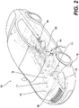
- Figure 2 illustrates the electric vehicle 100 of Figure 1 , with the optical fiber-based sensing membrane 102 removed, according to an example of the present disclosure.
- the battery pack 104 is shown with the sensing membrane 102 removed.
- the battery pack 104 may include, as shown, a plurality of battery cells 200.
- the sensing membrane 102 may be configured to sense thermal and/or strain variations, and/or vibrations associated with one, a few, or all of the battery cells 200 of the battery pack 104.
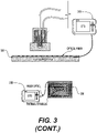
- Figure 3 illustrates a diagrammatic view illustrating the optical fiber-based sensing membrane 102 in use, according to an example of the present disclosure.
- the optical fiber-based sensing membrane 102 may include at least one optical fiber integrated in an adhesive substrate.
- a plurality of optical fibers 300 may be integrated in an adhesive substrate 302.
- sensing membranes may be disposed on upper and lower surfaces of the battery pack 104 in the orientation of Figure 3 .
- the battery pack 104 may include a plurality of battery cells.
- the battery cells may include, in the example shown, a cooling system 304 between upper and lower sets of battery cells in the orientation of Figure 3 .
- the upper and lower sensing membranes, and the battery pack 104 may be enclosed in an enclosure, with upper and lower layers 306 and 308 of the enclosure shown in the orientation of Figure 3 .
- the sensing membrane 102 at 310 may be used to sense thermal and/or strain variations, and/or vibrations of upper battery cells at 312, and the sensing membrane 102 at 314 may be used to sense thermal and/or strain variations, and/or vibrations of lower battery cells at 316.
- the adhesive substrate may include Polyimide, or another such material.
- the Polyimide material may provide the requisite durability with respect to vibrations associated with the battery pack 104 and/or other components that may be engaged with the sensing membrane 102.
- the Polyimide material may provide the requisite durability with respect to temperature variations associated with the battery pack 104 and/or other components, which may be on the order of -40 °C to 140 °C, or include a greater range than -40 °C to 140 °C.
- the Polyimide material may provide the requisite flexibility associated with surface variations associated with the battery pack 104 and/or other components that may be engaged with the sensing membrane 102.
- the Polyimide material may also be transparent, and thus provide sufficient transmission of light into the optical fiber for detection of light or an anomaly (e.g., a high temperature event) associated with the battery pack 104.
- the sensing membrane 102 may be of a light weight (e.g., 200 - 500g/m 2 ). In this regard, the sensing membrane 102 may add minimal weight with respect to the device being monitored for thermal and/or strain variations, and/or vibrations.
- the sensing membrane 102 may be approximately 0.5 mm, to thus minimize integration challenges with respect to the device being monitored for thermal and/or strain variations, and/or vibrations.
- the optical fibers embedded in the sensing membrane 102 may be on the order of 0.25 mm in thickness.
- such optical fibers may be treated after the sensing membrane is assembled, for example, by a combined action of pressure and temperature above the melting point of the optical fiber coating while the sensing membrane material is unaffected.
- the overall thickness of 0.5 mm may thus add minimal thickness associated with the battery pack 104.
- the same process may be applied for the purpose of reducing the micro-bends applied to the fiber at each fiber crossing. The accumulation of thousands of micro-bends may induce attenuation.
- DTS distributed temperature sensing interrogator
- fiber sensing membrane 320 may be utilized to sense temperature, but also strain variations using a distributed strain sensing interrogator in place of the DTS.
- the distributed temperature sensing interrogator 318 which may include an OTDR, may be utilized with the various examples of the sensing membrane 102 as disclosed herein.
- the sensing membrane 102 may provide for monitoring of an entire surface of the battery pack 104.
- the sensing membrane 102 may be dimensioned to monitor a partial or the entire surface of the battery pack 104.
- the sensing membrane 102 may be scalable to measure temperature and/or strain variations, and/or vibrations associated with a small groups of cells. For example, a plurality of sensing membranes may be utilized to measure temperature and/or strain variations, and/or vibrations associated with corresponding groups of cells.
- the sensing membrane 102 may be similarly scalable to measure mechanical damage to the battery cells of the battery pack 104 and/or to the enclosure of the battery pack 104. In this regard, any mechanical damage to the battery cells and/or the enclosure that exceeds a specified amount may be ascertained by the sensing membrane 102 as a strain variation.
- the sensing membrane 102 may be single-ended to include a single optical connector.
- a single optical connector may be connected to a single optical fiber of the sensing membrane 102, where the single optical fiber may be configured in various patterns such as parallel with loop-backs, zig-zag, curved, etc., to cover an entire area of the sensing membrane 102.
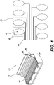
- Figure 4 illustrates a diagrammatic view of the optical fiber-based sensing membrane 102 including a pre-cut membrane, according to an example of the present disclosure.
- the sensing membrane 102 may include, at one or multiple ends thereof, a plurality of pre-cut membranes 400.
- Each of the pre-cut membranes may include an adhesive center 402 that may be removably affixed to areas 404 or 406 of a battery 408.
- the battery 408 may be of a type used for electric vehicles, and may include a planar area 410 and a raised area 412.
- the pre-cut membranes 400 may be staggered so that as the sensing membrane 102 is laid onto the battery 408, the adhesive centers are affixed to the areas, such as the areas 404 or 406.
- the pre-cut membranes 400 may be staggered to facilitate attachment to a plurality of fibers 414 which are looped at 416.
- the fibers 414 may be interconnected to each other, for example, on the left hand side in the orientation of Figure 4 , so that each of the fibers 414 is interconnected to form the sensing membrane 102.
- the entire battery 408 may be covered by a single fiber span including one optical connector.
- the sensing membrane 102 may include a relatively flat configuration to facilitate storage. Further, the relatively flat configuration may provide for maintenance of the modularity of the battery 408.
- Figure 5 illustrates a diagrammatic view of the optical fiber-based sensing membrane 102 including a ribbon configuration, according to an example of the present disclosure.
- the optical fiber-based sensing membrane 102 may be wrapped around a battery 502 in zig-zag manner as shown.
- a single ribbon may be wrapped around four batteries in zig-zag manner as shown.
- Figure 6 illustrates a diagrammatic view of the optical fiber-based sensing membrane 102 including a battery casing as a substrate, according to an example of the present disclosure.
- the optical fiber-based sensing membrane 102 may utilize a battery casing as a substrate.
- an optical fiber 600 may be adhered or laminated to a surface of a battery casing housing 602, irrespective of the material of the battery casing housing, or molded directly into the battery casing housing (in the case of a plastic or composite material of the battery casing housing).
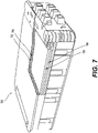
- Figures 7 illustrates an example of a pouch cell module, according to an example of the present disclosure.
- Figure 8 illustrates normal and bulging states of the pouch cell module of Figure 7 , and detection of bulging of the pouch cell module by utilization of the sensing membrane 102 or an optical fiber, according to an example of the present disclosure.
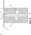
- Figures 9 and 10 illustrate other examples of deformation of the pouch cell module, and detection of bulging of the pouch cell module by utilization of the sensing membrane 102 or an optical fiber, according to an example of the present disclosure.
- strain monitoring may allow for detection of the production of gases in a device, such as a battery cell, and more specifically, a pouch cell module.
- the associated swelling of the battery cell with inner pressure may result from a failure, and its early detection may prevent a subsequent thermal runaway.
- the sensing membrane 102 in one example, the optical fiber in the sensing membrane 102 or an optical fiber may not be integrated in the battery cell assembly process and further, in a device, such as a pouch cell module (avoiding the optical connections to get in and out of the pouch cell module).
- the sensing membrane 102 (or an optical fiber itself as disclosed herein) may be utilized to detect pressure outside of a pouch cell module.
- free space may be available in some types of pouch cell modules, such as the pouch cell module 700, that are heat sealed and therefore narrower on three edges, and possibly in two orthogonal dimensions.
- the sensing membrane 102 (or an optical fiber itself as disclosed herein) may be utilized to measure the pressure outside the pouch cell module 700.
- pouches 702 filled with a liquid may be placed in the free space of the pouch cell module 700 between pouch cells 704.
- Figure 7 shows a cutout view that illustrates pouches 702 (cutout and complete), and pouch cells 704 (cutout and complete), each of which alternate in the pouch cell module 700.
- the pouches may expand under the action of pressure and protrude, for example, at 804, outside the pouch cell module through a dedicated window 806 of the housing.
- the sensing membrane 102 (or an optical fiber itself as disclosed herein) may be disposed at the dedicated window 806 to measure strain from expansion of a pouch.
- a pouch cell module 900 including pouch cells 902 may include a specifically profiled (e.g., curved) plate 904 placed in free space between the pouch cells 902.
- transverse pressure on the plate 904 in the direction of arrows 906 and 908 e.g., due to thermal expansion of the pouch cells 902 may expand the plate 904 in a longitudinal direction at 908 so as to protrude outside the pouch cell module through a dedicated casing window 910.
- an expansion on the order of 10% may be accessible to allow a movement in the centimeter scale.
- the sensing membrane 102 (or an optical fiber itself as disclosed herein) may be disposed at the dedicated window 910 to measure strain from expansion of the plate 904.
- the example of Figure 10 may implement the principle that the battery-pouch alone may expand enough and actuate a piston 1000 or any mechanism that would protrude outside the pouch cell module 1002.
- a pouch 1004 may be optimized (e.g., include an enlarged area as shown) to enhance the expansion at the target location to actuate the expected movement and bending loss on the optical fiber of the sensing membrane 102 (or an optical fiber itself in place of the sensing membrane 102 as disclosed herein).
- the pouch 1004 may similarly expand upwards in the orientation of Figure 10 to push piston 1000 upwards, where the strain induced in the optical fiber of the sensing membrane 102 (or an optical fiber itself in place of the sensing membrane 102 as disclosed herein) may be sensed as disclosed herein.
- displacement may be used to press down on a mechanical device installed in the cover of the pouch cell module.
- the sensing membrane 102 or an optical fiber itself may be placed in a dedicated path (e.g., a groove) as shown in Figures 7-10 .
- the sensing membrane 102 may be formed of a coating (e.g., 900 ⁇ m buffer) around an optical fiber, or the optical fiber including a coating (e.g., 900 ⁇ m buffer) may be disposed in a polyimide ribbon, and circulated among all of the pouches and pouch cell modules.
- the optical fiber may be spliced in series after the sensing membrane 102 so that the optical fiber may be monitored with the same reflectometer probing the sensing membrane 102.
- the movement of the protruding pressure pouch or plate may force the optical fiber (or the sensing membrane 102) into a bend that is calibrated, and will be detected as a loss on the reflectometric trace.
- Different bend amounts may represent different loss types (e.g., a first bend amount may represent a first type of thermal event, a second bend amount may represent a second type of thermal event, etc.).
- a moderate spatial resolution on the OTDR may be used to detect which pouch cell module has a bulging pouch and take the appropriate preventive action. Different preventive actions may correspond to different bend amounts.
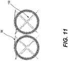
- Figure 11 illustrates a thermal diffuser for utilization with the optical fiber-based sensing membrane 102, according to an example of the present disclosure.
- the optical fiber-based sensing membrane 102 may enhance the ability to detect a parameter that may be very localized by conveying that parameter to the fiber location.
- a thermal diffuser 1100 may be applied to transfer the heat from areas not covered by the fiber (e.g., the optical fibers 300 of Figure 3 ).
- a copper diffuser or a thermally conductive electrically insulating material may be used.
Landscapes
- Physics & Mathematics (AREA)
- General Physics & Mathematics (AREA)
- Engineering & Computer Science (AREA)
- Chemical & Material Sciences (AREA)
- Manufacturing & Machinery (AREA)
- Chemical Kinetics & Catalysis (AREA)
- Electrochemistry (AREA)
- General Chemical & Material Sciences (AREA)
- Life Sciences & Earth Sciences (AREA)
- Sustainable Development (AREA)
- Sustainable Energy (AREA)
- Power Engineering (AREA)
- Transportation (AREA)
- Mechanical Engineering (AREA)
- Optics & Photonics (AREA)
- Microelectronics & Electronic Packaging (AREA)
- Analytical Chemistry (AREA)
- Length Measuring Devices By Optical Means (AREA)
- Light Guides In General And Applications Therefor (AREA)
- Measuring Temperature Or Quantity Of Heat (AREA)
Abstract
Description
- This application claims priority to commonly assigned and co-pending European Patent Application No.
EP21305505.6, filed April 16, 2021 EP21305506.4, filed April 16, 2021 - Optical fibers may be utilized in various industries such as communications, medical, military, broadcast, etc., to transmit data and for other related applications. Examples of applications may include sensing of temperature, mechanical strain, vibrations, and/or radiation dosage by utilizing an optical fiber. In this regard, principles of Raman, Rayleigh, and/or Brillouin scattering may be implemented for sensing of the temperature, mechanical strain, vibrations, and/or radiation dosage.
- According to a first aspect, there is provided, an optical fiber-based sensing membrane comprising: at least one optical fiber; and a substrate, wherein the at least one optical fiber is integrated in the substrate, the substrate includes a thickness and a material property, and the thickness and the material property are specified to ascertain, via the at least one optical fiber and for a device that is contiguously engaged with a surface of the substrate, includes the substrate embedded in the device, or includes the surface of the substrate at a predetermined distance from the device, at least one of a thermal or a mechanical property associated with the device, or a radiation level associated with a device environment.
- The device may include a battery pack of an electric vehicle.
- The mechanical property may include at least one of strain or vibration.
- The substrate may include Polyimide.
- The at least one optical fiber and the substrate may include a combined weight of between approximately 200 g/m2 to 500g/m2.
- The at least one optical fiber and the substrate may include a combined thickness of less than approximately 0.5 mm.
- The at least one optical fiber may include a single optical fiber that is looped.
- The optical fiber-based sensing membrane may further comprise a thermal diffuser to transfer heat from an area of the device that is not monitored by the optical fiber-based sensing membrane to an area that is monitored by the optical fiber-based sensing membrane.
- According to a second aspect, there is provided an optical fiber-based sensing membrane comprising: at least one optical fiber; and a substrate, wherein the at least one optical fiber is integrated in the substrate, the substrate includes a thickness and a material property, and the thickness and the material property are specified to ascertain, via the at least one optical fiber, at least one of a thermal or a mechanical property associated with a device.
- The device may include a battery pack of an electric vehicle.
- The substrate may include the at least one optical fiber is formed as a ribbon to wrap around the device.
- The substrate may include the at least one optical fiber is formed in a three-dimensional (3D) shape to at least partially encase the device.
- According to a third aspect, there is provided a method comprising: embedding an optical fiber-based sensing membrane in a device or contiguously engaging the optical fiber-based sensing membrane with the device, wherein the optical fiber-based sensing membrane includes: at least one optical fiber; and a substrate, wherein the at least one optical fiber is integrated in the substrate, and the substrate includes a thickness and a material property; and ascertaining, via the embedded or the contiguously-engaged optical fiber-based sensing membrane, at least one of a thermal or a mechanical property associated with the device.
- The device may include a battery pack of an electric vehicle.
- The device may include a pouch cell module that includes at least one pouch that expands or contracts based on thermal changes in the pouch cell module, and wherein ascertaining, via the embedded or the contiguously-engaged optical fiber-based sensing membrane, the at least one of the thermal or the mechanical property associated with the device may further comprise: ascertaining, via the contiguously-engaged optical fiber-based sensing membrane, the mechanical property that includes strain based on expansion of the at least one pouch due to thermal changes associated with the device.
- The device may include a pouch cell module that includes at least one plate that expands based on thermal changes in the pouch cell module, and wherein ascertaining, via the embedded or the contiguously-engaged optical fiber-based sensing membrane, the at least one of the thermal or the mechanical property associated with the device may further comprise: ascertaining, via the contiguously-engaged optical fiber-based sensing membrane, the mechanical property that includes strain based on expansion of the at least one plate due to thermal changes associated with the device.
- The at least one plate may include a curved profile.
- The device may include a pouch cell module that includes at least one piston that moves based on thermal changes in the pouch cell module, and wherein ascertaining, via the embedded or the contiguously-engaged optical fiber-based sensing membrane, the at least one of the thermal or the mechanical property associated with the device may further comprise: ascertaining, via the contiguously-engaged optical fiber-based sensing membrane, the mechanical property that includes strain based on movement of the at least one piston due to thermal changes associated with the device.
- Ascertaining, via the contiguously-engaged optical fiber-based sensing membrane, the mechanical property that includes strain based on movement of the at least one piston due to thermal changes associated with the device may further comprise: ascertaining, via the contiguously-engaged optical fiber-based sensing membrane, the mechanical property that includes strain based on movement of the at least one piston resulting from expansion of an associated pouch due to thermal changes associated with the device.
- The method may further comprise: utilizing a thermal diffuser to transfer heat from an area of the device that is not monitored by the optical fiber-based sensing membrane to an area that is monitored by the optical fiber-based sensing membrane.
- Features of the present disclosure are illustrated by way of examples shown in the following figures. In the following figures, like numerals indicate like elements, in which:
-
Figure 1 illustrates an electric vehicle including an optical fiber-based sensing membrane, according to an example of the present disclosure; -
Figure 2 illustrates the electric vehicle ofFigure 1 , with the optical fiber-based sensing membrane removed, according to an example of the present disclosure; -
Figure 3 illustrates a diagrammatic view illustrating the optical fiber-based sensing membrane ofFigure 1 in use, according to an example of the present disclosure; -
Figure 4 illustrates a diagrammatic view of the optical fiber-based sensing membrane ofFigure 1 including a pre-cut membrane, according to an example of the present disclosure; -
Figure 5 illustrates a diagrammatic view of the optical fiber-based sensing membrane ofFigure 1 including a ribbon configuration, according to an example of the present disclosure; -
Figure 6 illustrates a diagrammatic view of the optical fiber-based sensing membrane ofFigure 1 including a battery casing as a substrate, according to an example of the present disclosure; -
Figures 7 illustrates an example of a pouch cell module, according to an example of the present disclosure; -
Figure 8 illustrates normal and bulging states of the pouch cell module ofFigure 7 , and detection of bulging of the pouch cell module by utilization of the optical fiber-based sensing membrane ofFigure 1 or an optical fiber, according to an example of the present disclosure; -
Figures 9 and10 illustrate other examples of deformation of the pouch cell module, and detection of bulging of the pouch cell module by utilization of the optical fiber-based sensing membrane ofFigure 1 or an optical fiber, according to an example of the present disclosure; and -
Figure 11 illustrates a thermal diffuser for utilization with the optical fiber-based sensing membrane ofFigure 1 , according to an example of the present disclosure. - For simplicity and illustrative purposes, the present disclosure is described by referring mainly to examples thereof. In the following description, details are set forth in order to provide an understanding of the present disclosure. It will be readily apparent however, that the present disclosure may be practiced without limitation to these details. In other instances, some methods and structures have not been described in detail so as not to unnecessarily obscure the present disclosure.
- Throughout the present disclosure, the terms "a" and "an" are intended to denote at least one of a particular element. As used herein, the term "includes" means includes but not limited to, the term "including" means including but not limited to. The term "based on" means based at least in part on.
- According to examples disclosed herein, the optical fiber-based sensing membrane may include at least one optical fiber, and a flexible substrate. The at least one optical fiber may be integrated in the flexible substrate. The flexible substrate may include a thickness and a material property that are specified to ascertain, via the at least one optical fiber and for a device that is contiguously engaged with a surface of the flexible substrate, includes the flexible substrate embedded in the device, or includes the surface of the flexible substrate at a predetermined distance from the device, a thermal and/or a mechanical property associated with the device. Examples of mechanical properties may include strain, vibration, and other such properties. The device may include, for example, a battery pack of an electric vehicle, or any other type of flat or curved structure that is to be monitored. Applications may include and not be limited to the monitoring of an energy storage plant based on batteries, monitoring of a nuclear power plant, and monitoring of defense equipment. Yet further, the substrate may be flexible or rigid. For example, with respect to a surface application of the sensing membrane on a device or an embedded application of the sensing membrane in a device, the optical fiber may be embedded in a rigid sensing membrane formed of a rigid substrate. According to another example, with respect to an optical fiber integrated in a molded part of a device such as a battery pack, the optical fiber may be embedded in a rigid sensing membrane formed of a rigid substrate.
- With respect to fiber sensing generally, in some applications, an optical fiber may be utilized to monitor thermal and/or mechanical properties of a device. The device as utilized herein may be any type of machine, component, structure, etc., that is to be monitored. For example, for a device such as an electric vehicle battery pack that includes a plurality of battery cells, an optical fiber may be utilized to monitor thermal and/or mechanical properties of the battery pack. In this regard, embedding of an optical fiber directly into the device may not be feasible due to technical challenges related, for example, to laying, coiling, and/or attaching optical connectors each time an independent element (e.g., battery cell of the battery pack) of the device needs to be addressed.
- In order to address at least the aforementioned technical challenges, the optical fiber-based sensing membrane disclosed herein may include at least one optical fiber integrated in a flexible substrate. According to examples disclosed herein, the optical fiber-based sensing membrane may utilize, for example, a Polyimide flex, or other such materials. In this regard, the optical fiber-based sensing membrane may also house components such as electrical tracks, sensors, and optical connectors to reduce an electrical harness associated with utilization of the optical fiber-based sensing membrane.
- According to examples disclosed herein, the optical fiber-based sensing membrane may include various types of layouts. For example, the layouts may include single or multiple optical fibers, single-end or dual-end access to the optical fibers, and other types of layouts. A complete and perfect path folding may be achieved, for example, with a multicore fiber and a loopback optical element connecting the two cores in series at a distal end from an interrogator.
- According to examples disclosed herein, the optical fiber-based sensing membrane may include fiber loops to compensate for spatial resolution. Alternatively or additionally, the optical fiber-based sensing membrane may include path folding or partial path folding to compensate for optical fiber losses.
- According to examples disclosed herein, the optical fiber-based sensing membrane may sense various types of parameters associated with a device. For example, the parameters may include temperature, strain, vibration, radiation dosage and other such parameters.
- According to examples disclosed herein, the optical fiber-based sensing membrane may enhance the ability to detect a parameter that may be very localized by conveying that parameter to the fiber location. For example, in the case of detection of a local hotspot with the fiber loop configuration, a thermal diffuser may be applied to transfer the heat from areas not covered by the fiber. Depending on application constraints, a copper diffuser or a thermally conductive electrically insulating material may be used.
- According to examples disclosed herein, different types of parameters sensed by the optical fiber-based sensing membrane may be used to generate different types of notifications or alarms. For example, a temperature variation that exceeds a specified temperature threshold may be used to generate a first type of notification or alarm. Similarly, a strain variation that exceeds a specified strain threshold (e.g., due to damage to the device) may be used to generate a second type of notification or alarm. The occurrence of thermal runaway of a battery element may also be classified through the analysis of the temporal evolution and in particular the rate of change of temperature or strain.
- According to examples disclosed herein, a number of elements of the device being monitored may be scaled without the need to add optical connections. For example, a length or configuration of the optical fiber-based sensing membrane may be modified as needed to account for an increased or a decreased number of elements being monitored. In this regard, one or more optical connections may be utilized for an optical fiber-based sensing membrane, and a size of the optical fiber-based sensing membrane may be increased or decreased as needed to address a plurality of devices, without the need to include an optical connection for each device. Thus a single optical connection may be implemented for a plurality of devices being monitored, thus reducing the potential of a fault associated with operation of the optical fiber-based sensing membrane.
- According to examples disclosed herein, the devices that are being monitored may remain accessible, for example, for maintenance and other such activities, without being restricted by optics associated with the optical fiber-based sensing membrane. For example, the optical fiber-based sensing membrane may be configured to address a specified area of the device being monitored, leaving other areas of the device accessible for maintenance and other activities.
- According to examples disclosed herein, the optical fiber-based sensing membrane may itself remain accessible, for example, for maintenance and other such activities. In this regard, the optical fiber-based sensing membrane may be configured to address a specified area of the device being monitored, leaving other areas of the optical fiber-based sensing membrane accessible for maintenance and other activities.
- According to examples disclosed herein, the optical fiber-based sensing membrane may be implemented in a relatively harsh environment. For example, the environment of the optical fiber-based sensing membrane may include relatively significant temperature variations on the order of -40 °C to 140 °C. The material used for the sensing membrane may supersede the standard coating of optical fibers and continue to protect the optical fiber mechanically beyond the melting point of coating.
- According to examples disclosed herein, the optical fiber-based sensing membrane may include a two-dimensional or a three-dimensional configuration. The two-dimensional configuration may include a plurality of optical fibers embedded in a substrate and configured as a two-dimensional plane structure to match a corresponding two-dimensional surface of a device that is to be monitored for temperature and/or strain variations, vibrations, and/or radiation dosage. The three-dimensional configuration may include a plurality of optical fibers embedded in a substrate and configured as a three-dimensional structure to match a corresponding three-dimensional shape of a device that is to be monitored for temperature and/or strain variations, vibrations, and/or radiation dosage. Depending on the dimensions of the structure to be monitored, the budget loss of the fiber system and the dynamic range of the interrogator, distances may be covered in a single chain, or with multiple fibers in parallel that may be accessed sequentially from a single interrogator by means of an optical switch.
- According to examples disclosed herein, the optical fiber-based sensing membrane may be utilized with an optical time-domain reflectometer (OTDR) to determine temperature, strain and/or radiation dosage associated with a device. The OTDR may represent an optoelectronic instrument used to characterize an optical fiber, for example, of the optical fiber-based sensing membrane. The OTDR may inject a series of optical pulses into an optical fiber under test. Based on the injected optical pulses, the OTDR may extract, from the same end of the optical fiber in which the optical pulses are injected, light that is scattered or reflected back from points along the optical fiber. The scattered or reflected light that is gathered back may be used to characterize the optical fiber. For example, the scattered or reflected light that is gathered back may be used to detect, locate, and measure events at any location of the optical fiber. The events may include faults at any location of the optical fiber. Other types of features that may be measured by the OTDR include attenuation uniformity and attenuation rate, segment length, and location and insertion loss of connectors and splices.
- The OTDR may be used to determine both Brillouin and Rayleigh traces for an optical fiber, for example, of the optical fiber-based sensing membrane. In one example, in an initial acquisition, Brillouin frequency shift and Brillouin power may be used to implement an absolute referencing of a Rayleigh reference trace (or traces). The Rayleigh reference trace may represent a reference point for subsequent measurements of the Rayleigh frequency shift. In this regard, the absolute referencing of the Rayleigh reference trace (or traces) may then be used to determine temperature and/or strain associated with an optical fiber by using the Brillouin frequency shift and the Rayleigh frequency shift in subsequent acquisitions.
- According to examples disclosed herein, the optical fiber-based sensing membrane may be utilized with the OTDR to determine, based on distributed measurement, temperature, strain, and/or vibrations associated with a device, such as a battery pack.
- According to examples disclosed herein, an optical fiber-based sensing membrane may include at least one optical fiber, and a substrate. The at least one optical fiber may be integrated in the substrate, and the substrate may include a thickness and a material property. The thickness and the material property may be specified to ascertain, via the at least one optical fiber and for a device that is contiguously engaged with a surface of the substrate, includes the substrate embedded in the device, or includes the surface of the substrate at a predetermined distance from the device, a thermal and/or a mechanical property associated with the device, or a radiation level associated with a device environment.
- For the optical fiber-based sensing membrane described above, the device may include a battery pack of an electric vehicle.
- For the optical fiber-based sensing membrane described above, the mechanical property may include strain and/or vibration.
- For the optical fiber-based sensing membrane described above, the substrate may include Polyimide.
- For the optical fiber-based sensing membrane described above, the at least one optical fiber and the substrate may include a combined weight of between approximately 200 g/m2 to 500g/m2.
- For the optical fiber-based sensing membrane described above, the at least one optical fiber and the substrate may include a combined thickness of less than approximately 0.5 mm.
- For the optical fiber-based sensing membrane described above, the at least one optical fiber may include a single optical fiber that is looped.
- For the optical fiber-based sensing membrane described above, a thermal diffuser may transfer heat from an area of the device that is not monitored by the optical fiber-based sensing membrane to an area that is monitored by the optical fiber-based sensing membrane.
- According to examples disclosed herein, an optical fiber-based sensing membrane may include at least one optical fiber, and a substrate. The at least one optical fiber may be integrated in the substrate, and the substrate may include a thickness and a material property. The thickness and the material property may be specified to ascertain, via the at least one optical fiber, a thermal and/or a mechanical property associated with a device.
- For the optical fiber-based sensing membrane described above, the substrate including the at least one optical fiber may be formed as a ribbon to wrap around the device.
- For the optical fiber-based sensing membrane described above, the substrate including the at least one optical fiber may be formed in a three-dimensional (3D) shape to at least partially encase the device.
- According to examples disclosed herein, a method may include embedding an optical fiber-based sensing membrane in a device or contiguously engaging the optical fiber-based sensing membrane with the device. The optical fiber-based sensing membrane may include at least one optical fiber, and a substrate. The at least one optical fiber may be integrated in the substrate, and the substrate may include a thickness and a material property. The method may further include ascertaining, via the embedded or the contiguously-engaged optical fiber-based sensing membrane, a thermal and/or a mechanical property associated with the device.
- For the method described above, the device may include a pouch cell module that includes at least one pouch that expands or contracts based on thermal changes in the pouch cell module. In this regard, ascertaining, via the embedded or the contiguously-engaged optical fiber-based sensing membrane, the thermal and/or the mechanical property associated with the device may further include ascertaining, via the contiguously-engaged optical fiber-based sensing membrane, the mechanical property that includes strain based on expansion of the at least one pouch due to thermal changes associated with the device.
- For the method described above, the device may include a pouch cell module that includes at least one plate that expands based on thermal changes in the pouch cell module. In this regard, ascertaining, via the embedded or the contiguously-engaged optical fiber-based sensing membrane, the thermal and/or the mechanical property associated with the device may further include ascertaining, via the contiguously-engaged optical fiber-based sensing membrane, the mechanical property that includes strain based on expansion of the at least one plate due to thermal changes associated with the device. The plate may include a curved profile.
- For the method described above, the device may include a pouch cell module that includes at least one piston that moves based on thermal changes in the pouch cell module. In this regard, ascertaining, via the embedded or the contiguously-engaged optical fiber-based sensing membrane, the thermal and/or the mechanical property associated with the device may further include ascertaining, via the contiguously-engaged optical fiber-based sensing membrane, the mechanical property that includes strain based on movement of the at least one piston due to thermal changes associated with the device. In this regard, the mechanical property may include strain based on movement of the at least one piston resulting from expansion of an associated pouch due to thermal changes associated with the device.
- For the method described above, the method may further include utilizing a thermal diffuser to transfer heat from an area of the device that is not monitored by the optical fiber-based sensing membrane to an area that is monitored by the optical fiber-based sensing membrane.
-
Figure 1 illustrates anelectric vehicle 100 including an optical fiber-based sensing membrane 102 (hereinafter referred to as "sensingmembrane 102"), according to an example of the present disclosure. Referring toFigure 1 , theelectric vehicle 100 may include thesensing membrane 102 disposed on a device, such as abattery pack 104. - The
electric vehicle 100 may include other known components such as athermal system 106 for cooling the vehicle, anauxiliary battery 108, anonboard battery charger 110, avehicle transmission 112, acharge port 114 for thebattery pack 104, aconverter 116, apower electronics controller 118, and anelectric traction motor 120. -
Figure 2 illustrates theelectric vehicle 100 ofFigure 1 , with the optical fiber-basedsensing membrane 102 removed, according to an example of the present disclosure. - Referring to
Figure 2 , thebattery pack 104 is shown with thesensing membrane 102 removed. In this regard, thebattery pack 104 may include, as shown, a plurality ofbattery cells 200. Thesensing membrane 102 may be configured to sense thermal and/or strain variations, and/or vibrations associated with one, a few, or all of thebattery cells 200 of thebattery pack 104. -
Figure 3 illustrates a diagrammatic view illustrating the optical fiber-basedsensing membrane 102 in use, according to an example of the present disclosure. - Referring to
Figure 3 , the optical fiber-basedsensing membrane 102 may include at least one optical fiber integrated in an adhesive substrate. In the example ofFigure 3 , as shown in the enlarged view, a plurality ofoptical fibers 300 may be integrated in anadhesive substrate 302. - In the example of
Figure 3 , sensing membranes may be disposed on upper and lower surfaces of thebattery pack 104 in the orientation ofFigure 3 . Thebattery pack 104 may include a plurality of battery cells. The battery cells may include, in the example shown, acooling system 304 between upper and lower sets of battery cells in the orientation ofFigure 3 . The upper and lower sensing membranes, and thebattery pack 104 may be enclosed in an enclosure, with upper andlower layers Figure 3 . - For the example of
Figure 3 , thesensing membrane 102 at 310 may be used to sense thermal and/or strain variations, and/or vibrations of upper battery cells at 312, and thesensing membrane 102 at 314 may be used to sense thermal and/or strain variations, and/or vibrations of lower battery cells at 316. - The adhesive substrate may include Polyimide, or another such material. The Polyimide material may provide the requisite durability with respect to vibrations associated with the
battery pack 104 and/or other components that may be engaged with thesensing membrane 102. Similarly, the Polyimide material may provide the requisite durability with respect to temperature variations associated with thebattery pack 104 and/or other components, which may be on the order of -40 °C to 140 °C, or include a greater range than -40 °C to 140 °C. Further, the Polyimide material may provide the requisite flexibility associated with surface variations associated with thebattery pack 104 and/or other components that may be engaged with thesensing membrane 102. The Polyimide material may also be transparent, and thus provide sufficient transmission of light into the optical fiber for detection of light or an anomaly (e.g., a high temperature event) associated with thebattery pack 104. - The
sensing membrane 102 may be of a light weight (e.g., 200 - 500g/m2). In this regard, thesensing membrane 102 may add minimal weight with respect to the device being monitored for thermal and/or strain variations, and/or vibrations. - The
sensing membrane 102 may be approximately 0.5 mm, to thus minimize integration challenges with respect to the device being monitored for thermal and/or strain variations, and/or vibrations. In this regard, the optical fibers embedded in thesensing membrane 102 may be on the order of 0.25 mm in thickness. For the geometric patterns of optical fibers that include optical fiber crossings, such optical fibers may be treated after the sensing membrane is assembled, for example, by a combined action of pressure and temperature above the melting point of the optical fiber coating while the sensing membrane material is unaffected. Thus, the overall thickness of 0.5 mm may thus add minimal thickness associated with thebattery pack 104. The same process may be applied for the purpose of reducing the micro-bends applied to the fiber at each fiber crossing. The accumulation of thousands of micro-bends may induce attenuation. - With continued reference to
Figure 3 , one example of a test set-up to evaluate performances of distributed temperature sensing systems based on distributed temperature sensing interrogator (DTS) 318 (also referred to herein as distributed temperature sensor) andfiber sensing membrane 320 is shown, and may be utilized to sense temperature, but also strain variations using a distributed strain sensing interrogator in place of the DTS. In this regard, the distributedtemperature sensing interrogator 318, which may include an OTDR, may be utilized with the various examples of thesensing membrane 102 as disclosed herein. - The
sensing membrane 102 may provide for monitoring of an entire surface of thebattery pack 104. In this regard, thesensing membrane 102 may be dimensioned to monitor a partial or the entire surface of thebattery pack 104. - The
sensing membrane 102 may be scalable to measure temperature and/or strain variations, and/or vibrations associated with a small groups of cells. For example, a plurality of sensing membranes may be utilized to measure temperature and/or strain variations, and/or vibrations associated with corresponding groups of cells. - The
sensing membrane 102 may be similarly scalable to measure mechanical damage to the battery cells of thebattery pack 104 and/or to the enclosure of thebattery pack 104. In this regard, any mechanical damage to the battery cells and/or the enclosure that exceeds a specified amount may be ascertained by thesensing membrane 102 as a strain variation. - The
sensing membrane 102 may be single-ended to include a single optical connector. In this regard, a single optical connector may be connected to a single optical fiber of thesensing membrane 102, where the single optical fiber may be configured in various patterns such as parallel with loop-backs, zig-zag, curved, etc., to cover an entire area of thesensing membrane 102. -
Figure 4 illustrates a diagrammatic view of the optical fiber-basedsensing membrane 102 including a pre-cut membrane, according to an example of the present disclosure. - Referring to
Figure 4 , according to examples disclosed herein, thesensing membrane 102 may include, at one or multiple ends thereof, a plurality ofpre-cut membranes 400. Each of the pre-cut membranes may include anadhesive center 402 that may be removably affixed toareas battery 408. Thebattery 408 may be of a type used for electric vehicles, and may include aplanar area 410 and a raisedarea 412. In the example ofFigure 4 , thepre-cut membranes 400 may be staggered so that as thesensing membrane 102 is laid onto thebattery 408, the adhesive centers are affixed to the areas, such as theareas pre-cut membranes 400 may be staggered to facilitate attachment to a plurality offibers 414 which are looped at 416. Thefibers 414 may be interconnected to each other, for example, on the left hand side in the orientation ofFigure 4 , so that each of thefibers 414 is interconnected to form thesensing membrane 102. In this regard, theentire battery 408 may be covered by a single fiber span including one optical connector. Thesensing membrane 102 may include a relatively flat configuration to facilitate storage. Further, the relatively flat configuration may provide for maintenance of the modularity of thebattery 408. -
Figure 5 illustrates a diagrammatic view of the optical fiber-basedsensing membrane 102 including a ribbon configuration, according to an example of the present disclosure. - Referring to
Figure 5 , for aribbon configuration 500, the optical fiber-basedsensing membrane 102 may be wrapped around abattery 502 in zig-zag manner as shown. For example, a single ribbon may be wrapped around four batteries in zig-zag manner as shown. -
Figure 6 illustrates a diagrammatic view of the optical fiber-basedsensing membrane 102 including a battery casing as a substrate, according to an example of the present disclosure. - Referring to
Figure 6 , according to examples disclosed herein, the optical fiber-basedsensing membrane 102 may utilize a battery casing as a substrate. In this regard, anoptical fiber 600 may be adhered or laminated to a surface of abattery casing housing 602, irrespective of the material of the battery casing housing, or molded directly into the battery casing housing (in the case of a plastic or composite material of the battery casing housing). -
Figures 7 illustrates an example of a pouch cell module, according to an example of the present disclosure.Figure 8 illustrates normal and bulging states of the pouch cell module ofFigure 7 , and detection of bulging of the pouch cell module by utilization of thesensing membrane 102 or an optical fiber, according to an example of the present disclosure.Figures 9 and10 illustrate other examples of deformation of the pouch cell module, and detection of bulging of the pouch cell module by utilization of thesensing membrane 102 or an optical fiber, according to an example of the present disclosure. - Referring next to
Figures 7-9 , strain monitoring may allow for detection of the production of gases in a device, such as a battery cell, and more specifically, a pouch cell module. The associated swelling of the battery cell with inner pressure may result from a failure, and its early detection may prevent a subsequent thermal runaway. With respect to thesensing membrane 102, in one example, the optical fiber in thesensing membrane 102 or an optical fiber may not be integrated in the battery cell assembly process and further, in a device, such as a pouch cell module (avoiding the optical connections to get in and out of the pouch cell module). In this regard, the sensing membrane 102 (or an optical fiber itself as disclosed herein) may be utilized to detect pressure outside of a pouch cell module. - Referring to
Figure 7 , free space may be available in some types of pouch cell modules, such as thepouch cell module 700, that are heat sealed and therefore narrower on three edges, and possibly in two orthogonal dimensions. In this regard, the sensing membrane 102 (or an optical fiber itself as disclosed herein) may be utilized to measure the pressure outside thepouch cell module 700. In one example,pouches 702 filled with a liquid may be placed in the free space of thepouch cell module 700 betweenpouch cells 704. In this regard,Figure 7 shows a cutout view that illustrates pouches 702 (cutout and complete), and pouch cells 704 (cutout and complete), each of which alternate in thepouch cell module 700. - As shown in
Figure 8 that illustrates a normal state at 800 and a bulging state at 802 of thepouch cell module 700, the pouches may expand under the action of pressure and protrude, for example, at 804, outside the pouch cell module through adedicated window 806 of the housing. In this regard, the sensing membrane 102 (or an optical fiber itself as disclosed herein) may be disposed at thededicated window 806 to measure strain from expansion of a pouch. - In another example, as shown in
Figure 9 , apouch cell module 900 including pouch cells 902 may include a specifically profiled (e.g., curved)plate 904 placed in free space between the pouch cells 902. In this case, transverse pressure on theplate 904 in the direction ofarrows 906 and 908 (e.g., due to thermal expansion of the pouch cells 902) may expand theplate 904 in a longitudinal direction at 908 so as to protrude outside the pouch cell module through adedicated casing window 910. For theplate 904, an expansion on the order of 10% may be accessible to allow a movement in the centimeter scale. The sensing membrane 102 (or an optical fiber itself as disclosed herein) may be disposed at thededicated window 910 to measure strain from expansion of theplate 904. - Referring to
Figure 10 , the example ofFigure 10 may implement the principle that the battery-pouch alone may expand enough and actuate apiston 1000 or any mechanism that would protrude outside thepouch cell module 1002. Apouch 1004 may be optimized (e.g., include an enlarged area as shown) to enhance the expansion at the target location to actuate the expected movement and bending loss on the optical fiber of the sensing membrane 102 (or an optical fiber itself in place of thesensing membrane 102 as disclosed herein). Thus, whenpouch cells 1006 expand, thepouch 1004 may similarly expand upwards in the orientation ofFigure 10 to pushpiston 1000 upwards, where the strain induced in the optical fiber of the sensing membrane 102 (or an optical fiber itself in place of thesensing membrane 102 as disclosed herein) may be sensed as disclosed herein. In the event that the pouch cell is deformed from above in the orientation ofFigure 10 , displacement may be used to press down on a mechanical device installed in the cover of the pouch cell module. - With respect to the examples of
Figures 7-10 , outside the pouch, and in front of the pressure conveying component, thesensing membrane 102 or an optical fiber itself (e.g., without thesensing membrane 102, or in series after the sensing membrane 102) may be placed in a dedicated path (e.g., a groove) as shown inFigures 7-10 . Thesensing membrane 102 may be formed of a coating (e.g., 900µm buffer) around an optical fiber, or the optical fiber including a coating (e.g., 900µm buffer) may be disposed in a polyimide ribbon, and circulated among all of the pouches and pouch cell modules. In one example that uses the optical fiber itself, the optical fiber may be spliced in series after thesensing membrane 102 so that the optical fiber may be monitored with the same reflectometer probing thesensing membrane 102. The movement of the protruding pressure pouch or plate may force the optical fiber (or the sensing membrane 102) into a bend that is calibrated, and will be detected as a loss on the reflectometric trace. Different bend amounts may represent different loss types (e.g., a first bend amount may represent a first type of thermal event, a second bend amount may represent a second type of thermal event, etc.). A moderate spatial resolution on the OTDR may be used to detect which pouch cell module has a bulging pouch and take the appropriate preventive action. Different preventive actions may correspond to different bend amounts. -
Figure 11 illustrates a thermal diffuser for utilization with the optical fiber-basedsensing membrane 102, according to an example of the present disclosure. - Referring to
Figures 1 and11 , the optical fiber-basedsensing membrane 102 may enhance the ability to detect a parameter that may be very localized by conveying that parameter to the fiber location. For example, in the case of detection of a local hotspot with the fiber loop configuration, athermal diffuser 1100 may be applied to transfer the heat from areas not covered by the fiber (e.g., theoptical fibers 300 ofFigure 3 ). Depending on application constraints, a copper diffuser or a thermally conductive electrically insulating material may be used. - What has been described and illustrated herein is an example along with some of its variations. The terms, descriptions and figures used herein are set forth by way of illustration only and are not meant as limitations. Many variations are possible within the spirit and scope of the subject matter, which is intended to be defined by the following claims -- and their equivalents -- in which all terms are meant in their broadest reasonable sense unless otherwise indicated.
Claims (15)
- An optical fiber-based sensing membrane comprising:at least one optical fiber; anda substrate, whereinthe at least one optical fiber is integrated in the substrate,the substrate includes a thickness and a material property, andthe thickness and the material property are specified to ascertain, via the at least one optical fiber and for a device that iscontiguously engaged with a surface of the substrate,includes the substrate embedded in the device, orincludes the surface of the substrate at a predetermined distance from the device,at least one of a thermal or a mechanical property associated with the device, or a radiation level associated with a device environment.
- The optical fiber-based sensing membrane according to claim 1, wherein the device includes a battery pack of an electric vehicle.
- The optical fiber-based sensing membrane according to claim 1, wherein the mechanical property includes at least one of strain or vibration.
- The optical fiber-based sensing membrane according to claim 1, wherein the substrate includes Polyimide.
- The optical fiber-based sensing membrane according to claim 1, wherein the at least one optical fiber and the substrate include a combined weight of between approximately 200 g/m2 to 500g/m2 and/or a combined thickness of less than approximately 0.5 mm.
- The optical fiber-based sensing membrane according to claim 1, wherein the at least one optical fiber includes a single optical fiber that is looped, and, optionally, further comprising a thermal diffuser to transfer heat from an area of the device that is not monitored by the optical fiber-based sensing membrane to an area that is monitored by the optical fiber-based sensing membrane.
- An optical fiber-based sensing membrane comprising:at least one optical fiber; anda substrate, whereinthe at least one optical fiber is integrated in the substrate,the substrate includes a thickness and a material property, andthe thickness and the material property are specified to ascertain, via the at least one optical fiber, at least one of a thermal or a mechanical property associated with a device.
- The optical fiber-based sensing membrane according to claim 7, wherein the device includes a battery pack of an electric vehicle.
- The optical fiber-based sensing membrane according to claim 8, wherein the substrate including the at least one optical fiber is formed as a ribbon to wrap around the device and/or in a three-dimensional (3D) shape to at least partially encase the device.
- A method comprising:embedding an optical fiber-based sensing membrane in a device or contiguously engaging the optical fiber-based sensing membrane with the device, wherein the optical fiber-based sensing membrane includes:at least one optical fiber; anda substrate, whereinthe at least one optical fiber is integrated in the substrate, andthe substrate includes a thickness and a material property; andascertaining, via the embedded or the contiguously-engaged optical fiber-based sensing membrane, at least one of a thermal or a mechanical property associated with the device.
- The method according to claim 10, wherein the device includes a battery pack of an electric vehicle.
- The method according to claim 10,wherein the device includes a pouch cell module that includes at least one pouch that expands or contracts based on thermal changes in the pouch cell module, andwherein ascertaining, via the embedded or the contiguously-engaged optical fiber-based sensing membrane, the at least one of the thermal or the mechanical property associated with the device further comprises:
ascertaining, via the contiguously-engaged optical fiber-based sensing membrane, the mechanical property that includes strain based on expansion of the at least one pouch due to thermal changes associated with the device. - The method according to claim 10,wherein the device includes a pouch cell module that includes at least one plate that expands based on thermal changes in the pouch cell module, andwherein ascertaining, via the embedded or the contiguously-engaged optical fiber-based sensing membrane, the at least one of the thermal or the mechanical property associated with the device further comprises:
ascertaining, via the contiguously-engaged optical fiber-based sensing membrane, the mechanical property that includes strain based on expansion of the at least one plate due to thermal changes associated with the device, and, optionally, wherein the at least one plate includes a curved profile. - The method according to claim 10,wherein the device includes a pouch cell module that includes at least one piston that moves based on thermal changes in the pouch cell module, andwherein ascertaining, via the embedded or the contiguously-engaged optical fiber-based sensing membrane, the at least one of the thermal or the mechanical property associated with the device further comprises:
ascertaining, via the contiguously-engaged optical fiber-based sensing membrane, the mechanical property that includes strain based on movement of the at least one piston due to thermal changes associated with the device, and, optionally,wherein ascertaining, via the contiguously-engaged optical fiber-based sensing membrane, the mechanical property that includes strain based on movement of the at least one piston due to thermal changes associated with the device further comprises:
ascertaining, via the contiguously-engaged optical fiber-based sensing membrane, the mechanical property that includes strain based on movement of the at least one piston resulting from expansion of an associated pouch due to thermal changes associated with the device. - The method according to claim 10, further comprising:
utilizing a thermal diffuser to transfer heat from an area of the device that is not monitored by the optical fiber-based sensing membrane to an area that is monitored by the optical fiber-based sensing membrane.
Priority Applications (1)
| Application Number | Priority Date | Filing Date | Title |
|---|---|---|---|
| EP25172952.1A EP4571934A3 (en) | 2021-04-16 | 2022-04-11 | Optical fiber-based sensing membrane |
Applications Claiming Priority (2)
| Application Number | Priority Date | Filing Date | Title |
|---|---|---|---|
| EP21305506 | 2021-04-16 | ||
| EP21305505 | 2021-04-16 |
Related Child Applications (2)
| Application Number | Title | Priority Date | Filing Date |
|---|---|---|---|
| EP25172952.1A Division EP4571934A3 (en) | 2021-04-16 | 2022-04-11 | Optical fiber-based sensing membrane |
| EP25172952.1A Division-Into EP4571934A3 (en) | 2021-04-16 | 2022-04-11 | Optical fiber-based sensing membrane |
Publications (3)
| Publication Number | Publication Date |
|---|---|
| EP4074537A1 true EP4074537A1 (en) | 2022-10-19 |
| EP4074537C0 EP4074537C0 (en) | 2025-10-29 |
| EP4074537B1 EP4074537B1 (en) | 2025-10-29 |
Family
ID=81074176
Family Applications (3)
| Application Number | Title | Priority Date | Filing Date |
|---|---|---|---|
| EP25172952.1A Pending EP4571934A3 (en) | 2021-04-16 | 2022-04-11 | Optical fiber-based sensing membrane |
| EP22167563.0A Active EP4074537B1 (en) | 2021-04-16 | 2022-04-11 | Optical fiber-based sensing membrane |
| EP22167553.1A Active EP4074536B1 (en) | 2021-04-16 | 2022-04-11 | Optical fiber-based sensing membrane layout |
Family Applications Before (1)
| Application Number | Title | Priority Date | Filing Date |
|---|---|---|---|
| EP25172952.1A Pending EP4571934A3 (en) | 2021-04-16 | 2022-04-11 | Optical fiber-based sensing membrane |
Family Applications After (1)
| Application Number | Title | Priority Date | Filing Date |
|---|---|---|---|
| EP22167553.1A Active EP4074536B1 (en) | 2021-04-16 | 2022-04-11 | Optical fiber-based sensing membrane layout |
Country Status (3)
| Country | Link |
|---|---|
| US (4) | US12031859B2 (en) |
| EP (3) | EP4571934A3 (en) |
| CN (2) | CN115218934B (en) |
Families Citing this family (11)
| Publication number | Priority date | Publication date | Assignee | Title |
|---|---|---|---|---|
| KR102486708B1 (en) * | 2020-09-16 | 2023-01-10 | 엘에스일렉트릭(주) | Temperature measuring device and energy storage system having the same |
| US12576748B2 (en) | 2021-04-16 | 2026-03-17 | Viavi Solutions Inc. | Data collection and analysis-based device monitoring |
| EP4571934A3 (en) | 2021-04-16 | 2025-09-10 | Viavi Solutions Inc. | Optical fiber-based sensing membrane |
| US12436003B2 (en) * | 2022-05-13 | 2025-10-07 | Nec Corporation | System to measure coil locations and lengths on aerial fiber cables by distributed fiber sensing for decision making |
| CN115638909B (en) * | 2022-11-04 | 2025-06-17 | 之江实验室 | A hardness sensor based on polymer optical fiber junction sensitive structure and silicone substrate |
| EP4414667A1 (en) * | 2023-02-07 | 2024-08-14 | Viavi Solutions Inc. | Optical fiber-based sensing membrane layout |
| US20240263994A1 (en) * | 2023-02-07 | 2024-08-08 | Viavi Solutions Inc. | Optical fiber-based sensing membrane layout |
| CN219892234U (en) * | 2023-07-10 | 2023-10-24 | 宁德时代新能源科技股份有限公司 | A battery, electric vehicle and electrical device |
| DE102024129055A1 (en) * | 2024-10-09 | 2026-04-09 | Dr. Ing. H.C. F. Porsche Aktiengesellschaft | Method for functional testing of a fiber optic temperature sensor for a high-voltage electric battery |
| CN120874464B (en) * | 2025-09-22 | 2025-12-09 | 山东大学 | Optical fiber sensor implantation evaluation and nondestructive implantation method and system |
| CN121361377B (en) * | 2025-12-18 | 2026-03-27 | 江苏国创新能源商用车创新技术有限公司 | Battery pack, control method, device and system thereof, vehicle and storage medium |
Citations (8)
| Publication number | Priority date | Publication date | Assignee | Title |
|---|---|---|---|---|
| EP2187472A2 (en) * | 2008-11-17 | 2010-05-19 | Li-Tec Battery GmbH | Electrical device operating using galvanic principles such as a lithium ion rechargeable battery, with a temperature sensor |
| EP2672234A1 (en) * | 2012-06-05 | 2013-12-11 | Airbus Operations GmbH | System and method for monitoring a component in production and/or in service |
| US20140203783A1 (en) * | 2012-09-28 | 2014-07-24 | Palo Alto Research Center Incorporated | Monitoring/Managing Electrochemical Energy Device Using Detected Intercalation Stage Changes |
| EP2978043A1 (en) * | 2014-07-23 | 2016-01-27 | Palo Alto Research Center, Incorporated | Embedded fiber optic cables for battery management |
| US20180321325A1 (en) * | 2017-05-08 | 2018-11-08 | Aleksandra Fortier | Embedded Sensors for In-Situ Cell Monitoring of Batteries |
| US20180364115A1 (en) * | 2017-06-16 | 2018-12-20 | Saint-Gobain Adfors Canada, Ltd. | Sensing textile |
| US20190006157A1 (en) * | 2014-07-31 | 2019-01-03 | iSenseCloud, Inc. | Test Wafer With Optical Fiber With Bragg Grating Sensors |
| CN111102934B (en) * | 2019-12-25 | 2021-03-26 | 傲普(上海)新能源有限公司 | Method for monitoring expansion and deformation of battery cell |
Family Cites Families (31)
| Publication number | Priority date | Publication date | Assignee | Title |
|---|---|---|---|---|
| US20040118997A1 (en) * | 2001-12-12 | 2004-06-24 | Lehmann Kevin K. | Tapered fiber optic strain gauge using cavity ring-down spectroscopy |
| KR100488524B1 (en) | 2003-04-09 | 2005-05-11 | 삼성전자주식회사 | Charging equipment for robot |
| US7608812B2 (en) * | 2004-11-05 | 2009-10-27 | Tamperproof Container Licensing Corp. | Tamper detection system |
| CN101750057A (en) * | 2008-12-09 | 2010-06-23 | 姜恩颖 | Novel optical fiber gyro |
| GB0919899D0 (en) * | 2009-11-13 | 2009-12-30 | Qinetiq Ltd | Fibre optic distributed sensing |
| US20110267598A1 (en) * | 2010-04-30 | 2011-11-03 | Vestas Wind Systems A/S | Optical sensor system and detecting method for an enclosed semiconductor device module |
| US20130034324A1 (en) * | 2011-08-03 | 2013-02-07 | Baker Hughes Incorporated | Optical fiber sensor and method for adhering an optical fiber to a substrate |
| CN103376066B (en) * | 2013-06-21 | 2016-04-20 | 浙江大学宁波理工学院 | For monitoring the installation method of the distributed sensing fiber of timber structure strain |
| US9990866B2 (en) * | 2013-07-31 | 2018-06-05 | Opticallock, Inc. | Container tamper-proof protection by use of printed fiber optics manufacturing and integrated sensors |
| WO2015147977A1 (en) * | 2014-03-24 | 2015-10-01 | General Electric Company | Battery cell health monitoring using eddy currents |
| US9583796B2 (en) | 2014-04-01 | 2017-02-28 | Palo Alto Research Center Incorporated | Method for monitoring/managing electrochemical energy device by detecting intercalation stage changes |
| US9677916B2 (en) | 2014-07-15 | 2017-06-13 | Palo Alto Research Center Incorporated | Energy system monitoring |
| GB2529674B (en) * | 2014-08-28 | 2019-07-10 | Silixa Ltd | Flexible Substrate Fiber Optic Sensing Mat For Distributed Acoustic Sensing |
| GB201417836D0 (en) * | 2014-10-08 | 2014-11-19 | Optasense Holdings Ltd | Fibre optic cable with transverse sensitivity |
| EP3104447B1 (en) * | 2015-06-09 | 2019-04-24 | Volvo Car Corporation | Damage detection & warning system of a battery pack |
| US10854932B2 (en) | 2015-07-28 | 2020-12-01 | Palo Alto Research Center Incorporated | Method and system to separate optically measured coupled parameters |
| EP3345170A4 (en) * | 2015-08-30 | 2019-08-28 | Opticallock, Inc. | INVIOLABLE CONTAINER PROTECTION USING THE MANUFACTURE OF PRINTED OPTICAL FIBERS AND INTEGRATED SENSORS |
| US11420532B2 (en) | 2015-11-11 | 2022-08-23 | Rivian Ip Holdings, Llc | Systems and methods for monitoring and enhancing utilization of batteries for electric vehicles based on vehicle usage |
| US9933570B2 (en) * | 2016-03-01 | 2018-04-03 | Futurewei Technologies, Inc. | Integration of V-grooves on silicon-on-insulator (SOI) platform for direct fiber coupling |
| US10589629B2 (en) | 2016-09-14 | 2020-03-17 | GM Global Technology Operations LLC | Electrochemical device sensor and method of making and using the same |
| US10857889B2 (en) | 2017-10-04 | 2020-12-08 | Nio Usa, Inc. | Highly-integrated fail operational e-powertrain for autonomous driving application |
| EP3525279A1 (en) * | 2018-02-09 | 2019-08-14 | Nederlandse Organisatie voor toegepast- natuurwetenschappelijk onderzoek TNO | Thermistors on flexible layers and its use for temperature measurements within a battery pack |
| CN108749607A (en) | 2018-05-23 | 2018-11-06 | 清华大学深圳研究生院 | A kind of electric automobile power battery management and monitoring system based on cloud computing |
| US11662228B2 (en) * | 2018-06-22 | 2023-05-30 | The University Of Hong Kong | Real-time surface shape sensing for flexible structures |
| CN109457902A (en) | 2018-11-06 | 2019-03-12 | 天津市龙建科技咨询有限公司 | Novel building energy-saving floor |
| DE102020105308A1 (en) * | 2019-05-02 | 2020-11-05 | CrossLink GmbH | Temperature control system for lithium-ion battery cells |
| CN110285768A (en) * | 2019-06-25 | 2019-09-27 | 国家电网公司华中分部 | An on-line monitoring device and method for transmission line tower angle steel strain based on fiber grating sensor |
| US20210031645A1 (en) | 2019-07-30 | 2021-02-04 | Goodwyn George Reeves | Vehicle Battery Pack and Battery Exchange System |
| CN112103576B (en) * | 2020-09-21 | 2021-06-22 | 北京理工大学 | a smart battery |
| US12576748B2 (en) | 2021-04-16 | 2026-03-17 | Viavi Solutions Inc. | Data collection and analysis-based device monitoring |
| EP4571934A3 (en) | 2021-04-16 | 2025-09-10 | Viavi Solutions Inc. | Optical fiber-based sensing membrane |
-
2022
- 2022-04-11 EP EP25172952.1A patent/EP4571934A3/en active Pending
- 2022-04-11 EP EP22167563.0A patent/EP4074537B1/en active Active
- 2022-04-11 CN CN202210375230.0A patent/CN115218934B/en active Active
- 2022-04-11 EP EP22167553.1A patent/EP4074536B1/en active Active
- 2022-04-11 CN CN202210374987.8A patent/CN115218933B/en active Active
- 2022-04-12 US US17/718,416 patent/US12031859B2/en active Active
- 2022-04-12 US US17/718,377 patent/US12092515B2/en active Active
-
2024
- 2024-05-22 US US18/671,411 patent/US12474202B2/en active Active
- 2024-05-22 US US18/671,384 patent/US12281934B2/en active Active
Patent Citations (8)
| Publication number | Priority date | Publication date | Assignee | Title |
|---|---|---|---|---|
| EP2187472A2 (en) * | 2008-11-17 | 2010-05-19 | Li-Tec Battery GmbH | Electrical device operating using galvanic principles such as a lithium ion rechargeable battery, with a temperature sensor |
| EP2672234A1 (en) * | 2012-06-05 | 2013-12-11 | Airbus Operations GmbH | System and method for monitoring a component in production and/or in service |
| US20140203783A1 (en) * | 2012-09-28 | 2014-07-24 | Palo Alto Research Center Incorporated | Monitoring/Managing Electrochemical Energy Device Using Detected Intercalation Stage Changes |
| EP2978043A1 (en) * | 2014-07-23 | 2016-01-27 | Palo Alto Research Center, Incorporated | Embedded fiber optic cables for battery management |
| US20190006157A1 (en) * | 2014-07-31 | 2019-01-03 | iSenseCloud, Inc. | Test Wafer With Optical Fiber With Bragg Grating Sensors |
| US20180321325A1 (en) * | 2017-05-08 | 2018-11-08 | Aleksandra Fortier | Embedded Sensors for In-Situ Cell Monitoring of Batteries |
| US20180364115A1 (en) * | 2017-06-16 | 2018-12-20 | Saint-Gobain Adfors Canada, Ltd. | Sensing textile |
| CN111102934B (en) * | 2019-12-25 | 2021-03-26 | 傲普(上海)新能源有限公司 | Method for monitoring expansion and deformation of battery cell |
Also Published As
| Publication number | Publication date |
|---|---|
| CN115218934A (en) | 2022-10-21 |
| US12031859B2 (en) | 2024-07-09 |
| EP4571934A3 (en) | 2025-09-10 |
| US20220333976A1 (en) | 2022-10-20 |
| US20240310208A1 (en) | 2024-09-19 |
| EP4074537C0 (en) | 2025-10-29 |
| US20240310207A1 (en) | 2024-09-19 |
| US12092515B2 (en) | 2024-09-17 |
| EP4074537B1 (en) | 2025-10-29 |
| EP4074536A2 (en) | 2022-10-19 |
| US12281934B2 (en) | 2025-04-22 |
| US12474202B2 (en) | 2025-11-18 |
| CN115218934B (en) | 2025-11-11 |
| US20220333962A1 (en) | 2022-10-20 |
| EP4074536C0 (en) | 2025-06-11 |
| EP4074536B1 (en) | 2025-06-11 |
| EP4571934A2 (en) | 2025-06-18 |
| CN115218933A (en) | 2022-10-21 |
| CN115218933B (en) | 2025-10-17 |
| EP4074536A3 (en) | 2022-12-21 |
Similar Documents
| Publication | Publication Date | Title |
|---|---|---|
| EP4074537B1 (en) | Optical fiber-based sensing membrane | |
| US9791335B2 (en) | FBG sensor for measuring maximum strain, manufacturing method and using method | |
| CN115790891B (en) | Lithium battery safety monitoring system and monitoring method containing optical fiber sensing adhesive tape | |
| CN101776441A (en) | Real-time online system for measuring space vehicle shell impact degree and impact position | |
| JPH11132869A (en) | Device for determining the temperature of an object | |
| CN103674083A (en) | High-speed particle impact test system | |
| CN118011208A (en) | A lithium-ion battery monomer internal state monitoring system | |
| Wang et al. | Large-capacity temperature points monitoring of lithium-ion battery pack via ultra-weak fiber Bragg grating array | |
| Atchison et al. | Fiber optic based thermal and strain sensing of lithium-ion batteries at the individual cell level | |
| EP4075101B1 (en) | Data collection and analysis-based device monitoring | |
| CN103162876A (en) | Optic fiber monitoring device for shell component stress | |
| US20240263994A1 (en) | Optical fiber-based sensing membrane layout | |
| CN113972413B (en) | Solid-state battery capable of monitoring electrolyte temperature in real time and temperature monitoring method | |
| KR102364685B1 (en) | DTS-based overheat monitoring device | |
| CN113012373A (en) | Cable external damage prevention distributed vibration sensing device and shockproof system | |
| KR102889943B1 (en) | Optical sensor composite fault diagnosis device with an excitation source and its method | |
| CN208238979U (en) | A kind of fever strip is wrapped and optical fiber temperature measurement system | |
| KR20250095035A (en) | Complex physical quantitity measuring device using optical fiber sensor for lithium-ion battery status monitoring | |
| CN117949111B (en) | Battery pack monitoring system and battery pack | |
| CN216211405U (en) | Cable external damage prevention distributed vibration sensing device and shockproof system | |
| CN121748604A (en) | Battery pack and energy storage device | |
| Werneck et al. | Optical fiber sensors | |
| CN102736202A (en) | Miniature high conductivity thermal temperature sensing cable | |
| Salmani et al. | Application of antenna in strain measurement | |
| CN120572948A (en) | Battery pack monitoring system, vehicle, and installation method of battery pack monitoring system |
Legal Events
| Date | Code | Title | Description |
|---|---|---|---|
| PUAI | Public reference made under article 153(3) epc to a published international application that has entered the european phase |
Free format text: ORIGINAL CODE: 0009012 |
|
| STAA | Information on the status of an ep patent application or granted ep patent |
Free format text: STATUS: THE APPLICATION HAS BEEN PUBLISHED |
|
| AK | Designated contracting states |
Kind code of ref document: A1 Designated state(s): AL AT BE BG CH CY CZ DE DK EE ES FI FR GB GR HR HU IE IS IT LI LT LU LV MC MK MT NL NO PL PT RO RS SE SI SK SM TR |
|
| STAA | Information on the status of an ep patent application or granted ep patent |
Free format text: STATUS: REQUEST FOR EXAMINATION WAS MADE |
|
| 17P | Request for examination filed |
Effective date: 20230419 |
|
| RBV | Designated contracting states (corrected) |
Designated state(s): AL AT BE BG CH CY CZ DE DK EE ES FI FR GB GR HR HU IE IS IT LI LT LU LV MC MK MT NL NO PL PT RO RS SE SI SK SM TR |
|
| P01 | Opt-out of the competence of the unified patent court (upc) registered |
Effective date: 20230530 |
|
| STAA | Information on the status of an ep patent application or granted ep patent |
Free format text: STATUS: EXAMINATION IS IN PROGRESS |
|
| 17Q | First examination report despatched |
Effective date: 20230804 |
|
| REG | Reference to a national code |
Free format text: PREVIOUS MAIN CLASS: B60L0015000000 Ref country code: DE Ref legal event code: R079 Ref document number: 602022023754 Country of ref document: DE Ipc: B60L0050640000 |
|
| GRAP | Despatch of communication of intention to grant a patent |
Free format text: ORIGINAL CODE: EPIDOSNIGR1 |
|
| STAA | Information on the status of an ep patent application or granted ep patent |
Free format text: STATUS: GRANT OF PATENT IS INTENDED |
|
| INTG | Intention to grant announced |
Effective date: 20250120 |
|
| RIC1 | Information provided on ipc code assigned before grant |
Ipc: H01M 10/48 20060101ALI20250114BHEP Ipc: G01L 1/24 20060101ALI20250114BHEP Ipc: G01M 11/08 20060101ALI20250114BHEP Ipc: G01K 11/32 20210101ALI20250114BHEP Ipc: G01D 5/353 20060101ALI20250114BHEP Ipc: G01K 1/14 20210101ALI20250114BHEP Ipc: B60L 50/60 20190101ALI20250114BHEP Ipc: B60L 50/64 20190101AFI20250114BHEP |
|
| GRAJ | Information related to disapproval of communication of intention to grant by the applicant or resumption of examination proceedings by the epo deleted |
Free format text: ORIGINAL CODE: EPIDOSDIGR1 |
|
| STAA | Information on the status of an ep patent application or granted ep patent |
Free format text: STATUS: EXAMINATION IS IN PROGRESS |
|
| GRAP | Despatch of communication of intention to grant a patent |
Free format text: ORIGINAL CODE: EPIDOSNIGR1 |
|
| STAA | Information on the status of an ep patent application or granted ep patent |
Free format text: STATUS: GRANT OF PATENT IS INTENDED |
|
| INTG | Intention to grant announced |
Effective date: 20250527 |
|
| GRAS | Grant fee paid |
Free format text: ORIGINAL CODE: EPIDOSNIGR3 |
|
| GRAA | (expected) grant |
Free format text: ORIGINAL CODE: 0009210 |
|
| STAA | Information on the status of an ep patent application or granted ep patent |
Free format text: STATUS: THE PATENT HAS BEEN GRANTED |
|
| AK | Designated contracting states |
Kind code of ref document: B1 Designated state(s): AL AT BE BG CH CY CZ DE DK EE ES FI FR GB GR HR HU IE IS IT LI LT LU LV MC MK MT NL NO PL PT RO RS SE SI SK SM TR |
|
| REG | Reference to a national code |
Ref country code: CH Ref legal event code: F10 Free format text: ST27 STATUS EVENT CODE: U-0-0-F10-F00 (AS PROVIDED BY THE NATIONAL OFFICE) Effective date: 20251029 Ref country code: GB Ref legal event code: FG4D |
|
| REG | Reference to a national code |
Ref country code: DE Ref legal event code: R096 Ref document number: 602022023754 Country of ref document: DE |
|
| REG | Reference to a national code |
Ref country code: IE Ref legal event code: FG4D |
|
| U01 | Request for unitary effect filed |
Effective date: 20251117 |
|
| U07 | Unitary effect registered |
Designated state(s): AT BE BG DE DK EE FI FR IT LT LU LV MT NL PT RO SE SI Effective date: 20251121 |
|
| P04 | Withdrawal of opt-out of the competence of the unified patent court (upc) registered |
Free format text: CASE NUMBER: UPC_APP_442852_1/2023 Effective date: 20251121 |
|
| PGFP | Annual fee paid to national office [announced via postgrant information from national office to epo] |
Ref country code: GB Payment date: 20260331 Year of fee payment: 5 |
|
| PG25 | Lapsed in a contracting state [announced via postgrant information from national office to epo] |
Ref country code: ES Free format text: LAPSE BECAUSE OF FAILURE TO SUBMIT A TRANSLATION OF THE DESCRIPTION OR TO PAY THE FEE WITHIN THE PRESCRIBED TIME-LIMIT Effective date: 20251029 |
|
| PG25 | Lapsed in a contracting state [announced via postgrant information from national office to epo] |
Ref country code: NO Free format text: LAPSE BECAUSE OF FAILURE TO SUBMIT A TRANSLATION OF THE DESCRIPTION OR TO PAY THE FEE WITHIN THE PRESCRIBED TIME-LIMIT Effective date: 20260129 |
|
| PG25 | Lapsed in a contracting state [announced via postgrant information from national office to epo] |
Ref country code: HR Free format text: LAPSE BECAUSE OF FAILURE TO SUBMIT A TRANSLATION OF THE DESCRIPTION OR TO PAY THE FEE WITHIN THE PRESCRIBED TIME-LIMIT Effective date: 20251029 |
|
| PG25 | Lapsed in a contracting state [announced via postgrant information from national office to epo] |
Ref country code: RS Free format text: LAPSE BECAUSE OF FAILURE TO SUBMIT A TRANSLATION OF THE DESCRIPTION OR TO PAY THE FEE WITHIN THE PRESCRIBED TIME-LIMIT Effective date: 20260129 |
|
| PG25 | Lapsed in a contracting state [announced via postgrant information from national office to epo] |
Ref country code: IS Free format text: LAPSE BECAUSE OF FAILURE TO SUBMIT A TRANSLATION OF THE DESCRIPTION OR TO PAY THE FEE WITHIN THE PRESCRIBED TIME-LIMIT Effective date: 20260228 |
|
| PG25 | Lapsed in a contracting state [announced via postgrant information from national office to epo] |
Ref country code: PL Free format text: LAPSE BECAUSE OF FAILURE TO SUBMIT A TRANSLATION OF THE DESCRIPTION OR TO PAY THE FEE WITHIN THE PRESCRIBED TIME-LIMIT Effective date: 20251029 |