EP4074525B1 - Pneumatic tire - Google Patents
Pneumatic tire Download PDFInfo
- Publication number
- EP4074525B1 EP4074525B1 EP20900095.9A EP20900095A EP4074525B1 EP 4074525 B1 EP4074525 B1 EP 4074525B1 EP 20900095 A EP20900095 A EP 20900095A EP 4074525 B1 EP4074525 B1 EP 4074525B1
- Authority
- EP
- European Patent Office
- Prior art keywords
- tire
- holes
- radial direction
- sound damper
- tire radial
- Prior art date
- Legal status (The legal status is an assumption and is not a legal conclusion. Google has not performed a legal analysis and makes no representation as to the accuracy of the status listed.)
- Active
Links
Images



Classifications
-
- B—PERFORMING OPERATIONS; TRANSPORTING
- B60—VEHICLES IN GENERAL
- B60C—VEHICLE TYRES; TYRE INFLATION; TYRE CHANGING; CONNECTING VALVES TO INFLATABLE ELASTIC BODIES IN GENERAL; DEVICES OR ARRANGEMENTS RELATED TO TYRES
- B60C19/00—Tyre parts or constructions not otherwise provided for
- B60C19/002—Noise damping elements provided in the tyre structure or attached thereto, e.g. in the tyre interior
-
- B—PERFORMING OPERATIONS; TRANSPORTING
- B60—VEHICLES IN GENERAL
- B60C—VEHICLE TYRES; TYRE INFLATION; TYRE CHANGING; CONNECTING VALVES TO INFLATABLE ELASTIC BODIES IN GENERAL; DEVICES OR ARRANGEMENTS RELATED TO TYRES
- B60C19/00—Tyre parts or constructions not otherwise provided for
- B60C19/12—Puncture preventing arrangements
- B60C19/122—Puncture preventing arrangements disposed inside of the inner liner
Definitions
- the present invention relates to a pneumatic tire.
- Patent Literature (PTL) 1 describes this type of sound damper.
- the sound damper can convert the vibration energy of air or gas in a cavity of a tire into thermal energy, thereby restraining cavity resonance in the cavity of the tire.
- Patent Literature (PTL) 2 also describes the use of non-woven fabric as a sound damper.
- JP2007302072 discloses a projection protruding from the tire inside surface and extending in meshing form is formed in the region between the position as twice to treble of the belt half width from the width direction center of a belt layer embedded in the tread part and the tire maximum width position, and that end part of this projection located on the tread center side is arranged between the position as twice to treble of the belt half width from the width direction center of the belt layer and the belt end position, while the end part of the projection on the bead side is arranged between the tire maximum width position and the position as 0.2 times as large as the tire section height from the tire maximum width position.
- JP2008080969 discloses a pneumatic tire having sound absorbing members for reducing cavernous resonance provided on the tire inner peripheral face (or an inner liner).
- the plurality of sound absorbing members are arranged spaced apart a predetermined gap in the tire circumferential direction, and have the same sound absorption coefficient to reduce cavernous resonance in the diagonal position with respect to the tire circumferential direction on the basis of a tire rotating shaft.
- the sound damper described in either PTL 1 or PTL 2 is attached onto an inner surface of a tread portion. From the viewpoint of restraining cavity resonance in a cavity of a tire, it is preferable that the sound damper is attached not only onto the inner surface of the tread portion but also onto inner surfaces of sidewall portions. However, in a case in which the sound damper described in PTL 1 or PTL 2 is attached onto each of the inner surfaces of the sidewall portions, the sound damper cannot fully follow repeated bending deformation occurring in the sidewall portion, which results in damage and deterioration of the sound damper.
- the pneumatic tire including the sound damper having the shape that easily follows the bending deformation of the sidewall portion.
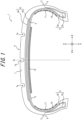
- FIG. 1 is a drawing illustrating a pneumatic tire 1 (hereinafter referred to simply as "tire 1") as an embodiment of a pneumatic tire of the present invention. More specifically, FIG. 1 is a tire widthwise cross sectional view of the tire 1.
- tire widthwise cross section refers to a cross section in a plane that is parallel to a tire central axis and contains the tire central axis.
- the tire 1 of this embodiment includes a pair of bead portions 2, sidewall portions 3 connected to the bead portions 2, and a tread portion 4 connected to the sidewall portions 3.
- the tire 1 also includes a carcass 5 that straddles between a pair of bead cores 2a embedded in the pair of bead portions 2.
- the tire 1 includes a belt 6 disposed outside a crown portion of the carcass 5 in a tire radial direction A.
- the tire also includes tread rubber 7 disposed outside the belt 6 in the tire radial direction A, and side rubber 8 disposed outside side portions of the carcass 5 in a tire width direction B.
- the tire 1 includes an inner liner 9 that is laminated on an inner surface of the carcass 5.
- each of the bead portions 2 of the tire 1 of this embodiment includes, in addition to the bead core 2a described above, a bead filler 2b disposed outside the bead core 2a in the tire radial direction A.
- the bead filler 2b of this embodiment is in the outer shape of an approximately triangle in the tire widthwise cross sectional view, but the cross sectional shape is not particularly limited.
- the configuration of the bead portions 2 of the tire 1 is not limited to the configuration illustrated in FIG. 1 . Therefore, the cross sectional shapes, sizes, and materials of the bead cores 2a and bead fillers 2b are also not particularly limited.
- the tire 1 may be configured without bead cores 2a and bead fillers 2b.
- the carcass 5 of this embodiment is constituted of a single carcass ply made of organic fibers, but the configuration of the carcass 5 is not particularly limited. Therefore, the number and material of carcass plies constituting the carcass 5 are not particularly limited.
- the belt 6 of this embodiment is constituted of two belt layers 6a and 6b, which are laminated in the tire radial direction A.
- Each of the belt layers 6a and 6b is made of a belt play in which belt cords, such as steel cords, are arranged inclinedly at an angle of 10° to 40° with respect to a tire circumferential direction C.
- the two belt plies are placed on top of each other with the directions of inclination of the belt cords different from each other. Therefore, the belt cords mutually cross each other between the belt plies, which increases belt rigidity and reinforces the almost entire width of the tread portion 4 by the hoop effect.
- the configuration of the belt 6 is not particularly limited. Therefore, the material of the belt cords in the belt 6, the number of hammerings, the inclination angle, the number of belt layers, and the like are not particularly limited.
- the tread rubber 7 configures an outer surface (hereinafter referred to as "tread outer surface") of the tread portion 4 in the tire radial direction A.
- tread outer surface In the tread outer surface, a tread pattern including circumferential grooves 7a extending in the tire circumferential direction C, not-illustrated widthwise grooves extending in the tire width direction B, and the like, is formed.
- the side rubber 8 configures outer surfaces of the sidewall portions 3 in the tire width direction B, and is formed integrally with the above-described tread rubber 7.
- the materials of the tread rubber 7 and the side rubber 8 are not particularly limited.
- the inner liner 9 is laminated on the inner surface of the carcass 5, and is made of, for example, butyl-type rubber, which has low air permeability.
- butyl-type rubber refers to butyl rubber and a derivative thereof, butyl halide rubber.
- the inner liner 9 may also be made of any known material, and the material thereof is not particularly limited.
- the tire 1 includes sound dampers 10 attached onto inner surfaces of the sidewall portions 3.
- the sound damper 10 may be attached onto the inner surface of only one of the sidewall portions 3, but is preferably attached onto the inner surface of each of the sidewall portions 3 on both sides as in this embodiment. Thereby, cavity resonance can be further restrained.
- the sound damper 10 is a porous material such as a sponge material, for example.
- the sound damper 10 of this embodiment has a flat outer shape in the tire widthwise cross sectional view illustrated in FIG. 1 , but the shape thereof is not particularly limited.
- the dimensions and the like of the sound damper 10 are not particularly limited, but the volume of the sound damper 10 is preferably 0.1% to 80% of the total volume of a cavity of the tire 1. Setting the volume of the sound damper 10 to 0.1% or more of the total volume of the cavity of the tire 1 can improve a sound damping property. On the other hand, setting the volume of the sound damper 10 to 80% or less of the total volume of the cavity of the tire 1 can restrain a weight increase caused by the sound damper 10.
- the "volume” here refers to the volume of the tire 1 removed from a rim under normal temperature and normal pressure.
- the “total volume of the cavity of the tire” refer to a total volume when the tire 1 is mounted on an applicable rim and filled with specified internal pressure.
- the sponge material may be a sponge-like porous structure and includes, for example, a so-called sponge with continuous bubbles made of foamed rubber or synthetic resin.
- the sponge material also includes a web-like material in which animal fibers, plant fibers, synthetic fibers, or the like are intertwined and connected together.
- the above-described "porous structure" is not limited to a structure with continuous bubbles, but also includes a structure with independent bubbles.
- pores formed in a surface or inside of the sponge material convert the vibrational energy of vibrating air into thermal energy. This restrains cavity resonance in the cavity of the tire, resulting in reduced road noise.
- the sponge material examples include, for example, synthetic resin sponge such as ether-based polyurethane sponge, ester-based polyurethane sponge, and polyethylene sponge, and rubber sponge (EPDM sponge) such as chloroprene rubber sponge (CR sponge), ethylene propylene diene rubber sponge (EPDM sponge), and nitrile rubber sponge (NBR sponge).
- synthetic resin sponge such as ether-based polyurethane sponge, ester-based polyurethane sponge, and polyethylene sponge
- EPDM sponge rubber sponge
- polyurethane sponge including ether-based polyurethane sponge, polyethylene sponge, or the like.
- the hardness of the sponge material is not particularly limited, but is preferably in a range of 5 to 450 N. Setting the hardness to 5 N or higher can improve the sound damping property, while setting the hardness to 450 N or lower can increase adhesive strength of the sponge material. It is more preferable that the hardness of the sponge material is set in a range of 8 to 300 N. Thereby, the above-described effects can be further improved.
- “hardness” refers to a value measured in conformity with Method A in Section 6.3 of the measurement methods in Section 6 of JIS K6400.
- the specific gravity of the sponge material is between 0.001 and 0.090. Setting the specific gravity of the sponge material to 0.001 or more can improve the sound damping property, while setting the specific gravity of the sponge material to 0.090 or less can restrain a weight increase caused by the sponge material. It is more preferable that the specific gravity of the sponge material is between 0.003 and 0.080. Thereby, the above-described effects can be further improved.
- “specific gravity” refers to a value that is measured in conformity with a method in Section 5 of JIS K6400, and is obtained by converting apparent density into specific gravity.
- the tensile strength of the sponge material is between 20 and 500 kPa. Setting the tensile strength to 20 kPa or higher can improve the adhesive strength, while setting the tensile strength to 500 kPa or lower can improve the productivity of the sponge material. It is more preferable that the tensile strength of the sponge material is between 40 and 400 kPa. Thereby, the above-described effects can be further improved.
- "tensile strength” refer to a value measured in conformity with a measurement method in Section 10 of JIS K6400 with a No. 1 dumbbell specimen.
- the breaking elongation of the sponge material is 110% or more and 800% or less. Setting the breaking elongation to 110% or more can prevent the sponge material from cracking, while the breaking elongation to 800% or less can improve the productivity of the sponge material. It is more preferable that the breaking elongation of the sponge material is between 130% and 750% inclusive. Thereby, the above-described effects can be further improved.
- breaking elongation refers to a value measured in conformity with a measurement method in Section 10 of JIS K6400 with a No. 1 dumbbell specimen.
- the tear strength of the sponge material is between 1 and 130 N/cm. Setting the tear strength to 1 N/cm or higher can prevent the sponge material from cracking, while setting the tear strength to 130 N/cm or less improves the manufacturability of the sponge material. It is more preferable that the tear strength of the sponge material is between 3 and 115 N/cm. Thereby, the above-described effects can be further improved.
- “tear strength” refers to a value measured in conformity with a measurement method in Section 11 of JIS K6400 with a No. 1 specimen.
- the foaming ratio of the sponge material is 1% or more and 40% or less. Setting the foaming ratio to 1% or more can improve the sound damping property, while setting the foaming ratio to 40% or less can improve the productivity of the sponge material. It is more preferable that the foaming ratio of the sponge material is between 2 and 25%. Thereby, the above-described effects can be further improved.
- the "foaming ratio" refers to a value in which 1 is subtracted from the ratio SG1/SG2 of the specific gravity SG1 of a solid phase of the sponge material to the specific gravity SG2 of the sponge material and then the result is multiplied by 100.
- the entire mass of the sponge material is between 5 and 800 g. Setting the mass to 5 g or more can improve the sound damping property, while setting the mass to 800 g or less can restrain a weight increase caused by the sponge material. It is more preferable that the mass of the sponge material is between 20 and 600 g. Thereby, the above-described effects can be further improved.
- the material that forms the sound damper 10 can be anything as long as the material can reduce the cavity resonance energy by mitigating or absorbing the cavity resonance energy, converting the cavity resonance energy into other energy (e.g., thermal energy), or the like, and is not limited to the porous material described above.
- a non-woven fabric made of organic or inorganic fibers may also be used.
- Examples of organic fibers used in the sound damper 10 include rayon, polyethylene terephthalate, polyethylene naphthalate, polybenzimidazole, polyphenylene sulfide, polyvinyl alcohol, aliphatic polyamide, aromatic polyamide (aramid), aromatic polyimide, and the like.
- Examples of inorganic fibers used in the sound damper 10 include carbon fibers, fluorine fibers, glass fibers, metal fibers, and the like. A mixture of two or more different types of fibers may also be used.
- the length and diameter of the fibers that form the non-woven fabric used in the sound damper 10 can be set arbitrarily. Although not specifically limited, the diameter of the fibers may be, for example, 100 nm to 200 ⁇ m.
- the basis weight of the non-woven fabric used in the sound damper 10 is between 10 g/m 2 and 300 g/m 2 . Setting the basis weight to 10 g/m 2 or more can made the fibers more uniform, while setting the basis weight to 300 g/m 2 prevents an excessive weight increase due to the provision of the sound damper 10.
- FIG. 2 is a tire circumferential cross sectional view of the tire 1.
- the term "tire circumferential cross section” refers to a cross sectional view of the tire 1 at a tire equatorial plane CL. Note that, FIG. 2 omits details of a cross section inside the tread portion 4 such as the belt 6.
- a plurality of through holes 11 penetrating in the tire width direction B are formed in the sound damper 10.
- the sound damper 10 can be deformed in the tire radial direction A by varying the lengths of the through holes 11 in the tire radial direction A so as to follow the deformation of the sidewall portion 3 in the tire radial direction A.
- the sound damper 10 with such through holes 11 can follow the bending deformation of the sidewall portion 3 more easily than tire radial direction a sound damper without through holes 11. Therefore, it is possible to realize the sound damper 10 that is difficult to be damaged by the repeated bending deformation occurring in the sidewall portion 3.
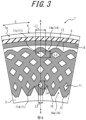
- FIG. 3 is an enlarged cross sectional view that illustrates a part of the tire circumferential cross section of the tire 1 illustrated in FIG. 2 in an enlarged manner.
- FIG. 3 illustrates a region indicated by the dashed line in FIG. 2 in an enlarged manner, but the same is true in another region in the tire circumferential direction C.
- the plurality of through holes 11 are formed at different positions in the tire circumferential direction C.
- the term "the through holes 11 are formed at different positions in the tire circumferential direction C" means that there are at least two through holes 11 that do not overlap in the tire radial direction A. This allows to restrain variations in the tire circumferential direction C in a following property, with which the sound damper 10 is deformed by following the deformation of the sidewall portion 3 in the tire radial direction A.
- the plurality of through holes 11 are arranged at predetermined intervals in the sound damper 10 attached onto the inner surface of the sidewall portion 3 in the entire tire circumferential direction C.
- the sound damper 10 is attached along the inner surface of the sidewall portion 3 in the entire tire circumferential direction C. This improves the sound damping property of the sound damper 10, as compared to a configuration in which the sound damper 10 is not attached in the entire tire circumferential direction C.
- the through holes 11 are formed at different positions in the tire radial direction A.
- the term "the through holes 11 are formed at the different positions in the tire radial direction A” means that there are at least two through holes 11 that do not overlap in the tire circumferential direction C. This allows to restrain variations in the tire radial direction A in the following property, with which the sound damper 10 is deformed by following the deformation of the sidewall portion 3 in the tire radial direction A.
- the plurality of through holes 11 are arranged at predetermined intervals in the sound damper 10 attached onto the inner surface of the sidewall portion 3 in the entire tire radial direction A.
- the tire widthwise cross sectional view of the tire 1 at any position in the hole formation region X includes at least one through hole 11. Due to this arrangement of the through holes 11, variations in the tire circumferential direction C in the following property, with which the sound damper 10 is deformed by following the deformation of the sidewall portion 3 in the tire radial direction A, can be further restrained.
- Such an arrangement of the through holes 11 does not have to be achieved by arranging the through holes 11 in a regular manner. However, it is preferable that the through holes 11 are arranged in a staggered manner as in this embodiment. Thereby, the above-described arrangement of the through holes 11 can be easily realized, as compared to a configuration in which the through holes are randomly arranged.
- the through holes 11 located outside in the tire radial direction A are longer in length in the tire circumferential direction C than the through holes 11 located inside in the tire radial direction A.
- length in the tire circumferential direction C is compared between a through hole 11c located outermost in the tire radial direction A and a through hole 11d located innermost in the tire radial direction A, at the same position in the tire circumferential direction C.
- the maximum length L1 of the through hole 11c in the tire circumferential direction C is longer than the maximum length L2 of the through hole 11d in the tire circumferential direction C.
- the through holes 11 located outside in the tire radial direction A are shorter in length in the tire radial direction A than the through holes 11 located inside in the tire radial direction A.
- length in the tire radial direction A is compared between the above-described two through holes 11c and 11d.
- the maximum length L3 of the through hole 11c in the tire radial direction A is shorter than the maximum length L4 of the through hole 11d in the tire radial direction A.
- the through hole 11c is more easily flattened in the tire radial direction A than the through hole 11d when the sidewall portion 3 is bent and deformed in the tire radial direction A.
- deformability in the tire radial direction A at the outside in the tire radial direction A is made higher than deformability in the tire radial direction A at the inside in the tire radial direction A.
- adjusting the lengths of the through holes 11 in the tire radial direction A and the tire circumferential direction C allows to adjust the deformation performance in the tire radial direction A depending on position in the tire radial direction A.
- the sound damper 10 is hard to deform in the tire radial direction A in the vicinity of the bead portion 2, which is secured to the rim so as not to be bent and deformed during tire rolling, that is, at a position of the sidewall portion 3 on the inside in the tire radial direction A.
- the sidewall portion 3 is reinforced by the sound damper 10, and the bending deformation in the tire radial direction A is restrained at the position of the sidewall portion 3 in the vicinity of the bead portion 2.
- the two through holes 11c and 11d described above are examples, and two through holes 11 between which the same relationship as "L1>L2 and L3 ⁇ L4" above is established are not limited to the through holes 11c and 11b. More specifically, in this embodiment, the same relationship as "L1>L2 and L3 ⁇ L4" above is established between any two through holes 11 at different positions in the tire radial direction A.
- the sound damper 10 of this embodiment is attached onto the inner surface of the sidewall portion 3 with an outer edge 12 at the outside in the tire radial direction A pulled in the tire circumferential direction C more than a natural state, and with an inner edge 13 at the inside in the tire radial direction A compressed in the tire circumferential direction C more than the natural state.
- the "natural state” refers to a state in which no external force other than gravity is applied in the atmosphere.
- an outer position in the tire radial direction A becomes "sparse”
- an inner position in the tire radial direction A becomes "dense".
- the deformability of the sound damper 10 in the tire radial direction A can be increased at the outer position of the sidewall portion 3 in the tire radial direction A, which is easily bent and deformed during tire rolling.
- the sidewall portion 3 is reinforced by the sound damper 10, and the bending deformation in the tire radial direction A is restrained.
- the tire 1 satisfies both of the above-described "sparse-dense" relationship and the above-described length relationship of "L1>L2 and L3 ⁇ L4". Thereby, the above effects can be further improved.
- FIG. 4 is a schematic diagram illustrating an example of the attachment method of the sound damper 10 of this embodiment.
- the sound damper 10 is configured into a linearly extending strip in a natural state before being attached onto the inner surface of the sidewall portion 3.
- the strip configuring the sound damper 10 is attached onto the inner surface of the sidewall portion 3 along the tire circumferential direction C.
- the strip configuring the sound damper 10 is attached onto the inner surface of the sidewall portion 3 using, for example, an adhesive material such as double-sided adhesive tape or glue, while curving both end faces in a strip width direction into an arc shape so as to follow the tire circumferential direction C (refer to the arrow in FIG. 4 ).
- an adhesive material such as double-sided adhesive tape or glue
- the strip configuring the sound damper 10 can be attached onto the inner surface of the sidewall portion 3 with the outer edge 12 at the outside in the tire radial direction A pulled in the tire circumferential direction C more than the natural state, and with the inner edge 13 at the inside in the tire radial direction A compressed in the tire circumferential direction C more than the natural state.
- the through holes 11 of the sound damper 10 of this embodiment each have an approximately diamond shape in the tire circumferential cross sectional view illustrated in FIGS. 2 and 3 , but this shape is not particularly limited.
- the through holes 11 of the sound damper 10 may each be in the shape of a polygon other than a diamond, a circle, an oval, or the like.
- a plurality of recesses 14 are formed at intervals in the tire circumferential direction C.
- the formation of such recesses 14 makes it easy to deform the sound damper 10 along the tire circumferential direction C on the inner surface of the sidewall portion 3. More specifically, the presence of the recesses 14 makes it easier for the outer edge 12 to be extensionally deformed in the tire circumferential direction C, and for the inner edge 13 to be compressively deformed in the tire circumferential direction C. Therefore, even when the attachment method as illustrated in FIG. 4 is adopted, for example, the sound damper 10 can be easily attached onto the inner surface of the sidewall portion 3 along the tire circumferential direction C.
- the recesses 14 are not limited to V-shaped notches 14a as illustrated in this embodiment.
- the recesses 14 may be notches of another shape, such as U-shaped notches, or linear slits as illustrated in FIG. 5 .
- the slits as the recesses 14 will be described later (refer to FIG. 5 ).
- a sealant layer 15 is laminated on an inner surface of the tread portion 4.
- the plurality of through holes 11 are formed in the sound damper 10. Accordingly, the sound damper 10 is hard to damage even when the sound damper 10 is attached onto the inner surface of the sidewall portion 3, which improves durability.
- the sound damper 10 need not be attached on the inner surface of the tread portion 4. Therefore, the sealant layer 15 may be provided on the inner surface of the tread portion 4, as in the tire 1 of this embodiment. Thereby, the arrangement positions of the sound damper 10 and the sealant layer 15 can be different on an inner surface of the tire, so the sealant layer 15 is hard to adhere to the sound damper 10.
- the sealant layer 15 is laminated only on the inner surface of the tread portion 4 in the tire width direction B.
- the sound damper 10 of this embodiment is attached only onto the inner surface of the sidewall portion 3, but is not limited to this configuration.
- the sound damper 10 may extend to the inner surface of the tread portion 4, in addition to the inner surface of the sidewall portion 3, as long as the sound damper 10 does not overlap the sealant layer 15 in the tire width direction B.
- a sealant liquid which is an adhesive fluid
- a sealant agent conventionally known as a puncture sealant
- a sealant agent for example, a silicone compound, a styrene compound, a urethane compound, an ethylene compound, a gel sheet consisting mainly of polybutene and terpene resin, or the like can be used.
- FIG. 5 is a drawing illustrating a tire 21 including a sound damper 30 as a variation of the sound damper illustrated in FIGS. 1 to 4 and not according to the present invention.
- the tire 21 differs only in the configuration of the sound damper, while the other configurations are common.
- FIG. 5 is an enlarged cross sectional view of the sound damper 30 illustrating the same position as the sound damper 10 in FIG. 3 .
- the sound damper 30 differs from the above-described sound damper 10 (refer to FIG. 3 and the like) in the shapes of through holes and recesses.
- Through holes 31 of the sound damper 30 illustrated in FIG. 5 are constituted of slits extending in the tire radial direction A.
- the through holes 31 may be such slits.
- the recesses 34 of the sound damper 30 illustrated in FIG. 5 are constituted of slits 34a extending in the tire radial direction A.
- the recesses 34 may be such slits 34a.
- both of the through holes 31 and the recesses 34 of the sound damper 30 into a slit shape makes it easier to follow the bending of the sidewall portion 3, as in the sound damper 10 illustrated in FIGS. 1 to 4 , as compared to the configuration without the through holes 31 and recesses 34. Furthermore, it is easier for the sound damper 30 illustrated in FIG. 5 to secure volume than for the sound damper 10 illustrated in FIGS. 1 to 4 . Therefore, the sound damping property can be further improved.
- the present invention relates to a pneumatic tire.
Landscapes
- Engineering & Computer Science (AREA)
- Mechanical Engineering (AREA)
- Tires In General (AREA)
Description
- The present invention relates to a pneumatic tire.
- To reduce the resonant vibration (cavity resonance) of air or gas generated in cavities of tires, it is known to dispose sound dampers made of sponge materials on inner surfaces of tires. Patent Literature (PTL) 1 describes this type of sound damper. The sound damper can convert the vibration energy of air or gas in a cavity of a tire into thermal energy, thereby restraining cavity resonance in the cavity of the tire. Patent Literature (PTL) 2 also describes the use of non-woven fabric as a sound damper.
-
JP2007302072 -
JP2008080969 -
- PTL 1:
JP 2005-254924 - PTL 2:
JP 2016-210250 - The sound damper described in either
PTL 1 orPTL 2 is attached onto an inner surface of a tread portion. From the viewpoint of restraining cavity resonance in a cavity of a tire, it is preferable that the sound damper is attached not only onto the inner surface of the tread portion but also onto inner surfaces of sidewall portions. However, in a case in which the sound damper described inPTL 1 orPTL 2 is attached onto each of the inner surfaces of the sidewall portions, the sound damper cannot fully follow repeated bending deformation occurring in the sidewall portion, which results in damage and deterioration of the sound damper. - It would be helpful to provide a pneumatic tire including a sound damper having a shape that easily follows the bending deformation of a sidewall portion.
- According to a first aspect of the invention there is provided a pneumatic tire as specified in
claim 1. - According to the invention, it is possible to provide the pneumatic tire including the sound damper having the shape that easily follows the bending deformation of the sidewall portion.
- In the accompanying drawings:
-
FIG. 1 is a tire widthwise cross sectional view of a pneumatic tire as an embodiment of the present invention; -
FIG. 2 is a tire circumferential cross sectional view of the pneumatic tire illustrated inFIG. 1 ; -
FIG. 3 is an enlarged cross sectional view that illustrates a part of a tire circumferential cross section of the tire illustrated inFIG. 2 in an enlarged manner; -
FIG. 4 is a schematic diagram illustrating an example of an attachment method of a sound damper illustrated inFIG. 1 ; and -
FIG. 5 is an enlarged cross sectional view that illustrates a part of a tire circumferential cross section of a pneumatic tire including a sound damper, not according to the present invention, as a variation of the sound damper illustrated inFIG. 1 . - An embodiment of a pneumatic tire according to the present invention will be exemplarily described below with reference to the drawings. In the drawings, common members and components are indicated with the same reference numerals.
-
FIG. 1 is a drawing illustrating a pneumatic tire 1 (hereinafter referred to simply as "tire 1") as an embodiment of a pneumatic tire of the present invention. More specifically,FIG. 1 is a tire widthwise cross sectional view of thetire 1. The term "tire widthwise cross section" refers to a cross section in a plane that is parallel to a tire central axis and contains the tire central axis. - As illustrated in
FIG. 1 , thetire 1 of this embodiment includes a pair ofbead portions 2,sidewall portions 3 connected to thebead portions 2, and atread portion 4 connected to thesidewall portions 3. Thetire 1 also includes acarcass 5 that straddles between a pair ofbead cores 2a embedded in the pair ofbead portions 2. Thetire 1 includes a belt 6 disposed outside a crown portion of thecarcass 5 in a tire radial direction A. The tire also includes tread rubber 7 disposed outside the belt 6 in the tire radial direction A, andside rubber 8 disposed outside side portions of thecarcass 5 in a tire width direction B. Furthermore, thetire 1 includes aninner liner 9 that is laminated on an inner surface of thecarcass 5. - As illustrated in
FIG. 1 , each of thebead portions 2 of thetire 1 of this embodiment includes, in addition to thebead core 2a described above, abead filler 2b disposed outside thebead core 2a in the tire radial direction A. Thebead filler 2b of this embodiment is in the outer shape of an approximately triangle in the tire widthwise cross sectional view, but the cross sectional shape is not particularly limited. Furthermore, the configuration of thebead portions 2 of thetire 1 is not limited to the configuration illustrated inFIG. 1 . Therefore, the cross sectional shapes, sizes, and materials of thebead cores 2a andbead fillers 2b are also not particularly limited. Furthermore, thetire 1 may be configured withoutbead cores 2a andbead fillers 2b. - The
carcass 5 of this embodiment is constituted of a single carcass ply made of organic fibers, but the configuration of thecarcass 5 is not particularly limited. Therefore, the number and material of carcass plies constituting thecarcass 5 are not particularly limited. - The belt 6 of this embodiment is constituted of two
belt layers belt layers tread portion 4 by the hoop effect. However, the configuration of the belt 6 is not particularly limited. Therefore, the material of the belt cords in the belt 6, the number of hammerings, the inclination angle, the number of belt layers, and the like are not particularly limited. - The tread rubber 7 configures an outer surface (hereinafter referred to as "tread outer surface") of the
tread portion 4 in the tire radial direction A. In the tread outer surface, a tread pattern includingcircumferential grooves 7a extending in the tire circumferential direction C, not-illustrated widthwise grooves extending in the tire width direction B, and the like, is formed. Theside rubber 8 configures outer surfaces of thesidewall portions 3 in the tire width direction B, and is formed integrally with the above-described tread rubber 7. The materials of the tread rubber 7 and theside rubber 8 are not particularly limited. - The
inner liner 9 is laminated on the inner surface of thecarcass 5, and is made of, for example, butyl-type rubber, which has low air permeability. The term "butyl-type rubber" refers to butyl rubber and a derivative thereof, butyl halide rubber. However, theinner liner 9 may also be made of any known material, and the material thereof is not particularly limited. - As illustrated in
FIG. 1 , thetire 1 includessound dampers 10 attached onto inner surfaces of thesidewall portions 3. As illustrated inFIG. 1 , thesound damper 10 may be attached onto the inner surface of only one of thesidewall portions 3, but is preferably attached onto the inner surface of each of thesidewall portions 3 on both sides as in this embodiment. Thereby, cavity resonance can be further restrained. - The
sound damper 10 is a porous material such as a sponge material, for example. Thesound damper 10 of this embodiment has a flat outer shape in the tire widthwise cross sectional view illustrated inFIG. 1 , but the shape thereof is not particularly limited. The dimensions and the like of thesound damper 10 are not particularly limited, but the volume of thesound damper 10 is preferably 0.1% to 80% of the total volume of a cavity of thetire 1. Setting the volume of thesound damper 10 to 0.1% or more of the total volume of the cavity of thetire 1 can improve a sound damping property. On the other hand, setting the volume of thesound damper 10 to 80% or less of the total volume of the cavity of thetire 1 can restrain a weight increase caused by thesound damper 10. The "volume" here refers to the volume of thetire 1 removed from a rim under normal temperature and normal pressure. The "total volume of the cavity of the tire" refer to a total volume when thetire 1 is mounted on an applicable rim and filled with specified internal pressure. - When the
sound damper 10 is a sponge material, the sponge material may be a sponge-like porous structure and includes, for example, a so-called sponge with continuous bubbles made of foamed rubber or synthetic resin. In addition to the above-described sponge, the sponge material also includes a web-like material in which animal fibers, plant fibers, synthetic fibers, or the like are intertwined and connected together. The above-described "porous structure" is not limited to a structure with continuous bubbles, but also includes a structure with independent bubbles. In the sponge material as described above, pores formed in a surface or inside of the sponge material convert the vibrational energy of vibrating air into thermal energy. This restrains cavity resonance in the cavity of the tire, resulting in reduced road noise. - Examples of the sponge material include, for example, synthetic resin sponge such as ether-based polyurethane sponge, ester-based polyurethane sponge, and polyethylene sponge, and rubber sponge (EPDM sponge) such as chloroprene rubber sponge (CR sponge), ethylene propylene diene rubber sponge (EPDM sponge), and nitrile rubber sponge (NBR sponge). In terms of the sound damping property, light weight, adjustability in foaming, durability, and the like, it is preferable to use polyurethane sponge including ether-based polyurethane sponge, polyethylene sponge, or the like.
- In a case in which the
sound damper 10 is a sponge material, as in this embodiment, the hardness of the sponge material is not particularly limited, but is preferably in a range of 5 to 450 N. Setting the hardness to 5 N or higher can improve the sound damping property, while setting the hardness to 450 N or lower can increase adhesive strength of the sponge material. It is more preferable that the hardness of the sponge material is set in a range of 8 to 300 N. Thereby, the above-described effects can be further improved. Here, "hardness" refers to a value measured in conformity with Method A in Section 6.3 of the measurement methods in Section 6 of JIS K6400. - It is preferable that the specific gravity of the sponge material is between 0.001 and 0.090. Setting the specific gravity of the sponge material to 0.001 or more can improve the sound damping property, while setting the specific gravity of the sponge material to 0.090 or less can restrain a weight increase caused by the sponge material. It is more preferable that the specific gravity of the sponge material is between 0.003 and 0.080. Thereby, the above-described effects can be further improved. Here, "specific gravity" refers to a value that is measured in conformity with a method in
Section 5 of JIS K6400, and is obtained by converting apparent density into specific gravity. - It is preferable that the tensile strength of the sponge material is between 20 and 500 kPa. Setting the tensile strength to 20 kPa or higher can improve the adhesive strength, while setting the tensile strength to 500 kPa or lower can improve the productivity of the sponge material. It is more preferable that the tensile strength of the sponge material is between 40 and 400 kPa. Thereby, the above-described effects can be further improved. Here, "tensile strength" refer to a value measured in conformity with a measurement method in
Section 10 of JIS K6400 with a No. 1 dumbbell specimen. - It is preferable that the breaking elongation of the sponge material is 110% or more and 800% or less. Setting the breaking elongation to 110% or more can prevent the sponge material from cracking, while the breaking elongation to 800% or less can improve the productivity of the sponge material. It is more preferable that the breaking elongation of the sponge material is between 130% and 750% inclusive. Thereby, the above-described effects can be further improved. Here, "breaking elongation" refers to a value measured in conformity with a measurement method in
Section 10 of JIS K6400 with a No. 1 dumbbell specimen. - It is preferable that the tear strength of the sponge material is between 1 and 130 N/cm. Setting the tear strength to 1 N/cm or higher can prevent the sponge material from cracking, while setting the tear strength to 130 N/cm or less improves the manufacturability of the sponge material. It is more preferable that the tear strength of the sponge material is between 3 and 115 N/cm. Thereby, the above-described effects can be further improved. Here, "tear strength" refers to a value measured in conformity with a measurement method in
Section 11 of JIS K6400 with a No. 1 specimen. - It is preferable that the foaming ratio of the sponge material is 1% or more and 40% or less. Setting the foaming ratio to 1% or more can improve the sound damping property, while setting the foaming ratio to 40% or less can improve the productivity of the sponge material. It is more preferable that the foaming ratio of the sponge material is between 2 and 25%. Thereby, the above-described effects can be further improved. Here, the "foaming ratio" refers to a value in which 1 is subtracted from the ratio SG1/SG2 of the specific gravity SG1 of a solid phase of the sponge material to the specific gravity SG2 of the sponge material and then the result is multiplied by 100.
- It is preferable that the entire mass of the sponge material is between 5 and 800 g. Setting the mass to 5 g or more can improve the sound damping property, while setting the mass to 800 g or less can restrain a weight increase caused by the sponge material. It is more preferable that the mass of the sponge material is between 20 and 600 g. Thereby, the above-described effects can be further improved.
- The material that forms the
sound damper 10 can be anything as long as the material can reduce the cavity resonance energy by mitigating or absorbing the cavity resonance energy, converting the cavity resonance energy into other energy (e.g., thermal energy), or the like, and is not limited to the porous material described above. For example, a non-woven fabric made of organic or inorganic fibers may also be used. - Examples of organic fibers used in the
sound damper 10 include rayon, polyethylene terephthalate, polyethylene naphthalate, polybenzimidazole, polyphenylene sulfide, polyvinyl alcohol, aliphatic polyamide, aromatic polyamide (aramid), aromatic polyimide, and the like. Examples of inorganic fibers used in thesound damper 10 include carbon fibers, fluorine fibers, glass fibers, metal fibers, and the like. A mixture of two or more different types of fibers may also be used. - The length and diameter of the fibers that form the non-woven fabric used in the
sound damper 10 can be set arbitrarily. Although not specifically limited, the diameter of the fibers may be, for example, 100 nm to 200 µm. - It is preferable that the basis weight of the non-woven fabric used in the
sound damper 10 is between 10 g/m2 and 300 g/m2. Setting the basis weight to 10 g/m2 or more can made the fibers more uniform, while setting the basis weight to 300 g/m2 prevents an excessive weight increase due to the provision of thesound damper 10. -
FIG. 2 is a tire circumferential cross sectional view of thetire 1. The term "tire circumferential cross section" refers to a cross sectional view of thetire 1 at a tire equatorial plane CL. Note that,FIG. 2 omits details of a cross section inside thetread portion 4 such as the belt 6. As illustrated inFIGS. 1 and2 , a plurality of throughholes 11 penetrating in the tire width direction B are formed in thesound damper 10. Thesound damper 10 can be deformed in the tire radial direction A by varying the lengths of the throughholes 11 in the tire radial direction A so as to follow the deformation of thesidewall portion 3 in the tire radial direction A. Thesound damper 10 with such throughholes 11 can follow the bending deformation of thesidewall portion 3 more easily than tire radial direction a sound damper without throughholes 11. Therefore, it is possible to realize thesound damper 10 that is difficult to be damaged by the repeated bending deformation occurring in thesidewall portion 3. -
FIG. 3 is an enlarged cross sectional view that illustrates a part of the tire circumferential cross section of thetire 1 illustrated inFIG. 2 in an enlarged manner.FIG. 3 illustrates a region indicated by the dashed line inFIG. 2 in an enlarged manner, but the same is true in another region in the tire circumferential direction C. - As illustrated in
FIGS. 2 and3 , the plurality of throughholes 11 are formed at different positions in the tire circumferential direction C. The term "the throughholes 11 are formed at different positions in the tire circumferential direction C" means that there are at least two throughholes 11 that do not overlap in the tire radial direction A. This allows to restrain variations in the tire circumferential direction C in a following property, with which thesound damper 10 is deformed by following the deformation of thesidewall portion 3 in the tire radial direction A. In other words, it is more preferable that the plurality of throughholes 11 are arranged at predetermined intervals in thesound damper 10 attached onto the inner surface of thesidewall portion 3 in the entire tire circumferential direction C. - As illustrated in
FIGS. 2 and3 , it is preferable that thesound damper 10 is attached along the inner surface of thesidewall portion 3 in the entire tire circumferential direction C. This improves the sound damping property of thesound damper 10, as compared to a configuration in which thesound damper 10 is not attached in the entire tire circumferential direction C. - As illustrated in
FIGS. 2 and3 , the throughholes 11 are formed at different positions in the tire radial direction A. The term "the throughholes 11 are formed at the different positions in the tire radial direction A" means that there are at least two throughholes 11 that do not overlap in the tire circumferential direction C. This allows to restrain variations in the tire radial direction A in the following property, with which thesound damper 10 is deformed by following the deformation of thesidewall portion 3 in the tire radial direction A. In other words, it is preferable that the plurality of throughholes 11 are arranged at predetermined intervals in thesound damper 10 attached onto the inner surface of thesidewall portion 3 in the entire tire radial direction A. - Furthermore, in the
tire 1 of this embodiment, at least one throughhole 11 is provided in the tire widthwise cross sectional view (refer toFIG. 1 ) at any position in a region (hereinafter referred to as "hole formation region X") in the tire circumferential direction C between two throughholes sound damper 10 in tire circumferential direction C. More specifically, as illustrated inFIG. 1 , the tire widthwise cross sectional view of thetire 1 at any position in the hole formation region X includes at least one throughhole 11. Due to this arrangement of the throughholes 11, variations in the tire circumferential direction C in the following property, with which thesound damper 10 is deformed by following the deformation of thesidewall portion 3 in the tire radial direction A, can be further restrained. Such an arrangement of the throughholes 11 does not have to be achieved by arranging the throughholes 11 in a regular manner. However, it is preferable that the throughholes 11 are arranged in a staggered manner as in this embodiment. Thereby, the above-described arrangement of the throughholes 11 can be easily realized, as compared to a configuration in which the through holes are randomly arranged. - In addition, as illustrated in
FIG. 3 , of the throughholes 11, the throughholes 11 located outside in the tire radial direction A are longer in length in the tire circumferential direction C than the throughholes 11 located inside in the tire radial direction A. InFIG. 3 , by way of example, length in the tire circumferential direction C is compared between a throughhole 11c located outermost in the tire radial direction A and a throughhole 11d located innermost in the tire radial direction A, at the same position in the tire circumferential direction C. The maximum length L1 of the throughhole 11c in the tire circumferential direction C is longer than the maximum length L2 of the throughhole 11d in the tire circumferential direction C. - Furthermore, as illustrated in
FIG. 3 , of the throughholes 11, the throughholes 11 located outside in the tire radial direction A are shorter in length in the tire radial direction A than the throughholes 11 located inside in the tire radial direction A. InFIG. 3 , by way of example, length in the tire radial direction A is compared between the above-described two throughholes hole 11c in the tire radial direction A is shorter than the maximum length L4 of the throughhole 11d in the tire radial direction A. - Thus, by setting L1>L2 and L3<L4 for the through
holes hole 11c is more easily flattened in the tire radial direction A than the throughhole 11d when thesidewall portion 3 is bent and deformed in the tire radial direction A. This means that, in thesound damper 10, deformability in the tire radial direction A at the outside in the tire radial direction A is made higher than deformability in the tire radial direction A at the inside in the tire radial direction A. As described above, while arranging the plurality of throughholes 11 in the tire radial direction A allows to restrain large variations in deformation performance in the tire radial direction A depending on position in the tire radial direction A, adjusting the lengths of the throughholes 11 in the tire radial direction A and the tire circumferential direction C allows to adjust the deformation performance in the tire radial direction A depending on position in the tire radial direction A. In particular, it is preferable to set L1>L2 and L3<L4, as in thesound damper 10 of this embodiment. Thereby, the deformability of thesound damper 10 in the tire radial direction A can be improved at a position of thesidewall portion 3 on the outside in the tire radial direction A, which is easily deformed during tire rolling. In contrast, thesound damper 10 is hard to deform in the tire radial direction A in the vicinity of thebead portion 2, which is secured to the rim so as not to be bent and deformed during tire rolling, that is, at a position of thesidewall portion 3 on the inside in the tire radial direction A. As a result, thesidewall portion 3 is reinforced by thesound damper 10, and the bending deformation in the tire radial direction A is restrained at the position of thesidewall portion 3 in the vicinity of thebead portion 2. - Note that, the two through
holes holes 11 between which the same relationship as "L1>L2 and L3<L4" above is established are not limited to the throughholes holes 11 at different positions in the tire radial direction A. - Furthermore, the
sound damper 10 of this embodiment is attached onto the inner surface of thesidewall portion 3 with anouter edge 12 at the outside in the tire radial direction A pulled in the tire circumferential direction C more than a natural state, and with aninner edge 13 at the inside in the tire radial direction A compressed in the tire circumferential direction C more than the natural state. The "natural state" refers to a state in which no external force other than gravity is applied in the atmosphere. In other words, in thesound damper 10 of this embodiment, an outer position in the tire radial direction A becomes "sparse", and an inner position in the tire radial direction A becomes "dense". Thereby, the deformability of thesound damper 10 in the tire radial direction A can be increased at the outer position of thesidewall portion 3 in the tire radial direction A, which is easily bent and deformed during tire rolling. On the other hand, in the vicinity of thebead portion 2, i.e., at the inner position of thesidewall portion 3 in the tire radial direction A, which is secured to the rim so as not to be bent and deformed during tire rolling, thesidewall portion 3 is reinforced by thesound damper 10, and the bending deformation in the tire radial direction A is restrained. As in this embodiment, it is preferable that thetire 1 satisfies both of the above-described "sparse-dense" relationship and the above-described length relationship of "L1>L2 and L3<L4". Thereby, the above effects can be further improved. - The above-described length relationship of "L1>L2 and L3<L4" and the above-described "sparse-dense" relationship can be realized, for example, by an attachment method of the
sound damper 10 illustrated inFIG. 4. FIG. 4 is a schematic diagram illustrating an example of the attachment method of thesound damper 10 of this embodiment. As illustrated inFIG. 4 , thesound damper 10 is configured into a linearly extending strip in a natural state before being attached onto the inner surface of thesidewall portion 3. As illustrated inFIG. 4 , the strip configuring thesound damper 10 is attached onto the inner surface of thesidewall portion 3 along the tire circumferential direction C. More specifically, the strip configuring thesound damper 10 is attached onto the inner surface of thesidewall portion 3 using, for example, an adhesive material such as double-sided adhesive tape or glue, while curving both end faces in a strip width direction into an arc shape so as to follow the tire circumferential direction C (refer to the arrow inFIG. 4 ). In this way, the strip configuring thesound damper 10 can be attached onto the inner surface of thesidewall portion 3 with theouter edge 12 at the outside in the tire radial direction A pulled in the tire circumferential direction C more than the natural state, and with theinner edge 13 at the inside in the tire radial direction A compressed in the tire circumferential direction C more than the natural state. In other words, the "sparse-dense" relationship described above can be realized. In a case in which original holes, which are bases of the throughholes 11, are formed in the same shape and with the same area regardless of position in the tire radial direction A, adopting the attachment method illustrated inFIG. 4 ensures that theouter edge 12 is pulled in the tire circumferential direction C and theinner edge 13 is compressed in the tire circumferential direction C. In other words, by attaching such a strip to the inner surface of thesidewall portion 3 using the attachment method illustrated inFIG. 4 , the above-described length relationship of "L1>L2 and L3<L4" can be achieved. - The through holes 11 of the
sound damper 10 of this embodiment each have an approximately diamond shape in the tire circumferential cross sectional view illustrated inFIGS. 2 and3 , but this shape is not particularly limited. For example, the throughholes 11 of thesound damper 10 may each be in the shape of a polygon other than a diamond, a circle, an oval, or the like. - Furthermore, as illustrated in
FIG. 3 , in theouter edge 12 and theinner edge 13 of thesound damper 10 of this embodiment, a plurality ofrecesses 14 are formed at intervals in the tire circumferential direction C. The formation ofsuch recesses 14 makes it easy to deform thesound damper 10 along the tire circumferential direction C on the inner surface of thesidewall portion 3. More specifically, the presence of therecesses 14 makes it easier for theouter edge 12 to be extensionally deformed in the tire circumferential direction C, and for theinner edge 13 to be compressively deformed in the tire circumferential direction C. Therefore, even when the attachment method as illustrated inFIG. 4 is adopted, for example, thesound damper 10 can be easily attached onto the inner surface of thesidewall portion 3 along the tire circumferential direction C. Note that, therecesses 14 are not limited to V-shapednotches 14a as illustrated in this embodiment. For example, therecesses 14 may be notches of another shape, such as U-shaped notches, or linear slits as illustrated inFIG. 5 . The slits as therecesses 14 will be described later (refer toFIG. 5 ). - As illustrated in
FIG. 1 , in thetire 1, asealant layer 15 is laminated on an inner surface of thetread portion 4. As described above, the plurality of throughholes 11 are formed in thesound damper 10. Accordingly, thesound damper 10 is hard to damage even when thesound damper 10 is attached onto the inner surface of thesidewall portion 3, which improves durability. In other words, thesound damper 10 need not be attached on the inner surface of thetread portion 4. Therefore, thesealant layer 15 may be provided on the inner surface of thetread portion 4, as in thetire 1 of this embodiment. Thereby, the arrangement positions of thesound damper 10 and thesealant layer 15 can be different on an inner surface of the tire, so thesealant layer 15 is hard to adhere to thesound damper 10. This makes it difficult to deteriorate the adhesive performance of thesealant layer 15, thereby increasing the durability of sealing performance by thesealant layer 15. Thesealant layer 15 is laminated only on the inner surface of thetread portion 4 in the tire width direction B. Note that, thesound damper 10 of this embodiment is attached only onto the inner surface of thesidewall portion 3, but is not limited to this configuration. Thesound damper 10 may extend to the inner surface of thetread portion 4, in addition to the inner surface of thesidewall portion 3, as long as thesound damper 10 does not overlap thesealant layer 15 in the tire width direction B. - A sealant liquid, which is an adhesive fluid, can be used for the
sealant layer 15. For example, a sealant agent conventionally known as a puncture sealant can be used. As the sealant agent, for example, a silicone compound, a styrene compound, a urethane compound, an ethylene compound, a gel sheet consisting mainly of polybutene and terpene resin, or the like can be used. -
FIG. 5 is a drawing illustrating atire 21 including asound damper 30 as a variation of the sound damper illustrated inFIGS. 1 to 4 and not according to the present invention. Compared to thetire 1 described above, thetire 21 differs only in the configuration of the sound damper, while the other configurations are common. Thus, only the difference of thesound damper 30 from the above-described sound damper 10 (refer toFIG. 3 and the like) will be described here.FIG. 5 is an enlarged cross sectional view of thesound damper 30 illustrating the same position as thesound damper 10 inFIG. 3 . - As illustrated in
FIG. 5 , thesound damper 30 differs from the above-described sound damper 10 (refer toFIG. 3 and the like) in the shapes of through holes and recesses. Throughholes 31 of thesound damper 30 illustrated inFIG. 5 are constituted of slits extending in the tire radial direction A. The through holes 31 may be such slits. - The
recesses 34 of thesound damper 30 illustrated inFIG. 5 are constituted ofslits 34a extending in the tire radial direction A. Therecesses 34 may besuch slits 34a. - Forming both of the through
holes 31 and therecesses 34 of thesound damper 30 into a slit shape makes it easier to follow the bending of thesidewall portion 3, as in thesound damper 10 illustrated inFIGS. 1 to 4 , as compared to the configuration without the throughholes 31 and recesses 34. Furthermore, it is easier for thesound damper 30 illustrated inFIG. 5 to secure volume than for thesound damper 10 illustrated inFIGS. 1 to 4 . Therefore, the sound damping property can be further improved. - The present invention relates to a pneumatic tire.
-
- 1, 21
- Tire
- 2
- Bead portion
- 2a
- Bead core
- 2b
- Bead filler
- 3
- Sidewall portion
- 4
- Tread portion
- 5
- Carcass
- 6
- Belt
- 6a, 6b
- Belt layer
- 7
- Tread rubber
- 7a
- Circumferential groove
- 8
- Side rubber
- 9
- Inner liner
- 10, 30
- Sound damper
- 11, 11a, 11b, 11c, 11d, 31
- Through hole
- 12
- Outer edge
- 13
- Inner edge
- 14, 34
- Recess
- 14a
- Notch
- 15
- Sealant layer
- 34a
- Slit
- A
- Tire radial direction
- B
- Tire width direction
- C
- Tire circumferential direction
- CL
- Tire equatorial plane
- L1, L2
- Maximum length of through hole in tire circumferential direction
- L3, L4
- Maximum length of through hole in tire radial direction
- X
- Hole formation region
Claims (6)
- A pneumatic tire (1) comprising a sound damper (10) attached onto an inner surface of a sidewall portion (3), whereinthe sound damper is formed with a plurality of through holes (11) penetrating in a tire width direction (B), andthe sound damper is deformable in a tire radial direction (A) by varying lengths of the through holes in the tire radial direction by following deformation of the sidewall portion in the tire radial direction;wherein the plurality of through holes are formed at different positions in a tire circumferential direction (C);wherein the plurality of through holes are formed at different positions in the tire radial direction; andwherein, of the through holes, one or more through holes (11c) located outside in the tire radial direction are longer in length (L1) in the tire circumferential direction than one or more through holes (11d) located inside in the tire radial direction, and, of the through holes, one or more through holes located outside in the tire radial direction are shorter in length (L3) in the tire radial direction than one or more through holes located inside in the tire radial direction.
- The pneumatic tire (1) according to claim 1, wherein at least one of the through holes (11) is provided in a tire widthwise cross sectional view at any position in a tire circumferential region between two through holes at both ends of the sound damper (10) in the tire circumferential direction.
- The pneumatic tire (1) according to claim 2, wherein the through holes (11) are arranged in a staggered manner.
- The pneumatic tire (1) according to any preceding claim, wherein the sound damper (10) is attached onto the inner surface of the sidewall portion (3) with an outer edge (12) at outside in the tire radial direction (A) pulled in the tire circumferential direction (C) more than a natural state, and with an inner edge (13) at inside in the tire radial direction compressed in the tire circumferential direction more than the natural state.
- The pneumatic tire (1) according to claim 4, wherein in the outer edge (12) and the inner edge (13) of the sound damper (10), a plurality of recesses (14) are formed at intervals in the tire circumferential direction (C).
- The pneumatic tire (1) according to any preceding claim, wherein a sealant layer (15) is laminated on an inner surface of a tread portion (4).
Applications Claiming Priority (2)
| Application Number | Priority Date | Filing Date | Title |
|---|---|---|---|
| JP2019223173A JP7352458B2 (en) | 2019-12-10 | 2019-12-10 | pneumatic tires |
| PCT/JP2020/023658 WO2021117271A1 (en) | 2019-12-10 | 2020-06-16 | Pneumatic tire |
Publications (3)
| Publication Number | Publication Date |
|---|---|
| EP4074525A1 EP4074525A1 (en) | 2022-10-19 |
| EP4074525A4 EP4074525A4 (en) | 2023-04-19 |
| EP4074525B1 true EP4074525B1 (en) | 2024-12-04 |
Family
ID=76311567
Family Applications (1)
| Application Number | Title | Priority Date | Filing Date |
|---|---|---|---|
| EP20900095.9A Active EP4074525B1 (en) | 2019-12-10 | 2020-06-16 | Pneumatic tire |
Country Status (3)
| Country | Link |
|---|---|
| EP (1) | EP4074525B1 (en) |
| JP (1) | JP7352458B2 (en) |
| WO (1) | WO2021117271A1 (en) |
Family Cites Families (9)
| Publication number | Priority date | Publication date | Assignee | Title |
|---|---|---|---|---|
| US4664168A (en) * | 1985-01-22 | 1987-05-12 | The Uniroyal Goodrich Tire Company | Self-sealing tire with edge strips for tire sealant |
| JP4984633B2 (en) | 2006-05-10 | 2012-07-25 | 横浜ゴム株式会社 | Pneumatic tire |
| JP2008080969A (en) | 2006-09-27 | 2008-04-10 | Bridgestone Corp | Pneumatic tire and wheel structure |
| JP2008174080A (en) * | 2007-01-18 | 2008-07-31 | Bridgestone Corp | Pneumatic tire |
| JP2009023548A (en) * | 2007-07-20 | 2009-02-05 | Bridgestone Corp | Pneumatic tire |
| JP2009034924A (en) * | 2007-08-02 | 2009-02-19 | Bridgestone Corp | Method of manufacturing pneumatic tire, and pneumatic tire |
| JP2009126463A (en) * | 2007-11-27 | 2009-06-11 | Bridgestone Corp | Tire |
| JP2011020479A (en) * | 2009-07-13 | 2011-02-03 | Sumitomo Rubber Ind Ltd | Pneumatic tire with sound controlling body |
| DE102015212488A1 (en) * | 2015-07-03 | 2017-01-05 | Continental Reifen Deutschland Gmbh | Vehicle tires |
-
2019
- 2019-12-10 JP JP2019223173A patent/JP7352458B2/en active Active
-
2020
- 2020-06-16 WO PCT/JP2020/023658 patent/WO2021117271A1/en not_active Ceased
- 2020-06-16 EP EP20900095.9A patent/EP4074525B1/en active Active
Also Published As
| Publication number | Publication date |
|---|---|
| WO2021117271A1 (en) | 2021-06-17 |
| JP7352458B2 (en) | 2023-09-28 |
| EP4074525A4 (en) | 2023-04-19 |
| EP4074525A1 (en) | 2022-10-19 |
| JP2021091302A (en) | 2021-06-17 |
Similar Documents
| Publication | Publication Date | Title |
|---|---|---|
| US8365782B2 (en) | Tire noise reduction device and pneumatic tire | |
| JP4983876B2 (en) | Tire noise reduction device and pneumatic tire provided with the same | |
| US10556468B2 (en) | Pneumatic tire and method of manufacturing pneumatic tire | |
| US20140246133A1 (en) | Tire containing a component for reducing vibration-generated noise in a tire and method for reducing tire noise | |
| JP7198071B2 (en) | Pneumatic radial tires for passenger cars | |
| JP7083741B2 (en) | Pneumatic radial tires for passenger cars | |
| JP2022164930A (en) | Pneumatic radial tires for passenger cars | |
| WO2020121569A1 (en) | Pneumatic radial tire for passenger vehicles | |
| JP6672718B2 (en) | Pneumatic tire | |
| JP6674773B2 (en) | Sound absorbing member and pneumatic tire | |
| CN109476181B (en) | Pneumatic tires | |
| JP4533130B2 (en) | Pneumatic tire and rim assembly | |
| CN111225804A (en) | Pneumatic tires | |
| EP4074525B1 (en) | Pneumatic tire | |
| EP3900951A1 (en) | Pneumatic tire | |
| JP2022164929A (en) | Automobile pneumatic radial tire | |
| JP7441015B2 (en) | pneumatic tires | |
| JP2008080969A (en) | Pneumatic tire and wheel structure | |
| CN108472990B (en) | Pneumatic tire | |
| CN108602385B (en) | Pneumatic tires | |
| WO2019078281A1 (en) | Pneumatic tyre | |
| JP7348009B2 (en) | pneumatic tires | |
| JP7372795B2 (en) | pneumatic tires | |
| EP3967524B1 (en) | Pneumatic tire | |
| WO2020121572A1 (en) | Pneumatic radial tire for passenger vehicles |
Legal Events
| Date | Code | Title | Description |
|---|---|---|---|
| STAA | Information on the status of an ep patent application or granted ep patent |
Free format text: STATUS: THE INTERNATIONAL PUBLICATION HAS BEEN MADE |
|
| PUAI | Public reference made under article 153(3) epc to a published international application that has entered the european phase |
Free format text: ORIGINAL CODE: 0009012 |
|
| STAA | Information on the status of an ep patent application or granted ep patent |
Free format text: STATUS: REQUEST FOR EXAMINATION WAS MADE |
|
| 17P | Request for examination filed |
Effective date: 20220512 |
|
| AK | Designated contracting states |
Kind code of ref document: A1 Designated state(s): AL AT BE BG CH CY CZ DE DK EE ES FI FR GB GR HR HU IE IS IT LI LT LU LV MC MK MT NL NO PL PT RO RS SE SI SK SM TR |
|
| DAV | Request for validation of the european patent (deleted) | ||
| DAX | Request for extension of the european patent (deleted) | ||
| A4 | Supplementary search report drawn up and despatched |
Effective date: 20230320 |
|
| RIC1 | Information provided on ipc code assigned before grant |
Ipc: B60C 19/00 20060101ALI20230314BHEP Ipc: B60C 5/00 20060101ALI20230314BHEP Ipc: B60C 19/12 20060101AFI20230314BHEP |
|
| GRAP | Despatch of communication of intention to grant a patent |
Free format text: ORIGINAL CODE: EPIDOSNIGR1 |
|
| STAA | Information on the status of an ep patent application or granted ep patent |
Free format text: STATUS: GRANT OF PATENT IS INTENDED |
|
| INTG | Intention to grant announced |
Effective date: 20240708 |
|
| P01 | Opt-out of the competence of the unified patent court (upc) registered |
Free format text: CASE NUMBER: APP_43377/2024 Effective date: 20240724 |
|
| GRAS | Grant fee paid |
Free format text: ORIGINAL CODE: EPIDOSNIGR3 |
|
| GRAA | (expected) grant |
Free format text: ORIGINAL CODE: 0009210 |
|
| STAA | Information on the status of an ep patent application or granted ep patent |
Free format text: STATUS: THE PATENT HAS BEEN GRANTED |
|
| AK | Designated contracting states |
Kind code of ref document: B1 Designated state(s): AL AT BE BG CH CY CZ DE DK EE ES FI FR GB GR HR HU IE IS IT LI LT LU LV MC MK MT NL NO PL PT RO RS SE SI SK SM TR |
|
| REG | Reference to a national code |
Ref country code: CH Ref legal event code: EP |
|
| REG | Reference to a national code |
Ref country code: DE Ref legal event code: R096 Ref document number: 602020042782 Country of ref document: DE |
|
| REG | Reference to a national code |
Ref country code: IE Ref legal event code: FG4D |
|
| REG | Reference to a national code |
Ref country code: LT Ref legal event code: MG9D |
|
| REG | Reference to a national code |
Ref country code: NL Ref legal event code: MP Effective date: 20241204 |
|
| PG25 | Lapsed in a contracting state [announced via postgrant information from national office to epo] |
Ref country code: HR Free format text: LAPSE BECAUSE OF FAILURE TO SUBMIT A TRANSLATION OF THE DESCRIPTION OR TO PAY THE FEE WITHIN THE PRESCRIBED TIME-LIMIT Effective date: 20241204 |
|
| PG25 | Lapsed in a contracting state [announced via postgrant information from national office to epo] |
Ref country code: FI Free format text: LAPSE BECAUSE OF FAILURE TO SUBMIT A TRANSLATION OF THE DESCRIPTION OR TO PAY THE FEE WITHIN THE PRESCRIBED TIME-LIMIT Effective date: 20241204 |
|
| PG25 | Lapsed in a contracting state [announced via postgrant information from national office to epo] |
Ref country code: BG Free format text: LAPSE BECAUSE OF FAILURE TO SUBMIT A TRANSLATION OF THE DESCRIPTION OR TO PAY THE FEE WITHIN THE PRESCRIBED TIME-LIMIT Effective date: 20241204 |
|
| PG25 | Lapsed in a contracting state [announced via postgrant information from national office to epo] |
Ref country code: ES Free format text: LAPSE BECAUSE OF FAILURE TO SUBMIT A TRANSLATION OF THE DESCRIPTION OR TO PAY THE FEE WITHIN THE PRESCRIBED TIME-LIMIT Effective date: 20241204 |
|
| PG25 | Lapsed in a contracting state [announced via postgrant information from national office to epo] |
Ref country code: NO Free format text: LAPSE BECAUSE OF FAILURE TO SUBMIT A TRANSLATION OF THE DESCRIPTION OR TO PAY THE FEE WITHIN THE PRESCRIBED TIME-LIMIT Effective date: 20250304 |
|
| PG25 | Lapsed in a contracting state [announced via postgrant information from national office to epo] |
Ref country code: GR Free format text: LAPSE BECAUSE OF FAILURE TO SUBMIT A TRANSLATION OF THE DESCRIPTION OR TO PAY THE FEE WITHIN THE PRESCRIBED TIME-LIMIT Effective date: 20250305 Ref country code: LV Free format text: LAPSE BECAUSE OF FAILURE TO SUBMIT A TRANSLATION OF THE DESCRIPTION OR TO PAY THE FEE WITHIN THE PRESCRIBED TIME-LIMIT Effective date: 20241204 |
|
| PG25 | Lapsed in a contracting state [announced via postgrant information from national office to epo] |
Ref country code: RS Free format text: LAPSE BECAUSE OF FAILURE TO SUBMIT A TRANSLATION OF THE DESCRIPTION OR TO PAY THE FEE WITHIN THE PRESCRIBED TIME-LIMIT Effective date: 20250304 |
|
| PG25 | Lapsed in a contracting state [announced via postgrant information from national office to epo] |
Ref country code: NL Free format text: LAPSE BECAUSE OF FAILURE TO SUBMIT A TRANSLATION OF THE DESCRIPTION OR TO PAY THE FEE WITHIN THE PRESCRIBED TIME-LIMIT Effective date: 20241204 |
|
| REG | Reference to a national code |
Ref country code: AT Ref legal event code: MK05 Ref document number: 1747809 Country of ref document: AT Kind code of ref document: T Effective date: 20241204 |
|
| PG25 | Lapsed in a contracting state [announced via postgrant information from national office to epo] |
Ref country code: SM Free format text: LAPSE BECAUSE OF FAILURE TO SUBMIT A TRANSLATION OF THE DESCRIPTION OR TO PAY THE FEE WITHIN THE PRESCRIBED TIME-LIMIT Effective date: 20241204 |
|
| PG25 | Lapsed in a contracting state [announced via postgrant information from national office to epo] |
Ref country code: PL Free format text: LAPSE BECAUSE OF FAILURE TO SUBMIT A TRANSLATION OF THE DESCRIPTION OR TO PAY THE FEE WITHIN THE PRESCRIBED TIME-LIMIT Effective date: 20241204 |
|
| PGFP | Annual fee paid to national office [announced via postgrant information from national office to epo] |
Ref country code: DE Payment date: 20250618 Year of fee payment: 6 |
|
| PG25 | Lapsed in a contracting state [announced via postgrant information from national office to epo] |
Ref country code: IS Free format text: LAPSE BECAUSE OF FAILURE TO SUBMIT A TRANSLATION OF THE DESCRIPTION OR TO PAY THE FEE WITHIN THE PRESCRIBED TIME-LIMIT Effective date: 20250404 |
|
| PG25 | Lapsed in a contracting state [announced via postgrant information from national office to epo] |
Ref country code: PT Free format text: LAPSE BECAUSE OF FAILURE TO SUBMIT A TRANSLATION OF THE DESCRIPTION OR TO PAY THE FEE WITHIN THE PRESCRIBED TIME-LIMIT Effective date: 20250404 |
|
| PG25 | Lapsed in a contracting state [announced via postgrant information from national office to epo] |
Ref country code: EE Free format text: LAPSE BECAUSE OF FAILURE TO SUBMIT A TRANSLATION OF THE DESCRIPTION OR TO PAY THE FEE WITHIN THE PRESCRIBED TIME-LIMIT Effective date: 20241204 |
|
| PGFP | Annual fee paid to national office [announced via postgrant information from national office to epo] |
Ref country code: FR Payment date: 20250627 Year of fee payment: 6 |
|
| PG25 | Lapsed in a contracting state [announced via postgrant information from national office to epo] |
Ref country code: RO Free format text: LAPSE BECAUSE OF FAILURE TO SUBMIT A TRANSLATION OF THE DESCRIPTION OR TO PAY THE FEE WITHIN THE PRESCRIBED TIME-LIMIT Effective date: 20241204 Ref country code: AT Free format text: LAPSE BECAUSE OF FAILURE TO SUBMIT A TRANSLATION OF THE DESCRIPTION OR TO PAY THE FEE WITHIN THE PRESCRIBED TIME-LIMIT Effective date: 20241204 |
|
| PG25 | Lapsed in a contracting state [announced via postgrant information from national office to epo] |
Ref country code: SK Free format text: LAPSE BECAUSE OF FAILURE TO SUBMIT A TRANSLATION OF THE DESCRIPTION OR TO PAY THE FEE WITHIN THE PRESCRIBED TIME-LIMIT Effective date: 20241204 |
|
| PG25 | Lapsed in a contracting state [announced via postgrant information from national office to epo] |
Ref country code: CZ Free format text: LAPSE BECAUSE OF FAILURE TO SUBMIT A TRANSLATION OF THE DESCRIPTION OR TO PAY THE FEE WITHIN THE PRESCRIBED TIME-LIMIT Effective date: 20241204 |
|
| PG25 | Lapsed in a contracting state [announced via postgrant information from national office to epo] |
Ref country code: IT Free format text: LAPSE BECAUSE OF FAILURE TO SUBMIT A TRANSLATION OF THE DESCRIPTION OR TO PAY THE FEE WITHIN THE PRESCRIBED TIME-LIMIT Effective date: 20241204 |
|
| REG | Reference to a national code |
Ref country code: DE Ref legal event code: R097 Ref document number: 602020042782 Country of ref document: DE |
|
| PG25 | Lapsed in a contracting state [announced via postgrant information from national office to epo] |
Ref country code: SE Free format text: LAPSE BECAUSE OF FAILURE TO SUBMIT A TRANSLATION OF THE DESCRIPTION OR TO PAY THE FEE WITHIN THE PRESCRIBED TIME-LIMIT Effective date: 20241204 |
|
| PG25 | Lapsed in a contracting state [announced via postgrant information from national office to epo] |
Ref country code: DK Free format text: LAPSE BECAUSE OF FAILURE TO SUBMIT A TRANSLATION OF THE DESCRIPTION OR TO PAY THE FEE WITHIN THE PRESCRIBED TIME-LIMIT Effective date: 20241204 |
|
| PLBE | No opposition filed within time limit |
Free format text: ORIGINAL CODE: 0009261 |
|
| STAA | Information on the status of an ep patent application or granted ep patent |
Free format text: STATUS: NO OPPOSITION FILED WITHIN TIME LIMIT |
|
| REG | Reference to a national code |
Ref country code: CH Ref legal event code: L10 Free format text: ST27 STATUS EVENT CODE: U-0-0-L10-L00 (AS PROVIDED BY THE NATIONAL OFFICE) Effective date: 20251015 |
|
| 26N | No opposition filed |
Effective date: 20250905 |
|
| REG | Reference to a national code |
Ref country code: CH Ref legal event code: H13 Free format text: ST27 STATUS EVENT CODE: U-0-0-H10-H13 (AS PROVIDED BY THE NATIONAL OFFICE) Effective date: 20260127 |
|
| PG25 | Lapsed in a contracting state [announced via postgrant information from national office to epo] |
Ref country code: MC Free format text: LAPSE BECAUSE OF FAILURE TO SUBMIT A TRANSLATION OF THE DESCRIPTION OR TO PAY THE FEE WITHIN THE PRESCRIBED TIME-LIMIT Effective date: 20241204 |
|
| PG25 | Lapsed in a contracting state [announced via postgrant information from national office to epo] |
Ref country code: LU Free format text: LAPSE BECAUSE OF NON-PAYMENT OF DUE FEES Effective date: 20250616 |
|
| GBPC | Gb: european patent ceased through non-payment of renewal fee |
Effective date: 20250616 |
|
| REG | Reference to a national code |
Ref country code: BE Ref legal event code: MM Effective date: 20250630 |
|
| PG25 | Lapsed in a contracting state [announced via postgrant information from national office to epo] |
Ref country code: GB Free format text: LAPSE BECAUSE OF NON-PAYMENT OF DUE FEES Effective date: 20250616 |
|
| PG25 | Lapsed in a contracting state [announced via postgrant information from national office to epo] |
Ref country code: IE Free format text: LAPSE BECAUSE OF NON-PAYMENT OF DUE FEES Effective date: 20250616 |
|
| PG25 | Lapsed in a contracting state [announced via postgrant information from national office to epo] |
Ref country code: BE Free format text: LAPSE BECAUSE OF NON-PAYMENT OF DUE FEES Effective date: 20250630 |
|
| PG25 | Lapsed in a contracting state [announced via postgrant information from national office to epo] |
Ref country code: CH Free format text: LAPSE BECAUSE OF NON-PAYMENT OF DUE FEES Effective date: 20250630 |