EP4074497A1 - Cauls having integrated edge seals and sealing method - Google Patents
Cauls having integrated edge seals and sealing method Download PDFInfo
- Publication number
- EP4074497A1 EP4074497A1 EP22163390.2A EP22163390A EP4074497A1 EP 4074497 A1 EP4074497 A1 EP 4074497A1 EP 22163390 A EP22163390 A EP 22163390A EP 4074497 A1 EP4074497 A1 EP 4074497A1
- Authority
- EP
- European Patent Office
- Prior art keywords
- caul
- seal
- mandrel
- edge
- edge seal
- Prior art date
- Legal status (The legal status is an assumption and is not a legal conclusion. Google has not performed a legal analysis and makes no representation as to the accuracy of the status listed.)
- Granted
Links
Images






Classifications
-
- B—PERFORMING OPERATIONS; TRANSPORTING
- B29—WORKING OF PLASTICS; WORKING OF SUBSTANCES IN A PLASTIC STATE IN GENERAL
- B29C—SHAPING OR JOINING OF PLASTICS; SHAPING OF MATERIAL IN A PLASTIC STATE, NOT OTHERWISE PROVIDED FOR; AFTER-TREATMENT OF THE SHAPED PRODUCTS, e.g. REPAIRING
- B29C70/00—Shaping composites, i.e. plastics material comprising reinforcements, fillers or preformed parts, e.g. inserts
- B29C70/04—Shaping composites, i.e. plastics material comprising reinforcements, fillers or preformed parts, e.g. inserts comprising reinforcements only, e.g. self-reinforcing plastics
- B29C70/28—Shaping operations therefor
- B29C70/40—Shaping or impregnating by compression not applied
- B29C70/42—Shaping or impregnating by compression not applied for producing articles of definite length, i.e. discrete articles
- B29C70/44—Shaping or impregnating by compression not applied for producing articles of definite length, i.e. discrete articles using isostatic pressure, e.g. pressure difference-moulding, vacuum bag-moulding, autoclave-moulding or expanding rubber-moulding
-
- B—PERFORMING OPERATIONS; TRANSPORTING
- B29—WORKING OF PLASTICS; WORKING OF SUBSTANCES IN A PLASTIC STATE IN GENERAL
- B29C—SHAPING OR JOINING OF PLASTICS; SHAPING OF MATERIAL IN A PLASTIC STATE, NOT OTHERWISE PROVIDED FOR; AFTER-TREATMENT OF THE SHAPED PRODUCTS, e.g. REPAIRING
- B29C70/00—Shaping composites, i.e. plastics material comprising reinforcements, fillers or preformed parts, e.g. inserts
- B29C70/04—Shaping composites, i.e. plastics material comprising reinforcements, fillers or preformed parts, e.g. inserts comprising reinforcements only, e.g. self-reinforcing plastics
- B29C70/28—Shaping operations therefor
- B29C70/54—Component parts, details or accessories; Auxiliary operations, e.g. feeding or storage of prepregs or SMC after impregnation or during ageing
- B29C70/549—Details of caul plates, e.g. materials or shape
-
- B—PERFORMING OPERATIONS; TRANSPORTING
- B29—WORKING OF PLASTICS; WORKING OF SUBSTANCES IN A PLASTIC STATE IN GENERAL
- B29C—SHAPING OR JOINING OF PLASTICS; SHAPING OF MATERIAL IN A PLASTIC STATE, NOT OTHERWISE PROVIDED FOR; AFTER-TREATMENT OF THE SHAPED PRODUCTS, e.g. REPAIRING
- B29C70/00—Shaping composites, i.e. plastics material comprising reinforcements, fillers or preformed parts, e.g. inserts
- B29C70/04—Shaping composites, i.e. plastics material comprising reinforcements, fillers or preformed parts, e.g. inserts comprising reinforcements only, e.g. self-reinforcing plastics
- B29C70/28—Shaping operations therefor
- B29C70/30—Shaping by lay-up, i.e. applying fibres, tape or broadsheet on a mould, former or core; Shaping by spray-up, i.e. spraying of fibres on a mould, former or core
- B29C70/34—Shaping by lay-up, i.e. applying fibres, tape or broadsheet on a mould, former or core; Shaping by spray-up, i.e. spraying of fibres on a mould, former or core and shaping or impregnating by compression, i.e. combined with compressing after the lay-up operation
- B29C70/342—Shaping by lay-up, i.e. applying fibres, tape or broadsheet on a mould, former or core; Shaping by spray-up, i.e. spraying of fibres on a mould, former or core and shaping or impregnating by compression, i.e. combined with compressing after the lay-up operation using isostatic pressure
-
- B—PERFORMING OPERATIONS; TRANSPORTING
- B29—WORKING OF PLASTICS; WORKING OF SUBSTANCES IN A PLASTIC STATE IN GENERAL
- B29C—SHAPING OR JOINING OF PLASTICS; SHAPING OF MATERIAL IN A PLASTIC STATE, NOT OTHERWISE PROVIDED FOR; AFTER-TREATMENT OF THE SHAPED PRODUCTS, e.g. REPAIRING
- B29C70/00—Shaping composites, i.e. plastics material comprising reinforcements, fillers or preformed parts, e.g. inserts
- B29C70/04—Shaping composites, i.e. plastics material comprising reinforcements, fillers or preformed parts, e.g. inserts comprising reinforcements only, e.g. self-reinforcing plastics
- B29C70/28—Shaping operations therefor
- B29C70/40—Shaping or impregnating by compression not applied
- B29C70/42—Shaping or impregnating by compression not applied for producing articles of definite length, i.e. discrete articles
- B29C70/44—Shaping or impregnating by compression not applied for producing articles of definite length, i.e. discrete articles using isostatic pressure, e.g. pressure difference-moulding, vacuum bag-moulding, autoclave-moulding or expanding rubber-moulding
- B29C70/446—Moulding structures having an axis of symmetry or at least one channel, e.g. tubular structures, frames
-
- B—PERFORMING OPERATIONS; TRANSPORTING
- B29—WORKING OF PLASTICS; WORKING OF SUBSTANCES IN A PLASTIC STATE IN GENERAL
- B29L—INDEXING SCHEME ASSOCIATED WITH SUBCLASS B29C, RELATING TO PARTICULAR ARTICLES
- B29L2031/00—Other particular articles
- B29L2031/30—Vehicles, e.g. ships or aircraft, or body parts thereof
- B29L2031/3076—Aircrafts
- B29L2031/3082—Fuselages
Definitions
- the present disclosure generally relates to production of composite structures, and deals more particularly with a method and seals for sealing the edges of a caul over a part layup on a tool.
- Cauls are sometimes placed on a composite part layup in preparation for vacuum bag compaction and curing in order to achieve a desired part finish and/or to evenly apply compaction pressure over part.
- a flexible vacuum bag is placed over the caul and is sealed around its periphery to an underlying cure tool using a sealant tape.
- the process of draping the vacuum bag over a caul on a part layup and sealing the periphery of the bag to the tool can be a time-consuming process, particularly where the part is large-scale, such as the composite aircraft fuselage, or a fuselage section or a panel.
- the bag and sealant tape are removed and discarded.
- the bag material and sealing tape are thus consumable items that increase production costs, including cost for materials and manpower needed for vacuum bagging and sealing the bag to the mandrel.
- the disclosure relates in general to processes and equipment for manufacturing composite structure, and more specifically to methods and equipment for sealing a caul over a composite part layup on a tool.
- an apparatus for sealing a caul over a composite part layup on a tool.
- the apparatus includes an edge seal extending around a perimeter of the caul and configured to form a substantially vacuum tight seal between the caul and the tool.
- an apparatus for sealing the least first and second cauls over a composite barrel part layout on a mandrel.
- the apparatus includes a first edge seal and a second edge seal.
- the first caul seal extends around the perimeter of the first caul and is configured to form a vacuum tight seal between the first caul and the mandrel.
- the second edge seal extends around the perimeter of the second caul, and is configured to form a vacuum tight seal between the second caul and the mandrel.
- the first and second caul seals overlap each other and are configured to form a vacuum tight seal between the first and second cauls.
- a method is provided of making at least a section of a composite barrel.
- the method includes forming a composite barrel part layup on the mandrel, placing at least a first caul on the composite part layup, and forming a vacuum tight seal between the first caul and the mandrel, including sealing a perimeter of the first caul to the mandrel.
- One of the advantages of the disclosed embodiments is that consumables such as large vacuum bags and sealant tape are reduced or eliminated, thus reducing production costs. Another advantage is that materials required to form a vacuum tight seal between a caul placed over a part layup and a tool are integrated into the caul, allowing the caul to be installed and sealed over the part layup more quickly. Another advantage is that the need for draping, positioning and sealing large vacuum bags over the cauls is eliminated, thus reducing processing time and allowing increased production rates.
- an apparatus for sealing a caul over a composite part layup on a tool comprising: an edge seal extending around a perimeter of the caul and configured to form a vacuum tight seal between the caul and the tool.
- the apparatus is one wherein the edge seal is permanently attached to the caul and is removably attached to the tool to allow the caul and the edge seal to be removed together from the tool.
- the apparatus is one wherein the edge seal includes a strip of material that overlaps the perimeter of the caul and a portion of the tool.
- the apparatus is one wherein the edge seal is adhesively bonded to the caul.
- the apparatus is one wherein the edge seal includes a flexible membrane configured to be formed over the caul and onto the tool.
- the apparatus further comprises a clamp configured to clamp the edge seal to the tool.
- an apparatus for sealing at least first and second cauls over a composite barrel part layup up on a mandrel comprising:
- the apparatus is one wherein the first edge seal is attached to the first caul and includes a flap configured to be placed over and sealed to the second edge seal.
- the apparatus is one wherein:
- the apparatus is one wherein the first edge seal is configured to remain attached to the first caul upon removal of the first caul from the composite barrel part layup.
- the apparatus is one wherein the first edge seal includes a flap configured to overlie the second edge seal.
- the apparatus includes a clamp configured to clamp and seal the flap against the second edge seal.
- the apparatus is one wherein the clamp includes magnets on the flap configured to be attracted to the mandrel and clamp the flap against the first edge seal.
- the apparatus is one wherein the clamp includes carbon fiber stiffeners attached to and extending across the flap, the carbon fiber stiffeners being configured to press the flap down into positive engagement with the second edge seal.
- the apparatus is one wherein the clamp comprises a plurality of collapsible seals interposed between the flap and the second edge seal and configured to press the flap down into positive engagement with the second edge seal.
- a method of making at least a section of a composite barrel comprising:
- the method is one wherein forming a vacuum tight seal includes sealing a strip of elastomeric material around the perimeter of the first caul.
- the method further comprises placing at least a second caul on the composite barrel layup; forming a vacuum tight seal between the second caul and the mandrel, including sealing a perimeter of the second caul to the mandrel; and forming a vacuum tight seal between the first caul and the second caul, including sealing a perimeter of the second caul to a perimeter of the first caul.
- the method is one wherein forming a vacuum tight seal between the first caul and the second caul includes:
- the method is one wherein forming a vacuum tight seal includes:
- an aircraft 40 includes a fuselage 42, wings 44, horizontal stabilizers 46, and a vertical stabilizer 48.
- the fuselage 42 is substantially cylindrical, however, in other examples the cross-sectional shape of the fuselage 22 may have an oval or similar cross sectional shape.
- the fuselage 42 may comprise a plurality of barrel sections 49 joined together end-to-end.
- Each of the barrel sections 49 comprises barrel halves 51 joined together along a belt line 59, each of which comprises an outer skin 53 formed of a composite laminate and reinforced by circumferentially extending, longitudinally spaced frames 57, and longitudinally extending stringers 55.
- the outer skin 53, frames 57 and stringers 55 may each comprise a composite material, such as a carbon fiber reinforced plastic (CFRP) laminate.
- the barrel sections 49 may be produced as a single cylindrical structure, rather than in two barrel halves 51.
- each of the barrel halves 51 is produced by laying up composite material on a mandrel 52 that may be formed of a metal and has a half barrel shape. Layup of the composite material may be performed by automatic fiber placement machines (not shown) or similar robotic manipulators that lay down layers of composite tape or split tape over the mandrel 52.
- stringers 55 Prior to laying up the composite material on the mandrel 52, stringers 55 are placed in longitudinal recesses (not shown) in the surface of the mandrel 52. With the stringers 55 having first been installed on the mandrel 52, the outer skin 53 is then laid up on the mandrel 52 in direct contact with the stringers 55. The outer skin 53 and the stringers 55 are then cocured.
- the outer skin laid up on the mandrel 52 will sometimes be referred to herein as a part layup 50.
- one or more cauls 60a, 60b are placed on the part layup 50 in preparation for compacting and curing the part layup 50 in an autoclave 58.
- the cauls 60a, 60b function to provide a desired profile and/or surface roughness or finish on the OML (outer mold line) of the outer skin 53, while also applying even compaction pressure to the part layup 50 under autoclave pressure.
- two cauls 60a, 60b are placed over the part layup 50, however in other examples, a single, half barrel shaped caul (not shown) may be placed over the part layup 50.
- the part layup 50 and the cauls 60a, 60b are not vacuum bagged in the usual manner, but rather a vacuum tight seal is formed over the part layup 50 by sealing the cauls 60a, 60b to each other and to the mandrel 52 using edge seals 62a, 62b (discussed later in connection with Figure 4 ) which are clamped together and to the mandrel 52.
- the edges seals 62a, 62b effectively form localized sealing zones between the cauls 60a, 60b, as well as between the cauls 60a, 60 and the mandrel 52.
- the mandrel 52 may comprise a full barrel shape, rather than a half barrel in which case cauls 60 are installed over the full barrel part layup and are sealed to each other and to the mandrel 52.
- n number of cauls 60 may be installed and sealed over the part layup 50.
- the n number of cauls 60 may be arranged side-by-side in the longitudinal direction 65 ( Figure 4 ) as well as in the circumferential direction 67 of the part layup 50.
- caul is used in its broadest sense and is defined as any type of vacuum integral tooling that provides profile control and/or surface finish or treatment of the OML of the part layup 50.
- FIGS 4 , 5 and 6 illustrate additional details showing how the cauls 60a, 60b are sealed to each other and to the mandrel 52 in order to form a vacuum tight enclosure over the part layup 50.
- the cauls 60a, 60b have IMLs (inner mold lines) complementing the OML (outer mold line) of the barrel sections 49 and are separated by a gap 66, which allows them to expand relative to each other when heated to processing temperatures.
- the cauls 60a, 60b sometimes, referred to herein as first and second cauls respectively, have edge seals 62a, 62b that overlie and are attached to their entire outer perimeters.
- edge seals 62a, 62b are respectively integrated into the cauls 60a, 60b and remain attached to the cauls 60a, 60b upon removal of the cauls 60a, 60b from the part layup 50.
- Each of the edge seals 62a, 62b includes a longitudinal section 86 extending in a longitudinal direction 65 along the gap 66 between the two cauls 60a and 60b, and a circumferential section 88 extending in a circumferential direction 67 along the circumference of the mandrel 52.
- the longitudinal sections 86 and the circumferential sections 88 of the edge seals 62a, 62b intersect each other to form a T-junction 80.
- edge seals 62a, 62b extend over the top of vacuum ports 68 and pressure sensor ports 70 in the mandrel 52 which are respectively used to draw and sense a vacuum beneath the cauls 60a, 60b to aid in compaction of the part layup 50.
- Each of the edge seals and 62a, 62b is a strip of material comprising a relatively thin, flexible membrane-like elastomer, such as silicone rubber or Viton ⁇ that is sufficiently durable to permit repeated use.
- a relatively thin, flexible membrane-like elastomer such as silicone rubber or Viton ⁇ that is sufficiently durable to permit repeated use.
- the elastomer selected is capable of withstanding the temperatures and pressures normally used to compact and cure fiber reinforced polymer materials, such as CFRP.
- the longitudinal section 86 of edge seals 62a includes a flap 64 that overlaps the longitudinal section 86 of the adjacent edge seal 62b, and spans the gap 66 between the cauls 60a, 60b.
- a filler 98 ( Figure 5 ) formed from a suitable material such as an elastomer is placed in the gap 66 to prevent undesired sagging of the flap 64 within the gap 66 during autoclave processing, and to apply compaction pressure to the part layup 50 across the gap 66.
- Use of the filler 98 results in even compaction pressure being applied to the part layup 50 between the cauls 60a, 60b, despite the presence of the gap 66.
- Figure 5A shows the filler 98 having been compressed by the flap 64 due to vacuum and/or autoclave pressure, causing the filler 98 to deform, fill the gap 66, and apply compaction pressure to the part layup 50 between the cauls 60a, 60b.
- a breather 90 is placed between the flap 64 and the underlying edge seal 62b to allow escape of air and volatiles from the part layup 50, and to assist in spreading the vacuum applied to the part layup 50 throughout the area beneath the cauls 60a, 60b.
- a vacuum source (not shown) may be coupled to the longitudinally extending edge seals 62a over the breathers 90 using a vacuum fitting 75 that is external.
- the vacuum source that is coupled with the vacuum fitting 75 may be any suitable vacuum generating device, including those normally used to evacuate typical vacuum bags.
- the vacuum fitting 75 allows a vacuum to be applied through the breather 90 to those areas beneath the edge seal 62a, or in other words, to those areas that are not covered by the cauls 60. If desired, the vacuum fitting 75 may be integrated into the edge seal 62a such that it remains attached to the edge seal 62a and thus may be reused when the cauls 60 are removed from the part layup 50.
- the breather 90 may extend longitudinally beyond the outer edges of the cauls 60, onto the mandrel 52 so that it overlies one or more of the vacuum ports 68 in the mandrel 52. In this example, air and volatiles are drawn through the breather 90 into the vacuum ports 68 where vacuum is applied. As is also shown in Figure 5C , the breather 90 may be extended longitudinally beyond the cauls 60 to intersect breather 92 at the T-junction, allowing a vacuum to be drawn beneath both edge seals 62a, 62b through the vacuum ports 68 in the mandrel 52. The longitudinal extension of the breather 90 in this manner allows a vacuum to be applied through both of the breathers 90, 92 to those areas beneath the edge seal 62a, 62b that are not covered by the cauls 60.
- edge seal 62a is adhesively attached around its entire perimeter to the underlying caul 60a along an adhesive bond line 72.
- edge seal 62b is adhesively attached around its entire perimeter to the underlying caul 60b along an adhesive bond line 74.
- Other techniques for attaching the edge seals 62a, 62b to the cauls 60a, 60b are possible.
- the circumferential sections 88 of the edge seals 62a, 62b are draped down over the outer edges of the cauls 60a, 60b, and then down over the cross sectional profile of the mandrel 52, including a ramp 96 along the outer periphery 106 of the mandrel 52.
- Breather 92 and breather 94 are provided between the circumferential sections 88 of the edge seals 62a, 62b, and the underlying mandrel 52, typically located above the vacuum ports 68 ( Figure 4 ) to allow the escape of the air, and volatiles during processing.
- breather 92 and breather 94 as well as breather 90 may comprise individual pieces that are installed separate from the edge seals 62a, 62b that cover them.
- breather 90, breather 92 and breather 94 may be integrated into the edge seals 62a, 62b, as by molding.
- the flap 64 is sealed to the underlying longitudinal section of the edge seal 62b by any of a variety of clamping techniques.
- the circumferential sections 88 of both edge seals 62a, 52b are sealed to the mandrel 52 using any of a variety of clamping techniques.
- the edge seals 62a, 62b are permanently attached to the underlying cauls 60a, 60b by the adhesive bond lines 72, 74, allowing each of the cauls 60 and their edge seals 62 to be removed together as an assembly.
- One technique for removably attaching the edge seals 62a, 62b to the cauls 60a, 69b is illustrated in Figures 7, 8 , and 9 .
- zippers 108 are employed to releasably attach the inner edges of the edge seal 62a to the caul 60a.
- the zippers 108 each comprises a first toothed member 112 attached by a layer of adhesive 116 to the underlying caul 60a, and a second toothed member 110 similarly attached to the edge seal 62a.
- Each of toothed member 110 and toothed member 112 may be formed of any suitable material such as silicone. Toothed member 110 and toothed member 112 friction fit together in interlocking relationship. In some examples, it may be necessary or desirable to provide a filler ramp 114 along an edge of the zipper 108 in order to smoothly ramp down the edge seal 62a from the zipper 108 to the surface of the caul 60a. The use of a zipper 108 allows the edge seal 62a to be easily removed when desired for cleaning, repair, and/or replacement.
- a zipper 108 may also be used to releasably attach either or both of the edge seals 62a, 62b to a caul 60 that is adjacent or to the mandrel 52.
- the flap 64 may be releasably attached and sealed to the caul 60b by a zipper 108 (not shown)
- the outer edge 104 ( Figure 6 ) of the edge seal 62a may be similarly releasably attached and sealed to the caul 60b by a zipper 108.
- a wide variety of techniques can be employed to releasably clamp or attach the flap 64 of edge seal 62a down over the edge seal 62b in order to form a vacuum tight seal between these two edge seals 62a, 62b. These same clamping techniques can be used to clamp and seal the longitudinal sections of the edge seals 62a, 62b to the mandrel 52.
- the outer end 84 of the flap 64 can be permanently attached to a carbon fiber mounting strip 122 that is bonded by a layer of adhesive 124 to caul 60a.
- the outer end 84 of the flap 64 can be clamped to caul 60b by a series of magnets 118 and/or ferromagnetic materials that are placed on top of or embedded into the flap 64.
- the magnets 118 are attracted to the mandrel 52 or to ferromagnetic materials (not shown) embedded in the mandrel 52, thereby clapping the flap 64 down against the caul 60b.
- Figure 11 illustrates another form of clamping devices in which spring members 130 such as carbon fiber stiffeners are bonded to the outer end 84 of the flap 64. It may be possible to fabricate the spring member 130 from materials other than carbon fiber, such as spring steel.
- the spring member 130 has a preformed curved shape that causes the outer extremities 64a of the flap 64 to be forced down onto positive engagement and seal against the caul 60b.
- Figure 12 illustrates another technique for sealing the flap 64 against the caul 60b.
- a strip 132 of flexible spring material such as a metal or carbon fiber is attached by adhesive 134 to the caul 60b.
- the strip 132 forces a pressure concentrator 136 such as a rod-like member which forces the outer end 84 of the flap 64 to seal against the edge seal 62b.
- FIG. 13 A further example of sealing the flap 64 against the caul 60b is shown in Figure 13 .
- the outer end 84 of the flap 64 includes a stiffener 142 secured by a layer of adhesive 144 to a flexible seal 146 having the cross sectional shape of an inverted "7".
- An inflatable hose 140 is positioned between the top of the flap 64, and a strongback 138 which may comprise, for example and without limitation, a rigid frame. Inflation of the hose 140 forces the flap 64 downwardly, causing the flexible seal 146 to collapse and form a vacuum tight seal between the flap 64 and the edge seal 62b.
- the strongback 138 may be displaced downwardly, causing a preinflated hose 140 to force the flexible seal 146 to collapse.
- a pair of the flexible seals 146 are positioned at spaced apart locations between the flap 64 and the edge seal 62b.
- the flexible seals 146 are subjected to a vacuum and act as vacuum chucks which draw down the flap 64, causing the flexible seals 146 to collapse (see Figure 15 ) against the edge seal 62b, creating a vacuum tight seal between the edge seals 62a and 62b.
- Figure 16 illustrates another example of a technique for sealing the flap 64 against the edge seal 62b.
- the outer end 84 of the flap 64 and the inner end 100 of the edge seal 62b are arranged in face-to-face relationship and are seal together with magnets 148 or other means, such as a clamp (not shown).
- a spacer 170 may be placed between the ends of the flap 64 and the edge seal 62b to maintain their face-to-face orientation.
- a clamp 172 may be provided to force the two edge seal 62a, 62b together against the mandrel 52 at the T-junction.
- the clamp 172 may comprise any of a number of mechanisms, but in the illustrated example, comprises a toggle mechanism 164.
- the toggle mechanism includes a base 160 mounted on the mandrel 52 and a pressure plate 158.
- the bottom of the pressure plate 158 includes a rectangular, gasket-like seal 162.
- the toggle mechanism 164 forces the pressure plate 158 downwardly, causing the gasket-like seal 162 to apply pressure at the T-junction 80, thereby creating a tight seal at this location between the edge seals 62a and 62b.
- Figure 19 illustrates another example of a technique for assuring that air leaks do not occur at the T-junction 80.
- a vacuum bag 166 is placed over the area of the T-junction and sealed to the underlying edge seals 62a, 62b by a bead of sealant 168.
- Figure 20 broadly illustrates the steps of a method of making at least a section of a composite barrel using cauls 60 having the edge seals 62 described above.
- a composite barrel layup is formed on a mandrel 52.
- at least a first caul 60a is placed on the composite barrel layup.
- a vacuum tight seal is formed between the first caul 60a and the mandrel 52, thereby creating a local sealing zone.
- the seal at 176 may be formed by sealing the perimeter of the caul to the mandrel 52, as by sealing a strip of elastomeric material to the caul.
- cauls 60 may be installed on the composite barrel layup and sealed to the mandrel 52 and to each other using edge seals 62 that create localized sealing zones.
- Examples of the disclosure may find use in a variety of potential applications, particularly in the transportation industry, including for example, aerospace, marine, and other applications where vacuum bag compaction of composite part layups utilize cauls.
- examples of the disclosure may be used in the context of an aircraft manufacturing and service method 182 as shown in Figure 21 and an aircraft 184 as shown in Figure 22 .
- Aircraft applications of the disclosed examples may include a variety of composite parts and structures, including sections of a fuselage 201.
- exemplary manufacturing and service method 182 may include specification and design 186 of the aircraft 184 and material procurement 188.
- component and subassembly manufacturing 190 and system integration 192 of the aircraft takes place.
- the aircraft 184 may go through certification and delivery 194 in order to be placed in service 196. While in service by a customer, the aircraft 184 is scheduled for routine maintenance and service 198, which may also include modification, reconfiguration, refurbishment, and so on.
- the disclosed embodiments may be used in one or more of production process 190 or production process, or in the airframe 200 or in the fuselage 201.
- Each of the processes of manufacturing and service method 182 may be performed or carried out by a system integrator, a third party, and/or an operator (e.g., a customer).
- a system integrator may include without limitation any number of aircraft manufacturers and major-system subcontractors
- a third party may include without limitation any number of vendors, subcontractors, and suppliers
- an operator may be an airline, leasing company, military entity, service organization, and so on.
- the aircraft 184 produced by exemplary manufacturing and service method 182 may include an airframe 200 having a fuselage 201, a plurality of high level systems 202 and an interior 204.
- high-level systems 202 include one or more of a propulsion system 206, an electrical system 208, a hydraulic system 210 and an environmental system 212. Any number of other systems may be included.
- an aerospace example is shown, the principles of the disclosure may be applied to other industries, such as the marine and automotive industries.
- Systems and methods embodied herein may be employed during any one or more of the stages of the manufacturing and service method 182.
- components or subassemblies corresponding to production process 190 may be fabricated or manufactured in a manner similar to components or subassemblies produced while the aircraft 184 is in service.
- one or more apparatus examples, method examples, or a combination thereof may be utilized during production process 190 and production process 192, for example, by substantially expediting assembly of or reducing the cost of an aircraft 184.
- one or more of apparatus examples, method examples, or a combination thereof may be utilized while the aircraft 184 is in service, for example and without limitation, to maintenance and service 198.
- the phrase "at least one of”, when used with a list of items, means different combinations of one or more of the listed items may be used and only one of each item in the list may be needed.
- “at least one of item A, item B, and item C” may include, without limitation, item A, item A and item B, or item B. This example also may include item A, item B, and item C or item B and item C.
- the item may be a particular object, thing, or a category. In other words, at least one of means any combination items and number of items may be used from the list but not all of the items in the list are required.
Landscapes
- Chemical & Material Sciences (AREA)
- Engineering & Computer Science (AREA)
- Composite Materials (AREA)
- Mechanical Engineering (AREA)
- Casting Or Compression Moulding Of Plastics Or The Like (AREA)
- Moulding By Coating Moulds (AREA)
Abstract
a second edge seal (62b) extending around a perimeter (76) of the second caul (60b) and configured to form a vacuum tight seal between the second caul (60b) and the mandrel (52),
wherein the first and second edge seals (62a, 62b) overlap and are configured to form a vacuum tight seal between the first and second cauls (60a, 60b).
Description
- The present disclosure generally relates to production of composite structures, and deals more particularly with a method and seals for sealing the edges of a caul over a part layup on a tool.
- Cauls are sometimes placed on a composite part layup in preparation for vacuum bag compaction and curing in order to achieve a desired part finish and/or to evenly apply compaction pressure over part. A flexible vacuum bag is placed over the caul and is sealed around its periphery to an underlying cure tool using a sealant tape. The process of draping the vacuum bag over a caul on a part layup and sealing the periphery of the bag to the tool can be a time-consuming process, particularly where the part is large-scale, such as the composite aircraft fuselage, or a fuselage section or a panel. Following curing of the part, either using autoclave or out-of-autoclave processes, the bag and sealant tape are removed and discarded. The bag material and sealing tape are thus consumable items that increase production costs, including cost for materials and manpower needed for vacuum bagging and sealing the bag to the mandrel.
- It would therefore be desirable to be able to more easily and quickly cover a part layup and form a vacuum tight seal over a mandrel.
- The disclosure relates in general to processes and equipment for manufacturing composite structure, and more specifically to methods and equipment for sealing a caul over a composite part layup on a tool.
- According to one aspect, an apparatus is provided for sealing a caul over a composite part layup on a tool. The apparatus includes an edge seal extending around a perimeter of the caul and configured to form a substantially vacuum tight seal between the caul and the tool.
- According to another aspect, an apparatus is provided for sealing the least first and second cauls over a composite barrel part layout on a mandrel. The apparatus includes a first edge seal and a second edge seal. The first caul seal extends around the perimeter of the first caul and is configured to form a vacuum tight seal between the first caul and the mandrel. The second edge seal extends around the perimeter of the second caul, and is configured to form a vacuum tight seal between the second caul and the mandrel. The first and second caul seals overlap each other and are configured to form a vacuum tight seal between the first and second cauls.
- According to still another aspect, a method is provided of making at least a section of a composite barrel. The method includes forming a composite barrel part layup on the mandrel, placing at least a first caul on the composite part layup, and forming a vacuum tight seal between the first caul and the mandrel, including sealing a perimeter of the first caul to the mandrel.
- One of the advantages of the disclosed embodiments is that consumables such as large vacuum bags and sealant tape are reduced or eliminated, thus reducing production costs. Another advantage is that materials required to form a vacuum tight seal between a caul placed over a part layup and a tool are integrated into the caul, allowing the caul to be installed and sealed over the part layup more quickly. Another advantage is that the need for draping, positioning and sealing large vacuum bags over the cauls is eliminated, thus reducing processing time and allowing increased production rates.
- According to another aspect of the present disclosure, an apparatus for sealing a caul over a composite part layup on a tool, comprising:
an edge seal extending around a perimeter of the caul and configured to form a vacuum tight seal between the caul and the tool. - Advantageously, the apparatus is one wherein the edge seal is permanently attached to the caul and is removably attached to the tool to allow the caul and the edge seal to be removed together from the tool.
- Preferably, the apparatus is one wherein the edge seal includes a strip of material that overlaps the perimeter of the caul and a portion of the tool.
- Preferably, the apparatus is one wherein the edge seal is adhesively bonded to the caul.
- Preferably, the apparatus is one wherein the edge seal includes a flexible membrane configured to be formed over the caul and onto the tool.
- Preferably, the apparatus further comprises a clamp configured to clamp the edge seal to the tool.
- According to another aspect of the present disclosure, an apparatus for sealing at least first and second cauls over a composite barrel part layup up on a mandrel, comprising:
- a first edge seal extending around a perimeter of the first caul and configured to form a vacuum tight seal between the first caul and the mandrel; and
- a second edge seal extending around a perimeter of the second caul and configured to form a vacuum tight seal between the second caul and the mandrel,
- wherein the first and second edge seals overlap and are configured to form a vacuum tight seal between the first and second cauls.
- Advantageously, the apparatus is one wherein the first edge seal is attached to the first caul and includes a flap configured to be placed over and sealed to the second edge seal.
- Preferably, the apparatus is one wherein:
- the first edge seal includes a longitudinally extending section and a circumferentially extending section, and
- the second edge seal includes a longitudinally extending section and a circumferentially extending section,
- wherein the circumferentially extending section of each of the first and second cauls overlaps and is sealed to the mandrel.
- Preferably, the apparatus is one wherein the first edge seal is configured to remain attached to the first caul upon removal of the first caul from the composite barrel part layup.
- Preferably, the apparatus is one wherein the first edge seal includes a flap configured to overlie the second edge seal.
- Preferably, the apparatus includes a clamp configured to clamp and seal the flap against the second edge seal.
- Preferably, the apparatus is one wherein the clamp includes magnets on the flap configured to be attracted to the mandrel and clamp the flap against the first edge seal.
- Preferably, the apparatus is one wherein the clamp includes carbon fiber stiffeners attached to and extending across the flap, the carbon fiber stiffeners being configured to press the flap down into positive engagement with the second edge seal.
- Preferably, the apparatus is one wherein the clamp comprises a plurality of collapsible seals interposed between the flap and the second edge seal and configured to press the flap down into positive engagement with the second edge seal.
- According to another aspect of the present disclosure, a method of making at least a section of a composite barrel, comprising:
- forming a composite barrel part layup on a mandrel;
- placing at least a first caul on the composite barrel part layup; and
forming a vacuum tight seal between the first caul and the mandrel, including sealing a perimeter of the first caul to the mandrel. - Advantageously, the method is one wherein forming a vacuum tight seal includes sealing a strip of elastomeric material around the perimeter of the first caul.
- Preferably, the method further comprises placing at least a second caul on the composite barrel layup;
forming a vacuum tight seal between the second caul and the mandrel, including sealing a perimeter of the second caul to the mandrel; and
forming a vacuum tight seal between the first caul and the second caul, including sealing a perimeter of the second caul to a perimeter of the first caul. - Preferably, the method is one wherein forming a vacuum tight seal between the first caul and the second caul includes:
- sealing an edge seal to a perimeter of first caul,
- overlapping the edge seal over the perimeter of the second caul, and
- sealing the edge seal to the second caul.
- Preferably, the method is one wherein forming a vacuum tight seal includes:
- integrating edge seals around the perimeters of each of the first and second cauls,
- using the edge seals to form a vacuum tight seal between the first and second cauls, and
- using the edge seals to form a vacuum tight seal between the first and second cauls, and the mandrel.
- The features, functions, and advantages can be achieved independently in various examples of the present disclosure or may be combined in yet other examples in which further details can be seen with reference to the following description and drawings.
- The novel features believed characteristic of the illustrative examples are set forth in the appended claims. The illustrative examples, however, as well as a preferred mode of use, further objectives and advantages thereof, will best be understood by reference to the following detailed description of an illustrative examples of the present disclosure when read in conjunction with the accompanying drawings, wherein:
-
Figure 1 is an illustration of a perspective view of an aircraft. -
Figure 2 is an illustration of a perspective view of a section of the fuselage of the aircraft shown inFigure 1 . -
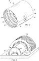
Figure 3 is an illustration of a perspective view of a half barrel part layup on a mandrel, ready to be moved into an autoclave for curing. -
Figure 4 is an illustration of a fragmentary, perspective view of a portion of the part layup shown inFigure 3 . -
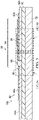
Figure 5 is an illustration of a sectional view taken along the line 5-5 inFigure 4 . -
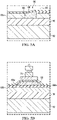
Figure 5A is an illustration of the area designated as "FIG. 5A " inFigure 5 . -
Figure 5B is an illustration of the area designated as "FIG. 5B " inFigure 5 . -
Figure 5C is an illustration similar toFigure 4 , but simplified and showing the location of the breathers in broken lines. -
Figure 6 is an illustration of a sectional view taken along the line 6-6 inFigure 4 . -
Figure 7 is an illustration of a sectional view similar toFigure 5 , but showing an alternate form of attachment of the edge seal to a caul. -
Figure 8 is an illustration of a sectional view similar toFigure 6 , but showing an alternate form of attachment of the edge seal to a caul. -
Figure 9 is an illustration of a sectional view showing a zipper forming part of the alternate form of attachment shown inFigures 7 and 8 . -
Figure 10 is an illustration of a sectional view showing one form of sealing a flap of the edge seal over an edge seal on an adjacent caul using magnets. -
Figure 11 is an illustration of a sectional view showing a further form of sealing the flap over an edge seal on an adjacent caul. -
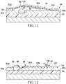
Figure 12 is an illustration of a sectional view showing another form of sealing the flap over an edge seal on an adjacent caul. -
Figure 13 is an illustration of a sectional view showing a further form of sealing the flap over an edge seal on an adjacent caul. -
Figure 14 is an illustration of a sectional view showing another form sealing the flap over an edge seal on an adjacent caul. -
Figure 15 is an illustration of a sectional view of one of the collapsible seals shown inFigure 14 , showing the seal in a collapsed condition. -
Figure 16 is an illustration of a sectional view of a further form of sealing a flap over and edge seal on an adjacent caul. -
Figure 17 is an illustration of a perspective view showing one form of sealing a T-joint in the edge seals. -
Figure 18 is an illustration of a bottom plan view of a clamp shown inFigure 17 . -
Figure 19 is an illustration of a perspective view showing a further form of sealing the T-joint in the edge seals. -
Figure 20 is an illustration of a flow diagram of a method of making a section of a composite barrel. -
Figure 21 is an illustration of a flow diagram of aircraft production and service methodology. -
Figure 22 is an illustration of a block diagram of an aircraft. - Referring first to
Figure 1 , anaircraft 40 includes afuselage 42,wings 44,horizontal stabilizers 46, and avertical stabilizer 48. In the illustrated example, thefuselage 42 is substantially cylindrical, however, in other examples the cross-sectional shape of the fuselage 22 may have an oval or similar cross sectional shape. Referring also toFigure 2 , thefuselage 42 may comprise a plurality ofbarrel sections 49 joined together end-to-end. Each of thebarrel sections 49 comprises barrel halves 51 joined together along abelt line 59, each of which comprises anouter skin 53 formed of a composite laminate and reinforced by circumferentially extending, longitudinally spacedframes 57, and longitudinally extendingstringers 55. Theouter skin 53, frames 57 andstringers 55 may each comprise a composite material, such as a carbon fiber reinforced plastic (CFRP) laminate. In other examples, thebarrel sections 49 may be produced as a single cylindrical structure, rather than in two barrel halves 51. - Referring now to
Figure 3 , in one production example, each of the barrel halves 51 is produced by laying up composite material on amandrel 52 that may be formed of a metal and has a half barrel shape. Layup of the composite material may be performed by automatic fiber placement machines (not shown) or similar robotic manipulators that lay down layers of composite tape or split tape over themandrel 52. Prior to laying up the composite material on themandrel 52,stringers 55 are placed in longitudinal recesses (not shown) in the surface of themandrel 52. With thestringers 55 having first been installed on themandrel 52, theouter skin 53 is then laid up on themandrel 52 in direct contact with thestringers 55. Theouter skin 53 and thestringers 55 are then cocured. For convenience of description, the outer skin laid up on themandrel 52 will sometimes be referred to herein as apart layup 50. - Referring to
Figures 3 and4 , following material layup, one ormore cauls part layup 50 in preparation for compacting and curing thepart layup 50 in anautoclave 58. Thecauls outer skin 53, while also applying even compaction pressure to thepart layup 50 under autoclave pressure. In the illustrated example, twocauls part layup 50, however in other examples, a single, half barrel shaped caul (not shown) may be placed over thepart layup 50. As will be discussed below in greater detail, thepart layup 50 and thecauls part layup 50 by sealing thecauls mandrel 52 usingedge seals Figure 4 ) which are clamped together and to themandrel 52. The edges seals 62a, 62b effectively form localized sealing zones between thecauls cauls mandrel 52. The combination of thecauls integrated edge seals part layup 50, thereby eliminating the need for a separate, all-encompassing vacuum bag, and saving the time required to install a vacuum bag, while reducing consumables. In some examples, themandrel 52 may comprise a full barrel shape, rather than a half barrel in which case cauls 60 are installed over the full barrel part layup and are sealed to each other and to themandrel 52. In fact, in some applications, depending on the size and geometry of thepart layup 50, n number of cauls 60 (e.g. 4, 6 or 8) may be installed and sealed over thepart layup 50. Moreover, the n number ofcauls 60 may be arranged side-by-side in the longitudinal direction 65 (Figure 4 ) as well as in thecircumferential direction 67 of thepart layup 50. As used herein the term "caul" is used in its broadest sense and is defined as any type of vacuum integral tooling that provides profile control and/or surface finish or treatment of the OML of thepart layup 50. - Attention is now directed to
Figures 4 ,5 and6 , which illustrate additional details showing how thecauls mandrel 52 in order to form a vacuum tight enclosure over thepart layup 50. Thecauls barrel sections 49 and are separated by agap 66, which allows them to expand relative to each other when heated to processing temperatures. Thecauls edge seals cauls cauls cauls part layup 50. Each of the edge seals 62a, 62b includes alongitudinal section 86 extending in alongitudinal direction 65 along thegap 66 between the twocauls circumferential section 88 extending in acircumferential direction 67 along the circumference of themandrel 52. Thelongitudinal sections 86 and thecircumferential sections 88 of the edge seals 62a, 62b intersect each other to form a T-junction 80. The edge seals 62a, 62b extend over the top ofvacuum ports 68 and pressure sensor ports 70 in themandrel 52 which are respectively used to draw and sense a vacuum beneath thecauls part layup 50. - Each of the edge seals and 62a, 62b is a strip of material comprising a relatively thin, flexible membrane-like elastomer, such as silicone rubber or Viton© that is sufficiently durable to permit repeated use. The ability to reuse the edge seals 62a, 62b and the fact that they are permanently attached to the
cauls longitudinal section 86 ofedge seals 62a includes aflap 64 that overlaps thelongitudinal section 86 of theadjacent edge seal 62b, and spans thegap 66 between thecauls - A filler 98 (
Figure 5 ) formed from a suitable material such as an elastomer is placed in thegap 66 to prevent undesired sagging of theflap 64 within thegap 66 during autoclave processing, and to apply compaction pressure to thepart layup 50 across thegap 66. Use of thefiller 98 results in even compaction pressure being applied to thepart layup 50 between thecauls gap 66.Figure 5A shows thefiller 98 having been compressed by theflap 64 due to vacuum and/or autoclave pressure, causing thefiller 98 to deform, fill thegap 66, and apply compaction pressure to thepart layup 50 between thecauls breather 90 is placed between theflap 64 and theunderlying edge seal 62b to allow escape of air and volatiles from thepart layup 50, and to assist in spreading the vacuum applied to thepart layup 50 throughout the area beneath thecauls - In one example, shown in
Figure 5B , a vacuum source (not shown) may be coupled to the longitudinally extending edge seals 62a over thebreathers 90 using a vacuum fitting 75 that is external. The vacuum source that is coupled with the vacuum fitting 75 may be any suitable vacuum generating device, including those normally used to evacuate typical vacuum bags. The vacuum fitting 75 allows a vacuum to be applied through thebreather 90 to those areas beneath theedge seal 62a, or in other words, to those areas that are not covered by thecauls 60. If desired, the vacuum fitting 75 may be integrated into theedge seal 62a such that it remains attached to theedge seal 62a and thus may be reused when thecauls 60 are removed from thepart layup 50. Referring toFigure 5C , in another example, thebreather 90 may extend longitudinally beyond the outer edges of thecauls 60, onto themandrel 52 so that it overlies one or more of thevacuum ports 68 in themandrel 52. In this example, air and volatiles are drawn through thebreather 90 into thevacuum ports 68 where vacuum is applied. As is also shown inFigure 5C , thebreather 90 may be extended longitudinally beyond thecauls 60 to intersectbreather 92 at the T-junction, allowing a vacuum to be drawn beneath bothedge seals vacuum ports 68 in themandrel 52. The longitudinal extension of thebreather 90 in this manner allows a vacuum to be applied through both of thebreathers edge seal cauls 60. - Referring to
Figures 4 and5 , theinboard side 82 of theedge seal 62a is adhesively attached around its entire perimeter to theunderlying caul 60a along anadhesive bond line 72. Likewise,edge seal 62b is adhesively attached around its entire perimeter to theunderlying caul 60b along anadhesive bond line 74. Other techniques for attaching the edge seals 62a, 62b to thecauls - Referring to
Figures 4 and6 , thecircumferential sections 88 of the edge seals 62a, 62b are draped down over the outer edges of thecauls mandrel 52, including aramp 96 along theouter periphery 106 of themandrel 52.Breather 92 andbreather 94 are provided between thecircumferential sections 88 of the edge seals 62a, 62b, and theunderlying mandrel 52, typically located above the vacuum ports 68 (Figure 4 ) to allow the escape of the air, and volatiles during processing. In one example,breather 92 andbreather 94 as well as breather 90 (Figure 5 ) may comprise individual pieces that are installed separate from the edge seals 62a, 62b that cover them. However, in other examples,breather 90,breather 92 andbreather 94 may be integrated into the edge seals 62a, 62b, as by molding. As will be discussed below in more detail, theflap 64 is sealed to the underlying longitudinal section of theedge seal 62b by any of a variety of clamping techniques. Similarly, thecircumferential sections 88 of bothedge seals 62a, 52b are sealed to themandrel 52 using any of a variety of clamping techniques. - In the example shown in
Figures 4-6 , the edge seals 62a, 62b are permanently attached to theunderlying cauls adhesive bond lines cauls 60 and their edge seals 62 to be removed together as an assembly. However some applications it may be desirable to have the ability to easily remove the edge seals 62a, 62b for any of various reasons. One technique for removably attaching the edge seals 62a, 62b to thecauls 60a, 69b is illustrated inFigures 7, 8 , and9 . In this example,zippers 108 are employed to releasably attach the inner edges of theedge seal 62a to thecaul 60a. Thezippers 108 each comprises a firsttoothed member 112 attached by a layer of adhesive 116 to theunderlying caul 60a, and a secondtoothed member 110 similarly attached to theedge seal 62a. Each oftoothed member 110 andtoothed member 112, may be formed of any suitable material such as silicone.Toothed member 110 andtoothed member 112 friction fit together in interlocking relationship. In some examples, it may be necessary or desirable to provide afiller ramp 114 along an edge of thezipper 108 in order to smoothly ramp down theedge seal 62a from thezipper 108 to the surface of thecaul 60a. The use of azipper 108 allows theedge seal 62a to be easily removed when desired for cleaning, repair, and/or replacement. Other techniques for releasably attaching theedge seal 62a to thecaul 60a are possible. In some examples, azipper 108 may also be used to releasably attach either or both of the edge seals 62a, 62b to acaul 60 that is adjacent or to themandrel 52. For example, inFigure 7 theflap 64 may be releasably attached and sealed to thecaul 60b by a zipper 108 (not shown), and inFigures 8 , the outer edge 104 (Figure 6 ) of theedge seal 62a may be similarly releasably attached and sealed to thecaul 60b by azipper 108. - A wide variety of techniques can be employed to releasably clamp or attach the
flap 64 ofedge seal 62a down over theedge seal 62b in order to form a vacuum tight seal between these twoedge seals mandrel 52. For example, referring toFigure 10 , theouter end 84 of theflap 64 can be permanently attached to a carbonfiber mounting strip 122 that is bonded by a layer of adhesive 124 tocaul 60a. Theouter end 84 of theflap 64 can be clamped tocaul 60b by a series ofmagnets 118 and/or ferromagnetic materials that are placed on top of or embedded into theflap 64. Themagnets 118 are attracted to themandrel 52 or to ferromagnetic materials (not shown) embedded in themandrel 52, thereby clapping theflap 64 down against thecaul 60b. In some applications, it may also be possible to attach theedge seal 62a to thecaul 60a using magnets 118 in lieu of the use of an adhesive. -
Figure 11 illustrates another form of clamping devices in whichspring members 130 such as carbon fiber stiffeners are bonded to theouter end 84 of theflap 64. It may be possible to fabricate thespring member 130 from materials other than carbon fiber, such as spring steel. Thespring member 130 has a preformed curved shape that causes theouter extremities 64a of theflap 64 to be forced down onto positive engagement and seal against thecaul 60b. -
Figure 12 illustrates another technique for sealing theflap 64 against thecaul 60b. In this example, astrip 132 of flexible spring material, such as a metal or carbon fiber is attached by adhesive 134 to thecaul 60b. Thestrip 132 forces apressure concentrator 136 such as a rod-like member which forces theouter end 84 of theflap 64 to seal against theedge seal 62b. - A further example of sealing the
flap 64 against thecaul 60b is shown inFigure 13 . In this example, theouter end 84 of theflap 64 includes astiffener 142 secured by a layer of adhesive 144 to aflexible seal 146 having the cross sectional shape of an inverted "7". Aninflatable hose 140 is positioned between the top of theflap 64, and astrongback 138 which may comprise, for example and without limitation, a rigid frame. Inflation of thehose 140 forces theflap 64 downwardly, causing theflexible seal 146 to collapse and form a vacuum tight seal between theflap 64 and theedge seal 62b. Alternatively, thestrongback 138 may be displaced downwardly, causing apreinflated hose 140 to force theflexible seal 146 to collapse. - Referring to
Figures 14 and15 , in another example, a pair of theflexible seals 146 are positioned at spaced apart locations between theflap 64 and theedge seal 62b. In this example, theflexible seals 146 are subjected to a vacuum and act as vacuum chucks which draw down theflap 64, causing theflexible seals 146 to collapse (seeFigure 15 ) against theedge seal 62b, creating a vacuum tight seal between the edge seals 62a and 62b. - Attention is now directed to
Figure 16 , which illustrates another example of a technique for sealing theflap 64 against theedge seal 62b. In this example, rather than overlapping theflap 64 over theedge seal 62b, theouter end 84 of theflap 64 and theinner end 100 of theedge seal 62b are arranged in face-to-face relationship and are seal together withmagnets 148 or other means, such as a clamp (not shown). Aspacer 170 may be placed between the ends of theflap 64 and theedge seal 62b to maintain their face-to-face orientation. - Referring to
Figure 17 and 18 , thelongitudinal section 86 and thecircumferential section 88 of the edge seals 62a, 62b intersect at a T-junction 80 as previously mentioned. In order to assure that there is no air leakage at the T-junction 80, aclamp 172 may be provided to force the twoedge seal mandrel 52 at the T-junction. Theclamp 172 may comprise any of a number of mechanisms, but in the illustrated example, comprises atoggle mechanism 164. The toggle mechanism includes a base 160 mounted on themandrel 52 and apressure plate 158. The bottom of thepressure plate 158 includes a rectangular, gasket-like seal 162. Thetoggle mechanism 164 forces thepressure plate 158 downwardly, causing the gasket-like seal 162 to apply pressure at the T-junction 80, thereby creating a tight seal at this location between the edge seals 62a and 62b. -
Figure 19 illustrates another example of a technique for assuring that air leaks do not occur at the T-junction 80. In this example, avacuum bag 166 is placed over the area of the T-junction and sealed to theunderlying edge seals sealant 168. - Attention is now directed to
Figure 20 , which broadly illustrates the steps of a method of making at least a section of a compositebarrel using cauls 60 having the edge seals 62 described above. Beginning at 171, a composite barrel layup is formed on amandrel 52. At 174, at least afirst caul 60a is placed on the composite barrel layup. At 176, a vacuum tight seal is formed between thefirst caul 60a and themandrel 52, thereby creating a local sealing zone. The seal at 176 may be formed by sealing the perimeter of the caul to themandrel 52, as by sealing a strip of elastomeric material to the caul. Although not shown inFigure 20 , as previously described,cauls 60 may be installed on the composite barrel layup and sealed to themandrel 52 and to each other using edge seals 62 that create localized sealing zones. - Examples of the disclosure may find use in a variety of potential applications, particularly in the transportation industry, including for example, aerospace, marine, and other applications where vacuum bag compaction of composite part layups utilize cauls. Thus, referring now to
Figures 21 and 22 , examples of the disclosure may be used in the context of an aircraft manufacturing andservice method 182 as shown inFigure 21 and anaircraft 184 as shown inFigure 22 . Aircraft applications of the disclosed examples may include a variety of composite parts and structures, including sections of afuselage 201. During pre-production, exemplary manufacturing andservice method 182 may include specification anddesign 186 of theaircraft 184 andmaterial procurement 188. During production, component andsubassembly manufacturing 190 andsystem integration 192 of the aircraft takes place. Thereafter, theaircraft 184 may go through certification anddelivery 194 in order to be placed inservice 196. While in service by a customer, theaircraft 184 is scheduled for routine maintenance andservice 198, which may also include modification, reconfiguration, refurbishment, and so on. The disclosed embodiments may be used in one or more ofproduction process 190 or production process, or in theairframe 200 or in thefuselage 201. - Each of the processes of manufacturing and
service method 182 may be performed or carried out by a system integrator, a third party, and/or an operator (e.g., a customer). For the purposes of this description, a system integrator may include without limitation any number of aircraft manufacturers and major-system subcontractors; a third party may include without limitation any number of vendors, subcontractors, and suppliers; and an operator may be an airline, leasing company, military entity, service organization, and so on. - As shown in
Figure 22 , theaircraft 184 produced by exemplary manufacturing andservice method 182 may include anairframe 200 having afuselage 201, a plurality ofhigh level systems 202 and an interior 204. Examples of high-level systems 202 include one or more of apropulsion system 206, anelectrical system 208, ahydraulic system 210 and anenvironmental system 212. Any number of other systems may be included. Although an aerospace example is shown, the principles of the disclosure may be applied to other industries, such as the marine and automotive industries. - Systems and methods embodied herein may be employed during any one or more of the stages of the manufacturing and
service method 182. For example, components or subassemblies corresponding toproduction process 190 may be fabricated or manufactured in a manner similar to components or subassemblies produced while theaircraft 184 is in service. Also, one or more apparatus examples, method examples, or a combination thereof may be utilized duringproduction process 190 andproduction process 192, for example, by substantially expediting assembly of or reducing the cost of anaircraft 184. Similarly, one or more of apparatus examples, method examples, or a combination thereof may be utilized while theaircraft 184 is in service, for example and without limitation, to maintenance andservice 198. - As used herein, the phrase "at least one of", when used with a list of items, means different combinations of one or more of the listed items may be used and only one of each item in the list may be needed. For example, "at least one of item A, item B, and item C" may include, without limitation, item A, item A and item B, or item B. This example also may include item A, item B, and item C or item B and item C. The item may be a particular object, thing, or a category. In other words, at least one of means any combination items and number of items may be used from the list but not all of the items in the list are required.
- 1. An apparatus for sealing a caul (60) over a composite part layup (50) on a tool (52), comprising:
an edge seal (62) extending around a perimeter (76) of the caul (60) and configured to form a vacuum tight seal between the caul (60) and the tool (52). - 2. The apparatus of clause 1, wherein the edge seal (62) is permanently attached to the caul (60) and is removably attached to the tool (52) to allow the caul (60) and the edge seal (62) to be removed together from the tool (52).
- 3. The apparatus according to Clauses 1 or 2 wherein the edge seal (62) includes a strip of material that overlaps the perimeter (76) of the caul (60) and a portion of the tool (52).
- 4. The apparatus according to any of clauses 1 to 3 wherein the edge seal (62) is adhesively bonded to the caul (60) .
- 5. The apparatus according to any of clauses 1 to 4 wherein the edge seal (62) includes a flexible membrane configured to be formed over the caul (60) and onto the tool (52) .
- 6. The apparatus according to any of clauses 1 to 5, further comprising a clamp (118, 130, 132) configured to clamp the edge seal (62) to the tool (52).
- 7. An apparatus for sealing at least first and second cauls (60a, 60b) over a composite barrel part layup (50) on a mandrel (52), comprising:
- a first edge seal (62a) extending around a perimeter (76) of the first caul (60a) and configured to form a vacuum tight seal between the first caul (60a) and the mandrel (52); and
- a second edge seal (62b) extending around a perimeter (76) of the second caul (60b) and configured to form a vacuum tight seal between the second caul (60b) and the mandrel (52),
- wherein the first and second edge seals (62a, 62b) overlap and are configured to form a vacuum tight seal between the first and second cauls (60a, 60b).
- 8. The apparatus of clause 7, wherein the first edge seal (62a) is attached to the first caul (60a) and includes a flap (64) configured to be placed over and sealed to the second edge seal (62b).
- 9. The apparatus according to Clauses 7 or 8, wherein:
- the first edge seal (62a) includes a longitudinally extending section (86) and a circumferentially extending section (88), and
- the second edge seal (62b) includes a longitudinally extending section (86) and a circumferentially extending section (88),
- wherein the circumferentially extending section (88) of each of the first and second cauls (60a, 60b) overlaps and is sealed to the mandrel (52).
- 10. The apparatus according to any of clauses 7 to 9, wherein the first edge seal (62a) is configured to remain attached to the first caul (60a) upon removal of the first caul (60a) from the composite barrel part layup (50).
- 11. The apparatus according to any of clauses 7 to 10, wherein the first edge seal (62a) includes a flap (64) configured to overlie the second edge seal (62b).
- 12. The apparatus of clause 11, including a clamp (118, 130, 132) configured to clamp and seal the flap (64) against the second edge seal (62b).
- 13. The apparatus of clause 12, wherein the clamp includes magnets (118) on the flap (64) configured to be attracted to the mandrel (52) and clamp the flap (64) against the first edge seal (62a).
- 14. The apparatus according to Clauses 12 or 13, wherein the clamp includes carbon fiber stiffeners (130) attached to and extending across the flap (64), the carbon fiber stiffeners (130) being configured to press the flap (64) down into positive engagement with the second edge seal (62b).
- 15. The apparatus according to any of clauses 12 to 14, wherein the clamp comprises a plurality of collapsible seals (146) interposed between the flap (64) and the second edge seal (62b) and configured to press the flap (64) down into positive engagement with the second edge seal (62b).
- 16. A method of making at least a section (49) of a composite barrel, comprising:
- forming a composite barrel part layup (50) on a mandrel (52);
- placing at least a first caul (60a) on the composite barrel part layup (50); and
forming a vacuum tight seal between the first caul (60a) and the mandrel (52), including sealing a perimeter of the first caul (60a) to the mandrel (52).
- 17. The method of clause 16, wherein forming a vacuum tight seal includes sealing a strip (62a) of elastomeric material around the perimeter (76) of the first caul (60a).
- 18. The method according to Clauses 16 or 17, further comprising:
- placing at least a second caul (60b) on the composite barrel part layup (50);
- forming a vacuum tight seal between the second caul (60b) and the mandrel (52), including sealing a perimeter (76) of the second caul (60b) to the mandrel (52); and
- forming a vacuum tight seal between the first caul (60a) and the second caul (60b), including sealing a perimeter (76) of the second caul (60b) to a perimeter (76) of the first caul (60a).
- 19. The method of clause 18, wherein forming a vacuum tight seal between the first caul (60a) and the second caul (60b) includes:
- sealing an edge seal (62a) to a perimeter (76) of first caul (60a),
- overlapping the edge seal (62a) over the perimeter (76) of the second caul (60b), and
- sealing the edge seal (62a) to the second caul (60b).
- 20. The method according to Clauses 18 or 19, wherein forming a vacuum tight seal includes:
integrating edge seals (62a, 62b) around the perimeters (76) of each of the first and second cauls (60a, 60b);,- using the edge seals (62a, 62b) to form a vacuum tight seal between the first and second cauls (60a, 60b); and
- using the edge seals (62a, 62b) to form a vacuum tight seal between the first and second cauls (62a, 62b), and the mandrel (52) .
- The description of the different illustrative examples has been presented for purposes of illustration and description, and is not intended to be exhaustive or limited to the examples in the form disclosed. Many modifications and variations will be apparent to those of ordinary skill in the art. Further, different illustrative examples may provide different advantages as compared to other illustrative examples. The example or examples selected are chosen and described in order to best explain the principles of the examples, the practical application, and to enable others of ordinary skill in the art to understand the disclosure for various examples with various modifications as are suited to the particular use contemplated.
Claims (15)
- An apparatus for sealing at least first and second cauls (60a, 60b) over a composite barrel part layup (50) on a mandrel (52), comprising:a first edge seal (62a) extending around a perimeter (76) of the first caul (60a) and configured to form a vacuum tight seal between the first caul (60a) and the mandrel (52); anda second edge seal (62b) extending around a perimeter (76) of the second caul (60b) and configured to form a vacuum tight seal between the second caul (60b) and the mandrel (52),wherein the first and second edge seals (62a, 62b) overlap and are configured to form a vacuum tight seal between the first and second cauls (60a, 60b).
- The apparatus of claim 1, wherein the first edge seal (62a) is attached to the first caul (60a) and includes a flap (64) configured to be placed over and sealed to the second edge seal (62b).
- The apparatus according to Claimslor2, wherein:the first edge seal (62a) includes a longitudinally extending section (86) and a circumferentially extending section (88), andthe second edge seal (62b) includes a longitudinally extending section (86) and a circumferentially extending section (88),wherein the circumferentially extending section (88) of each of the first and second cauls (60a, 60b) overlaps and is sealed to the mandrel (52).
- The apparatus according to any of claims 1 to 3, wherein the first edge seal (62a) is configured to remain attached to the first caul (60a) upon removal of the first caul (60a) from the composite barrel part layup (50).
- The apparatus according to any of claims 1 to 4, wherein the first edge seal (62a) includes a flap (64) configured to overlie the second edge seal (62b).
- The apparatus of claim 5, including a clamp (118, 130, 132) configured to clamp and seal the flap (64) against the second edge seal (62b).
- The apparatus of claim 6, wherein the clamp includes magnets (118) on the flap (64) configured to be attracted to the mandrel (52) and clamp the flap (64) against the first edge seal (62a).
- The apparatus according to Claims 6 or 7, wherein the clamp includes carbon fiber stiffeners (130) attached to and extending across the flap (64), the carbon fiber stiffeners (130) being configured to press the flap (64) down into positive engagement with the second edge seal (62b).
- The apparatus according to any of claims 6 to 8, wherein the clamp comprises a plurality of collapsible seals (146) interposed between the flap (64) and the second edge seal (62b) and configured to press the flap (64) down into positive engagement with the second edge seal (62b).
- The apparatus according to any of claims 1 to 9, wherein an edge seal (62) extending around a perimeter (76) of the caul (60) and configured to form a vacuum tight seal between the caul (60) and the tool (52).
- A method of making at least a section (49) of a composite barrel, comprising:forming a composite barrel part layup (50) on a mandrel (52) ;placing at least a first caul (60a) on the composite barrel part layup (50); andforming a vacuum tight seal between the first caul (60a) and the mandrel (52), including sealing a perimeter of the first caul (60a) to the mandrel (52).
- The method of claim 11, wherein forming a vacuum tight seal includes sealing a strip (62a) of elastomeric material around the perimeter (76) of the first caul (60a).
- The method according to Claims 11 or 12, further comprising:placing at least a second caul (60b) on the composite barrel part layup (50);forming a vacuum tight seal between the second caul (60b) and the mandrel (52), including sealing a perimeter (76) of the second caul (60b) to the mandrel (52); andforming a vacuum tight seal between the first caul (60a) and the second caul (60b), including sealing a perimeter (76) of the second caul (60b) to a perimeter (76) of the first caul (60a).
- The method of claim 13, wherein forming a vacuum tight seal between the first caul (60a) and the second caul (60b) includes:sealing an edge seal (62a) to a perimeter (76) of first caul (60a),overlapping the edge seal (62a) over the perimeter (76) of the second caul (60b), andsealing the edge seal (62a) to the second caul (60b).
- The method according to Claims 13 or 14, wherein forming a vacuum tight seal includes:integrating edge seals (62a, 62b) around the perimeters (76) of each of the first and second cauls (60a, 60b);using the edge seals (62a, 62b) to form a vacuum tight seal between the first and second cauls (60a, 60b); andusing the edge seals (62a, 62b) to form a vacuum tight seal between the first and second cauls (62a, 62b), and the mandrel (52) .
Applications Claiming Priority (1)
| Application Number | Priority Date | Filing Date | Title |
|---|---|---|---|
| US202163201135P | 2021-04-14 | 2021-04-14 |
Publications (2)
| Publication Number | Publication Date |
|---|---|
| EP4074497A1 true EP4074497A1 (en) | 2022-10-19 |
| EP4074497B1 EP4074497B1 (en) | 2024-09-18 |
Family
ID=80928900
Family Applications (1)
| Application Number | Title | Priority Date | Filing Date |
|---|---|---|---|
| EP22163390.2A Active EP4074497B1 (en) | 2021-04-14 | 2022-03-21 | Cauls having integrated edge seals and sealing method |
Country Status (2)
| Country | Link |
|---|---|
| US (1) | US12011889B2 (en) |
| EP (1) | EP4074497B1 (en) |
Citations (2)
| Publication number | Priority date | Publication date | Assignee | Title |
|---|---|---|---|---|
| US6431850B1 (en) * | 2000-08-11 | 2002-08-13 | General Electric Company | Composite caul sheet with integral seal used in the fabrication of lightweight airfoils and method of making |
| EP2939819A1 (en) * | 2014-04-28 | 2015-11-04 | Airbus Operations, S.L. | Method for manufacturing pieces of composite material by vacuum-baggiing |
Family Cites Families (8)
| Publication number | Priority date | Publication date | Assignee | Title |
|---|---|---|---|---|
| US20080083493A1 (en) * | 2006-10-10 | 2008-04-10 | Ridges Michael D | Reusable mechanical fastener and vacuum seal combination |
| US8333864B2 (en) | 2008-09-30 | 2012-12-18 | The Boeing Company | Compaction of prepreg plies on composite laminate structures |
| US20120025437A1 (en) * | 2010-07-29 | 2012-02-02 | Allred & Associates Inc. | Lightweight carbon fiber c-clamp |
| US8940222B2 (en) * | 2011-11-03 | 2015-01-27 | The Boeing Company | High flow edge breather and method |
| US8684343B2 (en) | 2012-01-06 | 2014-04-01 | Rubbercraft Corporation Of California Ltd | Composite fabrication vent assembly and method |
| WO2016090064A1 (en) | 2014-12-05 | 2016-06-09 | Advanced Electrophoresis Solutions Ltd | Apparatus and method for separating molecules |
| US11073027B2 (en) * | 2018-05-17 | 2021-07-27 | Raytheon Technologies Corporation | Mold tool and methods for airfoil bonding |
| US11220353B2 (en) | 2019-04-18 | 2022-01-11 | The Boeing Company | Method of fabricating a composite structure |
-
2022
- 2022-01-31 US US17/649,424 patent/US12011889B2/en active Active
- 2022-03-21 EP EP22163390.2A patent/EP4074497B1/en active Active
Patent Citations (2)
| Publication number | Priority date | Publication date | Assignee | Title |
|---|---|---|---|---|
| US6431850B1 (en) * | 2000-08-11 | 2002-08-13 | General Electric Company | Composite caul sheet with integral seal used in the fabrication of lightweight airfoils and method of making |
| EP2939819A1 (en) * | 2014-04-28 | 2015-11-04 | Airbus Operations, S.L. | Method for manufacturing pieces of composite material by vacuum-baggiing |
Also Published As
| Publication number | Publication date |
|---|---|
| US20220332064A1 (en) | 2022-10-20 |
| US12011889B2 (en) | 2024-06-18 |
| EP4074497B1 (en) | 2024-09-18 |
Similar Documents
| Publication | Publication Date | Title |
|---|---|---|
| CN108943768B (en) | Flexible vacuum attachment of objects to complex surfaces | |
| US7228611B2 (en) | Method of transferring large uncured composite laminates | |
| CA2835892C (en) | Method and device for transporting, placing and compacting composite stiffeners | |
| EP2671709B1 (en) | Non-vented bladder system for curing composite parts | |
| EP2821210B1 (en) | Vacuum bag processing of composite parts using a conformable vacuum bag assembly | |
| US9862154B2 (en) | Apparatuses and methods for efficient sealing of vacuum bag seams | |
| US20170008198A1 (en) | Composite Tool Having Vacuum Integrity and Method of Making the Same | |
| US10766212B2 (en) | Method and apparatus for forming radius filler kits | |
| EP2982496B1 (en) | Bladder system for curing composite parts | |
| EP3613567B1 (en) | Flexible mandrel for forming composite structures | |
| EP4074498B1 (en) | Apparatus and method for processing a composite structure | |
| US12011889B2 (en) | Cauls having integrated edge seals and sealing method | |
| US20240262055A1 (en) | Integrated Caul with Elastomeric Seals | |
| US20220152956A1 (en) | Caul Plate System for Aircraft Fabrication | |
| EP4477378A1 (en) | Vacuum bag sealing system | |
| EP3023231B1 (en) | Systems and methods for compacting a charge of composite material | |
| EP4491382A1 (en) | Curing tool assemblies, methods and systems for composite manufacturing | |
| EP4011606A2 (en) | Caul plate system for aircraft fabrication |
Legal Events
| Date | Code | Title | Description |
|---|---|---|---|
| PUAI | Public reference made under article 153(3) epc to a published international application that has entered the european phase |
Free format text: ORIGINAL CODE: 0009012 |
|
| STAA | Information on the status of an ep patent application or granted ep patent |
Free format text: STATUS: THE APPLICATION HAS BEEN PUBLISHED |
|
| AK | Designated contracting states |
Kind code of ref document: A1 Designated state(s): AL AT BE BG CH CY CZ DE DK EE ES FI FR GB GR HR HU IE IS IT LI LT LU LV MC MK MT NL NO PL PT RO RS SE SI SK SM TR |
|
| RAP3 | Party data changed (applicant data changed or rights of an application transferred) |
Owner name: THE BOEING COMPANY |
|
| STAA | Information on the status of an ep patent application or granted ep patent |
Free format text: STATUS: REQUEST FOR EXAMINATION WAS MADE |
|
| 17P | Request for examination filed |
Effective date: 20230401 |
|
| RBV | Designated contracting states (corrected) |
Designated state(s): AL AT BE BG CH CY CZ DE DK EE ES FI FR GB GR HR HU IE IS IT LI LT LU LV MC MK MT NL NO PL PT RO RS SE SI SK SM TR |
|
| GRAP | Despatch of communication of intention to grant a patent |
Free format text: ORIGINAL CODE: EPIDOSNIGR1 |
|
| STAA | Information on the status of an ep patent application or granted ep patent |
Free format text: STATUS: GRANT OF PATENT IS INTENDED |
|
| INTG | Intention to grant announced |
Effective date: 20231208 |
|
| GRAJ | Information related to disapproval of communication of intention to grant by the applicant or resumption of examination proceedings by the epo deleted |
Free format text: ORIGINAL CODE: EPIDOSDIGR1 |
|
| STAA | Information on the status of an ep patent application or granted ep patent |
Free format text: STATUS: REQUEST FOR EXAMINATION WAS MADE |
|
| GRAP | Despatch of communication of intention to grant a patent |
Free format text: ORIGINAL CODE: EPIDOSNIGR1 |
|
| STAA | Information on the status of an ep patent application or granted ep patent |
Free format text: STATUS: GRANT OF PATENT IS INTENDED |
|
| INTC | Intention to grant announced (deleted) | ||
| INTG | Intention to grant announced |
Effective date: 20240426 |
|
| GRAS | Grant fee paid |
Free format text: ORIGINAL CODE: EPIDOSNIGR3 |
|
| GRAA | (expected) grant |
Free format text: ORIGINAL CODE: 0009210 |
|
| STAA | Information on the status of an ep patent application or granted ep patent |
Free format text: STATUS: THE PATENT HAS BEEN GRANTED |
|
| AK | Designated contracting states |
Kind code of ref document: B1 Designated state(s): AL AT BE BG CH CY CZ DE DK EE ES FI FR GB GR HR HU IE IS IT LI LT LU LV MC MK MT NL NO PL PT RO RS SE SI SK SM TR |
|
| REG | Reference to a national code |
Ref country code: GB Ref legal event code: FG4D |
|
| REG | Reference to a national code |
Ref country code: CH Ref legal event code: EP |
|
| REG | Reference to a national code |
Ref country code: IE Ref legal event code: FG4D |
|
| REG | Reference to a national code |
Ref country code: DE Ref legal event code: R096 Ref document number: 602022006119 Country of ref document: DE |
|
| P01 | Opt-out of the competence of the unified patent court (upc) registered |
Free format text: CASE NUMBER: APP_53039/2024 Effective date: 20240923 |
|
| REG | Reference to a national code |
Ref country code: LT Ref legal event code: MG9D |
|
| PG25 | Lapsed in a contracting state [announced via postgrant information from national office to epo] |
Ref country code: NO Free format text: LAPSE BECAUSE OF FAILURE TO SUBMIT A TRANSLATION OF THE DESCRIPTION OR TO PAY THE FEE WITHIN THE PRESCRIBED TIME-LIMIT Effective date: 20241218 |
|
| PG25 | Lapsed in a contracting state [announced via postgrant information from national office to epo] |
Ref country code: GR Free format text: LAPSE BECAUSE OF FAILURE TO SUBMIT A TRANSLATION OF THE DESCRIPTION OR TO PAY THE FEE WITHIN THE PRESCRIBED TIME-LIMIT Effective date: 20241219 Ref country code: FI Free format text: LAPSE BECAUSE OF FAILURE TO SUBMIT A TRANSLATION OF THE DESCRIPTION OR TO PAY THE FEE WITHIN THE PRESCRIBED TIME-LIMIT Effective date: 20240918 |
|
| PG25 | Lapsed in a contracting state [announced via postgrant information from national office to epo] |
Ref country code: BG Free format text: LAPSE BECAUSE OF FAILURE TO SUBMIT A TRANSLATION OF THE DESCRIPTION OR TO PAY THE FEE WITHIN THE PRESCRIBED TIME-LIMIT Effective date: 20240918 |
|
| PG25 | Lapsed in a contracting state [announced via postgrant information from national office to epo] |
Ref country code: LV Free format text: LAPSE BECAUSE OF FAILURE TO SUBMIT A TRANSLATION OF THE DESCRIPTION OR TO PAY THE FEE WITHIN THE PRESCRIBED TIME-LIMIT Effective date: 20240918 |
|
| PG25 | Lapsed in a contracting state [announced via postgrant information from national office to epo] |
Ref country code: HR Free format text: LAPSE BECAUSE OF FAILURE TO SUBMIT A TRANSLATION OF THE DESCRIPTION OR TO PAY THE FEE WITHIN THE PRESCRIBED TIME-LIMIT Effective date: 20240918 |
|
| REG | Reference to a national code |
Ref country code: NL Ref legal event code: MP Effective date: 20240918 |
|
| PG25 | Lapsed in a contracting state [announced via postgrant information from national office to epo] |
Ref country code: RS Free format text: LAPSE BECAUSE OF FAILURE TO SUBMIT A TRANSLATION OF THE DESCRIPTION OR TO PAY THE FEE WITHIN THE PRESCRIBED TIME-LIMIT Effective date: 20241218 |
|
| PG25 | Lapsed in a contracting state [announced via postgrant information from national office to epo] |
Ref country code: RS Free format text: LAPSE BECAUSE OF FAILURE TO SUBMIT A TRANSLATION OF THE DESCRIPTION OR TO PAY THE FEE WITHIN THE PRESCRIBED TIME-LIMIT Effective date: 20241218 Ref country code: NO Free format text: LAPSE BECAUSE OF FAILURE TO SUBMIT A TRANSLATION OF THE DESCRIPTION OR TO PAY THE FEE WITHIN THE PRESCRIBED TIME-LIMIT Effective date: 20241218 Ref country code: LV Free format text: LAPSE BECAUSE OF FAILURE TO SUBMIT A TRANSLATION OF THE DESCRIPTION OR TO PAY THE FEE WITHIN THE PRESCRIBED TIME-LIMIT Effective date: 20240918 Ref country code: HR Free format text: LAPSE BECAUSE OF FAILURE TO SUBMIT A TRANSLATION OF THE DESCRIPTION OR TO PAY THE FEE WITHIN THE PRESCRIBED TIME-LIMIT Effective date: 20240918 Ref country code: GR Free format text: LAPSE BECAUSE OF FAILURE TO SUBMIT A TRANSLATION OF THE DESCRIPTION OR TO PAY THE FEE WITHIN THE PRESCRIBED TIME-LIMIT Effective date: 20241219 Ref country code: FI Free format text: LAPSE BECAUSE OF FAILURE TO SUBMIT A TRANSLATION OF THE DESCRIPTION OR TO PAY THE FEE WITHIN THE PRESCRIBED TIME-LIMIT Effective date: 20240918 Ref country code: BG Free format text: LAPSE BECAUSE OF FAILURE TO SUBMIT A TRANSLATION OF THE DESCRIPTION OR TO PAY THE FEE WITHIN THE PRESCRIBED TIME-LIMIT Effective date: 20240918 |
|
| REG | Reference to a national code |
Ref country code: AT Ref legal event code: MK05 Ref document number: 1724347 Country of ref document: AT Kind code of ref document: T Effective date: 20240918 |
|
| PG25 | Lapsed in a contracting state [announced via postgrant information from national office to epo] |
Ref country code: NL Free format text: LAPSE BECAUSE OF FAILURE TO SUBMIT A TRANSLATION OF THE DESCRIPTION OR TO PAY THE FEE WITHIN THE PRESCRIBED TIME-LIMIT Effective date: 20240918 |
|
| PG25 | Lapsed in a contracting state [announced via postgrant information from national office to epo] |
Ref country code: IS Free format text: LAPSE BECAUSE OF FAILURE TO SUBMIT A TRANSLATION OF THE DESCRIPTION OR TO PAY THE FEE WITHIN THE PRESCRIBED TIME-LIMIT Effective date: 20250118 Ref country code: PT Free format text: LAPSE BECAUSE OF FAILURE TO SUBMIT A TRANSLATION OF THE DESCRIPTION OR TO PAY THE FEE WITHIN THE PRESCRIBED TIME-LIMIT Effective date: 20250120 |
|
| PG25 | Lapsed in a contracting state [announced via postgrant information from national office to epo] |
Ref country code: RO Free format text: LAPSE BECAUSE OF FAILURE TO SUBMIT A TRANSLATION OF THE DESCRIPTION OR TO PAY THE FEE WITHIN THE PRESCRIBED TIME-LIMIT Effective date: 20240918 Ref country code: SM Free format text: LAPSE BECAUSE OF FAILURE TO SUBMIT A TRANSLATION OF THE DESCRIPTION OR TO PAY THE FEE WITHIN THE PRESCRIBED TIME-LIMIT Effective date: 20240918 |
|
| PG25 | Lapsed in a contracting state [announced via postgrant information from national office to epo] |
Ref country code: ES Free format text: LAPSE BECAUSE OF FAILURE TO SUBMIT A TRANSLATION OF THE DESCRIPTION OR TO PAY THE FEE WITHIN THE PRESCRIBED TIME-LIMIT Effective date: 20240918 |
|
| PG25 | Lapsed in a contracting state [announced via postgrant information from national office to epo] |
Ref country code: AT Free format text: LAPSE BECAUSE OF FAILURE TO SUBMIT A TRANSLATION OF THE DESCRIPTION OR TO PAY THE FEE WITHIN THE PRESCRIBED TIME-LIMIT Effective date: 20240918 Ref country code: EE Free format text: LAPSE BECAUSE OF FAILURE TO SUBMIT A TRANSLATION OF THE DESCRIPTION OR TO PAY THE FEE WITHIN THE PRESCRIBED TIME-LIMIT Effective date: 20240918 |
|
| PG25 | Lapsed in a contracting state [announced via postgrant information from national office to epo] |
Ref country code: PL Free format text: LAPSE BECAUSE OF FAILURE TO SUBMIT A TRANSLATION OF THE DESCRIPTION OR TO PAY THE FEE WITHIN THE PRESCRIBED TIME-LIMIT Effective date: 20240918 Ref country code: CZ Free format text: LAPSE BECAUSE OF FAILURE TO SUBMIT A TRANSLATION OF THE DESCRIPTION OR TO PAY THE FEE WITHIN THE PRESCRIBED TIME-LIMIT Effective date: 20240918 |
|
| PG25 | Lapsed in a contracting state [announced via postgrant information from national office to epo] |
Ref country code: SK Free format text: LAPSE BECAUSE OF FAILURE TO SUBMIT A TRANSLATION OF THE DESCRIPTION OR TO PAY THE FEE WITHIN THE PRESCRIBED TIME-LIMIT Effective date: 20240918 Ref country code: IT Free format text: LAPSE BECAUSE OF FAILURE TO SUBMIT A TRANSLATION OF THE DESCRIPTION OR TO PAY THE FEE WITHIN THE PRESCRIBED TIME-LIMIT Effective date: 20240918 |
|
| REG | Reference to a national code |
Ref country code: DE Ref legal event code: R097 Ref document number: 602022006119 Country of ref document: DE |
|
| PG25 | Lapsed in a contracting state [announced via postgrant information from national office to epo] |
Ref country code: DK Free format text: LAPSE BECAUSE OF FAILURE TO SUBMIT A TRANSLATION OF THE DESCRIPTION OR TO PAY THE FEE WITHIN THE PRESCRIBED TIME-LIMIT Effective date: 20240918 |
|
| PLBE | No opposition filed within time limit |
Free format text: ORIGINAL CODE: 0009261 |
|
| STAA | Information on the status of an ep patent application or granted ep patent |
Free format text: STATUS: NO OPPOSITION FILED WITHIN TIME LIMIT |
|
| 26N | No opposition filed |
Effective date: 20250619 |
|
| PG25 | Lapsed in a contracting state [announced via postgrant information from national office to epo] |
Ref country code: SE Free format text: LAPSE BECAUSE OF FAILURE TO SUBMIT A TRANSLATION OF THE DESCRIPTION OR TO PAY THE FEE WITHIN THE PRESCRIBED TIME-LIMIT Effective date: 20240918 |
|
| PG25 | Lapsed in a contracting state [announced via postgrant information from national office to epo] |
Ref country code: MC Free format text: LAPSE BECAUSE OF FAILURE TO SUBMIT A TRANSLATION OF THE DESCRIPTION OR TO PAY THE FEE WITHIN THE PRESCRIBED TIME-LIMIT Effective date: 20240918 |
|
| REG | Reference to a national code |
Ref country code: CH Ref legal event code: H13 Free format text: ST27 STATUS EVENT CODE: U-0-0-H10-H13 (AS PROVIDED BY THE NATIONAL OFFICE) Effective date: 20251023 |
|
| PG25 | Lapsed in a contracting state [announced via postgrant information from national office to epo] |
Ref country code: LU Free format text: LAPSE BECAUSE OF NON-PAYMENT OF DUE FEES Effective date: 20250321 |
|
| REG | Reference to a national code |
Ref country code: BE Ref legal event code: MM Effective date: 20250331 |
|
| PG25 | Lapsed in a contracting state [announced via postgrant information from national office to epo] |
Ref country code: BE Free format text: LAPSE BECAUSE OF NON-PAYMENT OF DUE FEES Effective date: 20250331 |
|
| PG25 | Lapsed in a contracting state [announced via postgrant information from national office to epo] |
Ref country code: CH Free format text: LAPSE BECAUSE OF NON-PAYMENT OF DUE FEES Effective date: 20250331 |
|
| PG25 | Lapsed in a contracting state [announced via postgrant information from national office to epo] |
Ref country code: IE Free format text: LAPSE BECAUSE OF NON-PAYMENT OF DUE FEES Effective date: 20250321 |
|
| PGFP | Annual fee paid to national office [announced via postgrant information from national office to epo] |
Ref country code: GB Payment date: 20260327 Year of fee payment: 5 |
|
| PGFP | Annual fee paid to national office [announced via postgrant information from national office to epo] |
Ref country code: DE Payment date: 20260327 Year of fee payment: 5 |
|
| PGFP | Annual fee paid to national office [announced via postgrant information from national office to epo] |
Ref country code: FR Payment date: 20260325 Year of fee payment: 5 |