EP4074468A1 - Air chuck - Google Patents
Air chuck Download PDFInfo
- Publication number
- EP4074468A1 EP4074468A1 EP22167071.4A EP22167071A EP4074468A1 EP 4074468 A1 EP4074468 A1 EP 4074468A1 EP 22167071 A EP22167071 A EP 22167071A EP 4074468 A1 EP4074468 A1 EP 4074468A1
- Authority
- EP
- European Patent Office
- Prior art keywords
- flow path
- solenoid valve
- air flow
- pressure chamber
- valve
- Prior art date
- Legal status (The legal status is an assumption and is not a legal conclusion. Google has not performed a legal analysis and makes no representation as to the accuracy of the status listed.)
- Granted
Links
Images






Classifications
-
- B—PERFORMING OPERATIONS; TRANSPORTING
- B25—HAND TOOLS; PORTABLE POWER-DRIVEN TOOLS; MANIPULATORS
- B25J—MANIPULATORS; CHAMBERS PROVIDED WITH MANIPULATION DEVICES
- B25J15/00—Gripping heads and other end effectors
- B25J15/02—Gripping heads and other end effectors servo-actuated
- B25J15/0253—Gripping heads and other end effectors servo-actuated comprising parallel grippers
- B25J15/028—Gripping heads and other end effectors servo-actuated comprising parallel grippers actuated by cams
-
- B—PERFORMING OPERATIONS; TRANSPORTING
- B25—HAND TOOLS; PORTABLE POWER-DRIVEN TOOLS; MANIPULATORS
- B25J—MANIPULATORS; CHAMBERS PROVIDED WITH MANIPULATION DEVICES
- B25J15/00—Gripping heads and other end effectors
- B25J15/02—Gripping heads and other end effectors servo-actuated
-
- B—PERFORMING OPERATIONS; TRANSPORTING
- B25—HAND TOOLS; PORTABLE POWER-DRIVEN TOOLS; MANIPULATORS
- B25J—MANIPULATORS; CHAMBERS PROVIDED WITH MANIPULATION DEVICES
- B25J15/00—Gripping heads and other end effectors
- B25J15/04—Gripping heads and other end effectors with provision for the remote detachment or exchange of the head or parts thereof
- B25J15/0408—Connections means
-
- B—PERFORMING OPERATIONS; TRANSPORTING
- B25—HAND TOOLS; PORTABLE POWER-DRIVEN TOOLS; MANIPULATORS
- B25J—MANIPULATORS; CHAMBERS PROVIDED WITH MANIPULATION DEVICES
- B25J15/00—Gripping heads and other end effectors
- B25J15/02—Gripping heads and other end effectors servo-actuated
- B25J15/0253—Gripping heads and other end effectors servo-actuated comprising parallel grippers
-
- B—PERFORMING OPERATIONS; TRANSPORTING
- B25—HAND TOOLS; PORTABLE POWER-DRIVEN TOOLS; MANIPULATORS
- B25B—TOOLS OR BENCH DEVICES NOT OTHERWISE PROVIDED FOR, FOR FASTENING, CONNECTING, DISENGAGING, OR HOLDING
- B25B1/00—Vices
- B25B1/06—Arrangements for positively actuating jaws
- B25B1/14—Arrangements for positively actuating jaws using toggle links
-
- B—PERFORMING OPERATIONS; TRANSPORTING
- B25—HAND TOOLS; PORTABLE POWER-DRIVEN TOOLS; MANIPULATORS
- B25B—TOOLS OR BENCH DEVICES NOT OTHERWISE PROVIDED FOR, FOR FASTENING, CONNECTING, DISENGAGING, OR HOLDING
- B25B1/00—Vices
- B25B1/06—Arrangements for positively actuating jaws
- B25B1/18—Arrangements for positively actuating jaws motor driven, e.g. with fluid drive, with or without provision for manual actuation
-
- B—PERFORMING OPERATIONS; TRANSPORTING
- B25—HAND TOOLS; PORTABLE POWER-DRIVEN TOOLS; MANIPULATORS
- B25B—TOOLS OR BENCH DEVICES NOT OTHERWISE PROVIDED FOR, FOR FASTENING, CONNECTING, DISENGAGING, OR HOLDING
- B25B5/00—Clamps
- B25B5/02—Clamps with sliding jaws
-
- B—PERFORMING OPERATIONS; TRANSPORTING
- B25—HAND TOOLS; PORTABLE POWER-DRIVEN TOOLS; MANIPULATORS
- B25B—TOOLS OR BENCH DEVICES NOT OTHERWISE PROVIDED FOR, FOR FASTENING, CONNECTING, DISENGAGING, OR HOLDING
- B25B5/00—Clamps
- B25B5/06—Arrangements for positively actuating jaws
- B25B5/08—Arrangements for positively actuating jaws using cams
- B25B5/087—Arrangements for positively actuating jaws using cams actuated by a hydraulic or pneumatic piston
-
- B—PERFORMING OPERATIONS; TRANSPORTING
- B25—HAND TOOLS; PORTABLE POWER-DRIVEN TOOLS; MANIPULATORS
- B25J—MANIPULATORS; CHAMBERS PROVIDED WITH MANIPULATION DEVICES
- B25J15/00—Gripping heads and other end effectors
- B25J15/08—Gripping heads and other end effectors having finger members
- B25J15/086—Gripping heads and other end effectors having finger members with means for synchronizing the movements of the fingers
-
- B—PERFORMING OPERATIONS; TRANSPORTING
- B25—HAND TOOLS; PORTABLE POWER-DRIVEN TOOLS; MANIPULATORS
- B25J—MANIPULATORS; CHAMBERS PROVIDED WITH MANIPULATION DEVICES
- B25J9/00—Program-controlled manipulators
- B25J9/10—Program-controlled manipulators characterised by positioning means for manipulator elements
- B25J9/14—Program-controlled manipulators characterised by positioning means for manipulator elements fluid
- B25J9/144—Linear actuators
-
- B—PERFORMING OPERATIONS; TRANSPORTING
- B25—HAND TOOLS; PORTABLE POWER-DRIVEN TOOLS; MANIPULATORS
- B25J—MANIPULATORS; CHAMBERS PROVIDED WITH MANIPULATION DEVICES
- B25J9/00—Program-controlled manipulators
- B25J9/16—Program controls
- B25J9/1612—Program controls characterised by the hand, wrist, grip control
-
- F—MECHANICAL ENGINEERING; LIGHTING; HEATING; WEAPONS; BLASTING
- F15—FLUID-PRESSURE ACTUATORS; HYDRAULICS OR PNEUMATICS IN GENERAL
- F15B—SYSTEMS ACTING BY MEANS OF FLUIDS IN GENERAL; FLUID-PRESSURE ACTUATORS, e.g. SERVOMOTORS; DETAILS OF FLUID-PRESSURE SYSTEMS, NOT OTHERWISE PROVIDED FOR
- F15B11/00—Servomotor systems without provision for follow-up action; Circuits therefor
-
- F—MECHANICAL ENGINEERING; LIGHTING; HEATING; WEAPONS; BLASTING
- F15—FLUID-PRESSURE ACTUATORS; HYDRAULICS OR PNEUMATICS IN GENERAL
- F15B—SYSTEMS ACTING BY MEANS OF FLUIDS IN GENERAL; FLUID-PRESSURE ACTUATORS, e.g. SERVOMOTORS; DETAILS OF FLUID-PRESSURE SYSTEMS, NOT OTHERWISE PROVIDED FOR
- F15B13/00—Details of servomotor systems ; Valves for servomotor systems
- F15B13/02—Fluid distribution or supply devices characterised by their adaptation to the control of servomotors
-
- F—MECHANICAL ENGINEERING; LIGHTING; HEATING; WEAPONS; BLASTING
- F15—FLUID-PRESSURE ACTUATORS; HYDRAULICS OR PNEUMATICS IN GENERAL
- F15B—SYSTEMS ACTING BY MEANS OF FLUIDS IN GENERAL; FLUID-PRESSURE ACTUATORS, e.g. SERVOMOTORS; DETAILS OF FLUID-PRESSURE SYSTEMS, NOT OTHERWISE PROVIDED FOR
- F15B20/00—Safety arrangements for fluid actuator systems; Applications of safety devices in fluid actuator systems; Emergency measures for fluid actuator systems
-
- F—MECHANICAL ENGINEERING; LIGHTING; HEATING; WEAPONS; BLASTING
- F15—FLUID-PRESSURE ACTUATORS; HYDRAULICS OR PNEUMATICS IN GENERAL
- F15B—SYSTEMS ACTING BY MEANS OF FLUIDS IN GENERAL; FLUID-PRESSURE ACTUATORS, e.g. SERVOMOTORS; DETAILS OF FLUID-PRESSURE SYSTEMS, NOT OTHERWISE PROVIDED FOR
- F15B21/00—Common features of fluid actuator systems; Fluid-pressure actuator systems or details thereof, not covered by any other group of this subclass
- F15B21/08—Servomotor systems incorporating electrically operated control means
-
- F—MECHANICAL ENGINEERING; LIGHTING; HEATING; WEAPONS; BLASTING
- F15—FLUID-PRESSURE ACTUATORS; HYDRAULICS OR PNEUMATICS IN GENERAL
- F15B—SYSTEMS ACTING BY MEANS OF FLUIDS IN GENERAL; FLUID-PRESSURE ACTUATORS, e.g. SERVOMOTORS; DETAILS OF FLUID-PRESSURE SYSTEMS, NOT OTHERWISE PROVIDED FOR
- F15B15/00—Fluid-actuated devices for displacing a member from one position to another; Gearing associated therewith
- F15B15/20—Other details, e.g. assembly with regulating devices
- F15B15/28—Means for indicating the position, e.g. end of stroke
- F15B15/2815—Position sensing, i.e. means for continuous measurement of position, e.g. LVDT
- F15B15/2861—Position sensing, i.e. means for continuous measurement of position, e.g. LVDT using magnetic means
Definitions
- the present invention relates to an air chuck attached to a robot arm, a transport device, or the like (hereinafter referred to as "robot arm or the like").
- JP 2010-149224 A discloses a robot hand including a hand main body portion attached to an arm of a robot, and a hand tip portion detachably attached to the hand main body portion.
- a chuck for gripping a workpiece by driving of an air cylinder is attached to the hand tip portion.
- the hand main body portion of the robot hand includes a plurality of solenoid valves necessary for driving the chuck, a flow path for supplying air to an input port of each solenoid valve, and a flow path for supplying air from an output port of each solenoid valve to the hand tip portion.
- the hand main body portion can be adapted to various hand tip portions, and there is no need to arrange external tubes for air supply around the robot hand.
- the form of gripping the workpiece by the opening/closing chuck includes a form in which the workpiece is sandwiched and gripped inside a pair of fingers, and a form in which the pair of fingers are moved away from each other and the workpiece is gripped outside the pair of fingers.
- the present invention has the object of solving the aforementioned problem.
- An air chuck comprises: a chuck unit including a plurality of fingers; and a valve unit attached to a robot arm or a transport device.
- the chuck unit includes a first pressure chamber and a second pressure chamber disposed on both sides of a piston configured to drive the plurality of fingers.
- the valve unit includes a first output air flow path connected to one of the first pressure chamber or the second pressure chamber, a second output air flow path connected to another one of the first pressure chamber or the second pressure chamber, a first solenoid valve connected to the first output air flow path, and a second solenoid valve connected to the second output air flow path.
- the first solenoid valve connects the first output air flow path to an air supply source when energized and opens the first output air flow path to atmosphere when de-energized.
- the second solenoid valve opens the second output air flow path to the atmosphere when energized and connects the second output air flow path to the air supply source when de-energized.
- the chuck unit is configured to be selectively connected to the valve unit at a first rotation position or a second rotation position, a rotation angle of the chuck unit around a central axis of the valve unit at the first rotation position being different from the rotation angle of the chuck unit around the central axis of the valve unit at the second rotation position.
- the first output air flow path is connected to the first pressure chamber and the second output air flow path is connected to the second pressure chamber at the first rotation position.
- the first output air flow path is connected to the second pressure chamber and the second output air flow path is connected to the first pressure chamber at the second rotation position.
- the air chuck it is possible to prevent the workpiece from falling when the solenoid valves are de-energized due to a power failure or the like, and it is possible to easily realize the prevention of falling of the workpiece according to the gripping form of the workpiece.
- the air chuck according to the present invention since a combination of two solenoid valves, namely, a normally closed solenoid valve and a normally open solenoid valve is adopted, it is possible to prevent the workpiece from falling when the solenoid valves are de-energized due to a power failure or the like. Further, the chuck unit can be selectively connected to the valve unit at the first rotation position or the second rotation position, the rotation angle of the chuck unit around the central axis of the valve unit at the first position being different from that at the second position, and the connection relationship between the two solenoid valves and the two pressure chambers can therefore be switched. For this reason, it is possible to easily realize the prevention of falling of the workpiece according to the gripping form of the workpiece.
- An air chuck 10 is formed of a chuck unit 12 and a valve unit 56.
- the chuck unit 12 includes a rectangular parallelepiped cylinder body 14, a disk-shaped connector body 36, a base body 42, and a pair of fingers 50 for gripping a workpiece.
- the connector body 36 is connected to the lower side of the cylinder body 14, and the base body 42 is connected to the upper side of the cylinder body 14.
- the cylinder body 14 has a cylinder hole 14a that opens at both ends, and a piston 16 is disposed in the cylinder hole 14a.
- the piston 16 includes a main body portion 16a sliding in the cylinder hole 14a, and a rod portion 16b extending upward from the main body portion 16a.
- a rod cover 22 is attached to an upper end opening portion of the cylinder hole 14a, and a cap 24 is attached to a lower end opening portion of the cylinder hole 14a.
- a first pressure chamber 26 is formed between the main body portion 16a of the piston 16 and the cap 24, and a second pressure chamber 28 is formed between the main body portion 16a of the piston 16 and the rod cover 22.
- the cylinder body 14 includes a first pressure chamber air flow path 30 communicating with the first pressure chamber 26, and a second pressure chamber air flow path 32 communicating with the second pressure chamber 28.
- the first pressure chamber air flow path 30 and the second pressure chamber air flow path 32 open at a lower end of the cylinder body 14.
- a wide side surface of the cylinder body 14 is provided with two sensor grooves 14b extending from an upper end to a lower end of the cylinder body 14 (see FIG. 5 ).
- Magnetic sensors 34 for detecting the magnetism of magnets 18 mounted on the piston 16 are attached to the respective sensor grooves 14b. The position of the piston 16 can be detected by the magnetic sensors 34.
- Lead wires 34a of the magnetic sensors 34 extend downward from the cylinder body 14.
- a pair of L-shaped levers 44 are disposed on the base body 42.
- Each of the levers 44 has a first end portion 44a bifurcated by a cutout groove portion, and a second end portion 44b formed in a spherical shape.
- Each of the levers 44 is rotatably supported at its central portion by a lever shaft 46 fixed to the base body 42.
- the first end portion 44a of the lever 44 engages with an engagement pin 20 attached to the rod portion 16b of the piston 16.
- a support member 48 that supports the pair of fingers 50 is disposed on the upper side of the base body 42.
- the support member 48 is provided with a pair of rail grooves 48a for guiding the fingers 50 such that the fingers 50 are movable in a direction orthogonal to the axis of the cylinder hole 14a.
- the fingers 50 each have a base portion 50a disposed between the pair of rail grooves 48a of the support member 48, and a finger portion 50b extending upward from the base portion 50a.
- a plurality of rolling elements 49 are arranged between the base portion 50a of the finger 50 and the rail grooves 48a of the support member 48.
- the second end portion 44b of the lever 44 engages with an engagement groove 50c provided in the base portion 50a of the finger 50.
- Reference symbol 55a denotes bolts for connecting the base body 42 to the cylinder body 14.
- Reference symbol 55b denotes bolts for connecting the support member 48 to the base body 42.
- a first connection passage 38 and a second connection passage 40 pass through the connector body 36 in the up-down direction.
- the first connection passage 38 is connected to the first pressure chamber air flow path 30 of the cylinder body 14, and the second connection passage 40 is connected to the second pressure chamber air flow path 32 of the cylinder body 14.
- a lead wire insertion hole 36a through which the lead wires 34a of the magnetic sensors 34 are inserted passes through the connector body 36 in the up-down direction.
- a first bolt 52 is inserted through a first bolt insertion hole 36b of the connector body 36 and is screwed into a screw hole 14c of the bottom portion of the cylinder body 14.
- the connector body 36 is connected to the cylinder body 14 (see FIG. 4 ).
- Reference symbols 94a and 94b denote a pin and a pin hole, respectively, used for positioning when the connector body 36 is connected to the cylinder body 14.
- the connector body 36 includes four second bolt insertion holes 36c at positions close to the outer periphery thereof.
- the second bolt insertion holes 36c are arranged at intervals of 90 degrees around a central axis CL of the connector body 36.
- the second bolt insertion holes 36c are not covered by the cylinder body 14 in a state where the connector body 36 is connected to the cylinder body 14.
- the valve unit 56 includes a valve unit main body 62 to which a first solenoid valve 58 and a second solenoid valve 60 are attached, and a disk-shaped adapter 92 connected to the lower side of the valve unit main body 62.
- the valve unit main body 62 includes a cylindrical outer wall portion 64, a flow path block portion 70 inside the outer wall portion 64, an upper plate portion 88, and a lower plate portion 90 on the lower side of the flow path block portion 70.
- the upper plate portion 88 crosses the flow path block portion 70 inside the outer wall portion 64.
- the adapter 92 is a member to be attached to the robot arm or the like (not shown).
- the outer wall portion 64 has a rectangular first opening 64a.
- the outer wall portion 64 has a second opening 64b at a position on an opposite side to the first opening 64a with respect to a central axis CL of the valve unit 56 (which is the same as the central axis CL of the connector body 36).
- the flow path block portion 70 includes a flat solenoid valve joint surface 72 facing the first opening 64a.
- the first solenoid valve 58 and the second solenoid valve 60 are attached to the solenoid valve joint surface 72, and are attachable and detachable through the first opening 64a.
- the flow path block portion 70 includes a first output air flow path 74 and a second output air flow path 76.
- One end of the first output air flow path 74 opens to an upper surface of the flow path block portion 70, and the other end thereof opens to the solenoid valve joint surface 72.
- one end of the second output air flow path 76 opens to the upper surface of the flow path block portion 70, and the other end thereof opens to the solenoid valve joint surface 72.
- openings of the first output air flow path 74 and the second output air flow path 76 in the solenoid valve joint surface 72 are omitted.
- Reference numeral 73 denotes screw holes for attaching the first solenoid valve 58 and the second solenoid valve 60.
- one end of the first output air flow path 74 is connected to one of the first connection passage 38 or the second connection passage 40 of the connector body 36. Further, one end of the second output air flow path 76 is connected to the other of the first connection passage 38 and the second connection passage 40 of the connector body 36.
- FIG. 3 shows a state where the first output air flow path 74 is connected to the first connection passage 38 and the second output air flow path 76 is connected to the second connection passage 40.
- the flow path block portion 70 includes a supply air flow path 78 including a common flow path 78a, a first branch flow path 78b, and a second branch flow path 78c (see FIG. 7 ).
- One end of the common flow path 78a opens to a side surface of the flow path block portion 70 located on the opposite side of the solenoid valve joint surface 72.
- a supply port 66 is attached to the opening (see FIG. 6 ).
- the first branch flow path 78b and the second branch flow path 78c branch from the common flow path 78a, and open to the solenoid valve joint surface 72. Air is supplied to the supply port 66 from an air supply source (not shown).
- openings of the first branch flow path 78b and the second branch flow path 78c in the solenoid valve joint surface 72 are omitted.
- the flow path block portion 70 further includes a first discharge air flow path 80 and a second discharge air flow path 82.
- One end of the first discharge air flow path 80 opens to the solenoid valve joint surface 72, and the other end thereof opens to a side surface of the flow path block portion 70 at a position facing the second opening 64b.
- one end of the second discharge air flow path 82 opens to the solenoid valve joint surface 72, and the other end thereof opens to the side surface of the flow path block portion 70 at a position facing the second opening 64b.
- a first exhaust port 84 provided with a variable throttle valve is connected to the other end of the first discharge air flow path 80, and a second exhaust port 86 provided with a variable throttle valve is connected to the other end of the second discharge air flow path 82 (see FIG. 4 ).
- openings of the first discharge air flow path 80 and the second discharge air flow path 82 in the solenoid valve joint surface 72 are omitted.
- the first solenoid valve 58 and the second solenoid valve 60 are configured as two-position three-port switching valves.
- a first port 58a of the first solenoid valve 58 is connected to the first output air flow path 74.
- a second port 58b of the first solenoid valve 58 is connected to the first branch flow path 78b of the supply air flow path 78.
- a third port 58c of the first solenoid valve 58 is connected to the first discharge air flow path 80.
- a first port 60a of the second solenoid valve 60 is connected to the second output air flow path 76.
- a second port 60b of the second solenoid valve 60 is connected to the second branch flow path 78c of the supply air flow path 78.
- a third port 60c of the second solenoid valve 60 is connected to the second discharge air flow path 82.
- the first solenoid valve 58 is configured such that the first port 58a is connected to the second port 58b when energized, and the first port 58a is connected to the third port 58c when de-energized. That is, the first solenoid valve 58 is a normally closed solenoid valve that connects the first output air flow path 74 to the air supply source when energized and opens the first output air flow path 74 to the atmosphere when de-energized.
- the second solenoid valve 60 is configured such that the first port 60a is connected to the third port 60c when energized, and the first port 60a is connected to the second port 60b when de-energized. That is, the second solenoid valve 60 is a normally open solenoid valve that opens the second output air flow path 76 to the atmosphere when energized, and connects the second output air flow path 76 to the air supply source when de-energized.
- the outer wall portion 64 includes an electrical connector 68 at a position proximate to the supply port 66.
- a lead wire 58d for supplying power to the first solenoid valve 58 and a lead wire 60d for supplying power to the second solenoid valve 60 are connected to the electrical connector 68.
- the lead wires 34a of the magnetic sensors 34 extending downward from an opening 88a of the upper plate portion 88 are also connected to the electrical connector 68.
- Reference numeral 95 denotes bolts for connecting the adapter 92 to the valve unit main body 62.
- a cylindrical waterproof cover 98 that covers the first opening 64a is attached to the cylindrical outer wall portion 64 of the valve unit main body 62.
- the waterproof cover 98 protects the first solenoid valve 58, the second solenoid valve 60, and the like. Note that the waterproof cover 98 includes an opening 98a for not covering the first exhaust port 84 and the second exhaust port 86.
- the upper plate portion 88 of the valve unit main body 62 includes four second bolt mounting holes 88b at positions close to the outer wall portion 64.
- the second bolt mounting holes 88b are arranged at intervals of 90 degrees around the central axis CL of the valve unit 56.
- the second bolts 54 are inserted into the second bolt insertion holes 36c of the connector body 36 of the chuck unit 12 from the upper side of the connector body 36, and are screwed into the second bolt mounting holes 88b of the upper plate portion 88.
- the connector body 36 is connected to the valve unit main body 62. That is, the chuck unit 12 is connected to the valve unit 56 by the four second bolts 54.
- the chuck unit 12 can be connected to the valve unit 56 at two positions, the rotation angle of the chuck unit 12 around the central axis CL of the valve unit 56 being different at the two positions by 180 degrees (see FIG. 10 ).
- these positions are referred to as a "first rotation position” and a “second rotation position”.
- the chuck unit 12 is connected to the valve unit 56 by the four second bolts 54 arranged at intervals of 90 degrees.
- other connecting elements may be used as long as the chuck unit 12 can be connected to the valve unit 56 at positions where the rotation angle of the chuck unit 12 is different by 180 degrees.
- Reference symbols 96a and 96b denote a pin and a pin hole, respectively, used for positioning when the connector body 36 is connected to the valve unit main body 62.
- the first output air flow path 74 of the flow path block portion 70 of the valve unit main body 62 is connected to the first connection passage 38 of the connector body 36 of the chuck unit 12. Further, the second output air flow path 76 of the flow path block portion 70 of the valve unit main body 62 is connected to the second connection passage 40 of the connector body 36 of the chuck unit 12 (see FIG. 7 ).
- the first output air flow path 74 of the flow path block portion 70 of the valve unit main body 62 is connected to the second connection passage 40 of the connector body 36 of the chuck unit 12. Further, the second output air flow path 76 of the flow path block portion 70 of the valve unit main body 62 is connected to the first connection passage 38 of the connector body 36 of the chuck unit 12 (see FIG. 8 ).
- FIG. 7 The fluid circuit diagram of FIG. 7 shows a state in which the first solenoid valve 58 and the second solenoid valve 60 are not energized.
- reference symbol P1 indicates a connection point between the first output air flow path 74 and the first connection passage 38
- reference symbol P2 indicates a connection point between the second output air flow path 76 and the second connection passage 40.
- the first solenoid valve 58 and the second solenoid valve 60 are energized.
- the first solenoid valve 58 is energized, air from the supply port 66 passes through the supply air flow path 78 of the flow path block portion 70 and reaches the second port 58b of the first solenoid valve 58. Thereafter, the air passes through the first output air flow path 74 of the flow path block portion 70 from the first port 58a of the first solenoid valve 58, further passes through the first connection passage 38 of the connector body 36 and the first pressure chamber air flow path 30 of the cylinder body 14, and is supplied to the first pressure chamber 26.
- the air in the first pressure chamber 26 passes through the first pressure chamber air flow path 30 of the cylinder body 14, the first connection passage 38 of the connector body 36, and the first output air flow path 74 of the flow path block portion 70, and reaches the first port 58a of the first solenoid valve 58. Thereafter, the air passes through the first discharge air flow path 80 from the third port 58c of the first solenoid valve 58, and is exhausted from the first exhaust port 84. In this manner, since air is supplied to the second pressure chamber 28 and the air in the first pressure chamber 26 is exhausted, the pair of fingers 50 are driven to approach each other. Since the first exhaust port 84 is provided with the variable throttle valve, the speed at which the pair of fingers 50 move toward each other can be adjusted.
- the air chuck 10 is attached to the robot arm or the like (not shown) with the fingers 50 downward.
- the chuck unit 12 may be connected to the valve unit 56 at the first rotation position. Since the pair of fingers 50 are driven to approach each other at the time of de-energization due to power failure or the like, it is possible to prevent the workpiece from falling.
- FIG. 8 The fluid circuit diagram of FIG. 8 shows a state in which the first solenoid valve 58 and the second solenoid valve 60 are not energized.
- reference symbol P3 indicates a connection point between the second output air flow path 76 and the first connection passage 38
- reference symbol P4 indicates a connection point between the first output air flow path 74 and the second connection passage 40.
- the air in the second pressure chamber 28 passes through the second pressure chamber air flow path 32 of the cylinder body 14, the second connection passage 40 of the connector body 36, and the first output air flow path 74 of the flow path block portion 70, and reaches the first port 58a of the first solenoid valve 58. Thereafter, the air passes through the first discharge air flow path 80 from the third port 58c of the first solenoid valve 58, and is exhausted from the first exhaust port 84. In this manner, since air is supplied to the first pressure chamber 26 and the air in the second pressure chamber 28 is exhausted, the pair of fingers 50 are driven to separate from each other. Since the first exhaust port 84 is provided with the variable throttle valve, the speed at which the pair of fingers 50 move away from each other can be adjusted.
- the first solenoid valve 58 and the second solenoid valve 60 are energized.
- air from the supply port 66 passes through the supply air flow path 78 of the flow path block portion 70 and reaches the second port 58b of the first solenoid valve 58.
- the air passes through the first output air flow path 74 of the flow path block portion 70 from the first port 58a of the first solenoid valve 58.
- the air passes through the second connection passage 40 of the connector body 36 and the second pressure chamber air flow path 32 of the cylinder body 14, and is supplied to the second pressure chamber 28.
- air in the first pressure chamber 26 passes through the first pressure chamber air flow path 30 of the cylinder body 14, the first connection passage 38 of the connector body 36, and the second output air flow path 76 of the flow path block portion 70, and reaches the first port 60a of the second solenoid valve 60. Thereafter, the air passes through the second discharge air flow path 82 from the third port 60c of the second solenoid valve 60, and is exhausted from the second exhaust port 86. In this manner, since air is supplied to the second pressure chamber 28 and the air in the first pressure chamber 26 is exhausted, the pair of fingers 50 are driven to approach each other. Since the second exhaust port 86 is provided with the variable throttle valve, the speed at which the pair of fingers 50 move toward each other can be adjusted.
- the air chuck 10 is attached to the robot arm or the like (not shown) with the fingers 50 downward.
- the chuck unit 12 may be connected to the valve unit 56 at the second rotation position. Since the pair of fingers 50 are driven to separate from each other at the time of de-energization due to power failure or the like, it is possible to prevent the workpiece from falling.
- the first solenoid valve 58 and the second solenoid valve 60 are a combination of a normally closed solenoid valve and a normally open solenoid valve. Therefore, the workpiece can be prevented from falling when the first solenoid valve 58 and the second solenoid valve 60 are de-energized due to a power failure or the like.
- the chuck unit 12 can be selectively connected to the valve unit 56 at the first rotation position or the second rotation position, the rotation angle of the chuck unit 12 around the central axis CL of the valve unit 56 at the first rotation position being different from that at the second rotation position.
- connection relationship between the first solenoid valve 58 and the second solenoid valve 60, and the first pressure chamber 26 and the second pressure chamber 28, can be switched, it is possible to easily realize the prevention of falling of the workpiece according to the gripping form of the workpiece.
- the air chuck 10 is configured to include a pair of fingers 50 (two fingers 50).
- a pair of fingers 50 two fingers 50
- three or more fingers may be provided as in a case where a plurality of fingers are arranged at equal angles on a single circumference when viewed from a predetermined direction.
Landscapes
- Engineering & Computer Science (AREA)
- Mechanical Engineering (AREA)
- Robotics (AREA)
- General Engineering & Computer Science (AREA)
- Fluid Mechanics (AREA)
- Physics & Mathematics (AREA)
- Chemical & Material Sciences (AREA)
- Analytical Chemistry (AREA)
- Health & Medical Sciences (AREA)
- General Health & Medical Sciences (AREA)
- Orthopedic Medicine & Surgery (AREA)
- Manipulator (AREA)
- Fluid-Pressure Circuits (AREA)
Abstract
Description
- The present invention relates to an air chuck attached to a robot arm, a transport device, or the like (hereinafter referred to as "robot arm or the like").
- Conventionally, there has been known a technique in which an opening/closing chuck for gripping a workpiece is attached to a tip side of an arm of a robot. For example,
JP 2010-149224 A - The hand main body portion of the robot hand includes a plurality of solenoid valves necessary for driving the chuck, a flow path for supplying air to an input port of each solenoid valve, and a flow path for supplying air from an output port of each solenoid valve to the hand tip portion. As a result, the hand main body portion can be adapted to various hand tip portions, and there is no need to arrange external tubes for air supply around the robot hand.
- In an opening/closing chuck driven by air using two solenoid valves, it is necessary to prevent a workpiece from falling when the solenoid valves are de-energized due to a power failure or the like. In this case, it should be noted that the form of gripping the workpiece by the opening/closing chuck includes a form in which the workpiece is sandwiched and gripped inside a pair of fingers, and a form in which the pair of fingers are moved away from each other and the workpiece is gripped outside the pair of fingers. In particular, in an opening/closing chuck in which the number of air tubes provided outside is reduced, it is not possible to easily change the solenoid valves or the air tubes, and it is therefore not easy to prevent the workpiece from falling according to the gripping form of the workpiece.
- The present invention has the object of solving the aforementioned problem.
- An air chuck according to the present invention comprises: a chuck unit including a plurality of fingers; and a valve unit attached to a robot arm or a transport device. The chuck unit includes a first pressure chamber and a second pressure chamber disposed on both sides of a piston configured to drive the plurality of fingers. The valve unit includes a first output air flow path connected to one of the first pressure chamber or the second pressure chamber, a second output air flow path connected to another one of the first pressure chamber or the second pressure chamber, a first solenoid valve connected to the first output air flow path, and a second solenoid valve connected to the second output air flow path. The first solenoid valve connects the first output air flow path to an air supply source when energized and opens the first output air flow path to atmosphere when de-energized. The second solenoid valve opens the second output air flow path to the atmosphere when energized and connects the second output air flow path to the air supply source when de-energized. Preferably, the chuck unit is configured to be selectively connected to the valve unit at a first rotation position or a second rotation position, a rotation angle of the chuck unit around a central axis of the valve unit at the first rotation position being different from the rotation angle of the chuck unit around the central axis of the valve unit at the second rotation position. The first output air flow path is connected to the first pressure chamber and the second output air flow path is connected to the second pressure chamber at the first rotation position. The first output air flow path is connected to the second pressure chamber and the second output air flow path is connected to the first pressure chamber at the second rotation position.
- According to the air chuck, it is possible to prevent the workpiece from falling when the solenoid valves are de-energized due to a power failure or the like, and it is possible to easily realize the prevention of falling of the workpiece according to the gripping form of the workpiece.
- In the air chuck according to the present invention, since a combination of two solenoid valves, namely, a normally closed solenoid valve and a normally open solenoid valve is adopted, it is possible to prevent the workpiece from falling when the solenoid valves are de-energized due to a power failure or the like. Further, the chuck unit can be selectively connected to the valve unit at the first rotation position or the second rotation position, the rotation angle of the chuck unit around the central axis of the valve unit at the first position being different from that at the second position, and the connection relationship between the two solenoid valves and the two pressure chambers can therefore be switched. For this reason, it is possible to easily realize the prevention of falling of the workpiece according to the gripping form of the workpiece.
- The above and other objects, features, and advantages of the present invention will become more apparent from the following description when taken in conjunction with the accompanying drawings, in which a preferred embodiment of the present invention is shown by way of illustrative example.
-
-
FIG. 1 is a front view of an air chuck according to an embodiment of the present invention; -
FIG. 2 is a side view of the air chuck ofFIG. 1 ; -
FIG. 3 is a cross-sectional view of the air chuck ofFIG. 1 taken along line III-III; -
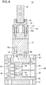
FIG. 4 is a cross-sectional view of the air chuck ofFIG. 2 taken along line IV-IV; -
FIG. 5 is a partially developed view of the air chuck ofFIG. 1 when viewed from a predetermined direction; -
FIG. 6 is a partially developed view of the air chuck ofFIG. 1 when viewed from a direction different from that ofFIG. 5 ; -
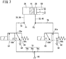
FIG. 7 is a fluid circuit diagram of the air chuck ofFIG. 1 when a chuck unit is connected to a valve unit at a first rotation position; -
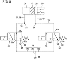
FIG. 8 is a fluid circuit diagram of the air chuck ofFIG. 1 when the chuck unit is connected to the valve unit at a second rotation position; -
FIG. 9 shows a state in which a waterproof cover is attached to the air chuck ofFIG. 1 ; and -
FIG. 10 is a view showing a change of a state in which the chuck unit is connected to the valve unit in the air chuck ofFIG. 1 . - In the following description, when terms in relation to upper and lower directions are used, for the sake of convenience, such terms refer to the directions shown in the drawings, however, the actual arrangement of the respective constituent members or the like is not limited thereby. An
air chuck 10 according to an embodiment of the present invention is formed of achuck unit 12 and avalve unit 56. - As shown in
FIGS. 1 and2 , thechuck unit 12 includes a rectangularparallelepiped cylinder body 14, a disk-shaped connector body 36, abase body 42, and a pair offingers 50 for gripping a workpiece. Theconnector body 36 is connected to the lower side of thecylinder body 14, and thebase body 42 is connected to the upper side of thecylinder body 14. - As shown in
FIG. 3 , thecylinder body 14 has acylinder hole 14a that opens at both ends, and apiston 16 is disposed in thecylinder hole 14a. Thepiston 16 includes amain body portion 16a sliding in thecylinder hole 14a, and arod portion 16b extending upward from themain body portion 16a. Arod cover 22 is attached to an upper end opening portion of thecylinder hole 14a, and acap 24 is attached to a lower end opening portion of thecylinder hole 14a. - A
first pressure chamber 26 is formed between themain body portion 16a of thepiston 16 and thecap 24, and asecond pressure chamber 28 is formed between themain body portion 16a of thepiston 16 and therod cover 22. Thecylinder body 14 includes a first pressure chamberair flow path 30 communicating with thefirst pressure chamber 26, and a second pressure chamberair flow path 32 communicating with thesecond pressure chamber 28. The first pressure chamberair flow path 30 and the second pressure chamberair flow path 32 open at a lower end of thecylinder body 14. - A wide side surface of the
cylinder body 14 is provided with twosensor grooves 14b extending from an upper end to a lower end of the cylinder body 14 (seeFIG. 5 ).Magnetic sensors 34 for detecting the magnetism ofmagnets 18 mounted on thepiston 16 are attached to therespective sensor grooves 14b. The position of thepiston 16 can be detected by themagnetic sensors 34.Lead wires 34a of themagnetic sensors 34 extend downward from thecylinder body 14. - A pair of L-
shaped levers 44 are disposed on thebase body 42. Each of thelevers 44 has afirst end portion 44a bifurcated by a cutout groove portion, and asecond end portion 44b formed in a spherical shape. Each of thelevers 44 is rotatably supported at its central portion by alever shaft 46 fixed to thebase body 42. Thefirst end portion 44a of thelever 44 engages with anengagement pin 20 attached to therod portion 16b of thepiston 16. - A
support member 48 that supports the pair offingers 50 is disposed on the upper side of thebase body 42. Thesupport member 48 is provided with a pair ofrail grooves 48a for guiding thefingers 50 such that thefingers 50 are movable in a direction orthogonal to the axis of thecylinder hole 14a. Thefingers 50 each have abase portion 50a disposed between the pair ofrail grooves 48a of thesupport member 48, and afinger portion 50b extending upward from thebase portion 50a. A plurality ofrolling elements 49 are arranged between thebase portion 50a of thefinger 50 and therail grooves 48a of thesupport member 48. Thesecond end portion 44b of thelever 44 engages with anengagement groove 50c provided in thebase portion 50a of thefinger 50.Reference symbol 55a denotes bolts for connecting thebase body 42 to thecylinder body 14.Reference symbol 55b denotes bolts for connecting thesupport member 48 to thebase body 42. - When air is supplied to the
first pressure chamber 26 and air is discharged from thesecond pressure chamber 28, thepiston 16 is driven upward. As a result, the pair oflevers 44 rotate in the direction in which thesecond end portions 44b separate from each other, and the pair offingers 50 move away from each other. When air is supplied to thesecond pressure chamber 28 and air is discharged from thefirst pressure chamber 26, thepiston 16 is driven downward. As a result, the pair oflevers 44 rotate in the direction in which thesecond end portions 44b approach each other, and the pair offingers 50 move toward each other. - A
first connection passage 38 and asecond connection passage 40 pass through theconnector body 36 in the up-down direction. Thefirst connection passage 38 is connected to the first pressure chamberair flow path 30 of thecylinder body 14, and thesecond connection passage 40 is connected to the second pressure chamberair flow path 32 of thecylinder body 14. A leadwire insertion hole 36a through which thelead wires 34a of themagnetic sensors 34 are inserted passes through theconnector body 36 in the up-down direction. - A
first bolt 52 is inserted through a firstbolt insertion hole 36b of theconnector body 36 and is screwed into ascrew hole 14c of the bottom portion of thecylinder body 14. As a result, theconnector body 36 is connected to the cylinder body 14 (seeFIG. 4 ).Reference symbols connector body 36 is connected to thecylinder body 14. - As shown in
FIG. 5 , theconnector body 36 includes four secondbolt insertion holes 36c at positions close to the outer periphery thereof. The secondbolt insertion holes 36c are arranged at intervals of 90 degrees around a central axis CL of theconnector body 36. The secondbolt insertion holes 36c are not covered by thecylinder body 14 in a state where theconnector body 36 is connected to thecylinder body 14. - As shown in
FIGS. 5 and6 , thevalve unit 56 includes a valve unitmain body 62 to which afirst solenoid valve 58 and asecond solenoid valve 60 are attached, and a disk-shapedadapter 92 connected to the lower side of the valve unitmain body 62. The valve unitmain body 62 includes a cylindricalouter wall portion 64, a flowpath block portion 70 inside theouter wall portion 64, anupper plate portion 88, and alower plate portion 90 on the lower side of the flowpath block portion 70. Theupper plate portion 88 crosses the flowpath block portion 70 inside theouter wall portion 64. Theadapter 92 is a member to be attached to the robot arm or the like (not shown). - The
outer wall portion 64 has a rectangularfirst opening 64a. Theouter wall portion 64 has asecond opening 64b at a position on an opposite side to thefirst opening 64a with respect to a central axis CL of the valve unit 56 (which is the same as the central axis CL of the connector body 36). The flowpath block portion 70 includes a flat solenoid valvejoint surface 72 facing thefirst opening 64a. Thefirst solenoid valve 58 and thesecond solenoid valve 60 are attached to the solenoid valvejoint surface 72, and are attachable and detachable through thefirst opening 64a. - The flow
path block portion 70 includes a first outputair flow path 74 and a second outputair flow path 76. One end of the first outputair flow path 74 opens to an upper surface of the flowpath block portion 70, and the other end thereof opens to the solenoid valvejoint surface 72. Similarly, one end of the second outputair flow path 76 opens to the upper surface of the flowpath block portion 70, and the other end thereof opens to the solenoid valvejoint surface 72. InFIG. 5 , openings of the first outputair flow path 74 and the second outputair flow path 76 in the solenoid valvejoint surface 72 are omitted.Reference numeral 73 denotes screw holes for attaching thefirst solenoid valve 58 and thesecond solenoid valve 60. - As will be described later, one end of the first output
air flow path 74 is connected to one of thefirst connection passage 38 or thesecond connection passage 40 of theconnector body 36. Further, one end of the second outputair flow path 76 is connected to the other of thefirst connection passage 38 and thesecond connection passage 40 of theconnector body 36.FIG. 3 shows a state where the first outputair flow path 74 is connected to thefirst connection passage 38 and the second outputair flow path 76 is connected to thesecond connection passage 40. - Further, the flow
path block portion 70 includes a supplyair flow path 78 including acommon flow path 78a, a firstbranch flow path 78b, and a secondbranch flow path 78c (seeFIG. 7 ). One end of thecommon flow path 78a opens to a side surface of the flowpath block portion 70 located on the opposite side of the solenoid valvejoint surface 72. Asupply port 66 is attached to the opening (seeFIG. 6 ). The firstbranch flow path 78b and the secondbranch flow path 78c branch from thecommon flow path 78a, and open to the solenoid valvejoint surface 72. Air is supplied to thesupply port 66 from an air supply source (not shown). InFIG. 5 , openings of the firstbranch flow path 78b and the secondbranch flow path 78c in the solenoid valvejoint surface 72 are omitted. - The flow
path block portion 70 further includes a first dischargeair flow path 80 and a second dischargeair flow path 82. One end of the first dischargeair flow path 80 opens to the solenoid valvejoint surface 72, and the other end thereof opens to a side surface of the flowpath block portion 70 at a position facing thesecond opening 64b. Similarly, one end of the second dischargeair flow path 82 opens to the solenoid valvejoint surface 72, and the other end thereof opens to the side surface of the flowpath block portion 70 at a position facing thesecond opening 64b. Afirst exhaust port 84 provided with a variable throttle valve is connected to the other end of the first dischargeair flow path 80, and asecond exhaust port 86 provided with a variable throttle valve is connected to the other end of the second discharge air flow path 82 (seeFIG. 4 ). InFIG. 5 , openings of the first dischargeair flow path 80 and the second dischargeair flow path 82 in the solenoid valvejoint surface 72 are omitted. - As shown in
FIG. 7 , thefirst solenoid valve 58 and thesecond solenoid valve 60 are configured as two-position three-port switching valves. Afirst port 58a of thefirst solenoid valve 58 is connected to the first outputair flow path 74. Asecond port 58b of thefirst solenoid valve 58 is connected to the firstbranch flow path 78b of the supplyair flow path 78. Athird port 58c of thefirst solenoid valve 58 is connected to the first dischargeair flow path 80. Afirst port 60a of thesecond solenoid valve 60 is connected to the second outputair flow path 76. Asecond port 60b of thesecond solenoid valve 60 is connected to the secondbranch flow path 78c of the supplyair flow path 78. Athird port 60c of thesecond solenoid valve 60 is connected to the second dischargeair flow path 82. - The
first solenoid valve 58 is configured such that thefirst port 58a is connected to thesecond port 58b when energized, and thefirst port 58a is connected to thethird port 58c when de-energized. That is, thefirst solenoid valve 58 is a normally closed solenoid valve that connects the first outputair flow path 74 to the air supply source when energized and opens the first outputair flow path 74 to the atmosphere when de-energized. - On the other hand, the
second solenoid valve 60 is configured such that thefirst port 60a is connected to thethird port 60c when energized, and thefirst port 60a is connected to thesecond port 60b when de-energized. That is, thesecond solenoid valve 60 is a normally open solenoid valve that opens the second outputair flow path 76 to the atmosphere when energized, and connects the second outputair flow path 76 to the air supply source when de-energized. - The
outer wall portion 64 includes anelectrical connector 68 at a position proximate to thesupply port 66. Alead wire 58d for supplying power to thefirst solenoid valve 58 and alead wire 60d for supplying power to thesecond solenoid valve 60 are connected to theelectrical connector 68. Further, thelead wires 34a of themagnetic sensors 34 extending downward from anopening 88a of theupper plate portion 88 are also connected to theelectrical connector 68.Reference numeral 95 denotes bolts for connecting theadapter 92 to the valve unitmain body 62. - As shown in
FIG. 9 , a cylindricalwaterproof cover 98 that covers thefirst opening 64a is attached to the cylindricalouter wall portion 64 of the valve unitmain body 62. Thewaterproof cover 98 protects thefirst solenoid valve 58, thesecond solenoid valve 60, and the like. Note that thewaterproof cover 98 includes anopening 98a for not covering thefirst exhaust port 84 and thesecond exhaust port 86. - As shown in
FIG. 5 , theupper plate portion 88 of the valve unitmain body 62 includes four secondbolt mounting holes 88b at positions close to theouter wall portion 64. The secondbolt mounting holes 88b are arranged at intervals of 90 degrees around the central axis CL of thevalve unit 56. Thesecond bolts 54 are inserted into the secondbolt insertion holes 36c of theconnector body 36 of thechuck unit 12 from the upper side of theconnector body 36, and are screwed into the secondbolt mounting holes 88b of theupper plate portion 88. Thus, theconnector body 36 is connected to the valve unitmain body 62. That is, thechuck unit 12 is connected to thevalve unit 56 by the foursecond bolts 54. - The
chuck unit 12 can be connected to thevalve unit 56 at two positions, the rotation angle of thechuck unit 12 around the central axis CL of thevalve unit 56 being different at the two positions by 180 degrees (seeFIG. 10 ). Hereinafter, these positions are referred to as a "first rotation position" and a "second rotation position". In the present embodiment, thechuck unit 12 is connected to thevalve unit 56 by the foursecond bolts 54 arranged at intervals of 90 degrees. However, other connecting elements may be used as long as thechuck unit 12 can be connected to thevalve unit 56 at positions where the rotation angle of thechuck unit 12 is different by 180 degrees.Reference symbols connector body 36 is connected to the valve unitmain body 62. - At the first rotation position, the first output
air flow path 74 of the flowpath block portion 70 of the valve unitmain body 62 is connected to thefirst connection passage 38 of theconnector body 36 of thechuck unit 12. Further, the second outputair flow path 76 of the flowpath block portion 70 of the valve unitmain body 62 is connected to thesecond connection passage 40 of theconnector body 36 of the chuck unit 12 (seeFIG. 7 ). On the other hand, at the second rotation position, the first outputair flow path 74 of the flowpath block portion 70 of the valve unitmain body 62 is connected to thesecond connection passage 40 of theconnector body 36 of thechuck unit 12. Further, the second outputair flow path 76 of the flowpath block portion 70 of the valve unitmain body 62 is connected to thefirst connection passage 38 of theconnector body 36 of the chuck unit 12 (seeFIG. 8 ). - The operation of the
air chuck 10 when thechuck unit 12 is connected to thevalve unit 56 at the first rotation position will be described with reference toFIG. 7 . The fluid circuit diagram ofFIG. 7 shows a state in which thefirst solenoid valve 58 and thesecond solenoid valve 60 are not energized. InFIG. 7 , reference symbol P1 indicates a connection point between the first outputair flow path 74 and thefirst connection passage 38, and reference symbol P2 indicates a connection point between the second outputair flow path 76 and thesecond connection passage 40. - When the pair of
fingers 50 are urged to separate from each other, thefirst solenoid valve 58 and thesecond solenoid valve 60 are energized. When thefirst solenoid valve 58 is energized, air from thesupply port 66 passes through the supplyair flow path 78 of the flowpath block portion 70 and reaches thesecond port 58b of thefirst solenoid valve 58. Thereafter, the air passes through the first outputair flow path 74 of the flowpath block portion 70 from thefirst port 58a of thefirst solenoid valve 58, further passes through thefirst connection passage 38 of theconnector body 36 and the first pressure chamberair flow path 30 of thecylinder body 14, and is supplied to thefirst pressure chamber 26. - Further, when the
second solenoid valve 60 is energized, air in thesecond pressure chamber 28 passes through the second pressure chamberair flow path 32 of thecylinder body 14, thesecond connection passage 40 of theconnector body 36, and the second outputair flow path 76 of the flowpath block portion 70, and reaches thefirst port 60a of thesecond solenoid valve 60. Thereafter, the air passes through the second dischargeair flow path 82 from thethird port 60c of thesecond solenoid valve 60, and is exhausted from thesecond exhaust port 86. In this manner, since air is supplied to thefirst pressure chamber 26 and the air in thesecond pressure chamber 28 is exhausted, the pair offingers 50 are driven to separate from each other. Since thesecond exhaust port 86 is provided with the variable throttle valve, the speed at which the pair offingers 50 move away from each other can be adjusted. - When the pair of
fingers 50 are urged to approach each other, energization of thefirst solenoid valve 58 and thesecond solenoid valve 60 is stopped. By stopping the energization of thesecond solenoid valve 60, the air from thesupply port 66 passes through the supplyair flow path 78 of the flowpath block portion 70 and reaches thesecond port 60b of thesecond solenoid valve 60. Thereafter, the air passes through the second outputair flow path 76 of the flowpath block portion 70 from thefirst port 60a of thesecond solenoid valve 60. Further, the air passes through thesecond connection passage 40 of theconnector body 36 and the second pressure chamberair flow path 32 of thecylinder body 14, and is supplied to thesecond pressure chamber 28. - Further, by stopping the energization of the
first solenoid valve 58, the air in thefirst pressure chamber 26 passes through the first pressure chamberair flow path 30 of thecylinder body 14, thefirst connection passage 38 of theconnector body 36, and the first outputair flow path 74 of the flowpath block portion 70, and reaches thefirst port 58a of thefirst solenoid valve 58. Thereafter, the air passes through the first dischargeair flow path 80 from thethird port 58c of thefirst solenoid valve 58, and is exhausted from thefirst exhaust port 84. In this manner, since air is supplied to thesecond pressure chamber 28 and the air in thefirst pressure chamber 26 is exhausted, the pair offingers 50 are driven to approach each other. Since thefirst exhaust port 84 is provided with the variable throttle valve, the speed at which the pair offingers 50 move toward each other can be adjusted. - The
air chuck 10 is attached to the robot arm or the like (not shown) with thefingers 50 downward. When a workpiece is gripped in manner that the workpiece is sandwiched inside the pair offingers 50, as described above, thechuck unit 12 may be connected to thevalve unit 56 at the first rotation position. Since the pair offingers 50 are driven to approach each other at the time of de-energization due to power failure or the like, it is possible to prevent the workpiece from falling. - Next, the operation of the
air chuck 10 when thechuck unit 12 is connected to thevalve unit 56 at the second rotation position will be described with reference toFIG. 8 . The fluid circuit diagram ofFIG. 8 shows a state in which thefirst solenoid valve 58 and thesecond solenoid valve 60 are not energized. InFIG. 8 , reference symbol P3 indicates a connection point between the second outputair flow path 76 and thefirst connection passage 38, and reference symbol P4 indicates a connection point between the first outputair flow path 74 and thesecond connection passage 40. - When the pair of
fingers 50 are urged to separate from each other, energization of thefirst solenoid valve 58 and thesecond solenoid valve 60 is stopped. By stopping the energization of thesecond solenoid valve 60, the air from thesupply port 66 passes through the supplyair flow path 78 of the flowpath block portion 70 and reaches thesecond port 60b of thesecond solenoid valve 60. Thereafter, the air passes through the second outputair flow path 76 of the flowpath block portion 70 from thefirst port 60a of thesecond solenoid valve 60. Further, the air passes through thefirst connection passage 38 of theconnector body 36 and the first pressure chamberair flow path 30 of thecylinder body 14, and is supplied to thefirst pressure chamber 26. - Further, by stopping the energization of the
first solenoid valve 58, the air in thesecond pressure chamber 28 passes through the second pressure chamberair flow path 32 of thecylinder body 14, thesecond connection passage 40 of theconnector body 36, and the first outputair flow path 74 of the flowpath block portion 70, and reaches thefirst port 58a of thefirst solenoid valve 58. Thereafter, the air passes through the first dischargeair flow path 80 from thethird port 58c of thefirst solenoid valve 58, and is exhausted from thefirst exhaust port 84. In this manner, since air is supplied to thefirst pressure chamber 26 and the air in thesecond pressure chamber 28 is exhausted, the pair offingers 50 are driven to separate from each other. Since thefirst exhaust port 84 is provided with the variable throttle valve, the speed at which the pair offingers 50 move away from each other can be adjusted. - When the pair of
fingers 50 are urged to approach each other, thefirst solenoid valve 58 and thesecond solenoid valve 60 are energized. By energizing thefirst solenoid valve 58, air from thesupply port 66 passes through the supplyair flow path 78 of the flowpath block portion 70 and reaches thesecond port 58b of thefirst solenoid valve 58. Thereafter, the air passes through the first outputair flow path 74 of the flowpath block portion 70 from thefirst port 58a of thefirst solenoid valve 58. Further, the air passes through thesecond connection passage 40 of theconnector body 36 and the second pressure chamberair flow path 32 of thecylinder body 14, and is supplied to thesecond pressure chamber 28. - Further by energizing the
second solenoid valve 60, air in thefirst pressure chamber 26 passes through the first pressure chamberair flow path 30 of thecylinder body 14, thefirst connection passage 38 of theconnector body 36, and the second outputair flow path 76 of the flowpath block portion 70, and reaches thefirst port 60a of thesecond solenoid valve 60. Thereafter, the air passes through the second dischargeair flow path 82 from thethird port 60c of thesecond solenoid valve 60, and is exhausted from thesecond exhaust port 86. In this manner, since air is supplied to thesecond pressure chamber 28 and the air in thefirst pressure chamber 26 is exhausted, the pair offingers 50 are driven to approach each other. Since thesecond exhaust port 86 is provided with the variable throttle valve, the speed at which the pair offingers 50 move toward each other can be adjusted. - The
air chuck 10 is attached to the robot arm or the like (not shown) with thefingers 50 downward. When the pair offingers 50 are moved away from each other to grip the workpiece on the outside thereof, as described above, thechuck unit 12 may be connected to thevalve unit 56 at the second rotation position. Since the pair offingers 50 are driven to separate from each other at the time of de-energization due to power failure or the like, it is possible to prevent the workpiece from falling. - According to the
air chuck 10 of the present embodiment, thefirst solenoid valve 58 and thesecond solenoid valve 60 are a combination of a normally closed solenoid valve and a normally open solenoid valve. Therefore, the workpiece can be prevented from falling when thefirst solenoid valve 58 and thesecond solenoid valve 60 are de-energized due to a power failure or the like. Further, thechuck unit 12 can be selectively connected to thevalve unit 56 at the first rotation position or the second rotation position, the rotation angle of thechuck unit 12 around the central axis CL of thevalve unit 56 at the first rotation position being different from that at the second rotation position. For this reason, since the connection relationship between thefirst solenoid valve 58 and thesecond solenoid valve 60, and thefirst pressure chamber 26 and thesecond pressure chamber 28, can be switched, it is possible to easily realize the prevention of falling of the workpiece according to the gripping form of the workpiece. - In the present embodiment, the
air chuck 10 is configured to include a pair of fingers 50 (two fingers 50). However, for example, three or more fingers may be provided as in a case where a plurality of fingers are arranged at equal angles on a single circumference when viewed from a predetermined direction.
Claims (7)
- An air chuck (10) comprising:a chuck unit (12) including a plurality of fingers (50); anda valve unit (56) attached to a robot arm or a transport device, whereinthe chuck unit includes a first pressure chamber (26) and a second pressure chamber (28) disposed on both sides of a piston (16) configured to drive the plurality of fingers,the valve unit includes a first output air flow path (74) connected to one of the first pressure chamber or the second pressure chamber, a second output air flow path (76) connected to another one of the first pressure chamber or the second pressure chamber, a first solenoid valve (58) connected to the first output air flow path, and a second solenoid valve (60) connected to the second output air flow path,the first solenoid valve connects the first output air flow path to an air supply source when energized and opens the first output air flow path to atmosphere when de-energized, andthe second solenoid valve opens the second output air flow path to the atmosphere when energized and connects the second output air flow path to the air supply source when de-energized.
- The air chuck according to claim 1, whereinthe chuck unit is configured to be selectively connected to the valve unit at a first rotation position or a second rotation position, a rotation angle of the chuck unit around a central axis of the valve unit at the first rotation position being different from the rotation angle of the chuck unit around the central axis of the valve unit at the second rotation position,the first output air flow path is connected to the first pressure chamber and the second output air flow path is connected to the second pressure chamber at the first rotation position, andthe first output air flow path is connected to the second pressure chamber and the second output air flow path is connected to the first pressure chamber at the second rotation position.
- The air chuck according to claim 2, whereinthe valve unit includes a single supply port (66), a first exhaust port (84) provided with a variable throttle valve, and a second exhaust port (86) provided with a variable throttle valve,the supply port is connected to the first solenoid valve and the second solenoid valve via a predetermined flow path,the first exhaust port is connected to the first solenoid valve via a predetermined flow path, andthe second exhaust port is connected to the second solenoid valve via a predetermined flow path.
- The air chuck according to claim 2, whereinthe valve unit includes a valve unit main body (62) including an outer wall portion (64) having a cylindrical shape, andthe chuck unit includes a connector body (36) having a disk shape and connected to the valve unit main body.
- The air chuck according to claim 4, whereinthe first solenoid valve and the second solenoid valve are attached to the valve unit main body, andthe outer wall portion of the valve unit main body includes an opening (64a) configured to allow attachment and detachment of the first solenoid valve and the second solenoid valve.
- The air chuck according to claim 5, wherein
a waterproof cover (98) having a cylindrical shape and configured to cover the opening is attached to the valve unit main body. - The air chuck according to claim 4, whereinthe chuck unit includes a magnetic sensor (34) configured to detect a position of the piston, andthe outer wall portion of the valve unit main body is provided with an electrical connector (68) to which a lead wire (34a) of the magnetic sensor, a lead wire (58d) of the first solenoid valve, and a lead wire (60d) of the second solenoid valve are connected.
Applications Claiming Priority (1)
| Application Number | Priority Date | Filing Date | Title |
|---|---|---|---|
| JP2021067506A JP7625951B2 (en) | 2021-04-13 | 2021-04-13 | Air chuck |
Publications (2)
| Publication Number | Publication Date |
|---|---|
| EP4074468A1 true EP4074468A1 (en) | 2022-10-19 |
| EP4074468B1 EP4074468B1 (en) | 2026-01-28 |
Family
ID=81325724
Family Applications (1)
| Application Number | Title | Priority Date | Filing Date |
|---|---|---|---|
| EP22167071.4A Active EP4074468B1 (en) | 2021-04-13 | 2022-04-07 | Air chuck |
Country Status (5)
| Country | Link |
|---|---|
| US (1) | US12564971B2 (en) |
| EP (1) | EP4074468B1 (en) |
| JP (1) | JP7625951B2 (en) |
| KR (1) | KR20220141751A (en) |
| CN (1) | CN115194803A (en) |
Families Citing this family (2)
| Publication number | Priority date | Publication date | Assignee | Title |
|---|---|---|---|---|
| CA3162295A1 (en) * | 2021-06-18 | 2022-12-18 | Techjig Inc. | Robotic cell and method of operating same |
| JP2025163786A (en) * | 2024-04-18 | 2025-10-30 | Smc株式会社 | Chuck device and chuck system |
Citations (8)
| Publication number | Priority date | Publication date | Assignee | Title |
|---|---|---|---|---|
| US5944326A (en) * | 1997-02-12 | 1999-08-31 | Smc Corporation | Linear guide air chuck |
| US20080023925A1 (en) * | 2006-07-31 | 2008-01-31 | Smc Kabushiki Kaisha | Chuck Apparatus |
| JP2010149224A (en) | 2008-12-25 | 2010-07-08 | Idec Corp | Robot hand |
| JP2016155199A (en) * | 2015-02-25 | 2016-09-01 | Ckd株式会社 | Gripping device |
| US20170001245A1 (en) * | 2015-06-30 | 2017-01-05 | Smc Corporation | Chuck apparatus |
| DE102017109291A1 (en) * | 2016-04-28 | 2017-11-16 | Karsten Weiß | gripper module |
| US20200130069A1 (en) * | 2017-05-17 | 2020-04-30 | Smc Corporation | Air chuck provided with locking mechanism |
| US20200376568A1 (en) * | 2019-05-27 | 2020-12-03 | Smc Corporation | Drive system and control method for chuck device |
Family Cites Families (14)
| Publication number | Priority date | Publication date | Assignee | Title |
|---|---|---|---|---|
| JPS5990594U (en) * | 1982-12-06 | 1984-06-19 | フアナツク株式会社 | industrial robot hand |
| US4741568A (en) * | 1986-04-16 | 1988-05-03 | Robohand Inc. | Method and means for limiting the extent of release travel of piston-operated grippers |
| US4913481A (en) * | 1988-09-13 | 1990-04-03 | Applied Power Inc. | Clean room gripper |
| JP2532171B2 (en) * | 1991-01-16 | 1996-09-11 | 倉敷紡績株式会社 | Selective object lifting device, test tube lifting device and control method thereof |
| US5595413A (en) * | 1994-12-12 | 1997-01-21 | Numation, Inc. | Fluid actuated gripper |
| JPH10138017A (en) * | 1996-09-16 | 1998-05-26 | Howa Mach Ltd | Chuck for chuck exchange and chuck exchange device |
| US6393694B2 (en) * | 1999-04-23 | 2002-05-28 | Koninklijke Philips Electronics N.V. | Gripping device |
| JP2000343473A (en) * | 1999-06-03 | 2000-12-12 | Smc Corp | Parallel opening/closing chuck |
| ATE268249T1 (en) * | 2002-04-05 | 2004-06-15 | Festo Ag & Co | FLUID ACTUATED GRIPPER |
| JP4538355B2 (en) * | 2005-03-28 | 2010-09-08 | 株式会社妙徳 | Suction nozzle device |
| JP5379457B2 (en) * | 2008-11-27 | 2013-12-25 | Idec株式会社 | Robot hand |
| JP2014091185A (en) * | 2012-11-01 | 2014-05-19 | Citizen Holdings Co Ltd | Chuck device and machine tool equipped with the chuck device |
| CN108136597B (en) * | 2015-09-29 | 2021-04-30 | 株式会社富士 | Component chuck device and component assembling device |
| DE102016011761A1 (en) * | 2016-10-04 | 2018-04-05 | Günther Zimmer | Gripping device with switching module |
-
2021
- 2021-04-13 JP JP2021067506A patent/JP7625951B2/en active Active
-
2022
- 2022-04-05 US US17/657,982 patent/US12564971B2/en active Active
- 2022-04-07 KR KR1020220043284A patent/KR20220141751A/en active Pending
- 2022-04-07 EP EP22167071.4A patent/EP4074468B1/en active Active
- 2022-04-12 CN CN202210379078.3A patent/CN115194803A/en active Pending
Patent Citations (8)
| Publication number | Priority date | Publication date | Assignee | Title |
|---|---|---|---|---|
| US5944326A (en) * | 1997-02-12 | 1999-08-31 | Smc Corporation | Linear guide air chuck |
| US20080023925A1 (en) * | 2006-07-31 | 2008-01-31 | Smc Kabushiki Kaisha | Chuck Apparatus |
| JP2010149224A (en) | 2008-12-25 | 2010-07-08 | Idec Corp | Robot hand |
| JP2016155199A (en) * | 2015-02-25 | 2016-09-01 | Ckd株式会社 | Gripping device |
| US20170001245A1 (en) * | 2015-06-30 | 2017-01-05 | Smc Corporation | Chuck apparatus |
| DE102017109291A1 (en) * | 2016-04-28 | 2017-11-16 | Karsten Weiß | gripper module |
| US20200130069A1 (en) * | 2017-05-17 | 2020-04-30 | Smc Corporation | Air chuck provided with locking mechanism |
| US20200376568A1 (en) * | 2019-05-27 | 2020-12-03 | Smc Corporation | Drive system and control method for chuck device |
Also Published As
| Publication number | Publication date |
|---|---|
| CN115194803A (en) | 2022-10-18 |
| US20220324120A1 (en) | 2022-10-13 |
| KR20220141751A (en) | 2022-10-20 |
| TW202246029A (en) | 2022-12-01 |
| US12564971B2 (en) | 2026-03-03 |
| JP7625951B2 (en) | 2025-02-04 |
| JP2022162616A (en) | 2022-10-25 |
| EP4074468B1 (en) | 2026-01-28 |
Similar Documents
| Publication | Publication Date | Title |
|---|---|---|
| EP4074468B1 (en) | Air chuck | |
| US6505642B2 (en) | Manifold valve having position detecting function | |
| JP7333309B2 (en) | Magnetic coupling device with at least one of sensor configuration and demagnetization | |
| US20020026959A1 (en) | Manifold valve having position detecting function | |
| US10780575B2 (en) | Robot end effector cuff | |
| CN110370261B (en) | Rotational drive device and robot arm of a robot equipped with the same | |
| EP1195528B1 (en) | Selector valve with magnetometric sensor | |
| KR102755604B1 (en) | Rotary drive device and robot arm of a robot equipped therewith | |
| CN109906133B (en) | Clamping device with switch module | |
| KR20200136324A (en) | Drive system and control method for chuck device | |
| US12202130B2 (en) | Seal affixing system | |
| KR840001146B1 (en) | Wrist mechanism of industrial robots | |
| US4530636A (en) | Device for operating a hand of an industrial robot | |
| CN100409990C (en) | control device | |
| TWI916546B (en) | Air chuck | |
| KR20190120078A (en) | Rotary drive device and robot arm of a robot equipped therewith | |
| JP5379457B2 (en) | Robot hand | |
| US5810034A (en) | Balanced rotary air manifold | |
| CN220316525U (en) | Air source device and rotor | |
| KR200387444Y1 (en) | Swivel head | |
| KR102628174B1 (en) | Negative pressure generating structure and actuator | |
| WO2025154101A1 (en) | A device and method for providing integrated pneumatic and vacuum tooling | |
| US20220381264A1 (en) | A Valve Manifold, Valve and Actuator Assembly | |
| JPH0932804A (en) | Rotary actuator | |
| JP2003156158A (en) | Rotary actuator |
Legal Events
| Date | Code | Title | Description |
|---|---|---|---|
| PUAI | Public reference made under article 153(3) epc to a published international application that has entered the european phase |
Free format text: ORIGINAL CODE: 0009012 |
|
| STAA | Information on the status of an ep patent application or granted ep patent |
Free format text: STATUS: THE APPLICATION HAS BEEN PUBLISHED |
|
| AK | Designated contracting states |
Kind code of ref document: A1 Designated state(s): AL AT BE BG CH CY CZ DE DK EE ES FI FR GB GR HR HU IE IS IT LI LT LU LV MC MK MT NL NO PL PT RO RS SE SI SK SM TR |
|
| STAA | Information on the status of an ep patent application or granted ep patent |
Free format text: STATUS: REQUEST FOR EXAMINATION WAS MADE |
|
| 17P | Request for examination filed |
Effective date: 20230405 |
|
| RBV | Designated contracting states (corrected) |
Designated state(s): AL AT BE BG CH CY CZ DE DK EE ES FI FR GB GR HR HU IE IS IT LI LT LU LV MC MK MT NL NO PL PT RO RS SE SI SK SM TR |
|
| STAA | Information on the status of an ep patent application or granted ep patent |
Free format text: STATUS: EXAMINATION IS IN PROGRESS |
|
| 17Q | First examination report despatched |
Effective date: 20240806 |
|
| RAP3 | Party data changed (applicant data changed or rights of an application transferred) |
Owner name: SMC CORPORATION |
|
| GRAP | Despatch of communication of intention to grant a patent |
Free format text: ORIGINAL CODE: EPIDOSNIGR1 |
|
| STAA | Information on the status of an ep patent application or granted ep patent |
Free format text: STATUS: GRANT OF PATENT IS INTENDED |
|
| INTG | Intention to grant announced |
Effective date: 20250909 |
|
| GRAS | Grant fee paid |
Free format text: ORIGINAL CODE: EPIDOSNIGR3 |
|
| GRAA | (expected) grant |
Free format text: ORIGINAL CODE: 0009210 |
|
| STAA | Information on the status of an ep patent application or granted ep patent |
Free format text: STATUS: THE PATENT HAS BEEN GRANTED |
|
| AK | Designated contracting states |
Kind code of ref document: B1 Designated state(s): AL AT BE BG CH CY CZ DE DK EE ES FI FR GB GR HR HU IE IS IT LI LT LU LV MC MK MT NL NO PL PT RO RS SE SI SK SM TR |
|
| REG | Reference to a national code |
Ref country code: CH Ref legal event code: F10 Free format text: ST27 STATUS EVENT CODE: U-0-0-F10-F00 (AS PROVIDED BY THE NATIONAL OFFICE) Effective date: 20260128 Ref country code: GB Ref legal event code: FG4D |
|
| REG | Reference to a national code |
Ref country code: DE Ref legal event code: R096 Ref document number: 602022029065 Country of ref document: DE |
|
| REG | Reference to a national code |
Ref country code: IE Ref legal event code: FG4D |