EP4074466A1 - Position detection method, control device, and robot system - Google Patents
Position detection method, control device, and robot system Download PDFInfo
- Publication number
- EP4074466A1 EP4074466A1 EP20899638.9A EP20899638A EP4074466A1 EP 4074466 A1 EP4074466 A1 EP 4074466A1 EP 20899638 A EP20899638 A EP 20899638A EP 4074466 A1 EP4074466 A1 EP 4074466A1
- Authority
- EP
- European Patent Office
- Prior art keywords
- robot
- detection
- relation
- contacting structure
- controller
- Prior art date
- Legal status (The legal status is an assumption and is not a legal conclusion. Google has not performed a legal analysis and makes no representation as to the accuracy of the status listed.)
- Pending
Links
Images





Classifications
-
- B—PERFORMING OPERATIONS; TRANSPORTING
- B25—HAND TOOLS; PORTABLE POWER-DRIVEN TOOLS; MANIPULATORS
- B25J—MANIPULATORS; CHAMBERS PROVIDED WITH MANIPULATION DEVICES
- B25J9/00—Program-controlled manipulators
- B25J9/16—Program controls
- B25J9/1679—Program controls characterised by the tasks executed
- B25J9/1682—Dual arm manipulator; Coordination of several manipulators
-
- B—PERFORMING OPERATIONS; TRANSPORTING
- B25—HAND TOOLS; PORTABLE POWER-DRIVEN TOOLS; MANIPULATORS
- B25J—MANIPULATORS; CHAMBERS PROVIDED WITH MANIPULATION DEVICES
- B25J9/00—Program-controlled manipulators
- B25J9/10—Program-controlled manipulators characterised by positioning means for manipulator elements
-
- B—PERFORMING OPERATIONS; TRANSPORTING
- B25—HAND TOOLS; PORTABLE POWER-DRIVEN TOOLS; MANIPULATORS
- B25J—MANIPULATORS; CHAMBERS PROVIDED WITH MANIPULATION DEVICES
- B25J9/00—Program-controlled manipulators
- B25J9/06—Program-controlled manipulators characterised by multi-articulated arms
-
- B—PERFORMING OPERATIONS; TRANSPORTING
- B25—HAND TOOLS; PORTABLE POWER-DRIVEN TOOLS; MANIPULATORS
- B25J—MANIPULATORS; CHAMBERS PROVIDED WITH MANIPULATION DEVICES
- B25J9/00—Program-controlled manipulators
- B25J9/16—Program controls
- B25J9/1628—Program controls characterised by the control loop
- B25J9/1633—Program controls characterised by the control loop compliant, force, torque control, e.g. combined with position control
-
- B—PERFORMING OPERATIONS; TRANSPORTING
- B25—HAND TOOLS; PORTABLE POWER-DRIVEN TOOLS; MANIPULATORS
- B25J—MANIPULATORS; CHAMBERS PROVIDED WITH MANIPULATION DEVICES
- B25J9/00—Program-controlled manipulators
- B25J9/16—Program controls
- B25J9/1628—Program controls characterised by the control loop
- B25J9/1653—Program controls characterised by the control loop parameters identification, estimation, stiffness, accuracy, error analysis
-
- B—PERFORMING OPERATIONS; TRANSPORTING
- B25—HAND TOOLS; PORTABLE POWER-DRIVEN TOOLS; MANIPULATORS
- B25J—MANIPULATORS; CHAMBERS PROVIDED WITH MANIPULATION DEVICES
- B25J9/00—Program-controlled manipulators
- B25J9/16—Program controls
- B25J9/1694—Program controls characterised by use of sensors other than normal servo-feedback from position, speed or acceleration sensors, perception control, multi-sensor controlled systems, sensor fusion
- B25J9/1697—Vision controlled systems
-
- G—PHYSICS
- G05—CONTROLLING; REGULATING
- G05B—CONTROL OR REGULATING SYSTEMS IN GENERAL; FUNCTIONAL ELEMENTS OF SUCH SYSTEMS; MONITORING OR TESTING ARRANGEMENTS FOR SUCH SYSTEMS OR ELEMENTS
- G05B2219/00—Program-control systems
- G05B2219/30—Nc systems
- G05B2219/39—Robotics, robotics to robotics hand
- G05B2219/39102—Manipulator cooperating with conveyor
-
- G—PHYSICS
- G05—CONTROLLING; REGULATING
- G05B—CONTROL OR REGULATING SYSTEMS IN GENERAL; FUNCTIONAL ELEMENTS OF SUCH SYSTEMS; MONITORING OR TESTING ARRANGEMENTS FOR SUCH SYSTEMS OR ELEMENTS
- G05B2219/00—Program-control systems
- G05B2219/30—Nc systems
- G05B2219/40—Robotics, robotics mapping to robotics vision
- G05B2219/40625—Tactile sensor
Definitions
- the present disclosure relates to a position detection method, a controller, and a robot system.
- Patent Literature 1 discloses a method of teaching a robot a position within a work environment by using a tactile sensor.
- the robot includes an arm with an end effector.
- the end effector includes a tactile sensor device including a touch sensitive surface.
- the robot brings the touch sensitive surface into contact with a work object, and the tactile sensor device generates a signal indicating the position of the contact with respect to the touch sensitive surface. Further, by using information including the generated signal, the position of the contact in the work environment is taught to the robot.
- the tactile sensor device including the touch sensitive surface is used to detect a positional relationship between the robot and the work object.
- a high-precision tactile sensor device is necessary, which causes increase in cost and increase in complexity of equipment.
- the robot with the tactile sensor device mounted thereto performs work, it may cause deterioration in the precision of the tactile sensor device, and consequently, calibration may become necessary, which complicates the work for the detection.
- An objective of the present disclosure is to provide a position detection method, a controller, and a robot system that simplify the detection of a positional relationship between a robot and a target object.
- a position detection method is a position detection method of detecting a position of a robot in relation to a target object, the robot including an arm.
- the method includes: (a) causing the arm, on which a contacting structure is disposed, to position the contacting structure laterally in a horizontal direction in relation to a first detection subject that is one of at least two detection subjects disposed on the target object; (b) causing the arm to move the contacting structure laterally to bring the contacting structure into contact with at least three locations on a surface of the first detection subject; (c) detecting positions of the contacting structure in relation to the robot when the contacting structure comes into contact with the at least three locations, respectively; (d) detecting a position of the first detection subject in relation to the robot by using the detected at least three positions of the contacting structure; (e) performing same steps as the steps (a) to (d) for another detection subject, different from the first detection subject, of the at least two detection subjects; and (f)
- the technique of the present disclosure makes it possible to simplify the detection of a positional relationship between the robot and the target object.
- a position detection method is a position detection method of detecting a position of a robot in relation to a target object, the robot including an arm.
- the method includes: (a) causing the arm, on which a contacting structure is disposed, to position the contacting structure laterally in a horizontal direction in relation to a first detection subject that is one of at least two detection subjects disposed on the target object; (b) causing the arm to move the contacting structure laterally to bring the contacting structure into contact with at least three locations on a surface of the first detection subject; (c) detecting positions of the contacting structure in relation to the robot when the contacting structure comes into contact with the at least three locations, respectively; (d) detecting a position of the first detection subject in relation to the robot by using the detected at least three positions of the contacting structure; (e) performing same steps as the steps (a) to (d) for another detection subject, different from the first detection subject, of the at least two detection subjects; and
- the positions of the contacting structure in relation to the robot when the contacting structure comes into contact with the at least three locations on the detection subject, respectively, are detected, and thereby the position of each detection subject in relation to the robot is detected. Further, the position of the robot in relation to the target object is detected by using the position of each detection subject in relation to the robot.
- the position detection as above can be realized by disposing the contacting structure on the arm of the robot and through the above-described operations by the robot. Therefore, the detection of the positional relationship between the robot and the target object is simplified.
- each of the at least two detection subjects may be one of a recess or a projection, the projection being insertable in the recess.
- the contacting structure may be the other of the recess or the projection.
- the method may include, in the step (a), positioning the contacting structure laterally in relation to the first detection subject by moving the contacting structure such that the projection is inserted in the recess.
- the contacting structure in the step (b), the contacting structure is moved laterally in a state where the projection is inserted in the recess. The range of movement of the contacting structure is restricted by the recess. Consequently, an arm operation for bringing the contacting structure and the detection subject into contact with each other is made simple and fast.
- the method may include, in the step (f), detecting the position and an orientation of the robot in relation to the target object. According to this aspect, the detection of a precise positional relationship between the robot and the target object is simplified.
- the arm may include at least two joints.
- the method may include, in the step (b), at each of the at least three locations, performing a first operation of operating a first joint, which is one of the at least two joints, to bring the contacting structure into contact with the surface of the first detection subject, and then performing a second operation of operating a second joint, which is another one of the at least two joints, to bring the contacting structure into contact with the surface of the first detection subject.
- a first operation it is possible that due to a large moving amount of the contacting structure, the contacting structure collides against and bounces off the surface of the detection subject.
- the moving amount of the contacting structure can be made small, and therefore, the contacting structure can be kept in contact with the surface of the detection subject.
- the contacting structure is brought into contact with the detection subject while the first joint or the second joint is operating, and thereby influence on the operations, the influence being caused by mechanical rattling (e.g., backlash) at the first joint and the second joint, is reduced. This makes it possible to detect a precise position of each part of the arm at the time of making a contact. Since the first joint and the second joint operate independently of each other, a moving amount of each joint until the contacting structure and the detection subject come into contact with each other can be readily detected.
- the first joint and the second joint may enable the arm to operate in a manner to move the contacting structure laterally.
- influence on the operation of the first joint the influence being caused by mechanical rattling (e.g., backlash) at the second joint
- influence on the operation of the second joint the influence being caused by mechanical rattling (e.g., backlash) at the first joint
- the method may include: in the first operation, lowering a gain of a second servomotor that drives the second joint than a gain of a first servomotor that drives the first j oint; and in the second operation, lowering the gain of the first servomotor than the gain of the second servomotor.
- influence on the operation of the first joint driven by the first servomotor the influence being caused by the driving force of the second servomotor for maintaining the state of the second joint
- influence on the operation of the second joint driven by the second servomotor the influence being caused by the driving force of the first servomotor for maintaining the state of the first joint
- the position detection method may further include: (g) causing the arm to perform an operation of indicating a type of control that is currently being performed among multiple types of control corresponding to respective target objects. According to this aspect, a user of the robot can visually recognize a process that is currently being performed by the robot.
- the position detection method may further include: (a1) causing the arm to position the contacting structure to a position above a peripheral surface around the first detection subject; (b1) causing the arm to lower the contacting structure to bring the contacting structure into contact with at least one location on the peripheral surface; (c1) detecting a height position of the contacting structure when the contacting structure comes into contact with each of the at least one location, the height position being a position of the contacting structure in a height direction in relation to the robot; (d1) detecting a height position of the first detection subject in relation to the robot by using the detected at least one height position of the contacting structure; and (e1) detecting a height position of the robot in relation to the target object by using the height position of the first detection subject in relation to the robot.
- the detection of the height position of the robot in relation to the target object can be realized by disposing the contacting structure on the arm of the robot and through the above-described operations by the robot.
- a controller is a controller for performing the position detection method according to the aspect of the present disclosure.
- the controller : performs the step (a) in accordance with manipulation information outputted from a manipulation input device with which to manipulate the robot, the manipulation input device receiving an input of a manipulation of the robot; and performs the steps (b) to (f) autonomously in accordance with a program.
- the controller can perform the steps (a) to (f) even if an approximate position of each detection subject in relation to the robot is unknown.
- a controller is a controller for performing the position detection method according to the aspect of the present disclosure.
- the controller may perform the steps (a) to (f) autonomously in accordance with a program.
- the controller can perform the steps (a) to (f) autonomously.
- a robot system includes: a controller that performs the position detection method according to the aspect of the present disclosure and controls an operation of the robot; and the robot. According to this aspect, the same advantageous effects as those of the controller according to the aspect of the present disclosure are obtained.
- the controller may: perform the step (a) in accordance with manipulation information outputted from a manipulation input device with which to manipulate the robot, the manipulation input device receiving an input of a manipulation of the robot; and perform the steps (b) to (f) autonomously in accordance with a program. According to this aspect, the same advantageous effects as those of the controller according to the aspect of the present disclosure are obtained.
- the controller may perform the steps (a) to (f) autonomously in accordance with a program. According to this aspect, the same advantageous effects as those of the controller according to the aspect of the present disclosure are obtained.
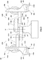
- FIG. 1 shows one example of the configuration of the robot system 1 according to the embodiment.
- the robot system 1 includes a robot 100, a manipulation input device 200, a controller 300, imaging devices 400, and a presentation device 500.
- the robot system 1 causes the robot 100 to autonomously perform two different types of work at different positions, respectively.
- the robot 100 packs articles WA conveyed by a belt conveyer 601A into a container box 603A on a placement table 602A, and places the container box 603A in which the articles WA have been packed onto another belt conveyer 604A, which conveys the container box 603A to another workplace.
- the robot 100 packs articles WB conveyed by a belt conveyer 601B into a container box 603B on a placement table 602B, and places the container box 603B in which the articles WB have been packed onto another belt conveyer 604B, which conveys the container box 603B to another workplace. It is necessary to move the robot 100 between the workplace WPA and the workplace WPB.
- the robot 100 Each time the robot 100 is moved, it is necessary to teach a position to the robot 100. Specifically, in the workplace WPA, it is necessary to store, in the controller 300, the positions of, for example, the robot 100 and the belt conveyer 601A relative to each other. In the workplace WPB, it is necessary to store, in the controller 300, the positions of, for example, the robot 100 and the belt conveyer 601B relative to each other.
- the controller 300 causes the robot 100 to autonomously perform predetermined work, such as packing work, in accordance with a program.
- the work performed by the robot 100 is not limited to the work illustratively described in the present embodiment, but may be any work.
- the controller 300 controls the operations of the robot 100 by autonomous control and manipulation control.
- the autonomous control causes the robot 100 to operate autonomously in accordance with a program.
- the manipulation control causes the robot 100 to operate in accordance with manipulation information corresponding to a manipulation that is inputted via the manipulation input device 200.
- FIG. 2 is a side view showing one example of the configuration of the robot 100 according to the embodiment.
- the robot 100 is an industrial robot as a non-limiting example.
- the robot 100 includes end effectors 110A and 110B, arms 120Aand 120B, a base 130, and inserts 140.
- the end effectors 110A and 110B perform actions on workpieces, such as the articles WA and WB.
- the arms 120A and 120B move the respective end effectors 110A and 110B so as to perform the actions.
- the arms 120A and 120B are robotic arms.
- the arms 120A and 120B are rotatably supported by the base 130.
- the base 130 is placed on a movable apparatus such as a transporter, and is thus movable.
- a transporter such as wheels and an AGV (Automated Guided Vehicle).
- the inserts 140 are disposed on the respective end effectors 110A and 110B. Specifically, the inserts 140 are disposed on the distal ends of the respective arms 120A and 120B, and are used in an operation of detecting the position of the robot 100.
- the arms 120A and 120B are not particularly limited, so long as the arms 120A and 120B are capable of moving the respective end effectors 110A and 110B disposed on their distal ends.
- the arms 120A and 120B are horizontal articulated arms.
- Each of the arms 120A and 120B may be, for example, a vertical articulated arm, a polar coordinate arm, a cylindrical coordinate arm, a Cartesian coordinate arm, or yet another type of robotic arm.
- the arms 120A and 120B are coaxially rotatable about a vertical first axis S1 in respective horizontal planes.
- the arm 120A is disposed to be shifted downward in the direction of the first axis S1 in relation to the arm 120B.
- the robot 100 is a coaxial dual-arm robot.
- the arm 120A includes links 121A to 124A, joints JA1 to JA4, and drivers DA1 to DA4.
- the arm 120B includes links 121B to 124B, joints JB1 to JB4, and drivers DB1 to DB4.
- the drivers DA1 to DA4 and DB1 to DB4 include, for example, electric motors using electricity as the source of power.
- the drivers DA1 to DA4 and DB1 to DB4 include servomotors.
- the drivers DA1 to DA4 and DB1 to DB4 are controlled by the controller 300 to drive the joints JA1 to JA4 and JB1 to JB4, respectively. Accordingly, the arms 120A and 120B operate independently of each other.
- the number of joints of each of the arms 120A and 120B is not limited to four, but may be five or more, or may be three or less.
- the links 121A and 121B are connected to the base 130 via the rotary joints JA1 and JB1, respectively, such that the links 121A and 121B are rotatable about the first axis S1 in respective horizontal planes.
- the links 122A and 122B are connected to the distal ends of the links 121A and 121B via the rotary joints JA2 and JB2, respectively, such that the links 122A and 122B are rotatable about respective vertical second axes S2a and S2b in respective horizontal planes.
- the links 123A and 123B are connected to the distal ends of the links 122A and 122B via the linear-motion joints JA3 and JB3, respectively, such that the links 123Aand 123B can be lifted and lowered along respective vertical third axes S3a and S3b.
- the links 124A and 124B are connected to the lower ends of the links 123A and 123B via the rotary joints JA4 and JB4, respectively, such that the links 124A and 124B are rotatable about respective longitudinal fourth axes S4a and S4b of the links 123A and 123B.
- the fourth axes S4a and S4b are vertical axes.
- Each of the links 124A and 124B includes a mechanical interface to connect to a corresponding one of the end effectors 110A and 110B.
- horizontal direction herein means, in a case where the robot 100 is disposed on a horizontal surface such as a horizontal floor surface, a horizontal direction parallel to the surface.
- vertical direction herein means, in the same case, a vertical direction perpendicular to the aforementioned surface.
- upward herein means, in the same case, a direction from the lower side toward the upper side.
- downward herein means, in the same case, a direction from the upper side toward the lower side.
- lateral or “laterally” herein means, in the same case, a direction extending along the aforementioned surface.
- FIG. 3 is a side view showing one example of the configuration of the end effector 110A according to the embodiment.
- the end effectors 110A and 110B are the same in configuration. Therefore, hereinafter, only the configuration of the end effector 110A is described, and the description of the configuration of the end effector 110B is omitted.
- the end effector 110A includes a connector 111, a support 112, a driver 113, and a gripper 114.
- the support 112 extends in a direction perpendicular the fourth axis S4a.
- the connector 111 is disposed on one end of the support 112 in its extending direction.
- the driver 113 is disposed on the other end of the support 112 in its extending direction.
- the connector 111 is connected to the mechanical interface of the link 124A via the insert 140.
- the driver 113 is mechanically connected to two gripping claws 114a of the gripper 114, and is capable of causing the gripping claws 114a to move toward each other and away from each other.
- Each gripping claw 114a extends in a direction crossing the fourth axis S4a. In the present embodiment, each gripping claw 114a extends in a direction perpendicular to the fourth axis S4a.
- the gripping claws 114a grip a workpiece such as an article WA or WB by moving toward each other, and stop gripping the workpiece by moving away from each other.
- the driver 113 includes, for example, an electric motor that uses electricity as the source of power.
- the driver 113 includes a servomotor.
- the driver 113 is controlled by the controller 300 to drive the gripping claws 114a.
- the insert 140 includes a shaft 141 and a connector 142.
- a single member serves as both the shaft 141 and the connector 142.
- the shaft 141 and the connector 142 may be dividable from each other.
- the connector 142 is connected to the mechanical interface of the link 124A.
- the connector 142 is disc-shaped and includes a circular surface similar to the surface of the mechanical interface.
- the connector 142 includes a protrusion 142a on the aforementioned circular surface.
- the protrusion 142a may be integrated with the connector 142, or may be attachable to and detachable from the connector 142.
- the protrusion 142a is an annular protrusion that has a planar shape similar to a planar shape of an annular groove 124Aa formed in the surface of the mechanical interface, and is fittable into the groove 124Aa.
- the connector 142 is positioned at a fixed position in relation to the surface of the mechanical interface as a result of the protrusion 142a being fitted into the groove 124Aa.
- the shape of each of the protrusion 142a and the groove 124Aa is not limited to an annular shape, so long as the positioning of the connector 142 can be performed by fitting the protrusion 142a to the groove 124Aa.
- the above-described protrusion and groove may be disposed on the link 124A and in the connector 142, respectively.
- the shaft 141 extends in a direction perpendicular to the circular surface of the connector 142 and extends downward opposite the protrusion 142a in a manner to penetrate the connector 111 and the support 112 of the end effector 110A.
- the shaft 141 projects downward from the support 112.
- the shaft 141 projects downward but not beyond the driver 113 and/or the gripper 114 of the end effector 110A.
- the connector 142 includes an annular groove 142b in its circular surface opposite the protrusion 142a.
- the connector 111 of the end effector 110A includes a protrusion 111a on its surface opposite the support 112.
- the protrusion 111a may be integrated with the connector 111, or may be attachable to and detachable from the connector 111.
- the protrusion 111a is an annular protrusion that has a planar shape similar to a planar shape of the groove 142b, and is fittable into the groove 142b.
- the connector 111 of the end effector 110A is positioned at a fixed position in relation to the insert 140 and the link 124A as a result of the protrusion 111a being fitted into the groove 142b.
- each of the protrusion 111a and the groove 142b is not limited to an annular shape, so long as the positioning of the connector 111 can be performed by fitting the protrusion 111a to the groove 142b.
- the above-described protrusion and groove may be disposed on the connector 142 and in the connector 111, respectively.
- the insert 140 as above is directly fixed to the link 124Ain a state where the connector 142 is sandwiched between the link 124A and the end effector 110A.
- the robot 100 can perform work in a state where the insert 140 is attached to the link 124A.
- the insert 140 may be directly fixed to the end effector 110A and indirectly fixed to the link 124A via the end effector 110A.
- the insert 140 is one example of a contacting structure, and is one example of a projection.
- the robot system 1 includes, in each of the workplace WPA and the workplace WPB, detection holes 150a (see FIG. 4 ), into each of which the shaft 141 of the insert 140 is inserted for detecting the position of the robot 100.
- the detection holes 150a extend in the vertical direction.
- members in which the respective detection holes 150a are formed are disposed at predetermined positions, respectively, in each of the workplace WPA and the workplace WPB.
- Each predetermined position may be a precisely known position or a precisely detectable position.
- FIG. 4 is a plan view showing one example of the members including the respective detection holes.
- jigs 150 with the respective detection holes 150a formed therein may be disposed on the belt conveyer 604A.
- each detection hole 150a has a cylindrical shape with a circular cross section.
- the detection hole 150a may have any shape, so long as at least three arbitrary locations on the inner wall surface of the detection hole 150a are detectable and by using the detected three locations, for example, a reference position such as the center or the center axis of the detection hole 150a, or the sectional shape of the detection hole 150a, is detectable.
- the detection hole 150a may have a pillar-like shape with, for example, an ellipsoidal cross section, an oval cross section, or a polygonal cross section.
- the jigs 150 may be disposed, in the workplace WPA, on each of components whose respective positions relative to the robot 100 need to be obtained, such as the belt conveyer 601A and the placement table 602A. In a case where the positions of the respective components relative to each other are known or detectable, the jigs 150 may be disposed on at least one of these components. At least two jigs 150, i.e., at least two detection holes 150a, are disposed in each of the workplace WPA and the workplace WPB. Each detection hole 150a is one example of a detection subject, and is one example of a recess.
- the imaging device 400 is disposed in each of the workplace WPA and the workplace WPB.
- the imaging device 400 captures an image of at least part of the following components: the placement table 602A or 602B; and the belt conveyers 601A and 604A, or the belt conveyers 601B and 604B, positioned in the vicinity of the placement table 602A or 602B.
- the imaging device 400 may be disposed on any of the components in the workplace.
- the imaging device 400 may be disposed on the robot 100.
- the imaging device 400 includes a visible camera capable of capturing a digital moving image that is a visible image.
- the imaging device 400 performs image capturing in accordance with a command from the controller 300, and transmits, for example, signals of a captured image to the controller 300.
- the presentation device 500 presents, to a user P of the robot system 1, an image, voice, sound, etc., that are received from the controller 300 and that are intended for operating the robot system 1.
- the presentation device 500 include a liquid crystal display and an organic or inorganic electro-luminescence display.
- the presentation device 500 may include a speaker that outputs voice and sound.
- the presentation device 500 presents an image captured by the imaging device 400 to the user P operating the manipulation input device 200.
- the manipulation input device 200 receives inputs of, for example, various information, data, and commands, and outputs the received information and so forth to the controller 300.
- the manipulation input device 200 may include a known input means, such as a lever, a button, a touch panel, a joystick, or a motion capturer.
- the manipulation input device 200 receives an input of manipulation performed on the robot 100 by the user P, and outputs manipulation information corresponding to the received manipulation to the controller 300.
- the manipulation input device 200 may receive the manipulation via the aforementioned input means, or may include an input means dedicated for receiving the manipulation.
- FIG. 5 is a block diagram showing one example of the configuration of the controller 300 and its peripheral components according to the embodiment.
- the controller 300 is communicably connected to the robot 100, the manipulation input device 200, the imaging device 400, and the presentation device 500.
- the mode of communications adopted herein may be any communication mode among wired communications and wireless communications.
- the controller 300 operates the robot 100 in response to a command received by the manipulation input device 200.
- the controller 300 outputs, for example, an image captured by the imaging device 400 to the presentation device 500.
- the controller 300 is electrically connected to servomotors M1 to M8 (referred to as "SM” in FIG. 5 ) of the drivers DA1 to DA4 and DB1 to DB4 of the arms 120A and 120B of the robot 100 via drive circuits C1 to C8 (referred to as “SC” in FIG. 5 ), respectively.
- the drive circuits C1 to C8 adjust current values of electric currents fed to the servomotors M1 to M8, respectively, in accordance with commands from the controller 300.
- the controller 300 is electrically connected to rotation sensors E1 to E8 (referred to as "EN" in FIG. 5 ), such as encoders, of the drivers DA1 to DA4 and DB1 to DB4.
- the controller 300 is electrically connected to servomotors M9 and M10 of the drivers 113 of the end effectors 110A and 110B via drive circuits C9 and C10, respectively.
- the drive circuits C9 and C10 adjust current values of electric currents fed to the servomotors M9 and M10, respectively, in accordance with commands from the controller 300.
- the controller 300 is electrically connected to rotation sensors E9 and E10 of the drivers 113 of the end effectors 110A and 110B.
- the rotation sensors E1 to E10 detect rotation amounts (e.g., rotation angles) of the servomotors M1 to M10, respectively, and output detection results to the controller 300.
- the controller 300 includes an arithmetic unit including a processor, memories, and so forth.
- the arithmetic unit transmits and receives information, data, commands, etc., to and from other devices such as the manipulation input device 200.
- the arithmetic unit receives detection signals inputted from various sensors, and outputs control signals to controlled objects.
- the memories include storage devices, and examples of the storage devices include semiconductor memories such as volatile and nonvolatile memories, a hard disk, and an SSD (Solid State Drive).
- the memories store therein, for example, programs executed by the arithmetic unit and various fixed data.
- Functions of the arithmetic unit may be realized by a computer system (not shown) that includes, for example, a processor such as a CPU (Central Processing Unit), a volatile memory such as a RAM (Random Access Memory), and a nonvolatile memory such as a ROM (Read-Only Memory).
- the functions of the arithmetic unit may be partly or entirely realized as a result of the CPU executing a program stored in the ROM by using the RAM as a work area.
- the functions of the arithmetic unit may be partly or entirely realized by the aforementioned computer system, or may be partly or entirely realized by a dedicated hardware circuit such as an electronic circuit or an integrated circuit, or may be partly or entirely realized by a combination of the aforementioned computer system and hardware circuit.
- the controller 300 may include, for example, a microcontroller, an MPU (Micro Processing Unit), an LSI (Large Scale Integration), a system LSI, a PLC (Programmable Logic Controller), or a logic circuit. Multiple functions of the controller 300 may be realized as multiple individual chips, respectively, or may be partly or entirely realized as a single chip.
- the aforementioned circuits may each be a general-purpose circuit or a dedicated circuit.
- an LSI for example, an FPGA (Field Programmable Gate Array), which can be programmed after LSI production, or a reconfigurable processor, which enables connections and/or settings of circuit cells in an LSI to be reconfigured, or an ASIC (Application Specific Integrated Circuit), in which multiple functionality circuits customized for a particular use are integrated as a single chip, may be used.
- FPGA Field Programmable Gate Array
- ASIC Application Specific Integrated Circuit
- the controller 300 may be a single device that performs processes by centralized control, or may be multiple devices that perform distributed control in cooperation with each other, thereby performing the processes.
- FIG. 6 is a block diagram showing one example of the functional configuration of the controller 300 according to the embodiment.
- the controller 300 includes the following functional components: an image capturing control unit 311; an information processing unit 312; operation command units 313 and 314; an operation control unit 315; a position calculation unit 316; and a storage unit 317.
- Functions of these functional components, except the storage unit 317, are realized by a computer system and/or a hardware circuit.
- the storage unit 317 is realized by memories. Not all of the above functional components are essential.
- the information processing unit 312 receives various information, data, commands, etc., from the manipulation input device 200, and processes and outputs them to corresponding functional components. For example, the information processing unit 312 receives, from the manipulation input device 200, a command to cause the imaging device 400 to capture an image of the workplace WPA or WPB, and outputs the command to the image capturing control unit 311. The information processing unit 312 receives, from the manipulation input device 200, a command that specifies an operation mode of the robot 100, and outputs the received command to, for example, the operation command units 313 and 314.
- examples of the operation mode include: an autonomous operation mode of causing the robot 100 to perform work by autonomous control; a manipulation-controlled operation mode of causing the robot 100 to perform work by manipulation control; and a detection mode of detecting the position of the robot 100.
- the autonomous operation mode part of the work performed by the robot 100 may be caused by manipulation control.
- the detection mode may include: a first detection mode in which all the operations performed by the robot 100 in this mode are caused by autonomous control; and a second detection mode in which the operations performed by the robot 100 in this mode are at least partly caused by manipulation control, and the remaining operations performed by the robot 100 in this mode are caused by autonomous control.
- the work performed herein may be made up of multiple operations by the robot 100 for performing intended processes on a target obj ect.
- the image capturing control unit 311 receives a command from the information processing unit 312, and in accordance with the received command, causes the corresponding imaging device 400 to perform an image-capturing operation.
- the image capturing control unit 311 receives signals of a captured image from the imaging device 400, generates screen-displayable image data from the received signals, outputs the generated image data to the presentation device 500, and causes the presentation device 500 to display the image data.
- the first operation command unit 313 functions in the manipulation-controlled operation mode and the second detection mode.
- the first operation command unit 313 generates, in accordance with manipulation information received from the manipulation input device 200, a manipulation-controlled operation command that is a command to operate the robot 100, and outputs the manipulation-controlled operation command to the operation control unit 315.
- the manipulation-controlled operation command may include, for example, the following commands: commands to cause the arms 120A and 120B to move the positions and the postures of the end effectors 110A and 110B in accordance with the manipulation information; and commands to drive the drivers 113 of the end effectors 110A and 110B in accordance with the manipulation information.
- the manipulation-controlled operation command is a command for causing the end effectors 110A and 110B to perform operation corresponding to a manipulation that is inputted to the manipulation input device 200 by the user P.
- An operation command herein includes at least either one of a position command or a force command, and in the present embodiment, includes a position command.
- the position command includes, among target values of, for example, a position, a posture, a positional velocity, and a posture velocity of a controlled object such as the end effector 110A or 110B, at least a target value of the position of the controlled object.
- the position and the positional velocity may indicate a position in a three-dimensional space (hereinafter, also referred to as "three-dimensional position”) and a velocity in a three-dimensional space.
- the posture and the posture velocity may indicate a posture in a three-dimensional space (hereinafter, also referred to as "three-dimensional posture”) and a velocity in a three-dimensional space.
- the position command may further include a time to execute the position command.
- the force command includes, among target values of a magnitude and a direction of a force applied by the controlled object, at least a target value of the magnitude of the force applied by the controlled object.
- the direction of the force may indicate a direction in a three-dimensional space.
- the force command may include a time to execute the force command.
- position is defined to include the meaning of, among a position, a positional velocity, a posture, and a posture velocity in a three-dimensional space, at least a position in a three-dimensional space.
- the second operation command unit 314 functions in the autonomous operation mode and the first detection mode.
- the second operation command unit 314 generates, in accordance with autonomous operation information stored in the storage unit 317, an autonomous operation command that is a command to operate the robot 100, and outputs the autonomous operation command to the operation control unit 315.
- the autonomous operation command is a command for causing the end effectors 110A and 110B to perform operation corresponding to preset autonomous operation information.
- the second operation command unit 314 uses information, stored in the storage unit 317, about the position and the posture of the robot 100 in relation to a workplace and/or information, stored in the storage unit 317, about the position and the posture of the robot 100 in relation to components of the workplace.
- the posture may be the orientation of the robot 100 in the horizontal direction, i.e., the azimuth of the robot 100.
- the autonomous operation information may include information about operation details and the order of operations by the end effectors 110A and 110B, and for causing the end effectors 110A and 110B to operate in accordance with the operation details and the order of operations, the autonomous operation information may include information about operation details and the order of operations by the drivers DA1 to DA4 and DB1 to DB4 of the arms 120A and 120B and the drivers 113 of the end effectors 110A and 110B.
- the autonomous operation information may include each position, each posture, each position moving velocity, and each posture moving velocity of each of the end effectors 110A and 110B.
- the autonomous operation information may include an order in which, for example, each position of each of the end effectors 110A and 110B, each posture of each of the end effectors 110A and 110B and each operation of the driver 113 of each of the end effectors 110A and 110B are to be performed.
- the autonomous operation information may include times at which, for example, each position of each of the end effectors 110A and 110B, each posture of each of the end effectors 110A and 110B and each operation of the driver 113 of each of the end effectors 110A and 110B are to be performed.
- the autonomous operation information corresponding to the autonomous operation mode may be teaching data.
- the autonomous operation information corresponding to the first detection mode may be data similar to teaching data, and may be data preset by programming.
- the operation control unit 315 determines, in accordance with the manipulation-controlled operation command or the autonomous operation command received from the operation command unit 313 or 314, current values of electric currents that are fed to the servomotors M1 to M10 of the robot 100 to drive the servomotors M1 to M10, thereby controlling the feeding of the electric currents.
- the operation control unit 315 may use detection values of, for example, the rotation sensors E1 to E10 and current sensors (not shown) of the servomotors M1 to M10 as feedback information.
- the operation control unit 315 may use, as feedback information, command values of the electric currents that are fed to the servomotors M1 to M10 by the drive circuits C1 to C10.
- the operation control unit 315 thus configured performs servo control. Consequently, the arms 120A and 120B cause the end effectors 110A and 110B to perform operation corresponding to manipulation information or autonomous operation information.
- the current sensors detect the current values of the electric currents fed to the servomotors M1 to M10, and output the detection results to the controller 300.
- the position calculation unit 316 functions in the first and second detection modes. In each detection mode, the position calculation unit 316 detects at least either one of the position of the robot 100 in the horizontal direction or the position of the robot 100 in the vertical direction. For example, in the case of detecting the position of the robot 100 in the horizontal direction, the robot 100 inserts, from above, the insert 140 of the end effector 110A or 110B into each of the detection holes 150a of the two jigs 150, and moves the insert 140 in the horizontal direction to bring the insert 140 into contact with at least three locations on the inner wall surface of each detection hole 150a. The position calculation unit 316 detects the position of the insert 140 in relation to the robot 100 when the insert 140 comes into contact with the inner wall surface.
- the position calculation unit 316 detects the position of the insert 140 in relation to the robot 100 based on driving amounts of the joints JA1 to JA4 of the arm 120A, or driving amounts of the joints JB1 to JB4 of the arm 120B, which inserts the insert 140 in each detection hole 150a, i.e., based on detection values of the rotation sensors E1 to E4 or detection values of the rotation sensors E5 to E8.
- the position in relation to the robot 100 may be a position in relation to a fixed reference position on the robot 100, such as a point of intersection between the first axis S1 and the top surface of the base 130.
- the position calculation unit 316 For each detection hole 150a, the position calculation unit 316 detects the position of the detection hole 150a in the horizontal direction in relation to the robot 100 by using the positions of the insert 140 therein at the three respective contact locations. At the time, the position calculation unit 316 uses information about the detection hole 150a, the information being stored in the storage unit 317.
- the information about the detection hole 150a includes the sectional shape and dimensions of the detection hole 150a.
- the position calculation unit 316 uses information about the position of the insert 140 in relation to the robot 100 and at least the sectional shape information from the information about the detection hole 150a to detect the center axis of a circular cylinder, the circular cylinder passing through the center axis of the insert 140 at each of the three contact locations and having a horizontal cross section with the aforementioned sectional shape. Then, the position calculation unit 316 determines the position of the detected center axis of the circular cylinder in the horizontal direction as the position of the detection hole 150a in the horizontal direction.
- the position calculation unit 316 uses the information about the position of each of the two detection holes 150a in the horizontal direction in relation to the robot 100 and information, stored in the storage unit 317, about the position of each detection hole 150a in relation to a component of the workplace in which the jigs 150 are disposed to detect the position and the posture of the robot 100 in the horizontal direction in relation to the component.
- the posture of the robot 100 in the horizontal direction may be the orientation of the robot 100 in the horizontal direction (i.e., azimuth).
- the position calculation unit 316 may detect the position and the posture of the robot 100 in the horizontal direction in relation to at least one of the components of the workplace, or may detect the positions and the postures of the robot 100 in the horizontal direction in relation to all the components of the workplace.
- the position calculation unit 316 may detect the position and the posture of the robot 100 in the horizontal direction in relation to each component.
- the position calculation unit 316 may detect the position and the posture of the robot 100 in the horizontal direction in relation to one of the components. Further, the position calculation unit 316 may detect the position and the posture of the robot 100 in the horizontal direction in relation to the workplace by using information, stored in the storage unit 317, about the position of each of the components in the workplace. The position calculation unit 316 stores the detected position(s) and posture(s) of the robot 100 in the horizontal direction in the storage unit 317.
- the jigs 150 each including the detection hole 150a and the robot 100 are disposed.
- the aforementioned component of the workplace is a component on which the jigs 150 are disposed, for example, a belt conveyer.
- the position of the detection hole 150a in relation to the component may be the position of the jig 150 in relation to the component.
- the workplace itself may be seen as the component, and the position of the detection hole 150a in relation to the component may be the position of the detection hole 150a in relation to the workplace.
- the robot 100 brings the insert 140 of the end effector 110A or 110B into contact with, from above, at least one location on a top surface 150b (see FIG. 4 ) around the detection hole 150a of one jig 150.
- the position calculation unit 316 detects the position of the insert 140 in relation to the robot 100 when the insert 140 comes into contact with the top surface 150b.
- the position calculation unit 316 uses the detected position of the insert 140 to detect the position of the top-end opening of the detection hole 150a in the vertical direction in relation to the robot 100.
- the position calculation unit 316 uses information, stored in the storage unit 317, about the jig 150 and the detection hole 150a.
- the position calculation unit 316 uses the information about the position of the top-end opening of the detection hole 150a in the vertical direction in relation to the robot 100 and information, stored in the storage unit 317, about the position of the detection hole 150a in relation to a component of the workplace in which the jig 150 is disposed to detect the position of the robot 100 in the vertical direction in relation to the component.
- the position calculation unit 316 may detect the position of the robot 100 in the vertical direction in relation to at least one of the components of the workplace, or may detect the positions of the robot 100 in the vertical direction in relation to all the components of the workplace.
- the position calculation unit 316 may detect the position of the robot 100 in the vertical direction in relation to the workplace by using information, stored in the storage unit 317, about the position of each of the components in the workplace. The position calculation unit 316 stores the detected position(s) of the robot 100 in the vertical direction in the storage unit 317.
- the storage unit 317 can store various information therein, and allows the stored information to be read out therefrom.
- the storage unit 317 may store autonomous operation information about the robot 100, information about the inserts 140 of the robot 100, information about the jigs 150, information about the detection holes 150a, etc.
- the storage unit 317 may also store, for example, information about the position of each component in each workplace and information about the positions of the respective components relative to each other.
- the storage unit 317 may also store, for example, design values or target values of the position and the posture of the robot 100 in relation to each component in each workplace.
- the storage unit 317 may also store programs for realizing the functions of the controller 300.
- both a program for performing the first detection mode and a program for performing the second detection mode are created for each of the workplaces such as the workplace WPA and the workplace WPB, or created for each component, and stored in the storage unit 317.
- the above information and so forth may be stored in the storage unit 317 in advance, or may be stored in the storage unit 317 through inputs using the manipulation input device 200.
- the information about the inserts 140 may include, for example, the following information: the position of one insert 140 in relation to the interfacing surface of the link 124A of the arm 120A and the position of the other insert 140 in relation to the interfacing surface of the link 124B of the arm 120B; the directions in which the respective inserts 140 extend; and the shapes and dimensions of the inserts 140.
- the information about the jigs 150 may include, for example, the following information: the positions of the respective jigs 150 in relation to the workplace; the positions of the respective jigs 150 in relation to a component on which the jigs 150 are disposed; the shapes and dimensions of the jigs 150; and the number of detection holes 150a, the positions of the respective detection holes 150a, and the directions in which the respective detection holes 150a extend, in the jigs 150.
- the information about the detection holes 150a may include, for example, the sectional shapes and dimensions of the detection holes 150a.
- FIG. 7 is a flowchart showing one example of operations of the robot system 1 according to the embodiment.
- FIG. 7 shows the case of detecting the position of the robot 100 in the horizontal direction.
- step S101 a user P inputs, into the manipulation input device 200 of the robot system 1, a command to detect the position of the robot 100 in the horizontal direction in the first detection mode and information about a workplace in which the robot 100 is disposed.
- the controller 300 receives the command and the information. In this example, information about the workplace WPA is inputted.
- the user P performs a detection mode to cause the controller 300 to store a precise position of the robot 100.
- the position at which the robot 100 is disposed has discrepancies from a target position in terms of distance and direction.
- the controller 300 incorporates the discrepancies into the target position.
- step S102 the controller 300 reads out, from the storage unit 317, a program for the first detection mode corresponding to the workplace WPA, and executes the program.
- step S103 the controller 300 reads out, from the storage unit 317, information about a target position at which the robot 100 is to be disposed in the workplace WPA, information about the two jigs 150 in the workplace WPA, and information about the detection holes 150a.
- the two jigs 150 are disposed on the belt conveyer 604A. Based on these information, the controller 300 detects a target position of the robot 100 in relation to each of the detection holes 150a. Based on the detected target position, the controller 300 estimates the position of each detection hole 150a.
- step S104 based on the estimated positions, the controller 300 operates the robot 100 to insert one of the inserts 140, from above, into one of the two detection holes 150a whose position has not been detected yet. Specifically, in the detection hole 150a, the robot 100 positions the insert 140 laterally in the horizontal direction in relation to the detection hole 150a. In this example, the controller 300 inserts the insert 140 of the arm 120B into the detection hole 150a.
- step S105 the controller 300 operates the rotary joint JB1 of the arm 120B to move the insert 140 inside the detection hole 150a in the horizontal direction, i.e., laterally in relation to the detection hole 150a.
- the controller 300 sets the gain of the servomotor M5 of the driver DB1 of the rotary joint JB1 to be relatively low to make the rise and response of the rotational torque gradual.
- the gain of the servomotor M5 may be such a gain that the servomotor M5 can rotate the link 121B together with a part of the arm 120B, the part extending from the link 121B to the distal end side.
- the controller 300 sets the gain of the servomotor of the driver of a different rotary joint from the rotary joint JB1 to be lower than the gain of the servomotor M5. Specifically, the controller 300 sets the gain of the servomotor M6 of the driver DB2 of the rotary joint JB2 to be lower than the gain of the servomotor M5.
- the gain of the servomotor M6 may be such a gain that while the link 121B is being rotated, the state of the rotary joint JB2 is maintained and the rotary joint JB2 is not rotated.
- the gain of the servomotor M6 may be such a gain that while the link 121B is rotating, if a part of the arm 120B, the part extending from the link 122B to the distal end side, comes into contact with another physical object, the servomotor M6 is pushed back and consequently allows rotation of the rotary joint JB2.
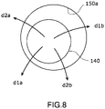
- FIG. 8 is a plan view showing one example of an operation of moving the insert 140 inside the detection hole 150a according to the embodiment.
- the controller 300 causes the rotary joint JB1 to rotate in its both rotational directions d1a and dlb, and when a contact between the insert 140 and the inner wall surface of the detection hole 150a is detected, stops the rotary joint JB1 from rotating.
- the controller 300 may determine the presence or absence of the contact based on deviations of detection values of the rotation sensor E1 of the driver DB1 and deviations of detection values of a current sensor (not shown) of the driver DB1.
- the insert 140 comes into contact with the inner wall surface of the detection hole 150a. Accordingly, when the insert 140 comes into contact with the inner wall surface, and immediately after the insert 140 comes into contact with the inner wall surface, movements of the links 121B and 122B due to rattling (e.g., backlash) at the rotary joints JB1 and JB2 are suppressed.
- rattling e.g., backlash
- step S106 the controller 300 operates the rotary joint JB2, which is a different rotary joint of the arm 120B from the rotary joint JB1, to move the insert 140 inside the detection hole 150a in the horizontal direction, i.e., laterally in relation to the detection hole 150a.
- the controller 300 sets the gain of the servomotor M6 of the driver DB2 to be relatively low.
- the controller 300 sets the gain of the servomotor M5 of the driver DB1 of the rotary joint JB1, which is a different rotary joint from the rotary joint JB2, to be lower than the gain of the servomotor M6. As shown in FIG. 8 , the controller 300 causes the rotary joint JB2 to rotate in its both rotational directions d2a and d2b, and when a contact between the insert 140 and the inner wall surface of the detection hole 150a is detected, stops the rotary joint JB2 from rotating.
- step S105 it is possible that, before the insert 140 comes into contact with the inner wall surface, the rotary joint JB1 continues rotating for a certain period of time, and thereby the torque of the servomotor M5 rises. In this case, it is possible that the insert 140 bounces off the inner wall surface of the detection hole 150a.
- step S106 in a state where the insert 140 has come close to the inner wall surface of the detection hole 150a, the rotary joint JB2 starts rotating. For this reason, the rise of the torque of the servomotor M6 before the insert 140 comes into contact with the inner wall surface is low.
- the direction in which the insert 140 is moved by the rotary joint JB2 is different from, e.g., crosses, the direction in which the insert 140 is moved by the rotary joint JB1. Accordingly, when a contact between the insert 140 and the inner wall surface of the detection hole 150a is detected, the rotation of the rotary joint JB2 can be stopped in a state where the insert 140 is in contact with the inner wall surface. Consequently, the position of the insert 140 in the horizontal direction can be made corresponding to the position of the inner wall surface in the horizontal direction. The order of these steps S105 and S106 may be reversed.
- step S107 the controller 300 detects the position of the insert 140 in relation to the robot 100 when the insert 140 has come into contact with the inner wall surface of the detection hole 150a. That is, the controller 300 detects the position of the insert 140 in relation to the robot 100 when the rotation of the rotary joint JB2 is stopped.
- the position calculation unit 316 detects the position and the posture of the interfacing surface of the end effector 110B from detection values of the rotation sensors E5 to E8 of the arm 120B. The position calculation unit 316 detects, for example, as shown in FIG.
- FIG. 9 is a plan view showing one example of three contact states, in each of which the insert 140 is in contact with the detection hole 150a, according to the embodiment.
- step S108 the controller 300 determines whether or not the number of detected positions of the insert 140 is three. In a case where the number of detected positions of the insert 140 is three (Yes in step S108), the flow proceeds to step S109. In a case where the number of detected positions of the insert 140 is less than three (No in step S108), the controller 300 performs steps S105 to S107 again.
- step S109 the controller 300 detects the position of the detection hole 150a in the horizontal direction in relation to the robot 100 by using the information about the three positions of the insert 140 in relation to the robot 100 and information, stored in the storage unit 317, about the detection hole 150a. Specifically, as shown in FIG. 9 , the position of the center axis 150Ca of the detection hole 150a in the horizontal direction is detected as the position of the center axis of a circular cylinder in the horizontal direction, the circular cylinder passing through the three positions of the center axis 140C of the insert 140.
- step S110 the controller 300 determines whether or not the positions of all the detection holes 150a in the horizontal direction in relation to the robot 100 have been detected. In a case where the positions of all the detection holes 150a in the horizontal direction in relation to the robot 100 have been detected (Yes in step S110), the flow proceeds to step S111. In a case where the positions of all the detection holes 150a in the horizontal direction in relation to the robot 100 have not been detected yet (No in step S110), the flow returns to step S104, and the controller 300 performs the process in step S104 and the following processes again for the detection hole 150a whose position in the horizontal direction in relation to the robot 100 has not been detected. In this example, the same arm 120B and the same insert 140 are used for all the detection holes 150a. This makes it possible to reduce discrepancies in detection results that are caused by, for example, differences in characteristics and performance between the arm 120A and the arm 120B.
- step S111 the controller 300 detects the position and the posture of the robot 100 in the horizontal direction in relation to the two detection holes 150a by using the information about the positions of the two detection holes 150a in the horizontal direction in relation to the robot 100. Based on the detection results, the controller 300 may detect the position and the posture of the robot 100 in the horizontal direction in relation to the belt conveyer 604A and/or the workplace WPA. The controller 300 stores the detection results in the storage unit 317.
- the controller 300 can detect the position and the posture of the robot 100 in the horizontal direction in relation to the workplace WPA and/or a component(s) of the workplace WPA. If two or more jigs 150 are disposed on each of the components of the workplace WPA, the controller 300 can detect the position and the posture of the robot 100 in the horizontal direction in relation to each of these components.
- the processes in steps S101 to S111 may be performed by using the arm 120A. In the processes in steps S101 to S111, processes for one detection hole 150a may be performed by using the arm 120A, whereas processes for another detection hole 150a may be performed by using the arm 120B.
- the position of one detection hole 150a in the horizontal direction may be detected by using the positions of the insert 140 at four or more contact locations where the insert 140 contacts the detection hole 150a.
- the processes in steps S104 to S110 may be performed for three or more detection holes 150a, and the positions of the three or more detection holes 150a in the horizontal direction may be used to detect the position and the posture of the robot 100.
- the controller 300 performs processes in the same manner as in the first detection mode.
- the controller 300 may cause the robot 100 to operate by manipulation control in accordance with manipulation information outputted from the manipulation input device 200 corresponding to manipulation inputs by the user P, and the controller 300 may eliminate the processes in steps S102 and S103.
- a program executed by the controller 300 in the second detection mode need not be a program corresponding to the workplace.
- FIG. 10 is a flowchart showing another example of operations of the robot system 1 according to the embodiment.
- FIG. 10 shows the case of detecting the position of the robot 100 in the vertical direction.
- the user P inputs, into the manipulation input device 200, a command to detect the position of the robot 100 in the vertical direction in the first detection mode and information about the workplace WPA in which the robot 100 is disposed.
- the controller 300 receives the command and the information.
- the processes in steps S202 and S203 are the same as those in steps S102 and S103.
- the number of detection holes 150a used in the detection of the position of the robot 100 in the vertical direction may be at least one. In this example, the number of detection holes 150a used in the detection is one.
- step S204 based on an estimated position of the detection hole 150a, the controller 300 operates the arm 120B of the robot 100 to move the insert 140 to a position above the top surface 150b of the jig 150 around the top-end opening of the detection hole 150a.
- the controller 300 operates the linear-motion joint JB3 to lower the insert 140 from the position above the top surface 150b onto the top surface 150b.
- the controller 300 moves the insert 140 of the arm 120B.
- the controller 300 stops lowering the linear-motion joint JB3.
- the controller 300 sets the gain of the servomotor M7 of the driver DB3 to be relatively low.
- the gain of the servomotor M7 may be about the same as the gain of the servomotor M5 of the rotary joint JB1 in step S105 of FIG. 7 .
- the gain of the servomotor M7 may be such a gain that when the lowered link 123B or end effector 110B comes into contact with another physical object, the servomotor M7 stops rotating.
- step S205 the controller 300 detects the position of the insert 140 in relation to the robot 100 when the insert 140 has come into contact with the top surface 150b of the jig 150.
- the controller 300 detects the position of the insert 140 in relation to the robot 100 when the lowering of the linear-motion joint JB3 is stopped.
- step S206 the controller 300 determines whether or not the number of detected positions of the insert 140 is three. In a case where the number of detected positions of the insert 140 is three (Yes in step S206), the flow proceeds to step S207. In a case where the number of detected positions of the insert 140 is less than three (No in step S206), the controller 300 performs steps S204 and S205 again.
- step S207 based on the three positions of the insert 140 in relation to the robot 100, the controller 300 detects the position of the top surface 150b of the jig 150 in the vertical direction in relation to the robot 100. For example, by averaging the three positions of the insert 140, the controller 300 may detect the position of the top surface 150b in the vertical direction. The position of the top surface 150b in the vertical direction corresponds to the position of the top-end opening of the detection hole 150a in the vertical direction.
- step S208 the controller 300 uses the information about the position of the top-end opening of the detection hole 150a in the vertical direction in relation to the robot 100 and information, stored in the storage unit 317, about the jig 150 and the belt conveyer 604A to detect the position of the robot 100 in the vertical direction in relation to the belt conveyer 604A. Further, the controller 300 may detect the position of the robot 100 in the vertical direction in relation to the workplace WPA. The controller 300 stores the detection results in the storage unit 317.
- the controller 300 can detect the position of the robot 100 in the vertical direction in relation to the workplace WPA and/or a component(s) of the workplace WPA. If the jig 150 is disposed on each of the components of the workplace WPA, the controller 300 can detect the position of the robot 100 in the vertical direction in relation to each of these components.
- the processes in steps S201 to S208 may be performed by using the arm 120A.
- the position of the top-end opening of one detection hole 150a in the vertical direction may be detected by using the position(s) of the insert 140 at one, two, or four or more contact locations where the insert 140 contacts the surrounding of the detection hole 150a.
- the processes in steps S204 to S207 may be performed for two or more detection holes 150a, and the positions of the respective two or more detection holes 150a in the vertical direction may be used to detect the position of the robot 100 in the vertical direction.
- the controller 300 performs processes in the same manner as in the first detection mode.
- the controller 300 may cause the robot 100 to operate by manipulation control in accordance with manipulation information outputted from the manipulation input device 200 corresponding to manipulation inputs by the user P, and the controller 300 may eliminate the processes in steps S202 and S203.
- the controller 300 may cause the robot 100 to perform an operation of indicating a type of control that is currently being performed among multiple types of control corresponding to respective comparison objects whose positions are to be compared with the position of the robot 100, i.e., the controller 300 may cause the robot 100 to perform an operation of indicating a current comparison object.
- the comparison objects include the workplaces WPA and WPB and components disposed in the workplaces WPA and WPB, such as the belt conveyers and the placement tables.
- the controller 300 may indicate types of respective comparison objects by utilizing the order of detection holes 150a, in each of which the insert 140 is to be inserted by the robot 100. Alternatively, at least one additional detection hole 150a that is not to be used for detecting the position of the robot 100 may be included among the detection holes 150a.
- a detection mode program may be set for each comparison objects.
- the comparison object may be associated with the following information: the presence or absence of an operation of the robot 100 inserting the insert 140 into the additional detection hole 150a; the number of additional detection holes 150a of the comparison object, in each of which the insert 140 is to be inserted; and the order of the insertion of the insert 140 into each additional detection hole 150a among the order of insertions of the insert 140 into all the detection holes 150a, and the like.
- This allows the user P to recognize a currently executed program and/or a comparison object corresponding to the currently executed program by looking at the operation of the robot 100, and thereby to determine whether a proper program is being executed. This makes it possible to suppress erroneous detection of the position of the robot 100.
- the robot system 1 is used for detecting the position of the robot 100 when the robot 100 is moved.
- the robot system 1 may be used in any case in which the robot 100 is disposed at a predetermined position.
- the robot system 1 may be used in any case in which the positions of a target object and the robot 100 relative to each other need to be detected.
- the inserts 140 which are downward projections from the respective end effectors 110A and 110B, are described as one example of the contacting structures of the respective arms 120Aand 120B.
- the detection holes 150a which are recesses in the respective jigs 150 disposed in a workplace, are described as one example of the detection subjects.
- the contacting structures need not be separated from, but may be integrated with, the end effectors 110A and 110B or the links 124A and 124B of the arms 120A and 120B.
- the detection subjects need not be separated from, but may be integrated with, a component of the workplace, such as a belt conveyer.
- each contacting structure may be a recess
- each detection subject may be a projection
- the arm 120A and/or the arm 120B may include a member including a recess such as a hole, and a member such as the jig 150 that includes a projection such as a shaft may be disposed in the workplace.
- the controller 300 may cause the arm 120A or 120B to insert the projection, which projects upward, into the recess, which faces downward, and to move the recess laterally to bring at least three locations on the inner wall surface of the recess into contact with the projection.
- the controller 300 may cause the arm 120A or 120B to move the recess downward to bring at least one location on a surface around the recess into contact with the projection.
- each contacting structure may be a projection
- each detection subject may also be a projection
- the arm 120A and/or the arm 120B may include a member including a projection such as the insert 140, and a member such as the jig 150 that includes a projection such as a shaft may be disposed in the workplace. In the case of detecting the position of the robot 100 in the horizontal direction, for example, as shown in FIG.
- the controller 300 may cause the arm 120A or 120B to move a contacting structure 140A laterally, the contacting structure 140A having a columnar shape and projecting downward, such that the contacting structure 140A comes into contact with at least three locations on an outer peripheral surface of a detection subject 150Aa of a jig 150A, the detection subject 150Aa having a columnar shape and projecting upward.
- the controller 300 may cause the arm 120A or 120B to move the contacting structure 140A downward, such that the contacting structure 140A comes into contact with at least one location on a top surface 150Ab of the jig 150A around the detection subject 150Aa.
- FIG. 11 is a plan view showing one example of contact states, in each of which the contacting structure 140A is in contact with the detection subject 150Aa according to one variation of the embodiment.
- the industrial robot 100 is described as one example of a mechanical apparatus to which the technique of the present disclosure is applicable.
- the technique of the present disclosure may be applied to a mechanical apparatus different from an industrial robot.
- the mechanical apparatus to which the technique of the present disclosure is applied may be a service robot, humanoid, or the like.
- the service robot is a robot for use in various services, such as nursing care, medical care, cleaning, security guarding, guiding, rescuing, cooking, product offering, etc.
- a position detection method is a position detection method of detecting a position of a robot in relation to a target object, the robot including an arm.
- the method includes: (a) causing the arm, on which a contacting structure is disposed, to position the contacting structure laterally in a horizontal direction in relation to a first detection subject that is one of at least two detection subjects disposed on the target object; (b) causing the arm to move the contacting structure laterally to bring the contacting structure into contact with at least three locations on a surface of the first detection subject; (c) detecting positions of the contacting structure in relation to the robot when the contacting structure comes into contact with the at least three locations, respectively; (d) detecting a position of the first detection subject in relation to the robot by using the detected at least three positions of the contacting structure; (e) performing same steps as the steps (a) to (d) for another detection subject, different from the first detection subject, of the at least
- the technique of the present disclosure may be a program to be executed for performing the above position detection method, or may be a non-transitory computer-readable storage medium storing the program therein. It is needless to say that the program can be distributed via a transmission medium such as the Internet.
Landscapes
- Engineering & Computer Science (AREA)
- Robotics (AREA)
- Mechanical Engineering (AREA)
- Manipulator (AREA)
Abstract
Description
- This application claims priority to and the benefit of
Japanese Patent Application No. 2019-225623, filed on December 13, 2019 - The present disclosure relates to a position detection method, a controller, and a robot system.
- Conventionally, it has been done to teach a robot a positional relationship between the robot and a work object. For example,
Patent Literature 1 discloses a method of teaching a robot a position within a work environment by using a tactile sensor. The robot includes an arm with an end effector. The end effector includes a tactile sensor device including a touch sensitive surface. The robot brings the touch sensitive surface into contact with a work object, and the tactile sensor device generates a signal indicating the position of the contact with respect to the touch sensitive surface. Further, by using information including the generated signal, the position of the contact in the work environment is taught to the robot. - PTL 1:
Japanese National Phase PCT Laid-Open Application Publication No. 2006-503721 - In
Patent Literature 1, the tactile sensor device including the touch sensitive surface is used to detect a positional relationship between the robot and the work object. In a case where high positional precision is required, a high-precision tactile sensor device is necessary, which causes increase in cost and increase in complexity of equipment. Moreover, when the robot with the tactile sensor device mounted thereto performs work, it may cause deterioration in the precision of the tactile sensor device, and consequently, calibration may become necessary, which complicates the work for the detection. - An objective of the present disclosure is to provide a position detection method, a controller, and a robot system that simplify the detection of a positional relationship between a robot and a target object.
- In order to achieve the above objective, a position detection method according to one aspect of the present disclosure is a position detection method of detecting a position of a robot in relation to a target object, the robot including an arm. The method includes: (a) causing the arm, on which a contacting structure is disposed, to position the contacting structure laterally in a horizontal direction in relation to a first detection subject that is one of at least two detection subjects disposed on the target object; (b) causing the arm to move the contacting structure laterally to bring the contacting structure into contact with at least three locations on a surface of the first detection subject; (c) detecting positions of the contacting structure in relation to the robot when the contacting structure comes into contact with the at least three locations, respectively; (d) detecting a position of the first detection subject in relation to the robot by using the detected at least three positions of the contacting structure; (e) performing same steps as the steps (a) to (d) for another detection subject, different from the first detection subject, of the at least two detection subjects; and (f) detecting the position of the robot in relation to the target object by using the positions of the at least two detection subjects in relation to the robot and using positions of the at least two detection subjects in relation to the target object.
- The technique of the present disclosure makes it possible to simplify the detection of a positional relationship between the robot and the target object.
-
-
FIG. 1 shows one example of the configuration of a robot system according to an embodiment. -
FIG. 2 is a side view showing one example of the configuration of a robot according to the embodiment. -
FIG. 3 is a side view showing one example of the configuration of an end effector according to the embodiment. -
FIG. 4 is a plan view showing one example of members each including a detection hole. -
FIG. 5 is a block diagram showing one example of the configuration of a controller and its peripheral components according to the embodiment. -
FIG. 6 is a block diagram showing one example of a functional configuration of the controller according to the embodiment. -
FIG. 7 is a flowchart showing one example of operations of the robot system according to the embodiment. -
FIG. 8 is a plan view showing one example of an operation of moving an insert inside the detection hole according to the embodiment. -
FIG. 9 is a plan view showing one example of three contact states, in each of which the insert is in contact with the detection hole, according to the embodiment. -
FIG. 10 is a flowchart showing another example of operations of the robot system according to the embodiment. -
FIG. 11 is a plan view showing one example of contact states, in each of which a contacting structure is in contact with a detection subject according to one variation of the embodiment. - First, each exemplary aspect of the present disclosure is described. A position detection method according to one aspect of the present disclosure is a position detection method of detecting a position of a robot in relation to a target object, the robot including an arm. The method includes: (a) causing the arm, on which a contacting structure is disposed, to position the contacting structure laterally in a horizontal direction in relation to a first detection subject that is one of at least two detection subjects disposed on the target object; (b) causing the arm to move the contacting structure laterally to bring the contacting structure into contact with at least three locations on a surface of the first detection subject; (c) detecting positions of the contacting structure in relation to the robot when the contacting structure comes into contact with the at least three locations, respectively; (d) detecting a position of the first detection subject in relation to the robot by using the detected at least three positions of the contacting structure; (e) performing same steps as the steps (a) to (d) for another detection subject, different from the first detection subject, of the at least two detection subjects; and (f) detecting the position of the robot in relation to the target object by using the positions of the at least two detection subjects in relation to the robot and using positions of the at least two detection subjects in relation to the target object.
- According to the above aspect, for each detection subject, the positions of the contacting structure in relation to the robot when the contacting structure comes into contact with the at least three locations on the detection subject, respectively, are detected, and thereby the position of each detection subject in relation to the robot is detected. Further, the position of the robot in relation to the target object is detected by using the position of each detection subject in relation to the robot. The position detection as above can be realized by disposing the contacting structure on the arm of the robot and through the above-described operations by the robot. Therefore, the detection of the positional relationship between the robot and the target object is simplified.
- In the position detection method according to the aspect of the present disclosure, each of the at least two detection subjects may be one of a recess or a projection, the projection being insertable in the recess. The contacting structure may be the other of the recess or the projection. The method may include, in the step (a), positioning the contacting structure laterally in relation to the first detection subject by moving the contacting structure such that the projection is inserted in the recess. According to this aspect, in the step (b), the contacting structure is moved laterally in a state where the projection is inserted in the recess. The range of movement of the contacting structure is restricted by the recess. Consequently, an arm operation for bringing the contacting structure and the detection subject into contact with each other is made simple and fast.
- In the position detection method according to the aspect of the present disclosure, the method may include, in the step (f), detecting the position and an orientation of the robot in relation to the target object. According to this aspect, the detection of a precise positional relationship between the robot and the target object is simplified.
- In the position detection method according to the aspect of the present disclosure, the arm may include at least two joints. The method may include, in the step (b), at each of the at least three locations, performing a first operation of operating a first joint, which is one of the at least two joints, to bring the contacting structure into contact with the surface of the first detection subject, and then performing a second operation of operating a second joint, which is another one of the at least two joints, to bring the contacting structure into contact with the surface of the first detection subject. According to this aspect, in the first operation, it is possible that due to a large moving amount of the contacting structure, the contacting structure collides against and bounces off the surface of the detection subject. In the second operation, the moving amount of the contacting structure can be made small, and therefore, the contacting structure can be kept in contact with the surface of the detection subject. In each of the first operation and the second operation, the contacting structure is brought into contact with the detection subject while the first joint or the second joint is operating, and thereby influence on the operations, the influence being caused by mechanical rattling (e.g., backlash) at the first joint and the second joint, is reduced. This makes it possible to detect a precise position of each part of the arm at the time of making a contact. Since the first joint and the second joint operate independently of each other, a moving amount of each joint until the contacting structure and the detection subject come into contact with each other can be readily detected.
- In the position detection method according to the aspect of the present disclosure, the first joint and the second joint may enable the arm to operate in a manner to move the contacting structure laterally. According to this aspect, influence on the operation of the first joint, the influence being caused by mechanical rattling (e.g., backlash) at the second joint, is reduced, and also, influence on the operation of the second joint, the influence being caused by mechanical rattling (e.g., backlash) at the first joint, is reduced.
- In the position detection method according to the aspect of the present disclosure, the method may include: in the first operation, lowering a gain of a second servomotor that drives the second joint than a gain of a first servomotor that drives the first j oint; and in the second operation, lowering the gain of the first servomotor than the gain of the second servomotor. According to this aspect, in the first operation, influence on the operation of the first joint driven by the first servomotor, the influence being caused by the driving force of the second servomotor for maintaining the state of the second joint, is reduced, whereas in the second operation, influence on the operation of the second joint driven by the second servomotor, the influence being caused by the driving force of the first servomotor for maintaining the state of the first joint, is reduced.
- The position detection method according to the aspect of the present disclosure may further include: (g) causing the arm to perform an operation of indicating a type of control that is currently being performed among multiple types of control corresponding to respective target objects. According to this aspect, a user of the robot can visually recognize a process that is currently being performed by the robot.
- The position detection method according to the aspect of the present disclosure may further include: (a1) causing the arm to position the contacting structure to a position above a peripheral surface around the first detection subject; (b1) causing the arm to lower the contacting structure to bring the contacting structure into contact with at least one location on the peripheral surface; (c1) detecting a height position of the contacting structure when the contacting structure comes into contact with each of the at least one location, the height position being a position of the contacting structure in a height direction in relation to the robot; (d1) detecting a height position of the first detection subject in relation to the robot by using the detected at least one height position of the contacting structure; and (e1) detecting a height position of the robot in relation to the target object by using the height position of the first detection subject in relation to the robot. According to this aspect, the detection of the height position of the robot in relation to the target object can be realized by disposing the contacting structure on the arm of the robot and through the above-described operations by the robot.
- A controller according to one aspect of the present disclosure is a controller for performing the position detection method according to the aspect of the present disclosure. The controller: performs the step (a) in accordance with manipulation information outputted from a manipulation input device with which to manipulate the robot, the manipulation input device receiving an input of a manipulation of the robot; and performs the steps (b) to (f) autonomously in accordance with a program. According to this aspect, the controller can perform the steps (a) to (f) even if an approximate position of each detection subject in relation to the robot is unknown.
- A controller according to one aspect of the present disclosure is a controller for performing the position detection method according to the aspect of the present disclosure. The controller may perform the steps (a) to (f) autonomously in accordance with a program. According to this aspect, the controller can perform the steps (a) to (f) autonomously.
- A robot system according to one aspect of the present disclosure includes: a controller that performs the position detection method according to the aspect of the present disclosure and controls an operation of the robot; and the robot. According to this aspect, the same advantageous effects as those of the controller according to the aspect of the present disclosure are obtained.
- In the robot system according to the aspect of the present disclosure, the controller may: perform the step (a) in accordance with manipulation information outputted from a manipulation input device with which to manipulate the robot, the manipulation input device receiving an input of a manipulation of the robot; and perform the steps (b) to (f) autonomously in accordance with a program. According to this aspect, the same advantageous effects as those of the controller according to the aspect of the present disclosure are obtained.
- In the robot system according to the aspect of the present disclosure, the controller may perform the steps (a) to (f) autonomously in accordance with a program. According to this aspect, the same advantageous effects as those of the controller according to the aspect of the present disclosure are obtained.
- Hereinafter, embodiments of the present disclosure are described with reference to the drawings. The embodiments below each describe comprehensive or specific examples. Among components described in the embodiments below, components that are not recited in an independent claim defining the most generic concept of the present disclosure are described as optional components. Each of the accompanying drawings is a schematic drawing, and is not necessarily an exactly illustrated drawing. In each drawing, substantially the same components are denoted by the same reference signs, and in some cases, redundant descriptions are omitted or simplified. In the present specification and the claims, "an apparatus" or "a device" can mean not only a single apparatus or a single device, but also a system including multiple apparatuses or multiple devices.
- Hereinafter, the configuration of a
robot system 1 according to an embodiment is described.FIG. 1 shows one example of the configuration of therobot system 1 according to the embodiment. As shown inFIG. 1 , therobot system 1 includes arobot 100, amanipulation input device 200, acontroller 300,imaging devices 400, and apresentation device 500. As a non-limiting example, in the present embodiment, therobot system 1 causes therobot 100 to autonomously perform two different types of work at different positions, respectively. - For example, in a workplace WPA, the
robot 100 packs articles WA conveyed by abelt conveyer 601A into acontainer box 603A on a placement table 602A, and places thecontainer box 603A in which the articles WA have been packed onto anotherbelt conveyer 604A, which conveys thecontainer box 603A to another workplace. Also, in a workplace WPB, therobot 100 packs articles WB conveyed by abelt conveyer 601B into acontainer box 603B on a placement table 602B, and places thecontainer box 603B in which the articles WB have been packed onto anotherbelt conveyer 604B, which conveys thecontainer box 603B to another workplace. It is necessary to move therobot 100 between the workplace WPA and the workplace WPB. Each time therobot 100 is moved, it is necessary to teach a position to therobot 100. Specifically, in the workplace WPA, it is necessary to store, in thecontroller 300, the positions of, for example, therobot 100 and thebelt conveyer 601A relative to each other. In the workplace WPB, it is necessary to store, in thecontroller 300, the positions of, for example, therobot 100 and thebelt conveyer 601B relative to each other. - In the present embodiment, in each of the workplace WPA and the workplace WPB, based on the above relative positions, the
controller 300 causes therobot 100 to autonomously perform predetermined work, such as packing work, in accordance with a program. The work performed by therobot 100 is not limited to the work illustratively described in the present embodiment, but may be any work. Thecontroller 300 controls the operations of therobot 100 by autonomous control and manipulation control. The autonomous control causes therobot 100 to operate autonomously in accordance with a program. The manipulation control causes therobot 100 to operate in accordance with manipulation information corresponding to a manipulation that is inputted via themanipulation input device 200. -
FIG. 2 is a side view showing one example of the configuration of therobot 100 according to the embodiment. As shown inFIG. 1 andFIG. 2 , in the present embodiment, therobot 100 is an industrial robot as a non-limiting example. Therobot 100 includesend effectors arms 120Aand 120B, abase 130, and inserts 140. Theend effectors arms respective end effectors arms arms base 130. Thebase 130 is placed on a movable apparatus such as a transporter, and is thus movable. Examples of the transporter include wheels and an AGV (Automated Guided Vehicle). Theinserts 140 are disposed on therespective end effectors inserts 140 are disposed on the distal ends of therespective arms robot 100. - The
arms arms respective end effectors arms arms arms arm 120A is disposed to be shifted downward in the direction of the first axis S1 in relation to thearm 120B. Therobot 100 is a coaxial dual-arm robot. - The
arm 120A includeslinks 121A to 124A, joints JA1 to JA4, and drivers DA1 to DA4. Thearm 120B includeslinks 121B to 124B, joints JB1 to JB4, and drivers DB1 to DB4. The drivers DA1 to DA4 and DB1 to DB4 include, for example, electric motors using electricity as the source of power. In the present embodiment, the drivers DA1 to DA4 and DB1 to DB4 include servomotors. The drivers DA1 to DA4 and DB1 to DB4 are controlled by thecontroller 300 to drive the joints JA1 to JA4 and JB1 to JB4, respectively. Accordingly, thearms arms - The
links base 130 via the rotary joints JA1 and JB1, respectively, such that thelinks links links links links links links 123Aand 123B can be lifted and lowered along respective vertical third axes S3a and S3b. Thelinks links links links links end effectors - The term "horizontal direction" herein means, in a case where the
robot 100 is disposed on a horizontal surface such as a horizontal floor surface, a horizontal direction parallel to the surface. The term "vertical direction" herein means, in the same case, a vertical direction perpendicular to the aforementioned surface. The term "upward" herein means, in the same case, a direction from the lower side toward the upper side. The term "downward" herein means, in the same case, a direction from the upper side toward the lower side. The term "lateral" or "laterally" herein means, in the same case, a direction extending along the aforementioned surface. -
FIG. 3 is a side view showing one example of the configuration of theend effector 110A according to the embodiment. As shown inFIG. 2 andFIG. 3 , theend effectors end effector 110A is described, and the description of the configuration of theend effector 110B is omitted. Theend effector 110A includes aconnector 111, asupport 112, adriver 113, and agripper 114. - The
support 112 extends in a direction perpendicular the fourth axis S4a. Theconnector 111 is disposed on one end of thesupport 112 in its extending direction. Thedriver 113 is disposed on the other end of thesupport 112 in its extending direction. Theconnector 111 is connected to the mechanical interface of thelink 124A via theinsert 140. Thedriver 113 is mechanically connected to twogripping claws 114a of thegripper 114, and is capable of causing the grippingclaws 114a to move toward each other and away from each other. Eachgripping claw 114a extends in a direction crossing the fourth axis S4a. In the present embodiment, eachgripping claw 114a extends in a direction perpendicular to the fourth axis S4a. The grippingclaws 114a grip a workpiece such as an article WA or WB by moving toward each other, and stop gripping the workpiece by moving away from each other. Thedriver 113 includes, for example, an electric motor that uses electricity as the source of power. In the present embodiment, thedriver 113 includes a servomotor. Thedriver 113 is controlled by thecontroller 300 to drive the grippingclaws 114a. - The
insert 140 includes ashaft 141 and aconnector 142. In the present embodiment, a single member serves as both theshaft 141 and theconnector 142. Alternatively, theshaft 141 and theconnector 142 may be dividable from each other. Theconnector 142 is connected to the mechanical interface of thelink 124A. Theconnector 142 is disc-shaped and includes a circular surface similar to the surface of the mechanical interface. Theconnector 142 includes aprotrusion 142a on the aforementioned circular surface. Theprotrusion 142a may be integrated with theconnector 142, or may be attachable to and detachable from theconnector 142. Theprotrusion 142a is an annular protrusion that has a planar shape similar to a planar shape of an annular groove 124Aa formed in the surface of the mechanical interface, and is fittable into the groove 124Aa. Theconnector 142 is positioned at a fixed position in relation to the surface of the mechanical interface as a result of theprotrusion 142a being fitted into the groove 124Aa. The shape of each of theprotrusion 142a and the groove 124Aa is not limited to an annular shape, so long as the positioning of theconnector 142 can be performed by fitting theprotrusion 142a to the groove 124Aa. Alternatively, the above-described protrusion and groove may be disposed on thelink 124A and in theconnector 142, respectively. - The
shaft 141 extends in a direction perpendicular to the circular surface of theconnector 142 and extends downward opposite theprotrusion 142a in a manner to penetrate theconnector 111 and thesupport 112 of theend effector 110A. Theshaft 141 projects downward from thesupport 112. As a non-limiting example, in the present embodiment, theshaft 141 projects downward but not beyond thedriver 113 and/or thegripper 114 of theend effector 110A. When the positioning of theconnector 142 is performed by fitting theprotrusion 142a to the groove 124Aa, theshaft 141 extends coaxially with the fourth axis S4a. That is, the center axis of theshaft 141 coincides with the fourth axis S4a. - The
connector 142 includes anannular groove 142b in its circular surface opposite theprotrusion 142a. Theconnector 111 of theend effector 110A includes aprotrusion 111a on its surface opposite thesupport 112. Theprotrusion 111a may be integrated with theconnector 111, or may be attachable to and detachable from theconnector 111. Theprotrusion 111a is an annular protrusion that has a planar shape similar to a planar shape of thegroove 142b, and is fittable into thegroove 142b. Theconnector 111 of theend effector 110A is positioned at a fixed position in relation to theinsert 140 and thelink 124A as a result of theprotrusion 111a being fitted into thegroove 142b. The shape of each of theprotrusion 111a and thegroove 142b is not limited to an annular shape, so long as the positioning of theconnector 111 can be performed by fitting theprotrusion 111a to thegroove 142b. Alternatively, the above-described protrusion and groove may be disposed on theconnector 142 and in theconnector 111, respectively. - The
insert 140 as above is directly fixed to the link 124Ain a state where theconnector 142 is sandwiched between thelink 124A and theend effector 110A. Therobot 100 can perform work in a state where theinsert 140 is attached to thelink 124A. Alternatively, theinsert 140 may be directly fixed to theend effector 110A and indirectly fixed to thelink 124A via theend effector 110A. Theinsert 140 is one example of a contacting structure, and is one example of a projection. - The
robot system 1 includes, in each of the workplace WPA and the workplace WPB,detection holes 150a (seeFIG. 4 ), into each of which theshaft 141 of theinsert 140 is inserted for detecting the position of therobot 100. Thedetection holes 150a extend in the vertical direction. For example, members in which therespective detection holes 150a are formed are disposed at predetermined positions, respectively, in each of the workplace WPA and the workplace WPB. Each predetermined position may be a precisely known position or a precisely detectable position. -
FIG. 4 is a plan view showing one example of the members including the respective detection holes. As shown inFIG. 4 , for example, in the workplace WPA, jigs 150 with therespective detection holes 150a formed therein may be disposed on thebelt conveyer 604A. InFIG. 4 , as a non-limiting example, eachdetection hole 150a has a cylindrical shape with a circular cross section. For example, thedetection hole 150a may have any shape, so long as at least three arbitrary locations on the inner wall surface of thedetection hole 150a are detectable and by using the detected three locations, for example, a reference position such as the center or the center axis of thedetection hole 150a, or the sectional shape of thedetection hole 150a, is detectable. For instance, thedetection hole 150a may have a pillar-like shape with, for example, an ellipsoidal cross section, an oval cross section, or a polygonal cross section. - The
jigs 150 may be disposed, in the workplace WPA, on each of components whose respective positions relative to therobot 100 need to be obtained, such as thebelt conveyer 601A and the placement table 602A. In a case where the positions of the respective components relative to each other are known or detectable, thejigs 150 may be disposed on at least one of these components. At least twojigs 150, i.e., at least twodetection holes 150a, are disposed in each of the workplace WPA and the workplace WPB. Eachdetection hole 150a is one example of a detection subject, and is one example of a recess. - As shown in
FIG. 1 , theimaging device 400 is disposed in each of the workplace WPA and the workplace WPB. In each of the workplace WPA and the workplace WPB, theimaging device 400 captures an image of at least part of the following components: the placement table 602A or 602B; and thebelt conveyers belt conveyers imaging device 400 may be disposed on any of the components in the workplace. Theimaging device 400 may be disposed on therobot 100. In the present embodiment, as a non-limiting example, theimaging device 400 includes a visible camera capable of capturing a digital moving image that is a visible image. For example, theimaging device 400 performs image capturing in accordance with a command from thecontroller 300, and transmits, for example, signals of a captured image to thecontroller 300. - The
presentation device 500 presents, to a user P of therobot system 1, an image, voice, sound, etc., that are received from thecontroller 300 and that are intended for operating therobot system 1. Non-limiting examples of thepresentation device 500 include a liquid crystal display and an organic or inorganic electro-luminescence display. Thepresentation device 500 may include a speaker that outputs voice and sound. For example, thepresentation device 500 presents an image captured by theimaging device 400 to the user P operating themanipulation input device 200. - The
manipulation input device 200 receives inputs of, for example, various information, data, and commands, and outputs the received information and so forth to thecontroller 300. For example, themanipulation input device 200 may include a known input means, such as a lever, a button, a touch panel, a joystick, or a motion capturer. For example, themanipulation input device 200 receives an input of manipulation performed on therobot 100 by the user P, and outputs manipulation information corresponding to the received manipulation to thecontroller 300. Themanipulation input device 200 may receive the manipulation via the aforementioned input means, or may include an input means dedicated for receiving the manipulation. -
FIG. 5 is a block diagram showing one example of the configuration of thecontroller 300 and its peripheral components according to the embodiment. As shown inFIG. 5 , thecontroller 300 is communicably connected to therobot 100, themanipulation input device 200, theimaging device 400, and thepresentation device 500. The mode of communications adopted herein may be any communication mode among wired communications and wireless communications. Thecontroller 300 operates therobot 100 in response to a command received by themanipulation input device 200. Thecontroller 300 outputs, for example, an image captured by theimaging device 400 to thepresentation device 500. - The
controller 300 is electrically connected to servomotors M1 to M8 (referred to as "SM" inFIG. 5 ) of the drivers DA1 to DA4 and DB1 to DB4 of thearms robot 100 via drive circuits C1 to C8 (referred to as "SC" inFIG. 5 ), respectively. The drive circuits C1 to C8 adjust current values of electric currents fed to the servomotors M1 to M8, respectively, in accordance with commands from thecontroller 300. Thecontroller 300 is electrically connected to rotation sensors E1 to E8 (referred to as "EN" inFIG. 5 ), such as encoders, of the drivers DA1 to DA4 and DB1 to DB4. Thecontroller 300 is electrically connected to servomotors M9 and M10 of thedrivers 113 of theend effectors controller 300. Thecontroller 300 is electrically connected to rotation sensors E9 and E10 of thedrivers 113 of theend effectors controller 300. - The
controller 300 includes an arithmetic unit including a processor, memories, and so forth. The arithmetic unit transmits and receives information, data, commands, etc., to and from other devices such as themanipulation input device 200. The arithmetic unit receives detection signals inputted from various sensors, and outputs control signals to controlled objects. The memories include storage devices, and examples of the storage devices include semiconductor memories such as volatile and nonvolatile memories, a hard disk, and an SSD (Solid State Drive). For example, the memories store therein, for example, programs executed by the arithmetic unit and various fixed data. - Functions of the arithmetic unit may be realized by a computer system (not shown) that includes, for example, a processor such as a CPU (Central Processing Unit), a volatile memory such as a RAM (Random Access Memory), and a nonvolatile memory such as a ROM (Read-Only Memory). The functions of the arithmetic unit may be partly or entirely realized as a result of the CPU executing a program stored in the ROM by using the RAM as a work area. The functions of the arithmetic unit may be partly or entirely realized by the aforementioned computer system, or may be partly or entirely realized by a dedicated hardware circuit such as an electronic circuit or an integrated circuit, or may be partly or entirely realized by a combination of the aforementioned computer system and hardware circuit.
- The
controller 300 may include, for example, a microcontroller, an MPU (Micro Processing Unit), an LSI (Large Scale Integration), a system LSI, a PLC (Programmable Logic Controller), or a logic circuit. Multiple functions of thecontroller 300 may be realized as multiple individual chips, respectively, or may be partly or entirely realized as a single chip. The aforementioned circuits may each be a general-purpose circuit or a dedicated circuit. As an LSI, for example, an FPGA (Field Programmable Gate Array), which can be programmed after LSI production, or a reconfigurable processor, which enables connections and/or settings of circuit cells in an LSI to be reconfigured, or an ASIC (Application Specific Integrated Circuit), in which multiple functionality circuits customized for a particular use are integrated as a single chip, may be used. - The
controller 300 may be a single device that performs processes by centralized control, or may be multiple devices that perform distributed control in cooperation with each other, thereby performing the processes. -
FIG. 6 is a block diagram showing one example of the functional configuration of thecontroller 300 according to the embodiment. As shown inFIG. 6 , thecontroller 300 includes the following functional components: an image capturingcontrol unit 311; aninformation processing unit 312;operation command units operation control unit 315; aposition calculation unit 316; and astorage unit 317. Functions of these functional components, except thestorage unit 317, are realized by a computer system and/or a hardware circuit. Thestorage unit 317 is realized by memories. Not all of the above functional components are essential. - The
information processing unit 312 receives various information, data, commands, etc., from themanipulation input device 200, and processes and outputs them to corresponding functional components. For example, theinformation processing unit 312 receives, from themanipulation input device 200, a command to cause theimaging device 400 to capture an image of the workplace WPA or WPB, and outputs the command to the image capturingcontrol unit 311. Theinformation processing unit 312 receives, from themanipulation input device 200, a command that specifies an operation mode of therobot 100, and outputs the received command to, for example, theoperation command units - For instance, examples of the operation mode include: an autonomous operation mode of causing the
robot 100 to perform work by autonomous control; a manipulation-controlled operation mode of causing therobot 100 to perform work by manipulation control; and a detection mode of detecting the position of therobot 100. During the autonomous operation mode, part of the work performed by therobot 100 may be caused by manipulation control. The detection mode may include: a first detection mode in which all the operations performed by therobot 100 in this mode are caused by autonomous control; and a second detection mode in which the operations performed by therobot 100 in this mode are at least partly caused by manipulation control, and the remaining operations performed by therobot 100 in this mode are caused by autonomous control. For example, the work performed herein may be made up of multiple operations by therobot 100 for performing intended processes on a target obj ect. - The image capturing
control unit 311 receives a command from theinformation processing unit 312, and in accordance with the received command, causes the correspondingimaging device 400 to perform an image-capturing operation. The image capturingcontrol unit 311 receives signals of a captured image from theimaging device 400, generates screen-displayable image data from the received signals, outputs the generated image data to thepresentation device 500, and causes thepresentation device 500 to display the image data. - The first
operation command unit 313 functions in the manipulation-controlled operation mode and the second detection mode. The firstoperation command unit 313 generates, in accordance with manipulation information received from themanipulation input device 200, a manipulation-controlled operation command that is a command to operate therobot 100, and outputs the manipulation-controlled operation command to theoperation control unit 315. Specifically, the manipulation-controlled operation command may include, for example, the following commands: commands to cause thearms end effectors drivers 113 of theend effectors end effectors manipulation input device 200 by the user P. - An operation command herein includes at least either one of a position command or a force command, and in the present embodiment, includes a position command. The position command includes, among target values of, for example, a position, a posture, a positional velocity, and a posture velocity of a controlled object such as the
end effector - The second
operation command unit 314 functions in the autonomous operation mode and the first detection mode. The secondoperation command unit 314 generates, in accordance with autonomous operation information stored in thestorage unit 317, an autonomous operation command that is a command to operate therobot 100, and outputs the autonomous operation command to theoperation control unit 315. The autonomous operation command is a command for causing theend effectors operation command unit 314 uses information, stored in thestorage unit 317, about the position and the posture of therobot 100 in relation to a workplace and/or information, stored in thestorage unit 317, about the position and the posture of therobot 100 in relation to components of the workplace. The posture may be the orientation of therobot 100 in the horizontal direction, i.e., the azimuth of therobot 100. - For example, the autonomous operation information may include information about operation details and the order of operations by the
end effectors end effectors arms drivers 113 of theend effectors end effectors end effectors end effectors driver 113 of each of theend effectors end effectors end effectors driver 113 of each of theend effectors - For example, the autonomous operation information corresponding to the autonomous operation mode may be teaching data. The autonomous operation information corresponding to the first detection mode may be data similar to teaching data, and may be data preset by programming.
- The
operation control unit 315 determines, in accordance with the manipulation-controlled operation command or the autonomous operation command received from theoperation command unit robot 100 to drive the servomotors M1 to M10, thereby controlling the feeding of the electric currents. In this control, theoperation control unit 315 may use detection values of, for example, the rotation sensors E1 to E10 and current sensors (not shown) of the servomotors M1 to M10 as feedback information. Alternatively, theoperation control unit 315 may use, as feedback information, command values of the electric currents that are fed to the servomotors M1 to M10 by the drive circuits C1 to C10. Theoperation control unit 315 thus configured performs servo control. Consequently, thearms end effectors controller 300. - The
position calculation unit 316 functions in the first and second detection modes. In each detection mode, theposition calculation unit 316 detects at least either one of the position of therobot 100 in the horizontal direction or the position of therobot 100 in the vertical direction. For example, in the case of detecting the position of therobot 100 in the horizontal direction, therobot 100 inserts, from above, theinsert 140 of theend effector detection holes 150a of the twojigs 150, and moves theinsert 140 in the horizontal direction to bring theinsert 140 into contact with at least three locations on the inner wall surface of eachdetection hole 150a. Theposition calculation unit 316 detects the position of theinsert 140 in relation to therobot 100 when theinsert 140 comes into contact with the inner wall surface. Specifically, theposition calculation unit 316 detects the position of theinsert 140 in relation to therobot 100 based on driving amounts of the joints JA1 to JA4 of thearm 120A, or driving amounts of the joints JB1 to JB4 of thearm 120B, which inserts theinsert 140 in eachdetection hole 150a, i.e., based on detection values of the rotation sensors E1 to E4 or detection values of the rotation sensors E5 to E8. The position in relation to therobot 100 may be a position in relation to a fixed reference position on therobot 100, such as a point of intersection between the first axis S1 and the top surface of thebase 130. - For each
detection hole 150a, theposition calculation unit 316 detects the position of thedetection hole 150a in the horizontal direction in relation to therobot 100 by using the positions of theinsert 140 therein at the three respective contact locations. At the time, theposition calculation unit 316 uses information about thedetection hole 150a, the information being stored in thestorage unit 317. The information about thedetection hole 150a includes the sectional shape and dimensions of thedetection hole 150a. Further, theposition calculation unit 316 uses information about the position of theinsert 140 in relation to therobot 100 and at least the sectional shape information from the information about thedetection hole 150a to detect the center axis of a circular cylinder, the circular cylinder passing through the center axis of theinsert 140 at each of the three contact locations and having a horizontal cross section with the aforementioned sectional shape. Then, theposition calculation unit 316 determines the position of the detected center axis of the circular cylinder in the horizontal direction as the position of thedetection hole 150a in the horizontal direction. - Further, the
position calculation unit 316 uses the information about the position of each of the twodetection holes 150a in the horizontal direction in relation to therobot 100 and information, stored in thestorage unit 317, about the position of eachdetection hole 150a in relation to a component of the workplace in which thejigs 150 are disposed to detect the position and the posture of therobot 100 in the horizontal direction in relation to the component. The posture of therobot 100 in the horizontal direction may be the orientation of therobot 100 in the horizontal direction (i.e., azimuth). Theposition calculation unit 316 may detect the position and the posture of therobot 100 in the horizontal direction in relation to at least one of the components of the workplace, or may detect the positions and the postures of therobot 100 in the horizontal direction in relation to all the components of the workplace. For example, in a case where at least twojigs 150 are disposed on each of all the components, theposition calculation unit 316 may detect the position and the posture of therobot 100 in the horizontal direction in relation to each component. In a case where the positional relationship among the components is known, theposition calculation unit 316 may detect the position and the posture of therobot 100 in the horizontal direction in relation to one of the components. Further, theposition calculation unit 316 may detect the position and the posture of therobot 100 in the horizontal direction in relation to the workplace by using information, stored in thestorage unit 317, about the position of each of the components in the workplace. Theposition calculation unit 316 stores the detected position(s) and posture(s) of therobot 100 in the horizontal direction in thestorage unit 317. - In the workplace, the
jigs 150 each including thedetection hole 150a and therobot 100 are disposed. The aforementioned component of the workplace is a component on which thejigs 150 are disposed, for example, a belt conveyer. The position of thedetection hole 150a in relation to the component may be the position of thejig 150 in relation to the component. The workplace itself may be seen as the component, and the position of thedetection hole 150a in relation to the component may be the position of thedetection hole 150a in relation to the workplace. - In the detection of the position of the
robot 100 in the vertical direction, therobot 100 brings theinsert 140 of theend effector top surface 150b (seeFIG. 4 ) around thedetection hole 150a of onejig 150. Theposition calculation unit 316 detects the position of theinsert 140 in relation to therobot 100 when theinsert 140 comes into contact with thetop surface 150b. Theposition calculation unit 316 uses the detected position of theinsert 140 to detect the position of the top-end opening of thedetection hole 150a in the vertical direction in relation to therobot 100. At the time, theposition calculation unit 316 uses information, stored in thestorage unit 317, about thejig 150 and thedetection hole 150a. - Further, the
position calculation unit 316 uses the information about the position of the top-end opening of thedetection hole 150a in the vertical direction in relation to therobot 100 and information, stored in thestorage unit 317, about the position of thedetection hole 150a in relation to a component of the workplace in which thejig 150 is disposed to detect the position of therobot 100 in the vertical direction in relation to the component. Theposition calculation unit 316 may detect the position of therobot 100 in the vertical direction in relation to at least one of the components of the workplace, or may detect the positions of therobot 100 in the vertical direction in relation to all the components of the workplace. Further, theposition calculation unit 316 may detect the position of therobot 100 in the vertical direction in relation to the workplace by using information, stored in thestorage unit 317, about the position of each of the components in the workplace. Theposition calculation unit 316 stores the detected position(s) of therobot 100 in the vertical direction in thestorage unit 317. - The
storage unit 317 can store various information therein, and allows the stored information to be read out therefrom. For example, thestorage unit 317 may store autonomous operation information about therobot 100, information about theinserts 140 of therobot 100, information about thejigs 150, information about thedetection holes 150a, etc. Thestorage unit 317 may also store, for example, information about the position of each component in each workplace and information about the positions of the respective components relative to each other. Thestorage unit 317 may also store, for example, design values or target values of the position and the posture of therobot 100 in relation to each component in each workplace. Thestorage unit 317 may also store programs for realizing the functions of thecontroller 300. For example, both a program for performing the first detection mode and a program for performing the second detection mode are created for each of the workplaces such as the workplace WPA and the workplace WPB, or created for each component, and stored in thestorage unit 317. For example, the above information and so forth may be stored in thestorage unit 317 in advance, or may be stored in thestorage unit 317 through inputs using themanipulation input device 200. - The information about the
inserts 140 may include, for example, the following information: the position of oneinsert 140 in relation to the interfacing surface of thelink 124A of thearm 120A and the position of theother insert 140 in relation to the interfacing surface of thelink 124B of thearm 120B; the directions in which therespective inserts 140 extend; and the shapes and dimensions of theinserts 140. The information about thejigs 150 may include, for example, the following information: the positions of therespective jigs 150 in relation to the workplace; the positions of therespective jigs 150 in relation to a component on which thejigs 150 are disposed; the shapes and dimensions of thejigs 150; and the number ofdetection holes 150a, the positions of therespective detection holes 150a, and the directions in which therespective detection holes 150a extend, in thejigs 150. The information about thedetection holes 150a may include, for example, the sectional shapes and dimensions of thedetection holes 150a. - Hereinafter, operations of the
robot system 1 according to the embodiment are described. Specifically, operations performed in the first detection mode are described.FIG. 7 is a flowchart showing one example of operations of therobot system 1 according to the embodiment.FIG. 7 shows the case of detecting the position of therobot 100 in the horizontal direction. - As shown in
FIG. 7 , in step S101, a user P inputs, into themanipulation input device 200 of therobot system 1, a command to detect the position of therobot 100 in the horizontal direction in the first detection mode and information about a workplace in which therobot 100 is disposed. Thecontroller 300 receives the command and the information. In this example, information about the workplace WPA is inputted. - For example, in a case where the
robot 100 has been moved from the workplace WPA to the workplace WPB, or from the workplace WPB to the workplace WPA, for the purpose of, for example, set-up change, the user P performs a detection mode to cause thecontroller 300 to store a precise position of therobot 100. Regardless of whether therobot 100 has been moved manually or has been moved by a transporter such as AGV, the position at which therobot 100 is disposed has discrepancies from a target position in terms of distance and direction. Thecontroller 300 incorporates the discrepancies into the target position. - Then, in step S102, the
controller 300 reads out, from thestorage unit 317, a program for the first detection mode corresponding to the workplace WPA, and executes the program. - Next, in step S103, the
controller 300 reads out, from thestorage unit 317, information about a target position at which therobot 100 is to be disposed in the workplace WPA, information about the twojigs 150 in the workplace WPA, and information about thedetection holes 150a. In this example, as shown inFIG. 4 , the twojigs 150 are disposed on thebelt conveyer 604A. Based on these information, thecontroller 300 detects a target position of therobot 100 in relation to each of thedetection holes 150a. Based on the detected target position, thecontroller 300 estimates the position of eachdetection hole 150a. - Then, in step S104, based on the estimated positions, the
controller 300 operates therobot 100 to insert one of theinserts 140, from above, into one of the twodetection holes 150a whose position has not been detected yet. Specifically, in thedetection hole 150a, therobot 100 positions theinsert 140 laterally in the horizontal direction in relation to thedetection hole 150a. In this example, thecontroller 300 inserts theinsert 140 of thearm 120B into thedetection hole 150a. - Next, in step S105, the
controller 300 operates the rotary joint JB1 of thearm 120B to move theinsert 140 inside thedetection hole 150a in the horizontal direction, i.e., laterally in relation to thedetection hole 150a. At the time, thecontroller 300 sets the gain of the servomotor M5 of the driver DB1 of the rotary joint JB1 to be relatively low to make the rise and response of the rotational torque gradual. For example, the gain of the servomotor M5 may be such a gain that the servomotor M5 can rotate thelink 121B together with a part of thearm 120B, the part extending from thelink 121B to the distal end side. - Further, the
controller 300 sets the gain of the servomotor of the driver of a different rotary joint from the rotary joint JB1 to be lower than the gain of the servomotor M5. Specifically, thecontroller 300 sets the gain of the servomotor M6 of the driver DB2 of the rotary joint JB2 to be lower than the gain of the servomotor M5. The gain of the servomotor M6 may be such a gain that while thelink 121B is being rotated, the state of the rotary joint JB2 is maintained and the rotary joint JB2 is not rotated. For example, the gain of the servomotor M6 may be such a gain that while thelink 121B is rotating, if a part of thearm 120B, the part extending from thelink 122B to the distal end side, comes into contact with another physical object, the servomotor M6 is pushed back and consequently allows rotation of the rotary joint JB2. -
FIG. 8 is a plan view showing one example of an operation of moving theinsert 140 inside thedetection hole 150a according to the embodiment. As shown inFIG. 8 , thecontroller 300 causes the rotary joint JB1 to rotate in its both rotational directions d1a and dlb, and when a contact between theinsert 140 and the inner wall surface of thedetection hole 150a is detected, stops the rotary joint JB1 from rotating. Thecontroller 300 may determine the presence or absence of the contact based on deviations of detection values of the rotation sensor E1 of the driver DB1 and deviations of detection values of a current sensor (not shown) of the driver DB1. While the driver DB1 is applying driving force to rotate thelink 121B and the driver DB2 is applying driving force to cause thelink 122B to maintain its state, theinsert 140 comes into contact with the inner wall surface of thedetection hole 150a. Accordingly, when theinsert 140 comes into contact with the inner wall surface, and immediately after theinsert 140 comes into contact with the inner wall surface, movements of thelinks - Next, in step S106, the
controller 300 operates the rotary joint JB2, which is a different rotary joint of thearm 120B from the rotary joint JB1, to move theinsert 140 inside thedetection hole 150a in the horizontal direction, i.e., laterally in relation to thedetection hole 150a. At the time, similar to the case of the servomotor M5 in step S105, thecontroller 300 sets the gain of the servomotor M6 of the driver DB2 to be relatively low. Further, similar to the case of the servomotor M6 in step S105, thecontroller 300 sets the gain of the servomotor M5 of the driver DB1 of the rotary joint JB1, which is a different rotary joint from the rotary joint JB2, to be lower than the gain of the servomotor M6. As shown inFIG. 8 , thecontroller 300 causes the rotary joint JB2 to rotate in its both rotational directions d2a and d2b, and when a contact between theinsert 140 and the inner wall surface of thedetection hole 150a is detected, stops the rotary joint JB2 from rotating. - For example, in step S105, it is possible that, before the
insert 140 comes into contact with the inner wall surface, the rotary joint JB1 continues rotating for a certain period of time, and thereby the torque of the servomotor M5 rises. In this case, it is possible that theinsert 140 bounces off the inner wall surface of thedetection hole 150a. In step S106, in a state where theinsert 140 has come close to the inner wall surface of thedetection hole 150a, the rotary joint JB2 starts rotating. For this reason, the rise of the torque of the servomotor M6 before theinsert 140 comes into contact with the inner wall surface is low. Further, the direction in which theinsert 140 is moved by the rotary joint JB2 is different from, e.g., crosses, the direction in which theinsert 140 is moved by the rotary joint JB1. Accordingly, when a contact between theinsert 140 and the inner wall surface of thedetection hole 150a is detected, the rotation of the rotary joint JB2 can be stopped in a state where theinsert 140 is in contact with the inner wall surface. Consequently, the position of theinsert 140 in the horizontal direction can be made corresponding to the position of the inner wall surface in the horizontal direction. The order of these steps S105 and S106 may be reversed. - Next, in step S107, the
controller 300 detects the position of theinsert 140 in relation to therobot 100 when theinsert 140 has come into contact with the inner wall surface of thedetection hole 150a. That is, thecontroller 300 detects the position of theinsert 140 in relation to therobot 100 when the rotation of the rotary joint JB2 is stopped. Specifically, theposition calculation unit 316 detects the position and the posture of the interfacing surface of theend effector 110B from detection values of the rotation sensors E5 to E8 of thearm 120B. Theposition calculation unit 316 detects, for example, as shown inFIG. 9 , the position of thecenter axis 140C of theinsert 140 in relation to therobot 100 based on the information about the position and the posture of the interfacing surface and information, stored in thestorage unit 317, about theinsert 140. In steps S105 and S106, only the rotary joint JB1 or JB2 is rotated. Therefore, calculations performed for the above detection are simple.FIG. 9 is a plan view showing one example of three contact states, in each of which theinsert 140 is in contact with thedetection hole 150a, according to the embodiment. - Next, in step S108, the
controller 300 determines whether or not the number of detected positions of theinsert 140 is three. In a case where the number of detected positions of theinsert 140 is three (Yes in step S108), the flow proceeds to step S109. In a case where the number of detected positions of theinsert 140 is less than three (No in step S108), thecontroller 300 performs steps S105 to S107 again. - In step S109, the
controller 300 detects the position of thedetection hole 150a in the horizontal direction in relation to therobot 100 by using the information about the three positions of theinsert 140 in relation to therobot 100 and information, stored in thestorage unit 317, about thedetection hole 150a. Specifically, as shown inFIG. 9 , the position of the center axis 150Ca of thedetection hole 150a in the horizontal direction is detected as the position of the center axis of a circular cylinder in the horizontal direction, the circular cylinder passing through the three positions of thecenter axis 140C of theinsert 140. - Next, in step S110, the
controller 300 determines whether or not the positions of all thedetection holes 150a in the horizontal direction in relation to therobot 100 have been detected. In a case where the positions of all thedetection holes 150a in the horizontal direction in relation to therobot 100 have been detected (Yes in step S110), the flow proceeds to step S111. In a case where the positions of all thedetection holes 150a in the horizontal direction in relation to therobot 100 have not been detected yet (No in step S110), the flow returns to step S104, and thecontroller 300 performs the process in step S104 and the following processes again for thedetection hole 150a whose position in the horizontal direction in relation to therobot 100 has not been detected. In this example, thesame arm 120B and thesame insert 140 are used for all thedetection holes 150a. This makes it possible to reduce discrepancies in detection results that are caused by, for example, differences in characteristics and performance between thearm 120A and thearm 120B. - In step S111, the
controller 300 detects the position and the posture of therobot 100 in the horizontal direction in relation to the twodetection holes 150a by using the information about the positions of the twodetection holes 150a in the horizontal direction in relation to therobot 100. Based on the detection results, thecontroller 300 may detect the position and the posture of therobot 100 in the horizontal direction in relation to thebelt conveyer 604A and/or the workplace WPA. Thecontroller 300 stores the detection results in thestorage unit 317. - By performing the processes in steps S101 to S111, the
controller 300 can detect the position and the posture of therobot 100 in the horizontal direction in relation to the workplace WPA and/or a component(s) of the workplace WPA. If two ormore jigs 150 are disposed on each of the components of the workplace WPA, thecontroller 300 can detect the position and the posture of therobot 100 in the horizontal direction in relation to each of these components. The processes in steps S101 to S111 may be performed by using thearm 120A. In the processes in steps S101 to S111, processes for onedetection hole 150a may be performed by using thearm 120A, whereas processes for anotherdetection hole 150a may be performed by using thearm 120B. The position of onedetection hole 150a in the horizontal direction may be detected by using the positions of theinsert 140 at four or more contact locations where theinsert 140 contacts thedetection hole 150a. The processes in steps S104 to S110 may be performed for three ormore detection holes 150a, and the positions of the three ormore detection holes 150a in the horizontal direction may be used to detect the position and the posture of therobot 100. - In the second detection mode, the
controller 300 performs processes in the same manner as in the first detection mode. However, alternatively, in step S104, thecontroller 300 may cause therobot 100 to operate by manipulation control in accordance with manipulation information outputted from themanipulation input device 200 corresponding to manipulation inputs by the user P, and thecontroller 300 may eliminate the processes in steps S102 and S103. A program executed by thecontroller 300 in the second detection mode need not be a program corresponding to the workplace. -
FIG. 10 is a flowchart showing another example of operations of therobot system 1 according to the embodiment.FIG. 10 shows the case of detecting the position of therobot 100 in the vertical direction. As shown inFIG. 10 , in step S201, the user P inputs, into themanipulation input device 200, a command to detect the position of therobot 100 in the vertical direction in the first detection mode and information about the workplace WPA in which therobot 100 is disposed. Thecontroller 300 receives the command and the information. - The processes in steps S202 and S203 are the same as those in steps S102 and S103. The number of
detection holes 150a used in the detection of the position of therobot 100 in the vertical direction may be at least one. In this example, the number ofdetection holes 150a used in the detection is one. - Next, in step S204, based on an estimated position of the
detection hole 150a, thecontroller 300 operates thearm 120B of therobot 100 to move theinsert 140 to a position above thetop surface 150b of thejig 150 around the top-end opening of thedetection hole 150a. Next, thecontroller 300 operates the linear-motion joint JB3 to lower theinsert 140 from the position above thetop surface 150b onto thetop surface 150b. In this example, thecontroller 300 moves theinsert 140 of thearm 120B. When a contact between theinsert 140 and thetop surface 150b of thejig 150 is detected, thecontroller 300 stops lowering the linear-motion joint JB3. - At the time of lowing the linear-motion joint JB3, the
controller 300 sets the gain of the servomotor M7 of the driver DB3 to be relatively low. For example, the gain of the servomotor M7 may be about the same as the gain of the servomotor M5 of the rotary joint JB1 in step S105 ofFIG. 7 . For example, the gain of the servomotor M7 may be such a gain that when the loweredlink 123B orend effector 110B comes into contact with another physical object, the servomotor M7 stops rotating. - Next, in step S205, the
controller 300 detects the position of theinsert 140 in relation to therobot 100 when theinsert 140 has come into contact with thetop surface 150b of thejig 150. Thecontroller 300 detects the position of theinsert 140 in relation to therobot 100 when the lowering of the linear-motion joint JB3 is stopped. - Next, in step S206, the
controller 300 determines whether or not the number of detected positions of theinsert 140 is three. In a case where the number of detected positions of theinsert 140 is three (Yes in step S206), the flow proceeds to step S207. In a case where the number of detected positions of theinsert 140 is less than three (No in step S206), thecontroller 300 performs steps S204 and S205 again. - In step S207, based on the three positions of the
insert 140 in relation to therobot 100, thecontroller 300 detects the position of thetop surface 150b of thejig 150 in the vertical direction in relation to therobot 100. For example, by averaging the three positions of theinsert 140, thecontroller 300 may detect the position of thetop surface 150b in the vertical direction. The position of thetop surface 150b in the vertical direction corresponds to the position of the top-end opening of thedetection hole 150a in the vertical direction. - Next, in step S208, the
controller 300 uses the information about the position of the top-end opening of thedetection hole 150a in the vertical direction in relation to therobot 100 and information, stored in thestorage unit 317, about thejig 150 and thebelt conveyer 604A to detect the position of therobot 100 in the vertical direction in relation to thebelt conveyer 604A. Further, thecontroller 300 may detect the position of therobot 100 in the vertical direction in relation to the workplace WPA. Thecontroller 300 stores the detection results in thestorage unit 317. - By performing the processes in steps S201 to S208, the
controller 300 can detect the position of therobot 100 in the vertical direction in relation to the workplace WPA and/or a component(s) of the workplace WPA. If thejig 150 is disposed on each of the components of the workplace WPA, thecontroller 300 can detect the position of therobot 100 in the vertical direction in relation to each of these components. The processes in steps S201 to S208 may be performed by using thearm 120A. The position of the top-end opening of onedetection hole 150a in the vertical direction may be detected by using the position(s) of theinsert 140 at one, two, or four or more contact locations where theinsert 140 contacts the surrounding of thedetection hole 150a. The processes in steps S204 to S207 may be performed for two ormore detection holes 150a, and the positions of the respective two ormore detection holes 150a in the vertical direction may be used to detect the position of therobot 100 in the vertical direction. - In the second detection mode, the
controller 300 performs processes in the same manner as in the first detection mode. However, alternatively, in step S204, thecontroller 300 may cause therobot 100 to operate by manipulation control in accordance with manipulation information outputted from themanipulation input device 200 corresponding to manipulation inputs by the user P, and thecontroller 300 may eliminate the processes in steps S202 and S203. - Although the examples of the embodiment of the present disclosure have been described as above, the present disclosure is not limited to the above-described embodiment. That is, various modifications and improvements can be made within the scope of the present disclosure. For example, modes obtained by implementing various modifications on the above-described embodiment, and modes constructed by combining the components of different embodiments also fall within the scope of the present disclosure.
- For example, in the above-described embodiment, in the first and second detection modes, the
controller 300 may cause therobot 100 to perform an operation of indicating a type of control that is currently being performed among multiple types of control corresponding to respective comparison objects whose positions are to be compared with the position of therobot 100, i.e., thecontroller 300 may cause therobot 100 to perform an operation of indicating a current comparison object. For instance, examples of the comparison objects include the workplaces WPA and WPB and components disposed in the workplaces WPA and WPB, such as the belt conveyers and the placement tables. - The
controller 300 may indicate types of respective comparison objects by utilizing the order ofdetection holes 150a, in each of which theinsert 140 is to be inserted by therobot 100. Alternatively, at least oneadditional detection hole 150a that is not to be used for detecting the position of therobot 100 may be included among thedetection holes 150a. A detection mode program may be set for each comparison objects. In each detection mode program, for instance, the comparison object may be associated with the following information: the presence or absence of an operation of therobot 100 inserting theinsert 140 into theadditional detection hole 150a; the number ofadditional detection holes 150a of the comparison object, in each of which theinsert 140 is to be inserted; and the order of the insertion of theinsert 140 into eachadditional detection hole 150a among the order of insertions of theinsert 140 into all thedetection holes 150a, and the like. This allows the user P to recognize a currently executed program and/or a comparison object corresponding to the currently executed program by looking at the operation of therobot 100, and thereby to determine whether a proper program is being executed. This makes it possible to suppress erroneous detection of the position of therobot 100. - The
robot system 1 according to the above-described embodiment is used for detecting the position of therobot 100 when therobot 100 is moved. However, this is a non-limiting example. Therobot system 1 may be used in any case in which therobot 100 is disposed at a predetermined position. Therobot system 1 may be used in any case in which the positions of a target object and therobot 100 relative to each other need to be detected. - In the above-described embodiment, the
inserts 140, which are downward projections from therespective end effectors respective arms 120Aand 120B. Also, thedetection holes 150a, which are recesses in therespective jigs 150 disposed in a workplace, are described as one example of the detection subjects. However, these are non-limiting examples. For example, the contacting structures need not be separated from, but may be integrated with, theend effectors links arms - For example, each contacting structure may be a recess, and each detection subject may be a projection. In this case, the
arm 120A and/or thearm 120B may include a member including a recess such as a hole, and a member such as thejig 150 that includes a projection such as a shaft may be disposed in the workplace. For example, in the case of detecting the position of therobot 100 in the horizontal direction, thecontroller 300 may cause thearm robot 100 in the vertical direction, thecontroller 300 may cause thearm - Alternatively, each contacting structure may be a projection, and each detection subject may also be a projection. The
arm 120A and/or thearm 120B may include a member including a projection such as theinsert 140, and a member such as thejig 150 that includes a projection such as a shaft may be disposed in the workplace. In the case of detecting the position of therobot 100 in the horizontal direction, for example, as shown inFIG. 11 , thecontroller 300 may cause thearm structure 140A laterally, the contactingstructure 140A having a columnar shape and projecting downward, such that the contactingstructure 140A comes into contact with at least three locations on an outer peripheral surface of a detection subject 150Aa of ajig 150A, the detection subject 150Aa having a columnar shape and projecting upward. In the case of detecting the position of therobot 100 in the vertical direction, thecontroller 300 may cause thearm structure 140A downward, such that the contactingstructure 140A comes into contact with at least one location on a top surface 150Ab of thejig 150A around the detection subject 150Aa.FIG. 11 is a plan view showing one example of contact states, in each of which the contactingstructure 140A is in contact with the detection subject 150Aa according to one variation of the embodiment. - In the above-described embodiment, the
industrial robot 100 is described as one example of a mechanical apparatus to which the technique of the present disclosure is applicable. However, alternatively, the technique of the present disclosure may be applied to a mechanical apparatus different from an industrial robot. For example, the mechanical apparatus to which the technique of the present disclosure is applied may be a service robot, humanoid, or the like. The service robot is a robot for use in various services, such as nursing care, medical care, cleaning, security guarding, guiding, rescuing, cooking, product offering, etc. - The technique of the present disclosure may be a position detection method. For example, a position detection method according to one aspect of the present disclosure is a position detection method of detecting a position of a robot in relation to a target object, the robot including an arm. The method includes: (a) causing the arm, on which a contacting structure is disposed, to position the contacting structure laterally in a horizontal direction in relation to a first detection subject that is one of at least two detection subjects disposed on the target object; (b) causing the arm to move the contacting structure laterally to bring the contacting structure into contact with at least three locations on a surface of the first detection subject; (c) detecting positions of the contacting structure in relation to the robot when the contacting structure comes into contact with the at least three locations, respectively; (d) detecting a position of the first detection subject in relation to the robot by using the detected at least three positions of the contacting structure; (e) performing same steps as the steps (a) to (d) for another detection subject, different from the first detection subject, of the at least two detection subjects; and (f) detecting the position of the robot in relation to the target object by using the positions of the at least two detection subjects in relation to the robot and using positions of the at least two detection subjects in relation to the target object. The position detection method may be realized by, for example, a CPU, a circuit such as an LSI, an IC card, or a single module.
- The technique of the present disclosure may be a program to be executed for performing the above position detection method, or may be a non-transitory computer-readable storage medium storing the program therein. It is needless to say that the program can be distributed via a transmission medium such as the Internet.
-
- 1
- robot system
- 100
- robot
- 110A, 110B
- end effector
- 120A, 120B
- arm
- 140
- insert (contacting structure)
- 140A
- contacting structure
- 150a
- detection hole (detection subject)
- 150Aa
- detection subject
- 300
- controller
Claims (13)
- A position detection method of detecting a position of a robot in relation to a target object, the robot including an arm, the method comprising:(a) causing the arm, on which a contacting structure is disposed, to position the contacting structure laterally in a horizontal direction in relation to a first detection subject that is one of at least two detection subjects disposed on the target object;(b) causing the arm to move the contacting structure laterally to bring the contacting structure into contact with at least three locations on a surface of the first detection subject;(c) detecting positions of the contacting structure in relation to the robot when the contacting structure comes into contact with the at least three locations, respectively;(d) detecting a position of the first detection subject in relation to the robot by using the detected at least three positions of the contacting structure;(e) performing same steps as the steps (a) to (d) for another detection subject, different from the first detection subject, of the at least two detection subjects; and(f) detecting the position of the robot in relation to the target object by using the positions of the at least two detection subjects in relation to the robot and using positions of the at least two detection subjects in relation to the target object.
- The position detection method according to claim 1, whereineach of the at least two detection subjects is one of a recess or a projection, the projection being insertable in the recess,the contacting structure is the other of the recess or the projection, andthe method includes, in the step (a), positioning the contacting structure laterally in relation to the first detection subject by moving the contacting structure such that the projection is inserted in the recess.
- The position detection method according to claim 1 or 2, including, in the step (f), detecting the position and an orientation of the robot in relation to the target object.
- The position detection method according to any one of claims 1 to 3, whereinthe arm includes at least two joints, andthe method includes, in the step (b), at each of the at least three locations, performing a first operation of operating a first joint, which is one of the at least two joints, to bring the contacting structure into contact with the surface of the first detection subject, and then performing a second operation of operating a second joint, which is another one of the at least two joints, to bring the contacting structure into contact with the surface of the first detection subject.
- The position detection method according to claim 4, wherein
the first joint and the second joint enable the arm to operate in a manner to move the contacting structure laterally. - The position detection method according to claim 4 or 5, including:in the first operation, lowering a gain of a second servomotor that drives the second joint than a gain of a first servomotor that drives the first joint; andin the second operation, lowering the gain of the first servomotor than the gain of the second servomotor.
- The position detection method according to any one of claims 1 to 6, further comprising: (g) causing the arm to perform an operation of indicating a type of control that is currently being performed among multiple types of control corresponding to respective target objects.
- The position detection method according to any one of claims 1 to 7, further comprising:(a1) causing the arm to position the contacting structure to a position above a peripheral surface around the first detection subject;(b1) causing the arm to lower the contacting structure to bring the contacting structure into contact with at least one location on the peripheral surface;(c1) detecting a height position of the contacting structure when the contacting structure comes into contact with each of the at least one location, the height position being a position of the contacting structure in a height direction in relation to the robot;(d1) detecting a height position of the first detection subject in relation to the robot by using the detected at least one height position of the contacting structure; and(e1) detecting a height position of the robot in relation to the target object by using the height position of the first detection subject in relation to the robot.
- A controller for performing the position detection method according to any one of claims 1 to 8, wherein
the controller:performs the step (a) in accordance with manipulation information outputted from a manipulation input device with which to manipulate the robot, the manipulation input device receiving an input of a manipulation of the robot; andperforms the steps (b) to (f) autonomously in accordance with a program. - A controller for performing the position detection method according to any one of claims 1 to 8, wherein
the controller performs the steps (a) to (f) autonomously in accordance with a program. - A robot system comprising:a controller that performs the position detection method according to any one of claims 1 to 8 and controls an operation of the robot; andthe robot.
- The robot system according to claim 11, wherein
the controller:performs the step (a) in accordance with manipulation information outputted from a manipulation input device with which to manipulate the robot, the manipulation input device receiving an input of a manipulation of the robot; andperforms the steps (b) to (f) autonomously in accordance with a program. - The robot system according to claim 11, wherein
the controller performs the steps (a) to (f) autonomously in accordance with a program.
Applications Claiming Priority (2)
| Application Number | Priority Date | Filing Date | Title |
|---|---|---|---|
| JP2019225623A JP7330876B2 (en) | 2019-12-13 | 2019-12-13 | POSITION DETECTION METHOD, CONTROL DEVICE AND ROBOT SYSTEM |
| PCT/JP2020/046568 WO2021117907A1 (en) | 2019-12-13 | 2020-12-14 | Position detection method, control device, and robot system |
Publications (2)
| Publication Number | Publication Date |
|---|---|
| EP4074466A1 true EP4074466A1 (en) | 2022-10-19 |
| EP4074466A4 EP4074466A4 (en) | 2024-01-03 |
Family
ID=76330065
Family Applications (1)
| Application Number | Title | Priority Date | Filing Date |
|---|---|---|---|
| EP20899638.9A Pending EP4074466A4 (en) | 2019-12-13 | 2020-12-14 | POSITION DETECTION METHOD, CONTROL DEVICE AND ROBOT SYSTEM |
Country Status (7)
| Country | Link |
|---|---|
| US (1) | US12296474B2 (en) |
| EP (1) | EP4074466A4 (en) |
| JP (1) | JP7330876B2 (en) |
| KR (1) | KR102691262B1 (en) |
| CN (1) | CN114786885B (en) |
| TW (1) | TWI760008B (en) |
| WO (1) | WO2021117907A1 (en) |
Family Cites Families (16)
| Publication number | Priority date | Publication date | Assignee | Title |
|---|---|---|---|---|
| JP2003181782A (en) | 2001-12-19 | 2003-07-02 | Nachi Fujikoshi Corp | Industrial robot |
| US6996456B2 (en) | 2002-10-21 | 2006-02-07 | Fsi International, Inc. | Robot with tactile sensor device |
| JP5235376B2 (en) * | 2007-10-05 | 2013-07-10 | 川崎重工業株式会社 | Robot target position detector |
| JP2010052067A (en) * | 2008-08-27 | 2010-03-11 | Kawasaki Heavy Ind Ltd | Automatic finishing apparatus and control method thereof |
| CN102202836B (en) * | 2008-10-03 | 2015-09-23 | Abb股份公司 | Calibration tool, system and method for automatic calibration and alignment of operating devices |
| JP2015033747A (en) | 2013-08-09 | 2015-02-19 | 株式会社安川電機 | Robot system, robot control apparatus, and robot control method |
| CN104625676B (en) * | 2013-11-14 | 2016-09-14 | 沈阳新松机器人自动化股份有限公司 | Peg-in-hole assembly industrial robot system and method for work thereof |
| JP6351293B2 (en) | 2014-02-20 | 2018-07-04 | キヤノン株式会社 | Robot system and article manufacturing method |
| EP2990165A3 (en) * | 2014-08-25 | 2016-06-29 | Seiko Epson Corporation | Robot for fitting an object in another |
| CN104440384B (en) * | 2014-10-15 | 2016-11-30 | 中航飞机股份有限公司西安飞机分公司 | A kind of method setting up workpiece numerical-controlled Cutter coordinate system |
| JP6805323B2 (en) * | 2016-07-14 | 2020-12-23 | シーメンス・ヘルスケア・ダイアグノスティックス・インコーポレーテッドSiemens Healthcare Diagnostics Inc. | Methods and devices for calibrating the orientation between the robot gripper and its components |
| JP2018031701A (en) | 2016-08-25 | 2018-03-01 | キヤノン株式会社 | Calibration method and calibration device |
| JP7314475B2 (en) * | 2016-11-11 | 2023-07-26 | セイコーエプソン株式会社 | ROBOT CONTROL DEVICE AND ROBOT CONTROL METHOD |
| JP7102115B2 (en) * | 2017-09-15 | 2022-07-19 | キヤノン株式会社 | Calibration method, calibration device, 3D measuring device, 3D visual measuring device, robot end effector, program, recording medium |
| JP7069747B2 (en) * | 2018-01-26 | 2022-05-18 | セイコーエプソン株式会社 | Robot control device and robot system |
| JP7351667B2 (en) * | 2019-08-01 | 2023-09-27 | ファナック株式会社 | Robot control system, control method, computer program, and control device that performs multi-point mating |
-
2019
- 2019-12-13 JP JP2019225623A patent/JP7330876B2/en active Active
-
2020
- 2020-12-14 CN CN202080085831.7A patent/CN114786885B/en active Active
- 2020-12-14 WO PCT/JP2020/046568 patent/WO2021117907A1/en not_active Ceased
- 2020-12-14 TW TW109144078A patent/TWI760008B/en active
- 2020-12-14 KR KR1020227022674A patent/KR102691262B1/en active Active
- 2020-12-14 US US17/784,683 patent/US12296474B2/en active Active
- 2020-12-14 EP EP20899638.9A patent/EP4074466A4/en active Pending
Also Published As
| Publication number | Publication date |
|---|---|
| EP4074466A4 (en) | 2024-01-03 |
| CN114786885B (en) | 2024-04-05 |
| JP7330876B2 (en) | 2023-08-22 |
| TWI760008B (en) | 2022-04-01 |
| WO2021117907A1 (en) | 2021-06-17 |
| KR20220108143A (en) | 2022-08-02 |
| US20230028767A1 (en) | 2023-01-26 |
| JP2021094611A (en) | 2021-06-24 |
| TW202142368A (en) | 2021-11-16 |
| CN114786885A (en) | 2022-07-22 |
| US12296474B2 (en) | 2025-05-13 |
| KR102691262B1 (en) | 2024-08-05 |
Similar Documents
| Publication | Publication Date | Title |
|---|---|---|
| EP2783807A2 (en) | Robot system, calibration method, and method for producing to-be-processed material | |
| EP2832503A1 (en) | Robot system and product manufacturing method | |
| EP3238883B1 (en) | Robot | |
| US10195744B2 (en) | Control device, robot, and robot system | |
| EP2868441A1 (en) | Robot control device, robot system, and robot | |
| US20160031078A1 (en) | Robot and device having multi-axis motion sensor, and method of use thereof | |
| EP2990165A2 (en) | Robot for fitting an object in another | |
| US11745364B2 (en) | Robot and first arm member | |
| EP3359352B1 (en) | Modular manufacturing device and tool module for the modular manufacturing device | |
| US11833664B2 (en) | Robot apparatus, control method for robot apparatus, method of manufacturing article using robot apparatus, communication device, communication method, control program, and recording medium | |
| ES2969438T3 (en) | System and method for a self-contained modular manufacturing device having nested controllers | |
| KR20110038068A (en) | Robots and Teaching Methods | |
| JP2010023184A (en) | Setting method for working coordinate system, and abnormality detection device for working coordinate system | |
| KR20190120838A (en) | Robot manipulator | |
| US12296474B2 (en) | Position detection method, controller, and robot system | |
| JP6314429B2 (en) | Robot, robot system, and robot controller | |
| US8688269B2 (en) | Apparatus for teaching a gripping device | |
| US12162145B2 (en) | Substrate conveying robot and substrate conveying robot system | |
| JP2012254524A (en) | Robot and teaching method thereof | |
| CN111356563B (en) | monitoring method | |
| CN113561192A (en) | Industrial robot | |
| WO2017036519A1 (en) | Device, system and method for teaching a position with a hand-held position teaching device | |
| Lehtla | Introduction to robotics | |
| WO2017036521A1 (en) | Device, system and method for teaching a position with a hand-held position teaching device | |
| US20220410397A1 (en) | System and Method for Robotic Calibration and Tuning |
Legal Events
| Date | Code | Title | Description |
|---|---|---|---|
| STAA | Information on the status of an ep patent application or granted ep patent |
Free format text: STATUS: THE INTERNATIONAL PUBLICATION HAS BEEN MADE |
|
| PUAI | Public reference made under article 153(3) epc to a published international application that has entered the european phase |
Free format text: ORIGINAL CODE: 0009012 |
|
| STAA | Information on the status of an ep patent application or granted ep patent |
Free format text: STATUS: REQUEST FOR EXAMINATION WAS MADE |
|
| 17P | Request for examination filed |
Effective date: 20220630 |
|
| AK | Designated contracting states |
Kind code of ref document: A1 Designated state(s): AL AT BE BG CH CY CZ DE DK EE ES FI FR GB GR HR HU IE IS IT LI LT LU LV MC MK MT NL NO PL PT RO RS SE SI SK SM TR |
|
| DAV | Request for validation of the european patent (deleted) | ||
| DAX | Request for extension of the european patent (deleted) | ||
| A4 | Supplementary search report drawn up and despatched |
Effective date: 20231201 |
|
| RIC1 | Information provided on ipc code assigned before grant |
Ipc: B25J 9/16 20060101ALI20231127BHEP Ipc: B25J 9/10 20060101AFI20231127BHEP |