EP4074444A1 - Robotic drill system and method of drilling with a robotic drill system - Google Patents
Robotic drill system and method of drilling with a robotic drill system Download PDFInfo
- Publication number
- EP4074444A1 EP4074444A1 EP22163301.9A EP22163301A EP4074444A1 EP 4074444 A1 EP4074444 A1 EP 4074444A1 EP 22163301 A EP22163301 A EP 22163301A EP 4074444 A1 EP4074444 A1 EP 4074444A1
- Authority
- EP
- European Patent Office
- Prior art keywords
- tool head
- robotic
- hole
- drill
- collet
- Prior art date
- Legal status (The legal status is an assumption and is not a legal conclusion. Google has not performed a legal analysis and makes no representation as to the accuracy of the status listed.)
- Pending
Links
Images



Classifications
-
- B—PERFORMING OPERATIONS; TRANSPORTING
- B23—MACHINE TOOLS; METAL-WORKING NOT OTHERWISE PROVIDED FOR
- B23B—TURNING; BORING
- B23B31/00—Chucks; Expansion mandrels; Adaptations thereof for remote control
- B23B31/40—Expansion mandrels
- B23B31/4006—Gripping the work or tool by a split sleeve
-
- B—PERFORMING OPERATIONS; TRANSPORTING
- B25—HAND TOOLS; PORTABLE POWER-DRIVEN TOOLS; MANIPULATORS
- B25J—MANIPULATORS; CHAMBERS PROVIDED WITH MANIPULATION DEVICES
- B25J11/00—Manipulators not otherwise provided for
- B25J11/005—Manipulators for mechanical processing tasks
-
- B—PERFORMING OPERATIONS; TRANSPORTING
- B23—MACHINE TOOLS; METAL-WORKING NOT OTHERWISE PROVIDED FOR
- B23B—TURNING; BORING
- B23B35/00—Methods for boring or drilling, or for working essentially requiring the use of boring or drilling machines; Use of auxiliary equipment in connection with such methods
-
- B—PERFORMING OPERATIONS; TRANSPORTING
- B23—MACHINE TOOLS; METAL-WORKING NOT OTHERWISE PROVIDED FOR
- B23B—TURNING; BORING
- B23B39/00—General-purpose boring or drilling machines or devices; Sets of boring and/or drilling machines
- B23B39/14—General-purpose boring or drilling machines or devices; Sets of boring and/or drilling machines with special provision to enable the machine or the drilling or boring head to be moved into any desired position, e.g. with respect to immovable work
-
- B—PERFORMING OPERATIONS; TRANSPORTING
- B23—MACHINE TOOLS; METAL-WORKING NOT OTHERWISE PROVIDED FOR
- B23B—TURNING; BORING
- B23B49/00—Measuring or gauging equipment on boring machines for positioning or guiding the drill; Devices for indicating failure of drills during boring; Centering devices for holes to be bored
- B23B49/02—Boring templates or bushings
-
- B—PERFORMING OPERATIONS; TRANSPORTING
- B25—HAND TOOLS; PORTABLE POWER-DRIVEN TOOLS; MANIPULATORS
- B25J—MANIPULATORS; CHAMBERS PROVIDED WITH MANIPULATION DEVICES
- B25J13/00—Controls for manipulators
- B25J13/08—Controls for manipulators by means of sensing devices, e.g. viewing or touching devices
-
- B—PERFORMING OPERATIONS; TRANSPORTING
- B25—HAND TOOLS; PORTABLE POWER-DRIVEN TOOLS; MANIPULATORS
- B25J—MANIPULATORS; CHAMBERS PROVIDED WITH MANIPULATION DEVICES
- B25J9/00—Program-controlled manipulators
- B25J9/16—Program controls
- B25J9/1656—Program controls characterised by programming, planning systems for manipulators
- B25J9/1664—Program controls characterised by programming, planning systems for manipulators characterised by motion, path, trajectory planning
-
- B—PERFORMING OPERATIONS; TRANSPORTING
- B25—HAND TOOLS; PORTABLE POWER-DRIVEN TOOLS; MANIPULATORS
- B25J—MANIPULATORS; CHAMBERS PROVIDED WITH MANIPULATION DEVICES
- B25J9/00—Program-controlled manipulators
- B25J9/16—Program controls
- B25J9/1679—Program controls characterised by the tasks executed
- B25J9/1687—Assembly, peg and hole, palletising, straight line, weaving pattern movement
-
- B—PERFORMING OPERATIONS; TRANSPORTING
- B25—HAND TOOLS; PORTABLE POWER-DRIVEN TOOLS; MANIPULATORS
- B25J—MANIPULATORS; CHAMBERS PROVIDED WITH MANIPULATION DEVICES
- B25J9/00—Program-controlled manipulators
- B25J9/16—Program controls
- B25J9/1679—Program controls characterised by the tasks executed
- B25J9/1692—Calibration of manipulator
-
- B—PERFORMING OPERATIONS; TRANSPORTING
- B23—MACHINE TOOLS; METAL-WORKING NOT OTHERWISE PROVIDED FOR
- B23B—TURNING; BORING
- B23B2231/00—Details of chucks, toolholder shanks or tool shanks
- B23B2231/26—Detection of clamping
-
- B—PERFORMING OPERATIONS; TRANSPORTING
- B25—HAND TOOLS; PORTABLE POWER-DRIVEN TOOLS; MANIPULATORS
- B25J—MANIPULATORS; CHAMBERS PROVIDED WITH MANIPULATION DEVICES
- B25J11/00—Manipulators not otherwise provided for
- B25J11/005—Manipulators for mechanical processing tasks
- B25J11/0055—Cutting
-
- G—PHYSICS
- G05—CONTROLLING; REGULATING
- G05B—CONTROL OR REGULATING SYSTEMS IN GENERAL; FUNCTIONAL ELEMENTS OF SUCH SYSTEMS; MONITORING OR TESTING ARRANGEMENTS FOR SUCH SYSTEMS OR ELEMENTS
- G05B2219/00—Program-control systems
- G05B2219/30—Nc systems
- G05B2219/45—Nc applications
- G05B2219/45059—Drilling robot
Definitions
- a retracted diameter of the expandable collet in the retracted configuration is at least 95%, but less than 100%, of a template hole diameter of the hole.
- the present disclosure provides a non-transitory computer-readable storage medium that has computer-readable program code stored therein that, when executed by a processor, causes a computer system to at least: compute initial control signals to robotic actuators for inserting a tool head of the robotic drill towards a hole of a drill template along an initial insertion trajectory; send control signals to robotic actuators to insert the tool head towards the hole along the initial insertion trajectory; and receive sensor signals indicative of binding of the tool head to a wall of the hole.
- the self-centering device 41 includes an expandable collet 7 where the outer diameter of the expandable collet 7 is selectively adjustable (which will be described in further detail below).
- the self-centering device 41 includes a plurality of radially extendable arms, whereby the selective distance between the distal ends of each extendable arm to a center are synchronized. It is to be appreciated that other centering devices may be adapted to center the end effector 9.
Landscapes
- Engineering & Computer Science (AREA)
- Mechanical Engineering (AREA)
- Robotics (AREA)
- Human Computer Interaction (AREA)
- Manipulator (AREA)
Abstract
Description
- The present disclosure generally relate of robotic drilling. More specifically, the disclosed examples relate to a robotic drill system, method, and a computer-implemented method of robotic drilling using a drill template.
- When performing robotic peg-in-hole operations, such a robotic drilling using a hole in a drill template, the robot must first detect the hole. One approach is to use laser scanners to precisely locate surface features which can be highly accurate but slow. Another approach is to use calibrated vision system which can be faster but less accurate.
- For power fed drills, the peg to hole tolerance can be very tight. The combination of metrology error and positional accuracy of robotic system may inhibit low cost robotic systems to achieve the required alignment for the peg-in hole operations. In particular achieving a correct alignment between a drill head (the peg) and the hole of the drill template without binding. Other system may increase accuracy by increasing system stiffness with larger and more expensive robots and factory infrastructure. However, such solutions may not be practical for mobile robotic drilling systems due to localization error and drill template registration error.
- Throughout this specification the word "comprise", or variations such as "comprises" or "comprising", will be understood to imply the inclusion of a stated element, integer or step, or group of elements, integers or steps, but not the exclusion of any other element, integer or step, or group of elements, integers or steps.
- Any discussion of documents, acts, materials, devices, articles or the like which has been included in the present specification is not to be taken as an admission that any or all of these matters form part of the prior art base or were common general knowledge in the field relevant to the present disclosure as it existed before the priority date of each of the appended claims.
- The present disclosure provides for a robotic drill system including a tool head, a robotic manipulator arm to support the tool head, at least one robotic actuator, and at least one sensor. The tool head includes an expandable collet and an end effector, wherein the expandable collet is configured to expand between a retracted configuration for insertion into a hole of a drill template and an expanded configuration. The at least one robotic actuator is configured to move the robotic manipulator arm for causing robotic insertion of the tool head towards the hole of the drill template. The at least one sensor is configured to detect binding of the expandable collet within the hole of the drill template. In response to detecting binding of the expandable collet within the hole, robotic insertion of the tool head is stopped and the expandable collet is configured to expand to the expanded configuration to center the end effector in the hole. A retracted diameter of the expandable collet in the retracted configuration is at least 95%, but less than 100%, of a template hole diameter of the hole.
- The present disclosure also provides a method of drilling with a robotic drill system. The method includes inserting a tool head of the robotic drill within a hole of a drill template along an initial insertion trajectory with a robotic manipulator arm that is moved by at least one robotic actuator for causing robotic insertion of the tool head. The method also includes sensing binding of the tool head to a wall of the hole. In response to binding of the tool head to a wall of the hole while inserting the tool head along the initial insertion trajectory, the method includes stopping robotic insertion of the tool head and activating a self-centering device of the tool head to reorient the tool head to a corrected alignment of the tool head axis relative to the hole. The method also includes inserting the tool head into the hole along an updated insertion trajectory, wherein the updated insertion trajectory is based on the corrected alignment. The method includes activating an end effector of the tool head.
- The present disclosure provides a non-transitory computer-readable storage medium that has computer-readable program code stored therein that, when executed by a processor, causes a computer system to at least: compute initial control signals to robotic actuators for inserting a tool head of the robotic drill towards a hole of a drill template along an initial insertion trajectory; send control signals to robotic actuators to insert the tool head towards the hole along the initial insertion trajectory; and receive sensor signals indicative of binding of the tool head to a wall of the hole. The computer-readable program causes the computer system to: determine, based on the sensor signals, binding of the tool head to the wall of the hole and in response, send an activation control signal to activate a self-centering device of the tool head to reposition the tool head to a corrected alignment relative to the hole; compute, based on the corrected alignment of the tool head relative to the hole, an updated insertion trajectory; send updated control signals to robotic actuators to insert the tool head towards the hole along the updated insertion trajectory; and send an end effector control signal to activate an end effector of the tool head.
-
-
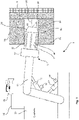
Fig. 1 illustrates a schematic of an exemplary robotic drill system; -
Figs. 2(a) to 2(f) illustrates a sequence of a tool head of the robotic drill system inserting into a hole of a drill template; -
Fig. 2(a) illustrates binding of the tool head during insertion in the initial insertion trajectory; -
Fig. 2(b) illustrates activating the self-centering device at the tool head, such as expanding theexpandable collet 7; -
Fig. 2(c) illustrates the tool head reoriented to a corrected alignment due to activation of the self-centering device; -
Fig. 2(d) illustrates the tool head at a corrected alignment with the self-centering device deactivated; -
Fig. 2(e) illustrates inserting the tool head along an update insertion trajectory; -
Fig. 2(f) illustrates activating the self-centering device to secure the tool head to the hole and activating theend effector 9; -
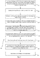
Fig. 3 is a flow diagram of an exemplary method of drilling with a robotic drill system; -
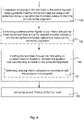
Fig. 4 is a flow diagram of additional steps in the method of drilling, including computing updated control signals to insert the tool head along an updated insertion trajectory; -
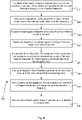
Fig. 5 is a flow diagram of additional steps in the method of drilling, including securing the tool head to the hole of the drill template; -
Fig. 6 is a flow diagram of an exemplary computer-implemented method of controlling a robotic drill system; -
Fig. 7(a) illustrates an end view of the tool head in the retracted configuration; and -
Fig. 7(b) illustrates an end view of the tool head in the expanded configuration. -
Fig. 1 illustrates an example of a robotic drill system 1 to activate anend effector 9 at awork piece 8.Fig. 3 illustrates amethod 100 of drilling with the robotic drill system 1 which is exemplified by the sequence illustrated inFigs. 2a to 2(f) . - The robotic drill system 1 is used with a
drill template 23 having one ormore holes 21 that correspond to location(s) for anend effector 9 of atool head 5 to perform operations on thework piece 8. Thedrill template 23 is used as a jig to guide thetool head 5 to the work piece. - The robotic drill system 1 includes a
robotic manipulator arm 15 to support atool head 5. One or morerobotic actuators 17 are provided to move the robotic manipulator arm to causerobotic insertion 110 of thetool head 5 towards thehole 21 of thedrill template 23. - The
tool head 5 includes a selectively activated self-centering device 41 and anend effector 9. In some particular examples, the self-centering device 41 is anexpandable collet 7 that is configured to expand between a retractedconfiguration 11 for insertion into thehole 21 and an expandedconfiguration 13. Theend effector 9 performs operations on thework piece 8 and can, for example, include a drill bit, a cutting tool, or other tool head. - The robotic drill system 1 also includes at least one
sensor 19 to detect binding of thetool head 5 within thehole 21 of thedrill template 23. This can include sensing (120) binding of at least part of the self-centering device 41 orexpandable collet 7 to thehole 21. - If binding is detected during robotic insertion of the
tool head 5 towards thehole 21, the robotic drill system 1, in response, stops robotic insertion. The self-centering device is activated 130 to correct the alignment of thetool head 5. In some examples of theexpandable collet 7, this includes expanding the diameter of theexpandable collet 7 towards the wall 2 of thehole 21. In this expandedconfiguration 13, theexpandable collet 7 centers the tool head 3 and theend effector 9 in thehole 21. - Subsequent to correcting the alignment of the
tool head 5, the robotic manipulator arm can insert 140 thetool head 5 into thehole 21 along an updated trajectory that is based on the correctedalignment 43. This enables thetool head 5 to be inserted into a desiredspecified position 47 where theend effector 9 can be activated 150 to perform operations on thework piece 8. - The robotic drill system 1 and
method 100 enables accurate placement of theend effector 9 in thedrill template 23. In particular, using the self-centering device 41, such as anexpandable collet 7, to correct alignment of thetool head 5. This can be advantageous for systems using utilizing lower precision sensors and components that have difficulties precisely locating atool head 5 with the negative result of thetool head 5 binding to thetemplate 23. - A detailed example of components of the robotic drill system 1 will now be described:
- Referring to
Figs. 1 ,7(a) and 7(b) , thetool head 5 includes anend effector 9 to perform operations on thework piece 8 and a self-centeringdevice 41 to correct the alignment of theend effector 9. - The
tool head 5 may include other components, such as thesensors 19 to detect binding,collet sensors 53 to detect forces at self-centeringdevice 41, and actuators to drive theend effector 9. - The
end effector 9 performs operation on thework piece 8. This can include a subtractive manufacturing operation (a.k.a. deductive manufacturing operation). In some examples, theend effector 9 includes a drill with a drill bit. The end effector may include, or be associated with a rotary actuator such as a motor, to selectively rotate the drill bit to drill into thework piece 8. - In some examples, at least part of the
end effector 9 is linearly extendible relative to other portions of the tool head 3 (such as the expandable collet 7) along atool head axis 49. This can assist in drilling whilst maintaining a remaining portion of thetool head 5 stationary. - The self-centering
device 41 is configured to center theend effector 9 in the center of the hole 21 (which includes aligning theend effector 9 in the hole 21). This can be achieve with the self-centeringdevice 41 of thetool head 5 imparting forces against thewall 22 of thehole 22 such that the relative position of theend effector 9 is centered with thehole 21. - In some examples, the self-centering
device 41 includes anexpandable collet 7 where the outer diameter of theexpandable collet 7 is selectively adjustable (which will be described in further detail below). In other examples, the self-centeringdevice 41 includes a plurality of radially extendable arms, whereby the selective distance between the distal ends of each extendable arm to a center are synchronized. It is to be appreciated that other centering devices may be adapted to center theend effector 9. - In the illustrated example shown in
Figs. 1 ,2 ,7(a) and 7(b) , the self-centeringdevice 41 can be in the form of anexpandable collet 7 that is configured to expand between a retractedconfiguration 11 during insertion into the hole, and an expandedconfiguration 13 to center theend effector 9 in thehole 21. - The expandable collet may have an outer surface that this cylindrical or substantially cylindrical so that in the expanded configuration 13 (which will be close to or same as the template hole diameter), the outer surface is in even or substantially even contact with the corresponding
cylindrical wall 22 of thehole 21. It is to be appreciated that the outer surface may have some slots to facilitate the expansion and retraction of thecollet 7. - In some examples, the retracted
diameter 27 of theexpandable collet 7 is at least 95%, but less than 100%, of the template hole diameter of thehole 21. In some examples, the retracteddiameter 27 of theexpandable collet 7 is in the range of 95% to 97% of the template hole diameter. In some other examples, the retracteddiameter 27 of theexpandable collet 7 is in the range of 97% to 99% of the template hole diameter. In some further examples, the retracteddiameter 27 of the expandable collet is in the range of at least 99% but less than 100% of the template hole diameter. - The expanded
configuration 13 of theexpandable collet 7 may include an expandeddiameter 28 that is at, or approximately 100% of the anticipated template hole diameter. This can provide a tight and precise fit so that there is confidence that theend effector 9 is centered and correctly aligned with thehole 21. - In some further examples, the
expandable collet 7 is configured to enable the expandable collet to have an unconstrained expandeddiameter 28 to be greater than the anticipated template hole diameter. This enables theexpandable collet 7 to expand towards a greater expandeddiameter 28 to tightly fit theexpandable collet 7, and therespective tool head 5, in thehole 21 of thedrill template 23. This can be useful for a further function of securing thetool head 5 in thehole 21 during activation of theend effector 9. - In some examples, a
collet sensor 53 is configured to output a collet sensor output that is indicative of force between theexpandable collet 7 and the wall of thehole 21. When expanding toward the expanded configuration, the diameter of theexpandable collet 7 is expanded until the collet sensor output achieves or exceeds a threshold value. This can be useful for limiting the amount of expansion of theexpandable collet 7 to prevent damage to thedrill template 23. The collet sensor output may also be used as an indicator that the expandable collet is in tight fit and secured to thehole 21. - In some examples, the
expandable collet 7 is configured to expand and retract with a pneumatic system. This may include using pneumatic actuators to expand theexpandable collet 7. In some examples, specifying or otherwise controlling pressure in a pneumatic cylinder of the pneumatic system controls the force that theexpandable collet 7 imparts to the wall of thehole 21 of thedrill template 23. - The
robotic manipulator arm 15 is configured to insert at least part of thetool head 5 into thehole 21 of thedrill template 23, which can be considered as a peg-in-hole movement. To aid insertion of thetool head 5, thetool head 5 may include a lead-inchamfer 29. The lead-inchamfer 29 that includes a lead-inedge 31, where the lead-in edge has a lead-in diameter 34 that is less than the retracteddiameter 27 of theexpandable collet 7. In some examples, the lead-in diameter is at least 75% of a template hole diameter of thehole 21. In other examples, the lead-in diameter is at least 80% of the template hole diameter. In yet further examples, the lead-in diameter is at least 90% of the template hole diameter. In other examples, the lead-in diameter is at least 95% of the template hole diameter. - In some examples, the lead-in chamfer includes a frustoconical-shaped portion.
- The
robotic manipulator arm 15 can articulate in multiple degrees of freedom. In some examples, this can include arobotic manipulator arm 15 that can translate thetool head 5 in an x, y, and z axis. Therobotic manipulator arm 15 may also rotate thetool head 5 around a respective x, y, and z axis. - The
robotic manipulator arm 15 is moved by one or more robotic actuator(s) 17. Therobotic actuators 17 may include linear or rotary motors, pneumatic actuators, hydraulic actuators, or combinations thereof. - The
robotic manipulator arm 15, in conjunction with sensors and acontroller 30, may be configured to a drive mode or a freedrive mode. In a drive mode, thecontroller 30 receives instructions to move the manipulator arm to cause insertion of the tool head, and in response sends control signals to selectively activate one or more of therobotic actuators 17 to effect that insertion motion. The drive mode may also be used for other desired movements of the robotic manipulator arm oftool head 5, such as retraction of thetool head 5 from thehole 21 and movement of thetool head 5 towards another hole of thedrill template 23. - The
robotic manipulator arm 15 may also be configured to a compliant freedrive mode (also known as "zero gravity" mode). In the compliant freedrive mode, therobotic manipulator arm 15 is configured to be freely repositionable to facilitate movement of the tool head. Therobotic manipulator arm 15 and displace (include translation and rotation) based on external forces applied to therobotic manipulator arm 15 ortool head 5. This can include sensors in the robotic manipulator arm detecting external forces to components of therobotic manipulator arm 15 and actuating therobotic actuators 17 to follow the forces and/or movements. - The compliant freedrive mode enables the
tool head 5 and endeffector 9 to move to the correctedalignment 43 of thetool head axis 49 relative to thehole 21 by forces generated when the self-centeringdevice 41 is activated. - The robotic drill system 1 includes one or
more sensors expandable collet 7 to thehole 21. In some examples, thesensor 19 may be similar to, or the same as, thecollet sensor 53 that detects forces directed to theexpandable collet 7. - In other examples,
sensors tool head 5 to the wall of the hole. For example, measuring forces on other parts of therobotic manipulator arm 15 or metrics associated with therobotic actuators 17. - In some examples, the
sensors 19 may include a sensor to detect change in current, voltage and/or heat at the at least onerobotic actuator 17. This can be used to infer forces resistance of movement at thetool head 5 that is indicative of binding. - In some examples, the
sensors 19 include a force sensor to detect at least one force at thetool head 5,expandable collet 7,robotic actuator 17,robotic manipulator arm 15, or thedrill template 23. In some examples, the force sensor may be a magnitude based sensor to detect forces. In some examples, this can be based on a lower cost sensor that detects force in any direction (in contrast to a higher cost sensor that detects force(s) in specific component directions). - In some examples, the
sensors 19 may include an accelerometer to detect changes in acceleration of thecollet 7 or thetool head 5. - In some examples, the sensor detects changes in electrical continuity or capacitance between the
collet 7 ortool head 5 and thedrill template 23. - In some examples, the tool head 3 is provided with a tool head sensor to detect that the tool head 3 has been inserted to a specified position (such as a proper depth of the tool head 3 in the
hole 21 of the drill template 23). This can included an inductive sensor to detect the presence of ferrous metals. In some examples, thedrill template 23 includes ferrous metals, whereby the inductive sensor provides an output based on detecting proximity to the ferrous metals of thedrill template 23. This can be used as part of an interlock system for theend effector 9, whereby theend effector 9 can only be selectively activated if the inductive sensors provide an output indicative of the tool head 3 at a specified position. In some examples, the specified position may include a range of distance between the tool head sensor at the tool head and thedrill template 23. In some examples, the range may include 1 to 2 mm between the tool head sensor and thedrill template 23. - In other examples, the tool head may be provided with optical range sensors to provide an output indicative of relative distance between the tool head 3 and the drill template. This can be used to determine if the tool head 3 has advanced to a specified depth in the
hole 21 of thedrill template 23. - The
sensors 19 of the robotic drill system 1 may also include position sensors to send position sensor signals that is indicative of position and/or alignment of thetool head 5. This can include determining the position and/or alignment of the tool head at the corrected alignment. In some examples, this can include rotary encoders associated with therobotic manipulator arm 15,robotic actuators 17, and tool head 3. This information, that can include relative information of the position and/or alignment of thetool head 5 relative to the robotic drill system 1, can be used by the controller to calculate the updated insertion trajectory. - The robotic drill system 1 may include a
limited granularity sensor 33 to provide limited granularity sensor feedback signals 35 to guide insertion of thetool head 5 towards thehole 21 along the initial insertion trajectory. - In some examples, the
limited granularity sensor 33 is a camera. The limited granularitysensor feedback signal 35 may include images (or video) of the tool head 5 (or other components of the robotic manipulator arm 15) relative to thehole 21 of thedrill template 23. This information can be used by thecontroller 30 to determine aninitial insertion trajectory 37 that is close enough to initially insert part of thetool head 5 into thehole 21. After initial insertion, and if the accuracy provided by the limited granularity sensor is insufficient for precise placement of thetool head 5 into thehole 21, the above mentioned method of using the self-centeringdevice 41 is used to correct the alignment of thetool head 5. - In some examples, the
limited granularity sensor 33 includes a depth camera with depth sensing capabilities. For example a system with multiple cameras to provide stereo depth data. In other examples, thelimited granularity sensor 33 includes coded light depth camera(s) that include projecting a light pattern and capturing the reflected light pattern to determine depth. - The advantage of using a
limited granularity sensor 33, such as a video camera, is the low cost. The video camera is also adaptable in that it can be configured to have a wide field of view to allow operations on alarge drill template 23 andwork piece 8. This also enables a robotic drill system 1 that can be movable and easily set up and initialized. This can be in contrast with systems that rely on expensive laser scanners that require precise alignment and calibration of components. - A
controller 30 may include one or more processors to execute computer-readable program code stored on a non-transitory computer-readable storage medium. The controller may include a computer, a computer system, or distributed computer system on a network. In other examples, thecontroller 30 can include a microcontroller, including a reduced instruction set computer. - The
controller 30 is configured to execute program instruction code to perform themethod 100 and control the robotic drill system 1. This can include receiving sensor signals fromsensors robotic actuators 17, the self-centeringdevice 41, and endeffector 9.Controller 30 can also be used to compute control signals and insertion trajectories for the robotic drill system 1. An example of this is the execution of program code to cause a computer system to performmethod 200 illustrated inFig. 6 . - The
drill template 23 may be constructed of a stable and stiff material. This can include a material selected with minimal thermal expansion or contraction in the operating temperature range to minimize variance in the location of the hole(s) 21. In some examples, thedrill template 23 may be constructed of metal alloys. In some examples, thedrill template 23 is constructed of a ferrous metal or ally, or semi-ferrous alloy (such as a semi-ferrous aluminum alloy). - The
work piece 8 may include a variety of solid materials that require drilling. This can include composite materials (e.g. fiber reinforced plastics), metal alloys, wood etc. In some examples, thework piece 8 may be a component of an aircraft. - During robotic drilling, the
drill template 23 is preferably located to thework piece 8 in a consistent manner. This may include mounting thedrill template 23 relative to thework piece 8. In some examples, this can include clamping thedrill template 23 to thework piece 8, fastening thedrill template 23 to the work piece, or otherwise locating thedrill template 23 to thework piece 8 with a jig. - A specific example of a
method 100 of robotic drilling will now be described with reference toFigs. 3 to 6 . The example will be described with reference to the corresponding sequence illustrated inFigs. 2(a) to 2(f) . - The method includes the
controller 30computing 210 initial control signals torobotic actuators 17 for inserting the tool head 3 towards thehole 21 of thedrill template 23 along aninitial insertion trajectory 37. This can include receiving from the limited granularity sensor feedback signals 35 the position and/or orientation of the tool head 3 relative to thehole 21 and calculating theinitial insertion trajectory 37 to place the tool head 3 into thehole 21. - The initial control signals are then sent 220 to the
robotic actuators 17 so that therobotic manipulator arm 15 can insert 110 the tool head 3 into thehole 21 along theinitial insertion trajectory 37. When inserting the tool head 3, theexpandable collet 7 is typically in a retractedconfiguration 11. - As the tool head 3 is inserted along the
initial insertion trajectory 37, there may be minor errors that cause the tool head 3 to be imprecisely aligned with thehole 21. These errors can be cause by errors in the sensors, calibration issues, errors in calculation, etc. As a result, the tool head 3 may enter the hole 21 (aided by the lead-in chamfer) and then bind to thewall 22 of thehole 21. This is best illustrated inFig. 2(a) where the tool head is inserted along theinitial insertion trajectory 37 that is off-axis to thehole axis 51. As a result, theexpandable collet 7 in the retractedconfiguration 11 contacts and binds to portions of thewall 22. - The
sensors 19sense 120 binding of the tool head 3 to thewall 22 and, in response, send sensor signals indicative of this state to thecontroller 30. Thecontroller 30 on receiving 230 these sensor signals, then determines 240 binding of the tool head to thewall 22. In response, the controller sends 250 control signals to stop 122 robotic insertion of thetool head 5 and activation control signals to activate 130 the self-centeringdevice 41 to reorient and reposition thetool head 5 to the correctedalignment 43. - To facilitate the repositioning movement to the corrected
alignment 43, the robotic drill system 1 may be switched 124 to the compliant freedrive mode to allow forces generated with activating 130 of the self-centeringdevice 41 move the tool head 3. In the example ofFig. 2(c) , activating the self-centering device includes expanding theexpandable collet 7 of thetool head 5 towards thewall 22 of thehole 21. To provide precise corrected alignment, this can include expanding theexpandable collet 7 until achieving a threshold value of force between theexpandable collet 7 and thewall 22. This can be determined based on the collet sensor outputs of thecollet sensor 53. - The corrected
alignment 43 may include placing the tool head 3 so that thetool head axis 49 is coaxial with thehole axis 51. This movement is best illustrated in the transition fromFigs. 2(b) and 2(c) where the expandable collet 7 (as the self-centering device 41), expands to an expanded configuration so that the cylindrical outer surface of theexpandable collet 7 is flush or substantially flush with thewall 22 of thehole 21. AtFig. 2(c) the tool head 3 is shown with a correctedalignment 43 where thetool head axis 49 is centered with thehole axis 51. - One or more self-centering device sensors (such as collet sensor 53) may detect that the tool head 3 is in the corrected
alignment 43 and send a corresponding self-centering device sensor output signal to thecontroller 30. On receiving 245 the sensor signal indicative of the corrected alignment, thecontroller 30 sends 246 a deactivation control signal to deactivate the self-centeringdevice 41. - At the tool head 3, the self-centering
device 41 is deactivated 134. As illustrated inFig. 2(d) , this can include configuring theexpandable collet 7 in a retractedconfiguration 11. - The next step is to proceed with further insertion of the tool head 3 into the
hole 21. To achieve this thecontroller 30 configures 132 therobotic manipulator arm 15 back to a drive mode so that selective activation of therobotic actuators 17 can cause further insertion of the tool head 3. - The
controller 30 is also configured to compute 260, based on the correctedalignment 43, an updatedinsertion trajectory 45. As illustrated inFigs. 4 and6 , this may include computing 136 the require control signals to advance the tool head 3 along the currenttool head axis 49 that is centered with thehole axis 51. To compute the corrected alignment, thecontroller 30 may receive 262 from one or more tool head position sensors, a position sensor output indicative of the position and/or alignment of the tool head 3 at the corrected alignment. Thecontroller 30 may then compute the updated insertion trajectory based, at least in part, on this received position sensor output. In some examples, this updated position sensor output can be used to recalibrate the robotic drill system 1. - The
controller 30 sends 270 updated control signals to selectively 142 activate therobotic actuators 17 to drive therobotic manipulator arm 15 so that the tool head 3 is inserted 140 into thehole 21 along the updatedinsertion trajectory 45. This is best illustrated inFig. 2(e) where the tool head 3, with the retractedexpandable collet 7, is inserted into thehole 21. - One or more
tool head sensors 55 detect the position or further movement of the tool head 3, during further advance along the updatedinsertion trajectory 45. The tool head sensor 55 (such as an inductive sensor or optical sensor described above) sends a tool head sensor signal indicative of thetool head 5 inserted 144 at a specified position in thehole 21. In some examples as illustrated inFig. 5 , this includes thetool head 5 achieving a specified depth within thehole 21. Thecontroller 30, in response to receiving 275 the tool head sensor signal indicative of thetool head 5 at the specifiedposition 47, then sends a control signal to stop 146 further activation of therobotic actuators 17 so that further insertion is stopped. Thecontroller 30 also sends 276 an activation control signal to activate 148 the self-centeringdevice 41 of the tool head to secure the tool head 3 at the specified position relative to thehole 21. - In some examples, expanding the
expandable collet 7 can draw the tool head 3 to move further into thehole 21 of thedrill template 23. In other examples, expanding theexpandable collet 7 can cause the tool head 3 to slightly withdraw away from thehole 21 of thedrill template 23. It is to be appreciated that the specified position can be offset to compensate for such movements so that theend effector 9 located at a desired relative position in thehole 21 during activation. - In response to the tool head 3 secured at the specified position, the
controller 30 further sends 280 an end effector control signal to activate 150 theend effector 9 of the tool head 3. - This is best illustrated in
Fig. 2(f) where theexpandable collet 7 is in the expandedconfiguration 13 to secure the tool head 3 to thewall 22 of thehole 21, theend effector 9 is activated to drill a hole in thework piece 8. This can include theend effector 9 further advancing forward through thetool head axis 49 relative to theexpandable collet 7 secured to thehole 21. - Once operation of the
end effector 9 in the hole is performed, the robotic drill system 1 can withdraw the tool head 3 from thehole 21 and proceed to insertion into another hole of the drill template to perform subsequent operations on thework piece 8. - The disclosure comprises examples in accordance with the following clauses:
- Clause 1. A robotic drill system (1) comprising: a tool head (5) comprising an expandable collet (7) and an end effector (9), wherein the expandable collet (7) is configured to expand between a retracted configuration (11) for insertion into a hole (21) of a drill template (23) and an expanded configuration (13); a robotic manipulator arm (15) to support the tool head (5); at least one robotic actuator (17) to move the robotic manipulator arm (15) for causing robotic insertion of the tool head (5) towards a hole (21) of a drill template (23); at least one sensor (19) to detect binding of the expandable collet (7) within the hole (21) of the drill template (23), wherein in response to detecting binding of the expandable collet (7) within the hole (21), robotic insertion of the tool head (5) is stopped and the expandable collet (7) is configured to expand to the expanded configuration (13) to center the end effector (9) in the hole (21), and wherein a retracted diameter (27) of the expandable collet (7) in the retracted configuration (11) is at least 95%, but less than 100%, of a template hole diameter of the hole (21).
- Clause 2. A robotic drill system (1) according to Clause 1, wherein in response to detecting binding of the expandable collet (7) within the hole (21), robotic insertion is stopped and the robotic manipulator arm (15) and at least one actuator (17) are switched to a compliant freedrive mode in which the robotic manipulator arm is freely repositionable to a corrected alignment relative to the hole by forces generated with expanding (130) the expandable collet (7) of the tool head (5).
- Clause 3. A robotic drill system (1) according to either Clause 1 or 2, further comprising: a limited granularity sensor (33) to provide limited granularity sensor feedback signals (35) to guide insertion of the tool head (5) towards the hole (21) along an initial insertion trajectory (37).
- Clause 4. A robotic drill system (1) according to Clause 3 wherein the limited granularity sensor (33) is a video camera or depth camera system.
-
Clause 5. A robotic drill system (1) according to any of Clauses 1 to 4, wherein the retracted diameter (27) is in the range of at least one of: (i) 95% to 97% of the template hole diameter; (ii) 97% to 99% of the template hole diameter; or (iii) at least 99% but less than 100% of the template hole diameter. - Clause 6. A robotic drill system (1) according to any of Clauses 1 to 5 wherein the tool head (5) includes a lead-in chamfer (29) to aid insertion of the tool head (5) into the hole (21), wherein the lead-in-chamfer (29) includes a lead-in edge (31) with a lead-in diameter (34) that is less than the retracted diameter (27) and at least 75% of the template hole diameter.
-
Clause 7. A robotic drill system (1) according to any one of Clauses 1 to 6, wherein the at least one sensor (19) to detect binding comprise one or more of: a sensor to detect change in current, voltage and/or heat at the at least one robotic actuator (17); a force sensor to detect at least one force at one or more of the tool head (5), collet (7), robotic actuator (17), or the drill template (23); an accelerometer to detect changes in acceleration of the collet (7) or tool head (5); and a sensor to detect changes in electrical continuity or capacitance between the collet (7) or tool head (5) and the drill template (23). -
Clause 8. A robotic drill system (1) according to any one of Clauses 1 to 7 further comprising: a collet sensor (53) to output a collet sensor output that is indicative of force between the expandable collet (7) and a wall (22) of the hole (21), wherein to configure the expandable collet (7) to the expanded configuration (13) includes expanding the diameter of the expandable collet (7) until the collet sensor output achieves or exceeds a threshold value. -
Clause 9. A method of drilling with a robotic drill system (1) comprising: inserting (110) a tool head (5) of the robotic drill (3) within a hole (21) of a drill template (23) along an initial insertion trajectory (37) with a robotic manipulator arm (15) that is moved by at least one robotic actuator (17) for causing robotic insertion of the tool head (5); sensing (120) binding of the tool head to a wall (22) of the hole (21); in response to binding of the tool head (5) to a wall (22) of the hole (21) while inserting the tool head (5) along the initial insertion trajectory (37), stopping (122) robotic insertion of the tool head (5) and activating (130) a self-centering device (41) of the tool head (5) to reorient the tool head (5) to a corrected alignment (43) of the tool head axis (49) relative to the hole (21); inserting (140) the tool head into the hole (21) along an updated insertion trajectory (45), wherein the updated insertion trajectory is based on the corrected alignment (43); and activating (150) an end effector (9) of the tool head (5). -
Clause 10. A method of drilling according toClause 9, wherein in response to binding of the tool head (5) to the wall (22), the method further comprises: stopping (122) robotic insertion of the tool head (5) towards the hole (21) along the initial insertion trajectory (37): switching (124) the robotic manipulator arm to a compliant freedrive mode to facilitate repositioning movement of the tool head (5) to the corrected alignment (43) of the tool head axis (49) relative to the hole (21) by forces generated with activating (130) the self-centering device (41) of the tool head (5), and wherein subsequent to activating the self-centering device (41) of the tool head (5) to reposition the tool head (5) to the corrected alignment relative to the hole (21), the method further comprises: configuring (132) the robotic manipulator arm (15) to a drive mode whereby selective activation of at least one robotic actuator (17) moves the robotic manipulator arm (15) for causing robotic insertion of the tool head (5); and deactivating (134) the self-centering device of the tool head. -
Clause 11. A method according toClause 10 , wherein subsequent to activating (130) the self-centering device of the tool head to reposition the tool head (5) to the corrected alignment relative to the hole (21), the method further comprises: computing (136) updated control signals for inserting the tool head (5) along the updated insertion trajectory (45); and wherein inserting (140) the tool head into the hole along the updated insertion trajectory comprises: selectively (142) activating the robotic actuator (17) in accordance with the updated control signals. - Clause 12. A method of drilling according to
Clause 11, wherein inserting the tool head (5) into the hole (21) along an updated insertion trajectory (45) further comprises: inserting (144) the tool head (5) to a specified position (47); and in response to the tool head positioned at the specified position (47), the method further comprises: stopping (146) selective activation of the robotic actuator (17); and activating (148) the self-centering device (41) of the tool head (5) to secure the tool head (5) at the specified position (47) when activating the end effector (9) of the tool head (5). -
Clause 13. A method of drilling according to any one ofClauses 9 to 12 wherein the corrected alignment (43) of the tool head (5) relative to the hole (21) includes: centering a tool head axis (49) of the tool head (5) with a hole axis (51) of the hole (21). - Clause 14. A method according to any one of
Clauses 9 to 13 wherein sensing (120) binding of the tool head (5) to a wall (22) of the hole (22) comprises one or more of: detecting force at one or more of the self-centering device (41), tool head (5), robotic actuators (17) of the robotic drill (3) or drill template (23); detecting changes in electrical continuity or capacitance between the self-centering device (41) or tool head (5) and the drill template; detecting change in acceleration of the self-centering device (41) or tool head (5); detecting changes in current, voltage, heat at actuators or other components of the robotic drill (3). -
Clause 15. A method according to any one ofClauses 9 to 14 wherein activating (130, 148) the self-centering device of the tool head (5) comprising expanding a collet (7) of the tool head (5) towards a wall (22) of the hole (21). - Clause 16. A method according to
Clause 15, wherein activating (130, 148) the self-centering device comprises expanding the collet (7) of the tool head (5) until achieving or exceeding a threshold value of force between the collet (7) and the wall (22). -
Clause 17. A non-transitory computer-readable storage medium that has computer-readable program code stored therein that, when executed by a processor, causes a computer system to at least: compute (210) initial control signals to robotic actuators (17) for inserting a tool head of the robotic drill towards a hole of a drill template along an initial insertion trajectory; send (220) control signals to robotic actuators to insert the tool head towards the hole along the initial insertion trajectory; receive (230) sensor signals indicative of binding of the tool head (5) to a wall (22) of the hole (21); determine (240), based on the sensor signals, binding of the tool head to the wall (22) of the hole (21), and in response, send (250) an activation control signal to activate a self-centering device (41) of the tool head (5) to reposition the tool head to a corrected alignment relative to the hole; compute (260), based on the corrected alignment of the tool head (5) relative to the hole, an updated insertion trajectory; send (270) updated control signals to robotic actuators to insert the tool head towards the hole along the updated insertion trajectory; and send (280) an end effector control signal to activate an end effector of the tool head. - Clause 18. A non-transitory computer-readable storage medium according to
Clause 17, when executed by a processor, causes at computer system to further: receive (262), from one or more position sensors, position sensor signals indicative of position and/or alignment of the tool head at the corrected alignment, wherein to compute (260) an updated insertion trajectory includes the system to compute an updated insertion trajectory based on the position sensor signals of the tool head at the corrected alignment. -
Clause 19. A non-transitory computer-readable storage medium according to Clause 18, wherein at the corrected alignment, a tool head axis (49) is centered with a hole axis (51) of the hole, and wherein to compute (260) an updated insertion trajectory (260) includes the system to compute an updated insertion trajectory along the tool head axis (49) of the centered tool head (5). - Clause 20. A non-transitory computer-readable storage medium according to any one of
Clauses 17 to 19, wherein to compute (210) initial control signals to robotic actuators (17) comprises the computer system to: receive , from a limited granularity sensor (33), limited granularity sensor feedback signals (35) on the position or orientation of the tool head (5) relative to the hole (21) of the drill template (23); wherein the initial control signals are, at least in part, based on the limited granularity sensor feedback signals (35). -
Clause 21. A non-transitory computer-readable storage medium according to any one ofClauses 17 to 20, when executed by the processor, causes the computer system to further: receive (245), from a self-centering device sensor (53), a self-centering device sensor output indicative of the tool head (5) in the corrected alignment (43) relative to the hole (21), and in response to receiving the self-centering device sensor output indicative of the tool head (5) in the corrected alignment (43), sending (246) a deactivation control signal to deactivate the self-centering device (41) of the tool head (5). -
Clause 22. A non-transitory computer-readable storage medium according to any one ofClauses 17 to 21, when executed by the processor, causes the computer system to further: receive (275), from a tool head sensor (55), a tool head sensor signal indicative of the tool head (5) at a specified position (47) in the hole (21); in response to the tool head positioned at the specified position, send (276) a activation control signal to activate the self-centering device (41) of the tool head to secure the tool head at the specified position relative to the hole (21), wherein in response to the tool head secured at the specified position relative to the hole, the computer system is caused to send (280) the end effector control signal to activate the end effector of the tool head. - The disclosure set forth above may encompass multiple distinct examples with independent utility. Although each of these has been disclosed in its preferred form(s), the specific examples thereof as disclosed and illustrated herein are not to be considered in a limiting sense, because numerous variations are possible. To the extent that section headings are used within this disclosure, such headings are for organizational purposes only. The subject matter of the disclosure includes all novel and nonobvious combinations and subcombinations of the various elements, features, functions, and/or properties disclosed herein. The following claims particularly point out certain combinations and subcombinations regarded as novel and nonobvious. Other combinations and subcombinations of features, functions, elements, and/or properties may be claimed in applications claiming priority from this or a related application. Such claims, whether broader, narrower, equal, or different in scope to the original claims, also are regarded as included within the subject matter of the present disclosure.
- It will be appreciated by persons skilled in the art that numerous variations and/or modifications may be made to the above-described examples, without departing from the broad general scope of the present disclosure. The present examples are, therefore, to be considered in all respects as illustrative and not restrictive.
Claims (15)
- A robotic drill system (1) comprising:- a tool head (5) comprising an expandable collet (7) and an end effector (9), wherein the expandable collet (7) is configured to expand between a retracted configuration (11) for insertion into a hole (21) of a drill template (23) and an expanded configuration (13);- a robotic manipulator arm (15) configured to support the tool head (5);- at least one robotic actuator (17) configured to move the robotic manipulator arm (15) for causing robotic insertion of the tool head (5) towards the hole (21) of the drill template (23); and- at least one sensor (19) configured to detect binding of the expandable collet (7) within the hole (21) of the drill template (23), andwherein in response to detecting binding of the expandable collet (7) within the hole (21), the robotic drill system (1) is configured to stop robotic insertion of the tool head (5) and to expand the expandable collet (7) to the expanded configuration (13) to center the end effector (9) in the hole (21), and
wherein a retracted diameter (27) of the expandable collet (7) in the retracted configuration (11) is at least 95%, but less than 100%, of a template hole diameter of the hole (21). - A robotic drill system (1) according to claim 1 wherein, in response to detecting binding of the expandable collet (7) within the hole (21), the robotic drill system (1) is configured to stop robotic insertion and to switch (124) the robotic manipulator arm (15) and at least one robotic actuator (17) to a compliant freedrive mode in which the robotic manipulator arm (15) is freely repositionable to a corrected alignment (43) relative to the hole (21) by forces generated with expanding (130) the expandable collet (7) of the tool head (5).
- A robotic drill system (1) according to either claim 1 or 2, further comprising:- a limited granularity sensor (33) configured to provide limited granularity sensor feedback signals (35) to guide insertion of the tool head (5) towards the hole (21) along an initial insertion trajectory (37); and, optionally, wherein the limited granularity sensor (33) is a video camera or a depth camera system.
- A robotic drill system (1) according to any of claims 1 to 3, wherein the retracted diameter (27) is in the range of at least one of:(i) 95% to 97% of the template hole diameter;(ii) 97% to 99% of the template hole diameter; or(iii) at least 99% but less than 100% of the template hole diameter.
- A robotic drill system (1) according to any of claims 1 to 4 wherein the tool head (5) includes a lead-in chamfer (29) to aid insertion of the tool head (5) into the hole (21), wherein the lead-in chamfer (29) includes a lead-in edge (31) with a lead-in diameter (34) that is less than the retracted diameter (27) and at least 75% of the template hole diameter.
- A robotic drill system (1) according to any one of claims 1 to 5, wherein the at least one sensor (19) configured to detect binding comprise one or more of:a sensor to detect change in current, voltage and/or heat at the at least one robotic actuator (17);a force sensor configured to detect at least one force at one or more of the tool head (5), collet (7), robotic actuator (17), or the drill template (23);an accelerometer configured to detect changes in acceleration of the collet (7) or tool head (5); anda sensor configured to detect changes in electrical continuity or capacitance between the collet (7) or tool head (5) and the drill template (23).
- A robotic drill system (1) according to any one of claims 1 to 6 further comprising:a collet sensor (53) configured to output a collet sensor output that is indicative of force between the expandable collet (7) and a wall (22) of the hole (21),wherein to configure the expandable collet (7) to the expanded configuration (13) includes expanding the diameter of the expandable collet (7) until the collet sensor output achieves or exceeds a threshold value.
- A method (100, 200) of aligning a robotic drill system (1) comprising:- inserting a tool head (5) of the robotic drill (1) within a hole (21) of a drill template (23) along an initial insertion trajectory (37) with a robotic manipulator arm (15) that is moved by at least one robotic actuator (17) for causing robotic insertion of the tool head (5);- sensing binding of the tool head (5) to a wall (22) of the hole (21);- in response to binding of the tool head (5) to a wall (22) of the hole (21) while inserting the tool head (5) along the initial insertion trajectory (37), stopping (122) robotic insertion of the tool head (5) and activating (130) a self-centering device (41) of the tool head (5) to reorient the tool head (5) to a corrected alignment (43) of the tool head (5) axis (49) relative to the hole (21);- inserting (140) the tool head (5) into the hole (21) along an updated insertion trajectory (45), wherein the updated insertion trajectory (45) is based on the corrected alignment (43); and- activating (150) an end effector (9) of the tool head (5).
- The method (100, 200) of claim 8 wherein, in response to binding of the tool head (5) to the wall (22), the method (100, 200) further comprises:- stopping (122) robotic insertion of the tool head (5) towards the hole (21) along the initial insertion trajectory (37):- switching (124) the robotic manipulator arm (15) to a compliant freedrive mode to facilitate repositioning movement of the tool head (5) to the corrected alignment (43) of the tool head axis (49) relative to the hole (21) by forces generated with activating (130) the self-centering device (41) of the tool head (5), andwherein, subsequent to activating (130) the self-centering device (41) of the tool head (5) to reposition the tool head (5) to the corrected alignment (43) relative to the hole (21), the method (100, 200) further comprises:- configuring (132) the robotic manipulator arm (15) to a drive mode whereby selective activation of at least one robotic actuator (17) moves the robotic manipulator arm (15) for causing robotic insertion of the tool head (5); and- deactivating (134) the self-centering device (41) of the tool head (5).
- The method (100, 200) of claim 9 wherein, subsequent to activating (130) the self-centering device (41) of the tool head (5) to reposition the tool head (5) to the corrected alignment (43) relative to the hole (21), the method (100, 200) further comprises:- computing (136) updated control signals for inserting the tool head (5) along the updated insertion trajectory (45); andwherein inserting the tool head (5) into the hole (21) along the updated insertion trajectory (45) comprises:
selectively activating (142) the at least one robotic actuator (17) in accordance with the updated control signals. - The method (100, 200) of claim 10, wherein inserting the tool head (5) into the hole (21) along an updated insertion trajectory (45) further comprises:- inserting the tool head (5) to a specified position (47); and- in response to the tool head (5) positioned at the specified position (47), the method (100, 200) further comprises:- stopping (146) selective activation of the at least one robotic actuator (17); and- activating (148) the self-centering device (41) of the tool head (5) to secure the tool head (5) at the specified position (47) when activating the end effector (9) of the tool head (5).
- The method (100, 200) of any one of claims 8 to 11 ,wherein the corrected alignment (43) of the tool head (5) relative to the hole (21) includes: centering a tool head axis (49) of the tool head (5) with a hole axis (51) of the hole (21).
- The method (100, 200) of any one of claims 8 to 12, wherein sensing binding of the tool head (5) to a wall (22) of the hole (21) comprises one or more of:- detecting force at one or more of the self-centering device (41), tool head (5), robotic actuators (17) of the robotic drill (1) or drill template (23);- detecting changes in electrical continuity or capacitance between the self-centering device (41) or tool head (5) and the drill template (23);- detecting change in acceleration of the self-centering device (41) or tool head (5); and- detecting changes in current, voltage, heat at actuators or other components of the robotic drill (1).
- The method (100, 200) of any one of claims 8 to 13, wherein activating (148) the self-centering device (41) of the tool head (5) comprises:
expanding a collet (7) of the tool head (5) towards a wall (22) of the hole (21) until achieving or exceeding a threshold value of force between the collet (7) and the wall (22). - A computer program comprising computer program instructions that, when executed by a computer processor, cause the computer processor to perform the method of any of claims 9 to 14, or a computer-readable medium having stored thereon such a computer program.
Applications Claiming Priority (1)
| Application Number | Priority Date | Filing Date | Title |
|---|---|---|---|
| US202163175781P | 2021-04-16 | 2021-04-16 |
Publications (1)
| Publication Number | Publication Date |
|---|---|
| EP4074444A1 true EP4074444A1 (en) | 2022-10-19 |
Family
ID=80928620
Family Applications (1)
| Application Number | Title | Priority Date | Filing Date |
|---|---|---|---|
| EP22163301.9A Pending EP4074444A1 (en) | 2021-04-16 | 2022-03-21 | Robotic drill system and method of drilling with a robotic drill system |
Country Status (4)
| Country | Link |
|---|---|
| US (1) | US12220751B2 (en) |
| EP (1) | EP4074444A1 (en) |
| JP (1) | JP2022164608A (en) |
| CN (1) | CN115213912A (en) |
Cited By (1)
| Publication number | Priority date | Publication date | Assignee | Title |
|---|---|---|---|---|
| DE102022134055A1 (en) * | 2022-12-20 | 2024-06-20 | Airbus Operations Gmbh | Method and device for positioning and aligning a tool |
Families Citing this family (8)
| Publication number | Priority date | Publication date | Assignee | Title |
|---|---|---|---|---|
| EP4646317A1 (en) * | 2023-01-06 | 2025-11-12 | BAE SYSTEMS plc | A tool engagement coupling system and associated method |
| EP4397453A1 (en) * | 2023-01-06 | 2024-07-10 | BAE SYSTEMS plc | A tool engagement coupling and associated method |
| JP2026501714A (en) * | 2023-01-06 | 2026-01-16 | ビ-エイイ- システムズ パブリック リミテッド カンパニ- | Tool-engagement coupling and related methods |
| EP4397454A1 (en) * | 2023-01-06 | 2024-07-10 | BAE SYSTEMS plc | A tool engagement coupling system and associated method |
| GB2629438B (en) * | 2023-04-28 | 2025-10-08 | Airbus Operations Ltd | Method of checking the accuracy of a drilling robot |
| US12366446B2 (en) | 2023-05-22 | 2025-07-22 | The Boeing Company | Systems and methods for evaluating a gap between structural components |
| US20250123168A1 (en) * | 2023-10-11 | 2025-04-17 | The Boeing Company | Systems and methods for identifying mis-aligned holes in structural components |
| CN118492458B (en) * | 2024-07-18 | 2024-10-15 | 山东力创模具股份有限公司 | A robot system for automatic drilling of tire molds and a control method thereof |
Citations (3)
| Publication number | Priority date | Publication date | Assignee | Title |
|---|---|---|---|---|
| DE202011052431U1 (en) * | 2011-12-22 | 2013-03-25 | Kuka Systems Gmbh | processing tool |
| WO2016081443A1 (en) * | 2014-11-18 | 2016-05-26 | Apex Brands, Inc. | System and method of robotic positioning of multiple tools |
| WO2019059825A1 (en) * | 2017-09-21 | 2019-03-28 | Novator Ab | A method and a system for working a workpiece |
Family Cites Families (7)
| Publication number | Priority date | Publication date | Assignee | Title |
|---|---|---|---|---|
| US3514116A (en) * | 1968-01-19 | 1970-05-26 | Davenport Machine Tool Co Inc | Expanding collet |
| DE502004008917D1 (en) * | 2004-08-26 | 2009-03-12 | Schunk Gmbh & Co Kg | Mandrel with internal clamping devices |
| FR2912672B1 (en) * | 2007-02-16 | 2009-05-15 | Airbus France Sa | METHOD FOR ASSEMBLING TWO ASSEMBLIES, SUCH AS AIRCRAFT FUSELAGE ASSEMBLIES |
| CN105980091B (en) * | 2014-02-14 | 2019-10-08 | 艾沛克斯品牌公司 | Apparatus for fastening and its application method |
| US9789549B2 (en) * | 2015-07-07 | 2017-10-17 | The Boeing Company | Robotic system and drilling end effector for robotic system |
| CN105583423A (en) * | 2016-01-26 | 2016-05-18 | 刘燕 | Quick and precise workpiece positioning device |
| ES2788274B2 (en) * | 2019-04-17 | 2022-07-21 | Loxin 2002 Sl | MACHINING HEAD WITH ACTIVE CORRECTION, OPERATION PROCEDURE AND USE |
-
2022
- 2022-01-11 US US17/572,843 patent/US12220751B2/en active Active
- 2022-03-21 EP EP22163301.9A patent/EP4074444A1/en active Pending
- 2022-03-24 CN CN202210293169.5A patent/CN115213912A/en active Pending
- 2022-04-13 JP JP2022066105A patent/JP2022164608A/en active Pending
Patent Citations (3)
| Publication number | Priority date | Publication date | Assignee | Title |
|---|---|---|---|---|
| DE202011052431U1 (en) * | 2011-12-22 | 2013-03-25 | Kuka Systems Gmbh | processing tool |
| WO2016081443A1 (en) * | 2014-11-18 | 2016-05-26 | Apex Brands, Inc. | System and method of robotic positioning of multiple tools |
| WO2019059825A1 (en) * | 2017-09-21 | 2019-03-28 | Novator Ab | A method and a system for working a workpiece |
Cited By (1)
| Publication number | Priority date | Publication date | Assignee | Title |
|---|---|---|---|---|
| DE102022134055A1 (en) * | 2022-12-20 | 2024-06-20 | Airbus Operations Gmbh | Method and device for positioning and aligning a tool |
Also Published As
| Publication number | Publication date |
|---|---|
| US12220751B2 (en) | 2025-02-11 |
| CN115213912A (en) | 2022-10-21 |
| JP2022164608A (en) | 2022-10-27 |
| US20220331975A1 (en) | 2022-10-20 |
Similar Documents
| Publication | Publication Date | Title |
|---|---|---|
| EP4074444A1 (en) | Robotic drill system and method of drilling with a robotic drill system | |
| US10286556B2 (en) | Method and apparatus for compliant robotic end-effector | |
| US10589394B2 (en) | Method and arrangement of introducing boreholes into a surface of a workpiece mounted in a stationary manner using a boring tool attached to an articulated-arm robot | |
| EP2927765B1 (en) | Drilling apparatus and method | |
| JP6267157B2 (en) | Production system with robot with position correction function | |
| JP2022164608A5 (en) | ||
| CN113195176B (en) | Manufacturing system and method | |
| CN101804470B (en) | Automatic hole-making system and method for wing-body docking | |
| EP2837472A2 (en) | Robot system, robot control apparatus, method for controlling robot | |
| WO2007003869A1 (en) | Program-controlled process | |
| US11351642B2 (en) | Automatic tool head placement and assembly apparatus for a boring machine | |
| US20180257230A1 (en) | Positioning device and positioning method of processing tool | |
| US11084123B2 (en) | Laser-etching and machine-vision positioning system | |
| CA2036344C (en) | Industrial robot control method and apparatus | |
| BR112017020764B1 (en) | WORKPIECE CONVEYOR DEVICE | |
| GB2616844A (en) | Robot guidance using multiple frames | |
| US7259535B1 (en) | Apparatus and method for situating a tool with respect to a work site on a workpiece | |
| US20230075185A1 (en) | Method and system for positioning a moveable robotic system | |
| JP4962757B2 (en) | Control method of space 3 degrees of freedom parallel mechanism and space 3 degrees of freedom parallel mechanism | |
| JP2025056964A (en) | ROBOT CONTROL METHOD, SYSTEM, PRODUCT MANUFACTURING METHOD, PROGRAM, AND RECORDING MEDIUM | |
| EP4397454A1 (en) | A tool engagement coupling system and associated method | |
| JPH02180580A (en) | Origin adjusting device for industrial robot | |
| KR20200059357A (en) | Precision machining device using robot arm and its operation method | |
| CN117444275A (en) | Wall climbing hole making device and normal positioning method thereof | |
| JPS59227377A (en) | Robot device |
Legal Events
| Date | Code | Title | Description |
|---|---|---|---|
| PUAI | Public reference made under article 153(3) epc to a published international application that has entered the european phase |
Free format text: ORIGINAL CODE: 0009012 |
|
| STAA | Information on the status of an ep patent application or granted ep patent |
Free format text: STATUS: THE APPLICATION HAS BEEN PUBLISHED |
|
| AK | Designated contracting states |
Kind code of ref document: A1 Designated state(s): AL AT BE BG CH CY CZ DE DK EE ES FI FR GB GR HR HU IE IS IT LI LT LU LV MC MK MT NL NO PL PT RO RS SE SI SK SM TR |
|
| RAP3 | Party data changed (applicant data changed or rights of an application transferred) |
Owner name: THE BOEING COMPANY |
|
| STAA | Information on the status of an ep patent application or granted ep patent |
Free format text: STATUS: REQUEST FOR EXAMINATION WAS MADE |
|
| 17P | Request for examination filed |
Effective date: 20230331 |
|
| RBV | Designated contracting states (corrected) |
Designated state(s): AL AT BE BG CH CY CZ DE DK EE ES FI FR GB GR HR HU IE IS IT LI LT LU LV MC MK MT NL NO PL PT RO RS SE SI SK SM TR |
|
| RIC1 | Information provided on ipc code assigned before grant |
Ipc: B23B 49/02 20060101AFI20251106BHEP Ipc: B23B 31/40 20060101ALI20251106BHEP Ipc: B25J 11/00 20060101ALI20251106BHEP Ipc: B23B 39/14 20060101ALI20251106BHEP Ipc: B25J 9/16 20060101ALI20251106BHEP Ipc: B25J 13/08 20060101ALI20251106BHEP |
|
| GRAP | Despatch of communication of intention to grant a patent |
Free format text: ORIGINAL CODE: EPIDOSNIGR1 |
|
| STAA | Information on the status of an ep patent application or granted ep patent |
Free format text: STATUS: GRANT OF PATENT IS INTENDED |
|
| INTG | Intention to grant announced |
Effective date: 20251223 |
|
| P01 | Opt-out of the competence of the unified patent court (upc) registered |
Free format text: CASE NUMBER: UPC_APP_0000026_4074444/2026 Effective date: 20260102 |
|
| GRAJ | Information related to disapproval of communication of intention to grant by the applicant or resumption of examination proceedings by the epo deleted |
Free format text: ORIGINAL CODE: EPIDOSDIGR1 |
|
| STAA | Information on the status of an ep patent application or granted ep patent |
Free format text: STATUS: REQUEST FOR EXAMINATION WAS MADE |