EP4074413A1 - Fluidized bed reactor, and method for recovering active metal of lithium secondary battery utilizing same - Google Patents
Fluidized bed reactor, and method for recovering active metal of lithium secondary battery utilizing same Download PDFInfo
- Publication number
- EP4074413A1 EP4074413A1 EP20907225.5A EP20907225A EP4074413A1 EP 4074413 A1 EP4074413 A1 EP 4074413A1 EP 20907225 A EP20907225 A EP 20907225A EP 4074413 A1 EP4074413 A1 EP 4074413A1
- Authority
- EP
- European Patent Office
- Prior art keywords
- injection
- injection hole
- fluidized bed
- bed reactor
- lithium
- Prior art date
- Legal status (The legal status is an assumption and is not a legal conclusion. Google has not performed a legal analysis and makes no representation as to the accuracy of the status listed.)
- Pending
Links
Images


Classifications
-
- B—PERFORMING OPERATIONS; TRANSPORTING
- B01—PHYSICAL OR CHEMICAL PROCESSES OR APPARATUS IN GENERAL
- B01J—CHEMICAL OR PHYSICAL PROCESSES, e.g. CATALYSIS OR COLLOID CHEMISTRY; THEIR RELEVANT APPARATUS
- B01J8/00—Chemical or physical processes in general, conducted in the presence of fluids and solid particles; Apparatus for such processes
- B01J8/0015—Feeding of the particles in the reactor; Evacuation of the particles out of the reactor
- B01J8/004—Feeding of the particles in the reactor; Evacuation of the particles out of the reactor by means of a nozzle
-
- B—PERFORMING OPERATIONS; TRANSPORTING
- B01—PHYSICAL OR CHEMICAL PROCESSES OR APPARATUS IN GENERAL
- B01J—CHEMICAL OR PHYSICAL PROCESSES, e.g. CATALYSIS OR COLLOID CHEMISTRY; THEIR RELEVANT APPARATUS
- B01J8/00—Chemical or physical processes in general, conducted in the presence of fluids and solid particles; Apparatus for such processes
- B01J8/18—Chemical or physical processes in general, conducted in the presence of fluids and solid particles; Apparatus for such processes with fluidised particles
- B01J8/1818—Feeding of the fluidising gas
- B01J8/1827—Feeding of the fluidising gas the fluidising gas being a reactant
-
- B—PERFORMING OPERATIONS; TRANSPORTING
- B01—PHYSICAL OR CHEMICAL PROCESSES OR APPARATUS IN GENERAL
- B01J—CHEMICAL OR PHYSICAL PROCESSES, e.g. CATALYSIS OR COLLOID CHEMISTRY; THEIR RELEVANT APPARATUS
- B01J8/00—Chemical or physical processes in general, conducted in the presence of fluids and solid particles; Apparatus for such processes
- B01J8/18—Chemical or physical processes in general, conducted in the presence of fluids and solid particles; Apparatus for such processes with fluidised particles
- B01J8/1872—Details of the fluidised bed reactor
-
- B—PERFORMING OPERATIONS; TRANSPORTING
- B01—PHYSICAL OR CHEMICAL PROCESSES OR APPARATUS IN GENERAL
- B01J—CHEMICAL OR PHYSICAL PROCESSES, e.g. CATALYSIS OR COLLOID CHEMISTRY; THEIR RELEVANT APPARATUS
- B01J8/00—Chemical or physical processes in general, conducted in the presence of fluids and solid particles; Apparatus for such processes
- B01J8/18—Chemical or physical processes in general, conducted in the presence of fluids and solid particles; Apparatus for such processes with fluidised particles
- B01J8/24—Chemical or physical processes in general, conducted in the presence of fluids and solid particles; Apparatus for such processes with fluidised particles according to "fluidised-bed" technique
-
- B—PERFORMING OPERATIONS; TRANSPORTING
- B01—PHYSICAL OR CHEMICAL PROCESSES OR APPARATUS IN GENERAL
- B01J—CHEMICAL OR PHYSICAL PROCESSES, e.g. CATALYSIS OR COLLOID CHEMISTRY; THEIR RELEVANT APPARATUS
- B01J8/00—Chemical or physical processes in general, conducted in the presence of fluids and solid particles; Apparatus for such processes
- B01J8/18—Chemical or physical processes in general, conducted in the presence of fluids and solid particles; Apparatus for such processes with fluidised particles
- B01J8/24—Chemical or physical processes in general, conducted in the presence of fluids and solid particles; Apparatus for such processes with fluidised particles according to "fluidised-bed" technique
- B01J8/44—Fluidisation grids
-
- C—CHEMISTRY; METALLURGY
- C01—INORGANIC CHEMISTRY
- C01D—COMPOUNDS OF ALKALI METALS, i.e. LITHIUM, SODIUM, POTASSIUM, RUBIDIUM, CAESIUM, OR FRANCIUM
- C01D15/00—Lithium compounds
- C01D15/02—Oxides; Hydroxides
-
- C—CHEMISTRY; METALLURGY
- C01—INORGANIC CHEMISTRY
- C01D—COMPOUNDS OF ALKALI METALS, i.e. LITHIUM, SODIUM, POTASSIUM, RUBIDIUM, CAESIUM, OR FRANCIUM
- C01D15/00—Lithium compounds
- C01D15/08—Carbonates; Bicarbonates
-
- C—CHEMISTRY; METALLURGY
- C01—INORGANIC CHEMISTRY
- C01G—COMPOUNDS CONTAINING METALS NOT COVERED BY SUBCLASSES C01D OR C01F
- C01G45/00—Compounds of manganese
- C01G45/10—Sulfates
-
- C—CHEMISTRY; METALLURGY
- C01—INORGANIC CHEMISTRY
- C01G—COMPOUNDS CONTAINING METALS NOT COVERED BY SUBCLASSES C01D OR C01F
- C01G51/00—Compounds of cobalt
- C01G51/10—Sulfates
-
- C—CHEMISTRY; METALLURGY
- C01—INORGANIC CHEMISTRY
- C01G—COMPOUNDS CONTAINING METALS NOT COVERED BY SUBCLASSES C01D OR C01F
- C01G53/00—Compounds of nickel
- C01G53/10—Sulfates
-
- H—ELECTRICITY
- H01—ELECTRIC ELEMENTS
- H01M—PROCESSES OR MEANS, e.g. BATTERIES, FOR THE DIRECT CONVERSION OF CHEMICAL ENERGY INTO ELECTRICAL ENERGY
- H01M10/00—Secondary cells; Manufacture thereof
- H01M10/54—Reclaiming serviceable parts of waste accumulators
-
- H—ELECTRICITY
- H01—ELECTRIC ELEMENTS
- H01M—PROCESSES OR MEANS, e.g. BATTERIES, FOR THE DIRECT CONVERSION OF CHEMICAL ENERGY INTO ELECTRICAL ENERGY
- H01M4/00—Electrodes
- H01M4/02—Electrodes composed of, or comprising, active material
- H01M4/36—Selection of substances as active materials, active masses, active liquids
- H01M4/48—Selection of substances as active materials, active masses, active liquids of inorganic oxides or hydroxides
- H01M4/52—Selection of substances as active materials, active masses, active liquids of inorganic oxides or hydroxides of nickel, cobalt or iron
- H01M4/525—Selection of substances as active materials, active masses, active liquids of inorganic oxides or hydroxides of nickel, cobalt or iron of mixed oxides or hydroxides containing iron, cobalt or nickel for inserting or intercalating light metals, e.g. LiNiO2, LiCoO2 or LiCoOxFy
-
- B—PERFORMING OPERATIONS; TRANSPORTING
- B01—PHYSICAL OR CHEMICAL PROCESSES OR APPARATUS IN GENERAL
- B01J—CHEMICAL OR PHYSICAL PROCESSES, e.g. CATALYSIS OR COLLOID CHEMISTRY; THEIR RELEVANT APPARATUS
- B01J2204/00—Aspects relating to feed or outlet devices; Regulating devices for feed or outlet devices
- B01J2204/002—Aspects relating to feed or outlet devices; Regulating devices for feed or outlet devices the feeding side being of particular interest
-
- B—PERFORMING OPERATIONS; TRANSPORTING
- B01—PHYSICAL OR CHEMICAL PROCESSES OR APPARATUS IN GENERAL
- B01J—CHEMICAL OR PHYSICAL PROCESSES, e.g. CATALYSIS OR COLLOID CHEMISTRY; THEIR RELEVANT APPARATUS
- B01J2208/00—Processes carried out in the presence of solid particles; Reactors therefor
- B01J2208/00796—Details of the reactor or of the particulate material
- B01J2208/00893—Feeding means for the reactants
- B01J2208/00902—Nozzle-type feeding elements
-
- B—PERFORMING OPERATIONS; TRANSPORTING
- B01—PHYSICAL OR CHEMICAL PROCESSES OR APPARATUS IN GENERAL
- B01J—CHEMICAL OR PHYSICAL PROCESSES, e.g. CATALYSIS OR COLLOID CHEMISTRY; THEIR RELEVANT APPARATUS
- B01J2208/00—Processes carried out in the presence of solid particles; Reactors therefor
- B01J2208/00796—Details of the reactor or of the particulate material
- B01J2208/00893—Feeding means for the reactants
- B01J2208/00911—Sparger-type feeding elements
-
- B—PERFORMING OPERATIONS; TRANSPORTING
- B01—PHYSICAL OR CHEMICAL PROCESSES OR APPARATUS IN GENERAL
- B01J—CHEMICAL OR PHYSICAL PROCESSES, e.g. CATALYSIS OR COLLOID CHEMISTRY; THEIR RELEVANT APPARATUS
- B01J2208/00—Processes carried out in the presence of solid particles; Reactors therefor
- B01J2208/00796—Details of the reactor or of the particulate material
- B01J2208/00893—Feeding means for the reactants
- B01J2208/0092—Perforated plates
-
- B—PERFORMING OPERATIONS; TRANSPORTING
- B01—PHYSICAL OR CHEMICAL PROCESSES OR APPARATUS IN GENERAL
- B01J—CHEMICAL OR PHYSICAL PROCESSES, e.g. CATALYSIS OR COLLOID CHEMISTRY; THEIR RELEVANT APPARATUS
- B01J2208/00—Processes carried out in the presence of solid particles; Reactors therefor
- B01J2208/00796—Details of the reactor or of the particulate material
- B01J2208/00938—Flow distribution elements
-
- Y—GENERAL TAGGING OF NEW TECHNOLOGICAL DEVELOPMENTS; GENERAL TAGGING OF CROSS-SECTIONAL TECHNOLOGIES SPANNING OVER SEVERAL SECTIONS OF THE IPC; TECHNICAL SUBJECTS COVERED BY FORMER USPC CROSS-REFERENCE ART COLLECTIONS [XRACs] AND DIGESTS
- Y02—TECHNOLOGIES OR APPLICATIONS FOR MITIGATION OR ADAPTATION AGAINST CLIMATE CHANGE
- Y02P—CLIMATE CHANGE MITIGATION TECHNOLOGIES IN THE PRODUCTION OR PROCESSING OF GOODS
- Y02P10/00—Technologies related to metal processing
- Y02P10/20—Recycling
-
- Y—GENERAL TAGGING OF NEW TECHNOLOGICAL DEVELOPMENTS; GENERAL TAGGING OF CROSS-SECTIONAL TECHNOLOGIES SPANNING OVER SEVERAL SECTIONS OF THE IPC; TECHNICAL SUBJECTS COVERED BY FORMER USPC CROSS-REFERENCE ART COLLECTIONS [XRACs] AND DIGESTS
- Y02—TECHNOLOGIES OR APPLICATIONS FOR MITIGATION OR ADAPTATION AGAINST CLIMATE CHANGE
- Y02W—CLIMATE CHANGE MITIGATION TECHNOLOGIES RELATED TO WASTEWATER TREATMENT OR WASTE MANAGEMENT
- Y02W30/00—Technologies for solid waste management
- Y02W30/50—Reuse, recycling or recovery technologies
- Y02W30/84—Recycling of batteries or fuel cells
Definitions
- the present invention relates to a fluidized bed reactor and a method of recovering an active metal of a lithium secondary battery using the same. More particularly, the present invention relates to a fluidized bed reactor including a dispersion plate and a method for recovering an active metal of a lithium secondary battery using the same.
- a secondary battery has been widely employed as a power source of a mobile electronic device such as a camcorder, a mobile phone, a laptop computer, etc., and a vehicle such as an electric vehicle, a hybrid vehicle, etc.
- a lithium secondary battery is highlighted among the secondary battery due to advantages such as high operational voltage and energy density per unit weight, a high charging rate, a compact dimension, etc.
- a lithium metal oxide may be used as an active material for a cathode of the lithium secondary battery.
- the lithium metal oxide may further contain a transition metal such as nickel, cobalt, manganese, etc.
- the cathode active material As the above-mentioned high-cost valuable metals are used for the cathode active material, 20% or more of a production manufacturing cost is required for manufacturing the cathode material. Additionally, as environment protection issues have recently been highlighted, a recycling method of the cathode active material is being researched.
- a non-uniform reaction may occur due to an aggregation. Further, a recovery ratio of the active material may be reduced due to a local non-uniform supply of a reactive gas in a reactor.
- Korean Registered Patent Publication No. 10-0709268 discloses an apparatus and a method for recycling a waste manganese battery and an alkaline battery, but does not provide a dry-based method for regenerating valuable metals with high selectivity and high yield.
- a fluidized bed reactor having improved reaction efficiency and reliability.
- a fluidized bed reactor includes a reactor body, and a dispersion plate coupled to a bottom portion of the reactor body, the dispersion plate including a base plate and injection columns protruding from a top surface of the base plate.
- the injection columns include first injection columns arranged at a central portion of the dispersion plate, and second injection columns arranged at a peripheral portion of the dispersion plate, the second injection columns having a greater height than a height of the first injection columns.
- the first injection column may include a first column body extending from the top surface of the base plate, a first cap portion covering an upper portion of the first column body, and a first injection hole penetrating through the first column body.
- the second injection column may include a second column body extending from the top surface of the base plate, a second cap portion covering an upper portion of the second column body, and a second injection hole penetrating through the second column body.
- the first injection hole and the second injection hole may be inclined toward the top surface of the base plate.
- a height of the second injection hole may be greater than a height of the first injection hole.
- the height of the second injection hole may be adjusted so that a straight line in an inclined direction of the second injection hole may contact a wall surface of the reactor body.
- the second injection hole may include an upper injection hole and a lower injection hole, and a height of the upper injection hole may be greater than a height of the first injection hole.
- the upper injection hole and the lower injection hole may be inclined toward the base plate.
- the upper injection hole may be inclined toward the base plate, and the lower injection hole may be inclined from the base plate toward a top portion of the reactor body.
- the injection columns may be arranged in a constant pitch or in a constant grid shape.
- the fluidized bed reactor may further include a reactive gas flow path for supplying a reactive gas from a portion of the reactor body under the base plate.
- a waste cathode active material mixture obtained from a waste cathode of a lithium secondary battery is prepared.
- the waste cathode active material mixture is reacted in the fluidized bed reactor of embodiments as described above to form a preliminary precursor mixture.
- a lithium precursor is selectively recovered from the preliminary precursor mixture.
- a reactive gas may be ejected through the injection columns included in the dispersion plate of the fluidized bed reactor.
- the reactive gas may include hydrogen
- the preliminary precursor mixture may include preliminary lithium precursor particles and transition metal-containing particles.
- the preliminary lithium precursor particles may include at least one of lithium hydroxide, lithium oxide and lithium carbonate.
- the preliminary lithium precursor particles may be washed with water.
- a dispersion plate may be disposed at a bottom portion of a fluidized bed reactor to promote diffusion and uniform dispersion of a reactive gas.
- the dispersion plate may include injection columns protruding from a base plate and including an injection flow path, and a higher injection column may be disposed at a peripheral portion of the base plate.
- the fluidized bed reactor according to exemplary embodiments may be utilized in a recycling process by a hydrogen reduction of a cathode active material of a lithium secondary battery. Aggregation of active material particles may be suppressed by the dispersion plate, and an active material recovery efficiency may be increased by the formation of a uniform reaction fluidized bed.
- Embodiments of the present invention provide a fluidized bed reactor capable of forming an entirely uniform reaction area and a fluidized bed by using a dispersion plate. Further, embodiments of the present invention provide a dry-based, high-purity, highyield method of recovering an active metal from a lithium secondary battery using the fluidized bed reactor.
- the term "precursor” is used to comprehensively refer to a compound including a specific metal to provide the specific metal included in an electrode active material.
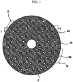
- FIG. 1 is a schematic top plan view illustrating a dispersion plate of a fluidized bed reactor in accordance with exemplary embodiments.
- FIG. 2 is a schematic cross-sectional view illustrating a construction of injection columns of a dispersion plate in accordance with exemplary embodiments.
- FIG. 2 is a cross-sectional view taken along line I-I' of FIG. 1 .
- a dispersion plate may include a base plate 50 and a plurality of injection columns 60 and 70 protruding from the base plate 50.
- the base plate 50 may be, e.g., a circular or polygonal plate formed of a metal or ceramic material.
- the injection columns 60 and 70 may have a shape protruding from a top surface of the base plate 50.
- the injection columns 60 and 70 may be regularly arranged with a constant arrangement (e.g., a constant grid arrangement) and an arrangement pitch on the top surface of the base plate 50 for a uniform diffusion and distribution of a reactive gas.
- the injection columns 60 and 70 may have an array shape or a grid shape disposed at vertices of a polygon such as a triangle, a square or a hexagon. As illustrated in FIG. 1 , the injection columns 60 and 70 may be arranged, e.g., based on an equilateral triangle pitch.
- the injection columns 60 and 70 may include first injection columns 60 disposed within a predetermined radius from a central portion C of the base plate 50 and second injection columns 70 disposed at a peripheral or outer portion of the base plate 50.
- each injection column 60 and 70 may include a column body 62 and 72 and a cap portion 64 and 74.
- the injection columns 60 and 70 may have a bubble cap or a tuyere structure.
- the first injection column 60 may include a first column body 62 and a first cap portion 64 covering an upper portion of the first column body 62.
- the second injection column 70 may include a second column body 72 and a second cap portion 74 covering an upper portion of the second column body 72.
- the first injection column 60 may include a first injection hole 66 passing through the first column body 62.
- the second injection column 70 may include a second injection hole 76 passing through the second column body 72.
- the first injection hole 66 and the second injection hole 76 may be formed to be inclined toward the base plate 50 from a top of the injection columns 60 and 70.
- the injection holes 66 and 76 may have a shape extending from the top of the injection columns 60 and 70 toward the base plate 50 .
- an inclination angle between a vertical direction from the top surface of the base plate 50 and the injection holes 66 and 76 may be from about 30 to 60°.
- the injection holes 66 and 76 are formed to be inclined with respect to the top surface of the base plate 50, so that the reactive gas may be sprayed to diffuse in a direction to the base plate 50. Accordingly, as reactants (e.g., precursor particles or active material particles) that may be settled to the top surface of the base plate 50 may move upwardly, a formation of the fluidized bed may be promoted.
- reactants e.g., precursor particles or active material particles
- a height of the second injection column 70 disposed on the peripheral portion of the base plate 50 may be greater than a height of the first injection column 60. Accordingly, a height of the second injection hole 76 may also be greater than a height of the first injection hole 66.
- a predetermined pitch e.g., a triangular arrangement
- an area where the injection columns may not be arranged by the predetermined pitch may be generated on the peripheral or outer portion of the base plate 50. Accordingly, as indicated by a dotted ellipse in FIG. 1 , a dead zone D in which the reactive gas may not reach may be generated.
- the reactive gas may not reach a wall surface of a reactor body, and a fluidized bed may not be uniformly created. Additionally, aggregated reactant particles may adhere to the wall surface of the reactor body, thereby reducing a reaction yield.
- the second injection columns having a relatively increased height may be disposed on the peripheral portion of the base plate 50 where the dead zone D may be easily generated.
- an injection distance and an injection height of the reactive gas may be increased in the peripheral portion.
- the reactive gas may reach the wall surface of the reactor body to prevent stagnation and agglomeration of the reactant particles, thereby promoting the formation of the fluidized bed.
- the dead zone D may be substantially reduced or removed at the periphery portion indicated in FIG. 1 .
- a supporter or the injection column of the dispersion plate may be disposed in a central portion C of the dispersion plate shown of FIG. 1 .
- the first injection columns 60 may also be arranged in the central portion C, and the first injection columns 60 may be arranged to a predetermined distance in a radial direction from the central portion C as described above.
- FIG. 3 is a schematic cross-sectional view for describing a construction of a second injection column in accordance with exemplary embodiments.
- a height H of the second injection hole 76 may be adjusted so that the reactive gas may contact the wall surface of the reactor body 110.
- a minimum height of the second injection hole 76 may be a height at which a straight line extending from the second injection hole 76 can reach the lowest point of the reactor body 110.
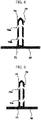
- FIGS. 4 and 5 are schematic cross-sectional views illustrating a construction of a second injection column of a dispersion plate in accordance with some exemplary embodiments.
- the second injection column 70 may include a plurality of injection holes located at different heights.
- the second injection column 50 may include an upper injection hole 76a and a lower injection hole 76b.
- a height of the upper injection hole 76a may be set such that a straight line in an injection direction may contact the wall surface of the reactor body, as described with reference to FIG. 3 .
- the height of the upper injection hole 76a may be greater than a height of the first injection hole 66 of the first injection column 60.
- the lower injection hole 76b may be added to the second injection column 70, so that the reactive gas may be additionally provided into the dead zone D indicated in FIG. 1 . Accordingly, effects of preventing particle stagnant/aggregation on the wall surface of the reactor body 110 through the upper injection hole 76a and reducing/removing the dead zone D through the lower injection hole 76b may be implemented together.
- a lower injection hole 76c may be inclined upwardly.
- the lower injection hole 76c may extend from the base plate 50 toward a top portion of the reactor body 110. In this case, a rising action of the fluidized bed may be promoted through the lower injection hole 76c.
- FIG. 6 is a schematic diagram for describing a fluidized bed reactor and a method of recovering an active metal of a lithium secondary battery utilizing the same in accordance with exemplary embodiments.
- a waste cathode active material mixture may be prepared from a waste cathode of a lithium secondary battery (e.g., in a process of S10).
- the lithium secondary battery may include an electrode assembly including a cathode, an anode, and a separation layer interposed between the cathode and the anode.
- the cathode and the anode may include a cathode active material layer and an anode active material layer coated on a cathode current collector and an anode current collector, respectively.
- the cathode active material included in the cathode active material layer may include an oxide containing lithium and a transition metal.
- the cathode active material may include a compound represented by Chemical Formula 1 below. [Chemical Formula 1] Li x M1 a M2 b M3 c O y
- M1, M2 and M3 may each be a transition metal selected from Ni, Co, Mn, Na, Mg, Ca, Ti, V, Cr, Cu, Zn, Ge, Sr, Ag, Ba, Zr, Nb, Mo, Al, Ga or B.
- the cathode active material may be an NCM-based lithium oxide including nickel, cobalt and manganese.
- the waste cathode may be recovered by separating the cathode from the waste lithium secondary battery.
- the waste cathode may include the cathode current collector (e.g., aluminum (Al)) and the cathode active material layer as described above, and the cathode active material layer may include a conductive material and a binder together with the cathode active material as described above.
- the conductive material may include, e.g., a carbon-based material such as graphite, carbon black, graphene and carbon nanotube.
- the binder may include a resin material, e.g., vinylidenefluoride-hexafluoropropylene copolymer (PVDF-co-HFP), polyvinylidenefluoride (PVDF), polyacrylonitrile, polymethylmethacrylate, etc.
- the recovered waste cathode may be pulverized to produce a waste cathode active material mixture.
- the waste cathode active material mixture may be prepared in a powder form.
- the waste cathode active material mixture may include a powder of the lithium-transition metal oxide, e.g., a powder of the NCM-based lithium oxide (e.g., Li(NCM)O 2 ).
- waste cathode active material mixture used in the present application may refer to a raw material that is input to a fluidized bed reaction treatment to be described later after the cathode current collector is substantially removed from the waste cathode.
- the waste cathode active material mixture may include cathode active material particles such as the NCM-based lithium oxide.
- the waste cathode active material mixture may include portions of components derived from the binder or the conductive material.
- the waste cathode active material mixture may substantially consist of the cathode active material particles.
- an average particle diameter (D50) of the waste cathode active material mixture may be from 5 to 100 ⁇ m.
- a lithium-transition metal oxide such as Li(NCM)O 2 to be recovered may be easily separated from the cathode current collector, the conductive material and the binder included in the waste cathode active material mixture.
- the waste cathode active material mixture may be heattreated before being input into a fluidized bed reactor to be described later. Impurities such as the conductive material and the binder included in the waste cathode active material mixture may be substantially removed or reduced by the heat treatment, so that the lithium-transition metal oxide may be introduced into the fluidized bed reactor with high purity
- a temperature of the heat treatment temperature may be, e.g., from about 100 to 500 °C, preferably from about 350 to 450 °C. Within the above range, the impurities may be substantially removed while preventing decomposition and damages of the lithium-transition metal oxide.
- the waste cathode active material mixture may be reacted in a fluidized bed reactor 100 to form a preliminary precursor mixture 90.
- the fluidized bed reactor 100 may be divided into a reactor body 110, a lower reactor portion 120 and an upper reactor portion 130.
- the reactor body 110 may include or may be integrated with a heating tool such as a heater.
- the dispersion plate described above may be coupled to a bottom portion of the reactor body 110. Accordingly, a lower portion under the dispersion plate in the reactor body 110 may be defined as the lower reactor portion 120.
- the waste cathode active material mixture may be supplied into the reactor body 110 through supply flow paths 106a and 106b.
- the waste cathode active material mixture may be dropped through a first supply flow path 106a connected to the upper reactor portion 130, or may be introduced through a second supply flow path 106b connected to the lower reactor portion 110.
- the first and second supply flow paths 106a and 106b may be used together to supply the waste cathode active material mixture.
- a reactive gas for converting the waste cathode active material mixture into a preliminary precursor may be supplied into the reactor body 110 through a reactive gas flow path 102 connected to the lower reactor portion 120.
- the reactive gas may include a reductive gas.
- hydrogen (H 2 ) may be supplied.
- the reactive gas may be discharged into the reactor body 110 through the injection columns 60 and 70 included in the dispersion plate.
- the reactive gas may be supplied from the bottom portion of the fluidized bed reactor 100 to be in contact with the waste cathode active material mixture, so that the waste cathode active material mixture may react with the reactive gas while moving to the upper reactor portion 130 to be converted into the preliminary precursor.
- the lithium-transition metal oxide may be reduced by the hydrogen gas to generate a preliminary lithium precursor including, e.g., lithium hydroxide (LiOH), lithium oxide (e.g., LiO 2 ), and a transition metal or a transition metal oxide.
- a preliminary lithium precursor including, e.g., lithium hydroxide (LiOH), lithium oxide (e.g., LiO 2 ), and a transition metal or a transition metal oxide.
- LiOH lithium hydroxide
- LiO 2 lithium oxide
- a transition metal or a transition metal oxide e.g., Ni, Co, NiO, CoO and MnO may be produced together with the preliminary lithium precursor by the reductive reaction.
- the reductive reaction in the reactor body 110 may be performed at a temperature from about 400 to 700 °C, preferably from 450 to 550 °C. Within the reaction temperature range, the reductive reaction may be promoted without causing reaggregation and recombination of the preliminary lithium precursor and the transition metal/transition metal oxide.
- a carrier gas may be supplied together with the reactive gas from the lower reactor portion 120 through a carrier gas flow path 104.
- the carrier gas may include an inert gas such as nitrogen (N2) or argon (Ar).
- the carrier gas may also be discharged and supplied through the dispersion columns 60 and 70 of the dispersion plate to promote the fluidized bed formation. For example, a cyclone formation through the carrier gas may be promoted.
- a preliminary precursor mixture 90 including preliminary lithium precursor particles 94 and transition metal-containing particles 92 (e.g., the transition metal or the transition metal oxide) may be formed in the reactor body 130.
- the preliminary lithium precursor particles 94 may include, e.g., lithium hydroxide, lithium oxide and/or lithium carbonate.
- the transition metal-containing particles 92 including nickel, cobalt or manganese may be relatively heavier than the preliminary lithium precursor particles 94, so that the preliminary lithium precursor particles 94 may be collected through outlets 160a and 160b in advance.
- the preliminary lithium precursor particles 94 may be discharged through a first outlet 160a connected to the upper reactor portion 130. In this case, a selective recovery of the preliminary lithium precursor particles 94 according to a weight gradient may be promoted.
- the preliminary precursor mixture 90 including the preliminary lithium precursor particles 94 and the transition metal-containing particles 92 may be collected through a second outlet 160b connected to the reactor body 130.
- the preliminary precursor mixture 90 may be directly recovered from a fluidized bed forming region to increase a production yield.
- the preliminary precursor mixture 90 may be collected together through the first and second outlets 160a and 160b.
- the supply of the reactive gas to the preliminary precursor mixture 90 aggerated or stagnated on the wall surface of the reactor body 110 may be facilitated through the second injection column 70 disposed on the peripheral portion of the dispersion plate 50, so that the formation of the fluidized bed may be uniformly expanded.
- an overall reaction area in the reactor body 110 may be increased to improve a reaction yield.
- the preliminary lithium precursor particles 94 collected through the outlets 160a and 160b may be recovered as a lithium precursor (e.g., in a process of S30).
- the preliminary lithium precursor particles 94 may be washed with water.
- the preliminary lithium precursor particles in the form of lithium hydroxide (LiOH) may be substantially dissolved in water by the washing treatment, separated from the transition metal precursor, and recovered in advance.
- the lithium precursor substantially consisting of lithium hydroxide may be obtained through a crystallization process, etc., of lithium hydroxide dissolved in water.
- the preliminary lithium precursor particles in the form of lithium oxide and lithium carbonate may be substantially removed through the washing treatment. In an embodiment, the preliminary lithium precursor particles in the form of lithium oxide and lithium carbonate may be at least partially converted into lithium hydroxide through the washing treatment.
- the preliminary lithium precursor particles 94 may be reacted with a carbon-containing gas such as carbon monoxide (CO), carbon dioxide (CO 2 ), etc., to obtain lithium carbonate (e.g., Li 2 CO 3 ) as the lithium precursor.
- a carbon-containing gas such as carbon monoxide (CO), carbon dioxide (CO 2 ), etc.
- lithium carbonate e.g., Li 2 CO 3
- a crystallized lithium precursor may be obtained through the reaction with the carbon-containing gas.
- lithium carbonate may be collected by injecting the carbon-containing gas together during the washing treatment.
- a transition metal precursor may be obtained from the collected transition metal-containing particles 92 (e.g., in a process of S40).
- the preliminary lithium precursor particles 94 may be collected through the outlets 160a and 160b, and then the transition metal-containing particles 92 may be recovered. Thereafter, the transition metal-containing particles 92 may be treated with an acid solution to form precursors in the form of acid salts of each transition metal.
- sulfuric acid may be used as the acid solution.
- NiSO 4 , MnSO 4 and CoSO 4 may each be recovered as the transition metal precursor.
- the lithium precursor may be collected through a dry process, and then the transition metal precursors may be selectively extracted using the acid solution, so that purity and selectivity of each metal precursor may be improved, and a load of the wet process may be reduced, and amount of wastewater and by-products may also be reduced.
Landscapes
- Chemical & Material Sciences (AREA)
- Organic Chemistry (AREA)
- Engineering & Computer Science (AREA)
- Chemical Kinetics & Catalysis (AREA)
- Materials Engineering (AREA)
- Inorganic Chemistry (AREA)
- Combustion & Propulsion (AREA)
- Electrochemistry (AREA)
- General Chemical & Material Sciences (AREA)
- Manufacturing & Machinery (AREA)
- Secondary Cells (AREA)
- Manufacture And Refinement Of Metals (AREA)
- Battery Electrode And Active Subsutance (AREA)
Abstract
Description
- The present invention relates to a fluidized bed reactor and a method of recovering an active metal of a lithium secondary battery using the same. More particularly, the present invention relates to a fluidized bed reactor including a dispersion plate and a method for recovering an active metal of a lithium secondary battery using the same.
- Recently, a secondary battery has been widely employed as a power source of a mobile electronic device such as a camcorder, a mobile phone, a laptop computer, etc., and a vehicle such as an electric vehicle, a hybrid vehicle, etc. A lithium secondary battery is highlighted among the secondary battery due to advantages such as high operational voltage and energy density per unit weight, a high charging rate, a compact dimension, etc.
- A lithium metal oxide may be used as an active material for a cathode of the lithium secondary battery. The lithium metal oxide may further contain a transition metal such as nickel, cobalt, manganese, etc.
- As the above-mentioned high-cost valuable metals are used for the cathode active material, 20% or more of a production manufacturing cost is required for manufacturing the cathode material. Additionally, as environment protection issues have recently been highlighted, a recycling method of the cathode active material is being researched.
- Conventionally, a method of sequentially recovering the valuable metals by leaching a waste cathode active material in a strong acid such as sulfuric acid has been used, but the wet process may be disadvantageous in aspect of a regeneration selectivity and a regeneration time, and may cause environmental pollution. Therefore, a method for recovering the valuable metals using a dry-based reaction through a contact with a reactive gas is being researched.
- However, as a size of the active material particles supplied for a dry reaction becomes decreased, a non-uniform reaction may occur due to an aggregation. Further, a recovery ratio of the active material may be reduced due to a local non-uniform supply of a reactive gas in a reactor.
- For example,
Korean Registered Patent Publication No. 10-0709268 - According to an aspect of the present invention, there is provided a fluidized bed reactor having improved reaction efficiency and reliability.
- According to an aspect of the present invention, there is provided a method of recovering an active metal of a lithium secondary battery using the fluidized bed reactor.
- A fluidized bed reactor according to embodiments of the present invention includes a reactor body, and a dispersion plate coupled to a bottom portion of the reactor body, the dispersion plate including a base plate and injection columns protruding from a top surface of the base plate. The injection columns include first injection columns arranged at a central portion of the dispersion plate, and second injection columns arranged at a peripheral portion of the dispersion plate, the second injection columns having a greater height than a height of the first injection columns.
- In some embodiments, the first injection column may include a first column body extending from the top surface of the base plate, a first cap portion covering an upper portion of the first column body, and a first injection hole penetrating through the first column body. The second injection column may include a second column body extending from the top surface of the base plate, a second cap portion covering an upper portion of the second column body, and a second injection hole penetrating through the second column body.
- In some embodiments, the first injection hole and the second injection hole may be inclined toward the top surface of the base plate.
- In some embodiments, a height of the second injection hole may be greater than a height of the first injection hole.
- In some embodiments, the height of the second injection hole may be adjusted so that a straight line in an inclined direction of the second injection hole may contact a wall surface of the reactor body.
- In some embodiments, the second injection hole may include an upper injection hole and a lower injection hole, and a height of the upper injection hole may be greater than a height of the first injection hole.
- In some embodiments, the upper injection hole and the lower injection hole may be inclined toward the base plate.
- In some embodiments, the upper injection hole may be inclined toward the base plate, and the lower injection hole may be inclined from the base plate toward a top portion of the reactor body.
- In some embodiments, the injection columns may be arranged in a constant pitch or in a constant grid shape.
- In some embodiments, the fluidized bed reactor may further include a reactive gas flow path for supplying a reactive gas from a portion of the reactor body under the base plate.
- In a method of recovering an active metal of a lithium secondary battery according to embodiments of the present invention, a waste cathode active material mixture obtained from a waste cathode of a lithium secondary battery is prepared. The waste cathode active material mixture is reacted in the fluidized bed reactor of embodiments as described above to form a preliminary precursor mixture. A lithium precursor is selectively recovered from the preliminary precursor mixture.
- In some embodiments, in the forming of the preliminary precursor mixture, a reactive gas may be ejected through the injection columns included in the dispersion plate of the fluidized bed reactor.
- In some embodiments, the reactive gas may include hydrogen.
- In some embodiments, the preliminary precursor mixture may include preliminary lithium precursor particles and transition metal-containing particles.
- In some embodiments, the preliminary lithium precursor particles may include at least one of lithium hydroxide, lithium oxide and lithium carbonate.
- In some embodiments, in the recovering of the lithium precursor, the preliminary lithium precursor particles may be washed with water.
- According to the above-described exemplary embodiments, a dispersion plate may be disposed at a bottom portion of a fluidized bed reactor to promote diffusion and uniform dispersion of a reactive gas. The dispersion plate may include injection columns protruding from a base plate and including an injection flow path, and a higher injection column may be disposed at a peripheral portion of the base plate.
- Accordingly, generation of a dead zone in which the reactive gas may not reach may be prevented on an inner wall of the reactor and a surface of the base plate, and uniform reaction zone and fluidized bed may be formed.
- The fluidized bed reactor according to exemplary embodiments may be utilized in a recycling process by a hydrogen reduction of a cathode active material of a lithium secondary battery. Aggregation of active material particles may be suppressed by the dispersion plate, and an active material recovery efficiency may be increased by the formation of a uniform reaction fluidized bed.
-
-
FIG. 1 is a schematic top plan view illustrating a dispersion plate of a fluidized bed reactor in accordance with exemplary embodiments. -
FIG. 2 is a schematic cross-sectional view illustrating a construction of injection columns of a dispersion plate in accordance with exemplary embodiments. -
FIG. 3 is a schematic cross-sectional view for describing a construction of a second injection column in accordance with exemplary embodiments. -
FIGS. 4 and 5 are schematic cross-sectional views illustrating a construction of a second injection column of a dispersion plate in accordance with some exemplary embodiments. -
FIG. 6 is a schematic diagram for describing a fluidized bed reactor and a method of recovering an active metal of a lithium secondary battery utilizing the same in accordance with exemplary embodiments. - Embodiments of the present invention provide a fluidized bed reactor capable of forming an entirely uniform reaction area and a fluidized bed by using a dispersion plate. Further, embodiments of the present invention provide a dry-based, high-purity, highyield method of recovering an active metal from a lithium secondary battery using the fluidized bed reactor.
- Hereinafter, embodiments of the present invention will be described in detail with reference to the accompanying drawings. However, the embodiments are provided as examples and the present invention is not limited to the specific embodiments described herein.
- As used herein, the term "precursor" is used to comprehensively refer to a compound including a specific metal to provide the specific metal included in an electrode active material.
-
FIG. 1 is a schematic top plan view illustrating a dispersion plate of a fluidized bed reactor in accordance with exemplary embodiments.FIG. 2 is a schematic cross-sectional view illustrating a construction of injection columns of a dispersion plate in accordance with exemplary embodiments. For example,FIG. 2 is a cross-sectional view taken along line I-I' ofFIG. 1 . - Referring to
FIGS. 1 and2 , a dispersion plate may include abase plate 50 and a plurality ofinjection columns base plate 50. - The
base plate 50 may be, e.g., a circular or polygonal plate formed of a metal or ceramic material. - The
injection columns base plate 50. Theinjection columns base plate 50 for a uniform diffusion and distribution of a reactive gas. - For example, the
injection columns FIG. 1 , theinjection columns - The
injection columns first injection columns 60 disposed within a predetermined radius from a central portion C of thebase plate 50 andsecond injection columns 70 disposed at a peripheral or outer portion of thebase plate 50. - As illustrated in
FIG. 2 , eachinjection column column body cap portion injection columns - The
first injection column 60 may include afirst column body 62 and afirst cap portion 64 covering an upper portion of thefirst column body 62. Thesecond injection column 70 may include asecond column body 72 and asecond cap portion 74 covering an upper portion of thesecond column body 72. - The
first injection column 60 may include afirst injection hole 66 passing through thefirst column body 62. Thesecond injection column 70 may include asecond injection hole 76 passing through thesecond column body 72. - As illustrated in
FIG. 2 , thefirst injection hole 66 and thesecond injection hole 76 may be formed to be inclined toward thebase plate 50 from a top of theinjection columns injection columns base plate 50 . - In an embodiment, an inclination angle between a vertical direction from the top surface of the
base plate 50 and the injection holes 66 and 76 may be from about 30 to 60°. - The injection holes 66 and 76 are formed to be inclined with respect to the top surface of the
base plate 50, so that the reactive gas may be sprayed to diffuse in a direction to thebase plate 50. Accordingly, as reactants (e.g., precursor particles or active material particles) that may be settled to the top surface of thebase plate 50 may move upwardly, a formation of the fluidized bed may be promoted. - In exemplary embodiments, a height of the
second injection column 70 disposed on the peripheral portion of thebase plate 50 may be greater than a height of thefirst injection column 60. Accordingly, a height of thesecond injection hole 76 may also be greater than a height of thefirst injection hole 66. - As described above, if the
injection columns base plate 50, an area where the injection columns may not be arranged by the predetermined pitch may be generated on the peripheral or outer portion of thebase plate 50. Accordingly, as indicated by a dotted ellipse inFIG. 1 , a dead zone D in which the reactive gas may not reach may be generated. - In this case, the reactive gas may not reach a wall surface of a reactor body, and a fluidized bed may not be uniformly created. Additionally, aggregated reactant particles may adhere to the wall surface of the reactor body, thereby reducing a reaction yield.
- However, according to exemplary embodiments, the second injection columns having a relatively increased height may be disposed on the peripheral portion of the
base plate 50 where the dead zone D may be easily generated. Thus, an injection distance and an injection height of the reactive gas may be increased in the peripheral portion. - Accordingly, the reactive gas may reach the wall surface of the reactor body to prevent stagnation and agglomeration of the reactant particles, thereby promoting the formation of the fluidized bed. Further, the dead zone D may be substantially reduced or removed at the periphery portion indicated in
FIG. 1 . - In a central portion C of the dispersion plate shown of
FIG. 1 , a supporter or the injection column of the dispersion plate may be disposed. For example, thefirst injection columns 60 may also be arranged in the central portion C, and thefirst injection columns 60 may be arranged to a predetermined distance in a radial direction from the central portion C as described above. -
FIG. 3 is a schematic cross-sectional view for describing a construction of a second injection column in accordance with exemplary embodiments. - Referring to
FIG. 3 , in thesecond injection column 70, a height H of thesecond injection hole 76 may be adjusted so that the reactive gas may contact the wall surface of thereactor body 110. - For example, a minimum height of the
second injection hole 76 may be a height at which a straight line extending from thesecond injection hole 76 can reach the lowest point of thereactor body 110. -
FIGS. 4 and 5 are schematic cross-sectional views illustrating a construction of a second injection column of a dispersion plate in accordance with some exemplary embodiments. - Referring to
FIGS. 4 and 5 , thesecond injection column 70 may include a plurality of injection holes located at different heights. - As illustrated in
FIG. 4 , thesecond injection column 50 may include anupper injection hole 76a and alower injection hole 76b. In some embodiments, a height of theupper injection hole 76a may be set such that a straight line in an injection direction may contact the wall surface of the reactor body, as described with reference toFIG. 3 . The height of theupper injection hole 76a may be greater than a height of thefirst injection hole 66 of thefirst injection column 60. - The
lower injection hole 76b may be added to thesecond injection column 70, so that the reactive gas may be additionally provided into the dead zone D indicated inFIG. 1 . Accordingly, effects of preventing particle stagnant/aggregation on the wall surface of thereactor body 110 through theupper injection hole 76a and reducing/removing the dead zone D through thelower injection hole 76b may be implemented together. - As illustrated in
FIG. 5 , alower injection hole 76c may be inclined upwardly. For example, thelower injection hole 76c may extend from thebase plate 50 toward a top portion of thereactor body 110. In this case, a rising action of the fluidized bed may be promoted through thelower injection hole 76c. -
FIG. 6 is a schematic diagram for describing a fluidized bed reactor and a method of recovering an active metal of a lithium secondary battery utilizing the same in accordance with exemplary embodiments. - Hereinafter, a method of recovering an active metal of a lithium secondary battery and constructions/structures of a fluidized bed reactor including the above-described dispersion plate will be described together with reference to
FIG. 6 . - Referring to
FIG. 1 , a waste cathode active material mixture may be prepared from a waste cathode of a lithium secondary battery (e.g., in a process of S10). - The lithium secondary battery may include an electrode assembly including a cathode, an anode, and a separation layer interposed between the cathode and the anode. The cathode and the anode may include a cathode active material layer and an anode active material layer coated on a cathode current collector and an anode current collector, respectively.
- For example, the cathode active material included in the cathode active material layer may include an oxide containing lithium and a transition metal.
- In some embodiments, the cathode active material may include a compound represented by Chemical Formula 1 below.
[Chemical Formula 1] LixM1aM2bM3cOy
- In Chemical Formula 1, M1, M2 and M3 may each be a transition metal selected from Ni, Co, Mn, Na, Mg, Ca, Ti, V, Cr, Cu, Zn, Ge, Sr, Ag, Ba, Zr, Nb, Mo, Al, Ga or B. In Chemical Formula 1, 0<x≤1.1, 2≤y≤2.02, 0<a<1, 0<b<1, 0<c<1, and 0<a+b+c≤1.
- In some embodiments, the cathode active material may be an NCM-based lithium oxide including nickel, cobalt and manganese.
- The waste cathode may be recovered by separating the cathode from the waste lithium secondary battery. The waste cathode may include the cathode current collector (e.g., aluminum (Al)) and the cathode active material layer as described above, and the cathode active material layer may include a conductive material and a binder together with the cathode active material as described above.
- The conductive material may include, e.g., a carbon-based material such as graphite, carbon black, graphene and carbon nanotube. The binder may include a resin material, e.g., vinylidenefluoride-hexafluoropropylene copolymer (PVDF-co-HFP), polyvinylidenefluoride (PVDF), polyacrylonitrile, polymethylmethacrylate, etc.
- In exemplary embodiments, the recovered waste cathode may be pulverized to produce a waste cathode active material mixture. Accordingly, the waste cathode active material mixture may be prepared in a powder form. As described above, the waste cathode active material mixture may include a powder of the lithium-transition metal oxide, e.g., a powder of the NCM-based lithium oxide (e.g., Li(NCM)O2).
- The term "waste cathode active material mixture" used in the present application may refer to a raw material that is input to a fluidized bed reaction treatment to be described later after the cathode current collector is substantially removed from the waste cathode. In an embodiment, the waste cathode active material mixture may include cathode active material particles such as the NCM-based lithium oxide. In an embodiment, the waste cathode active material mixture may include portions of components derived from the binder or the conductive material. In an embodiment, the waste cathode active material mixture may substantially consist of the cathode active material particles.
- In some embodiments, an average particle diameter (D50) of the waste cathode active material mixture may be from 5 to 100µm. Within the above range, a lithium-transition metal oxide such as Li(NCM)O2 to be recovered may be easily separated from the cathode current collector, the conductive material and the binder included in the waste cathode active material mixture.
- In some embodiments, the waste cathode active material mixture may be heattreated before being input into a fluidized bed reactor to be described later. Impurities such as the conductive material and the binder included in the waste cathode active material mixture may be substantially removed or reduced by the heat treatment, so that the lithium-transition metal oxide may be introduced into the fluidized bed reactor with high purity
- A temperature of the heat treatment temperature may be, e.g., from about 100 to 500 °C, preferably from about 350 to 450 °C. Within the above range, the impurities may be substantially removed while preventing decomposition and damages of the lithium-transition metal oxide.
- For example, in a process of S20, the waste cathode active material mixture may be reacted in a
fluidized bed reactor 100 to form apreliminary precursor mixture 90. - As illustrated in
FIG. 1 , thefluidized bed reactor 100 may be divided into areactor body 110, alower reactor portion 120 and anupper reactor portion 130. Thereactor body 110 may include or may be integrated with a heating tool such as a heater. - The dispersion plate described above may be coupled to a bottom portion of the
reactor body 110. Accordingly, a lower portion under the dispersion plate in thereactor body 110 may be defined as thelower reactor portion 120. - The waste cathode active material mixture may be supplied into the
reactor body 110 throughsupply flow paths 106a and 106b. The waste cathode active material mixture may be dropped through a first supply flow path 106a connected to theupper reactor portion 130, or may be introduced through a secondsupply flow path 106b connected to thelower reactor portion 110. In an embodiment, the first and secondsupply flow paths 106a and 106b may be used together to supply the waste cathode active material mixture. - A reactive gas for converting the waste cathode active material mixture into a preliminary precursor may be supplied into the
reactor body 110 through a reactivegas flow path 102 connected to thelower reactor portion 120. In some embodiments, the reactive gas may include a reductive gas. For example, hydrogen (H2) may be supplied. - The reactive gas may be discharged into the
reactor body 110 through theinjection columns fluidized bed reactor 100 to be in contact with the waste cathode active material mixture, so that the waste cathode active material mixture may react with the reactive gas while moving to theupper reactor portion 130 to be converted into the preliminary precursor. - In some embodiments, the lithium-transition metal oxide may be reduced by the hydrogen gas to generate a preliminary lithium precursor including, e.g., lithium hydroxide (LiOH), lithium oxide (e.g., LiO2), and a transition metal or a transition metal oxide. For example, Ni, Co, NiO, CoO and MnO may be produced together with the preliminary lithium precursor by the reductive reaction.
- The reductive reaction in the
reactor body 110 may be performed at a temperature from about 400 to 700 °C, preferably from 450 to 550 °C. Within the reaction temperature range, the reductive reaction may be promoted without causing reaggregation and recombination of the preliminary lithium precursor and the transition metal/transition metal oxide. - In some embodiments, a carrier gas may be supplied together with the reactive gas from the
lower reactor portion 120 through a carriergas flow path 104. For example, the carrier gas may include an inert gas such as nitrogen (N2) or argon (Ar). The carrier gas may also be discharged and supplied through thedispersion columns - A
preliminary precursor mixture 90 including preliminarylithium precursor particles 94 and transition metal-containing particles 92 (e.g., the transition metal or the transition metal oxide) may be formed in thereactor body 130. The preliminarylithium precursor particles 94 may include, e.g., lithium hydroxide, lithium oxide and/or lithium carbonate. - In an embodiment, the transition metal-containing
particles 92 including nickel, cobalt or manganese may be relatively heavier than the preliminarylithium precursor particles 94, so that the preliminarylithium precursor particles 94 may be collected throughoutlets 160a and 160b in advance. - In an embodiment, the preliminary
lithium precursor particles 94 may be discharged through a first outlet 160a connected to theupper reactor portion 130. In this case, a selective recovery of the preliminarylithium precursor particles 94 according to a weight gradient may be promoted. - In an embodiment, the
preliminary precursor mixture 90 including the preliminarylithium precursor particles 94 and the transition metal-containingparticles 92 may be collected through asecond outlet 160b connected to thereactor body 130. In this case, thepreliminary precursor mixture 90 may be directly recovered from a fluidized bed forming region to increase a production yield. - In an embodiment, the
preliminary precursor mixture 90 may be collected together through the first andsecond outlets 160a and 160b. - According to the above-described exemplary embodiments, the supply of the reactive gas to the
preliminary precursor mixture 90 aggerated or stagnated on the wall surface of thereactor body 110 may be facilitated through thesecond injection column 70 disposed on the peripheral portion of thedispersion plate 50, so that the formation of the fluidized bed may be uniformly expanded. - Thus, an overall reaction area in the
reactor body 110 may be increased to improve a reaction yield. - The preliminary
lithium precursor particles 94 collected through theoutlets 160a and 160b may be recovered as a lithium precursor (e.g., in a process of S30). - In some embodiments, the preliminary
lithium precursor particles 94 may be washed with water. The preliminary lithium precursor particles in the form of lithium hydroxide (LiOH) may be substantially dissolved in water by the washing treatment, separated from the transition metal precursor, and recovered in advance. The lithium precursor substantially consisting of lithium hydroxide may be obtained through a crystallization process, etc., of lithium hydroxide dissolved in water. - In an embodiment, the preliminary lithium precursor particles in the form of lithium oxide and lithium carbonate may be substantially removed through the washing treatment. In an embodiment, the preliminary lithium precursor particles in the form of lithium oxide and lithium carbonate may be at least partially converted into lithium hydroxide through the washing treatment.
- In some embodiments, the preliminary
lithium precursor particles 94 may be reacted with a carbon-containing gas such as carbon monoxide (CO), carbon dioxide (CO2), etc., to obtain lithium carbonate (e.g., Li2CO3) as the lithium precursor. A crystallized lithium precursor may be obtained through the reaction with the carbon-containing gas. For example, lithium carbonate may be collected by injecting the carbon-containing gas together during the washing treatment. - In some embodiments, a transition metal precursor may be obtained from the collected transition metal-containing particles 92 (e.g., in a process of S40).
- For example, the preliminary
lithium precursor particles 94 may be collected through theoutlets 160a and 160b, and then the transition metal-containingparticles 92 may be recovered. Thereafter, the transition metal-containingparticles 92 may be treated with an acid solution to form precursors in the form of acid salts of each transition metal. - In an embodiment, sulfuric acid may be used as the acid solution. In this case, NiSO4, MnSO4 and CoSO4 may each be recovered as the transition metal precursor.
- As described above, the lithium precursor may be collected through a dry process, and then the transition metal precursors may be selectively extracted using the acid solution, so that purity and selectivity of each metal precursor may be improved, and a load of the wet process may be reduced, and amount of wastewater and by-products may also be reduced.
Claims (16)
- A fluidized bed reactor, comprising:a reactor body; anda dispersion plate coupled to a bottom portion of the reactor body, the dispersion plate comprising a base plate and injection columns protruding from a top surface of the base plate;wherein the injection columns comprise:first injection columns arranged at a central portion of the dispersion plate; andsecond injection columns arranged at a peripheral portion of the dispersion plate, the second injection columns having a greater height than a height of the first injection columns.
- The fluidized bed reactor of claim 1, wherein the first injection column comprises a first column body extending from the top surface of the base plate, a first cap portion covering an upper portion of the first column body, and a first injection hole penetrating through the first column body, and
the second injection column comprises a second column body extending from the top surface of the base plate, a second cap portion covering an upper portion of the second column body, and a second injection hole penetrating through the second column body. - The fluidized bed reactor of claim 2, wherein the first injection hole and the second injection hole are inclined toward the top surface of the base plate.
- The fluidized bed reactor of claim 2, wherein a height of the second injection hole is greater than a height of the first injection hole.
- The fluidized bed reactor of claim 4, wherein the height of the second injection hole is adjusted so that a straight line in an inclined direction of the second injection hole contacts a wall surface of the reactor body.
- The fluidized bed reactor of claim 2, wherein the second injection hole comprises an upper injection hole and a lower injection hole, and a height of the upper injection hole is greater than a height of the first injection hole.
- The fluidized bed reactor of claim 6, wherein the upper injection hole and the lower injection hole are inclined toward the base plate.
- The fluidized bed reactor of claim 6, wherein the upper injection hole is inclined toward the base plate, and the lower injection hole is inclined from the base plate toward a top portion of the reactor body.
- The fluidized bed reactor of claim 1, wherein the injection columns are arranged in a constant pitch or in a constant grid shape.
- The fluidized bed reactor of claim 1, further comprising a reactive gas flow path for supplying a reactive gas from a portion of the reactor body under the base plate.
- A method of recovering an active metal of a lithium secondary battery, comprising:preparing a waste cathode active material mixture obtained from a waste cathode of a lithium secondary battery;reacting the waste cathode active material mixture in a fluidized bed reactor of claim 1 to form a preliminary precursor mixture; andselectively recovering a lithium precursor from the preliminary precursor mixture.
- The method of recovering an active metal of a lithium secondary battery of claim 11, wherein the forming the preliminary precursor mixture comprises ejecting a reactive gas through the injection columns included in the dispersion plate of the fluidized bed reactor.
- The method of recovering an active metal of a lithium secondary battery of claim 12, wherein the reactive gas comprises hydrogen.
- The method of recovering an active metal of a lithium secondary battery of claim 11, wherein the preliminary precursor mixture comprises preliminary lithium precursor particles and transition metal-containing particles.
- The method of recovering an active metal of a lithium secondary battery of claim 14, wherein the preliminary lithium precursor particles comprise at least one of lithium hydroxide, lithium oxide and lithium carbonate.
- The method of recovering an active metal of a lithium secondary battery of claim 14, wherein the recovering the lithium precursor comprises washing the preliminary lithium precursor particles with water.
Applications Claiming Priority (2)
| Application Number | Priority Date | Filing Date | Title |
|---|---|---|---|
| KR1020190176051A KR102851288B1 (en) | 2019-12-27 | 2019-12-27 | Fludized bed reactor and method of recycling active metal of lithium secondary battery utilizing the same |
| PCT/KR2020/017503 WO2021132923A1 (en) | 2019-12-27 | 2020-12-03 | Fluidized bed reactor, and method for recovering active metal of lithium secondary battery utilizing same |
Publications (2)
| Publication Number | Publication Date |
|---|---|
| EP4074413A1 true EP4074413A1 (en) | 2022-10-19 |
| EP4074413A4 EP4074413A4 (en) | 2023-04-12 |
Family
ID=76574412
Family Applications (1)
| Application Number | Title | Priority Date | Filing Date |
|---|---|---|---|
| EP20907225.5A Pending EP4074413A4 (en) | 2019-12-27 | 2020-12-03 | FLUIDIZED BED REACTOR AND METHOD FOR RECOVERING ACTIVE METAL FROM SECONDARY LITHIUM BATTERY USING SUCH REACTOR |
Country Status (6)
| Country | Link |
|---|---|
| US (1) | US20220395794A1 (en) |
| EP (1) | EP4074413A4 (en) |
| JP (1) | JP7550226B2 (en) |
| KR (2) | KR102851288B1 (en) |
| CN (1) | CN114845802B (en) |
| WO (1) | WO2021132923A1 (en) |
Cited By (1)
| Publication number | Priority date | Publication date | Assignee | Title |
|---|---|---|---|---|
| EP4095100A4 (en) * | 2020-02-18 | 2023-08-30 | SK Innovation Co., Ltd. | Fluidized bed reactor and method for recovering active metal of lithium secondary battery using same |
Families Citing this family (4)
| Publication number | Priority date | Publication date | Assignee | Title |
|---|---|---|---|---|
| KR102751369B1 (en) * | 2019-12-30 | 2025-01-06 | 에스케이이노베이션 주식회사 | Fluidized bed reactor and method of recycling active metal of lithium secondary battery utilizing the same |
| KR102856716B1 (en) * | 2020-06-01 | 2025-09-05 | 에스케이이노베이션 주식회사 | Method of recycling active metal of lithium secondary battery |
| KR102800056B1 (en) * | 2021-11-18 | 2025-04-23 | 주식회사 엘지화학 | Sparger and reactor comprising the same |
| KR20240027384A (en) * | 2022-08-23 | 2024-03-04 | 에스케이이노베이션 주식회사 | Fludized bed reactor and method of recycling active metal of lithium secondary battery utilizing the same |
Family Cites Families (22)
| Publication number | Priority date | Publication date | Assignee | Title |
|---|---|---|---|---|
| BE628052A (en) * | 1962-03-15 | |||
| US3915657A (en) * | 1974-05-21 | 1975-10-28 | Hercules Inc | Stepped distributor plate fluidized bed reactor |
| GB2085748B (en) * | 1980-10-24 | 1984-06-27 | Coal Industry Patents Ltd | Fluidised bed apparatus |
| US4429471A (en) * | 1981-12-10 | 1984-02-07 | Conoco Inc. | Fluidized bed air distributor |
| US4841884A (en) * | 1988-05-26 | 1989-06-27 | A. Ahlstrom Corporation | Distributor plate for fluidized bed reactor |
| KR100725001B1 (en) * | 2003-06-30 | 2007-06-04 | 현대중공업 주식회사 | Nozzle for Fluidizing Gas Supply for Fluidized Bed Reactor |
| KR100843601B1 (en) * | 2005-12-28 | 2008-07-03 | 주식회사 엘지화학 | Fluidized bed reactor |
| KR100709268B1 (en) | 2006-05-04 | 2007-04-19 | 한국지질자원연구원 | Waste Manganese Battery and Alkaline Battery Recycling Apparatus and Method |
| CN201168597Y (en) * | 2008-03-18 | 2008-12-24 | 河南未来铝业(集团)有限公司 | Fluidized bed cribellum and double-layer fluidized bed |
| KR101134001B1 (en) * | 2008-12-31 | 2012-04-05 | 제일모직주식회사 | Tuyere-type Distributor for Fluidized Bed Reactor for Minimizing Dead Zone |
| US8561557B2 (en) * | 2009-09-30 | 2013-10-22 | Babcock & Wilcox Power Generation Group, Inc. | Primary oxidant feed to oxy-fired circulating fluidized bed (CFB) |
| JP5772136B2 (en) * | 2011-03-28 | 2015-09-02 | 株式会社Ihi | Tar removal device |
| CN103047644A (en) * | 2013-01-28 | 2013-04-17 | 重庆大学 | Double-airflow channel air cap |
| KR101651315B1 (en) * | 2013-04-17 | 2016-08-25 | 주식회사 엘지화학 | Fluidized bed reactor and preparatio of carbon nanostructures using same |
| DE102013208274A1 (en) * | 2013-05-06 | 2014-11-20 | Wacker Chemie Ag | Fluidized bed reactor and process for producing granular polysilicon |
| KR101488705B1 (en) * | 2014-06-23 | 2015-02-04 | 이보엠텍 주식회사 | Air injection nozzle for fluidezed bed combustor |
| US9333476B2 (en) * | 2014-07-16 | 2016-05-10 | Amec Foster Wheeler North America Corp. | Grid nozzle assembly, a fluidized bed reactor with a grid nozzle assembly and methods of using a grid nozzle assembly |
| JP6448816B2 (en) * | 2015-04-01 | 2019-01-09 | ハンワ ケミカル コーポレイション | Gas distributor for fluidized bed reactor system, fluidized bed reactor system including the gas distributor, and method for producing particulate polysilicon using the fluidized bed reactor system |
| JP6991241B2 (en) * | 2017-04-28 | 2022-01-12 | スミトモ エスエイチアイ エフダブリュー エナージア オサケ ユキチュア | Fluidized bed reactor with fluidized gas nozzle head and multiple fluidized gas nozzle heads |
| KR101973483B1 (en) * | 2017-11-14 | 2019-04-29 | 강원대학교산학협력단 | Manufacturing Method of High Purity Lithium Carbonate And Barium Sulfate Using The Exhausted Lithium Ion Secondary Battery |
| JP2019156737A (en) | 2018-03-09 | 2019-09-19 | 旭化成株式会社 | Fluid bed reactor and acrylic nitrile production method |
| KR102020238B1 (en) * | 2018-04-09 | 2019-09-10 | 에스케이이노베이션 주식회사 | Method of recycling active metal of lithium secondary battery |
-
2019
- 2019-12-27 KR KR1020190176051A patent/KR102851288B1/en active Active
-
2020
- 2020-12-03 CN CN202080090214.6A patent/CN114845802B/en active Active
- 2020-12-03 EP EP20907225.5A patent/EP4074413A4/en active Pending
- 2020-12-03 JP JP2022539395A patent/JP7550226B2/en active Active
- 2020-12-03 WO PCT/KR2020/017503 patent/WO2021132923A1/en not_active Ceased
-
2022
- 2022-06-27 US US17/849,974 patent/US20220395794A1/en active Pending
-
2025
- 2025-08-22 KR KR1020250117216A patent/KR20250130760A/en active Pending
Cited By (1)
| Publication number | Priority date | Publication date | Assignee | Title |
|---|---|---|---|---|
| EP4095100A4 (en) * | 2020-02-18 | 2023-08-30 | SK Innovation Co., Ltd. | Fluidized bed reactor and method for recovering active metal of lithium secondary battery using same |
Also Published As
| Publication number | Publication date |
|---|---|
| KR102851288B1 (en) | 2025-08-28 |
| KR20250130760A (en) | 2025-09-02 |
| EP4074413A4 (en) | 2023-04-12 |
| CN114845802B (en) | 2024-11-08 |
| JP7550226B2 (en) | 2024-09-12 |
| WO2021132923A1 (en) | 2021-07-01 |
| KR20210083601A (en) | 2021-07-07 |
| US20220395794A1 (en) | 2022-12-15 |
| CN114845802A (en) | 2022-08-02 |
| JP2023508998A (en) | 2023-03-06 |
Similar Documents
| Publication | Publication Date | Title |
|---|---|---|
| US20220395794A1 (en) | Fluidized bed reactor and method for recovering active metal of lithium secondary battery utilizing same | |
| US20210115532A1 (en) | Method for recovering active metals from lithium secondary battery | |
| US12476292B2 (en) | Method for recovering active metal of lithium secondary battery | |
| US20220407133A1 (en) | Fluidized bed reactor and method for recovering active metal of lithium secondary battery using same | |
| KR102753512B1 (en) | Fluidized bed reactor and method of recycling active metal of lithium secondary battery utilizing the same | |
| US20220349022A1 (en) | Fluidized bed reactor and method for recovering active metal from lithium secondary battery thereby | |
| EP4579873A1 (en) | Fluidized bed reactor and method for recovering active metal of lithium secondary battery by using same | |
| EP4578541A1 (en) | Fluidized bed reactor and method for recovering active metal of lithium secondary battery using same | |
| JP7707179B2 (en) | Method for recovering active metals from lithium secondary batteries |
Legal Events
| Date | Code | Title | Description |
|---|---|---|---|
| STAA | Information on the status of an ep patent application or granted ep patent |
Free format text: STATUS: THE INTERNATIONAL PUBLICATION HAS BEEN MADE |
|
| PUAI | Public reference made under article 153(3) epc to a published international application that has entered the european phase |
Free format text: ORIGINAL CODE: 0009012 |
|
| STAA | Information on the status of an ep patent application or granted ep patent |
Free format text: STATUS: REQUEST FOR EXAMINATION WAS MADE |
|
| 17P | Request for examination filed |
Effective date: 20220713 |
|
| AK | Designated contracting states |
Kind code of ref document: A1 Designated state(s): AL AT BE BG CH CY CZ DE DK EE ES FI FR GB GR HR HU IE IS IT LI LT LU LV MC MK MT NL NO PL PT RO RS SE SI SK SM TR |
|
| RIC1 | Information provided on ipc code assigned before grant |
Ipc: H01M 10/54 20060101ALI20221223BHEP Ipc: C01D 15/08 20060101ALI20221223BHEP Ipc: C01D 15/02 20060101ALI20221223BHEP Ipc: B01J 8/18 20060101AFI20221223BHEP |
|
| DAV | Request for validation of the european patent (deleted) | ||
| DAX | Request for extension of the european patent (deleted) | ||
| A4 | Supplementary search report drawn up and despatched |
Effective date: 20230315 |
|
| RIC1 | Information provided on ipc code assigned before grant |
Ipc: H01M 10/54 20060101ALI20230309BHEP Ipc: C01D 15/08 20060101ALI20230309BHEP Ipc: C01D 15/02 20060101ALI20230309BHEP Ipc: B01J 8/18 20060101AFI20230309BHEP |
|
| P01 | Opt-out of the competence of the unified patent court (upc) registered |
Effective date: 20230622 |