EP4074214B1 - Toothbrush with replacable brush head - Google Patents
Toothbrush with replacable brush head Download PDFInfo
- Publication number
- EP4074214B1 EP4074214B1 EP21168873.4A EP21168873A EP4074214B1 EP 4074214 B1 EP4074214 B1 EP 4074214B1 EP 21168873 A EP21168873 A EP 21168873A EP 4074214 B1 EP4074214 B1 EP 4074214B1
- Authority
- EP
- European Patent Office
- Prior art keywords
- flexible portion
- finger
- range
- handle
- recess
- Prior art date
- Legal status (The legal status is an assumption and is not a legal conclusion. Google has not performed a legal analysis and makes no representation as to the accuracy of the status listed.)
- Active
Links
Images




Classifications
-
- A—HUMAN NECESSITIES
- A46—BRUSHWARE
- A46B—BRUSHES
- A46B5/00—Brush bodies; Handles integral with brushware
- A46B5/0095—Removable or interchangeable brush heads
-
- A—HUMAN NECESSITIES
- A46—BRUSHWARE
- A46B—BRUSHES
- A46B5/00—Brush bodies; Handles integral with brushware
- A46B5/02—Brush bodies; Handles integral with brushware specially shaped for holding by the hand
- A46B5/026—Grips or handles having a nonslip section
-
- A—HUMAN NECESSITIES
- A46—BRUSHWARE
- A46B—BRUSHES
- A46B7/00—Bristle carriers arranged in the brush body
- A46B7/04—Bristle carriers arranged in the brush body interchangeably removable bristle carriers
- A46B7/044—Sliding connections for bristle carriers
-
- F—MECHANICAL ENGINEERING; LIGHTING; HEATING; WEAPONS; BLASTING
- F16—ENGINEERING ELEMENTS AND UNITS; GENERAL MEASURES FOR PRODUCING AND MAINTAINING EFFECTIVE FUNCTIONING OF MACHINES OR INSTALLATIONS; THERMAL INSULATION IN GENERAL
- F16B—DEVICES FOR FASTENING OR SECURING CONSTRUCTIONAL ELEMENTS OR MACHINE PARTS TOGETHER, e.g. NAILS, BOLTS, CIRCLIPS, CLAMPS, CLIPS OR WEDGES; JOINTS OR JOINTING
- F16B7/00—Connections of rods or tubes, e.g. of non-circular section, mutually, including resilient connections
- F16B7/22—Connections of rods or tubes, e.g. of non-circular section, mutually, including resilient connections using hooks or like elements
-
- A—HUMAN NECESSITIES
- A46—BRUSHWARE
- A46B—BRUSHES
- A46B2200/00—Brushes characterized by their functions, uses or applications
- A46B2200/10—For human or animal care
- A46B2200/1066—Toothbrush for cleaning the teeth or dentures
Definitions
- the field of the present invention concerns a toothbrush with a replaceable brush head.
- the attachment of the handle to the brush head has been achieved by means of a snap locking mechanism;
- the snap locking mechanism includes two protuberances configured to snap into an engagement position in corresponding respective two recesses; the protuberances extend in a horizontal plane substantially perpendicular to the bristles of the brush.
- the snap engagement interference of the protuberances in the respective recesses was relatively small, thus enabling only a limited resistance to accidental detachment of the brush head during the usage of the toothbrush.
- the handle includes a longitudinal finger configured to engage into a dove-tailed groove formed in the brush head to attach the brush head to the handle.
- the finger is substantially rigid and is engaged into the dove-tailed groove along its whole longitudinal extension. Accordingly, a snap locking engagement is made possible only by a deformation of the brush head.
- the quality of the toothbrush is relatively low because the material of the brush head does not have an adequate rigidity, so that breakage or detachment of the brush head during the use of the toothbrush are possible. Furthermore, the deformability of the brush head's material may lead to a poorly effective cleaning performance of the toothbrush.
- the toothbrushes with a replaceable head of the known art were not satisfactory at least because they had a complex design, they were prone to damages and/or breakage and they employed a brush head with materials of low rigidity, thus leading to a reduced quality of the toothbrush and of its cleaning performance.
- US 5 224 234 A discloses a toothbrush with replaceable disposable bristles.
- a two unit toothbrush has a base member including a handle and a receptacle for a detachable bristle assembly unit which mates with the base member by insertion into the receptacle in which it is retained by a positive retaining member, such as a mating nib and groove.
- the bristle assembly is disposable and replaceable.
- US 6 546 585 B1 discloses a toothbrush with a detachable/replaceable head, comprising a top section having a first aperture, a second aperture, a first end and a second end.
- the first end includes a notched portion.
- the first aperture extends from the top section first end along a length of the top section within the top section.
- the second aperture is located along a top surface of the top section, a bottom section having a first end and a second end.
- the first end includes a tabbed portion which engages with the notched portion of the top section first end.
- the bottom section further includes an extension having a first end and a second end and a protrusion adjacent the extension first end wherein the extension is connected to the bottom section first end.
- the protrusion selectively cooperates with the second aperture in the top section to selectively lock and unlock the top and bottom sections.
- the extension is inserted into the first aperture of the top section.
- the extension can include a first section and a second section.
- the protrusion extends from the first section.
- the top section and bottom section can further include edges which selectively engage each other.
- US 2019/0246780 A1 discloses a connector for repeatedly attaching and detaching a head to and from a handle of a manual oral care implement has an outer surface and a recess.
- the recess forms a cavity within the connector, wherein the cavity comprises a spring-loaded ball-snap element, the element comprising a ball and a spring, the spring applying a radial force onto the ball in a direction towards the outer surface of the connector.
- an object of the present invention to provide a toothbrush with a replaceable head having a simple design which is not prone to damage and/or breakage.
- a further object of the invention is to achieve a high level of hygiene/cleaning, and to avoid small details and/or sharp edges which would be difficult to clean and more vulnerable of catching toothpaste remains and dirt; especially, in regard of the handle which is the primary part that could be more exposed to build-up of toothpaste remains.
- an object of the invention is to secure function over time and reduce bacterial growth.
- a further object of the invention is to provide a toothbrush with a replaceable brush head having a satisfactory rigidity of the components in assembled state.
- a further object of the invention is to provide toothbrush with a replaceable head allowing to achieve a desired cleaning performance.
- a further object of the invention is to provide a toothbrush with a replaceable head in which the risk of accidental detachment of the brush head during use of the toothbrush is limited.
- the present invention proposes a toothbrush as defined by claim 1.
- the finger protruding from the handle of the toothbrush includes a flexible portion (or segment) and a non-flexible portion (or segment) received in use in the recess formed in the brush head. Since the flexible portion of the finger can flex in a direction transversal to the longitudinal extension of the finger away from the bristle, a sufficiently strong snap engagement can be achieved with an adequate locking interference in a simple construction. This ensure a proper reliable function of the toothbrush with a low risk of accidental detachment during use. Furthermore, the design of the handle and, in particular, of the snap locking mechanism is rather simple and include only one movable component; this allows reducing the risk of breakage and enhance reliability of the toothbrush operation. Furthermore, thanks to the arrangement according to the invention, the brush head can be realized with a desired high rigidity, thereby ensuring high quality of the brush components and a satisfactory cleaning performance.
- the recess is open on a back side of the replaceable head opposite to the bristles. This allows to achieve a sufficiently high snap locking interference by enabling a sufficient flection of the flexible portion of the finger away from the bristles during insertion of the finger into the recess in the brush head. Furthermore, the design of the brush head is simplified and the consumption of material in the disposable element is reduced.
- the surface in the recess is inclined with respect to the longitudinal direction of an angle in the range 5°-65°, preferably in the range 20°-40°, most preferably in the range 25°-35°. This allows to easily achieve the flection of the finger during the attachment of the handle to the brush head.
- an interference height of the protrusion and an element of the recess forming the inclined surface is in the range 0,5 mm - 2,5 mm when measured in a direction perpendicular to the longitudinal direction, preferably in the range 0,5 mm - 1,2 mm, most preferably in the range 0,5 mm - 0,8 mm.
- the protrusion has a height in the range 20%-70% of the thickness of the non-flexible portion measured in a direction from a back side of the brush head to a front side of the brush head carrying the bristles, or the protrusion has a height in the range 0,5 mm - 2,5 mm, preferably in the range 0,75 mm - 1,25 mm. This allows to achieve a sufficiently strong attachment of the handle to the brush head.
- the protrusion includes a snap engagement surface facing the non-flexible portion and being inclined of an angle in the range 100°-135° with respect to the longitudinal direction, preferably in the range 110°-125°, the snap engagement surface being configured to lock the finger into the recess.
- the non-flexible portion has a T-shaped cross section. This contributes to achieve a desired rigidity of the non-flexible portion of the finger, thereby ensuring a desired mutual positioning of brush head and handle.
- the non-flexible portion includes two lateral ribs on opposite sides of the finger configured to slide and engage into corresponding grooves formed in the recess during the elastic flexing of the flexible portion. This contributes to maintaining the handle in a desired position with respect to the brush head both in use and during the insertion of the finger in the brush head's recess, thereby allowing a desired flection of the flexible portion of the finger during the snap attachment.
- the length of the non-flexible portion in the longitudinal direction is in the range 50%-80% of the whole length of the finger received in the recess, preferably in the range 65%-75% of the whole length of the finger received in the recess.
- the thickness of the non-flexible portion is in the range 55%-85% of the thickness of a segment of the handle adjacent to the non-flexible portion, preferably in the range 55%-65% of the thickness of a segment of the handle adjacent to the non-flexible portion.
- the grooves are formed adjacent to a bottom surface of the recess.
- the ribs are formed on an upper side of the finger opposite to a lower side of finger forming the back surface of the toothbrush when the brush head is mounted on the handle, wherein the ribs form a planar surface together with the upper side of the finger. This allows to achieve a desired rigidity of the brush head by forming the grooves as far as possible from the back side of the brush head, while the size of the brush head in the direction of the bristles can be reduced.
- the ribs have a thickness which is in the range 20%-65% of a thickness of the non-flexible portion measured in a direction substantially parallel to the bristles when the head is mounted on the handle, preferably in the range 30%-40% of the thickness of the non-flexible portion. This achieves a desired rigidity of the components while minimizing material consumption.
- the flexible portion forms a concavity between the non-flexible portion and the protrusion on an upper side of the finger facing the brush head when the brush head is mounted on the handle, wherein the part of the flexible portion forming the concavity has a thickness in the range 40%-80% of the thickness of the non-flexible portion in a direction substantially parallel to the bristles, preferably in the range 60%-80% of the thickness of the non-flexible portion.
- the longitudinal direction of the finger is substantially parallel to a longitudinal direction of a gripping portion of the handle, preferably the longitudinal direction of the finger being inclined less than 20° with respect to a longitudinal direction of a gripping portion of the handle.
- FIG. 1 shows a toothbrush 10 according to an embodiment of the invention in assembled state.
- the toothbrush 10 includes a handle 12 forming a gripping portion 12a of the toothbrush and a replaceable brush head 11 carrying a plurality of bristles 17.
- Both the handle 12 and the brush head 11 can be manufactured in any suitable known material, such as molded plastic.
- PP could be used as material, although other plastic materials may be used.
- the replaceable head 11 is connectable to the handle 12 in a detachable manner by means of a snap locking mechanism 13, 14.
- the snap locking mechanism includes a finger 13 protruding from the handle 12 and a recess 14 formed in the brush head 11.
- the finger 13 is formed in one piece integral with the handle 12.
- the finger 13 extends along a longitudinal direction X as shown in figure 2 .
- the longitudinal direction X of the finger is substantially parallel to a longitudinal direction of the gripping portion 12a of the handle, e.g. the longitudinal direction X of the finger may be inclined less than 20° with respect to a longitudinal direction of the gripping portion 12a of the handle.
- the finger 13 includes a flexible portion 13a and a non-flexible portion 13b that are configured to be at least partly received in the recess 14 when the brush head 11 is mounted on the handle 12; in other words, both the flexible portion 13a and the non-flexible portion 13b are received in the recess in assembled state.
- both the flexible portion 13a and the non-flexible portion 13b are received in the recess in assembled state along their whole respective length in the longitudinal direction X; as well illustrated at figure 7 , only an outer part of the flexible portion 13a and of the non-flexible portion 13b opposite to the brush head 11 is not inside the recess 14 in assembled state.
- the flexible portion 13a and the non-flexible portion 13b forms subsequent adjacent segments of the finger along the longitudinal direction X.
- the flexible portion 13a and the non-flexible portion 13b are formed integral to each other, preferably of the same molded plastic material as the handle 12.
- the material used to manufacture the finger 13, such as molded plastic, is chosen to ensure a sufficient degree of flexibility of the non-flexible portion to enable the snap engagement as described later.
- the non-flexible portion 13b connects the flexible portion 13a to the handle 12.
- the flexible portion 13a is configured to elastically flex away from the bristles 17 with respect to the non-flexible portion 13b in a direction transversal to the longitudinal direction X during the insertion of the finger 13 into the recess 14 along the longitudinal direction X.
- the flexible finger portion 13a is configured to flex due to the interaction with an inclined surface 18 formed in the recess 14 during insertion of the finger 13 into the recess 14 along the longitudinal direction X (see figures 4-6 ).
- the flexible portion 13a includes a protrusion 19 configured to snap into an engagement position with the recess 14 when the protrusion 19 slides beyond the inclined surface 18 inside the recess 14 (see figure 7 ).
- the protrusion 19 engages with the element 32 forming the inclined surface 18 inside the recess 14.
- the protrusion 19 is formed at the end of the finger 13, far from the handle 12.
- an interference height i of the protrusion 19 and the inclined surface 18 is in the range 0,5 mm - 2,5 mm when measured in the direction Y perpendicular to the longitudinal direction X, preferably in the range 0,5 mm - 1,2 mm, most preferably 0,5 mm - 0,8 mm.
- the direction Y is a direction substantially perpendicular to the longitudinal direction X of the finger that leads from a back side of the brush head to a front side of the brush head carrying the bristles 17; the direction Y may also correspond to a direction substantially parallel to the bristles 17, although it is known that the bristles 17 may have different inclinations with respect to the brush head.
- the interference height i determines the strength of the snap engagement and ensures that the risk of accidental detachment of the brush head from the handle is reduced during use. In fact, the height i will affect the force needed to assemble and disassemble the head.
- the snap locking mechanism is designed to be hard to disengage while in use, i.e. while the toothbrush is used to clean the teeth.
- the majority of the forces applied to the bristles works perpendicular to the longitudinal direction X, thus creating a stronger engagement between the protrusion 19 and the element 32 forming the inclined surface 18.
- the brush head 11 can be detached from the handle 12 manually by the user, pulling the two components 11 and 12 away from each other along the longitudinal direction X.
- the angle ⁇ discussed later with reference to figure 10 and the interference i ensures that the force for detaching the brush head from the handle can be comfortably exerted by the user, while at the same time reducing the risk of accidental detachment of the head during use.
- the recess 14 is open on a back side of the replaceable head 11 opposite to the bristles 17.
- the recess 14 includes an end facing the handle during the insertion which is open in the longitudinal direction to allow the insertion of the finger along the direction X.
- the recess 14 includes an end closed in the longitudinal direction so as to form an arrest surface which the finger 13 abuts in assembled state (see figure 7 ).
- the non-flexible portion 13b has a T-shaped cross section, e.g. obtained by means of two longitudinal ribs 20.
- the flexible portion 13a does not have a T-shaped cross section.
- the flexible portion 13a may have a rectangular cross section, in order to achieve a desired degree of flexibility.
- the non-flexible portion 13b includes two lateral ribs 20 on opposite sides of the finger 13 configured to slide and engage into corresponding grooves 21 formed in the recess 14 during the elastic flexing of the flexible portion 13a.
- the ribs 20 are parallel to the longitudinal direction X of the finger 13.
- the ribs 20 extends along the whole length of the non-flexible portion 13b in the direction X.
- the ribs 20 contribute to avoid substantial deformations of the non-flexible portion 13b during the detachment and attachment to the brush head.
- the ribs 20 do not extend to the handle 12 or to flexible portion 13a.
- the ribs 20 are formed on an upper side of the finger 13 opposite to a lower side of finger forming the back surface of the toothbrush when the brush head 11 is mounted on the handle 12.
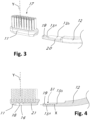
- the ribs 20 may form a planar surface together with the upper side of the finger 13 as shown e.g. at figure 3 .
- the grooves 21 are preferably formed adjacent to a bottom surface 30 of the recess 14.
- the ribs 20 have a thickness which is in the range 20%-65% of a thickness c of the non-flexible portion 13b measured in the direction Y substantially parallel to the bristles 17 when the head is mounted on the handle, preferably in the range 30%-40% of the thickness c of the non-flexible portion 13b.
- the ribs 20 have a thickness of approximately 1 mm; depending on the tufting technologies or used materials, however, the head and the ribs might be thinner.
- the grooves 21 have a thickness corresponding to the thickness of the ribs 20.
- the length a of the non-flexible portion 13b in the longitudinal direction X is in the range 50%-80% of the whole length b of the finger 13 received in the recess 14, preferably in the range 65%-75% of the whole length b of the finger 13 received in the recess 14.
- the length a is approximately 16 mm
- the length b is approximately 23 mm, although other dimensions may be adopted.
- the flexible portion 13a forms a concavity 31 (see figure 4 ) between the non-flexible portion 13b and the protrusion 19 on an upper side of the finger facing the brush head when the brush head 11 is mounted on the handle 12.
- the part of the flexible portion 13a forming the concavity 31 has a thickness in the range 40%-80% of the thickness c of the non-flexible portion 13b in a direction substantially parallel to the bristles 17, preferably in the range 60%-80% of the thickness c of the non-flexible portion 13b.
- the thickness of the flexible portion forming the concavity 31 is approximately 2,15 mm, e.g. in the range 2 mm - 2,3 mm, although other dimensions may be adopted.
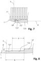
- the thickness c of the non-flexible portion 13b is in the range 55%-85% of the thickness d of a segment of the handle 12 adjacent to the non-flexible portion 13b, preferably in the range 55%-65% of the thickness d of a segment of the handle 12 adjacent to the non-flexible portion 13b (see figure 8 ).
- the thickness d is approximately 5 mm, e.g. in the range 4 mm - 6 mm, although other dimensions may be adopted.
- the surface 18 is inclined with respect to the longitudinal direction X of an angle ⁇ in the range 5°-65°, preferably in the range 20°-40°, most preferably in the range 25°-35°.
- the angle ⁇ may be approximately 30°.
- the protrusion 19 includes a snap engagement surface 19a facing the non-flexible portion 13b and being inclined of an angle ⁇ in the range 100°-135° with respect to the longitudinal direction X, preferably in the range 110°-125°. In a specific example, the angle ⁇ is approximately 115°.
- the snap engagement surface 19a is configured to lock the finger 13 into the recess 14 by cooperating with the element 32 forming the inclined surface 18.
- the protrusion 19 has a height h in the range 20%-70% of the thickness c of the non-flexible portion 13b measured in a direction Y from a back side of the brush head to a front side of the brush head carrying the bristles, or the protrusion 19 has a height h in the range 0,5 mm - 2,5 mm, preferably in the range 0,75 mm - 1,25 mm.
- the height h is approximately 1 mm and the thickness c is approximately 3 mm, although other dimensions may be adopted.
- Figure 4 shows the phase in which the handle 12 is approached to the brush head 11 before the engagement.
- the finger 13 is brought in the vicinity of the recess 14 along the longitudinal direction X.
- Figure 5 shows the finger 13 engaged in the recess 14 before the snap engagement; in this phase the ribs 20 of the non-flexible portion 13b engages in a slidable manner in the grooves 21 in the recess 14, but the flexible portion 13a has not yet undergone any flection; in this phase the finger 13 can slide along the longitudinal direction X which corresponds to the direction of insertion of the finger 13 into the recess 14.
- Figure 6 shows the phase in which the flexible portion 13a flexes away from the bristles 17 in a direction substantially perpendicular to the longitudinal direction X, as shown by the arrow; the flection is caused by the sliding engagement of the protrusion 19 with the inclined surface 18 in the recess 14, under the force applied by the user in the direction X to attach the head 11 to the handle 12.
- Figure 7 shows the head 11 locked to the handle 12, where the protrusion 19 snapped into an engagement position in the recess and locks the head 11 to the handle 12 by cooperating with the element 32 forming the inclined surface 19.
- the flexible finger portion 13a is configured to flex due to the interaction with an inclined surface 18 formed in the recess 14 during insertion of the finger 13 into the recess 14 along the longitudinal direction X (see figures 4-6 ), wherein the inclined surface 18 is formed by a local detail, i.e. element 32, protruding locally from the bottom surface of the recess 14.
- the inclined surface 118 causing the flection of the flexible portion of the finger could be formed by the base surface of the recess; in this case, the bottom surface of the recess may be ramped along substantially the whole length of the recess until the end of the element 132 forming the locking detail of the snap locking mechanism.
- the non-flexible portion of the finger may advantageously be tapered.
Landscapes
- Engineering & Computer Science (AREA)
- General Engineering & Computer Science (AREA)
- Mechanical Engineering (AREA)
- Brushes (AREA)
Description
- The field of the present invention concerns a toothbrush with a replaceable brush head.
- It is known in the art to produce toothbrushes with a replaceable brush head that can be detached from the handle to be removed and replaced by a new brush head. This allows to save the material of the handle when the brush head needs to be replaced to ensure a desired functionality of the toothbrush, thus reducing the environmental impact of the product.
- According to a known technique, the attachment of the handle to the brush head has been achieved by means of a snap locking mechanism; the snap locking mechanism includes two protuberances configured to snap into an engagement position in corresponding respective two recesses; the protuberances extend in a horizontal plane substantially perpendicular to the bristles of the brush. These known toothbrushes were not satisfactory, because they involved a complex design including a plurality of flexible components of small dimensions that could be prone to damage and/or breakage. Furthermore, they were not good for hygiene/bacterial growth. Small details tend to catch toothpaste and bacteria, and are difficult to clean. Build-up of toothpaste remains could also possibly affect locking function over time. Furthermore, due to the limited available dimension corresponding to the breadth of the brush head, the snap engagement interference of the protuberances in the respective recesses was relatively small, thus enabling only a limited resistance to accidental detachment of the brush head during the usage of the toothbrush.
- According to another known technique, the handle includes a longitudinal finger configured to engage into a dove-tailed groove formed in the brush head to attach the brush head to the handle. In this known art, the finger is substantially rigid and is engaged into the dove-tailed groove along its whole longitudinal extension. Accordingly, a snap locking engagement is made possible only by a deformation of the brush head. In this conventional technique, the quality of the toothbrush is relatively low because the material of the brush head does not have an adequate rigidity, so that breakage or detachment of the brush head during the use of the toothbrush are possible. Furthermore, the deformability of the brush head's material may lead to a poorly effective cleaning performance of the toothbrush.
- Hence, the toothbrushes with a replaceable head of the known art were not satisfactory at least because they had a complex design, they were prone to damages and/or breakage and they employed a brush head with materials of low rigidity, thus leading to a reduced quality of the toothbrush and of its cleaning performance.
-
US 5 224 234 A discloses a toothbrush with replaceable disposable bristles. A two unit toothbrush has a base member including a handle and a receptacle for a detachable bristle assembly unit which mates with the base member by insertion into the receptacle in which it is retained by a positive retaining member, such as a mating nib and groove. The bristle assembly is disposable and replaceable. -
US 6 546 585 B1 discloses a toothbrush with a detachable/replaceable head, comprising a top section having a first aperture, a second aperture, a first end and a second end. The first end includes a notched portion. The first aperture extends from the top section first end along a length of the top section within the top section. The second aperture is located along a top surface of the top section, a bottom section having a first end and a second end. The first end includes a tabbed portion which engages with the notched portion of the top section first end. The bottom section further includes an extension having a first end and a second end and a protrusion adjacent the extension first end wherein the extension is connected to the bottom section first end. The protrusion selectively cooperates with the second aperture in the top section to selectively lock and unlock the top and bottom sections. The extension is inserted into the first aperture of the top section. The extension can include a first section and a second section. The protrusion extends from the first section. The top section and bottom section can further include edges which selectively engage each other. -
US 2019/0246780 A1 discloses a connector for repeatedly attaching and detaching a head to and from a handle of a manual oral care implement has an outer surface and a recess. The recess forms a cavity within the connector, wherein the cavity comprises a spring-loaded ball-snap element, the element comprising a ball and a spring, the spring applying a radial force onto the ball in a direction towards the outer surface of the connector. - In view of the above problems, it is an object of the present invention to provide a toothbrush with a replaceable head having a simple design which is not prone to damage and/or breakage. A further object of the invention is to achieve a high level of hygiene/cleaning, and to avoid small details and/or sharp edges which would be difficult to clean and more vulnerable of catching toothpaste remains and dirt; especially, in regard of the handle which is the primary part that could be more exposed to build-up of toothpaste remains. Hence, an object of the invention is to secure function over time and reduce bacterial growth. A further object of the invention is to provide a toothbrush with a replaceable brush head having a satisfactory rigidity of the components in assembled state. A further object of the invention is to provide toothbrush with a replaceable head allowing to achieve a desired cleaning performance. A further object of the invention is to provide a toothbrush with a replaceable head in which the risk of accidental detachment of the brush head during use of the toothbrush is limited.
- In view of the above objects, the present invention proposes a toothbrush as defined by claim 1.
- According to the invention, the finger protruding from the handle of the toothbrush includes a flexible portion (or segment) and a non-flexible portion (or segment) received in use in the recess formed in the brush head. Since the flexible portion of the finger can flex in a direction transversal to the longitudinal extension of the finger away from the bristle, a sufficiently strong snap engagement can be achieved with an adequate locking interference in a simple construction. This ensure a proper reliable function of the toothbrush with a low risk of accidental detachment during use. Furthermore, the design of the handle and, in particular, of the snap locking mechanism is rather simple and include only one movable component; this allows reducing the risk of breakage and enhance reliability of the toothbrush operation. Furthermore, thanks to the arrangement according to the invention, the brush head can be realized with a desired high rigidity, thereby ensuring high quality of the brush components and a satisfactory cleaning performance.
- According to an embodiment, the recess is open on a back side of the replaceable head opposite to the bristles. This allows to achieve a sufficiently high snap locking interference by enabling a sufficient flection of the flexible portion of the finger away from the bristles during insertion of the finger into the recess in the brush head. Furthermore, the design of the brush head is simplified and the consumption of material in the disposable element is reduced.
- According to an embodiment, when the brush head is mounted on the handle, the surface in the recess is inclined with respect to the longitudinal direction of an angle in the range 5°-65°, preferably in the
range 20°-40°, most preferably in the range 25°-35°. This allows to easily achieve the flection of the finger during the attachment of the handle to the brush head. - According to an embodiment, when the protrusion is in the engagement position with the recess, an interference height of the protrusion and an element of the recess forming the inclined surface is in the range 0,5 mm - 2,5 mm when measured in a direction perpendicular to the longitudinal direction, preferably in the range 0,5 mm - 1,2 mm, most preferably in the range 0,5 mm - 0,8 mm. This allows to achieve a sufficiently strong attachment of the handle to the brush head, thereby reducing the risk of accidental detachment in use. At the same time, the force needed to detach the brush head from the handle is sufficiently low to ensure a comfortable and intuitive replacement by the user.
- According to an embodiment, the protrusion has a height in the
range 20%-70% of the thickness of the non-flexible portion measured in a direction from a back side of the brush head to a front side of the brush head carrying the bristles, or the protrusion has a height in the range 0,5 mm - 2,5 mm, preferably in the range 0,75 mm - 1,25 mm. This allows to achieve a sufficiently strong attachment of the handle to the brush head. - According to an embodiment, the protrusion includes a snap engagement surface facing the non-flexible portion and being inclined of an angle in the range 100°-135° with respect to the longitudinal direction, preferably in the range 110°-125°, the snap engagement surface being configured to lock the finger into the recess. This contributes to achieve a sufficiently strong attachment of the handle to the brush head, thereby reducing the risk of accidental detachment in use.
- According to an embodiment, the non-flexible portion has a T-shaped cross section. This contributes to achieve a desired rigidity of the non-flexible portion of the finger, thereby ensuring a desired mutual positioning of brush head and handle.
- According to an embodiment, the non-flexible portion includes two lateral ribs on opposite sides of the finger configured to slide and engage into corresponding grooves formed in the recess during the elastic flexing of the flexible portion. This contributes to maintaining the handle in a desired position with respect to the brush head both in use and during the insertion of the finger in the brush head's recess, thereby allowing a desired flection of the flexible portion of the finger during the snap attachment.
- According to an embodiment, the length of the non-flexible portion in the longitudinal direction is in the range 50%-80% of the whole length of the finger received in the recess, preferably in the range 65%-75% of the whole length of the finger received in the recess. This allows to achieve a desired mutual positioning of the handle with respect to the brush head both in use and during the insertion of the finger in the brush head's recess; furthermore, this feature ensures an opportune length of the flexible portion of the finger, thereby contributing to enable an opportune flection of the flexible portion of the finger according to an optimal snap engagement interference height.
- According to an embodiment, with respect to a direction substantially parallel to the bristles, the thickness of the non-flexible portion is in the range 55%-85% of the thickness of a segment of the handle adjacent to the non-flexible portion, preferably in the range 55%-65% of the thickness of a segment of the handle adjacent to the non-flexible portion. This allows to achieve material savings in the toothbrush due to the reduced thickness of the finger portion, while ensuring a proper rigidity of the article in the assembled state.
- According to an embodiment, the grooves are formed adjacent to a bottom surface of the recess. Further, according to an embodiment, the ribs are formed on an upper side of the finger opposite to a lower side of finger forming the back surface of the toothbrush when the brush head is mounted on the handle, wherein the ribs form a planar surface together with the upper side of the finger. This allows to achieve a desired rigidity of the brush head by forming the grooves as far as possible from the back side of the brush head, while the size of the brush head in the direction of the bristles can be reduced.
- According to an embodiment, the ribs have a thickness which is in the
range 20%-65% of a thickness of the non-flexible portion measured in a direction substantially parallel to the bristles when the head is mounted on the handle, preferably in therange 30%-40% of the thickness of the non-flexible portion. This achieves a desired rigidity of the components while minimizing material consumption. - According to an embodiment, the flexible portion forms a concavity between the non-flexible portion and the protrusion on an upper side of the finger facing the brush head when the brush head is mounted on the handle, wherein the part of the flexible portion forming the concavity has a thickness in the range 40%-80% of the thickness of the non-flexible portion in a direction substantially parallel to the bristles, preferably in the range 60%-80% of the thickness of the non-flexible portion. This allows to achieve a sufficient flexibility of the flexible portion to achieve the snap engaging movement with the desired snap engagement interference under the forces that can be comfortably exerted by a user.
- According to an embodiment, the longitudinal direction of the finger is substantially parallel to a longitudinal direction of a gripping portion of the handle, preferably the longitudinal direction of the finger being inclined less than 20° with respect to a longitudinal direction of a gripping portion of the handle.
- The above and other advantages of the present invention will be illustrated with reference to example embodiments of the invention, described with reference to the appended drawings listed as follows.
-
Fig. 1 shows a view of the toothbrush according to an embodiment of the present invention in assembled state; -
Fig. 2 shows the brush head and the handle of the toothbrush in a detached state; -
Fig. 3 shows another view of the brush head and the handle of the toothbrush in a detached state; -
Figs. 4-7 show cross sections of the brush head and the handle in different subsequent phases of the attachment process; -
Fig. 8 and10 show details of the finger of the handle in cross section; -
Fig. 9 shows details of the brush head in cross section, -
Fig. 11 shows details of a brush head of an alternative embodiment in cross section. -
Figure 1 shows atoothbrush 10 according to an embodiment of the invention in assembled state. Thetoothbrush 10 includes ahandle 12 forming a gripping portion 12a of the toothbrush and areplaceable brush head 11 carrying a plurality ofbristles 17. Both thehandle 12 and thebrush head 11 can be manufactured in any suitable known material, such as molded plastic. For example, PP could be used as material, although other plastic materials may be used. - As shown in
figures 2-7 , thereplaceable head 11 is connectable to thehandle 12 in a detachable manner by means of asnap locking mechanism finger 13 protruding from thehandle 12 and arecess 14 formed in thebrush head 11. Advantageously, thefinger 13 is formed in one piece integral with thehandle 12. Thefinger 13 extends along a longitudinal direction X as shown infigure 2 . Preferably, the longitudinal direction X of the finger is substantially parallel to a longitudinal direction of the gripping portion 12a of the handle, e.g. the longitudinal direction X of the finger may be inclined less than 20° with respect to a longitudinal direction of the gripping portion 12a of the handle. - The
finger 13 includes aflexible portion 13a and anon-flexible portion 13b that are configured to be at least partly received in therecess 14 when thebrush head 11 is mounted on thehandle 12; in other words, both theflexible portion 13a and thenon-flexible portion 13b are received in the recess in assembled state. Preferably, both theflexible portion 13a and thenon-flexible portion 13b are received in the recess in assembled state along their whole respective length in the longitudinal direction X; as well illustrated atfigure 7 , only an outer part of theflexible portion 13a and of thenon-flexible portion 13b opposite to thebrush head 11 is not inside therecess 14 in assembled state. - As shown in
figure 2 , theflexible portion 13a and thenon-flexible portion 13b forms subsequent adjacent segments of the finger along the longitudinal direction X. Theflexible portion 13a and thenon-flexible portion 13b are formed integral to each other, preferably of the same molded plastic material as thehandle 12. The material used to manufacture thefinger 13, such as molded plastic, is chosen to ensure a sufficient degree of flexibility of the non-flexible portion to enable the snap engagement as described later. Thenon-flexible portion 13b connects theflexible portion 13a to thehandle 12. - As well shown in
figure 6 , theflexible portion 13a is configured to elastically flex away from thebristles 17 with respect to thenon-flexible portion 13b in a direction transversal to the longitudinal direction X during the insertion of thefinger 13 into therecess 14 along the longitudinal direction X. - The
flexible finger portion 13a is configured to flex due to the interaction with aninclined surface 18 formed in therecess 14 during insertion of thefinger 13 into therecess 14 along the longitudinal direction X (seefigures 4-6 ). Theflexible portion 13a includes aprotrusion 19 configured to snap into an engagement position with therecess 14 when theprotrusion 19 slides beyond theinclined surface 18 inside the recess 14 (seefigure 7 ). Specifically, theprotrusion 19 engages with theelement 32 forming theinclined surface 18 inside therecess 14. Advantageously, theprotrusion 19 is formed at the end of thefinger 13, far from thehandle 12. - As shown at
figure 7 , when theprotrusion 19 is in the engagement position with therecess 14, an interference height i of theprotrusion 19 and theinclined surface 18 is in the range 0,5 mm - 2,5 mm when measured in the direction Y perpendicular to the longitudinal direction X, preferably in the range 0,5 mm - 1,2 mm, most preferably 0,5 mm - 0,8 mm. In the present disclosure, the direction Y is a direction substantially perpendicular to the longitudinal direction X of the finger that leads from a back side of the brush head to a front side of the brush head carrying thebristles 17; the direction Y may also correspond to a direction substantially parallel to thebristles 17, although it is known that thebristles 17 may have different inclinations with respect to the brush head. The interference height i determines the strength of the snap engagement and ensures that the risk of accidental detachment of the brush head from the handle is reduced during use. In fact, the height i will affect the force needed to assemble and disassemble the head. The snap locking mechanism is designed to be hard to disengage while in use, i.e. while the toothbrush is used to clean the teeth. In fact, the majority of the forces applied to the bristles (while brushing the teeth) works perpendicular to the longitudinal direction X, thus creating a stronger engagement between theprotrusion 19 and theelement 32 forming theinclined surface 18. Thebrush head 11 can be detached from thehandle 12 manually by the user, pulling the twocomponents figure 10 and the interference i ensures that the force for detaching the brush head from the handle can be comfortably exerted by the user, while at the same time reducing the risk of accidental detachment of the head during use. - Preferably, the
recess 14 is open on a back side of thereplaceable head 11 opposite to thebristles 17. Therecess 14 includes an end facing the handle during the insertion which is open in the longitudinal direction to allow the insertion of the finger along the direction X. At the opposite side, therecess 14 includes an end closed in the longitudinal direction so as to form an arrest surface which thefinger 13 abuts in assembled state (seefigure 7 ). - Preferably, the
non-flexible portion 13b has a T-shaped cross section, e.g. obtained by means of twolongitudinal ribs 20. Theflexible portion 13a does not have a T-shaped cross section. Theflexible portion 13a may have a rectangular cross section, in order to achieve a desired degree of flexibility. - In the illustrated embodiment, the
non-flexible portion 13b includes twolateral ribs 20 on opposite sides of thefinger 13 configured to slide and engage intocorresponding grooves 21 formed in therecess 14 during the elastic flexing of theflexible portion 13a. Theribs 20 are parallel to the longitudinal direction X of thefinger 13. Advantageously, theribs 20 extends along the whole length of thenon-flexible portion 13b in the direction X. Theribs 20 contribute to avoid substantial deformations of thenon-flexible portion 13b during the detachment and attachment to the brush head. Theribs 20 do not extend to thehandle 12 or toflexible portion 13a. Advantageously, theribs 20 are formed on an upper side of thefinger 13 opposite to a lower side of finger forming the back surface of the toothbrush when thebrush head 11 is mounted on thehandle 12. Theribs 20 may form a planar surface together with the upper side of thefinger 13 as shown e.g. atfigure 3 . As well illustrated atfigure 9 , thegrooves 21 are preferably formed adjacent to abottom surface 30 of therecess 14. Theribs 20 have a thickness which is in therange 20%-65% of a thickness c of thenon-flexible portion 13b measured in the direction Y substantially parallel to thebristles 17 when the head is mounted on the handle, preferably in therange 30%-40% of the thickness c of thenon-flexible portion 13b. In a specific example, theribs 20 have a thickness of approximately 1 mm; depending on the tufting technologies or used materials, however, the head and the ribs might be thinner. Thegrooves 21 have a thickness corresponding to the thickness of theribs 20. - As shown in
figure 8 , the length a of thenon-flexible portion 13b in the longitudinal direction X is in the range 50%-80% of the whole length b of thefinger 13 received in therecess 14, preferably in the range 65%-75% of the whole length b of thefinger 13 received in therecess 14. In a specific example, the length a is approximately 16 mm, and the length b is approximately 23 mm, although other dimensions may be adopted. - The
flexible portion 13a forms a concavity 31 (seefigure 4 ) between thenon-flexible portion 13b and theprotrusion 19 on an upper side of the finger facing the brush head when thebrush head 11 is mounted on thehandle 12. The part of theflexible portion 13a forming theconcavity 31 has a thickness in the range 40%-80% of the thickness c of thenon-flexible portion 13b in a direction substantially parallel to thebristles 17, preferably in the range 60%-80% of the thickness c of thenon-flexible portion 13b. In a specific example, the thickness of the flexible portion forming theconcavity 31 is approximately 2,15 mm, e.g. in the range 2 mm - 2,3 mm, although other dimensions may be adopted. - With respect to the direction Y substantially parallel to the
bristles 17 when the head is mounted on the handle, the thickness c of thenon-flexible portion 13b is in the range 55%-85% of the thickness d of a segment of thehandle 12 adjacent to thenon-flexible portion 13b, preferably in the range 55%-65% of the thickness d of a segment of thehandle 12 adjacent to thenon-flexible portion 13b (seefigure 8 ). In a specific example, the thickness d is approximately 5 mm, e.g. in the range 4 mm - 6 mm, although other dimensions may be adopted. - As shown at
figure 9 , when thebrush head 11 is mounted on the handle, thesurface 18 is inclined with respect to the longitudinal direction X of an angle β in the range 5°-65°, preferably in therange 20°-40°, most preferably in the range 25°-35°. In a specific example, the angle β may be approximately 30°. - As shown at
figure 10 , theprotrusion 19 includes asnap engagement surface 19a facing thenon-flexible portion 13b and being inclined of an angle α in the range 100°-135° with respect to the longitudinal direction X, preferably in the range 110°-125°. In a specific example, the angle α is approximately 115°. Thesnap engagement surface 19a is configured to lock thefinger 13 into therecess 14 by cooperating with theelement 32 forming theinclined surface 18. - As further shown in
figure 10 , theprotrusion 19 has a height h in therange 20%-70% of the thickness c of thenon-flexible portion 13b measured in a direction Y from a back side of the brush head to a front side of the brush head carrying the bristles, or theprotrusion 19 has a height h in the range 0,5 mm - 2,5 mm, preferably in the range 0,75 mm - 1,25 mm. In a specific example, the height h is approximately 1 mm and the thickness c is approximately 3 mm, although other dimensions may be adopted. - With reference to
figure 4-7 , the attachment of thehead 11 to thehandle 12 is further described.Figure 4 shows the phase in which thehandle 12 is approached to thebrush head 11 before the engagement. Thefinger 13 is brought in the vicinity of therecess 14 along the longitudinal direction X.Figure 5 shows thefinger 13 engaged in therecess 14 before the snap engagement; in this phase theribs 20 of thenon-flexible portion 13b engages in a slidable manner in thegrooves 21 in therecess 14, but theflexible portion 13a has not yet undergone any flection; in this phase thefinger 13 can slide along the longitudinal direction X which corresponds to the direction of insertion of thefinger 13 into therecess 14.Figure 6 shows the phase in which theflexible portion 13a flexes away from thebristles 17 in a direction substantially perpendicular to the longitudinal direction X, as shown by the arrow; the flection is caused by the sliding engagement of theprotrusion 19 with theinclined surface 18 in therecess 14, under the force applied by the user in the direction X to attach thehead 11 to thehandle 12.Figure 7 shows thehead 11 locked to thehandle 12, where theprotrusion 19 snapped into an engagement position in the recess and locks thehead 11 to thehandle 12 by cooperating with theelement 32 forming theinclined surface 19. - The above description of embodiments applying the innovative principles of the invention is provided solely for the purpose of illustrating said principles and must thus not be considered as limiting the scope of the invention claimed herein.
- According to the preferred embodiment above described, the
flexible finger portion 13a is configured to flex due to the interaction with aninclined surface 18 formed in therecess 14 during insertion of thefinger 13 into therecess 14 along the longitudinal direction X (seefigures 4-6 ), wherein theinclined surface 18 is formed by a local detail, i.e.element 32, protruding locally from the bottom surface of therecess 14. However, according to an alternative embodiment of thebrush head 111 as illustrated infigure 11 , theinclined surface 118 causing the flection of the flexible portion of the finger could be formed by the base surface of the recess; in this case, the bottom surface of the recess may be ramped along substantially the whole length of the recess until the end of theelement 132 forming the locking detail of the snap locking mechanism. In this embodiment, the non-flexible portion of the finger may advantageously be tapered.
Claims (13)
- A toothbrush (10) including a handle (12) forming a gripping portion (12a) of the toothbrush and a replaceable brush head (11) carrying a plurality of bristles (17),wherein the replaceable head (11) is connectable to the handle (12) in a detachable manner by means of a snap locking mechanism (13, 14),the snap locking mechanism including a finger (13) protruding from the handle (12) and a recess (14) formed in the brush head (11),wherein the finger (13) extends along a longitudinal direction,wherein the finger (13) includes a flexible portion (13a) and a non-flexible portion (13b) that are integral to each other and that are configured to be at least partly received in the recess (14) when the brush head (11) is mounted on the handle (12);wherein the non-flexible portion (13b) connects the flexible portion (13a) to the handle (12);wherein the flexible portion (13a) is configured to elastically flex away from the bristles (17) with respect to the non-flexible portion (13b) in a direction transversal to the longitudinal direction (X) during the insertion of the finger (13) into the recess (14) along the longitudinal direction (X),wherein the flexible portion (13a) is configured to flex due to the interaction with an inclined surface (18) formed in the recess (14) during insertion of the finger (13) into the recess (14) along the longitudinal direction (X),wherein the flexible portion (13a) includes a protrusion (19) configured to snap into an engagement position with the recess (14) when the protrusion (19) slides beyond the inclined surface (18) inside the recess (14),wherein the recess (14) is open on a back side of the replaceable head (11) opposite to the bristles (17),wherein the non-flexible portion (13b) includes two lateral ribs (20) on opposite sides of the finger (13) configured to slide and engage into corresponding grooves (21) formed in the recess (14) during the elastic flexing of the flexible portion (13a),characterized in thatsaid lateral ribs (20) do not extend to the flexible portion (13a).
- A toothbrush (10) according any of the preceding claims,
wherein, when the brush head (11) is mounted on the handle (12), the surface (18) is inclined with respect to the longitudinal direction (X) of an angle (β) in the range 5°-65°, preferably in the range 20°-40°, most preferably in the range 25°-35°. - A toothbrush (10) according any of the preceding claims, wherein, when the protrusion (19) is in the engagement position with the recess (14), an interference height of the protrusion (19) and an element (32) of the recess (14) forming the inclined surface (18) is in the range 0,5 mm - 2,5 mm when measured in a direction (Y) perpendicular to the longitudinal direction (X), preferably in the range 0,5 mm - 1,2 mm, most preferably in the range 0,5 mm - 0,8 mm.
- A toothbrush (10) according any of the preceding claims, wherein the protrusion (19) has a height (h) in the range 20%-70% of the thickness (c) of the non-flexible portion (13b) measured in a direction (Y) from a back side of the brush head to a front side of the brush head carrying the bristles, or the protrusion (19) has a height (h) in the range 0,5 mm - 2,5 mm, preferably in the range 0,75 mm - 1,25 mm.
- A toothbrush (10) according any of the preceding claims, wherein the protrusion (19) includes a snap engagement surface (19a) facing the non-flexible portion (13b) and being inclined of an angle (α) in the range 100°-135° with respect to the longitudinal direction (X), preferably in the range 110°-125°, the snap engagement surface (19a) being configured to lock the finger (13) into the recess (14).
- A toothbrush (10) according any of the preceding claims, wherein the non-flexible portion (13b) has a T-shaped cross section.
- A toothbrush (10) according any of the preceding claims, wherein the length (a) of the non-flexible portion (13b) in the longitudinal direction (X) is in the range 50%-80% of the whole length (b) of the finger (13) received in the recess (14), preferably in the range 65%-75% of the whole length (b) of the finger (13) received in the recess (14).
- A toothbrush (10) according any of the preceding claims, wherein, with respect to a direction (Y) substantially parallel to the bristles (17) when the brush head (11) is mounted on the handle (12), the thickness (c) of the non-flexible portion (13b) is in the range 55%-85% of the thickness (d) of a segment of the handle (12a) adjacent to the non-flexible portion (13b), preferably in the range 55%-65% of the thickness (d) of the segment of the handle (12a) adjacent to the non-flexible portion (13b).
- A toothbrush (10) according any of the preceding claims, wherein the grooves (21) are formed adjacent to a bottom surface (30) of the recess (14).
- A toothbrush (10) according any of the preceding claims, wherein the ribs (20) are formed on an upper side of the finger (13) opposite to a lower side of finger forming the back surface of the toothbrush when the brush head (11) is mounted on the handle (12), wherein the ribs (20) form a planar surface together with the upper side of the finger (13).
- A toothbrush (10) according any of the preceding claims, wherein the ribs (20) have a thickness which is in the range 20%-65% of a thickness (c) of the non-flexible portion (13b) measured in a direction (Y) substantially parallel to the bristles (17) when the head is mounted on the handle, preferably in the range 30%-40% of the thickness (c) of the non-flexible portion (13b).
- A toothbrush (10) according any of the preceding claims, wherein the flexible portion (13a) forms a concavity (31) between the non-flexible portion (13b) and the protrusion (19) on an upper side of the finger (13) facing the brush head (11) when the brush head (11) is mounted on the handle (12), wherein the part of the flexible portion (13a) forming the concavity (31) has a thickness in the range 40%-80% of the thickness (c) of the non-flexible portion (13b) in a direction substantially parallel to the bristles (17), preferably in the range 60%-80% of the thickness (c) of the non-flexible portion (13b).
- A toothbrush (10) according any of the preceding claims, wherein the longitudinal direction (X) of the finger is substantially parallel to a longitudinal direction of a gripping portion (12a) of the handle, preferably the longitudinal direction (X) of the finger (13) being inclined less than 20° with respect to a longitudinal direction of a gripping portion (12a) of the handle.
Priority Applications (15)
| Application Number | Priority Date | Filing Date | Title |
|---|---|---|---|
| PL21168873.4T PL4074214T3 (en) | 2021-04-16 | 2021-04-16 | Toothbrush with replacable brush head |
| HUE21168873A HUE067889T2 (en) | 2021-04-16 | 2021-04-16 | Toothbrush with replacable brush head |
| EP21168873.4A EP4074214B1 (en) | 2021-04-16 | 2021-04-16 | Toothbrush with replacable brush head |
| HRP20241217TT HRP20241217T1 (en) | 2021-04-16 | 2021-04-16 | TOOTH BRUSH WITH REPLACEABLE BRUSH HEAD |
| ES21168873T ES2993116T3 (en) | 2021-04-16 | 2021-04-16 | Toothbrush with replacable brush head |
| MX2023012255A MX2023012255A (en) | 2021-04-16 | 2022-03-29 | Toothbrush with replacable brush head. |
| KR1020237038599A KR20240016256A (en) | 2021-04-16 | 2022-03-29 | Toothbrush with replaceable toothbrush head |
| BR112023021414-9A BR112023021414B1 (en) | 2021-04-16 | 2022-03-29 | TOOTHBRUSH WITH REPLACEABLE HEAD |
| PCT/EP2022/058304 WO2022218697A1 (en) | 2021-04-16 | 2022-03-29 | Toothbrush with replacable brush head |
| US18/555,616 US12575662B2 (en) | 2021-04-16 | 2022-03-29 | Toothbrush with replaceable brush head |
| CA3216848A CA3216848A1 (en) | 2021-04-16 | 2022-03-29 | Toothbrush with replacable brush head |
| IL307729A IL307729A (en) | 2021-04-16 | 2022-03-29 | Toothbrush with replacable brush head |
| CN202280028708.0A CN117222346A (en) | 2021-04-16 | 2022-03-29 | Toothbrush with replaceable brush heads |
| TW111114397A TWI917611B (en) | 2021-04-16 | 2022-04-15 | Toothbrush with replaceable brush head |
| ZA2023/10160A ZA202310160B (en) | 2021-04-16 | 2023-10-31 | Toothbrush with replacable brush head |
Applications Claiming Priority (1)
| Application Number | Priority Date | Filing Date | Title |
|---|---|---|---|
| EP21168873.4A EP4074214B1 (en) | 2021-04-16 | 2021-04-16 | Toothbrush with replacable brush head |
Publications (3)
| Publication Number | Publication Date |
|---|---|
| EP4074214A1 EP4074214A1 (en) | 2022-10-19 |
| EP4074214B1 true EP4074214B1 (en) | 2024-08-14 |
| EP4074214C0 EP4074214C0 (en) | 2024-08-14 |
Family
ID=75562632
Family Applications (1)
| Application Number | Title | Priority Date | Filing Date |
|---|---|---|---|
| EP21168873.4A Active EP4074214B1 (en) | 2021-04-16 | 2021-04-16 | Toothbrush with replacable brush head |
Country Status (13)
| Country | Link |
|---|---|
| US (1) | US12575662B2 (en) |
| EP (1) | EP4074214B1 (en) |
| KR (1) | KR20240016256A (en) |
| CN (1) | CN117222346A (en) |
| CA (1) | CA3216848A1 (en) |
| ES (1) | ES2993116T3 (en) |
| HR (1) | HRP20241217T1 (en) |
| HU (1) | HUE067889T2 (en) |
| IL (1) | IL307729A (en) |
| MX (1) | MX2023012255A (en) |
| PL (1) | PL4074214T3 (en) |
| WO (1) | WO2022218697A1 (en) |
| ZA (1) | ZA202310160B (en) |
Families Citing this family (1)
| Publication number | Priority date | Publication date | Assignee | Title |
|---|---|---|---|---|
| CN222516378U (en) * | 2024-01-31 | 2025-02-25 | 江苏华腾个人护理用品有限公司 | A plug-in toothbrush |
Family Cites Families (7)
| Publication number | Priority date | Publication date | Assignee | Title |
|---|---|---|---|---|
| US4780924A (en) | 1987-10-20 | 1988-11-01 | Hansen Paul D | Tooth brush with removable brush head |
| US5224234A (en) * | 1990-01-22 | 1993-07-06 | Arsenault Jeffrey L | Toothbrush with replaceable bristles |
| KR940004928Y1 (en) | 1991-10-16 | 1994-07-23 | 주식회사 기아정기 | Control device of tailgate for truck |
| US5511276A (en) * | 1995-05-22 | 1996-04-30 | Lee; Kuo-Ming | Toothbrush with replaceable bristle carrier |
| DE59705675D1 (en) * | 1996-07-08 | 2002-01-17 | Trisa Buerstenfabrik Ag | TOOTHBRUSH AND BRUSH HEAD FOR THE TOOTHBRUSH |
| US6546585B1 (en) * | 1999-07-06 | 2003-04-15 | The Procter & Gamble Company | Toothbrush with detachable/replaceable head |
| EP3524092B1 (en) * | 2018-02-09 | 2025-10-01 | The Gillette Company LLC | Connector for a manual oral care implement |
-
2021
- 2021-04-16 EP EP21168873.4A patent/EP4074214B1/en active Active
- 2021-04-16 HR HRP20241217TT patent/HRP20241217T1/en unknown
- 2021-04-16 HU HUE21168873A patent/HUE067889T2/en unknown
- 2021-04-16 PL PL21168873.4T patent/PL4074214T3/en unknown
- 2021-04-16 ES ES21168873T patent/ES2993116T3/en active Active
-
2022
- 2022-03-29 KR KR1020237038599A patent/KR20240016256A/en active Pending
- 2022-03-29 MX MX2023012255A patent/MX2023012255A/en unknown
- 2022-03-29 IL IL307729A patent/IL307729A/en unknown
- 2022-03-29 US US18/555,616 patent/US12575662B2/en active Active
- 2022-03-29 CA CA3216848A patent/CA3216848A1/en active Pending
- 2022-03-29 WO PCT/EP2022/058304 patent/WO2022218697A1/en not_active Ceased
- 2022-03-29 CN CN202280028708.0A patent/CN117222346A/en active Pending
-
2023
- 2023-10-31 ZA ZA2023/10160A patent/ZA202310160B/en unknown
Also Published As
| Publication number | Publication date |
|---|---|
| PL4074214T3 (en) | 2024-10-28 |
| EP4074214A1 (en) | 2022-10-19 |
| CA3216848A1 (en) | 2022-10-20 |
| WO2022218697A1 (en) | 2022-10-20 |
| ES2993116T3 (en) | 2024-12-23 |
| US12575662B2 (en) | 2026-03-17 |
| HUE067889T4 (en) | 2024-09-28 |
| BR112023021414A2 (en) | 2023-12-19 |
| MX2023012255A (en) | 2024-01-05 |
| HUE067889T2 (en) | 2024-11-28 |
| HRP20241217T1 (en) | 2024-12-06 |
| EP4074214C0 (en) | 2024-08-14 |
| ZA202310160B (en) | 2025-06-25 |
| IL307729A (en) | 2023-12-01 |
| TW202300063A (en) | 2023-01-01 |
| KR20240016256A (en) | 2024-02-06 |
| US20240197063A1 (en) | 2024-06-20 |
| CN117222346A (en) | 2023-12-12 |
Similar Documents
| Publication | Publication Date | Title |
|---|---|---|
| US6546585B1 (en) | Toothbrush with detachable/replaceable head | |
| EP4021245B1 (en) | Oral care refill head | |
| EP3531864B1 (en) | Personal care implement with replacement head | |
| EP3349614B1 (en) | Oral care implement | |
| EP2913026B1 (en) | Oral care implement and refill head therefor | |
| US6745428B2 (en) | Cleaning brush with disposable brush portion | |
| TW201440734A (en) | Oral care implement | |
| US20120216831A1 (en) | Cleaning apparatus with brush head disengager | |
| TW201511738A (en) | Replacement of oral health appliances with head and oral health appliances | |
| EP4203842B1 (en) | Oral care implement, handle thereof, and oral care refill head therefor | |
| JP2013513450A (en) | Oral cleaning section of oral cleaning device and oral cleaning device | |
| US12575662B2 (en) | Toothbrush with replaceable brush head | |
| EP3614882B1 (en) | Dish cleaning brushes | |
| CN217907573U (en) | Dual-purpose wiper with replaceable wiping strip | |
| TWI917611B (en) | Toothbrush with replaceable brush head | |
| BR112023021414B1 (en) | TOOTHBRUSH WITH REPLACEABLE HEAD | |
| WO2022103612A1 (en) | Oral care implement | |
| CN214804396U (en) | Throwing type brush head and toilet brush thereof | |
| KR101697244B1 (en) | Toothbrush | |
| CA2379736C (en) | Cleaning brush with disposable brush portion | |
| JP2002165641A (en) | Toothbrush | |
| KR20110013586A (en) | Toothbrush equipped with a function to hold the brush head and its technology |
Legal Events
| Date | Code | Title | Description |
|---|---|---|---|
| PUAI | Public reference made under article 153(3) epc to a published international application that has entered the european phase |
Free format text: ORIGINAL CODE: 0009012 |
|
| STAA | Information on the status of an ep patent application or granted ep patent |
Free format text: STATUS: THE APPLICATION HAS BEEN PUBLISHED |
|
| AK | Designated contracting states |
Kind code of ref document: A1 Designated state(s): AL AT BE BG CH CY CZ DE DK EE ES FI FR GB GR HR HU IE IS IT LI LT LU LV MC MK MT NL NO PL PT RO RS SE SI SK SM TR |
|
| STAA | Information on the status of an ep patent application or granted ep patent |
Free format text: STATUS: REQUEST FOR EXAMINATION WAS MADE |
|
| 17P | Request for examination filed |
Effective date: 20230419 |
|
| RBV | Designated contracting states (corrected) |
Designated state(s): AL AT BE BG CH CY CZ DE DK EE ES FI FR GB GR HR HU IE IS IT LI LT LU LV MC MK MT NL NO PL PT RO RS SE SI SK SM TR |
|
| GRAP | Despatch of communication of intention to grant a patent |
Free format text: ORIGINAL CODE: EPIDOSNIGR1 |
|
| STAA | Information on the status of an ep patent application or granted ep patent |
Free format text: STATUS: GRANT OF PATENT IS INTENDED |
|
| INTG | Intention to grant announced |
Effective date: 20240318 |
|
| RAP1 | Party data changed (applicant data changed or rights of an application transferred) |
Owner name: ORKLA HEALTH AS |
|
| GRAS | Grant fee paid |
Free format text: ORIGINAL CODE: EPIDOSNIGR3 |
|
| GRAA | (expected) grant |
Free format text: ORIGINAL CODE: 0009210 |
|
| STAA | Information on the status of an ep patent application or granted ep patent |
Free format text: STATUS: THE PATENT HAS BEEN GRANTED |
|
| AK | Designated contracting states |
Kind code of ref document: B1 Designated state(s): AL AT BE BG CH CY CZ DE DK EE ES FI FR GB GR HR HU IE IS IT LI LT LU LV MC MK MT NL NO PL PT RO RS SE SI SK SM TR |
|
| REG | Reference to a national code |
Ref country code: GB Ref legal event code: FG4D |
|
| REG | Reference to a national code |
Ref country code: CH Ref legal event code: EP |
|
| REG | Reference to a national code |
Ref country code: DE Ref legal event code: R096 Ref document number: 602021017072 Country of ref document: DE |
|
| REG | Reference to a national code |
Ref country code: IE Ref legal event code: FG4D |
|
| REG | Reference to a national code |
Ref country code: HU Ref legal event code: AG4B Ref document number: E067889 Country of ref document: HU |
|
| U01 | Request for unitary effect filed |
Effective date: 20240828 |
|
| U07 | Unitary effect registered |
Designated state(s): AT BE BG DE DK EE FI FR IT LT LU LV MT NL PT RO SE SI Effective date: 20240906 |
|
| REG | Reference to a national code |
Ref country code: GR Ref legal event code: EP Ref document number: 20240402033 Country of ref document: GR Effective date: 20241007 |
|
| REG | Reference to a national code |
Ref country code: SK Ref legal event code: T3 Ref document number: E 44890 Country of ref document: SK |
|
| REG | Reference to a national code |
Ref country code: HU Ref legal event code: AG4A Ref document number: E067889 Country of ref document: HU |
|
| REG | Reference to a national code |
Ref country code: HR Ref legal event code: T1PR Ref document number: P20241217 Country of ref document: HR |
|
| REG | Reference to a national code |
Ref country code: ES Ref legal event code: FG2A Ref document number: 2993116 Country of ref document: ES Kind code of ref document: T3 Effective date: 20241223 |
|
| PG25 | Lapsed in a contracting state [announced via postgrant information from national office to epo] |
Ref country code: RS Free format text: LAPSE BECAUSE OF FAILURE TO SUBMIT A TRANSLATION OF THE DESCRIPTION OR TO PAY THE FEE WITHIN THE PRESCRIBED TIME-LIMIT Effective date: 20241114 |
|
| PG25 | Lapsed in a contracting state [announced via postgrant information from national office to epo] |
Ref country code: RS Free format text: LAPSE BECAUSE OF FAILURE TO SUBMIT A TRANSLATION OF THE DESCRIPTION OR TO PAY THE FEE WITHIN THE PRESCRIBED TIME-LIMIT Effective date: 20241114 |
|
| PGFP | Annual fee paid to national office [announced via postgrant information from national office to epo] |
Ref country code: IS Payment date: 20250221 Year of fee payment: 5 Ref country code: HR Payment date: 20250224 Year of fee payment: 5 |
|
| PG25 | Lapsed in a contracting state [announced via postgrant information from national office to epo] |
Ref country code: SM Free format text: LAPSE BECAUSE OF FAILURE TO SUBMIT A TRANSLATION OF THE DESCRIPTION OR TO PAY THE FEE WITHIN THE PRESCRIBED TIME-LIMIT Effective date: 20240814 |
|
| PGFP | Annual fee paid to national office [announced via postgrant information from national office to epo] |
Ref country code: IE Payment date: 20250303 Year of fee payment: 5 |
|
| PGFP | Annual fee paid to national office [announced via postgrant information from national office to epo] |
Ref country code: GR Payment date: 20250225 Year of fee payment: 5 |
|
| PGFP | Annual fee paid to national office [announced via postgrant information from national office to epo] |
Ref country code: PL Payment date: 20250224 Year of fee payment: 5 Ref country code: CZ Payment date: 20250224 Year of fee payment: 5 |
|
| REG | Reference to a national code |
Ref country code: HR Ref legal event code: ODRP Ref document number: P20241217 Country of ref document: HR Payment date: 20250224 Year of fee payment: 5 |
|
| PGFP | Annual fee paid to national office [announced via postgrant information from national office to epo] |
Ref country code: SK Payment date: 20250224 Year of fee payment: 5 |
|
| U20 | Renewal fee for the european patent with unitary effect paid |
Year of fee payment: 5 Effective date: 20250423 |
|
| PLBE | No opposition filed within time limit |
Free format text: ORIGINAL CODE: 0009261 |
|
| STAA | Information on the status of an ep patent application or granted ep patent |
Free format text: STATUS: NO OPPOSITION FILED WITHIN TIME LIMIT |
|
| PGFP | Annual fee paid to national office [announced via postgrant information from national office to epo] |
Ref country code: ES Payment date: 20250506 Year of fee payment: 5 |
|
| PGFP | Annual fee paid to national office [announced via postgrant information from national office to epo] |
Ref country code: HU Payment date: 20250228 Year of fee payment: 5 Ref country code: NO Payment date: 20250429 Year of fee payment: 5 |
|
| 26N | No opposition filed |
Effective date: 20250515 |
|
| PGFP | Annual fee paid to national office [announced via postgrant information from national office to epo] |
Ref country code: CH Payment date: 20250501 Year of fee payment: 5 |
|
| PGFP | Annual fee paid to national office [announced via postgrant information from national office to epo] |
Ref country code: CY Payment date: 20250224 Year of fee payment: 5 |
|
| PG25 | Lapsed in a contracting state [announced via postgrant information from national office to epo] |
Ref country code: MC Free format text: LAPSE BECAUSE OF FAILURE TO SUBMIT A TRANSLATION OF THE DESCRIPTION OR TO PAY THE FEE WITHIN THE PRESCRIBED TIME-LIMIT Effective date: 20240814 |
|
| PGFP | Annual fee paid to national office [announced via postgrant information from national office to epo] |
Ref country code: GB Payment date: 20260330 Year of fee payment: 6 |
|
| REG | Reference to a national code |
Ref country code: CH Ref legal event code: U11 Free format text: ST27 STATUS EVENT CODE: U-0-0-U10-U11 (AS PROVIDED BY THE NATIONAL OFFICE) Effective date: 20260501 |
|
| REG | Reference to a national code |
Ref country code: HR Ref legal event code: ODRP Ref document number: P20241217 Country of ref document: HR Payment date: 20260401 Year of fee payment: 6 |