EP4074193A1 - Macchina e metodo per la produzione di un cordone continuo dell industria del tabacco - Google Patents
Macchina e metodo per la produzione di un cordone continuo dell industria del tabacco Download PDFInfo
- Publication number
- EP4074193A1 EP4074193A1 EP22167415.3A EP22167415A EP4074193A1 EP 4074193 A1 EP4074193 A1 EP 4074193A1 EP 22167415 A EP22167415 A EP 22167415A EP 4074193 A1 EP4074193 A1 EP 4074193A1
- Authority
- EP
- European Patent Office
- Prior art keywords
- belt
- particles
- roller
- active branch
- rotation
- Prior art date
- Legal status (The legal status is an assumption and is not a legal conclusion. Google has not performed a legal analysis and makes no representation as to the accuracy of the status listed.)
- Granted
Links
Images


Classifications
-
- A—HUMAN NECESSITIES
- A24—TOBACCO; CIGARS; CIGARETTES; SIMULATED SMOKING DEVICES; SMOKERS' REQUISITES
- A24C—MACHINES FOR MAKING CIGARS OR CIGARETTES
- A24C5/00—Making cigarettes; Making tipping materials for, or attaching filters or mouthpieces to, cigars or cigarettes
- A24C5/14—Machines of the continuous-rod type
- A24C5/18—Forming the rod
- A24C5/1821—Forming the rod containing different tobacco mixtures, e.g. composite rods
Definitions
- the present invention relates to a machine and to a method for producing a continuous rope of the tobacco industry, in particular a rope comprising a first aerosol-generating material and a second aerosol-generating material different from each other and arranged alternately along the development of the rope.
- These continuous ropes are intended to form pieces with a first zone formed of particles of the first aerosol-generating material (for example, at one end) and a second zone, different from the first zone along the development of the piece, formed of particles of the second aerosol-generating material.
- a first aerosol-generating material and "a second aerosol-generating material different from each other” we mean two materials that are different from each other and, for example, comprising tobacco and different additives.
- a machine for producing a continuous rope of the tobacco industry for example, intended to form cigarettes, comprises a belt the active branch of which is subject to suction and movable in a conveying direction.
- the machine further comprises a first feeder (“chimney”) arranged below the active branch of the belt to feed particles of the first aerosol-generating material so as to form a mass that is held by the active branch of the belt; and a second feeder arranged below the active branch of the belt and downstream of the first feeder along the feed direction, to feed particles of the second aerosol-generating material so as to form a mass that is held by the active branch of the belt.
- a first feeder (“chimney") arranged below the active branch of the belt to feed particles of the first aerosol-generating material so as to form a mass that is held by the active branch of the belt
- a second feeder arranged below the active branch of the belt and downstream of the first feeder along the feed direction, to feed particles of the second aerosol-generating material so as to form a mass that is held by the active branch of the belt.
- the belt is arranged such that groups of particles of the first aerosol-generating material and groups of particles of the second aerosol-generating material are alternately deposited thereon according to a given profile.
- the mass of particles is kept pressed on the belt by the suction during the advancement of the same belt, and adjusted to be uniform by suitable shaving assemblies arranged along the conveying direction.
- the latter In order to avoid blockage during the advancement of the aerosol-generating material held by the branch of the belt, the latter has side walls that define a containment channel characterized by a transversal width increasing along the conveying direction, in the direction that goes from the first feeder to the second feeder (we are talking around differences of the order of a few millimetres).
- it is difficult to balance this requirement without excessively reducing the receiving surface and the width of the channel at the first feeder, above all in the narrower part upstream, (which would not allow in itself an optimal reception of the particles) or excessively widening the surface and the final width (which is incompatible with the calibre of the smoking article to be manufactured). This would negatively affect the quality of the final product and would in fact hinder the continuous operation of the machine.
- the patent application WO2020201682A1 represents the closest state of the art and describes an apparatus for manufacturing a rod of material that can be used to generate an aerosol.
- the aim of the present invention is to overcome the above-mentioned drawback.
- the machine and the method according to the present invention enable a continuous rope with particles of the first aerosol-generating material and the second aerosol-generating material to be manufactured which ensures the quality of the final product.
- a machine for producing a continuous rope of the tobacco industry (shown schematically and partially) has been designated by 1.
- the rope is of the type comprising particles 3 of a first aerosol-generating material and particles 4 of a second aerosol-generating material different from each other and arranged according to a predetermined sequence (and a predetermined profile) along the development of the rope.
- the particles 3, 4 of the first and second materials comprise, for example, tobacco and different additives.
- This type of machine allows to manufacture a continuous rope intended to form pieces of articles A of the tobacco industry (for example, cigarettes) that contain, on the inside thereof, two aerosol-generating materials arranged with a predetermined profile and given sequence.
- articles of the tobacco industry we mean articles of any type pertaining to this sector, for example, traditional cigarettes or articles of the “heat not burn” (HNB) type which provide only for heating and not for combustion of the article itself.
- HNB heat not burn
- the represented smoking articles A have a longitudinal development, a first end P (or tip end) and a second end E (at which, in the illustrated example, a filter F is present).
- the particles 3 of the first material are arranged at the first end P of the corresponding smoking article A with different profiles from each other, whereas in Figures 5C and 5D , the particles 3 of the first material are arranged at the second end E of the corresponding smoking article A with different profiles from each other.
- the particles 4 of the second material are arranged at the first end P of the corresponding smoking article A with profiles different from each other, whereas in Figures 5A and 5B the particles 4 of the second material are arranged at the second end E of the corresponding smoking article A with profiles different from each other.
- the machine 1 according to the invention comprises:
- the machine 1 comprises a compactor unit 5 arranged along the conveying direction D between the first feeding zone 31 and the second feeding zone 41 and arranged to compact the particles 3 of the first material held on the active branch 20 of the belt 2 by acting on opposite lateral edges 21, 22 of the active branch 20 of the belt 2.
- the compactor unit 5 only contacts the particles 3 of the first material and not the active branch 20 of the belt 2.
- the compactor unit 5 compacts or acts by bringing the particles 3 of the first material closer together (pressing them together).
- the compactor unit 5 allows to restore the compaction of the particles 3 of the first material before the feeding of the particles 4 of the second material.
- this aspect avoids machine blockages, on the other hand, it guarantees an optimal quality of the final product.
- the opposite lateral edges 21, 22 of the active branch 20 of the belt 2 comprise two side walls 21, 22.
- the belt 2 is configured so that the particles 3 of the first material and particles 4 of the second material are held on the relative active branch 20 according to a predetermined sequence, in particular according to an alternation between particle masses of the two materials, first 3 and second 4 with a given profile (for example, so that the articles A such as those in Figures 5A-5D can be derived therefrom).
- belt conveying means 2 having an active branch 20 subject to suction means that the active branch 20 may comprise through-holes (not visible in the attached Figures) sized so as to allow the passage of air, but not to allow the passage of the particles of aerosol-generating material.
- the suction holes connected or connectable to the suction source, have a cross-sectional dimension of less than 1 mm, preferably less than 0.8 mm, whereas the particles of the (first and second) material have, for example, a cross-sectional dimension greater than 0.9 mm, even more preferably greater than 1 mm.
- active branch 20 of the belt 2 we mean, in this context, the branch of the belt 2 which is operational, namely, which in this case holds the particles 3 of the first material and the particles 4 of the second material.
- the two side walls 21, 22 mentioned above define a containment channel characterized by a transversal width L1, L2 increasing along the conveying direction D, in the direction that goes from the first feeder 30 to the second feeder 40 (we are talking around differences of the order of a few millimetres).
- this increasing transverse width L1, L2 has been indicated by way of example in the case of two belts 2, 2', i.e. in a machine 1 for the simultaneous manufacturing of two continuous ropes (a situation that will be described in the following) .
- this width varies from a value L1 of approximately 6 mm to a value L2 of approximately 8 mm.
- the compactor unit 5 comprises a first element 51 and a second element 52 arranged opposite to each other along the conveying direction D.
- the first element 51 and the second element 52 are rotatable respectively around at least one first rotation axis H and at least one second rotation axis K (see Figures 2 and 3 ) passing through the same, respectively in a first rotation direction V1 and in a second rotation direction V2, which are opposite to each other (indicated only in Figure 3 ).
- first rotation axis H and the second rotation axis K are substantially vertical (in any case transverse, preferably perpendicular to the conveying direction D) (see Figure 2 , with reference to the first rotation axis H).
- the first element 51 comprises a first roller 51 and the second element 52 comprises a second roller 52.
- the first roller 51 and the second roller 52 are idle and are dragged into rotation in the first rotation direction V1 and in the second rotation direction V2, respectively, by the advancement of the active branch 20 of the belt 2 along the conveying direction D.
- This embodiment is of particular constructive and functional simplicity. In fact, in this way, the synchrony between the (angular speed of) rotation of the first roller 51 and of the second roller 52 with the advancement (namely the advancement speed) of the active branch 20 of the belt 2 along the conveying direction D is guaranteed.
- the first element 51 comprises a first roller 51 and the second element 52 comprises a second roller 52; furthermore, the compactor unit 5 further comprises motor means M (indicated only in Figure 2 ) for motorizing the first roller 51 and the second roller 52 in rotation in the first rotation direction V1 and the second rotation direction V2, respectively, during the advancement of the belt 2 along the conveying direction D.
- motor means M indicated only in Figure 2
- the (angular) speed of rotation of the first roller 51 and of the second roller 52 is synchronous with the advancement speed of the active branch 20 of the belt 2 along the conveying direction D.
- the rotation speed of the first roller 51 and of the second roller 52 also follows any variations in the speed of the particles 3 of the first material along the conveying direction D (due, for example, to variations in production speed or to a different length of the pieces to be produced).
- the first element 51 and the second element 52 of the compactor unit 5 respectively comprise a first motorized belt and a second motorized belt, arranged along the conveying direction D and having a straight and inclined (or slightly curved) profile so as to compact the particles 3 of the first material held on the active branch 20 of the belt 2 by acting on the opposite lateral edges 21, 22 of the active branch 20 of the belt 2.
- the first element 51 and the second element 52 of the compactor unit 5 may have a profile conformed so as to receive any particles 3 of the first material that should detach from the active branch 20 of the belt 2 during compression.
- the lateral surface of the first element 51 and of the second element 52 that contacts the particles 3 of the first material may be slightly inclined or curved to receive any particles 3 of the first material that should detach from the active branch 20 of the belt preventing them from falling downwards.
- the belt conveying means 2 comprise at least a first belt and a second belt arranged in succession to each other along the conveying direction D; the first belt being arranged to receive the particles 3 of the first material from the first feeder 30 and the second belt being arranged to receive the particles 4 of the second material from the second feeder 40.
- the compactor unit 5 is arranged between the first belt and the second belt.
- the machine 1 further comprises at least one shaving assembly 6 (visible in Figures 1 and 2 ) arranged along the conveying path at a certain distance from the active branch 20 of the belt 2, upstream of the compactor unit 5.
- the shaving assembly 6 is configured to determine a partial removal of the particles 3 of the first material held by the active branch 20 of the belt 2.
- the shaving assembly 6 and the belt 2 may be movable in respective distancing and approaching, in order to vary the distance thereof.
- the shaving assembly 6 is movable away from and towards the belt 2, which is fixed.
- the belt 2 is movable away from and towards the shaving assembly 6, which is fixed.
- the shaving assembly 6 and the belt 2 are both movable away from and towards each other in order to vary the relative distance.
- this characteristic allows adjustment of the thickness of the mass of particles 3 of the first material held by the active branch 20 of the belt 2.
- a further shaving assembly (not illustrated) may be provided, arranged along the conveying direction D at a certain distance from the belt 2, downstream of the second feeding zone 41, to determine partial removal of the particles 4 of the second material held by the active branch of the belt 2. Also in this case, the shaving assembly may be movable away from and towards the belt 2 in order to vary the relative distance thereof.
- the machine 1 is arranged to produce simultaneously two continuous ropes of the tobacco industry, each comprising particles 3 of the first aerosol-generating material and particles 4 of the second aerosol-generating material different from each other and arranged according to a predetermined sequence along the development of the respective rope itself.
- Reference is made to Figure 4 where two belts 2, 2' with corresponding side walls 21, 21', 22, 22' are visible.
- the machine 1 will provide two compactor units (not visible from the section illustrated in Figure 4 ) each dedicated to compacting particles 3 of the first material held on the active branch of the corresponding belt 2, 2'.
- the compactor unit associated with each belt 2, 2' has as small a dimension as possible: this can be achieved, for example, by using the first motorized belt and the second motorized belt mentioned above as the first element 51 and second element 52 of each compactor unit.
- the two belts may be staggered from each other in height, and the first roller 51 and the second roller 52 as described above may be provided for each compactor unit 5 so as not to interfere with each other.
- the present invention furthermore relates to a method for producing a continuous rope of the tobacco industry, the latter comprising particles 3 of a first aerosol-generating material and particles 4 of a second aerosol-generating material different from each other and arranged according to a predetermined sequence along the development of the rope.
- the method comprises the steps of:
- the method comprises the step of laterally compacting the particles 3 of the first material between the first feeding zone 31 and the second feeding zone 41 at opposite lateral edges 21, 22 of the active branch 20 of the belt 2.
- the proposed method ensures the quality of the final product as it allows compaction of the particles 3 of the first material upstream of the feeding of the particles 4 of the second material, ensuring the correct flow of the particles without the formation of blockages.
- the compacting step is carried out by means of at least a first element 51 and a second element 52 arranged opposite to each other along the conveying direction D.
- the first element 51 and the second element 52 are rotatable respectively around at least one first rotation axis H and at least one second rotation axis K (see Figures 2 and 3 ) passing through the same respectively in a first rotation direction and in a second rotation direction V2, which are opposite to each other (indicated only in Figure 3 ) .
- the compaction step is carried out by means of the step of bringing the first element 51 and the second element 52 into rotation in the first and second rotation directions V2, respectively.
- the first element 51 comprises a first idle roller 51 and the second element 52 comprises a second idle roller 52.
- the compacting step comprises the step of dragging the first roller 51 and the second roller 52 into rotation in the first rotation direction V1 and in the second rotation direction V2, respectively, with the advancement of the belt 2 (namely, its active branch 20) along the conveying direction D.
- the first element 51 comprises a first motorized roller 51 and the second element 52 comprises a second motorized roller 52.
- the compacting step comprises the step of controlling the rotational activation of the first roller 51 and the second roller 52 respectively in the first rotation direction V1 and in the second rotation direction V2 simultaneously with the advancement of the belt 2 (namely, its active branch 20) along the conveying direction D.
- this specification reduces friction and promotes the sliding of the particles 3 of the first material along the conveying direction D.
- the method is preferably implemented by means of the machine 1 as previously described. For further advantages, reference should be made to the foregoing description with reference to the machine 1.
Landscapes
- Cigarettes, Filters, And Manufacturing Of Filters (AREA)
- Ropes Or Cables (AREA)
- Manufacturing Of Cigar And Cigarette Tobacco (AREA)
Abstract
Description
- This Patent Application claims priority from Italian/
European Patent Application No. 102021000009083 filed on April 12, 2021 - The present invention relates to a machine and to a method for producing a continuous rope of the tobacco industry, in particular a rope comprising a first aerosol-generating material and a second aerosol-generating material different from each other and arranged alternately along the development of the rope.
- These continuous ropes are intended to form pieces with a first zone formed of particles of the first aerosol-generating material (for example, at one end) and a second zone, different from the first zone along the development of the piece, formed of particles of the second aerosol-generating material.
- By the expression "a first aerosol-generating material" and "a second aerosol-generating material different from each other" we mean two materials that are different from each other and, for example, comprising tobacco and different additives.
- A machine for producing a continuous rope of the tobacco industry, for example, intended to form cigarettes, comprises a belt the active branch of which is subject to suction and movable in a conveying direction. The machine further comprises a first feeder ("chimney") arranged below the active branch of the belt to feed particles of the first aerosol-generating material so as to form a mass that is held by the active branch of the belt; and a second feeder arranged below the active branch of the belt and downstream of the first feeder along the feed direction, to feed particles of the second aerosol-generating material so as to form a mass that is held by the active branch of the belt.
- The belt is arranged such that groups of particles of the first aerosol-generating material and groups of particles of the second aerosol-generating material are alternately deposited thereon according to a given profile. The mass of particles is kept pressed on the belt by the suction during the advancement of the same belt, and adjusted to be uniform by suitable shaving assemblies arranged along the conveying direction.
- In order to avoid blockage during the advancement of the aerosol-generating material held by the branch of the belt, the latter has side walls that define a containment channel characterized by a transversal width increasing along the conveying direction, in the direction that goes from the first feeder to the second feeder (we are talking around differences of the order of a few millimetres). However, it is difficult to balance this requirement without excessively reducing the receiving surface and the width of the channel at the first feeder, above all in the narrower part upstream, (which would not allow in itself an optimal reception of the particles) or excessively widening the surface and the final width (which is incompatible with the calibre of the smoking article to be manufactured). This would negatively affect the quality of the final product and would in fact hinder the continuous operation of the machine.
- The patent application
WO2020201682A1 represents the closest state of the art and describes an apparatus for manufacturing a rod of material that can be used to generate an aerosol. - The aim of the present invention is to overcome the above-mentioned drawback.
- This aim is achieved by means of a machine and a method for producing a continuous rope of the tobacco industry comprising a first aerosol-generating material and a second aerosol-generating material different from each other, in accordance with the appended claims.
- Advantageously, the machine and the method according to the present invention enable a continuous rope with particles of the first aerosol-generating material and the second aerosol-generating material to be manufactured which ensures the quality of the final product.
- These and other advantages will be made clearer in the following description with the aid of the accompanying drawings:
-
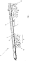
Figure 1 is a schematic and partial view of a machine according to the invention; -
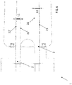
Figure 2 is an enlargement of a part ofFigure 1 ; -
Figure 3 is a schematic and partial top view, of a part of the machine according to the invention; -
Figure 4 is a cross-sectional and partial view, of a machine according to the invention, in a different embodiment; -
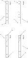
Figures 5A-5D represent as many smoking articles obtainable from a machine and from a method according to the invention. - With reference to the attached
Figures 1 ,2 and3 , a machine for producing a continuous rope of the tobacco industry (shown schematically and partially) has been designated by 1. In particular, the rope is of thetype comprising particles 3 of a first aerosol-generating material andparticles 4 of a second aerosol-generating material different from each other and arranged according to a predetermined sequence (and a predetermined profile) along the development of the rope. Theparticles - This type of machine, in particular, allows to manufacture a continuous rope intended to form pieces of articles A of the tobacco industry (for example, cigarettes) that contain, on the inside thereof, two aerosol-generating materials arranged with a predetermined profile and given sequence.
- It should be noted that with the expression "articles of the tobacco industry" we mean articles of any type pertaining to this sector, for example, traditional cigarettes or articles of the "heat not burn" (HNB) type which provide only for heating and not for combustion of the article itself.
- Some examples of these smoking articles A (in detail, cigarettes) obtainable with the machine according to the invention are illustrated in
Figures 5A-5D . - In detail, the represented smoking articles A have a longitudinal development, a first end P (or tip end) and a second end E (at which, in the illustrated example, a filter F is present).
- In
Figures 5A and 5B , theparticles 3 of the first material are arranged at the first end P of the corresponding smoking article A with different profiles from each other, whereas inFigures 5C and 5D , theparticles 3 of the first material are arranged at the second end E of the corresponding smoking article A with different profiles from each other. Conversely, inFigures 5C and 5D theparticles 4 of the second material are arranged at the first end P of the corresponding smoking article A with profiles different from each other, whereas inFigures 5A and 5B theparticles 4 of the second material are arranged at the second end E of the corresponding smoking article A with profiles different from each other. - The
machine 1 according to the invention comprises: - belt conveying means 2 having an
active branch 20 subject to suction that is movable in a conveying direction D and comprises two oppositelateral edges - a
first feeder 30 arranged below theactive branch 20 of thebelt 2 forfeeding particles 3 of the first material in afirst feeding zone 31 so that the particles are held on theactive branch 20 of thebelt 2; - a
second feeder 40 arranged below theactive branch 20 of thebelt 2 and downstream of thefirst feeder 30 along the conveying direction D, forfeeding particles 4 of the second material in asecond feeding zone 41 so that the particles are held on theactive branch 20 of thebelt 2. - In particular, the
machine 1 comprises acompactor unit 5 arranged along the conveying direction D between thefirst feeding zone 31 and thesecond feeding zone 41 and arranged to compact theparticles 3 of the first material held on theactive branch 20 of thebelt 2 by acting on oppositelateral edges active branch 20 of thebelt 2. - In other words, the
compactor unit 5 only contacts theparticles 3 of the first material and not theactive branch 20 of thebelt 2. - Namely, the compactor unit 5 compacts or acts by bringing the
particles 3 of the first material closer together (pressing them together). - Advantageously, the
compactor unit 5 allows to restore the compaction of theparticles 3 of the first material before the feeding of theparticles 4 of the second material. On the one hand, this aspect avoids machine blockages, on the other hand, it guarantees an optimal quality of the final product. - Preferably, the opposite
lateral edges active branch 20 of thebelt 2 comprise twoside walls - Preferably, the
belt 2 is configured so that theparticles 3 of the first material andparticles 4 of the second material are held on the relativeactive branch 20 according to a predetermined sequence, in particular according to an alternation between particle masses of the two materials, first 3 and second 4 with a given profile (for example, so that the articles A such as those inFigures 5A-5D can be derived therefrom). - It is specified that the term "belt conveying means 2 having an
active branch 20 subject to suction" means that theactive branch 20 may comprise through-holes (not visible in the attached Figures) sized so as to allow the passage of air, but not to allow the passage of the particles of aerosol-generating material. - For example, the suction holes, connected or connectable to the suction source, have a cross-sectional dimension of less than 1 mm, preferably less than 0.8 mm, whereas the particles of the (first and second) material have, for example, a cross-sectional dimension greater than 0.9 mm, even more preferably greater than 1 mm.
- By "active branch" 20 of the
belt 2 we mean, in this context, the branch of thebelt 2 which is operational, namely, which in this case holds theparticles 3 of the first material and theparticles 4 of the second material. - As mentioned in the introductory part, in order to avoid blockages during the advancement of the
material active branch 20 of thebelt 2, preferably the twoside walls first feeder 30 to the second feeder 40 (we are talking around differences of the order of a few millimetres). Particular reference is made toFigure 4 , where this increasing transverse width L1, L2 has been indicated by way of example in the case of twobelts 2, 2', i.e. in amachine 1 for the simultaneous manufacturing of two continuous ropes (a situation that will be described in the following) . For example, this width varies from a value L1 of approximately 6 mm to a value L2 of approximately 8 mm. - Preferably, the
compactor unit 5 comprises afirst element 51 and asecond element 52 arranged opposite to each other along the conveying direction D. - According to the preferred embodiment, the
first element 51 and thesecond element 52 are rotatable respectively around at least one first rotation axis H and at least one second rotation axis K (seeFigures 2 and3 ) passing through the same, respectively in a first rotation direction V1 and in a second rotation direction V2, which are opposite to each other (indicated only inFigure 3 ). - With reference to the attached Figures, the first rotation axis H and the second rotation axis K are substantially vertical (in any case transverse, preferably perpendicular to the conveying direction D) (see
Figure 2 , with reference to the first rotation axis H). - According to one embodiment, the
first element 51 comprises afirst roller 51 and thesecond element 52 comprises asecond roller 52. In detail, thefirst roller 51 and thesecond roller 52 are idle and are dragged into rotation in the first rotation direction V1 and in the second rotation direction V2, respectively, by the advancement of theactive branch 20 of thebelt 2 along the conveying direction D. This embodiment is of particular constructive and functional simplicity. In fact, in this way, the synchrony between the (angular speed of) rotation of thefirst roller 51 and of thesecond roller 52 with the advancement (namely the advancement speed) of theactive branch 20 of thebelt 2 along the conveying direction D is guaranteed. - According to the preferred embodiment illustrated, the
first element 51 comprises afirst roller 51 and thesecond element 52 comprises asecond roller 52; furthermore, thecompactor unit 5 further comprises motor means M (indicated only inFigure 2 ) for motorizing thefirst roller 51 and thesecond roller 52 in rotation in the first rotation direction V1 and the second rotation direction V2, respectively, during the advancement of thebelt 2 along the conveying direction D. This specification reduces friction and promotes sliding of theparticles 3 of the first material along the conveying direction D. Preferably, the (angular) speed of rotation of thefirst roller 51 and of thesecond roller 52 is synchronous with the advancement speed of theactive branch 20 of thebelt 2 along the conveying direction D. The rotation speed of thefirst roller 51 and of thesecond roller 52 also follows any variations in the speed of theparticles 3 of the first material along the conveying direction D (due, for example, to variations in production speed or to a different length of the pieces to be produced). - According to an alternative embodiment not illustrated, the
first element 51 and thesecond element 52 of thecompactor unit 5 respectively comprise a first motorized belt and a second motorized belt, arranged along the conveying direction D and having a straight and inclined (or slightly curved) profile so as to compact theparticles 3 of the first material held on theactive branch 20 of thebelt 2 by acting on the oppositelateral edges active branch 20 of thebelt 2. - In general, the
first element 51 and thesecond element 52 of thecompactor unit 5 may have a profile conformed so as to receive anyparticles 3 of the first material that should detach from theactive branch 20 of thebelt 2 during compression. In other words, the lateral surface of thefirst element 51 and of thesecond element 52 that contacts theparticles 3 of the first material may be slightly inclined or curved to receive anyparticles 3 of the first material that should detach from theactive branch 20 of the belt preventing them from falling downwards. According to an example not illustrated, thebelt conveying means 2 comprise at least a first belt and a second belt arranged in succession to each other along the conveying direction D; the first belt being arranged to receive theparticles 3 of the first material from thefirst feeder 30 and the second belt being arranged to receive theparticles 4 of the second material from thesecond feeder 40. In this case, thecompactor unit 5 is arranged between the first belt and the second belt. - Preferably, the
machine 1 further comprises at least one shaving assembly 6 (visible inFigures 1 and2 ) arranged along the conveying path at a certain distance from theactive branch 20 of thebelt 2, upstream of thecompactor unit 5. The shavingassembly 6 is configured to determine a partial removal of theparticles 3 of the first material held by theactive branch 20 of thebelt 2. The shavingassembly 6 and thebelt 2 may be movable in respective distancing and approaching, in order to vary the distance thereof. According to a variation, the shavingassembly 6 is movable away from and towards thebelt 2, which is fixed. According to a different variation, thebelt 2 is movable away from and towards the shavingassembly 6, which is fixed. According to a further variant, the shavingassembly 6 and thebelt 2 are both movable away from and towards each other in order to vary the relative distance. - Advantageously, this characteristic allows adjustment of the thickness of the mass of
particles 3 of the first material held by theactive branch 20 of thebelt 2. - A further shaving assembly (not illustrated) may be provided, arranged along the conveying direction D at a certain distance from the
belt 2, downstream of thesecond feeding zone 41, to determine partial removal of theparticles 4 of the second material held by the active branch of thebelt 2. Also in this case, the shaving assembly may be movable away from and towards thebelt 2 in order to vary the relative distance thereof. - According to a variant, the
machine 1 is arranged to produce simultaneously two continuous ropes of the tobacco industry, each comprisingparticles 3 of the first aerosol-generating material andparticles 4 of the second aerosol-generating material different from each other and arranged according to a predetermined sequence along the development of the respective rope itself. Reference is made toFigure 4 , where twobelts 2, 2' withcorresponding side walls machine 1 will provide two compactor units (not visible from the section illustrated inFigure 4 ) each dedicated to compactingparticles 3 of the first material held on the active branch of thecorresponding belt 2, 2'. - In this case, it is preferable that the compactor unit associated with each
belt 2, 2' has as small a dimension as possible: this can be achieved, for example, by using the first motorized belt and the second motorized belt mentioned above as thefirst element 51 andsecond element 52 of each compactor unit. Alternatively, the two belts may be staggered from each other in height, and thefirst roller 51 and thesecond roller 52 as described above may be provided for eachcompactor unit 5 so as not to interfere with each other. - What is mentioned above for the remaining machine parts will be suitably arranged for producing two continuous ropes of the tobacco industry.
- The present invention furthermore relates to a method for producing a continuous rope of the tobacco industry, the
latter comprising particles 3 of a first aerosol-generating material andparticles 4 of a second aerosol-generating material different from each other and arranged according to a predetermined sequence along the development of the rope. - The method comprises the steps of:
- providing belt conveying means 2 having an
active branch 20 subject to suction that is movable in a conveying direction D, comprising two opposite lateral edges 21, 22; -
feeding particles 3 of the first material in afirst feeding zone 31 so that the particles are held on theactive branch 20 of thebelt 2; -
feeding particles 4 of the second material in asecond feeding zone 41, downstream of thefirst feeding zone 31, so that the particles are held on theactive branch 20 of thebelt 2; - In particular, the method comprises the step of laterally compacting the
particles 3 of the first material between thefirst feeding zone 31 and thesecond feeding zone 41 at oppositelateral edges active branch 20 of thebelt 2. - Advantageously, the proposed method ensures the quality of the final product as it allows compaction of the
particles 3 of the first material upstream of the feeding of theparticles 4 of the second material, ensuring the correct flow of the particles without the formation of blockages. - Preferably, the compacting step is carried out by means of at least a
first element 51 and asecond element 52 arranged opposite to each other along the conveying direction D. - According to the preferred embodiment, the
first element 51 and thesecond element 52 are rotatable respectively around at least one first rotation axis H and at least one second rotation axis K (seeFigures 2 and3 ) passing through the same respectively in a first rotation direction and in a second rotation direction V2, which are opposite to each other (indicated only inFigure 3 ) . According to this embodiment, the compaction step is carried out by means of the step of bringing thefirst element 51 and thesecond element 52 into rotation in the first and second rotation directions V2, respectively. - According to an embodiment, the
first element 51 comprises a firstidle roller 51 and thesecond element 52 comprises a secondidle roller 52. In this case, the compacting step comprises the step of dragging thefirst roller 51 and thesecond roller 52 into rotation in the first rotation direction V1 and in the second rotation direction V2, respectively, with the advancement of the belt 2 (namely, its active branch 20) along the conveying direction D. This embodiment is of particular constructive and functional simplicity. - According to the preferred illustrated embodiment, the
first element 51 comprises a firstmotorized roller 51 and thesecond element 52 comprises a secondmotorized roller 52. The compacting step comprises the step of controlling the rotational activation of thefirst roller 51 and thesecond roller 52 respectively in the first rotation direction V1 and in the second rotation direction V2 simultaneously with the advancement of the belt 2 (namely, its active branch 20) along the conveying direction D. Advantageously, this specification reduces friction and promotes the sliding of theparticles 3 of the first material along the conveying direction D. - The method is preferably implemented by means of the
machine 1 as previously described. For further advantages, reference should be made to the foregoing description with reference to themachine 1.
Claims (11)
- A machine (1) for producing a continuous rope of the tobacco industry, the rope comprising particles (3) of a first aerosol-generating material and particles (4) of a second aerosol-generating material different from each other and arranged according to a predetermined sequence along the development of the rope;
the machine (1) comprises:- belt conveying means (2) having an active branch (20) subject to suction that is movable in a conveying direction (D) and comprises two opposite lateral edges (21, 22);- a first feeder (30) arranged below the active branch (20) of the belt (2) for feeding particles (3) of the first material in a first feeding zone (31) so that the particles (3) are held on the active branch (20) of the belt (2); and- a second feeder (40) arranged below the active branch (20) of the belt (2) and downstream of the first feeder (30) along the conveying direction (D) for feeding particles (4) of the second material in a second feeding zone (41) so that the particles (4) are held on the active branch (20) of the belt (2);characterized in that it comprises a compactor unit (5) arranged along the conveying direction (D) between the first feeding zone (31) and the second feeding zone (41) and arranged to compact the particles (3) of the first material held on the active branch (20) of the belt (2) by acting on the opposite lateral edges (21, 22) of the active branch (20) of the belt (2). - The machine (1) according to the preceding claim, wherein the compactor unit (5) comprises a first element (51) and a second element (52) arranged opposite to each other along the conveying direction (D) .
- The machine (1) according to the preceding claim, wherein the first element (51) and the second element (52) are rotatable respectively around at least a first rotation axis (H) and at least a second rotation axis (K) passing through them respectively in a first rotation direction (VI) and in a second rotation direction (V2), opposite to each other.
- The machine (1) according to the preceding claim, wherein the first element (51) comprises a first roller (51) and the second element (52) comprises a second roller (52); the first roller (51) and the second roller (52) being idle and dragged into rotation respectively in the first rotation direction (VI) and in the second rotation direction (V2) by the advancement of the active branch (20) of the belt (2) along the conveying direction (D).
- The machine (1) according to claim 3, wherein the first element (51) comprises a first roller (51) and the second element (52) comprises a second roller (52); the compactor unit (5) further comprises motor means (M) for motorizing the first roller (51) and the second roller (52) into rotation respectively in the first rotation direction (VI) and in the second rotation direction (V2) during the advancement of the active branch (20) of the belt (2) along the conveying direction (D).
- The machine (1) according to any one of the preceding claims, wherein the belt conveying means (2) comprises at least a first belt and a second belt arranged in succession to each other along the conveying direction (D); the first belt being arranged to receive the particles (3) of the first material from the first feeder (30) and the second belt being arranged to receive particles (4) of the second material from the second feeder (40); and in which the compactor unit (5) is arranged between the first belt and the second belt.
- A method for producing a continuous rope of the tobacco industry, the rope comprising particles (3) of a first aerosol-generating material and particles (4) of a second aerosol-generating material different from each other and arranged according to a predetermined sequence along the development of the rope;
the method comprises the steps of:- providing belt conveying means (2) having an active branch (20) subject to suction that is movable in a conveying direction (D) and comprising two opposite lateral edges (21, 22);- feeding in a first feeding zone (31) particles (3) of the first material so that the particles (3) are held on the active branch (20) of the belt (2); and- feeding in a second feeding zone (41), downstream of the first feeding zone (31), particles (4) of the second material so that the particles (4) are held by the active branch (20) of the belt (2); characterized in that it further comprises the step of laterally compacting the particles (3) of the first material between the first feeding zone (31) and the second feeding zone (41), on the opposite lateral edges (21, 22) of the active branch (20) of the belt (2). - The method according to the preceding claim, wherein the compacting step is carried out by at least a first element (51) and a second element (52) arranged opposite to each other along the conveying direction (D).
- The method according to claim 8, wherein the first element (51) and the second element (52) are rotatable respectively around at least a first rotation axis (H) and at least a second rotation axis (K) passing through them respectively in a first rotation direction (VI) and in a second rotation direction (V2), opposite to each other, and wherein the compacting step is carried out by the step of bringing the first element (51) and the second element (52) into rotation respectively in the first rotation direction (VI) and in the second rotation direction (V2) .
- The method according to claim 9, wherein the first element (51) comprises a first roller (51) and the second element (52) comprises a second roller (52), the first roller (51) and the second roller (52) being idle; and wherein the compacting step comprises the step of dragging the first roller (51) and the second roller (52) into rotation respectively in the first rotation direction (VI) and in the second rotation direction (V2) by the advancement of the active branch (20) of the belt (2) along the conveying direction (D).
- The method according to claim 9 (10?), wherein the first element (51) comprises a first roller (51) and the second element (52) comprises a second roller (52), the first roller (51) and the second roller (52) being motorized; and wherein the compacting step comprises the step of activating the rotation of the first roller (51) and the second roller (52) respectively in the first rotation direction (VI) and in the second rotation direction (V2) during the advancement of the active branch (20) of the belt (2) along the conveying direction (D) .
Applications Claiming Priority (1)
| Application Number | Priority Date | Filing Date | Title |
|---|---|---|---|
| IT102021000009083A IT202100009083A1 (en) | 2021-04-12 | 2021-04-12 | MACHINE AND METHOD FOR THE PRODUCTION OF A CONTINUOUS BEAD OF THE TOBACCO INDUSTRY |
Publications (3)
| Publication Number | Publication Date |
|---|---|
| EP4074193A1 true EP4074193A1 (en) | 2022-10-19 |
| EP4074193A8 EP4074193A8 (en) | 2023-05-17 |
| EP4074193B1 EP4074193B1 (en) | 2024-02-21 |
Family
ID=77519449
Family Applications (1)
| Application Number | Title | Priority Date | Filing Date |
|---|---|---|---|
| EP22167415.3A Active EP4074193B1 (en) | 2021-04-12 | 2022-04-08 | Machine and method for producing a continuous rope of the tobacco industry |
Country Status (3)
| Country | Link |
|---|---|
| EP (1) | EP4074193B1 (en) |
| IT (1) | IT202100009083A1 (en) |
| PL (1) | PL4074193T3 (en) |
Citations (2)
| Publication number | Priority date | Publication date | Assignee | Title |
|---|---|---|---|---|
| GB2182541A (en) * | 1985-11-19 | 1987-05-20 | Gd Spa | Method for producing cigarettes containing at least two different tobacco mixtures |
| WO2020201682A1 (en) | 2019-04-03 | 2020-10-08 | British American Tobacco (Investments) Limited | Apparatus for manufacturing a rod of aerosolisable material and method of manufacturing a rod of aerosolisable material |
-
2021
- 2021-04-12 IT IT102021000009083A patent/IT202100009083A1/en unknown
-
2022
- 2022-04-08 EP EP22167415.3A patent/EP4074193B1/en active Active
- 2022-04-08 PL PL22167415.3T patent/PL4074193T3/en unknown
Patent Citations (2)
| Publication number | Priority date | Publication date | Assignee | Title |
|---|---|---|---|---|
| GB2182541A (en) * | 1985-11-19 | 1987-05-20 | Gd Spa | Method for producing cigarettes containing at least two different tobacco mixtures |
| WO2020201682A1 (en) | 2019-04-03 | 2020-10-08 | British American Tobacco (Investments) Limited | Apparatus for manufacturing a rod of aerosolisable material and method of manufacturing a rod of aerosolisable material |
Also Published As
| Publication number | Publication date |
|---|---|
| EP4074193B1 (en) | 2024-02-21 |
| PL4074193T3 (en) | 2024-05-13 |
| IT202100009083A1 (en) | 2022-10-12 |
| EP4074193A8 (en) | 2023-05-17 |
Similar Documents
| Publication | Publication Date | Title |
|---|---|---|
| US2660178A (en) | Formation of the roll of tobacco in cigarette-making machines | |
| EP0251138B1 (en) | Process and corresponding machine for the production by continuous rolling of a mass of dough for bakery products and buns and rolls | |
| US3957062A (en) | Cigarette making machines | |
| US2852987A (en) | Process and machine for producing rods for tobacco filters | |
| US3315685A (en) | Method of producing a continuous tobacco rod | |
| US20010052346A1 (en) | A process of feeding a tobacco stream, a hopper and a machine equipped with a hopper | |
| EP4074193B1 (en) | Machine and method for producing a continuous rope of the tobacco industry | |
| EP2560510B1 (en) | Tobacco rod manufacturing apparatus | |
| JPH07155158A (en) | Device for removing excessive amount of tobacco from continuous tobacco body | |
| US20040250823A1 (en) | Method and machine for producing a continuous filter rod | |
| WO2020201682A1 (en) | Apparatus for manufacturing a rod of aerosolisable material and method of manufacturing a rod of aerosolisable material | |
| US4589426A (en) | Continuous-rod cigarette manufacturing machine | |
| JP2840302B2 (en) | Cigarette making machine and method for producing cigarette | |
| US4703764A (en) | Method and apparatus for making rod-like fillers from several types of fibrous material | |
| US4732164A (en) | Method of and apparatus for making a continuous filler of tobacco or the like | |
| US4693262A (en) | Apparatus for forming batches of tobacco and the like | |
| WO2000054611A1 (en) | Trimming device | |
| CA1144032A (en) | Feed mechanism for tobacco cutting machines | |
| JPS6244160A (en) | Apparatus for producing fiber rod used for processing tobacco | |
| US3413979A (en) | Continuous cigarette rod-making machine | |
| IT8319022A1 (en) | FEEDING TOBACCO BY CUTTING MACHINES - III | |
| US3645273A (en) | Method and apparatus for making fillers of fibrous material | |
| US3234950A (en) | Cigarette making machine | |
| US3316917A (en) | Device for producing a continuous tobacco rod of uniform cross section | |
| WO2020201681A1 (en) | Apparatus for manufacturing a rod of aerosolisable material and method of manufacturing a rod of aerosolisable material |
Legal Events
| Date | Code | Title | Description |
|---|---|---|---|
| PUAI | Public reference made under article 153(3) epc to a published international application that has entered the european phase |
Free format text: ORIGINAL CODE: 0009012 |
|
| STAA | Information on the status of an ep patent application or granted ep patent |
Free format text: STATUS: THE APPLICATION HAS BEEN PUBLISHED |
|
| AK | Designated contracting states |
Kind code of ref document: A1 Designated state(s): AL AT BE BG CH CY CZ DE DK EE ES FI FR GB GR HR HU IE IS IT LI LT LU LV MC MK MT NL NO PL PT RO RS SE SI SK SM TR |
|
| STAA | Information on the status of an ep patent application or granted ep patent |
Free format text: STATUS: REQUEST FOR EXAMINATION WAS MADE |
|
| 17P | Request for examination filed |
Effective date: 20230322 |
|
| RBV | Designated contracting states (corrected) |
Designated state(s): AL AT BE BG CH CY CZ DE DK EE ES FI FR GB GR HR HU IE IS IT LI LT LU LV MC MK MT NL NO PL PT RO RS SE SI SK SM TR |
|
| P01 | Opt-out of the competence of the unified patent court (upc) registered |
Effective date: 20230529 |
|
| GRAP | Despatch of communication of intention to grant a patent |
Free format text: ORIGINAL CODE: EPIDOSNIGR1 |
|
| STAA | Information on the status of an ep patent application or granted ep patent |
Free format text: STATUS: GRANT OF PATENT IS INTENDED |
|
| RIC1 | Information provided on ipc code assigned before grant |
Ipc: A24C 5/18 20060101AFI20230830BHEP |
|
| INTG | Intention to grant announced |
Effective date: 20230919 |
|
| GRAS | Grant fee paid |
Free format text: ORIGINAL CODE: EPIDOSNIGR3 |
|
| GRAA | (expected) grant |
Free format text: ORIGINAL CODE: 0009210 |
|
| STAA | Information on the status of an ep patent application or granted ep patent |
Free format text: STATUS: THE PATENT HAS BEEN GRANTED |
|
| AK | Designated contracting states |
Kind code of ref document: B1 Designated state(s): AL AT BE BG CH CY CZ DE DK EE ES FI FR GB GR HR HU IE IS IT LI LT LU LV MC MK MT NL NO PL PT RO RS SE SI SK SM TR |
|
| REG | Reference to a national code |
Ref country code: GB Ref legal event code: FG4D |
|
| REG | Reference to a national code |
Ref country code: CH Ref legal event code: EP |
|
| REG | Reference to a national code |
Ref country code: DE Ref legal event code: R096 Ref document number: 602022001999 Country of ref document: DE |
|
| REG | Reference to a national code |
Ref country code: IE Ref legal event code: FG4D |
|
| REG | Reference to a national code |
Ref country code: LT Ref legal event code: MG9D |
|
| REG | Reference to a national code |
Ref country code: NL Ref legal event code: MP Effective date: 20240221 |
|
| PG25 | Lapsed in a contracting state [announced via postgrant information from national office to epo] |
Ref country code: IS Free format text: LAPSE BECAUSE OF FAILURE TO SUBMIT A TRANSLATION OF THE DESCRIPTION OR TO PAY THE FEE WITHIN THE PRESCRIBED TIME-LIMIT Effective date: 20240621 |
|
| PG25 | Lapsed in a contracting state [announced via postgrant information from national office to epo] |
Ref country code: LT Free format text: LAPSE BECAUSE OF FAILURE TO SUBMIT A TRANSLATION OF THE DESCRIPTION OR TO PAY THE FEE WITHIN THE PRESCRIBED TIME-LIMIT Effective date: 20240221 |
|
| PG25 | Lapsed in a contracting state [announced via postgrant information from national office to epo] |
Ref country code: GR Free format text: LAPSE BECAUSE OF FAILURE TO SUBMIT A TRANSLATION OF THE DESCRIPTION OR TO PAY THE FEE WITHIN THE PRESCRIBED TIME-LIMIT Effective date: 20240522 |
|
| REG | Reference to a national code |
Ref country code: AT Ref legal event code: MK05 Ref document number: 1658270 Country of ref document: AT Kind code of ref document: T Effective date: 20240221 |
|
| PG25 | Lapsed in a contracting state [announced via postgrant information from national office to epo] |
Ref country code: RS Free format text: LAPSE BECAUSE OF FAILURE TO SUBMIT A TRANSLATION OF THE DESCRIPTION OR TO PAY THE FEE WITHIN THE PRESCRIBED TIME-LIMIT Effective date: 20240521 Ref country code: HR Free format text: LAPSE BECAUSE OF FAILURE TO SUBMIT A TRANSLATION OF THE DESCRIPTION OR TO PAY THE FEE WITHIN THE PRESCRIBED TIME-LIMIT Effective date: 20240221 Ref country code: NL Free format text: LAPSE BECAUSE OF FAILURE TO SUBMIT A TRANSLATION OF THE DESCRIPTION OR TO PAY THE FEE WITHIN THE PRESCRIBED TIME-LIMIT Effective date: 20240221 |
|
| PG25 | Lapsed in a contracting state [announced via postgrant information from national office to epo] |
Ref country code: ES Free format text: LAPSE BECAUSE OF FAILURE TO SUBMIT A TRANSLATION OF THE DESCRIPTION OR TO PAY THE FEE WITHIN THE PRESCRIBED TIME-LIMIT Effective date: 20240221 |
|
| PG25 | Lapsed in a contracting state [announced via postgrant information from national office to epo] |
Ref country code: AT Free format text: LAPSE BECAUSE OF FAILURE TO SUBMIT A TRANSLATION OF THE DESCRIPTION OR TO PAY THE FEE WITHIN THE PRESCRIBED TIME-LIMIT Effective date: 20240221 |
|
| PG25 | Lapsed in a contracting state [announced via postgrant information from national office to epo] |
Ref country code: RS Free format text: LAPSE BECAUSE OF FAILURE TO SUBMIT A TRANSLATION OF THE DESCRIPTION OR TO PAY THE FEE WITHIN THE PRESCRIBED TIME-LIMIT Effective date: 20240521 Ref country code: NO Free format text: LAPSE BECAUSE OF FAILURE TO SUBMIT A TRANSLATION OF THE DESCRIPTION OR TO PAY THE FEE WITHIN THE PRESCRIBED TIME-LIMIT Effective date: 20240521 Ref country code: NL Free format text: LAPSE BECAUSE OF FAILURE TO SUBMIT A TRANSLATION OF THE DESCRIPTION OR TO PAY THE FEE WITHIN THE PRESCRIBED TIME-LIMIT Effective date: 20240221 Ref country code: LT Free format text: LAPSE BECAUSE OF FAILURE TO SUBMIT A TRANSLATION OF THE DESCRIPTION OR TO PAY THE FEE WITHIN THE PRESCRIBED TIME-LIMIT Effective date: 20240221 Ref country code: IS Free format text: LAPSE BECAUSE OF FAILURE TO SUBMIT A TRANSLATION OF THE DESCRIPTION OR TO PAY THE FEE WITHIN THE PRESCRIBED TIME-LIMIT Effective date: 20240621 Ref country code: HR Free format text: LAPSE BECAUSE OF FAILURE TO SUBMIT A TRANSLATION OF THE DESCRIPTION OR TO PAY THE FEE WITHIN THE PRESCRIBED TIME-LIMIT Effective date: 20240221 Ref country code: GR Free format text: LAPSE BECAUSE OF FAILURE TO SUBMIT A TRANSLATION OF THE DESCRIPTION OR TO PAY THE FEE WITHIN THE PRESCRIBED TIME-LIMIT Effective date: 20240522 Ref country code: FI Free format text: LAPSE BECAUSE OF FAILURE TO SUBMIT A TRANSLATION OF THE DESCRIPTION OR TO PAY THE FEE WITHIN THE PRESCRIBED TIME-LIMIT Effective date: 20240221 Ref country code: ES Free format text: LAPSE BECAUSE OF FAILURE TO SUBMIT A TRANSLATION OF THE DESCRIPTION OR TO PAY THE FEE WITHIN THE PRESCRIBED TIME-LIMIT Effective date: 20240221 Ref country code: BG Free format text: LAPSE BECAUSE OF FAILURE TO SUBMIT A TRANSLATION OF THE DESCRIPTION OR TO PAY THE FEE WITHIN THE PRESCRIBED TIME-LIMIT Effective date: 20240221 Ref country code: AT Free format text: LAPSE BECAUSE OF FAILURE TO SUBMIT A TRANSLATION OF THE DESCRIPTION OR TO PAY THE FEE WITHIN THE PRESCRIBED TIME-LIMIT Effective date: 20240221 |
|
| PG25 | Lapsed in a contracting state [announced via postgrant information from national office to epo] |
Ref country code: PT Free format text: LAPSE BECAUSE OF FAILURE TO SUBMIT A TRANSLATION OF THE DESCRIPTION OR TO PAY THE FEE WITHIN THE PRESCRIBED TIME-LIMIT Effective date: 20240621 |
|
| PG25 | Lapsed in a contracting state [announced via postgrant information from national office to epo] |
Ref country code: SE Free format text: LAPSE BECAUSE OF FAILURE TO SUBMIT A TRANSLATION OF THE DESCRIPTION OR TO PAY THE FEE WITHIN THE PRESCRIBED TIME-LIMIT Effective date: 20240221 Ref country code: PT Free format text: LAPSE BECAUSE OF FAILURE TO SUBMIT A TRANSLATION OF THE DESCRIPTION OR TO PAY THE FEE WITHIN THE PRESCRIBED TIME-LIMIT Effective date: 20240621 Ref country code: LV Free format text: LAPSE BECAUSE OF FAILURE TO SUBMIT A TRANSLATION OF THE DESCRIPTION OR TO PAY THE FEE WITHIN THE PRESCRIBED TIME-LIMIT Effective date: 20240221 |
|
| PG25 | Lapsed in a contracting state [announced via postgrant information from national office to epo] |
Ref country code: DK Free format text: LAPSE BECAUSE OF FAILURE TO SUBMIT A TRANSLATION OF THE DESCRIPTION OR TO PAY THE FEE WITHIN THE PRESCRIBED TIME-LIMIT Effective date: 20240221 |
|
| PG25 | Lapsed in a contracting state [announced via postgrant information from national office to epo] |
Ref country code: SM Free format text: LAPSE BECAUSE OF FAILURE TO SUBMIT A TRANSLATION OF THE DESCRIPTION OR TO PAY THE FEE WITHIN THE PRESCRIBED TIME-LIMIT Effective date: 20240221 |
|
| PG25 | Lapsed in a contracting state [announced via postgrant information from national office to epo] |
Ref country code: EE Free format text: LAPSE BECAUSE OF FAILURE TO SUBMIT A TRANSLATION OF THE DESCRIPTION OR TO PAY THE FEE WITHIN THE PRESCRIBED TIME-LIMIT Effective date: 20240221 Ref country code: CZ Free format text: LAPSE BECAUSE OF FAILURE TO SUBMIT A TRANSLATION OF THE DESCRIPTION OR TO PAY THE FEE WITHIN THE PRESCRIBED TIME-LIMIT Effective date: 20240221 |
|
| PG25 | Lapsed in a contracting state [announced via postgrant information from national office to epo] |
Ref country code: SK Free format text: LAPSE BECAUSE OF FAILURE TO SUBMIT A TRANSLATION OF THE DESCRIPTION OR TO PAY THE FEE WITHIN THE PRESCRIBED TIME-LIMIT Effective date: 20240221 |
|
| PG25 | Lapsed in a contracting state [announced via postgrant information from national office to epo] |
Ref country code: SM Free format text: LAPSE BECAUSE OF FAILURE TO SUBMIT A TRANSLATION OF THE DESCRIPTION OR TO PAY THE FEE WITHIN THE PRESCRIBED TIME-LIMIT Effective date: 20240221 Ref country code: SK Free format text: LAPSE BECAUSE OF FAILURE TO SUBMIT A TRANSLATION OF THE DESCRIPTION OR TO PAY THE FEE WITHIN THE PRESCRIBED TIME-LIMIT Effective date: 20240221 Ref country code: RO Free format text: LAPSE BECAUSE OF FAILURE TO SUBMIT A TRANSLATION OF THE DESCRIPTION OR TO PAY THE FEE WITHIN THE PRESCRIBED TIME-LIMIT Effective date: 20240221 Ref country code: EE Free format text: LAPSE BECAUSE OF FAILURE TO SUBMIT A TRANSLATION OF THE DESCRIPTION OR TO PAY THE FEE WITHIN THE PRESCRIBED TIME-LIMIT Effective date: 20240221 Ref country code: DK Free format text: LAPSE BECAUSE OF FAILURE TO SUBMIT A TRANSLATION OF THE DESCRIPTION OR TO PAY THE FEE WITHIN THE PRESCRIBED TIME-LIMIT Effective date: 20240221 Ref country code: CZ Free format text: LAPSE BECAUSE OF FAILURE TO SUBMIT A TRANSLATION OF THE DESCRIPTION OR TO PAY THE FEE WITHIN THE PRESCRIBED TIME-LIMIT Effective date: 20240221 |
|
| PG25 | Lapsed in a contracting state [announced via postgrant information from national office to epo] |
Ref country code: MC Free format text: LAPSE BECAUSE OF FAILURE TO SUBMIT A TRANSLATION OF THE DESCRIPTION OR TO PAY THE FEE WITHIN THE PRESCRIBED TIME-LIMIT Effective date: 20240221 |
|
| REG | Reference to a national code |
Ref country code: DE Ref legal event code: R097 Ref document number: 602022001999 Country of ref document: DE |
|
| PG25 | Lapsed in a contracting state [announced via postgrant information from national office to epo] |
Ref country code: MC Free format text: LAPSE BECAUSE OF FAILURE TO SUBMIT A TRANSLATION OF THE DESCRIPTION OR TO PAY THE FEE WITHIN THE PRESCRIBED TIME-LIMIT Effective date: 20240221 |
|
| PG25 | Lapsed in a contracting state [announced via postgrant information from national office to epo] |
Ref country code: IT Free format text: LAPSE BECAUSE OF FAILURE TO SUBMIT A TRANSLATION OF THE DESCRIPTION OR TO PAY THE FEE WITHIN THE PRESCRIBED TIME-LIMIT Effective date: 20240221 |
|
| PG25 | Lapsed in a contracting state [announced via postgrant information from national office to epo] |
Ref country code: LU Free format text: LAPSE BECAUSE OF NON-PAYMENT OF DUE FEES Effective date: 20240408 |
|
| PLBE | No opposition filed within time limit |
Free format text: ORIGINAL CODE: 0009261 |
|
| STAA | Information on the status of an ep patent application or granted ep patent |
Free format text: STATUS: NO OPPOSITION FILED WITHIN TIME LIMIT |
|
| REG | Reference to a national code |
Ref country code: BE Ref legal event code: MM Effective date: 20240430 |
|
| PG25 | Lapsed in a contracting state [announced via postgrant information from national office to epo] |
Ref country code: LU Free format text: LAPSE BECAUSE OF NON-PAYMENT OF DUE FEES Effective date: 20240408 Ref country code: IT Free format text: LAPSE BECAUSE OF FAILURE TO SUBMIT A TRANSLATION OF THE DESCRIPTION OR TO PAY THE FEE WITHIN THE PRESCRIBED TIME-LIMIT Effective date: 20240221 |
|
| PG25 | Lapsed in a contracting state [announced via postgrant information from national office to epo] |
Ref country code: BE Free format text: LAPSE BECAUSE OF NON-PAYMENT OF DUE FEES Effective date: 20240430 |
|
| 26N | No opposition filed |
Effective date: 20241122 |
|
| PG25 | Lapsed in a contracting state [announced via postgrant information from national office to epo] |
Ref country code: BE Free format text: LAPSE BECAUSE OF NON-PAYMENT OF DUE FEES Effective date: 20240430 |
|
| PG25 | Lapsed in a contracting state [announced via postgrant information from national office to epo] |
Ref country code: IE Free format text: LAPSE BECAUSE OF NON-PAYMENT OF DUE FEES Effective date: 20240408 |
|
| PG25 | Lapsed in a contracting state [announced via postgrant information from national office to epo] |
Ref country code: SI Free format text: LAPSE BECAUSE OF FAILURE TO SUBMIT A TRANSLATION OF THE DESCRIPTION OR TO PAY THE FEE WITHIN THE PRESCRIBED TIME-LIMIT Effective date: 20240221 |
|
| PGFP | Annual fee paid to national office [announced via postgrant information from national office to epo] |
Ref country code: PL Payment date: 20250319 Year of fee payment: 4 |
|
| PGFP | Annual fee paid to national office [announced via postgrant information from national office to epo] |
Ref country code: DE Payment date: 20250429 Year of fee payment: 4 |
|
| PGFP | Annual fee paid to national office [announced via postgrant information from national office to epo] |
Ref country code: FR Payment date: 20250425 Year of fee payment: 4 |
|
| PG25 | Lapsed in a contracting state [announced via postgrant information from national office to epo] |
Ref country code: CY Free format text: LAPSE BECAUSE OF FAILURE TO SUBMIT A TRANSLATION OF THE DESCRIPTION OR TO PAY THE FEE WITHIN THE PRESCRIBED TIME-LIMIT; INVALID AB INITIO Effective date: 20220408 |
|
| PG25 | Lapsed in a contracting state [announced via postgrant information from national office to epo] |
Ref country code: HU Free format text: LAPSE BECAUSE OF FAILURE TO SUBMIT A TRANSLATION OF THE DESCRIPTION OR TO PAY THE FEE WITHIN THE PRESCRIBED TIME-LIMIT; INVALID AB INITIO Effective date: 20220408 |
|
| REG | Reference to a national code |
Ref country code: CH Ref legal event code: H13 Free format text: ST27 STATUS EVENT CODE: U-0-0-H10-H13 (AS PROVIDED BY THE NATIONAL OFFICE) Effective date: 20251125 |
|
| PG25 | Lapsed in a contracting state [announced via postgrant information from national office to epo] |
Ref country code: CH Free format text: LAPSE BECAUSE OF NON-PAYMENT OF DUE FEES Effective date: 20250430 |