EP4074173A1 - Illuminable ball - Google Patents
Illuminable ball Download PDFInfo
- Publication number
- EP4074173A1 EP4074173A1 EP21213276.5A EP21213276A EP4074173A1 EP 4074173 A1 EP4074173 A1 EP 4074173A1 EP 21213276 A EP21213276 A EP 21213276A EP 4074173 A1 EP4074173 A1 EP 4074173A1
- Authority
- EP
- European Patent Office
- Prior art keywords
- ball
- illuminable
- latch
- cover means
- inner latch
- Prior art date
- Legal status (The legal status is an assumption and is not a legal conclusion. Google has not performed a legal analysis and makes no representation as to the accuracy of the status listed.)
- Granted
Links
Images




Classifications
-
- A—HUMAN NECESSITIES
- A01—AGRICULTURE; FORESTRY; ANIMAL HUSBANDRY; HUNTING; TRAPPING; FISHING
- A01K—ANIMAL HUSBANDRY; AVICULTURE; APICULTURE; PISCICULTURE; FISHING; REARING OR BREEDING ANIMALS, NOT OTHERWISE PROVIDED FOR; NEW BREEDS OF ANIMALS
- A01K15/00—Devices for taming animals, e.g. nose-rings or hobbles; Devices for overturning animals in general; Training or exercising equipment; Covering boxes
- A01K15/02—Training or exercising equipment, e.g. mazes or labyrinths for animals ; Electric shock devices; Toys specially adapted for animals
- A01K15/025—Toys specially adapted for animals
- A01K15/026—Chewable toys, e.g. for dental care of pets
-
- A—HUMAN NECESSITIES
- A63—SPORTS; GAMES; AMUSEMENTS
- A63B—APPARATUS FOR PHYSICAL TRAINING, GYMNASTICS, SWIMMING, CLIMBING, OR FENCING; BALL GAMES; TRAINING EQUIPMENT
- A63B39/00—Hollow non-inflatable balls, i.e. having no valves
-
- A—HUMAN NECESSITIES
- A63—SPORTS; GAMES; AMUSEMENTS
- A63B—APPARATUS FOR PHYSICAL TRAINING, GYMNASTICS, SWIMMING, CLIMBING, OR FENCING; BALL GAMES; TRAINING EQUIPMENT
- A63B43/00—Balls with special arrangements
- A63B43/06—Balls with special arrangements with illuminating devices ; with reflective surfaces
-
- F—MECHANICAL ENGINEERING; LIGHTING; HEATING; WEAPONS; BLASTING
- F21—LIGHTING
- F21L—LIGHTING DEVICES OR SYSTEMS THEREOF, BEING PORTABLE OR SPECIALLY ADAPTED FOR TRANSPORTATION
- F21L4/00—Electric lighting devices with self-contained electric batteries or cells
-
- F—MECHANICAL ENGINEERING; LIGHTING; HEATING; WEAPONS; BLASTING
- F21—LIGHTING
- F21L—LIGHTING DEVICES OR SYSTEMS THEREOF, BEING PORTABLE OR SPECIALLY ADAPTED FOR TRANSPORTATION
- F21L4/00—Electric lighting devices with self-contained electric batteries or cells
- F21L4/04—Electric lighting devices with self-contained electric batteries or cells characterised by the provision of a light source housing portion adjustably fixed to the remainder of the device
-
- F—MECHANICAL ENGINEERING; LIGHTING; HEATING; WEAPONS; BLASTING
- F21—LIGHTING
- F21V—FUNCTIONAL FEATURES OR DETAILS OF LIGHTING DEVICES OR SYSTEMS THEREOF; STRUCTURAL COMBINATIONS OF LIGHTING DEVICES WITH OTHER ARTICLES, NOT OTHERWISE PROVIDED FOR
- F21V3/00—Globes; Bowls; Cover glasses
- F21V3/04—Globes; Bowls; Cover glasses characterised by materials, surface treatments or coatings
- F21V3/049—Patterns or structured surfaces for diffusing light, e.g. frosted surfaces
-
- F—MECHANICAL ENGINEERING; LIGHTING; HEATING; WEAPONS; BLASTING
- F21—LIGHTING
- F21V—FUNCTIONAL FEATURES OR DETAILS OF LIGHTING DEVICES OR SYSTEMS THEREOF; STRUCTURAL COMBINATIONS OF LIGHTING DEVICES WITH OTHER ARTICLES, NOT OTHERWISE PROVIDED FOR
- F21V3/00—Globes; Bowls; Cover glasses
- F21V3/04—Globes; Bowls; Cover glasses characterised by materials, surface treatments or coatings
- F21V3/06—Globes; Bowls; Cover glasses characterised by materials, surface treatments or coatings characterised by the material
- F21V3/062—Globes; Bowls; Cover glasses characterised by materials, surface treatments or coatings characterised by the material the material being plastics
- F21V3/0625—Globes; Bowls; Cover glasses characterised by materials, surface treatments or coatings characterised by the material the material being plastics the material diffusing light, e.g. translucent plastics
-
- A—HUMAN NECESSITIES
- A01—AGRICULTURE; FORESTRY; ANIMAL HUSBANDRY; HUNTING; TRAPPING; FISHING
- A01K—ANIMAL HUSBANDRY; AVICULTURE; APICULTURE; PISCICULTURE; FISHING; REARING OR BREEDING ANIMALS, NOT OTHERWISE PROVIDED FOR; NEW BREEDS OF ANIMALS
- A01K15/00—Devices for taming animals, e.g. nose-rings or hobbles; Devices for overturning animals in general; Training or exercising equipment; Covering boxes
- A01K15/02—Training or exercising equipment, e.g. mazes or labyrinths for animals ; Electric shock devices; Toys specially adapted for animals
- A01K15/025—Toys specially adapted for animals
-
- A—HUMAN NECESSITIES
- A63—SPORTS; GAMES; AMUSEMENTS
- A63B—APPARATUS FOR PHYSICAL TRAINING, GYMNASTICS, SWIMMING, CLIMBING, OR FENCING; BALL GAMES; TRAINING EQUIPMENT
- A63B2225/00—Miscellaneous features of sport apparatus, devices or equipment
- A63B2225/74—Miscellaneous features of sport apparatus, devices or equipment with powered illuminating means, e.g. lights
-
- F—MECHANICAL ENGINEERING; LIGHTING; HEATING; WEAPONS; BLASTING
- F21—LIGHTING
- F21Y—INDEXING SCHEME ASSOCIATED WITH SUBCLASSES F21K, F21L, F21S and F21V, RELATING TO THE FORM OR THE KIND OF THE LIGHT SOURCES OR OF THE COLOUR OF THE LIGHT EMITTED
- F21Y2115/00—Light-generating elements of semiconductor light sources
- F21Y2115/10—Light-emitting diodes [LED]
Definitions
- This invention relates to an illuminable ball, particularly, although not exclusively, to a ball that is intended for the pet market, especially for dogs. It is well known that dogs enjoy chasing and fetching balls and by arranging a ball to be illuminated, the likelihood of it being lost, especially at night, is reduced.
- Known illuminated balls tend to be of three main types:
- the present invention seeks to provide an exercise ball for pets which is illuminable and in which the foregoing problems are substantially mitigated.
- an illuminable ball including a translucent spherical hollow casing in which is housed illumination means comprising at least one LED and control means arranged to illuminate said at least one LED; and cover means providing access to the illumination means inside said hollow casing; wherein said cover means is attached to said casing by a child-resistant closure or low reverse torque closure assembly.
- the low reverse torque closure assembly comprises a closure requiring the simultaneous application of a linear force along an axis together with a rotation about said axis in a removal direction to remove the cover from the hollow casing. More preferably the linear force is a downward force (directed towards the ball) and the removal direction is the counter-clockwise direction.
- Child-resistant closures are closures that discourage unauthorised opening by requiring the combination of simultaneous actions - usually pressing downwards or lifting upwards combined with a rotation.
- the downward or upward linear force brings nested inner and outer members into engagement so that rotation in a removal direction (usually the counter-clockwise direction) removes the cover.
- Child resistant closures can also be described as low or negligible reverse torque closures since they comprise a ratcheting assembly that provides negligible reverse torque during undepressed counter-clockwise rotation of the outer member.
- the torque caused by frictional contact of outer and inner members when the undepressed closure is turned in the counter-clockwise direction being low or negligible in the sense that it is insufficient to cause removal of the cover from the closure.
- the low reverse torque closure assembly includes an inner latch formed by an internally screw threaded cylindrical first member which is concentrically retained to be captive within an outer latch formed by a cylindrical second member having a base upon which are formed first ratchet teeth abutting with spring which is embedded into the centre of the base (as shown in figure 4 (a) ) which means on a facing wall of the first member when the inner latch is turned in a first direction to rotate the inner latch into the outer latch, causing the internal screw threads on the cylindrical first member to cooperate with mating threads on the cover means to securely close said hollow casing; and the central spring pushing an upwards force up and over the ramp means with negligible back ratchet torque when the inner latch is turned in a second direction opposite to said first direction without the application of a downforce by virtue of the central spring member disposed in the base of the second member so as to form a space between the first and second members until a downward force against the at least one spring member is applied on the inner latch and a torque simultaneously applied on the inner latch cause
- said ramp means define a low friction surface during undepressed counter-clockwise rotation of the cover means and a contact area during clockwise rotation of the cover means.
- the second ratchet teeth define a contact area for removal of the cover means from the hollow casing when the cover means is depressed.
- a slot is provided in an outer surface of said cover means for insertion of a removal implement arranged to provide said downward force and a twisting torque.
- said cover means comprises a cap in which said slot is located and said cap is matingly secured to a housing within which is mounted said control means, said housing having an external screw thread arranged to mate with the internal screw thread of the cylindrical first member.
- said control means includes an inertial switch which is normally closed, but which is arranged to open upon activation by a predetermined G-force to permit a power source to energise said at least one LED.
- said power source is at least one battery cell which is accessed by rotating the cover means in said second direction and applying a downward force to lock the inner and outer latches together so that a combination of cap and housing may be unscrewed from the inner latch, whereas without the application of a downward force, the inner latch rotatably slides over the outer latch.
- the illuminable ball has a translucent spherical hollow housing 1 made from, for example, silicone or thermoplastic rubber (TPR) having a textured and patterned outer surface.
- the housing has an opening through and in which is located the series connection of an outer latch 3, an inner latch 4 which is retained within the outer latch 3, a housing 5 and a cap 6.
- the inner latch 3 has an internal screw thread which mates with an external screw thread on the housing 5 which is arranged to mount a power source and electrical circuitry for illuminating at least one LED.
- the cap 6 is arranged to be a push fit and is secured over an end of the housing remote from the external screw thread.
- the cap has a partially diametrically extending slot 7 for insertion of a removal implement such as a screwdriver, or coin, to screw the combination of cap and housing into and out of the inner latch 4.
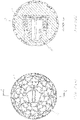
- Figure 2(a) shows a top view of the illuminable ball and Figure 2(b) show a cross-sectional view of the assembled components.
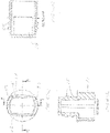
- Figures 3(a) and 3(b) show the hollow casing of the illuminable ball having three concentric cavities 10, 11, 12.
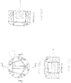
- the diametrically larger cavity 10 provides a flat base to captively hold a flat skirt 31 (shown in Figures 4(b) and 4(c) ) of the outer latch 3.
- the intermediate cavity 11 locates tubular housing 32 to which the skirt is attached and a top, open, end of the housing 32 having a lip 33 for captively securing the inner latch 4.
- the upper cavity 12 engages with and supports the combination of cap 4 and housing 3.
- Child resistant closures formed by two nested members or latches are known in the art.
- inner and outer latches are provided with cooperating sets of ratchet teeth which engage each other when the inner latch is rotated in a direction to close an opening (usually the clockwise direction).
- the ratchet teeth cam or ratchet past each other on inclined surfaces so that the latches cannot be removed by mere counter-clockwise rotation.
- the teeth of the latches are normally kept apart by a resilient springs 34, one single spring central to the section being shown in the exemplary embodiment, the spring being affixed to an internal cavity section surface of the skirt 31.
- ratchet teeth 36 Formed on the cavity space internal surface of the skirt 31, and circumferentially surrounding the spring 34, are a plurality of ratchet teeth 36 separated by a plurality of ramps 37.
- the outer surface of the tubular housing 32 is castellated for increased securement into mating castellations in the intermediate cavity 11.
- the inner latch is frusto-conically shaped and has an internal screw thread 41 arranged to mate with a corresponding external screw thread 51 on housing 5.
- a base 42 of latch 4 has a circumferential rebate 43 against the base of which act leaf springs 34.
- Formed in the base 42 are ramps 44 for abutting with the teeth 36 when the inner latch is turned in a first direction to rotate the inner latch in the outer latch so that the external screw thread 51 may engage with internal screw threads 41 to secure the housing into the inner latch.
- the base 42 also has ratchet teeth 45 to engage with the ratchet teeth 36 when downward pressure is applied on the inner latch to compress the leaf springs 34 so that the ratchet teeth engage and when the inner latch is rotated in a second, counter-clockwise, direction, so the combination of cap and housing may be unscrewed from the inner latch 4.
- An upper external periphery of the inner latch 4 has a lip 46 which is arranged to engage under lip 33 when the inner latch is forced into the cavity of outer latch 3.
- the housing 5 has a lower portion thereof formed by external screw threads 51 and the upper portion is formed by parallel sides 52 joined by opposing arcuate sides 53.
- the arcuate sides 53 are provided with a pair of external protrusions 54 and the sides 52 are provided with a pair of protrusions 55.
- the housing has an internal chamber 56 having a base upon which a printed circuit board (not shown) is mounted for the at least one light emitting diode (LED) and electrical circuitry associated therewith to be described hereinafter.
- LED light emitting diode
- the cap 6 has internal indentations 61, 62 for mating with the protrusions 54, 55 respectively.
- the cap is a force-fit over the housing 5, but may also be secured thereto by adhesive.
- the integrated circuit is triggered by an inertia switch 84 which is normally closed, but opens upon a predetermined G-force so that the integrated circuit 83 applies energy to a pair of parallel coupled LEDs 85, each having a load resistor 86. It is to be understood that fewer or more LEDs may be employed, as desired.
- the inertia switch 84 may be arranged to be open-circuited when the ball is thrown or when it strikes the ground and the integrated circuit 83 may be arranged to provide pulsating current to the LEDs to provide a flashing light or a constant light for a predetermined period of time before the inertia switch 84 closes.
- the cap, housing, inner and outer latches may be formed of plastics material.
- Embodiments of the present invention thus provide an illuminable ball with the power source and associated electrical circuitry secured by a low reverse torque closure assembly of a kind sometimes referred to as a two-piece child-resistant closure, whereby the combination of cap, housing and inner latch is freely rotatable until downward pressure is applied and an anticlockwise turning motion is applied to unscrew the housing from the latch so as to obtain access to replace the battery cells of the power source or other electrical components.
- embodiments of the invention provide an illuminable ball that has a translucent spherical hollow casing 1 in which is housed at least one light emitting diode (LED) 85, and electrical control circuitry 81 - 84 therefor which is arranged to activate the LED upon a predetermined G-force being exceeded.
- the casing has a cover 5, 6 which is attached to the casing by a low reverse torque closure assembly comprising inner and outer latches 4, 3, whereby the inner latch may be rotated in a removeable direction when insufficient force is applied to the inner latch so that it is prevented from engaging with the outer latch whereby undesired or accidental removal of the housing screwed into the inner latch is prevented.
Landscapes
- Health & Medical Sciences (AREA)
- General Health & Medical Sciences (AREA)
- Physical Education & Sports Medicine (AREA)
- Life Sciences & Earth Sciences (AREA)
- General Engineering & Computer Science (AREA)
- Engineering & Computer Science (AREA)
- Environmental Sciences (AREA)
- Animal Behavior & Ethology (AREA)
- Zoology (AREA)
- Animal Husbandry (AREA)
- Biodiversity & Conservation Biology (AREA)
- Dentistry (AREA)
- Casings For Electric Apparatus (AREA)
- Management, Administration, Business Operations System, And Electronic Commerce (AREA)
- Illuminated Signs And Luminous Advertising (AREA)
Abstract
Description
- This invention relates to an illuminable ball, particularly, although not exclusively, to a ball that is intended for the pet market, especially for dogs. It is well known that dogs enjoy chasing and fetching balls and by arranging a ball to be illuminated, the likelihood of it being lost, especially at night, is reduced.
- Known illuminated balls tend to be of three main types:
- 1. A phosphorescent ball, but these have the disadvantage that they tend to quickly fade and light from them cannot be guaranteed.
- 2. Balls where power source batteries are sealed into the ball and cannot be changed, which represents a significant waste when the batteries die, and
- 3. A structure in which the ball is in two semi-spherical halves and screwed together by mating screw threads on each half, but this has the disadvantage that the parts tend to become unscrewed, resulting in the batteries and electrical components providing energy to light emitting diodes (LEDs) becoming exposed and becoming and rendering a severe danger to animals or that are liable to chew and swallow them.
- The present invention seeks to provide an exercise ball for pets which is illuminable and in which the foregoing problems are substantially mitigated.
- According to this invention there is provided an illuminable ball including a translucent spherical hollow casing in which is housed illumination means comprising at least one LED and control means arranged to illuminate said at least one LED; and cover means providing access to the illumination means inside said hollow casing; wherein said cover means is attached to said casing by a child-resistant closure or low reverse torque closure assembly.
- Preferably, the low reverse torque closure assembly comprises a closure requiring the simultaneous application of a linear force along an axis together with a rotation about said axis in a removal direction to remove the cover from the hollow casing. More preferably the linear force is a downward force (directed towards the ball) and the removal direction is the counter-clockwise direction.
- Child-resistant closures are closures that discourage unauthorised opening by requiring the combination of simultaneous actions - usually pressing downwards or lifting upwards combined with a rotation. The downward or upward linear force brings nested inner and outer members into engagement so that rotation in a removal direction (usually the counter-clockwise direction) removes the cover.
- Child resistant closures can also be described as low or negligible reverse torque closures since they comprise a ratcheting assembly that provides negligible reverse torque during undepressed counter-clockwise rotation of the outer member. The torque caused by frictional contact of outer and inner members when the undepressed closure is turned in the counter-clockwise direction being low or negligible in the sense that it is insufficient to cause removal of the cover from the closure.
- Preferably the low reverse torque closure assembly includes an inner latch formed by an internally screw threaded cylindrical first member which is concentrically retained to be captive within an outer latch formed by a cylindrical second member having a base upon which are formed first ratchet teeth abutting with spring which is embedded into the centre of the base (as shown in
figure 4 (a) ) which means on a facing wall of the first member when the inner latch is turned in a first direction to rotate the inner latch into the outer latch, causing the internal screw threads on the cylindrical first member to cooperate with mating threads on the cover means to securely close said hollow casing; and the central spring pushing an upwards force up and over the ramp means with negligible back ratchet torque when the inner latch is turned in a second direction opposite to said first direction without the application of a downforce by virtue of the central spring member disposed in the base of the second member so as to form a space between the first and second members until a downward force against the at least one spring member is applied on the inner latch and a torque simultaneously applied on the inner latch cause the first ratchet teeth to engage with second ratchet teeth on the first member and the inner latch is rotated in a second direction to remove said cover means. - Advantageously, said ramp means define a low friction surface during undepressed counter-clockwise rotation of the cover means and a contact area during clockwise rotation of the cover means.
- Conveniently, the second ratchet teeth define a contact area for removal of the cover means from the hollow casing when the cover means is depressed.
- Preferably, a slot is provided in an outer surface of said cover means for insertion of a removal implement arranged to provide said downward force and a twisting torque.
- Conveniently, said cover means comprises a cap in which said slot is located and said cap is matingly secured to a housing within which is mounted said control means, said housing having an external screw thread arranged to mate with the internal screw thread of the cylindrical first member.
- Advantageously, said control means includes an inertial switch which is normally closed, but which is arranged to open upon activation by a predetermined G-force to permit a power source to energise said at least one LED.
- Preferably, said power source is at least one battery cell which is accessed by rotating the cover means in said second direction and applying a downward force to lock the inner and outer latches together so that a combination of cap and housing may be unscrewed from the inner latch, whereas without the application of a downward force, the inner latch rotatably slides over the outer latch.
- The invention will now be described, by way of example, with reference to the accompanying drawings, in which:
-
Figure 1 shows an exploded perspective view of an illuminable ball in accordance with this invention, -
Figure 2(a) shows a top view of the illuminable ball ofFigure 1 , -
Figure 2(b) shows a cross-sectional view along double arrow-headed lines A-A ofFigure 2(a) , showing the assembled parts of the illuminable ball in situ, -
Figure 3(a) shows the illuminable ball casing with the cover removed, -
Figure 3(b) shows a cross-section along double arrow-headed lines B-B ofFigure 3(a) , -
Figure 4(a) shows a top view of an outer latch used in the illuminable ball, -
Figure 4(b) shows a cross-section along double arrow-headed lines I-I ofFigure 4(a) , -
Figure 4(c) shows a cross-sectional view along double arrow-headed lines J-J ofFigure 4(a) , -
Figure 5(a) shows a top view of an inner latch that is retained within the outer latch, -
Figure 5(b) shows a cross-section along double arrow-headed lines G-G ofFigure 5(a) , -
Figure 5(c) shows a cross-sectional view along double arrow-headed lines ofFigure 5(a) , -
Figure 6(a) shows a top view of a housing for power source and control circuitry for the LEDs, -
Figure 6(b) shows a cross-section along double arrow-headed lines E-E ofFigure 6(a) , -
Figure 6(c) shows a cross-sectional view along double arrow-headed lines F-F ofFigure 6(a) , -
Figure 7(a) shows a top view of a cover that is secured to the housing, -
Figure 7(b) shows a cross-section along double arrow-headed lines C-C ofFigure 7(a) , -
Figure 7(c) shows a cross-section along double arrow-headed lines D-D ofFigure 7(a) , and -
Figure 8 shows a circuit diagram of the electrical components used in the illuminable ball of this invention. - In the Figures like reference numerals denote like parts.
- Referring to
Figure 1 , the illuminable ball has a translucent spherical hollow housing 1 made from, for example, silicone or thermoplastic rubber (TPR) having a textured and patterned outer surface. The housing has an opening through and in which is located the series connection of anouter latch 3, aninner latch 4 which is retained within theouter latch 3, ahousing 5 and acap 6. Theinner latch 3 has an internal screw thread which mates with an external screw thread on thehousing 5 which is arranged to mount a power source and electrical circuitry for illuminating at least one LED. Thecap 6 is arranged to be a push fit and is secured over an end of the housing remote from the external screw thread. The cap has a partially diametrically extendingslot 7 for insertion of a removal implement such as a screwdriver, or coin, to screw the combination of cap and housing into and out of theinner latch 4. -
Figure 2(a) shows a top view of the illuminable ball andFigure 2(b) show a cross-sectional view of the assembled components. -
Figures 3(a) and 3(b) show the hollow casing of the illuminable ball having three concentric cavities 10, 11, 12. The diametrically larger cavity 10 provides a flat base to captively hold a flat skirt 31 (shown inFigures 4(b) and 4(c) ) of theouter latch 3. The intermediate cavity 11 locatestubular housing 32 to which the skirt is attached and a top, open, end of thehousing 32 having alip 33 for captively securing theinner latch 4. The upper cavity 12 engages with and supports the combination ofcap 4 andhousing 3. - Child resistant closures formed by two nested members or latches are known in the art. Typically, inner and outer latches are provided with cooperating sets of ratchet teeth which engage each other when the inner latch is rotated in a direction to close an opening (usually the clockwise direction). When the inner latch is rotated in a removal direction (usually counter-clockwise), the ratchet teeth cam or ratchet past each other on inclined surfaces so that the latches cannot be removed by mere counter-clockwise rotation. The teeth of the latches are normally kept apart by a
resilient springs 34, one single spring central to the section being shown in the exemplary embodiment, the spring being affixed to an internal cavity section surface of theskirt 31. - Formed on the cavity space internal surface of the
skirt 31, and circumferentially surrounding thespring 34, are a plurality ofratchet teeth 36 separated by a plurality oframps 37. - The outer surface of the
tubular housing 32 is castellated for increased securement into mating castellations in the intermediate cavity 11. - The inner latch, particularly shown in
Figures 5(a) to 5(c) , is frusto-conically shaped and has aninternal screw thread 41 arranged to mate with a corresponding external screw thread 51 onhousing 5. A base 42 oflatch 4 has a circumferential rebate 43 against the base of which act leaf springs 34. Formed in the base 42 areramps 44 for abutting with theteeth 36 when the inner latch is turned in a first direction to rotate the inner latch in the outer latch so that the external screw thread 51 may engage withinternal screw threads 41 to secure the housing into the inner latch. The base 42 also has ratchetteeth 45 to engage with theratchet teeth 36 when downward pressure is applied on the inner latch to compress theleaf springs 34 so that the ratchet teeth engage and when the inner latch is rotated in a second, counter-clockwise, direction, so the combination of cap and housing may be unscrewed from theinner latch 4. - An upper external periphery of the
inner latch 4 has alip 46 which is arranged to engage underlip 33 when the inner latch is forced into the cavity ofouter latch 3. - The housing for the LEDs and electrical control apparatus will now be described with reference to
Figures 6(a) and 6(b) . - The
housing 5 has a lower portion thereof formed by external screw threads 51 and the upper portion is formed byparallel sides 52 joined by opposing arcuate sides 53. The arcuate sides 53 are provided with a pair of external protrusions 54 and thesides 52 are provided with a pair ofprotrusions 55. The housing has aninternal chamber 56 having a base upon which a printed circuit board (not shown) is mounted for the at least one light emitting diode (LED) and electrical circuitry associated therewith to be described hereinafter. - The
cap 6 hasinternal indentations 61, 62 for mating with theprotrusions 54, 55 respectively. The cap is a force-fit over thehousing 5, but may also be secured thereto by adhesive. - The electrical circuitry for the illuminable ball will now be described with reference to
Figure 8 . - A
power source 81 formed, for example, by a pair of serially connected 3-Volt battery cells, such as CR2032 cells, is smoothed by acapacitor 82 and applied to anintegrated circuit 83. The integrated circuit is triggered by an inertia switch 84 which is normally closed, but opens upon a predetermined G-force so that theintegrated circuit 83 applies energy to a pair of parallel coupledLEDs 85, each having aload resistor 86. It is to be understood that fewer or more LEDs may be employed, as desired. The inertia switch 84 may be arranged to be open-circuited when the ball is thrown or when it strikes the ground and theintegrated circuit 83 may be arranged to provide pulsating current to the LEDs to provide a flashing light or a constant light for a predetermined period of time before the inertia switch 84 closes. - The cap, housing, inner and outer latches may be formed of plastics material.
- Embodiments of the present invention thus provide an illuminable ball with the power source and associated electrical circuitry secured by a low reverse torque closure assembly of a kind sometimes referred to as a two-piece child-resistant closure, whereby the combination of cap, housing and inner latch is freely rotatable until downward pressure is applied and an anticlockwise turning motion is applied to unscrew the housing from the latch so as to obtain access to replace the battery cells of the power source or other electrical components.
- In summary, embodiments of the invention provide an illuminable ball that has a translucent spherical hollow casing 1 in which is housed at least one light emitting diode (LED) 85, and electrical control circuitry 81 - 84 therefor which is arranged to activate the LED upon a predetermined G-force being exceeded. The casing has a
cover outer latches
Claims (9)
- An illuminable ball including a translucent spherical hollow casing in which is housed illumination means comprising at least one LED and control means arranged to illuminate said at least one LED; and cover means providing access to the illumination means inside said hollow casing; wherein said cover means is attached to said casing by a low reverse torque closure.
- The illuminable ball of claim 1 wherein the low reverse torque closure comprises a closure requiring the simultaneous application of a linear force along an axis together with a rotation around said axis in a removal direction to remove the cover means from the hollow casing.
- An illuminable ball as claimed in claim 1 or claim 2, wherein the low reverse torque closure includes an inner latch formed by an internally screw threaded cylindrical first member which is concentrically retained to be captive within an outer latch formed by a cylindrical second member having a base upon which are formed first ratchet teeth abutting with ramp means on a facing wall of the first member when the inner latch is turned in a first direction to rotate the inner latch into the outer latch, causing the internal screw threads on the cylindrical first member to cooperate with mating threads on the cover means to securely close said hollow casing; and the first ratchet teeth sliding up and over the ramp means with negligible back ratchet torque when the inner latch is turned in a second direction opposite to said first direction without the application of a downforce by virtue of at least one resilient spring member disposed in the base of the second member so as to form a space between the first and second members until a downward force against the at least one spring member is applied on the inner latch and a torque simultaneously applied on the inner latch causes the first ratchet teeth to engage with second ratchet teeth on the first member and the inner latch is rotated in a second direction to remove said cover means.
- An illuminable ball as claimed in claim 3, wherein said ramp means define a low friction surface during undepressed counter-clockwise rotation of the cover means and a contact area during clockwise rotation of the cover means.
- An illuminable ball as claimed in claim 3 or 4, wherein the second ratchet teeth define a contact area for removal of the cover means from the hollow casing when the cover means is depressed.
- An illuminable ball as claimed in any preceding claim, wherein a slot is provided in an outer surface of said cover means for insertion of a removal implement arranged to provide a downward force and a twisting torque to remove the cover means from the hollow casing.
- An illuminable ball as claimed in claim 6, wherein said cover means comprises a cap in which said slot is located and said cap is matingly secured to a housing within which is mounted said control means, said housing having an external screw thread arranged to mate with the internal screw thread of the cylindrical first member.
- An illuminable ball as claimed in any preceding claim, wherein said control means includes an inertial switch which is normally closed, but which is arranged to open upon activation by a predetermined G-force to permit a power source to energise said at least one LED.
- An illuminable ball as claimed in claim 8, wherein said power source is at least one battery cell which is accessed by rotating the cover means in said second direction and applying a downward force to lock the inner and outer latches together so that a combination of cap and housing may be unscrewed from the inner latch, whereas without the application of a downward force, the inner latch rotatably slides over the outer latch.
Priority Applications (1)
| Application Number | Priority Date | Filing Date | Title |
|---|---|---|---|
| US17/709,328 US12029946B2 (en) | 2021-03-30 | 2022-03-30 | Illuminable device with low reverse torque closure |
Applications Claiming Priority (1)
| Application Number | Priority Date | Filing Date | Title |
|---|---|---|---|
| GB2104491.2A GB2605765A (en) | 2021-04-13 | 2021-04-13 | Ultra illuminatable lightning ball |
Publications (3)
| Publication Number | Publication Date |
|---|---|
| EP4074173A1 true EP4074173A1 (en) | 2022-10-19 |
| EP4074173B1 EP4074173B1 (en) | 2023-10-04 |
| EP4074173C0 EP4074173C0 (en) | 2023-10-04 |
Family
ID=75783776
Family Applications (1)
| Application Number | Title | Priority Date | Filing Date |
|---|---|---|---|
| EP21213276.5A Active EP4074173B1 (en) | 2021-03-30 | 2021-12-08 | Illuminable ball |
Country Status (3)
| Country | Link |
|---|---|
| US (1) | US12029946B2 (en) |
| EP (1) | EP4074173B1 (en) |
| GB (1) | GB2605765A (en) |
Families Citing this family (5)
| Publication number | Priority date | Publication date | Assignee | Title |
|---|---|---|---|---|
| US12317862B2 (en) * | 2018-02-26 | 2025-06-03 | Vasiliki Karras | Pet treat holder and safety device |
| US20240147964A1 (en) * | 2022-11-04 | 2024-05-09 | P&P Imports LLC | Apparatus for a pet treat holder |
| US12256714B2 (en) * | 2023-02-08 | 2025-03-25 | T.F.H. Publications, Inc. | Separable chew toy having an internal cavity accessible via a clutch mechanism |
| USD1077098S1 (en) * | 2025-01-09 | 2025-05-27 | Yufan Hou | Luminous hockey ball |
| US12527300B1 (en) * | 2025-04-07 | 2026-01-20 | Patrick Anderson | Durable pet toy with scent-retention capability |
Citations (2)
| Publication number | Priority date | Publication date | Assignee | Title |
|---|---|---|---|---|
| US6117030A (en) * | 1998-06-24 | 2000-09-12 | Green, Sr.; Ronald J. | Illuminated game ball and method of play |
| US20170188546A1 (en) * | 2016-01-05 | 2017-07-06 | Nite Ize, Inc. | Systems and methods for a light-up object with enhanced features for animals |
Family Cites Families (8)
| Publication number | Priority date | Publication date | Assignee | Title |
|---|---|---|---|---|
| US4893224A (en) * | 1988-12-20 | 1990-01-09 | Cooper Industries | Emergency lighting fixture |
| GB2242364B (en) * | 1990-03-28 | 1994-03-23 | Colin Dowden | Unit and article providing an optical effect |
| US5280842A (en) * | 1992-12-15 | 1994-01-25 | Kerr Group, Inc. | Low reverse torque closure assembly |
| US5609262A (en) * | 1995-09-22 | 1997-03-11 | Rieke Corporation | Tamper evident, child-resistant closure |
| US8292454B2 (en) * | 2004-11-12 | 2012-10-23 | Chemical Light, Inc. | Externally switchable illuminated balloon inflator |
| US7179181B2 (en) * | 2005-07-19 | 2007-02-20 | Li-Lin Ko | Illuminating ball |
| CN204083826U (en) * | 2014-07-11 | 2015-01-07 | 北京文海阳工贸有限责任公司 | A kind of luminescent ball |
| US11272690B2 (en) * | 2016-09-15 | 2022-03-15 | II Anthony Gelardi | Toy with mechanically locked inner capsule |
-
2021
- 2021-04-13 GB GB2104491.2A patent/GB2605765A/en not_active Withdrawn
- 2021-12-08 EP EP21213276.5A patent/EP4074173B1/en active Active
-
2022
- 2022-03-30 US US17/709,328 patent/US12029946B2/en active Active
Patent Citations (2)
| Publication number | Priority date | Publication date | Assignee | Title |
|---|---|---|---|---|
| US6117030A (en) * | 1998-06-24 | 2000-09-12 | Green, Sr.; Ronald J. | Illuminated game ball and method of play |
| US20170188546A1 (en) * | 2016-01-05 | 2017-07-06 | Nite Ize, Inc. | Systems and methods for a light-up object with enhanced features for animals |
Non-Patent Citations (2)
| Title |
|---|
| ANONYMOUS: "Lightening LED Pet Ball - Pet Safe Dog Ball (Canceled) by Mark Cleghorn - Kickstarter", 19 September 2021 (2021-09-19), pages 1 - 7, XP055916909, Retrieved from the Internet <URL:https://www.kickstarter.com/projects/wafflesthedachshund/lightening-led-pet-ball-pet-safe-dog-ball/description> [retrieved on 20220502] * |
| ANONYMOUS: "Lightening LED Pet Ball - Pet Safe Dog Ball (Canceled) by Mark Cleghorn - Kickstarter", 19 September 2021 (2021-09-19), XP055917327, Retrieved from the Internet <URL:https://www.kickstarter.com/projects/wafflesthedachshund/lightening-led-pet-ball-pet-safe-dog-ball/description> [retrieved on 20220503] * |
Also Published As
| Publication number | Publication date |
|---|---|
| EP4074173B1 (en) | 2023-10-04 |
| GB202104491D0 (en) | 2021-05-12 |
| EP4074173C0 (en) | 2023-10-04 |
| US20220323830A1 (en) | 2022-10-13 |
| GB2605765A (en) | 2022-10-19 |
| US12029946B2 (en) | 2024-07-09 |
Similar Documents
| Publication | Publication Date | Title |
|---|---|---|
| EP4074173B1 (en) | Illuminable ball | |
| US20230292731A1 (en) | Portable mosquito killing lamp | |
| ATE80851T1 (en) | CONTAINER AND CAP WITH OR WITHOUT CHILD RESISTANT. | |
| JP7584636B2 (en) | Flashlight Assembly | |
| US6971762B2 (en) | Dual mode switch mechanism for flashlights | |
| CA2111453A1 (en) | Low reverse torque closure assembly | |
| CA2435708A1 (en) | Bar-shaped lamp | |
| US20190350172A1 (en) | Electronic retractable pet leash device | |
| GB2602827A (en) | Illuminatable ball | |
| US20080266837A1 (en) | Flashlight | |
| US7229182B2 (en) | Lighted hoop | |
| US20100269870A1 (en) | Umbrella with an illumination device | |
| US5738011A (en) | Amusement stamp | |
| US6682212B2 (en) | Light-emitting pen with a light-emitting body at a middle section of a pen tube | |
| ITMI20010276A1 (en) | LIGHTING DEVICE PARTICULARLY DESIGNED TO BE APPLIED TO FOOTWEAR | |
| US12146651B1 (en) | Luminous object combination device and combination method | |
| US4399496A (en) | Battery powered lamp device | |
| US7229187B2 (en) | Compact illumination source with novel actuator | |
| DE202011052228U1 (en) | Battery operated lighting device with holder | |
| DE202019102940U1 (en) | Electronic clothing accessory | |
| CN205476887U (en) | Locking device with illuminated indicator | |
| KR200327524Y1 (en) | Compact case having light in hinge | |
| US5762534A (en) | Automatic opening/closing mechanism | |
| JP2025181133A (en) | Lighting equipment | |
| JP3042497U (en) | Fishing light |
Legal Events
| Date | Code | Title | Description |
|---|---|---|---|
| PUAI | Public reference made under article 153(3) epc to a published international application that has entered the european phase |
Free format text: ORIGINAL CODE: 0009012 |
|
| STAA | Information on the status of an ep patent application or granted ep patent |
Free format text: STATUS: THE APPLICATION HAS BEEN PUBLISHED |
|
| AK | Designated contracting states |
Kind code of ref document: A1 Designated state(s): AL AT BE BG CH CY CZ DE DK EE ES FI FR GB GR HR HU IE IS IT LI LT LU LV MC MK MT NL NO PL PT RO RS SE SI SK SM TR |
|
| STAA | Information on the status of an ep patent application or granted ep patent |
Free format text: STATUS: REQUEST FOR EXAMINATION WAS MADE |
|
| GRAP | Despatch of communication of intention to grant a patent |
Free format text: ORIGINAL CODE: EPIDOSNIGR1 |
|
| STAA | Information on the status of an ep patent application or granted ep patent |
Free format text: STATUS: GRANT OF PATENT IS INTENDED |
|
| 17P | Request for examination filed |
Effective date: 20230323 |
|
| RBV | Designated contracting states (corrected) |
Designated state(s): AL AT BE BG CH CY CZ DE DK EE ES FI FR GB GR HR HU IE IS IT LI LT LU LV MC MK MT NL NO PL PT RO RS SE SI SK SM TR |
|
| RIC1 | Information provided on ipc code assigned before grant |
Ipc: A63B 43/06 20060101ALI20230412BHEP Ipc: A63B 39/00 20060101ALI20230412BHEP Ipc: A01K 15/02 20060101AFI20230412BHEP |
|
| INTG | Intention to grant announced |
Effective date: 20230502 |
|
| GRAS | Grant fee paid |
Free format text: ORIGINAL CODE: EPIDOSNIGR3 |
|
| GRAA | (expected) grant |
Free format text: ORIGINAL CODE: 0009210 |
|
| STAA | Information on the status of an ep patent application or granted ep patent |
Free format text: STATUS: THE PATENT HAS BEEN GRANTED |
|
| AK | Designated contracting states |
Kind code of ref document: B1 Designated state(s): AL AT BE BG CH CY CZ DE DK EE ES FI FR GB GR HR HU IE IS IT LI LT LU LV MC MK MT NL NO PL PT RO RS SE SI SK SM TR |
|
| REG | Reference to a national code |
Ref country code: GB Ref legal event code: FG4D |
|
| REG | Reference to a national code |
Ref country code: CH Ref legal event code: EP |
|
| REG | Reference to a national code |
Ref country code: IE Ref legal event code: FG4D |
|
| REG | Reference to a national code |
Ref country code: DE Ref legal event code: R096 Ref document number: 602021005626 Country of ref document: DE |
|
| U01 | Request for unitary effect filed |
Effective date: 20231006 |
|
| U07 | Unitary effect registered |
Designated state(s): AT BE BG DE DK EE FI FR IT LT LU LV MT NL PT SE SI Effective date: 20231018 |
|
| U20 | Renewal fee for the european patent with unitary effect paid |
Year of fee payment: 3 Effective date: 20231201 |
|
| PG25 | Lapsed in a contracting state [announced via postgrant information from national office to epo] |
Ref country code: GR Free format text: LAPSE BECAUSE OF FAILURE TO SUBMIT A TRANSLATION OF THE DESCRIPTION OR TO PAY THE FEE WITHIN THE PRESCRIBED TIME-LIMIT Effective date: 20240105 |
|
| PG25 | Lapsed in a contracting state [announced via postgrant information from national office to epo] |
Ref country code: IS Free format text: LAPSE BECAUSE OF FAILURE TO SUBMIT A TRANSLATION OF THE DESCRIPTION OR TO PAY THE FEE WITHIN THE PRESCRIBED TIME-LIMIT Effective date: 20240204 |
|
| PG25 | Lapsed in a contracting state [announced via postgrant information from national office to epo] |
Ref country code: ES Free format text: LAPSE BECAUSE OF FAILURE TO SUBMIT A TRANSLATION OF THE DESCRIPTION OR TO PAY THE FEE WITHIN THE PRESCRIBED TIME-LIMIT Effective date: 20231004 |
|
| PG25 | Lapsed in a contracting state [announced via postgrant information from national office to epo] |
Ref country code: IS Free format text: LAPSE BECAUSE OF FAILURE TO SUBMIT A TRANSLATION OF THE DESCRIPTION OR TO PAY THE FEE WITHIN THE PRESCRIBED TIME-LIMIT Effective date: 20240204 Ref country code: GR Free format text: LAPSE BECAUSE OF FAILURE TO SUBMIT A TRANSLATION OF THE DESCRIPTION OR TO PAY THE FEE WITHIN THE PRESCRIBED TIME-LIMIT Effective date: 20240105 Ref country code: ES Free format text: LAPSE BECAUSE OF FAILURE TO SUBMIT A TRANSLATION OF THE DESCRIPTION OR TO PAY THE FEE WITHIN THE PRESCRIBED TIME-LIMIT Effective date: 20231004 |
|
| PG25 | Lapsed in a contracting state [announced via postgrant information from national office to epo] |
Ref country code: RS Free format text: LAPSE BECAUSE OF FAILURE TO SUBMIT A TRANSLATION OF THE DESCRIPTION OR TO PAY THE FEE WITHIN THE PRESCRIBED TIME-LIMIT Effective date: 20231004 Ref country code: PL Free format text: LAPSE BECAUSE OF FAILURE TO SUBMIT A TRANSLATION OF THE DESCRIPTION OR TO PAY THE FEE WITHIN THE PRESCRIBED TIME-LIMIT Effective date: 20231004 Ref country code: NO Free format text: LAPSE BECAUSE OF FAILURE TO SUBMIT A TRANSLATION OF THE DESCRIPTION OR TO PAY THE FEE WITHIN THE PRESCRIBED TIME-LIMIT Effective date: 20240104 Ref country code: HR Free format text: LAPSE BECAUSE OF FAILURE TO SUBMIT A TRANSLATION OF THE DESCRIPTION OR TO PAY THE FEE WITHIN THE PRESCRIBED TIME-LIMIT Effective date: 20231004 |
|
| REG | Reference to a national code |
Ref country code: DE Ref legal event code: R097 Ref document number: 602021005626 Country of ref document: DE |
|
| PG25 | Lapsed in a contracting state [announced via postgrant information from national office to epo] |
Ref country code: CZ Free format text: LAPSE BECAUSE OF FAILURE TO SUBMIT A TRANSLATION OF THE DESCRIPTION OR TO PAY THE FEE WITHIN THE PRESCRIBED TIME-LIMIT Effective date: 20231004 |
|
| PG25 | Lapsed in a contracting state [announced via postgrant information from national office to epo] |
Ref country code: SK Free format text: LAPSE BECAUSE OF FAILURE TO SUBMIT A TRANSLATION OF THE DESCRIPTION OR TO PAY THE FEE WITHIN THE PRESCRIBED TIME-LIMIT Effective date: 20231004 |
|
| PG25 | Lapsed in a contracting state [announced via postgrant information from national office to epo] |
Ref country code: SM Free format text: LAPSE BECAUSE OF FAILURE TO SUBMIT A TRANSLATION OF THE DESCRIPTION OR TO PAY THE FEE WITHIN THE PRESCRIBED TIME-LIMIT Effective date: 20231004 Ref country code: SK Free format text: LAPSE BECAUSE OF FAILURE TO SUBMIT A TRANSLATION OF THE DESCRIPTION OR TO PAY THE FEE WITHIN THE PRESCRIBED TIME-LIMIT Effective date: 20231004 Ref country code: RO Free format text: LAPSE BECAUSE OF FAILURE TO SUBMIT A TRANSLATION OF THE DESCRIPTION OR TO PAY THE FEE WITHIN THE PRESCRIBED TIME-LIMIT Effective date: 20231004 Ref country code: CZ Free format text: LAPSE BECAUSE OF FAILURE TO SUBMIT A TRANSLATION OF THE DESCRIPTION OR TO PAY THE FEE WITHIN THE PRESCRIBED TIME-LIMIT Effective date: 20231004 |
|
| PLBE | No opposition filed within time limit |
Free format text: ORIGINAL CODE: 0009261 |
|
| STAA | Information on the status of an ep patent application or granted ep patent |
Free format text: STATUS: NO OPPOSITION FILED WITHIN TIME LIMIT |
|
| PG25 | Lapsed in a contracting state [announced via postgrant information from national office to epo] |
Ref country code: MC Free format text: LAPSE BECAUSE OF FAILURE TO SUBMIT A TRANSLATION OF THE DESCRIPTION OR TO PAY THE FEE WITHIN THE PRESCRIBED TIME-LIMIT Effective date: 20231004 |
|
| PG25 | Lapsed in a contracting state [announced via postgrant information from national office to epo] |
Ref country code: MC Free format text: LAPSE BECAUSE OF FAILURE TO SUBMIT A TRANSLATION OF THE DESCRIPTION OR TO PAY THE FEE WITHIN THE PRESCRIBED TIME-LIMIT Effective date: 20231004 |
|
| 26N | No opposition filed |
Effective date: 20240705 |
|
| REG | Reference to a national code |
Ref country code: IE Ref legal event code: MM4A |
|
| PG25 | Lapsed in a contracting state [announced via postgrant information from national office to epo] |
Ref country code: IE Free format text: LAPSE BECAUSE OF NON-PAYMENT OF DUE FEES Effective date: 20231208 |
|
| PG25 | Lapsed in a contracting state [announced via postgrant information from national office to epo] |
Ref country code: IE Free format text: LAPSE BECAUSE OF NON-PAYMENT OF DUE FEES Effective date: 20231208 |
|
| U20 | Renewal fee for the european patent with unitary effect paid |
Year of fee payment: 4 Effective date: 20241230 |
|
| PG25 | Lapsed in a contracting state [announced via postgrant information from national office to epo] |
Ref country code: CY Free format text: LAPSE BECAUSE OF FAILURE TO SUBMIT A TRANSLATION OF THE DESCRIPTION OR TO PAY THE FEE WITHIN THE PRESCRIBED TIME-LIMIT; INVALID AB INITIO Effective date: 20211208 |
|
| REG | Reference to a national code |
Ref country code: CH Ref legal event code: PL |
|
| PG25 | Lapsed in a contracting state [announced via postgrant information from national office to epo] |
Ref country code: CH Free format text: LAPSE BECAUSE OF NON-PAYMENT OF DUE FEES Effective date: 20241231 |
|
| PG25 | Lapsed in a contracting state [announced via postgrant information from national office to epo] |
Ref country code: TR Free format text: LAPSE BECAUSE OF FAILURE TO SUBMIT A TRANSLATION OF THE DESCRIPTION OR TO PAY THE FEE WITHIN THE PRESCRIBED TIME-LIMIT Effective date: 20231004 |
|
| U20 | Renewal fee for the european patent with unitary effect paid |
Year of fee payment: 5 Effective date: 20251110 |
|
| PGFP | Annual fee paid to national office [announced via postgrant information from national office to epo] |
Ref country code: GB Payment date: 20260120 Year of fee payment: 5 |
|
| PG25 | Lapsed in a contracting state [announced via postgrant information from national office to epo] |
Ref country code: HU Free format text: LAPSE BECAUSE OF FAILURE TO SUBMIT A TRANSLATION OF THE DESCRIPTION OR TO PAY THE FEE WITHIN THE PRESCRIBED TIME-LIMIT; INVALID AB INITIO Effective date: 20211208 |
|
| PG25 | Lapsed in a contracting state [announced via postgrant information from national office to epo] |
Ref country code: CH Free format text: THE PATENT HAS BEEN ANNULLED BY A DECISION OF A NATIONAL AUTHORITY Effective date: 20241231 |