EP4072662B1 - Medical device with cam based rotating fastener - Google Patents
Medical device with cam based rotating fastener Download PDFInfo
- Publication number
- EP4072662B1 EP4072662B1 EP20838763.9A EP20838763A EP4072662B1 EP 4072662 B1 EP4072662 B1 EP 4072662B1 EP 20838763 A EP20838763 A EP 20838763A EP 4072662 B1 EP4072662 B1 EP 4072662B1
- Authority
- EP
- European Patent Office
- Prior art keywords
- rotatable member
- cam lobe
- slider
- channel
- lead
- Prior art date
- Legal status (The legal status is an assumption and is not a legal conclusion. Google has not performed a legal analysis and makes no representation as to the accuracy of the status listed.)
- Active
Links
Images








Classifications
-
- A—HUMAN NECESSITIES
- A61—MEDICAL OR VETERINARY SCIENCE; HYGIENE
- A61N—ELECTROTHERAPY; MAGNETOTHERAPY; RADIATION THERAPY; ULTRASOUND THERAPY
- A61N1/00—Electrotherapy; Circuits therefor
- A61N1/18—Applying electric currents by contact electrodes
- A61N1/32—Applying electric currents by contact electrodes alternating or intermittent currents
- A61N1/36—Applying electric currents by contact electrodes alternating or intermittent currents for stimulation
- A61N1/372—Arrangements in connection with the implantation of stimulators
- A61N1/375—Constructional arrangements, e.g. casings
- A61N1/3752—Details of casing-lead connections
-
- A—HUMAN NECESSITIES
- A61—MEDICAL OR VETERINARY SCIENCE; HYGIENE
- A61N—ELECTROTHERAPY; MAGNETOTHERAPY; RADIATION THERAPY; ULTRASOUND THERAPY
- A61N1/00—Electrotherapy; Circuits therefor
- A61N1/18—Applying electric currents by contact electrodes
- A61N1/32—Applying electric currents by contact electrodes alternating or intermittent currents
- A61N1/36—Applying electric currents by contact electrodes alternating or intermittent currents for stimulation
- A61N1/372—Arrangements in connection with the implantation of stimulators
- A61N1/375—Constructional arrangements, e.g. casings
- A61N1/3752—Details of casing-lead connections
- A61N1/3754—Feedthroughs
-
- A—HUMAN NECESSITIES
- A61—MEDICAL OR VETERINARY SCIENCE; HYGIENE
- A61N—ELECTROTHERAPY; MAGNETOTHERAPY; RADIATION THERAPY; ULTRASOUND THERAPY
- A61N1/00—Electrotherapy; Circuits therefor
- A61N1/18—Applying electric currents by contact electrodes
- A61N1/32—Applying electric currents by contact electrodes alternating or intermittent currents
- A61N1/36—Applying electric currents by contact electrodes alternating or intermittent currents for stimulation
- A61N1/3605—Implantable neurostimulators for stimulating central or peripheral nerve system
-
- A—HUMAN NECESSITIES
- A61—MEDICAL OR VETERINARY SCIENCE; HYGIENE
- A61N—ELECTROTHERAPY; MAGNETOTHERAPY; RADIATION THERAPY; ULTRASOUND THERAPY
- A61N1/00—Electrotherapy; Circuits therefor
- A61N1/18—Applying electric currents by contact electrodes
- A61N1/32—Applying electric currents by contact electrodes alternating or intermittent currents
- A61N1/36—Applying electric currents by contact electrodes alternating or intermittent currents for stimulation
- A61N1/3605—Implantable neurostimulators for stimulating central or peripheral nerve system
- A61N1/3606—Implantable neurostimulators for stimulating central or peripheral nerve system adapted for a particular treatment
- A61N1/36062—Spinal stimulation
-
- A—HUMAN NECESSITIES
- A61—MEDICAL OR VETERINARY SCIENCE; HYGIENE
- A61N—ELECTROTHERAPY; MAGNETOTHERAPY; RADIATION THERAPY; ULTRASOUND THERAPY
- A61N1/00—Electrotherapy; Circuits therefor
- A61N1/18—Applying electric currents by contact electrodes
- A61N1/32—Applying electric currents by contact electrodes alternating or intermittent currents
- A61N1/36—Applying electric currents by contact electrodes alternating or intermittent currents for stimulation
- A61N1/372—Arrangements in connection with the implantation of stimulators
- A61N1/37211—Means for communicating with stimulators
- A61N1/37235—Aspects of the external programmer
-
- A—HUMAN NECESSITIES
- A61—MEDICAL OR VETERINARY SCIENCE; HYGIENE
- A61N—ELECTROTHERAPY; MAGNETOTHERAPY; RADIATION THERAPY; ULTRASOUND THERAPY
- A61N1/00—Electrotherapy; Circuits therefor
- A61N1/18—Applying electric currents by contact electrodes
- A61N1/32—Applying electric currents by contact electrodes alternating or intermittent currents
- A61N1/36—Applying electric currents by contact electrodes alternating or intermittent currents for stimulation
- A61N1/372—Arrangements in connection with the implantation of stimulators
- A61N1/37211—Means for communicating with stimulators
- A61N1/37235—Aspects of the external programmer
- A61N1/37247—User interfaces, e.g. input or presentation means
-
- H—ELECTRICITY
- H01—ELECTRIC ELEMENTS
- H01R—ELECTRICALLY-CONDUCTIVE CONNECTIONS; STRUCTURAL ASSOCIATIONS OF A PLURALITY OF MUTUALLY-INSULATED ELECTRICAL CONNECTING ELEMENTS; COUPLING DEVICES; CURRENT COLLECTORS
- H01R13/00—Details of coupling devices of the kinds covered by groups H01R12/70 or H01R24/00 - H01R33/00
- H01R13/46—Bases; Cases
- H01R13/52—Dustproof, splashproof, drip-proof, waterproof, or flameproof cases
- H01R13/5224—Dustproof, splashproof, drip-proof, waterproof, or flameproof cases for medical use
-
- H—ELECTRICITY
- H01—ELECTRIC ELEMENTS
- H01R—ELECTRICALLY-CONDUCTIVE CONNECTIONS; STRUCTURAL ASSOCIATIONS OF A PLURALITY OF MUTUALLY-INSULATED ELECTRICAL CONNECTING ELEMENTS; COUPLING DEVICES; CURRENT COLLECTORS
- H01R2201/00—Connectors or connections adapted for particular applications
- H01R2201/12—Connectors or connections adapted for particular applications for medicine and surgery
-
- H—ELECTRICITY
- H01—ELECTRIC ELEMENTS
- H01R—ELECTRICALLY-CONDUCTIVE CONNECTIONS; STRUCTURAL ASSOCIATIONS OF A PLURALITY OF MUTUALLY-INSULATED ELECTRICAL CONNECTING ELEMENTS; COUPLING DEVICES; CURRENT COLLECTORS
- H01R4/00—Electrically-conductive connections between two or more conductive members in direct contact, i.e. touching one another; Means for effecting or maintaining such contact; Electrically-conductive connections having two or more spaced connecting locations for conductors and using contact members penetrating insulation
- H01R4/28—Clamped connections, spring connections
- H01R4/50—Clamped connections, spring connections utilising a cam, wedge, cone or ball also combined with a screw
- H01R4/5008—Clamped connections, spring connections utilising a cam, wedge, cone or ball also combined with a screw using rotatable cam
Definitions
- the disclosure is related to medical devices, and more specifically, devices, systems, and techniques for temporarily securing elongated members to medical devices.
- Medical devices which included external or implantable medical devices (IMDs), may be used to treat a variety of medical conditions. Some medical devices may be attached to medical leads for sensing and/or delivery of electrical stimulation therapy to a patient via implanted electrodes.
- an implantable electrical stimulation device may include an electrical stimulation generator and be attached to one or more implantable leads carrying one or more electrodes.
- implantable electrodes may be coupled to an external medical device including an electrical stimulation generator via one or more percutaneous leads or fully implanted leads.
- Example IMDs may be configured to function as neurostimulators, cardiac monitors, cardiac defibrillators, cardiac pacemakers and others.
- Electrical stimulation therapy may include stimulation of nerve, muscle, or brain tissue or other tissue within a patient.
- An electrical stimulation device may be fully implanted within the patient.
- Medical electrical stimulators have been proposed for use to relieve a variety of symptoms or conditions such as heart disease, chronic pain, tremor, Parkinson's disease, depression, epilepsy, migraines, urinary or fecal incontinence, pelvic pain, sexual dysfunction, obesity, and gastro paresis.
- An electrical stimulator may be configured to deliver electrical stimulation therapy via medical leads carrying electrodes implantable proximate to the heart, spinal cord, pelvic nerves, gastrointestinal organs, peripheral nerves, or within the brain of a patient. Stimulation proximate the spinal cord, within the brain, and proximate peripheral nerves are often referred to as spinal cord stimulation (SCS) deep brain stimulation (DBS), and peripheral nerve stimulation (PNS), respectively.
- SCS spinal cord stimulation
- DBS deep brain stimulation
- PNS peripheral nerve stimulation
- US Patent N° 6,741,892 discloses a known system for securing the proximal end of a medical lead to a IMD.
- This disclosure includes devices, systems, and techniques for securing the proximal end of a medical lead to an IMD with a fastener device incorporating a rotating member having a cam lobe.
- the cam lobe may be formed to have a substantially planar surface configured to contact the medical lead.
- rotation of the rotating member can cause the substantially planar surface of the cam lobe to be disposed against the medical lead and provide a bias force resisting linear movement of the medical lead.
- the rotating member and cam lobe can be used to impart a linear motion to a slider, intermediary impinger, or spring, which in turn is disposed against the medical lead providing a bias force resisting linear movement.
- a medical device in one example, includes a housing having a channel configured to receive an electrical lead.
- the medical device can further have a rotatable member having a longitudinal axis about which the rotatable member is configured to rotate.
- the rotatable member can have an outer surface having a first radius from the longitudinal axis.
- the rotatable member can also have a cam lobe extending farther from the longitudinal axis than the first radius of the outer surface.
- the cam lobe can have a substantially planar surface parallel to the longitudinal axis.
- the substantially planar surface of the cam lobe can be configured to retain the electrical lead within the channel.
- the rotatable member can further have a lever extending from the rotatable member perpendicular to the longitudinal axis.
- the medical device can further have a slider having a central portion substantially parallel with the cam lobe.
- the central portion can terminate in a first end and a second end where both the first end and the second end extend away from the channel.
- the slider can further have a slider protrusion on the central portion of the slider.
- the slider protrusion can have a substantially planar surface parallel to the channel.
- the slider protrusion can be configured to engage the electrical lead as the rotatable member is rotated toward the center portion.
- the slider can further have a cam stop operably coupled to the first end and extending inward toward the rotatable member, substantially parallel with the first end.
- the cam stop can be configured to contact and restrict rotation of the rotatable member when the cam lobe engages the cam stop.
- the slider can further have a retraction member operably coupled to the second end and extending toward the rotatable member substantially parallel to the channel.
- the retraction member can be configured to contact the cam lobe during rotation of the cam lobe in a retraction direction.
- the cam lobe can be configured to engage the retraction member as the slider is pulled away from the channel.
- a medical system having a medical device including a housing with a first channel configured to receive a first electrical lead.
- the medical device further can have a first rotatable member with a longitudinal axis about which the first rotatable member is configured to rotate.
- the first rotatable member can have an outer surface having a first radius.
- the rotatable member can have a cam lobe extending farther from the longitudinal axis than the first radius of the outer surface.
- the cam lobe can have a substantially planar surface parallel to the longitudinal axis. The substantially planar surface of the cam lobe can be configured to retain the first electrical lead within the first channel.
- the first slider is slidably mounted and configured to slide toward the first channel as the rotatable member rotates the cam lobe towards a central portion of the first slider.
- the central portion can be substantially parallel with the first channel.
- the first slider can have a retraction member located opposite of the central portion across from the rotatable member and substantially parallel to the central portion.
- the cam lobe can be configured to engage the retraction member as the cam lobe is rotated away from the central portion to move the slider away from the first channel.
- the medical device can further have a stimulation generator configured to generate electrical stimulation deliverable via one or more electrodes of the electrical lead.
- a medical device having a housing with a channel configured to receive an electrical lead and a chamber adjacent to the channel.
- the medical device can further have a rotatable member located within the chamber.
- the rotatable member can have an outer surface having a first radius and a cam lobe extending farther from the first radius of the outer surface.
- the cam lobe can have a substantially planar surface parallel to the longitudinal axis.
- the medical device can further have a slider having a central portion substantially parallel with the cam lobe. The central portion can terminate in a first end and a second end where both the first end and the second end extend away from the channel. The slider can be configured to slide into contact with the electrical lead and secure the electrical lead within the channel.
- the cam lobe can be configured so as the rotatable member is rotated and the cam lobe engages the central portion of the slider, it pushes on the central portion to move the slider toward the channel.
- the slider can further have a slider protrusion on the central portion of the slider.
- the slider protrusion can have a substantially planar surface parallel to the channel.
- the slider protrusion can be configured to engage the electrical lead as the rotatable member is rotated toward the center portion.
- the slider can further have a cam stop operably coupled to the first end and extending inward toward the rotatable member, substantially parallel with the first end.
- the cam stop can be configured to contact and restrict rotation of the rotatable member when the cam lobe engages the cam stop.
- the slider may further have a retraction member operably coupled to the second end and extending toward the rotatable member substantially parallel to the channel.
- the retraction member can be configured to contact the cam lobe during rotation of the cam lobe in a retraction direction.
- the cam lobe can be configured to engage the retraction member as the slider is moved away from the channel.
- the force applied to the lead from the set screw may deform the lead and cause damage to the lead housing and/or elements within the lead, such as one or more electrical conductors.
- a damaged lead may need to be replaced or, if not replaced, prevent full operation of the medical device and/or lead.
- a cam lobe on the side of a rotatable member of a fastener may be configured to applying a force directly to the side of a lead with a limited distance the cam lobe can travel towards the side of the lead.
- the cam lobe may also define a substantially planar surface contacting the side of the lead to secure the lead and resist movement of the cam lobe due to axial force from the lead. This cam lobe thus avoids potential deformation of the lead.
- the cam fastener can also provide a very low-profile height compared to a set screw since it operates on the side of the cable rather than the top.
- a portion of the set screw height is the additional needed height for movement (e.g., the extra rotational movement needed) and a retaining feature above the screw threads).
- a rotatable member's height of examples described below can be anywhere from 0.040 inches (1.02 mm) to 0.060 inches (1.52 mm) smaller than a set screw. Further, the rotatable member does not stick out away from the implantable device, thus creating a smooth profile for a flush profile surface.
- the volume occupied by rotatable member is, 0.0023 cubic inches (0.0377 cubic cm), which may be comparable to or less than set screws, which may be used to retain a lead in other examples. Even when the rotatable member is used in combination with an intermediate member the volume occupied may be between 0.002 and 0.003 cubic inches (0.032 and 0.049 cubic cm) in some examples.
- the cam lobe shape provides a positive engagement feel for the implanting physician, has a low assembly height and provides permanent fastener retention.
- the substantially planar surface helps prevent any deformation from over rotation of a set screw.
- the force applied by the cam lobe is not dependent on the implanting physician, but instead is dependent upon whether the cam lobe is engaged with the lead or not.
- the substantially planar surface provides a "locking", "anti-rotation”, or “resting position” action provided by the lobe's "substantially planar surface”.
- the medical lead elastically deforms and provides a spring back return force to the lobe's planar surface. The elastic deformation force would need to be overcome for the cam to be turned out of its resting (locked) position.
- cam shape cannot crush the implantable lead because the cam lobe has a fixed distance it extends toward the lead.
- an intermediate member can be added between the cam member and the lead to control the contact area and secure leads without axial force or movement.
- the intermediate member can be used to prevent abrasion to the lead as the intermediate member does not move or rotate as the rotatable member does.
- a rotatable cam provides simple operation, can be configured for standard tools (e.g., an Allen wrench, slotted screwdriver, hand operated lever, etc.) and can provide visual cues for the physician installing the IMD.
- a connector block may be referred to as a header of the IMD in some examples.
- Structures for retaining a medical lead may include actuatable cam mechanisms configured to mechanically connect a medical lead to an IMD.
- actuatable cam mechanisms configured to mechanically connect a medical lead to an IMD.
- Such a flexible clamping mechanism may be located adjacent, near or next to channels configured to receive the proximal end of a medical lead.
- Actuating the rotatable cam mechanism may apply a compressive force to a medical lead in the proximal end of the medical lead, thereby mechanically connecting the medical lead to the rotating cam member.
- FIG. 1 illustrates an example medical system 10 including an IMD 20 with a medical lead(s) 26A, 26B (hereinafter referred to collectively as leads 26 or leads 26A, 26B, 26C, 26D) configured to deliver therapy.
- IMD 20 is configured to deliver therapy to patient 12 through medical leads 26.
- Medical lead(s) 26 are connected to IMD 20 by connector block 22.
- a connector block such as connector block 22, is instead referred to as a header of the IMD.
- connector block 22 provides the means for forming an electrical connection between electrical contacts of medical lead 26 and feedthrough pins of feedthroughs passing through the housing of IMD 20, which forms a hermetically sealed enclosure for the electronic components of IMD 20.
- a portion of IMD 20 may accept a lead and provide electrical contact with a hermetic seal without being arranged as a separate header or connector block.
- IMD 20 may include a power source as well as processing circuitry, microprocessors, internal memory, and other electronic circuitry for executing software or firmware to provide the functionality described herein.
- the software executing thereon may perform a variety of sensing, diagnostic, and/or therapy-related operations, one such therapy operation may be stimulation of spinal cord 14 through medical lead 26 operatively (i.e. electrically and/or mechanically) connected to IMD 20 by connector block 22.
- Connector block 22 is configured to receive the proximal end of medical lead 26.
- Connector block 22 includes one or more fasteners with actuatable clamps, such as fastener device 24 (shown in FIG. 5 ), which are configured to secure the proximal end of one or more medical leads 26 to IMD 20.
- Medical system 10 further includes external programmer 40.
- external programmer 40 may include an external medical device, a programming device, a remote telemetry station, a physician-activated device, a patient-activated device, a display device or any other type of device capable of sending and receiving signals to and from IMD 20.
- IMD 20 generates content to display on external programmer 40.
- external programmer 40 communicates instructions to IMD 20 based on the content received from a cloud server, a computer system, and/or a mobile device.
- IMD 20 provides a platform for providing therapy to spinal cord 14 through medical lead(s) 26.
- IMD 20 may be configured to receive and process electrical signals produced by the body of patient 12 using medical lead(s) 26.
- IMD 20 may also use medical lead(s) 26 to deliver therapy, such as SCS therapy, to spinal cord 14 of patient 12.
- therapy such as SCS therapy
- one or more medical leads 26 may be dedicated by IMD 20 to receive electrical signals, and one or more other medical leads 26 may be dedicated to delivering therapy to spinal cord 14 of patient 12.
- IMD 20 may implement techniques for automated receiving and processing of electrical signals indicating a need for therapy.
- IMD 20 may allow a user, by communicating with external programmer 40, control over one or more therapy techniques used by IMD 20 in response to IMD 20 receiving and processing electrical signals from medical lead 26 indicating a need for treatment.
- a user may use external programmer 40 to provide pre-determined responses for therapy through medical lead 26 to respond to IMD 20 receiving and processing electrical signals from medical lead 26 indicating a need for treatment.
- IMD 20 is illustrated as an IMD for providing therapy to a spinal cord.
- IMD 20 may be configured to function as a neurostimulator, cardiac monitor, cardiac defibrillator, cardiac pacemakers, or any other type of simulation and/or sensing device utilizing one or more medical leads.
- IMDs deliver therapy through one or more medical leads 26A, 26B based on external programmer 40 and/or internal programming for software which, as described, can efficiently deliver therapy to targeted areas.
- connector block 22 may be the result of multiple components.
- Medical leads 26A, 26B may include one or more electrodes.
- medical leads 26A, 26B may each include a respective tip electrode and ring electrode located near a distal end of their respective medical leads 26A, 26B.
- the tip electrodes and/or the ring electrodes are placed relative to or in a selected tissue, muscle, nerve or other location within the patient.
- Medical leads 26A, 26B are connected at a proximal end to IMD 20 by connector block 22.
- Connector block 22 may include one or more fasteners, such as fastener device 24 (see FIG. 5 ) interconnecting with one or more contact rings located on the proximal end of medical leads 26A, 26B.
- Medical leads 26A, 26B are operatively connected to one or more of the electrical components within housing 25.
- One or more conductors extend within medical leads 26A, 26B from the contact rings along the length of the medical lead to engage the ring electrode and the tip electrode respectively.
- medical leads 26A, 26B may each include a plurality of ring electrodes, such as four or eight electrodes.
- leads 26A, 26B may include a complex electrode array which may include electrodes at the same axial position on the lead but at different respective circumferential positions around the lead. These electrodes at different circumferential positions may be provided alone, or in combination with one or more ring electrodes, a tip electrode, or other types of electrodes on each lead. In any case, each of the tip electrodes (if present) and the ring electrodes are operatively coupled to a respective conductor within its associated medical lead bodies.
- a first electrical conductor can extend along the length of the body of medical lead 26A from connector block 22 and operatively couple to the tip electrode and a second electrical conductor can extend along the length of the body of medical lead 26A from connector block 22 and operatively couple to the ring electrode.
- the respective conductors may be operatively coupled to circuitry, such as a stimulation generator 34 as described in FIG. 3 , of IMD 20 via connections in connector block 22.
- stimulation 28 may instead include peripheral nerve stimulation (PNS) or peripheral nerve field stimulation (PNFS) therapy, and/or any other stimulation provided by a neurostimulator, a cardiac monitor, a cardiac defibrillator, a cardiac pacemaker, or any other type of mobile or non-mobile computing device suitable for performing the techniques described herein.
- PNS peripheral nerve stimulation
- PNFS peripheral nerve field stimulation
- IMD 20 may also provide sensing functions in addition to or alternatively to stimulation functions.
- IMD 20 may be configured to receive and process electrical signals produced by the body of patient 12 using medical leads 26A, 26B to indicate a need for therapy. After a need for therapy is detected by IMD 20, IMD 20 may respond by using medical leads 26A, 26B to deliver therapy, such as stimulation 28, to the body of patient 12.
- one or more medical leads 26A, 26B may be dedicated by IMD 20 to receiving electrical signals and/or delivering therapy, such as stimulation 28 to the body of patient 12.
- IMD 20 is illustrated as an IMD for providing therapy to the torso of patient 12.
- IMD 20 may be a neurostimulator, cardiac monitor, cardiac defibrillator, cardiac pacemaker or any other type of mobile or non-mobile computing device suitable for performing the techniques described herein.
- Housing 25 of IMD 20 can be constructed of conductive materials, nonconductive materials or a combination thereof. As described herein, housing 25 of IMD 20 may provide a substantially sealed environment for processing circuitry, memories, transmitters, receivers, transceivers, sensors, sensing circuitry, therapy circuitry, antennas, power sources, and other components of IMD 20. In the example of FIG. 1 , IMD 20 delivers therapy through one or more medical leads 26A, 26B connected operatively to IMD 20 by connector block 22 utilizing one or more fasteners, such as fastener device 24 as described in FIG. 5 .
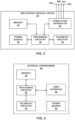
- FIG. 3 is a functional block diagram illustrating various components of an example IMD 20.
- IMD 20 includes processing circuitry 30, memory 32, stimulation generator 34, telemetry circuitry 36, power source 38 and other various hardware components providing functionality for operation of the device.
- IMD 20 includes programmable processing circuitry 30 to be configured to operate according to executable instructions, typically stored in a computer-readable medium or memory 32 such as static, random-access memory (SRAM) device or Flash memory device.
- IMD 20 may include additional discrete digital logic or analog circuitry not shown in FIG. 3 .
- Stimulation generator 34 may connect to one or more medical leads 26A-26D.
- IMD 20 may utilize stimulation generator 34 connected to one or more medical leads 26A-26D to detect and recognize irregularities with the patient requiring treatment and/or therapy based on instructions from processing circuitry 30.
- IMD 20 may utilize stimulation generator 34 connected to one or more medical leads 26A-26D to provide treatment and/or therapy based on instructions from processing circuitry 30.
- Telemetry circuitry 36 may comprise any unit capable of facilitating wireless data transfer between IMD 20 and an external programmer 40, where external programmer 40 may comprise an external medical device, a programming device, a remote telemetry station, a physician-activated device, a patient-activated device, a display device or any other type of device capable of sending and receiving signals to and from IMD 20. Telemetry circuitry 36 and external programmer 40 are respectively coupled to one or more antennas for facilitating the wireless data transfer. Telemetry circuitry 36 may be configured to perform any type of wireless communication. For example, telemetry circuitry 36 may send and receive radio frequency (RF) signals, infrared (IR) frequency signals, or other electromagnetic signals.
- RF radio frequency
- IR infrared
- telemetry circuitry 36 may use sound waves for communicating data or may use the patient's tissue as the transmission medium for communicating with a programmer positioned on the skin of a patient. In any event, telemetry circuitry 36 facilitates wireless data transfer between IMD 20 and external programmer 40.
- Power source 38 may be a rechargeable battery, such as a lithium ion or nickel metal hydride battery. Other rechargeable or conventional batteries may also be used.
- external programmer 40 may be configured to recharge IMD 20 in addition to programming IMD 20.
- FIG. 4 is a functional block diagram illustrating various components of an external programmer 40 for use with IMD 20.
- external programmer 40 includes user interface 54, processing circuitry 50, memory 52, telemetry circuitry 56, and power source 60.
- a clinician or patient interacts with user interface 54 in order to manually change the parameters of a therapy program, change therapy programs within a therapy of programs, view therapy information, view historical therapy regimens, establish new therapy regimens, or otherwise communicate with IMD, such as IMD 20 in FIG. 1 , or view or edit programming information.
- User interface 54 may include a screen and one or more input buttons, allowing external programmer 40 to receive input from a user. Alternatively, or additionally, user interface 54 may additionally, or only, utilize a touch screen display.
- the screen may be a liquid crystal display (LCD), dot matrix display, organic light-emitting diode (OLED) display, touch screen, or any other device capable of delivering and/or accepting information.
- LCD liquid crystal display
- OLED organic light-emitting diode
- Input buttons for user interface 54 may include a touch pad, increase and decrease buttons, emergency shut off button, and other buttons needed to control the therapy, as described above regarding patient programmer 40.
- Processing circuitry 50 controls user interface 54, retrieves data from memory 52 and stores data within memory 52.
- Processing circuitry 50 also controls the wireless transmission of data through telemetry circuitry 56 to an IMD, such as IMD 20 in FIGS. 1-2 , by transmitting data to telemetry circuitry 36 as described in FIG. 3 .
- the transmitted data may include therapy program information specifying various drug delivery program parameters.
- Memory 52 may include operational instructions for processing circuitry 50 and data related to therapy for the patient.
- Power source 60 may be a rechargeable battery, such as a lithium ion or nickel metal hydride battery. Other rechargeable or conventional batteries may also be used.
- external programmer 40 may be used when coupled to an alternating current (AC) outlet, i.e., AC line power, either directly or via an AC/DC adapter. In some examples, external programmer 40 may be configured to recharge IMD 20 in addition to programming IMD 20.
- AC alternating current
- FIG. 5 illustrates an elevated view of the components of fastener device 24 within a medical device 20 having a housing 25 which defines a channel 100 configured to receive an electrical lead 26 or leads 26A and 26B.
- a rotatable member 102 defines a longitudinal axis 104 about which the rotatable member 102 is configured to rotate in a clockwise and/or counterclockwise manner.
- the rotatable member 102 can be constructed out of metal alloys or polymers. Conductive materials can be utilized if rotatable member 102 is desired to be electrically conductive.
- the rotatable member 102 defines an outer surface 106 having a first radius 108 from the longitudinal axis 104.
- a cam lobe 110 extends out from the outer surface 106 farther from the longitudinal axis 104 than the first radius 108 of the outer surface 106.
- the cam lobe 110 defines a substantially planar surface 112 (also shown in FIG. 7 ) parallel to the longitudinal axis 104.
- the substantially planar surface 112 of the cam lobe 110 can be configured to retain the electrical lead 26 within the channel 100.
- the substantially planar surface can be flat, near flat or almost flat, but is not required to be absolutely flat.
- Substantially planar surface 112 may define a midsection 111A between edges 111B and 111C.
- edges 111B and 111C have a larger radius 133 from longitudinal axis 104 than the radius 131 from longitudinal axis 104 to midsection 111A.
- radius 133 is 0.0590 inches (1.4986 mm).
- the 0.005 inch (0.127 mm) is the amount of over-compression the lead has to temporarily endure for the cam lobe to rotate to the substantially planar surface.
- This configuration of midsection 111A between 111B and 111C may resist undesired rotation of rotatable member 1 02 when the lead is retained by cam lobe 110 of rotatable member 102. Further, to minimize the pressure applied to the lead when rotating the cam lobe 110 the curvature could be increased from zero, which would indicate a shape corner, to say RO.O 1 0 indicating a soft corner as shown by edges 111B and 111C in FIG. 5 .
- longitudinal axis 104 is shown as perpendicular to channel 100, the longitudinal axis 104 could also be parallel to or oblique to channel 100 so long as rotation of rotatable member 102 causes cam lobe 110 to extend into channel 100 and against electrical lead 26 within channel 100.
- slider 114 defines a central portion 116 substantially parallel with the channel 100.
- Slider 114 may be made of a metal alloy if it is desirable for slider 114 to be conductive or from a polymer if it is desired for slider 114 to be nonconductive.
- Central portion 116 of slider 114 terminates into a first end 118 and a second end 120 which both extend away from the channel 100 and can be perpendicular to the longitudinal axis 104.
- first end 118 and second end 120 extend in a direction substantially orthogonal from central portion 116.
- the slider 114 can be configured to slide into contact with the electrical lead 26 and secure the electrical lead 26 within the channel 100.
- cam lobe 110 engages the central portion 116 of the slider 114 to apply a force to the central portion 116 which pushes the slider 114 (to the right in FIG. 5 ) toward the channel 100. This action of a slider is discussed in greater detail below with reference to FIGS. 11A-I ).
- a slider protrusion 122 can be located on the central portion 116 of the slider 114 facing the channel 100.
- the slider protrusion 122 defines a substantially planar surface 124 parallel to the channel 100 and the cam lobe 110.
- the slider protrusion 122 can engage the electrical lead 26 as the rotatable member 102 is rotated toward the center portion 116.
- a cam stop 126 can be operably coupled to the first end 118 and can extend inward toward the rotatable member 102 and can run along first end 118.
- the cam stop can be configured to contact and restrict rotation of the rotatable member 102 when the cam lobe 110 engages the cam stop 126 during rotation.
- a retraction member 130 can be operably coupled to the second end 120 and extend toward the rotatable member 102 substantially parallel to the channel 100.
- the retraction member 130 is configured to contact the cam lobe 110 during rotation of the rotatable member 102 in a retraction direction (a counterclockwise direction as shown in FIG. 5 ).
- a retraction direction a counterclockwise direction as shown in FIG. 5 .
- Slider 114 along with rotatable member 102, are housed within chamber 134.
- Slider 114 has a range of motion along motion arrow 132A and arrow 132B.
- cam lobe 110 will either engage center portion 116, cam stop 126 or retraction member 130 at respective circumferential positions of rotatable member 102.
- force from cam lobe 110 will cause slider 114 to slide toward the channel 100 along motion arrow 132B.
- cam stop 126 prevents rotatable member 102 from further rotation in the counterclockwise direction.
- cam lobe 110 when substantially planar portion 112 of cam lobe 110 is substantially parallel with slider center portion 126, this is a "locked position" and the force applied by cam lobe 110 to slider protrusion 122 to lead 26 will hold electrical lead 26 in place.
- cam lobe 110 disengages the center portion 116 and moves until it contacts retraction member 130.
- cam lobe 110 presses against retraction member 130 slider 114 begins to slide away from channel 100 along motion arrow 132A until slider 114 is pushed away from channel 100. If a user keeps rotating rotatable member 102 past retraction member 130, cam lobe 110 will once again contact cam stop 126 which prevents further rotation.
- fastener device 24 may include slider 114, rotatable member 102 may function without slider 114 in other examples.
- FIGS. 6A, 6B and 6C illustrate rotatable member 400.
- a lever 200 can extend from the rotatable member 400 perpendicular to the longitudinal axis 103.
- the lever 200 is configured to rotate the rotatable member 400 about the longitudinal axis 103.
- an intermediary spring member 202 can be optional as a structure (like slider 114) positioned between the cam lobe 190 and electrical lead 26, when the cam lobe 190 is parallel to the channel 100.
- lever 200 is in an extended or released position in which a lead 26 can be inserted into, or removed from, channel 100.
- FIG. 6A Like FIG.
- lever 200 In operation, the user would move lever 200 upward as shown in FIG. 6A .
- An electrical lead 26 can be inserted into channel 100 in this configuration.
- the user could begin moving the lever 2.00 towards connector block 22 and thus begin to turn rotatable member 400 in a counterclockwise direction to rotate cam lobe 190 toward channel 100 as shown in FIG. 6B .
- lever 200 In a locked position, as shown in FIG. 6C , lever 200 has been fully rotated to position cam lobe 190 as resting against spring 202 which in turn rests against the electrical lead 26 to hold lead 26 in place.
- spring 202 may not be used in other examples, so cam lobe 190 contacts the lead.
- FIG. 6A An electrical lead 26 can be inserted into channel 100 in this configuration.
- the user could begin moving the lever 2.00 towards connector block 22 and thus begin to turn rotatable member 400 in a counterclockwise direction to rotate cam lobe 190 toward channel 100 as shown in FIG. 6B .
- FIG. 6C lever
- lever 200 can rest in a lever channel 206 within connector block 22 to make lever 200 both flush with the connector block 22 and retain stop lever 200 at a position where the cam lobe 190 is in the locked position.
- the intermediary spring 202 can include a protrusion or structure configured to impinge or otherwise provide the forces of the cam lobe 190 onto the electrical lead 26. In this manner, spring 202 may prevent the sliding and/or rotation from cam lobe 112 from moving or abrading the electrical lead 26.
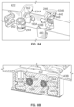
- FIG. 7 illustrates an exploded view of examples of a hex head rotatable member 220 and a lever rotatable member 200 of FIGS. 6A-6C .
- Hex head rotatable member 220 may be like rotatable member 102 of FIG. 5 .
- Lever 200 and intermediary spring 202 are shown in exploded view above a right chamber 434 and hex head rotatable member 220 is shown in exploded view above a left chamber 434. Chambers 434 are adjacent to respective channels 100A and 100B for electrical leads 26.
- Hex head rotatable member 220 has a six-sided hexagonal indentation 222 defined in surface 224. Hexagonal indentation 222 is shaped to receive an Allen wrench. The Allen wrench (not shown) is used by placing one end of an Allen wrench within the hexagonal indentation 222. The other end of the Allen wrench is then held by a hand of a user to rotate rotatable member 220. Hex head rotatable member 200 is also shown having a cam lobe 410 which would also rotate as rotatable member 220 is rotated.
- Both rotatable member 200 and 220 are placed within chambers 434 and flush mounted covers 230 are placed over chambers 434 to make connector block 22 flush on the surface and smooth for implantation. Covers 230 may be glued, welded, or otherwise fixed in place to connector block 22. Although connector block 22 is shown, rotatable members 200 and 220 may be placed directly within a housing of the medical device in other examples.
- FIGS. 8A and 8B illustrate rotatable members 420 and 440 in a fully assembled configuration. As shown, hexagonal rotatable member 420 and slotted rotatable member 440 are shown being inserted into chambers 534A and 534B of connector block 422. With reference to FIG. 8A , hexagonal rotator member 420 and slotted member 440 are being inserted into chambers 534 A and 534B respectively. It is of note, hexagonal rotator member 420 and slotted member 440 could be swapped into either chambers 534B and 534A as the same parts fit both chambers 534A and 534B.
- a ledge 242 (shown in chamber 534A) can traverse around a midsection surface of chambers 534A and 534B and at corresponding locations of respective covers 430.
- the ledge 242 can engage rotatable member slot 246 and provide support to hold rotatable member 420 and 440 securely within chambers 534A and 534B.
- Ledge 242 assures rotatable members 420 and 440 are held within chambers 534A and 534B.
- Ledge 242 rests within channel 244, which retains rotatable member 420 and 440 within chambers 534A and 534B respectively.
- Ledge 241 allows rotatable member 420 and 440 to also rotate freely within chamber 534A and 534B respectively while also retaining rotatable member 420 and 440 within chambers 534A and 524B. This ensures rotatable members cannot become lose within chambers 534A and/or 534B and possibly become lost or disassociated from IMD 20.
- Slotted rotatable member 440 defines a slot 246 bisecting surface 248. Slot 246 is configured to receive a standard screwdriver which can rotate slotted rotatable member 440.
- the standard screwdriver can be used similarly to an Allen wrench to rotate the rotatable member 440.
- both rotatable member 420 and rotatable member 440 could be a hex head rotatable member like rotatable member 420 or both could be a slotted rotatable member like rotatable member 440.
- FIG. 8B a cross-section of the connector block 422 is shown with hexagonal rotatable member 420 and slotted rotatable member 440 installed. As shown both rotatable members 420 and 440 have their cam lobes 510A and 510B respectively in a "locked position" where electrical leads 226A and 226B are held in frictional position by the cam lobes 510A and 510B. It's of note neither rotatable member 420 nor 440 utilizes an intermediary spring 202.
- a slotted hexagonal rotatable member 275 is shown. As shown rotatable members 275 has cam lobe 281 and hex-slotted recess 280. Rotatable member 275 could be used with most any type of implant tool, such as a standard screwdriver or an Allen wrench.
- the hex-slotted recess 280 allows for an implanting physician to utilize either a standard screwdriver or an Allen wrench for coupling of the electrical lead to the IMD.
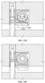
- FIGS. 9A and 9B are a conceptual diagram of a rotating member 502 within a chamber 634 which provides hard stops to prevent rotation of rotating member 502 beyond certain circumferential positions for the rotating member 502.
- Chamber 634 can provide built in hard stops for rotating member 502.
- Hard stops can assist an implantation physician with determining when the rotating member 502 is in the "locked position” and the "unlocked position.” Without hard stops 300 and 302, rotating member 502 would continue to rotate in response to rotational force from the implantation physician. Thus, the physician may have difficulty identifying the fully “locked position” or an "unlocked position” by feel alone. Therefore, hard stops 300 and 302 may facilitate correct positioning of the rotatable member with respect to the lead 326.
- cam lobe 210 When rotatable member 502 is rotated in a clockwise direction, cam lobe 210 will eventually contact hard stop 302, as shown in FIG. 9B , and stop rotating. In this position, rotatable member is in a substantially "locked position" at which cam lobe 210 has engaged electrical lead 326 within channel 100.
- the implanting physician could simply turn the rotatable member 502 counterclockwise a short distance to fully engage the substantially planar surface 212 against electrical lead 326 thus providing a more secure electrical lead retaining position.
- the implanting physician should be able to feel the rotating member 502 substantially planar surface 212 engaging electrical lead 326 and being slightly harder to turn in a counterclockwise motion as the electrical lead 2626 would provide resistance force to the rotating movement.
- the hard stop 302 could be set so the cam lobe 210 is in the "locked position" when the cam lobe 210 is engaged with hard stop 302.
- Another alternative is to provide for the forces against cam lobe edge 212A of planar surface 212 to cause the cam lobe 210 to settle with the planar surface 212 against the lead 326.
- the implanting physician would turn the rotatable member 502 in a counterclockwise direction.
- the implanting physician could rotate the rotatable member 502 until the cam lobe 210 engaged hard stop 300 indicating the rotatable member 502 is in an "unlocked position" at which the lead 326 may be removed from the channel 100.
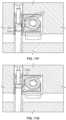
- FIGS. 10A and 10B are conceptual diagrams illustrating an example of an intermediary impinger 600 configured to mechanically connect a medical lead to an IMD.
- Intermediary impinger 600 can behave like spring 202 of FIGS. 6A-6C .
- Intermediary impinger 600 can function to convert the rotational motion of rotational member 320 into linear movement from cam lobe 310 forces against intermediary impinger 600 to electrical lead 26 within channel 700. Utilizing an intermediary impinger 600 can reduce or prevent movement of the electrical lead 26 from causing rotation of the rotatable member 320.
- impinger 600 prevents this movement from being transferred to rotatable member 320, as impinger 600 cannot move in a direction parallel with the channel 700. If the impinger 700 were not present, the parallel force could pull the cam lobe 310 and cause rotation of rotatable member 320 until the cam lobe 310 no longer locked the lead 26 in place.
- intermediary impinger 700 has an "X"-shaped protrusion 304, which when cam lobe 310 engages contact surface 306, protrusion 304 extends toward channel 700 and engages electrical lead 26.
- Protrusion 304 may be configured to have any type of structure or include a plurality of discontinuous projections.
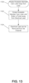
- FIGS. 11A-I illustrate a process of insertion and retention of an electrical lead within an IMD utilizing a slider and rotatable member. Electrical lead 426 is shown being inserted within channel 800 in the example FIG. 11A (see state 1000 FIG. 12 ).
- FIG. 11B lead 426 is fully inserted within channel 800.
- FIG. 11C in which the lead is fully inserted into channel 800, an implanting physician can engage an Allen wrench in hexagonal indentation 322 and begin turning hex head rotatable member 402 clockwise (see state 1 002 FIG. 12 ). Rotation of rotatable member 402 causes cam lobe 610 to contact and push slider 214 towards the lead 426 in channel 800 in. Slider 214 moves toward lead 436 in chamber 234, which is shown by cam lobe 610 moving away from retraction member 330.
- hex head rotatable member 402 continues to move in a clockwise direction and now cam lobe corner 602 engages slider center portion 216 and applies a force to slider 214 in the direction of channel 800 to push slider 214 towards channel 800 and the lead 426 so slider protrusion 522 begins to engage the electrical lead 426 (see state 1004 at FIG. 12 ).
- hex head rotatable member 402 continues to move in a clockwise direction and in FIG. 11F is in a "locked position", where the substantially planar surface 312 of cam lobe 610 is substantially parallel with the substantially planar surface 324 of slider protrusion 622 (see state 1006 FIG. 12 ).
- cam lobe 610 will engage cam stop 526.
- Slider 214 is still holding the electrical lead 426 even though the implanting physician has rotated past the "locked position.”
- the lead 426 will likely push back against the slider 214, which would center the cam lobe 610 again on the slider 214 to the equilibrium of the "locked position" of FIG. 11F which has a predetermined amount of force and pressure against the lead 426 for retention.
- a lead may need to be removed from a medical device.
- the implanting physician may release the electrical lead 426 from channel 800 by using an Allen wrench again to rotate hex head rotatable member 402 in a counterclockwise direction.
- cam lobe 610 is rotated away from lead 426 and is now facing slider second end 520 (see state 1100 in FIG. 13 ).
- cam lobe corner 602 engages retraction member 530.
- cam lobe corner 602 pushes against the retraction member 530 to slide the slider 214 in a direction away from channel 800 and electrical lead 426 (see state 1102 in FIG. 13 ). Therefore, pulling slider 214 away from the lead 426 may overcome tissue ingress or other frictional forces otherwise holding the electrical lead 426 within the channel 800. Once the slider 214 is pulled away from electrical lead 426, then the implanting physician can remove electrical lead 426 from channel 800 (see state 1104 of FIG. 13 ).
- FIGs. 11J, 11K, 11L and 11M are conceptual diagrams illustrating an example slider device for securing a medical lead to an IMD with a rotatable member.
- Sliders 1100, 1102, 1104 and 1106 all represent various examples of sliders which could be used to retain an implantable lead within a medical device in use with a rotatable member.
- Each of the slider protrusions for each of sliders 1100, 1102, 1104 and 1106 all provide unique differences all depending on the desired hold on the implantable lead or for the application the implantable lead is being used.
- Slider protrusion 1108 shows an elongated concave structure. Slider protrusion 1108 allows the slider 1 100 to better accept the implantable lead as the elongated concave structure is almost the same shape as out outer shell of an implantable lead. Thus, less force to placed upon an implantable lead and less risk of deformation of the implantable lead is realized as there are no pointed protruding surfaces in contact with the implantable lead.
- Slide protrusion 1110 shows a dual ripple structure. Slider 1102 can localize the force applied to an implantable lead to two spots. Thus, the force exerted on the implantable lead would be localized to two spots.
- slide protrusions 1112 and 1114 which provide a distribution of the forces along the protrusions 1112 and 1114.
- slider protrusion 1114 has a rounded edge and thus the force would be distributed along the slider protrusion with most of the force coming from the largest extending radius, which is in the middle of the slider protrusion.
- the protrusion 1112 is substantially flat, as discussed above, so the force is distributed equally along protrusion 1112.
- processors or processing circuitry including one or more microprocessors, digital signal processors (DSPs), application specific integrated circuits (ASICs), field programmable gate arrays (FPGAs), or any other equivalent integrated or discrete logic circuitry, as well as any combinations of such components.
- DSPs digital signal processors
- ASICs application specific integrated circuits
- FPGAs field programmable gate arrays
- processing circuitry or “processing circuitry” may generally refer to any of the foregoing logic circuitry, alone or in combination with other logic circuitry, or any other equivalent circuitry.
- a control unit including hardware may also perform one or more of the techniques of this disclosure.
- Such hardware, software, and firmware may be implemented within the same device or within separate devices to support the various operations and functions described in this disclosure.
- any of the described units, circuits or components may be implemented together or separately as discrete but interoperable logic devices. Depiction of different features as circuits or units is intended to highlight different functional aspects and does not necessarily imply such circuits or units must be realized by separate hardware or software components. Rather, functionality associated with one or more circuits or units may be performed by separate hardware or software components or integrated within common or separate hardware or software components.
- Computer readable storage media may include random access memory (RAM), read only memory (ROM), programmable read only memory (PROM), erasable programmable read only memory (EPROM), electronically erasable programmable read only memory (EEPROM), flash memory, a hard disk, a CD-ROM, a floppy disk, a cassette, magnetic media, optical media, or other computer readable media.
- RAM random access memory
- ROM read only memory
- PROM programmable read only memory
- EPROM erasable programmable read only memory
- EEPROM electronically erasable programmable read only memory
- flash memory a hard disk, a CD-ROM, a floppy disk, a cassette, magnetic media, optical media, or other computer readable media.
Landscapes
- Health & Medical Sciences (AREA)
- Engineering & Computer Science (AREA)
- Biomedical Technology (AREA)
- Nuclear Medicine, Radiotherapy & Molecular Imaging (AREA)
- Radiology & Medical Imaging (AREA)
- Life Sciences & Earth Sciences (AREA)
- Animal Behavior & Ethology (AREA)
- General Health & Medical Sciences (AREA)
- Public Health (AREA)
- Veterinary Medicine (AREA)
- Electrotherapy Devices (AREA)
Description
- The disclosure is related to medical devices, and more specifically, devices, systems, and techniques for temporarily securing elongated members to medical devices.
- Medical devices, which included external or implantable medical devices (IMDs), may be used to treat a variety of medical conditions. Some medical devices may be attached to medical leads for sensing and/or delivery of electrical stimulation therapy to a patient via implanted electrodes. For example, an implantable electrical stimulation device may include an electrical stimulation generator and be attached to one or more implantable leads carrying one or more electrodes. In some cases, implantable electrodes may be coupled to an external medical device including an electrical stimulation generator via one or more percutaneous leads or fully implanted leads.
- Example IMDs may be configured to function as neurostimulators, cardiac monitors, cardiac defibrillators, cardiac pacemakers and others. Electrical stimulation therapy may include stimulation of nerve, muscle, or brain tissue or other tissue within a patient. An electrical stimulation device may be fully implanted within the patient. Medical electrical stimulators have been proposed for use to relieve a variety of symptoms or conditions such as heart disease, chronic pain, tremor, Parkinson's disease, depression, epilepsy, migraines, urinary or fecal incontinence, pelvic pain, sexual dysfunction, obesity, and gastro paresis. An electrical stimulator may be configured to deliver electrical stimulation therapy via medical leads carrying electrodes implantable proximate to the heart, spinal cord, pelvic nerves, gastrointestinal organs, peripheral nerves, or within the brain of a patient. Stimulation proximate the spinal cord, within the brain, and proximate peripheral nerves are often referred to as spinal cord stimulation (SCS) deep brain stimulation (DBS), and peripheral nerve stimulation (PNS), respectively.
US Patent N° 6,741,892 discloses a known system for securing the proximal end of a medical lead to a IMD. - This disclosure includes devices, systems, and techniques for securing the proximal end of a medical lead to an IMD with a fastener device incorporating a rotating member having a cam lobe. The cam lobe may be formed to have a substantially planar surface configured to contact the medical lead. For example, rotation of the rotating member can cause the substantially planar surface of the cam lobe to be disposed against the medical lead and provide a bias force resisting linear movement of the medical lead. In some examples, the rotating member and cam lobe can be used to impart a linear motion to a slider, intermediary impinger, or spring, which in turn is disposed against the medical lead providing a bias force resisting linear movement.
- In one example, a medical device includes a housing having a channel configured to receive an electrical lead. The medical device can further have a rotatable member having a longitudinal axis about which the rotatable member is configured to rotate. The rotatable member can have an outer surface having a first radius from the longitudinal axis. The rotatable member can also have a cam lobe extending farther from the longitudinal axis than the first radius of the outer surface. The cam lobe can have a substantially planar surface parallel to the longitudinal axis. The substantially planar surface of the cam lobe can be configured to retain the electrical lead within the channel. The rotatable member can further have a lever extending from the rotatable member perpendicular to the longitudinal axis. The medical device can further have a slider having a central portion substantially parallel with the cam lobe. The central portion can terminate in a first end and a second end where both the first end and the second end extend away from the channel. The slider can further have a slider protrusion on the central portion of the slider. The slider protrusion can have a substantially planar surface parallel to the channel. The slider protrusion can be configured to engage the electrical lead as the rotatable member is rotated toward the center portion. The slider can further have a cam stop operably coupled to the first end and extending inward toward the rotatable member, substantially parallel with the first end. The cam stop can be configured to contact and restrict rotation of the rotatable member when the cam lobe engages the cam stop. The slider can further have a retraction member operably coupled to the second end and extending toward the rotatable member substantially parallel to the channel. The retraction member can be configured to contact the cam lobe during rotation of the cam lobe in a retraction direction. The cam lobe can be configured to engage the retraction member as the slider is pulled away from the channel.
- In another example, a medical system having a medical device including a housing with a first channel configured to receive a first electrical lead. The medical device further can have a first rotatable member with a longitudinal axis about which the first rotatable member is configured to rotate. The first rotatable member can have an outer surface having a first radius. Further, the rotatable member can have a cam lobe extending farther from the longitudinal axis than the first radius of the outer surface. The cam lobe can have a substantially planar surface parallel to the longitudinal axis. The substantially planar surface of the cam lobe can be configured to retain the first electrical lead within the first channel. The medical device housing can further have a second channel defined by the housing configured to receive a second electrical lead and have a second rotatable member having a longitudinal axis about which the second rotatable member is configured to rotate. The second rotatable member can also have an outer surface having a first radius. The second rotatable member can also have a cam lobe extending farther from the longitudinal axis than the first radius of the outer surface. The cam lobe can have a substantially planar surface parallel to the longitudinal axis. The substantially planar surface of the cam lobe is configured to retain the second electrical lead within the second channel. The medical device can further have a first slider substantially encompassing the first rotatable member. The first slider is slidably mounted and configured to slide toward the first channel as the rotatable member rotates the cam lobe towards a central portion of the first slider. The central portion can be substantially parallel with the first channel. The first slider can have a retraction member located opposite of the central portion across from the rotatable member and substantially parallel to the central portion. The cam lobe can be configured to engage the retraction member as the cam lobe is rotated away from the central portion to move the slider away from the first channel. The medical device can further have a stimulation generator configured to generate electrical stimulation deliverable via one or more electrodes of the electrical lead.
- In another example, a medical device having a housing with a channel configured to receive an electrical lead and a chamber adjacent to the channel. The medical device can further have a rotatable member located within the chamber. The rotatable member can have an outer surface having a first radius and a cam lobe extending farther from the first radius of the outer surface. The cam lobe can have a substantially planar surface parallel to the longitudinal axis. The medical device can further have a slider having a central portion substantially parallel with the cam lobe. The central portion can terminate in a first end and a second end where both the first end and the second end extend away from the channel. The slider can be configured to slide into contact with the electrical lead and secure the electrical lead within the channel. The cam lobe can be configured so as the rotatable member is rotated and the cam lobe engages the central portion of the slider, it pushes on the central portion to move the slider toward the channel. The slider can further have a slider protrusion on the central portion of the slider. The slider protrusion can have a substantially planar surface parallel to the channel. The slider protrusion can be configured to engage the electrical lead as the rotatable member is rotated toward the center portion. The slider can further have a cam stop operably coupled to the first end and extending inward toward the rotatable member, substantially parallel with the first end. The cam stop can be configured to contact and restrict rotation of the rotatable member when the cam lobe engages the cam stop. The slider may further have a retraction member operably coupled to the second end and extending toward the rotatable member substantially parallel to the channel. The retraction member can be configured to contact the cam lobe during rotation of the cam lobe in a retraction direction. The cam lobe can be configured to engage the retraction member as the slider is moved away from the channel.
- The details of one or more examples of this disclosure are set forth in the accompanying drawings and the description below. Other features, objects, and advantages of this disclosure will be apparent from the description and drawings. The present invention is set out in the appended claims.
-
-
FIG. 1 is a conceptual diagram of a medical system including an IMD with medical leads configured to deliver gastric stimulation therapy. -
FIG. 2 is a conceptual diagram of an example IMD with a fastener device configured to secure a medical lead to the IMD. -
FIG. 3 is a functional block diagram of an example IMD configured to deliver stimulation therapy. -
FIG.4 is a functional block diagram of an example external programmer configured to communicate with the IMD ofFIG. 3 . -
FIG. 5 is a conceptual diagram of an example fastener device, including a rotatable member with a cam lobe configured to actuate a slider. -
FIGS. 6A, 6B, and 6C are conceptual diagrams of an example rotatable member configured to actuate on a spring member. -
FIG. 7 is an exploded diagram of an example hex head rotatable member and an example lever rotatable member. -
FIGS. 8A and 8B are conceptual diagrams of an example rotatable member configured to mechanically retain a medical lead to an IMD. -
FIG. 8C is a conceptual diagram of an example hexagonal rotatable member configured to mechanically retain a medical lead to an IMD. -
FIGS. 9A and 9B are a conceptual diagram of an example rotatable member within a chamber defining hard stops. -
FIGS. 10A and 10B are conceptual diagrams of an example intermediary impinger configured to mechanically hold a medical lead within an IMD. -
FIGS. 11A ,11B, 11C , 1D,11E ,11F ,11G ,11H and 11I are conceptual diagrams illustrating an example device and technique for securing a medical lead to an IMD with a rotatable member. -
FIGs. 11J, 11K, 11L and 11M are conceptual diagrams illustrating an example slider device for securing a medical lead to an IMD with a rotatable member. -
FIG. 12 is a flowchart diagram of a process for inserting and securing a lead. -
FIG. 13 is a flowchart diagram of a process for removing a lead. - This disclosure includes devices, systems, and techniques for securing the proximal end of a medical lead to a medical device, such as an IMD, with a cam based rotating fastener device. To retain a lead (or drug catheter in other examples) in an IMD, the IMD may utilize a set screw, which when advanced toward the lead, applies a force directly to the side of the lead housing or metal band around the housing of the lead. Friction forces and/or deformation caused by the set screw may prevent the lead from being pulled out from the IMD. The depth and force of the set screw is determined by the physician manually rotating the screw. However, if the physician over rotates the set screw, the force applied to the lead from the set screw may deform the lead and cause damage to the lead housing and/or elements within the lead, such as one or more electrical conductors. A damaged lead may need to be replaced or, if not replaced, prevent full operation of the medical device and/or lead.
- As described herein, a cam lobe on the side of a rotatable member of a fastener may be configured to applying a force directly to the side of a lead with a limited distance the cam lobe can travel towards the side of the lead. The cam lobe may also define a substantially planar surface contacting the side of the lead to secure the lead and resist movement of the cam lobe due to axial force from the lead. This cam lobe thus avoids potential deformation of the lead. The cam fastener can also provide a very low-profile height compared to a set screw since it operates on the side of the cable rather than the top. Further, a portion of the set screw height is the additional needed height for movement (e.g., the extra rotational movement needed) and a retaining feature above the screw threads). A rotatable member's height of examples described below can be anywhere from 0.040 inches (1.02 mm) to 0.060 inches (1.52 mm) smaller than a set screw. Further, the rotatable member does not stick out away from the implantable device, thus creating a smooth profile for a flush profile surface. In one example, the volume occupied by rotatable member is, 0.0023 cubic inches (0.0377 cubic cm), which may be comparable to or less than set screws, which may be used to retain a lead in other examples. Even when the rotatable member is used in combination with an intermediate member the volume occupied may be between 0.002 and 0.003 cubic inches (0.032 and 0.049 cubic cm) in some examples.
- The cam lobe shape provides a positive engagement feel for the implanting physician, has a low assembly height and provides permanent fastener retention. The substantially planar surface helps prevent any deformation from over rotation of a set screw. The force applied by the cam lobe is not dependent on the implanting physician, but instead is dependent upon whether the cam lobe is engaged with the lead or not. The substantially planar surface provides a "locking", "anti-rotation", or "resting position" action provided by the lobe's "substantially planar surface". The medical lead elastically deforms and provides a spring back return force to the lobe's planar surface. The elastic deformation force would need to be overcome for the cam to be turned out of its resting (locked) position.
- Further, the cam shape cannot crush the implantable lead because the cam lobe has a fixed distance it extends toward the lead. Furthermore, an intermediate member can be added between the cam member and the lead to control the contact area and secure leads without axial force or movement. The intermediate member can be used to prevent abrasion to the lead as the intermediate member does not move or rotate as the rotatable member does. A rotatable cam provides simple operation, can be configured for standard tools (e.g., an Allen wrench, slotted screwdriver, hand operated lever, etc.) and can provide visual cues for the physician installing the IMD.
- As described herein, a connector block may be referred to as a header of the IMD in some examples. Structures for retaining a medical lead may include actuatable cam mechanisms configured to mechanically connect a medical lead to an IMD. Such a flexible clamping mechanism may be located adjacent, near or next to channels configured to receive the proximal end of a medical lead. Actuating the rotatable cam mechanism may apply a compressive force to a medical lead in the proximal end of the medical lead, thereby mechanically connecting the medical lead to the rotating cam member.
- For purposes of this disclosure the term "substantially" when used in relation to describing elements, shall be defined as being largely and or wholly the item specified. When used in relation to quantities, it can mean considerable in quantity; significantly great.
-
FIG. 1 illustrates an examplemedical system 10 including anIMD 20 with a medical lead(s) 26A, 26B (hereinafter referred to collectively as leads 26 or leads 26A, 26B, 26C, 26D) configured to deliver therapy.IMD 20 is configured to deliver therapy topatient 12 through medical leads 26. Medical lead(s) 26 are connected toIMD 20 byconnector block 22. In some references, a connector block, such asconnector block 22, is instead referred to as a header of the IMD. In any event,connector block 22 provides the means for forming an electrical connection between electrical contacts ofmedical lead 26 and feedthrough pins of feedthroughs passing through the housing ofIMD 20, which forms a hermetically sealed enclosure for the electronic components ofIMD 20. In other examples, a portion ofIMD 20 may accept a lead and provide electrical contact with a hermetic seal without being arranged as a separate header or connector block. -
IMD 20 may include a power source as well as processing circuitry, microprocessors, internal memory, and other electronic circuitry for executing software or firmware to provide the functionality described herein. The software executing thereon may perform a variety of sensing, diagnostic, and/or therapy-related operations, one such therapy operation may be stimulation ofspinal cord 14 throughmedical lead 26 operatively (i.e. electrically and/or mechanically) connected toIMD 20 byconnector block 22. -
Connector block 22. is configured to receive the proximal end ofmedical lead 26.Connector block 22 includes one or more fasteners with actuatable clamps, such as fastener device 24 (shown inFIG. 5 ), which are configured to secure the proximal end of one or moremedical leads 26 toIMD 20. -
Medical system 10 further includesexternal programmer 40. In different examples,external programmer 40 may include an external medical device, a programming device, a remote telemetry station, a physician-activated device, a patient-activated device, a display device or any other type of device capable of sending and receiving signals to and fromIMD 20. In some implementations,IMD 20 generates content to display onexternal programmer 40. In other implementations,external programmer 40 communicates instructions toIMD 20 based on the content received from a cloud server, a computer system, and/or a mobile device. - As described herein,
IMD 20, and the software executing thereon, provides a platform for providing therapy tospinal cord 14 through medical lead(s) 26. For example,IMD 20 may be configured to receive and process electrical signals produced by the body ofpatient 12 using medical lead(s) 26.IMD 20 may also use medical lead(s) 26 to deliver therapy, such as SCS therapy, tospinal cord 14 ofpatient 12. In other examples, one or moremedical leads 26 may be dedicated byIMD 20 to receive electrical signals, and one or more othermedical leads 26 may be dedicated to delivering therapy tospinal cord 14 ofpatient 12. - In some examples,
IMD 20 may implement techniques for automated receiving and processing of electrical signals indicating a need for therapy. For example,IMD 20 may allow a user, by communicating withexternal programmer 40, control over one or more therapy techniques used byIMD 20 in response toIMD 20 receiving and processing electrical signals frommedical lead 26 indicating a need for treatment. In another example, a user may useexternal programmer 40 to provide pre-determined responses for therapy throughmedical lead 26 to respond toIMD 20 receiving and processing electrical signals frommedical lead 26 indicating a need for treatment. - In the example of
FIG. 1 ,IMD 20 is illustrated as an IMD for providing therapy to a spinal cord. However, in other examples,IMD 20 may be configured to function as a neurostimulator, cardiac monitor, cardiac defibrillator, cardiac pacemakers, or any other type of simulation and/or sensing device utilizing one or more medical leads. - As described herein, IMDs deliver therapy through one or more
medical leads external programmer 40 and/or internal programming for software which, as described, can efficiently deliver therapy to targeted areas. In this example,connector block 22 may be the result of multiple components. - Medical leads 26A, 26B may include one or more electrodes. In the example illustrated,
medical leads medical leads - Medical leads 26A, 26B are connected at a proximal end to
IMD 20 byconnector block 22.Connector block 22 may include one or more fasteners, such as fastener device 24 (seeFIG. 5 ) interconnecting with one or more contact rings located on the proximal end ofmedical leads housing 25. One or more conductors (not shown) extend withinmedical leads medical leads medical lead 26A fromconnector block 22 and operatively couple to the tip electrode and a second electrical conductor can extend along the length of the body ofmedical lead 26A fromconnector block 22 and operatively couple to the ring electrode. The respective conductors may be operatively coupled to circuitry, such as astimulation generator 34 as described inFIG. 3 , ofIMD 20 via connections inconnector block 22. - In different examples,
stimulation 28 may instead include peripheral nerve stimulation (PNS) or peripheral nerve field stimulation (PNFS) therapy, and/or any other stimulation provided by a neurostimulator, a cardiac monitor, a cardiac defibrillator, a cardiac pacemaker, or any other type of mobile or non-mobile computing device suitable for performing the techniques described herein. -
IMD 20 may also provide sensing functions in addition to or alternatively to stimulation functions. For example,IMD 20 may be configured to receive and process electrical signals produced by the body ofpatient 12 usingmedical leads IMD 20,IMD 20 may respond by usingmedical leads stimulation 28, to the body ofpatient 12. In other examples, one or moremedical leads IMD 20 to receiving electrical signals and/or delivering therapy, such asstimulation 28 to the body ofpatient 12. -
IMD 20 is illustrated as an IMD for providing therapy to the torso ofpatient 12. However, in other examples,IMD 20 may be a neurostimulator, cardiac monitor, cardiac defibrillator, cardiac pacemaker or any other type of mobile or non-mobile computing device suitable for performing the techniques described herein. -
Housing 25 ofIMD 20 can be constructed of conductive materials, nonconductive materials or a combination thereof. As described herein,housing 25 ofIMD 20 may provide a substantially sealed environment for processing circuitry, memories, transmitters, receivers, transceivers, sensors, sensing circuitry, therapy circuitry, antennas, power sources, and other components ofIMD 20. In the example ofFIG. 1 ,IMD 20 delivers therapy through one or moremedical leads IMD 20 byconnector block 22 utilizing one or more fasteners, such asfastener device 24 as described inFIG. 5 . -
FIG. 3 is a functional block diagram illustrating various components of anexample IMD 20. As shown inFIG. 3 ,IMD 20 includesprocessing circuitry 30,memory 32,stimulation generator 34,telemetry circuitry 36,power source 38 and other various hardware components providing functionality for operation of the device. For example,IMD 20 includesprogrammable processing circuitry 30 to be configured to operate according to executable instructions, typically stored in a computer-readable medium ormemory 32 such as static, random-access memory (SRAM) device or Flash memory device.IMD 20 may include additional discrete digital logic or analog circuitry not shown inFIG. 3 . -
Stimulation generator 34 may connect to one or moremedical leads 26A-26D.IMD 20 may utilizestimulation generator 34 connected to one or moremedical leads 26A-26D to detect and recognize irregularities with the patient requiring treatment and/or therapy based on instructions from processingcircuitry 30. In some examples,IMD 20 may utilizestimulation generator 34 connected to one or moremedical leads 26A-26D to provide treatment and/or therapy based on instructions from processingcircuitry 30. -
Telemetry circuitry 36 may comprise any unit capable of facilitating wireless data transfer betweenIMD 20 and anexternal programmer 40, whereexternal programmer 40 may comprise an external medical device, a programming device, a remote telemetry station, a physician-activated device, a patient-activated device, a display device or any other type of device capable of sending and receiving signals to and fromIMD 20.Telemetry circuitry 36 andexternal programmer 40 are respectively coupled to one or more antennas for facilitating the wireless data transfer.Telemetry circuitry 36 may be configured to perform any type of wireless communication. For example,telemetry circuitry 36 may send and receive radio frequency (RF) signals, infrared (IR) frequency signals, or other electromagnetic signals. Any of a variety of modulation techniques may be used to modulate data on a respective electromagnetic carrier wave. Alternatively,telemetry circuitry 36 may use sound waves for communicating data or may use the patient's tissue as the transmission medium for communicating with a programmer positioned on the skin of a patient. In any event,telemetry circuitry 36 facilitates wireless data transfer betweenIMD 20 andexternal programmer 40. -
Power source 38 may be a rechargeable battery, such as a lithium ion or nickel metal hydride battery. Other rechargeable or conventional batteries may also be used. In some examples,external programmer 40 may be configured to rechargeIMD 20 in addition to programmingIMD 20. -
FIG. 4 is a functional block diagram illustrating various components of anexternal programmer 40 for use withIMD 20. As shown inFIG. 4 ,external programmer 40 includesuser interface 54, processing circuitry 50,memory 52,telemetry circuitry 56, and power source 60. A clinician or patient interacts withuser interface 54 in order to manually change the parameters of a therapy program, change therapy programs within a therapy of programs, view therapy information, view historical therapy regimens, establish new therapy regimens, or otherwise communicate with IMD, such asIMD 20 inFIG. 1 , or view or edit programming information. -
User interface 54 may include a screen and one or more input buttons, allowingexternal programmer 40 to receive input from a user. Alternatively, or additionally,user interface 54 may additionally, or only, utilize a touch screen display. The screen may be a liquid crystal display (LCD), dot matrix display, organic light-emitting diode (OLED) display, touch screen, or any other device capable of delivering and/or accepting information. - Input buttons for
user interface 54 may include a touch pad, increase and decrease buttons, emergency shut off button, and other buttons needed to control the therapy, as described above regardingpatient programmer 40. Processing circuitry 50controls user interface 54, retrieves data frommemory 52 and stores data withinmemory 52. Processing circuitry 50 also controls the wireless transmission of data throughtelemetry circuitry 56 to an IMD, such asIMD 20 inFIGS. 1-2 , by transmitting data totelemetry circuitry 36 as described inFIG. 3 . The transmitted data may include therapy program information specifying various drug delivery program parameters.Memory 52 may include operational instructions for processing circuitry 50 and data related to therapy for the patient. - Power source 60 may be a rechargeable battery, such as a lithium ion or nickel metal hydride battery. Other rechargeable or conventional batteries may also be used. In some cases,
external programmer 40 may be used when coupled to an alternating current (AC) outlet, i.e., AC line power, either directly or via an AC/DC adapter. In some examples,external programmer 40 may be configured to rechargeIMD 20 in addition to programmingIMD 20. -
FIG. 5 illustrates an elevated view of the components offastener device 24 within amedical device 20 having ahousing 25 which defines achannel 100 configured to receive anelectrical lead 26 or leads 26A and 26B. Arotatable member 102 defines alongitudinal axis 104 about which therotatable member 102 is configured to rotate in a clockwise and/or counterclockwise manner. Therotatable member 102 can be constructed out of metal alloys or polymers. Conductive materials can be utilized ifrotatable member 102 is desired to be electrically conductive. Therotatable member 102. defines anouter surface 106 having afirst radius 108 from thelongitudinal axis 104. A cam lobe 110 extends out from theouter surface 106 farther from thelongitudinal axis 104 than thefirst radius 108 of theouter surface 106. The cam lobe 110 defines a substantially planar surface 112 (also shown inFIG. 7 ) parallel to thelongitudinal axis 104. The substantiallyplanar surface 112 of the cam lobe 110 can be configured to retain theelectrical lead 26 within thechannel 100. As discussed above, the substantially planar surface can be flat, near flat or almost flat, but is not required to be absolutely flat. - Substantially
planar surface 112 may define amidsection 111A betweenedges edges larger radius 133 fromlongitudinal axis 104 than theradius 131 fromlongitudinal axis 104 tomidsection 111A. From the Pythagorean theorem: c=(a2+b2)1/2, we know if "a" (e.g., the radius 131) remains constant and "b" (e.g., the length of the substantially planar surface 112) increases, then "c" (the radius 133) will increase as well. More succinctly expressed, if "a" remains constant and "b" increases, then "c" will increase as well. Thus, in one example, if the flat surface 110 of thecam 131 is 0.0540 inches (1.3716 mm) and the substantiallyplanar surface 112 is 0.0540 inches (1.397 mm), thenradius 133 is 0.0590 inches (1.4986 mm). In this manner, a larger rotational force is needed to rotaterotatable member 102 and overcome the larger radius and force applied by either ofedges smaller radius 131 tomidsection 111A will require. The dimensional difference between theradius 133 and theradius 131 is 0.059 - 0.054 = 0.005 inches (1.4986 - 1.3716 = 0.127mm). The 0.005 inch (0.127 mm) is the amount of over-compression the lead has to temporarily endure for the cam lobe to rotate to the substantially planar surface. This configuration ofmidsection 111A between 111B and 111C may resist undesired rotation of rotatable member 1 02 when the lead is retained by cam lobe 110 ofrotatable member 102. Further, to minimize the pressure applied to the lead when rotating the cam lobe 110 the curvature could be increased from zero, which would indicate a shape corner, to say RO.O 1 0 indicating a soft corner as shown byedges FIG. 5 . - While the
longitudinal axis 104 is shown as perpendicular tochannel 100, thelongitudinal axis 104 could also be parallel to or oblique to channel 100 so long as rotation ofrotatable member 102 causes cam lobe 110 to extend intochannel 100 and againstelectrical lead 26 withinchannel 100. - Further shown in
FIG. 5 , slider 114 defines acentral portion 116 substantially parallel with thechannel 100. Slider 114 may be made of a metal alloy if it is desirable for slider 114 to be conductive or from a polymer if it is desired for slider 114 to be nonconductive.Central portion 116 of slider 114 terminates into a first end 118 and asecond end 120 which both extend away from thechannel 100 and can be perpendicular to thelongitudinal axis 104. In some examples, first end 118 andsecond end 120 extend in a direction substantially orthogonal fromcentral portion 116. The slider 114 can be configured to slide into contact with theelectrical lead 26 and secure theelectrical lead 26 within thechannel 100. When therotatable member 102 is rotated (e.g., in a clockwise direction as shown inFIG. 5 , (but a counter-clockwise direction may be used in other examples) cam lobe 110 engages thecentral portion 116 of the slider 114 to apply a force to thecentral portion 116 which pushes the slider 114 (to the right inFIG. 5 ) toward thechannel 100. This action of a slider is discussed in greater detail below with reference toFIGS. 11A-I ). - A
slider protrusion 122 can be located on thecentral portion 116 of the slider 114 facing thechannel 100. Theslider protrusion 122 defines a substantiallyplanar surface 124 parallel to thechannel 100 and the cam lobe 110. Theslider protrusion 122 can engage theelectrical lead 26 as therotatable member 102 is rotated toward thecenter portion 116. - A
cam stop 126 can be operably coupled to the first end 118 and can extend inward toward therotatable member 102 and can run along first end 118. The cam stop can be configured to contact and restrict rotation of therotatable member 102 when the cam lobe 110 engages thecam stop 126 during rotation. - A
retraction member 130 can be operably coupled to thesecond end 120 and extend toward therotatable member 102 substantially parallel to thechannel 100. Theretraction member 130 is configured to contact the cam lobe 110 during rotation of therotatable member 102 in a retraction direction (a counterclockwise direction as shown inFIG. 5 ). As the cam lobe 110 engages theretraction member 130, force from the cam lobe 110 pushes the slider 114 away from the channel along line ofmotion arrow 132A. - Slider 114, along with
rotatable member 102, are housed withinchamber 134. Slider 114 has a range of motion alongmotion arrow 132A andarrow 132B. Asrotatable member 102 is configured to move in a clockwise or counterclockwise direction, cam lobe 110 will either engagecenter portion 116, cam stop 126 orretraction member 130 at respective circumferential positions ofrotatable member 102. In response to cam lobe 110engaging center portion 116, force from cam lobe 110 will cause slider 114 to slide toward thechannel 100 alongmotion arrow 132B. When the cam lobe 110contacts cam stop 126,cam stop 126 preventsrotatable member 102 from further rotation in the counterclockwise direction. - As shown in
FIG. 5 , when substantiallyplanar portion 112 of cam lobe 110 is substantially parallel withslider center portion 126, this is a "locked position" and the force applied by cam lobe 110 toslider protrusion 122 to lead 26 will holdelectrical lead 26 in place. Asrotatable member 102 is rotated clockwise, cam lobe 110 disengages thecenter portion 116 and moves until itcontacts retraction member 130. As cam lobe 110 presses againstretraction member 130, slider 114 begins to slide away fromchannel 100 alongmotion arrow 132A until slider 114 is pushed away fromchannel 100. If a user keeps rotatingrotatable member 102past retraction member 130, cam lobe 110 will once again contact cam stop 126 which prevents further rotation. Althoughfastener device 24 may include slider 114,rotatable member 102 may function without slider 114 in other examples. -
FIGS. 6A, 6B and 6C illustraterotatable member 400. As shown, alever 200 can extend from therotatable member 400 perpendicular to thelongitudinal axis 103. Thelever 200 is configured to rotate therotatable member 400 about thelongitudinal axis 103. As shown in the example ofFIG. 6A , anintermediary spring member 202 can be optional as a structure (like slider 114) positioned between thecam lobe 190 andelectrical lead 26, when thecam lobe 190 is parallel to thechannel 100. As shown inFIG. 6A ,lever 200 is in an extended or released position in which alead 26 can be inserted into, or removed from,channel 100. LikeFIG. 5 , whenrotatable member 400 is turned clockwise by extendinglever 200 in an upward fashion away fromconnector block 22, cam lobe 1+90 is positioned out and away fromchannel 100.Lever 200 is limited in rotation.Lever 200 can only move in an upward direction, or clockwise, until it hitsedge 204 ofconnector block 22. - In operation, the user would move lever 200 upward as shown in
FIG. 6A . Anelectrical lead 26 can be inserted intochannel 100 in this configuration. After insertion of theelectrical lead 26 intochannel 100, the user could begin moving the lever 2.00 towardsconnector block 22 and thus begin to turnrotatable member 400 in a counterclockwise direction to rotatecam lobe 190 towardchannel 100 as shown inFIG. 6B . In a locked position, as shown inFIG. 6C ,lever 200 has been fully rotated to positioncam lobe 190 as resting againstspring 202 which in turn rests against theelectrical lead 26 to holdlead 26 in place. It is notedspring 202 may not be used in other examples, socam lobe 190 contacts the lead. As can be seen inFIG. 6C ,lever 200 can rest in alever channel 206 withinconnector block 22 to makelever 200 both flush with theconnector block 22 and retainstop lever 200 at a position where thecam lobe 190 is in the locked position. Theintermediary spring 202 can include a protrusion or structure configured to impinge or otherwise provide the forces of thecam lobe 190 onto theelectrical lead 26. In this manner,spring 202 may prevent the sliding and/or rotation fromcam lobe 112 from moving or abrading theelectrical lead 26. -
FIG. 7 illustrates an exploded view of examples of a hexhead rotatable member 220 and alever rotatable member 200 ofFIGS. 6A-6C . Hexhead rotatable member 220 may be likerotatable member 102 ofFIG. 5 .Lever 200 andintermediary spring 202 are shown in exploded view above aright chamber 434 and hexhead rotatable member 220 is shown in exploded view above aleft chamber 434.Chambers 434 are adjacent torespective channels - Hex
head rotatable member 220 has a six-sidedhexagonal indentation 222 defined insurface 224.Hexagonal indentation 222 is shaped to receive an Allen wrench. The Allen wrench (not shown) is used by placing one end of an Allen wrench within thehexagonal indentation 222. The other end of the Allen wrench is then held by a hand of a user to rotaterotatable member 220. Hexhead rotatable member 200 is also shown having acam lobe 410 which would also rotate asrotatable member 220 is rotated. - Both
rotatable member chambers 434 and flush mountedcovers 230 are placed overchambers 434 to makeconnector block 22 flush on the surface and smooth for implantation.Covers 230 may be glued, welded, or otherwise fixed in place toconnector block 22. Althoughconnector block 22 is shown,rotatable members -
FIGS. 8A and 8B illustraterotatable members rotatable member 420 and slottedrotatable member 440 are shown being inserted intochambers connector block 422. With reference toFIG. 8A ,hexagonal rotator member 420 and slottedmember 440 are being inserted intochambers hexagonal rotator member 420 and slottedmember 440 could be swapped into eitherchambers chambers chamber 534A) can traverse around a midsection surface ofchambers ledge 242 can engagerotatable member slot 246 and provide support to holdrotatable member chambers Ledge 242 assuresrotatable members chambers Ledge 242 rests withinchannel 244, which retainsrotatable member chambers rotatable member chamber rotatable member chambers 534A and 524B. This ensures rotatable members cannot become lose withinchambers 534A and/or 534B and possibly become lost or disassociated fromIMD 20. - Slotted
rotatable member 440 defines aslot 246bisecting surface 248.Slot 246 is configured to receive a standard screwdriver which can rotate slottedrotatable member 440. The standard screwdriver can be used similarly to an Allen wrench to rotate therotatable member 440. It is of note, bothrotatable member 420 androtatable member 440 could be a hex head rotatable member likerotatable member 420 or both could be a slotted rotatable member likerotatable member 440. - With reference to
FIG. 8B , a cross-section of theconnector block 422 is shown with hexagonalrotatable member 420 and slottedrotatable member 440 installed. As shown bothrotatable members cam lobes cam lobes rotatable member 420 nor 440 utilizes anintermediary spring 202. Further, almost any type of standardized aperture for use with a Phillips screwdriver, an Allen wrench, torx wrench, a bristol wrench, or any other shape to facilitate rotation ofrotatable member - With reference to
FIG. 8C , a slotted hexagonalrotatable member 275 is shown. As shownrotatable members 275 hascam lobe 281 and hex-slottedrecess 280.Rotatable member 275 could be used with most any type of implant tool, such as a standard screwdriver or an Allen wrench. The hex-slottedrecess 280 allows for an implanting physician to utilize either a standard screwdriver or an Allen wrench for coupling of the electrical lead to the IMD. -
FIGS. 9A and 9B are a conceptual diagram of a rotatingmember 502 within achamber 634 which provides hard stops to prevent rotation of rotatingmember 502 beyond certain circumferential positions for the rotatingmember 502.Chamber 634 can provide built in hard stops for rotatingmember 502. Hard stops can assist an implantation physician with determining when the rotatingmember 502 is in the "locked position" and the "unlocked position." Withouthard stops member 502 would continue to rotate in response to rotational force from the implantation physician. Thus, the physician may have difficulty identifying the fully "locked position" or an "unlocked position" by feel alone. Therefore, hard stops 300 and 302 may facilitate correct positioning of the rotatable member with respect to thelead 326. - When
rotatable member 502 is rotated in a clockwise direction,cam lobe 210 will eventually contacthard stop 302, as shown inFIG. 9B , and stop rotating. In this position, rotatable member is in a substantially "locked position" at whichcam lobe 210 has engagedelectrical lead 326 withinchannel 100. The implanting physician could simply turn therotatable member 502 counterclockwise a short distance to fully engage the substantiallyplanar surface 212 againstelectrical lead 326 thus providing a more secure electrical lead retaining position. The implanting physician should be able to feel the rotatingmember 502 substantiallyplanar surface 212 engagingelectrical lead 326 and being slightly harder to turn in a counterclockwise motion as the electrical lead 2626 would provide resistance force to the rotating movement. Thehard stop 302 could be set so thecam lobe 210 is in the "locked position" when thecam lobe 210 is engaged withhard stop 302. Another alternative is to provide for the forces against cam lobe edge 212A ofplanar surface 212 to cause thecam lobe 210 to settle with theplanar surface 212 against thelead 326. - If the implanting physician needs to release the
electrical lead 326 fromchannel 100, the implanting physician would turn therotatable member 502 in a counterclockwise direction. The implanting physician could rotate therotatable member 502 until thecam lobe 210 engagedhard stop 300 indicating therotatable member 502 is in an "unlocked position" at which thelead 326 may be removed from thechannel 100. -
FIGS. 10A and 10B are conceptual diagrams illustrating an example of anintermediary impinger 600 configured to mechanically connect a medical lead to an IMD.Intermediary impinger 600 can behave likespring 202 ofFIGS. 6A-6C .Intermediary impinger 600 can function to convert the rotational motion ofrotational member 320 into linear movement fromcam lobe 310 forces againstintermediary impinger 600 toelectrical lead 26 withinchannel 700. Utilizing anintermediary impinger 600 can reduce or prevent movement of theelectrical lead 26 from causing rotation of therotatable member 320. As an example, if thelead 26 moves for whatever reason (e.g., patient movement),impinger 600 prevents this movement from being transferred torotatable member 320, asimpinger 600 cannot move in a direction parallel with thechannel 700. If theimpinger 700 were not present, the parallel force could pull thecam lobe 310 and cause rotation ofrotatable member 320 until thecam lobe 310 no longer locked thelead 26 in place. - In another variation of
spring 202,intermediary impinger 700 has an "X"-shapedprotrusion 304, which whencam lobe 310 engagescontact surface 306,protrusion 304 extends towardchannel 700 and engageselectrical lead 26.Protrusion 304 may be configured to have any type of structure or include a plurality of discontinuous projections. -
FIGS. 11A-I illustrate a process of insertion and retention of an electrical lead within an IMD utilizing a slider and rotatable member.Electrical lead 426 is shown being inserted withinchannel 800 in the exampleFIG. 11A (seestate 1000FIG. 12 ). - With reference to
FIG. 11B , lead 426 is fully inserted withinchannel 800. With reference toFIG. 11C in which the lead is fully inserted intochannel 800, an implanting physician can engage an Allen wrench inhexagonal indentation 322 and begin turning hexhead rotatable member 402 clockwise (see state 1 002FIG. 12 ). Rotation ofrotatable member 402 causescam lobe 610 to contact and pushslider 214 towards thelead 426 inchannel 800 in.Slider 214 moves toward lead 436 inchamber 234, which is shown bycam lobe 610 moving away fromretraction member 330. - With reference to
FIGS. 11D and 11E , hexhead rotatable member 402 continues to move in a clockwise direction and nowcam lobe corner 602 engagesslider center portion 216 and applies a force toslider 214 in the direction ofchannel 800 to pushslider 214 towardschannel 800 and thelead 426 soslider protrusion 522 begins to engage the electrical lead 426 (seestate 1004 atFIG. 12 ). - With reference to
FIGS. 11F and 11G , hexhead rotatable member 402 continues to move in a clockwise direction and inFIG. 11F is in a "locked position", where the substantiallyplanar surface 312 ofcam lobe 610 is substantially parallel with the substantiallyplanar surface 324 of slider protrusion 622 (seestate 1006FIG. 12 ). With reference toFIG. 11G , if the implanting physician keeps rotating the hexhead rotatable member 402 past the "locked position,"cam lobe 610 will engagecam stop 526.Slider 214 is still holding theelectrical lead 426 even though the implanting physician has rotated past the "locked position." Thelead 426 will likely push back against theslider 214, which would center thecam lobe 610 again on theslider 214 to the equilibrium of the "locked position" ofFIG. 11F which has a predetermined amount of force and pressure against thelead 426 for retention. - In some examples, a lead may need to be removed from a medical device. As shown in
FIGS. 11H and 11I , the implanting physician may release theelectrical lead 426 fromchannel 800 by using an Allen wrench again to rotate hexhead rotatable member 402 in a counterclockwise direction. As shown inFIG. 11H ,cam lobe 610 is rotated away fromlead 426 and is now facing slider second end 520 (seestate 1100 inFIG. 13 ). InFIG. 11I as the implanting physician keeps rotating hexhead rotatable member 402,cam lobe corner 602 engagesretraction member 530. As the implanting physician keeps rotating therotatable member 402,cam lobe corner 602 pushes against theretraction member 530 to slide theslider 214 in a direction away fromchannel 800 and electrical lead 426 (seestate 1102 inFIG. 13 ). Therefore, pullingslider 214 away from thelead 426 may overcome tissue ingress or other frictional forces otherwise holding theelectrical lead 426 within thechannel 800. Once theslider 214 is pulled away fromelectrical lead 426, then the implanting physician can removeelectrical lead 426 from channel 800 (seestate 1104 ofFIG. 13 ). -
FIGs. 11J, 11K, 11L and 11M are conceptual diagrams illustrating an example slider device for securing a medical lead to an IMD with a rotatable member.Sliders sliders -
Slider protrusion 1108 shows an elongated concave structure.Slider protrusion 1108 allows the slider 1 100 to better accept the implantable lead as the elongated concave structure is almost the same shape as out outer shell of an implantable lead. Thus, less force to placed upon an implantable lead and less risk of deformation of the implantable lead is realized as there are no pointed protruding surfaces in contact with the implantable lead. -
Slide protrusion 1110 shows a dual ripple structure.Slider 1102 can localize the force applied to an implantable lead to two spots. Thus, the force exerted on the implantable lead would be localized to two spots. This is a variation onslide protrusions protrusions slider protrusion 1114 has a rounded edge and thus the force would be distributed along the slider protrusion with most of the force coming from the largest extending radius, which is in the middle of the slider protrusion. For theslider protrusion 1112, theprotrusion 1112 is substantially flat, as discussed above, so the force is distributed equally alongprotrusion 1112. - The techniques described in this disclosure may be implemented, at least in part, in hardware, software, firmware or any combination thereof. For example, various aspects of the described techniques may be implemented within one or more processors or processing circuitry, including one or more microprocessors, digital signal processors (DSPs), application specific integrated circuits (ASICs), field programmable gate arrays (FPGAs), or any other equivalent integrated or discrete logic circuitry, as well as any combinations of such components. The term "processing circuitry" or "processing circuitry" may generally refer to any of the foregoing logic circuitry, alone or in combination with other logic circuitry, or any other equivalent circuitry. A control unit including hardware may also perform one or more of the techniques of this disclosure.
- Such hardware, software, and firmware may be implemented within the same device or within separate devices to support the various operations and functions described in this disclosure. In addition, any of the described units, circuits or components may be implemented together or separately as discrete but interoperable logic devices. Depiction of different features as circuits or units is intended to highlight different functional aspects and does not necessarily imply such circuits or units must be realized by separate hardware or software components. Rather, functionality associated with one or more circuits or units may be performed by separate hardware or software components or integrated within common or separate hardware or software components.
- The techniques described in this disclosure may also be embodied or encoded in a computer-readable medium, such as a computer-readable storage medium, containing instructions described as non-transitory media. Instructions embedded or encoded in a computer-readable storage medium may cause a programmable processing circuitry, or other processing circuitry, to perform the method, e.g., when the instructions are executed. Computer readable storage media may include random access memory (RAM), read only memory (ROM), programmable read only memory (PROM), erasable programmable read only memory (EPROM), electronically erasable programmable read only memory (EEPROM), flash memory, a hard disk, a CD-ROM, a floppy disk, a cassette, magnetic media, optical media, or other computer readable media.
- The present invention is set out in the claims that follow.
Claims (13)
- A medical device comprising:a housing defining a channel configured to receive an electrical lead; anda rotatable member (102, 400) defining a longitudinal axis (104) about which the rotatable member (102, 400) is configured to rotate,characterized in that the rotatable member (102, 400) defines:an outer surface having a first radius from the longitudinal axis (104); anda cam lobe (110) extending farther from the longitudinal axis (104) than the first radius of the outer surface, the cam lobe (104) defining a substantially planar surface (112) parallel to the longitudinal axis (104), wherein the substantially planar surface (112) of the cam lobe (110) is configured to retain the electrical lead within the channel.
- The medical device of claim 1, further comprising a lever (200) extending from the rotatable member perpendicular to the longitudinal axis.
- The medical device of claim 2, wherein the lever (200) is configured to rotate the rotatable member (102, 400) about the longitudinal axis (104).
- The medical device of any of the preceding claims, wherein the longitudinal axis (104) is parallel to the channel receiving the electrical lead.
- The medical device of any of the claims 1 to 3, wherein the longitudinal axis (104) is perpendicular to the channel receiving the electrical lead.
- The medical device of any of the preceding claims, further comprising a slider (214) having a central portion substantially parallel with the cam lobe, the central portion terminating in a first end and a second end where both the first end and the second end extend away from the channel.
- The medical device of claim 6, wherein the slider (214) is configured to slide into contact with the electrical lead and secure the electrical lead within the channel, wherein the cam lobe (104) is configured to, as the rotatable member (102, 400) is rotated and the cam lobe (104) engages the central portion of the slider (214), push on the central portion to move the slider toward the channel.
- The medical device of claim 7, further comprising a slider protrusion on the central portion of the slider (214), the slider protrusion defining a substantially planar surface parallel to the channel, the slider protrusion configured to engage the electrical lead as the rotatable member is rotated toward the center portion.
- The medical device of claim 6, further comprising a cam stop operably coupled to the first end and extending inward toward the rotatable member (102, 400), substantially parallel with the first end, the cam stop configured to contact and restrict rotation of the rotatable member (102, 400) when the cam lobe engages the cam stop.
- The medical device of claim 6, further comprising a retraction member operably coupled to the second end and extending toward the rotatable member substantially parallel to the channel, the retraction member configured to contact the cam lobe during rotation of the cam lobe in a retraction direction, wherein as the cam lobe is configured to engage the retraction member as the slider is pulled away from the channel.
- The medical device of any of the preceding claims, wherein an upper surface of the rotatable member defines a hexagonal indentation in a surface of the rotatable member orthogonal to the longitudinal axis, the hexagonal indentation configured to receive a distal end of an Allen wrench to rotate the rotatable member.
- The medical device of any of the preceding claims, wherein the cam lobe (110) extends out from the rotatable member (102, 400) at an acute angle.
- The medical device of any of the preceding claims, wherein the substantially planar surface has a length which is between 75-85% of the length of a distance between the longitudinal axis and the substantially planar surface.
Applications Claiming Priority (2)
| Application Number | Priority Date | Filing Date | Title |
|---|---|---|---|
| US16/712,360 US11202917B2 (en) | 2019-12-12 | 2019-12-12 | Medical device with cam based rotating fastener |
| PCT/US2020/064313 WO2021119312A1 (en) | 2019-12-12 | 2020-12-10 | Medical device with cam based rotating fastener |
Publications (2)
| Publication Number | Publication Date |
|---|---|
| EP4072662A1 EP4072662A1 (en) | 2022-10-19 |
| EP4072662B1 true EP4072662B1 (en) | 2024-11-20 |
Family
ID=74141898
Family Applications (1)
| Application Number | Title | Priority Date | Filing Date |
|---|---|---|---|
| EP20838763.9A Active EP4072662B1 (en) | 2019-12-12 | 2020-12-10 | Medical device with cam based rotating fastener |
Country Status (3)
| Country | Link |
|---|---|
| US (1) | US11202917B2 (en) |
| EP (1) | EP4072662B1 (en) |
| WO (1) | WO2021119312A1 (en) |
Family Cites Families (15)
| Publication number | Priority date | Publication date | Assignee | Title |
|---|---|---|---|---|
| US4860750A (en) | 1986-04-17 | 1989-08-29 | Intermedics Inc. | Sidelock pacer lead connector |
| US5766042A (en) | 1995-12-28 | 1998-06-16 | Medtronic, Inc. | Tool-less locking and sealing assembly for implantable medical device |
| US5951595A (en) | 1996-05-13 | 1999-09-14 | Pacesetteer, Inc. | Setscrewless connector assembly for implantable medical devices |
| US6609029B1 (en) | 2000-02-04 | 2003-08-19 | Advanced Bionics Corporation | Clip lock mechanism for retaining lead |
| US6741892B1 (en) * | 2000-03-10 | 2004-05-25 | Advanced Bionics Corporation | Movable contact locking mechanism for spinal cord stimulator lead connector |
| US6565372B2 (en) | 2001-02-27 | 2003-05-20 | Delphi Technologies, Inc. | Staged lock feature for an electrical connector assembly having a cam mating device |
| DE602007007301D1 (en) * | 2006-01-20 | 2010-08-05 | Bemis Mfg Co | Method for assembling a modular pawl lock |
| US8206175B2 (en) * | 2007-05-03 | 2012-06-26 | Deringer-Ney, Inc. | Visual indicator of proper interconnection for an implanted medical device |
| US7942686B2 (en) * | 2007-05-03 | 2011-05-17 | Deringer-Ney, Inc. | Electrical barrier and moisture seal for an implanted medical device |
| WO2009114607A1 (en) | 2008-03-12 | 2009-09-17 | Boston Scientific Neuromodulation Corporation | Low-profile connector for a neurostimulation lead |
| US7860568B2 (en) * | 2008-04-23 | 2010-12-28 | Medtronic, Inc. | Lead retention assembly for implantable medical device |
| US8301255B2 (en) | 2008-08-12 | 2012-10-30 | Boston Scientific Neuromodulation Corporation | Retention assemblies for implantable electric stimulation systems and methods of making and using |
| US9028394B2 (en) * | 2010-04-29 | 2015-05-12 | Apollo Endosurgery, Inc. | Self-adjusting mechanical gastric band |
| US8972012B2 (en) * | 2011-03-25 | 2015-03-03 | Pacesetter, Inc. | Lead retention system for a pulse generator |
| US9381367B2 (en) | 2013-10-25 | 2016-07-05 | Medtronic, Inc. | Medical lead fastener including integrated clamp |
-
2019
- 2019-12-12 US US16/712,360 patent/US11202917B2/en active Active
-
2020
- 2020-12-10 EP EP20838763.9A patent/EP4072662B1/en active Active
- 2020-12-10 WO PCT/US2020/064313 patent/WO2021119312A1/en not_active Ceased
Also Published As
| Publication number | Publication date |
|---|---|
| US11202917B2 (en) | 2021-12-21 |
| US20210178167A1 (en) | 2021-06-17 |
| WO2021119312A1 (en) | 2021-06-17 |
| EP4072662A1 (en) | 2022-10-19 |
Similar Documents
| Publication | Publication Date | Title |
|---|---|---|
| US9776010B2 (en) | Medical lead fastener including integrated clamp | |
| US8233992B2 (en) | Method and apparatus for determining relative positioning between neurostimulation leads | |
| EP3681587B1 (en) | Actuatable lead connector for an operating room cable assembly | |
| US10493269B2 (en) | Leads for electrostimulation of peripheral nerves and other targets | |
| US8788054B2 (en) | System and method for connecting devices to a neurostimulator | |
| US8504157B2 (en) | Retention assemblies for implantable electric stimulation systems and methods of making and using | |
| EP2421603B1 (en) | Axial-force limiting torque wrench for use with implantable medical devices | |
| US20110071593A1 (en) | Couplings for implanted leads and external stimulators, and associated systems and methods | |
| US20080262564A1 (en) | Lead retention assembly | |
| US11103712B2 (en) | Connector assemblies with novel spacers for electrical stimulation systems and methods of making and using same | |
| US9180291B2 (en) | Side load lead anchor and methods and systems using the lead anchor | |
| US11202917B2 (en) | Medical device with cam based rotating fastener | |
| AU2015218508B2 (en) | Medical system for use with electrode leads | |
| US20130035730A1 (en) | Implantable pulse generator | |
| US20230094184A1 (en) | System and method to hold trialing system | |
| WO2026041973A1 (en) | Lead retention for trial stimulator |
Legal Events
| Date | Code | Title | Description |
|---|---|---|---|
| STAA | Information on the status of an ep patent application or granted ep patent |
Free format text: STATUS: UNKNOWN |
|
| STAA | Information on the status of an ep patent application or granted ep patent |
Free format text: STATUS: THE INTERNATIONAL PUBLICATION HAS BEEN MADE |
|
| PUAI | Public reference made under article 153(3) epc to a published international application that has entered the european phase |
Free format text: ORIGINAL CODE: 0009012 |
|
| STAA | Information on the status of an ep patent application or granted ep patent |
Free format text: STATUS: REQUEST FOR EXAMINATION WAS MADE |
|
| 17P | Request for examination filed |
Effective date: 20220701 |
|
| AK | Designated contracting states |
Kind code of ref document: A1 Designated state(s): AL AT BE BG CH CY CZ DE DK EE ES FI FR GB GR HR HU IE IS IT LI LT LU LV MC MK MT NL NO PL PT RO RS SE SI SK SM TR |
|
| DAV | Request for validation of the european patent (deleted) | ||
| DAX | Request for extension of the european patent (deleted) | ||
| GRAP | Despatch of communication of intention to grant a patent |
Free format text: ORIGINAL CODE: EPIDOSNIGR1 |
|
| STAA | Information on the status of an ep patent application or granted ep patent |
Free format text: STATUS: GRANT OF PATENT IS INTENDED |
|
| RIC1 | Information provided on ipc code assigned before grant |
Ipc: H01R 31/06 20060101ALI20240606BHEP Ipc: H01R 13/629 20060101ALI20240606BHEP Ipc: H01R 13/62 20060101ALI20240606BHEP Ipc: H01R 13/52 20060101ALI20240606BHEP Ipc: A61M 25/00 20060101ALI20240606BHEP Ipc: A61N 1/375 20060101AFI20240606BHEP |
|
| INTG | Intention to grant announced |
Effective date: 20240627 |
|
| GRAS | Grant fee paid |
Free format text: ORIGINAL CODE: EPIDOSNIGR3 |
|
| GRAA | (expected) grant |
Free format text: ORIGINAL CODE: 0009210 |
|
| STAA | Information on the status of an ep patent application or granted ep patent |
Free format text: STATUS: THE PATENT HAS BEEN GRANTED |
|
| AK | Designated contracting states |
Kind code of ref document: B1 Designated state(s): AL AT BE BG CH CY CZ DE DK EE ES FI FR GB GR HR HU IE IS IT LI LT LU LV MC MK MT NL NO PL PT RO RS SE SI SK SM TR |
|
| REG | Reference to a national code |
Ref country code: GB Ref legal event code: FG4D |
|
| REG | Reference to a national code |
Ref country code: CH Ref legal event code: EP |
|
| REG | Reference to a national code |
Ref country code: DE Ref legal event code: R096 Ref document number: 602020041799 Country of ref document: DE |
|
| REG | Reference to a national code |
Ref country code: IE Ref legal event code: FG4D |
|
| REG | Reference to a national code |
Ref country code: LT Ref legal event code: MG9D |
|
| REG | Reference to a national code |
Ref country code: NL Ref legal event code: MP Effective date: 20241120 |
|
| PG25 | Lapsed in a contracting state [announced via postgrant information from national office to epo] |
Ref country code: PT Free format text: LAPSE BECAUSE OF FAILURE TO SUBMIT A TRANSLATION OF THE DESCRIPTION OR TO PAY THE FEE WITHIN THE PRESCRIBED TIME-LIMIT Effective date: 20250320 Ref country code: IS Free format text: LAPSE BECAUSE OF FAILURE TO SUBMIT A TRANSLATION OF THE DESCRIPTION OR TO PAY THE FEE WITHIN THE PRESCRIBED TIME-LIMIT Effective date: 20250320 Ref country code: HR Free format text: LAPSE BECAUSE OF FAILURE TO SUBMIT A TRANSLATION OF THE DESCRIPTION OR TO PAY THE FEE WITHIN THE PRESCRIBED TIME-LIMIT Effective date: 20241120 |
|
| PG25 | Lapsed in a contracting state [announced via postgrant information from national office to epo] |
Ref country code: NL Free format text: LAPSE BECAUSE OF FAILURE TO SUBMIT A TRANSLATION OF THE DESCRIPTION OR TO PAY THE FEE WITHIN THE PRESCRIBED TIME-LIMIT Effective date: 20241120 Ref country code: FI Free format text: LAPSE BECAUSE OF FAILURE TO SUBMIT A TRANSLATION OF THE DESCRIPTION OR TO PAY THE FEE WITHIN THE PRESCRIBED TIME-LIMIT Effective date: 20241120 |
|
| REG | Reference to a national code |
Ref country code: AT Ref legal event code: MK05 Ref document number: 1743050 Country of ref document: AT Kind code of ref document: T Effective date: 20241120 |
|
| PG25 | Lapsed in a contracting state [announced via postgrant information from national office to epo] |
Ref country code: BG Free format text: LAPSE BECAUSE OF FAILURE TO SUBMIT A TRANSLATION OF THE DESCRIPTION OR TO PAY THE FEE WITHIN THE PRESCRIBED TIME-LIMIT Effective date: 20241120 |
|
| PG25 | Lapsed in a contracting state [announced via postgrant information from national office to epo] |
Ref country code: ES Free format text: LAPSE BECAUSE OF FAILURE TO SUBMIT A TRANSLATION OF THE DESCRIPTION OR TO PAY THE FEE WITHIN THE PRESCRIBED TIME-LIMIT Effective date: 20241120 |
|
| PG25 | Lapsed in a contracting state [announced via postgrant information from national office to epo] |
Ref country code: NO Free format text: LAPSE BECAUSE OF FAILURE TO SUBMIT A TRANSLATION OF THE DESCRIPTION OR TO PAY THE FEE WITHIN THE PRESCRIBED TIME-LIMIT Effective date: 20250220 |
|
| PG25 | Lapsed in a contracting state [announced via postgrant information from national office to epo] |
Ref country code: LV Free format text: LAPSE BECAUSE OF FAILURE TO SUBMIT A TRANSLATION OF THE DESCRIPTION OR TO PAY THE FEE WITHIN THE PRESCRIBED TIME-LIMIT Effective date: 20241120 Ref country code: GR Free format text: LAPSE BECAUSE OF FAILURE TO SUBMIT A TRANSLATION OF THE DESCRIPTION OR TO PAY THE FEE WITHIN THE PRESCRIBED TIME-LIMIT Effective date: 20250221 Ref country code: AT Free format text: LAPSE BECAUSE OF FAILURE TO SUBMIT A TRANSLATION OF THE DESCRIPTION OR TO PAY THE FEE WITHIN THE PRESCRIBED TIME-LIMIT Effective date: 20241120 |
|
| PG25 | Lapsed in a contracting state [announced via postgrant information from national office to epo] |
Ref country code: PL Free format text: LAPSE BECAUSE OF FAILURE TO SUBMIT A TRANSLATION OF THE DESCRIPTION OR TO PAY THE FEE WITHIN THE PRESCRIBED TIME-LIMIT Effective date: 20241120 |
|
| PG25 | Lapsed in a contracting state [announced via postgrant information from national office to epo] |
Ref country code: RS Free format text: LAPSE BECAUSE OF FAILURE TO SUBMIT A TRANSLATION OF THE DESCRIPTION OR TO PAY THE FEE WITHIN THE PRESCRIBED TIME-LIMIT Effective date: 20250220 |
|
| PG25 | Lapsed in a contracting state [announced via postgrant information from national office to epo] |
Ref country code: SM Free format text: LAPSE BECAUSE OF FAILURE TO SUBMIT A TRANSLATION OF THE DESCRIPTION OR TO PAY THE FEE WITHIN THE PRESCRIBED TIME-LIMIT Effective date: 20241120 |
|
| PG25 | Lapsed in a contracting state [announced via postgrant information from national office to epo] |
Ref country code: DK Free format text: LAPSE BECAUSE OF FAILURE TO SUBMIT A TRANSLATION OF THE DESCRIPTION OR TO PAY THE FEE WITHIN THE PRESCRIBED TIME-LIMIT Effective date: 20241120 |
|
| PG25 | Lapsed in a contracting state [announced via postgrant information from national office to epo] |
Ref country code: EE Free format text: LAPSE BECAUSE OF FAILURE TO SUBMIT A TRANSLATION OF THE DESCRIPTION OR TO PAY THE FEE WITHIN THE PRESCRIBED TIME-LIMIT Effective date: 20241120 |
|
| PG25 | Lapsed in a contracting state [announced via postgrant information from national office to epo] |
Ref country code: RO Free format text: LAPSE BECAUSE OF FAILURE TO SUBMIT A TRANSLATION OF THE DESCRIPTION OR TO PAY THE FEE WITHIN THE PRESCRIBED TIME-LIMIT Effective date: 20241120 |
|
| PG25 | Lapsed in a contracting state [announced via postgrant information from national office to epo] |
Ref country code: SK Free format text: LAPSE BECAUSE OF FAILURE TO SUBMIT A TRANSLATION OF THE DESCRIPTION OR TO PAY THE FEE WITHIN THE PRESCRIBED TIME-LIMIT Effective date: 20241120 |
|
| PG25 | Lapsed in a contracting state [announced via postgrant information from national office to epo] |
Ref country code: CZ Free format text: LAPSE BECAUSE OF FAILURE TO SUBMIT A TRANSLATION OF THE DESCRIPTION OR TO PAY THE FEE WITHIN THE PRESCRIBED TIME-LIMIT Effective date: 20241120 |
|
| PG25 | Lapsed in a contracting state [announced via postgrant information from national office to epo] |
Ref country code: IT Free format text: LAPSE BECAUSE OF FAILURE TO SUBMIT A TRANSLATION OF THE DESCRIPTION OR TO PAY THE FEE WITHIN THE PRESCRIBED TIME-LIMIT Effective date: 20241120 |
|
| REG | Reference to a national code |
Ref country code: CH Ref legal event code: PL |
|
| PG25 | Lapsed in a contracting state [announced via postgrant information from national office to epo] |
Ref country code: LU Free format text: LAPSE BECAUSE OF NON-PAYMENT OF DUE FEES Effective date: 20241210 |
|
| REG | Reference to a national code |
Ref country code: DE Ref legal event code: R097 Ref document number: 602020041799 Country of ref document: DE |
|
| PG25 | Lapsed in a contracting state [announced via postgrant information from national office to epo] |
Ref country code: SE Free format text: LAPSE BECAUSE OF FAILURE TO SUBMIT A TRANSLATION OF THE DESCRIPTION OR TO PAY THE FEE WITHIN THE PRESCRIBED TIME-LIMIT Effective date: 20241120 |
|
| PG25 | Lapsed in a contracting state [announced via postgrant information from national office to epo] |
Ref country code: MC Free format text: LAPSE BECAUSE OF FAILURE TO SUBMIT A TRANSLATION OF THE DESCRIPTION OR TO PAY THE FEE WITHIN THE PRESCRIBED TIME-LIMIT Effective date: 20241120 |
|
| PLBE | No opposition filed within time limit |
Free format text: ORIGINAL CODE: 0009261 |
|
| STAA | Information on the status of an ep patent application or granted ep patent |
Free format text: STATUS: NO OPPOSITION FILED WITHIN TIME LIMIT |
|
| REG | Reference to a national code |
Ref country code: BE Ref legal event code: MM Effective date: 20241231 |
|
| PG25 | Lapsed in a contracting state [announced via postgrant information from national office to epo] |
Ref country code: BE Free format text: LAPSE BECAUSE OF NON-PAYMENT OF DUE FEES Effective date: 20241231 |
|
| PG25 | Lapsed in a contracting state [announced via postgrant information from national office to epo] |
Ref country code: FR Free format text: LAPSE BECAUSE OF NON-PAYMENT OF DUE FEES Effective date: 20250120 |
|
| PG25 | Lapsed in a contracting state [announced via postgrant information from national office to epo] |
Ref country code: CH Free format text: LAPSE BECAUSE OF NON-PAYMENT OF DUE FEES Effective date: 20241231 |
|
| 26N | No opposition filed |
Effective date: 20250821 |
|
| PG25 | Lapsed in a contracting state [announced via postgrant information from national office to epo] |
Ref country code: IE Free format text: LAPSE BECAUSE OF NON-PAYMENT OF DUE FEES Effective date: 20241210 |
|
| GBPC | Gb: european patent ceased through non-payment of renewal fee |
Effective date: 20250220 |
|
| PGFP | Annual fee paid to national office [announced via postgrant information from national office to epo] |
Ref country code: DE Payment date: 20251126 Year of fee payment: 6 |
|
| PG25 | Lapsed in a contracting state [announced via postgrant information from national office to epo] |
Ref country code: GB Free format text: LAPSE BECAUSE OF NON-PAYMENT OF DUE FEES Effective date: 20250220 |
|
| PG25 | Lapsed in a contracting state [announced via postgrant information from national office to epo] |
Ref country code: CY Free format text: LAPSE BECAUSE OF FAILURE TO SUBMIT A TRANSLATION OF THE DESCRIPTION OR TO PAY THE FEE WITHIN THE PRESCRIBED TIME-LIMIT Effective date: 20241120 |