EP4072029A1 - Radio frequency module and electronic device - Google Patents
Radio frequency module and electronic device Download PDFInfo
- Publication number
- EP4072029A1 EP4072029A1 EP20910769.7A EP20910769A EP4072029A1 EP 4072029 A1 EP4072029 A1 EP 4072029A1 EP 20910769 A EP20910769 A EP 20910769A EP 4072029 A1 EP4072029 A1 EP 4072029A1
- Authority
- EP
- European Patent Office
- Prior art keywords
- frequency band
- reception signal
- signal
- frequency
- transmission signal
- Prior art date
- Legal status (The legal status is an assumption and is not a legal conclusion. Google has not performed a legal analysis and makes no representation as to the accuracy of the status listed.)
- Pending
Links
Images


Classifications
-
- H—ELECTRICITY
- H04—ELECTRIC COMMUNICATION TECHNIQUE
- H04B—TRANSMISSION
- H04B7/00—Radio transmission systems, i.e. using radiation field
- H04B7/02—Diversity systems; Multi-antenna system, i.e. transmission or reception using multiple antennas
- H04B7/04—Diversity systems; Multi-antenna system, i.e. transmission or reception using multiple antennas using two or more spaced independent antennas
- H04B7/0404—Diversity systems; Multi-antenna system, i.e. transmission or reception using multiple antennas using two or more spaced independent antennas the mobile station comprising multiple antennas, e.g. to provide uplink diversity
-
- H—ELECTRICITY
- H04—ELECTRIC COMMUNICATION TECHNIQUE
- H04B—TRANSMISSION
- H04B7/00—Radio transmission systems, i.e. using radiation field
- H04B7/02—Diversity systems; Multi-antenna system, i.e. transmission or reception using multiple antennas
- H04B7/04—Diversity systems; Multi-antenna system, i.e. transmission or reception using multiple antennas using two or more spaced independent antennas
- H04B7/06—Diversity systems; Multi-antenna system, i.e. transmission or reception using multiple antennas using two or more spaced independent antennas at the transmitting station
- H04B7/0613—Diversity systems; Multi-antenna system, i.e. transmission or reception using multiple antennas using two or more spaced independent antennas at the transmitting station using simultaneous transmission
- H04B7/068—Diversity systems; Multi-antenna system, i.e. transmission or reception using multiple antennas using two or more spaced independent antennas at the transmitting station using simultaneous transmission using space frequency diversity
-
- H—ELECTRICITY
- H04—ELECTRIC COMMUNICATION TECHNIQUE
- H04B—TRANSMISSION
- H04B1/00—Details of transmission systems, not covered by a single one of groups H04B3/00 - H04B13/00; Details of transmission systems not characterised by the medium used for transmission
- H04B1/005—Details of transmission systems, not covered by a single one of groups H04B3/00 - H04B13/00; Details of transmission systems not characterised by the medium used for transmission adapting radio receivers, transmitters andtransceivers for operation on two or more bands, i.e. frequency ranges
- H04B1/0064—Details of transmission systems, not covered by a single one of groups H04B3/00 - H04B13/00; Details of transmission systems not characterised by the medium used for transmission adapting radio receivers, transmitters andtransceivers for operation on two or more bands, i.e. frequency ranges with separate antennas for the more than one band
-
- H—ELECTRICITY
- H01—ELECTRIC ELEMENTS
- H01Q—ANTENNAS, i.e. RADIO AERIALS
- H01Q1/00—Details of, or arrangements associated with, antennas
- H01Q1/50—Structural association of antennas with earthing switches, lead-in devices or lightning protectors
-
- H—ELECTRICITY
- H01—ELECTRIC ELEMENTS
- H01Q—ANTENNAS, i.e. RADIO AERIALS
- H01Q21/00—Antenna arrays or systems
- H01Q21/30—Combinations of separate antenna units operating in different wavebands and connected to a common feeder system
-
- H—ELECTRICITY
- H04—ELECTRIC COMMUNICATION TECHNIQUE
- H04B—TRANSMISSION
- H04B1/00—Details of transmission systems, not covered by a single one of groups H04B3/00 - H04B13/00; Details of transmission systems not characterised by the medium used for transmission
- H04B1/005—Details of transmission systems, not covered by a single one of groups H04B3/00 - H04B13/00; Details of transmission systems not characterised by the medium used for transmission adapting radio receivers, transmitters andtransceivers for operation on two or more bands, i.e. frequency ranges
- H04B1/0053—Details of transmission systems, not covered by a single one of groups H04B3/00 - H04B13/00; Details of transmission systems not characterised by the medium used for transmission adapting radio receivers, transmitters andtransceivers for operation on two or more bands, i.e. frequency ranges with common antenna for more than one band
- H04B1/0057—Details of transmission systems, not covered by a single one of groups H04B3/00 - H04B13/00; Details of transmission systems not characterised by the medium used for transmission adapting radio receivers, transmitters andtransceivers for operation on two or more bands, i.e. frequency ranges with common antenna for more than one band using diplexing or multiplexing filters for selecting the desired band
-
- H—ELECTRICITY
- H04—ELECTRIC COMMUNICATION TECHNIQUE
- H04B—TRANSMISSION
- H04B7/00—Radio transmission systems, i.e. using radiation field
- H04B7/02—Diversity systems; Multi-antenna system, i.e. transmission or reception using multiple antennas
- H04B7/04—Diversity systems; Multi-antenna system, i.e. transmission or reception using multiple antennas using two or more spaced independent antennas
- H04B7/0408—Diversity systems; Multi-antenna system, i.e. transmission or reception using multiple antennas using two or more spaced independent antennas using two or more beams, i.e. beam diversity
-
- H—ELECTRICITY
- H04—ELECTRIC COMMUNICATION TECHNIQUE
- H04B—TRANSMISSION
- H04B7/00—Radio transmission systems, i.e. using radiation field
- H04B7/02—Diversity systems; Multi-antenna system, i.e. transmission or reception using multiple antennas
- H04B7/04—Diversity systems; Multi-antenna system, i.e. transmission or reception using multiple antennas using two or more spaced independent antennas
- H04B7/0491—Diversity systems; Multi-antenna system, i.e. transmission or reception using multiple antennas using two or more spaced independent antennas using two or more sectors, i.e. sector diversity
-
- H—ELECTRICITY
- H04—ELECTRIC COMMUNICATION TECHNIQUE
- H04B—TRANSMISSION
- H04B7/00—Radio transmission systems, i.e. using radiation field
- H04B7/02—Diversity systems; Multi-antenna system, i.e. transmission or reception using multiple antennas
-
- Y—GENERAL TAGGING OF NEW TECHNOLOGICAL DEVELOPMENTS; GENERAL TAGGING OF CROSS-SECTIONAL TECHNOLOGIES SPANNING OVER SEVERAL SECTIONS OF THE IPC; TECHNICAL SUBJECTS COVERED BY FORMER USPC CROSS-REFERENCE ART COLLECTIONS [XRACs] AND DIGESTS
- Y02—TECHNOLOGIES OR APPLICATIONS FOR MITIGATION OR ADAPTATION AGAINST CLIMATE CHANGE
- Y02D—CLIMATE CHANGE MITIGATION TECHNOLOGIES IN INFORMATION AND COMMUNICATION TECHNOLOGIES [ICT], I.E. INFORMATION AND COMMUNICATION TECHNOLOGIES AIMING AT THE REDUCTION OF THEIR OWN ENERGY USE
- Y02D30/00—Reducing energy consumption in communication networks
- Y02D30/70—Reducing energy consumption in communication networks in wireless communication networks
Definitions
- the present disclosure relates to the technical field of antennas, and in particular to a radio frequency (RF) module and an electronic device.
- RF radio frequency
- 5G communication technology has gradually begun to be applied.
- the strap requires to be adjusted manually each time the wearable devices are worn, which is complicated to operate, and user experience may be influenced.
- more antennas may be required for communication in electronic devices such as mobile phones or tablet computers.
- portions in the electronic devices available to be arranged an antenna are limited, which leads to a difficulty of arranging the antennas in the electronic devices.
- a purpose of the present disclosure is to provide a RF module and an electronic device, such that one or more problems resulted from defects of the related art may be solved to a certain extent.
- the purpose of the present disclosure is to provide the RF module and the electronic device, so as to solve a problem of the difficulty of arranging the antennas in the electronic devices when more antennas are arranged in the electronic devices, to a certain extent.
- a RF module includes a RF transceiver module, configured to a transmit and receive RF signals; a first antenna, configured to transmit a first transmission signal, receive a first main reception signal, and receive a second diversity reception signal; a first triplexer, comprising a first terminal connected to the RF transceiver module, and a second terminal connected to the first antenna, wherein the first triplexer is configured to isolate the first transmission signal, the first main reception signal, and the second diversity reception signal; a second antenna, configured to transmit a second transmission signal, receive a second main reception signal, and receive a first diversity reception signal; wherein a frequency band of the first transmission signal is different from a frequency band of the second transmission signal; and a second triplexer, comprising a first terminal connected to the RF transceiver module, and a second terminal connected to the second antenna, wherein the second triplexer is configured to isolate the second transmission signal, the second main reception signal, and the first diversity reception signal
- an electronic device includes the RF module described above.
- 110-RF transceiver module 110-RF transceiver module; 210-first triplexer; 220-second triplexer; 310-first antenna; 320-second antenna; 410-first amplifier circuit; 420-second amplifier circuit; 430-third amplifier circuit; 100-electronic device; 10-display screen; 11-display area; 12-non-display area; 20-frame; 30-motherboard; 40-battery; 50-rear cover.
- a RF module is first provided.
- the RF module may be used in the electronic devices such as the mobile phones, the tablet computers, electronic readers, smart televisions, wearable terminals, vehicular computers, and so on.
- the RF module includes a RF transceiver module 110, a first antenna 310, a first triplexer 210, a second antenna 320, and a second triplexer 220.
- the RF transceiver module 110 is configured to transmit and receive RF signals.
- the first antenna 310 is configured to transmit a first transmission signal, receive a first main reception signal, and receive a second diversity reception signal.
- a first terminal of the first triplexer 210 is connected to the RF transceiver module 110, and a second terminal of the first triplexer 210 is connected to the first antenna 310.
- the first triplexer 210 is configured to isolate the first transmission signal, the first main reception signal, and the second diversity reception signal.
- the second antenna 320 is configured to transmit a second transmission signal, receive a second main reception signal, and receive a first diversity reception signal.
- a frequency band of the first transmission signal is different from a frequency band of the second transmission signal.
- a first terminal of the second triplexer 220 is connected to the RF transceiver module 110, and a second terminal of the second triplexer 220 is connected to the second antenna 320.
- the second triplexer 220 is configured to isolate the second transmission signal, the second main reception signal, and the first diversity reception signal.
- the first transmission signal is an uplink signal.
- the first main reception signal and the first diversity reception signal are downlink signals received based on the first transmission signal.
- the second transmission signal is an uplink signal.
- the second main reception signal and the second diversity reception signal are downlink signals received based on the second transmission signal.
- the first antenna 310 is configured to transmit the first transmission signal, receive the first main reception signal, and receive the second diversity reception signal; and the second antenna 320 is configured to transmit the second transmission signal, receive the second main reception signal, and receive the first diversity reception signal.
- an occurrence of an additional antenna required to be arranged separately for receiving the first diversity reception signal and the second diversity reception signal may be reduced.
- the number of the antennas may be reduced, such that the problem of the difficulty of arranging the antennas in the electronic devices resulting from more antennas in the electronic devices may be solved at least to a certain extent. As a result, spaces of the electronic devices may be saved effectively.
- the number of RF channels may be reduced by virtue of adopting triplexers, such that a space of a motherboard may be saved.
- the first terminal of the first triplexer 210 includes a first sub-terminal, a second sub-terminal, and a third sub-terminal.
- the first sub-terminal may be connected to the RF transceiver module 110 and configured to transmit the first transmission signal.
- the second sub-terminal may be connected to the RF transceiver module 110 and configured to transmit the first main reception signal.
- the third sub-terminal may be connected to the RF transceiver module 110 and configured to transmit the second diversity reception signal.
- the first antenna 310 may be configured to transmit a received signal to the second terminal of the first triplexer 210.
- the first triplexer 210 may be configured to choose different sub-terminals based on types of received signals to output the received signals. For example, in response to the received signal being the first main reception signal, the received signal may be transmitted to the second sub-terminal, and finally output to the RF transceiver module 110. In response to the received signal being the second diversity reception signal, the received signal may be transmitted to the third sub-terminal, and finally output to the RF transceiver module 110.
- the RF module further includes a first amplifier circuit 410.
- a first terminal of the first amplifier circuit 410 is connected to the RF transceiver module 110.
- a second terminal of the first amplifier circuit 410 is connected to the first sub-terminal of the first triplexer 210.
- the first amplifier circuit 410 is configured to amplify the first transmission signal.
- the first amplifier circuit 410 may include a power amplifier.
- the first terminal of the second triplexer 220 includes a first sub-terminal, a second sub-terminal, and a third sub-terminal.
- the first sub-terminal may be connected to the RF transceiver module 110 and configured to transmit the second transmission signal.
- the second sub-terminal may be connected to the RF transceiver module 110 and configured to transmit the second main reception signal.
- the third sub-terminal may be connected to the RF transceiver module 110 and configured to transmit the second diversity reception signal.
- the second antenna 320 may be configured to transmit the received signal to the second terminal of the second triplexer 220.
- the second triplexer 220 may be configured to choose different sub-terminals based on the types of the received signals to output the received signals.
- the received signal in response to the received signal being the second main reception signal, the received signal may be transmitted to the second sub-terminal, and finally output to the RF transceiver module 110.
- the received signal in response to the received signal being the first diversity reception signal, the received signal may be transmitted to the third sub-terminal, and finally output to the RF transceiver module 110.
- the RF module further includes a second amplifier circuit 420.
- a first terminal of the second amplifier circuit 420 is connected to the RF transceiver module 110.
- a second terminal of the second amplifier circuit 420 is connected to the first sub-terminal of the second triplexer 220.
- the second amplifier circuit 420 is configured to amplify the second transmission signal.
- the second amplifier circuit 420 may include the power amplifier.
- the RF transceiver module 110 may include a first transmission unit, a second transmission unit, a first main reception unit, a second main reception unit, a first diversity reception unit, and a second diversity reception unit.
- the first transmission unit is connected to the first amplifier circuit 410 and configured to output the first transmission signal.
- the second transmission unit is connected to the second amplifier circuit 420 and configured to output the second transmission signal.
- the first main reception unit is connected to the second sub-terminal of the first triplexer 210 and configured to receive the first main reception signal.
- the second main reception unit is connected to the second sub-terminal of the second triplexer 220 and configured to receive the second main reception signal.
- the first diversity reception unit is connected to the third sub-terminal of the second triplexer 220 and configured to receive the first diversity reception signal.
- the second diversity reception unit is connected to the third sub-terminal of the first triplexer 210 and configured to receive the second diversity reception signal.
- the RF module may include multiple third amplifier circuits 430.
- a corresponding one of the third amplifier circuits 430 is arranged between the second sub-terminal of the first triplexer 210 and the RF transceiver module 110, between the third sub-terminal of the first triplexer 210 and the RF transceiver module 110, between the second sub-terminal of the second triplexer 220 and the RF transceiver module 110, and between the third sub-terminal of the second triplexer 220 and the RF transceiver module 110.
- one third amplifier circuit 430 is connected to the second sub-terminal of the first triplexer 210 and the first main reception unit, and configured to amplify the first main reception signal.
- Another third amplifier circuit 430 is connected to the third sub-terminal of the first triplexer 210 and the second diversity reception unit, and configured to amplify the second diversity reception signal.
- a yet third amplifier circuit 430 is connected to the second sub-terminal of the second triplexer 220 and the second main reception unit, and configured to amplify the second main reception signal.
- a yet third amplifier circuit 430 is connected to the third sub-terminal of the second triplexer 220 and the first diversity reception unit, and configured to amplify the first diversity reception signal.
- the RF transceiver module 110 may be a RF transceiver
- the third amplifier circuit 430 may be arranged in the RF transceiver module 110 or outside the RF transceiver module 110.
- the third amplifying circuit 430 may be a low-noise amplifier (LNA).
- the first transmission signal (Tx_Bx) may be a 4G LTE (Long Term Evolution) low-frequency signal
- the second transmission signal (Tx_ny) may be a 5G NR (5G new radio) low-frequency signal.
- the first main reception signal (PRx_Bx) and the first diversity reception signal (DRx_Bx) may be LTE low-frequency signals.
- the second main reception signal (PRx_ny) and the second diversity reception signal (DRx_ny) may be 5G NR low-frequency signals.
- a frequency band of the first transmission signal, a frequency band of the first main reception signal, and a frequency band of the first diversity reception signal are B20 respectively.
- a frequency band of the second transmission signal, a frequency band of the second main reception signal, and a frequency band of the second diversity reception signal are n28a respectively.
- an uplink frequency of a B20 frequency band is 832MHz-862MHz, and a downlink frequency of the B20 frequency band is 791MHz-821MHz. That is, a frequency of the first transmission signal is 832MHz-862MHz, and a frequency of the first main reception signal and a frequency of the first diversity reception signal are 791 MHz- 821MHz.
- An uplink frequency of an n28a frequency band is 703MHz-733MHz, and a downlink frequency of the n28a frequency band is 758MHz-788MHz. That is, a frequency of the second transmission signal is 703MHz-733MHz, and a frequency of the second main reception signal and a frequency of the second diversity reception signal are 758MHz-788MHz.
- the frequency band of the first transmission signal, the frequency band of the first main reception signal, and the frequency band of the first diversity reception signal are B28a respectively.
- the frequency band of the second transmission signal, the frequency band of the second main reception signal, and the frequency band of the second diversity reception signal are n20 respectively.
- an uplink frequency of a B28a frequency band is 703MHz-733MHz, and a downlink frequency of the B28a frequency band is 758MHz-788MHz. That is, the frequency of the first transmission signal is 703MHz-733MHz, and the frequency of the first main reception signal and the frequency of the first diversity reception signal are 758MHz-788MHz.
- An uplink frequency of an n20 frequency band is 832MHz-862MHz, and a downlink frequency of the n20 frequency band is 791 MHz-821MHz. That is, the frequency of the second transmission signal is 832MHz-862MHz, and the frequency of the second main reception signal and the frequency of the second diversity reception signal are 791 MHz-821MHz.
- the frequency band of the first main reception signal, and the frequency band of the first diversity reception signal are B20 respectively.
- the frequency band of the second transmission signal, the frequency band of the second main reception signal, and the frequency band of the second diversity reception signal are n8 respectively.
- the uplink frequency of the B20 frequency band is 832MHz-862MHz
- the downlink frequency of the B20 frequency band is 791MHz-821MHz. That is, the frequency of the first transmission signal is 832MHz-862MHz, and the frequency of the first main reception signal and the frequency of the first diversity reception signal are 791MHz-821MHz.
- An uplink frequency of an n8 frequency band is 880MHz-915MHz
- a downlink frequency of the n8 frequency band is 925MHz-960MHz. That is, the frequency of the second transmission signal is 880MHz-915MHz, and the frequency of the second main reception signal and the frequency of the second diversity reception signal are 925MHz-960MHz.
- the frequency band of the first transmission signal, the frequency band of the first main reception signal, and the frequency band of the first diversity reception signal are B8 respectively.
- the frequency band of the second transmission signal, the frequency band of the second main reception signal, and the frequency band of the second diversity reception signal are n20 respectively.
- an uplink frequency of a B8 frequency band is 880MHz-915MHz
- a downlink frequency of the B8 frequency band is 925MHz- 960MHz. That is, the frequency of the first transmission signal is 880MHz-915MHz, and the frequency of the first main reception signal and the frequency of the first diversity reception signal are 925MHz-960MHz.
- the uplink frequency of the B20 frequency band is 832MHz-862MHz
- the downlink frequency of the B20 frequency band is 791MHz-821MHz.
- the frequency of the second transmission signal is 832MHz-862MHz
- the frequency of the second main reception signal and the frequency of the second diversity reception signal are 791MHz-821MHz.
- the frequency band of the first transmission signal, the frequency band of the first main reception signal, and the frequency band of the first diversity reception signal may be Bx respectively.
- the frequency band of the second transmission signal, the frequency band of the second main reception signal, and the frequency band of the second diversity reception signal may be other frequency bands ny respectively. No specific limitations are made in the embodiments of the present disclosure.
- a solution of two antennas are provided in the present disclosure to fully decouple two frequency-band antennas of a combination of a FDD low frequency and a low frequency EN-DC (E-UTRA and New radio Dual Connectivity, a dual connection of 4G wireless access network and 5G NR), which may achieve a lower cost.
- E-UTRA and New radio Dual Connectivity a dual connection of 4G wireless access network and 5G NR
- the first transmission signal (Tx_Bx) may be a LTE low-frequency signal
- the second transmission signal (Tx_By) may be a LTE low-frequency signal
- the first main reception signal (PRx_Bx) and the first diversity reception signal (DRx_Bx) may be LTE low-frequency signals
- the second main reception signal (PRx_By) and the second diversity reception signal (DRx_By) may be the LTE low-frequency signals.
- the frequency band of the first transmission signal, the frequency band of the first main reception signal, and the frequency band of the first diversity reception signal are B20 respectively.
- the frequency band of the second transmission signal, the frequency band of the second main reception signal, and the frequency band of the second diversity reception signal are B28a respectively.
- the uplink frequency of the B20 frequency band is 832MHz-862MHz, and the downlink frequency of the B20 frequency band is 791MHz-821MHz. That is, the frequency of the first transmission signal is 832MHz-862MHz, and the frequency of the first main reception signal and the frequency of the first diversity reception signal are 791MHz-821MHz.
- the uplink frequency of the B28a frequency band is 703MHz-733MHz, the downlink frequency of the B28a frequency band is 758MHz-788MHz. That is, the frequency of the second transmission signal is 703MHz-733MHz, and the frequency of the second main reception signal and the frequency of the second diversity reception signal are 758MHz-788MHz.
- the frequency band of the first transmission signal, the frequency band of the first main reception signal, and the frequency band of the first diversity reception signal are B20 respectively.
- the frequency band of the second transmission signal, the frequency band of the second main reception signal, and the frequency band of the second diversity reception signal are B8 respectively.
- the uplink frequency of the B20 frequency band is 832MHz-862MHz, and the downlink frequency of the B20 frequency band is 791MHz-821MHz. That is, the frequency of the first transmission signal is 832MHz-862MHz, and the frequency of the first main reception signal and the frequency of the first diversity reception signal are 791MHz-821MHz.
- the uplink frequency of the B8 frequency band is 880MHz-915MHz, and the downlink frequency of the B8 frequency band is 925MHz- 960MHz. That is, the frequency of the second transmission signal is 880MHz-915MHz, and the frequency of the second main reception signal and the frequency of the second diversity reception signal are 925MHz-960MHz.
- the frequency band of the first transmission signal, the frequency band of the first main reception signal, and the frequency band of the first diversity reception signal may be other frequency bands Bx respectively.
- the frequency band of the second transmission signal, the frequency band of the second main reception signal, and the frequency band of the second diversity reception signal may be the other frequency bands By respectively.
- the first transmission signal (Tx_nx) may be a 5G NR low-frequency signal
- the second transmission signal (Tx_ny) may be the 5G NR low-frequency signal
- the first main reception signal (PRx_nx) and the first diversity reception signal (DRx_nx) may be 5G NR low-frequency signals
- the second main reception signal (PRx_ny) and the second diversity reception signal (DRx_ny) may be the 5G NR low-frequency signals.
- the frequency band of the first transmission signal, the frequency band of the first main reception signal, and the frequency band of the first diversity reception signal are n20 respectively.
- the frequency band of the second transmission signal, the frequency band of the second main reception signal, and the frequency band of the second diversity reception signal are n28a respectively.
- the uplink frequency of the n20 frequency band is 832MHz-862MHz
- the downlink frequency of the n20 frequency band is 791MHz-821MHz. That is, the frequency of the first transmission signal is 832MHz-862MHz, and the frequency of the first main reception signal and the frequency of the first diversity reception signal are 791MHz-821MHz.
- the uplink frequency of the n28a frequency band is 703MHz-733MHz
- the downlink frequency of the n28a frequency band is 758MHz-788MHz. That is, the frequency of the second transmission signal is 703MHz-733MHz, and the frequency of the second main reception signal and the frequency of the second diversity reception signal are 758MHz-788MHz.
- the frequency band of the first transmission signal, the frequency band of the first main reception signal, and the frequency band of the first diversity reception signal are n20 respectively.
- the frequency band of the second transmission signal, the frequency band of the second main reception signal, and the frequency band of the second diversity reception signal are n8 respectively.
- the uplink frequency of the n20 frequency band is 832MHz-862MHz
- the downlink frequency of the n20 frequency band is 791MHz-821MHz. That is, the frequency of the first transmission signal is 832MHz-862MHz, and the frequency of the first main reception signal and the frequency of the first diversity reception signal are 791MHz-821MHz.
- the uplink frequency of the n8 frequency band is 880MHz-915MHz
- the downlink frequency of the n8 frequency band is 925MHz-960MHz. That is, the frequency of the second transmission signal is 880MHz-915MHz, and the frequency of the second main reception signal and the frequency of the second diversity reception signal are 925MHz-960MHz.
- the frequency band of the first transmission signal, the frequency band of the first main reception signal, and the frequency band of the first diversity reception signal may be other frequency bands nx respectively.
- the frequency band of the second transmission signal, the frequency band of the second main reception signal, and the frequency band of the second diversity reception signal may be the other frequency bands ny respectively.
- the first antenna 310 is configured to transmit the first transmission signal, receive the first main reception signal, and receive the second diversity reception signal; and the second antenna 320 is configured to transmit the second transmission signal, receive the second main reception signal, and receive the first diversity reception signal.
- the number of the antennas may be reduced, such that the problem of the difficulty of arranging the antennas in the electronic devices resulting from more antennas in the electronic devices may be solved at least to a certain extent. As a result, the spaces of the electronic devices may be saved effectively.
- the number of the RF channels may be reduced by virtue of adopting the triplexers, such that the space of the motherboard may be saved.
- An electronic device is further provided in some embodiments of the present disclosure and includes the RF module described above.
- the electronic device 100 may further include a display screen 10, a frame 20, a motherboard 30, a battery 40 and a rear cover 50.
- the display screen 10 is installed in the frame 20 to assemble a display surface of the electronic device 100.
- the display screen 10 may serve as a front housing of the electronic device 100.
- the rear cover 50 is pasted on the frame 20 by a double-sided tape.
- An accommodation space is defined by the display screen 10, the frame 20, and the rear cover 50 to accommodate other electronic components or functional modules of the electronic device 100.
- the display surface formed by the display screen 10 is configured to display information such as images and texts.
- the display screen 10 may be a liquid crystal display (LCD) or an organic light-emitting diode (OLED) type display screen, and the like.
- a glass cover plate may be arranged on the display screen 10.
- the glass cover plate may cover the display screen 10 to protect the display screen 10 and reduce a possibility of the display screen 10 being scratched or damaged by water.
- the display screen 10 may include a display area 11 and a non-display area 12.
- the display area 11 is configured to perform a display function of the display screen 10 for displaying the information such as the images and the texts.
- the non-display area 12 is configured not to display information and to be arranged with a functional module such as a camera, a receiver, and a proximity sensor.
- the non-display area 12 may include at least one area located at an upper portion or a lower portion of the display area 11.
- the display screen 10 may be a full screen.
- the display screen 10 may display the information in the full screen, such that the electronic device 100 may have a larger screen ratio.
- the display screen 10 includes only the display area 11 rather than the non-display area 12.
- the functional module such as the camera and the proximity sensor in the electronic device 100 may be hidden under the display screen 10, and a fingerprint recognition module of the electronic device 100 may be arranged on a rear surface of the electronic device 100.
- the frame 20 may be a hollow frame structure.
- a material of the frame 20 may include a metal or a plastic.
- the motherboard 30 is installed inside the accommodation space described above.
- the motherboard 30 may be installed on the frame 20 and accommodated in the accommodation space with the frame 20.
- a ground point is arranged on the motherboard 30 to achieve a grounding of the motherboard 30.
- the motherboard 30 may be integrated with one or more the functional module such as a motor, a microphone, a speaker, a receiver, a headphone interface, a universal serial bus interface (a USB interface), the camera, the proximity sensor, an ambient light sensor, a gyroscope, and a processor.
- the display screen 10 may be electrically connected to the motherboard 30.
- a display-controlling circuit may be arranged on the motherboard 30 and configured to output an electrical signal for controlling the display screen 10 to display the information.
- the battery 40 is installed inside the accommodation space.
- the battery 40 may be mounted on the frame 20 and accommodated in the accommodation space with the frame 20.
- the battery 40 may be electrically connected to the motherboard 30 for supplying power to the electronic device 100.
- a power management circuit may be arranged on the motherboard 30 and configured to distribute a voltage supplied by the battery 40 to each of electronic components in the electronic device 100.
- the rear cover 50 is configured to define an outer contour of the electronic device 100.
- the rear cover 50 may be integrally formed.
- a structure such as a rear camera hole, a mounting hole for the fingerprint identification module, and the like, may be defined in the rear cover 50.
- the RF transceiver module 110, the first triplexer 210, the second triplexer 220, the first amplifier circuit 410, the second amplifier circuit 420, the third amplifier circuit 430, and other components in the RF module may be arranged on the motherboard 30.
- a grounding portion may also be arranged on the motherboard 30.
- the first antenna 310 and the second antenna 320 may be connected to the grounding portion.
- the first antenna 310 and the second antenna 320 may be arranged on the motherboard 30, or the frame 20, or the rear cover 50.
- the frame 20 may be a metal frame.
- the metal frame may be separated to multiple sections by insulators.
- the rear cover may be a metal rear cover and separated to multiple sections.
- the first antenna 310 and the second antenna 320 may be dedicated antennas for low-frequency signals or antennas shared by the low-frequency signals and high-frequency signals.
- a switching circuit may also be arranged on the motherboard 30 for switching the antennas to connect RF modules with different frequencies.
- the first antenna 310 is configured to transmit the first transmission signal, receive the first main reception signal, and receive the second diversity reception signal; and the second antenna 320 is configured to transmit the second transmission signal, receive the second main reception signal, and receive the first diversity reception signal.
- the number of the antennas may be reduced, such that the problem of the difficulty of arranging the antennas in the electronic devices resulting from more antennas in the electronic devices may be solved at least to a certain extent. As a result, the spaces of the electronic devices may be saved effectively.
- the number of the RF channels may be reduced by virtue of adopting the triplexers, such that the space of the motherboard may be saved.
Landscapes
- Engineering & Computer Science (AREA)
- Computer Networks & Wireless Communication (AREA)
- Signal Processing (AREA)
- Transceivers (AREA)
- Mobile Radio Communication Systems (AREA)
- Variable-Direction Aerials And Aerial Arrays (AREA)
- Control Of Motors That Do Not Use Commutators (AREA)
Abstract
Description
- The present application claims foreign priority of
Chinese Patent Application No. 201911410335.X, filed on December 31, 2019 - The present disclosure relates to the technical field of antennas, and in particular to a radio frequency (RF) module and an electronic device.
- With development and progress of technology, 5G communication technology has gradually begun to be applied. As a result, the strap requires to be adjusted manually each time the wearable devices are worn, which is complicated to operate, and user experience may be influenced. With application of 5G communication technology, more antennas may be required for communication in electronic devices such as mobile phones or tablet computers. However, portions in the electronic devices available to be arranged an antenna are limited, which leads to a difficulty of arranging the antennas in the electronic devices.
- It needs to explained that the information disclosed in the above background art section is only used to enhance the understanding of the background of the present disclosure, and therefore may include information that does not constitute the prior art known to those of ordinary skill in the art.
- A purpose of the present disclosure is to provide a RF module and an electronic device, such that one or more problems resulted from defects of the related art may be solved to a certain extent.
- The purpose of the present disclosure is to provide the RF module and the electronic device, so as to solve a problem of the difficulty of arranging the antennas in the electronic devices when more antennas are arranged in the electronic devices, to a certain extent.
- According to a first aspect of the present disclosure, a RF module is provided and includes a RF transceiver module, configured to a transmit and receive RF signals; a first antenna, configured to transmit a first transmission signal, receive a first main reception signal, and receive a second diversity reception signal; a first triplexer, comprising a first terminal connected to the RF transceiver module, and a second terminal connected to the first antenna, wherein the first triplexer is configured to isolate the first transmission signal, the first main reception signal, and the second diversity reception signal; a second antenna, configured to transmit a second transmission signal, receive a second main reception signal, and receive a first diversity reception signal; wherein a frequency band of the first transmission signal is different from a frequency band of the second transmission signal; and a second triplexer, comprising a first terminal connected to the RF transceiver module, and a second terminal connected to the second antenna, wherein the second triplexer is configured to isolate the second transmission signal, the second main reception signal, and the first diversity reception signal.
- According to a second aspect of the present disclosure, an electronic device is provided and includes the RF module described above.
- Understandably, a foregoing general description above and a following detailed description are only exemplary and explanatory, which will not limit the present disclosure.
- The drawings herein are incorporated into the specification and constitute a part of the specification. They show embodiments conforming to the present disclosure and are used to illustrate the principle of the present disclosure in combination with the specification. Obviously, the drawings in the following description are merely some embodiments of the present disclosure. For one of ordinary skill in the art, it is also possible to obtain other drawings according to these drawings without paying any creative work.
-
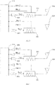
FIG. 1 is a schematic view of a first type of RF module provided by an exemplary embodiment of the present disclosure. -
FIG. 2 is a schematic view of a second type of RF module provided by an exemplary embodiment of the present disclosure. -
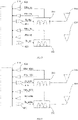
FIG. 3 is a schematic view of a third type of RF module provided by an exemplary embodiment of the present disclosure. -
FIG. 4 is a schematic view of a fourth type of RF module provided by an exemplary embodiment of the present disclosure. -
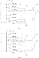
FIG. 5 is a schematic view of a fifth type of RF module provided by an exemplary embodiment of the present disclosure. -
FIG. 6 is a schematic view of a sixth type of RF module provided by an exemplary embodiment of the present disclosure. -
FIG. 7 is a schematic view of a seventh type of RF module provided by an exemplary embodiment of the present disclosure. -
FIG. 8 is a schematic view of an eighth type of RF module provided by an exemplary embodiment of the present disclosure. -
FIG. 9 is a schematic view of a ninth type of RF module provided by an exemplary embodiment of the present disclosure. -
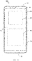
FIG. 10 is a schematic view of an electronic device provided by an exemplary embodiment of the present disclosure. - In the drawings: 110-RF transceiver module; 210-first triplexer; 220-second triplexer; 310-first antenna; 320-second antenna; 410-first amplifier circuit; 420-second amplifier circuit; 430-third amplifier circuit;
100-electronic device; 10-display screen; 11-display area; 12-non-display area; 20-frame; 30-motherboard; 40-battery; 50-rear cover. - Exemplary embodiments will now be described more comprehensively with reference to the accompanying drawings. However, the exemplary embodiments can be implemented in various forms, and should not be construed as being limited to the embodiments set forth herein; on the contrary, these embodiments are provided so that the present invention will be comprehensive and complete, and the concept of the exemplary embodiments is comprehensively conveyed to those skilled in the art. The same reference numerals in the figures represent the same or similar structures, and thus their detailed descriptions will be omitted.
- In an exemplary embodiment, a RF module is first provided. The RF module may be used in the electronic devices such as the mobile phones, the tablet computers, electronic readers, smart televisions, wearable terminals, vehicular computers, and so on. As shown in
FIG. 1 , the RF module includes aRF transceiver module 110, afirst antenna 310, afirst triplexer 210, asecond antenna 320, and asecond triplexer 220. TheRF transceiver module 110 is configured to transmit and receive RF signals. Thefirst antenna 310 is configured to transmit a first transmission signal, receive a first main reception signal, and receive a second diversity reception signal. A first terminal of thefirst triplexer 210 is connected to theRF transceiver module 110, and a second terminal of thefirst triplexer 210 is connected to thefirst antenna 310. Thefirst triplexer 210 is configured to isolate the first transmission signal, the first main reception signal, and the second diversity reception signal. Thesecond antenna 320 is configured to transmit a second transmission signal, receive a second main reception signal, and receive a first diversity reception signal. A frequency band of the first transmission signal is different from a frequency band of the second transmission signal. A first terminal of thesecond triplexer 220 is connected to theRF transceiver module 110, and a second terminal of thesecond triplexer 220 is connected to thesecond antenna 320. Thesecond triplexer 220 is configured to isolate the second transmission signal, the second main reception signal, and the first diversity reception signal. - In some embodiments, the first transmission signal is an uplink signal. The first main reception signal and the first diversity reception signal are downlink signals received based on the first transmission signal. The second transmission signal is an uplink signal. The second main reception signal and the second diversity reception signal are downlink signals received based on the second transmission signal.
- According to the RF module provided in some embodiments of the present disclosure, the
first antenna 310 is configured to transmit the first transmission signal, receive the first main reception signal, and receive the second diversity reception signal; and thesecond antenna 320 is configured to transmit the second transmission signal, receive the second main reception signal, and receive the first diversity reception signal. In this way, an occurrence of an additional antenna required to be arranged separately for receiving the first diversity reception signal and the second diversity reception signal may be reduced. The number of the antennas may be reduced, such that the problem of the difficulty of arranging the antennas in the electronic devices resulting from more antennas in the electronic devices may be solved at least to a certain extent. As a result, spaces of the electronic devices may be saved effectively. In addition, the number of RF channels may be reduced by virtue of adopting triplexers, such that a space of a motherboard may be saved. - As shown in
FIG. 2 , in some embodiments, the first terminal of thefirst triplexer 210 includes a first sub-terminal, a second sub-terminal, and a third sub-terminal. The first sub-terminal may be connected to theRF transceiver module 110 and configured to transmit the first transmission signal. The second sub-terminal may be connected to theRF transceiver module 110 and configured to transmit the first main reception signal. The third sub-terminal may be connected to theRF transceiver module 110 and configured to transmit the second diversity reception signal. After receiving a signal, thefirst antenna 310 may be configured to transmit a received signal to the second terminal of thefirst triplexer 210. Thefirst triplexer 210 may be configured to choose different sub-terminals based on types of received signals to output the received signals. For example, in response to the received signal being the first main reception signal, the received signal may be transmitted to the second sub-terminal, and finally output to theRF transceiver module 110. In response to the received signal being the second diversity reception signal, the received signal may be transmitted to the third sub-terminal, and finally output to theRF transceiver module 110. - As shown in
FIG. 3 , in the present embodiments, the RF module further includes afirst amplifier circuit 410. A first terminal of thefirst amplifier circuit 410 is connected to theRF transceiver module 110. A second terminal of thefirst amplifier circuit 410 is connected to the first sub-terminal of thefirst triplexer 210. Thefirst amplifier circuit 410 is configured to amplify the first transmission signal. Thefirst amplifier circuit 410 may include a power amplifier. - In some embodiments, the first terminal of the
second triplexer 220 includes a first sub-terminal, a second sub-terminal, and a third sub-terminal. The first sub-terminal may be connected to theRF transceiver module 110 and configured to transmit the second transmission signal. The second sub-terminal may be connected to theRF transceiver module 110 and configured to transmit the second main reception signal. The third sub-terminal may be connected to theRF transceiver module 110 and configured to transmit the second diversity reception signal. After receiving the signal, thesecond antenna 320 may be configured to transmit the received signal to the second terminal of thesecond triplexer 220. Thesecond triplexer 220 may be configured to choose different sub-terminals based on the types of the received signals to output the received signals. For example, in response to the received signal being the second main reception signal, the received signal may be transmitted to the second sub-terminal, and finally output to theRF transceiver module 110. In response to the received signal being the first diversity reception signal, the received signal may be transmitted to the third sub-terminal, and finally output to theRF transceiver module 110. - In the present embodiments, the RF module further includes a
second amplifier circuit 420. A first terminal of thesecond amplifier circuit 420 is connected to theRF transceiver module 110. A second terminal of thesecond amplifier circuit 420 is connected to the first sub-terminal of thesecond triplexer 220. Thesecond amplifier circuit 420 is configured to amplify the second transmission signal. Thesecond amplifier circuit 420 may include the power amplifier. - The
RF transceiver module 110 may include a first transmission unit, a second transmission unit, a first main reception unit, a second main reception unit, a first diversity reception unit, and a second diversity reception unit. The first transmission unit is connected to thefirst amplifier circuit 410 and configured to output the first transmission signal. The second transmission unit is connected to thesecond amplifier circuit 420 and configured to output the second transmission signal. The first main reception unit is connected to the second sub-terminal of thefirst triplexer 210 and configured to receive the first main reception signal. The second main reception unit is connected to the second sub-terminal of thesecond triplexer 220 and configured to receive the second main reception signal. The first diversity reception unit is connected to the third sub-terminal of thesecond triplexer 220 and configured to receive the first diversity reception signal. The second diversity reception unit is connected to the third sub-terminal of thefirst triplexer 210 and configured to receive the second diversity reception signal. - Further, the RF module may include multiple
third amplifier circuits 430. A corresponding one of thethird amplifier circuits 430 is arranged between the second sub-terminal of thefirst triplexer 210 and theRF transceiver module 110, between the third sub-terminal of thefirst triplexer 210 and theRF transceiver module 110, between the second sub-terminal of thesecond triplexer 220 and theRF transceiver module 110, and between the third sub-terminal of thesecond triplexer 220 and theRF transceiver module 110. - As shown in
FIG. 4 , onethird amplifier circuit 430 is connected to the second sub-terminal of thefirst triplexer 210 and the first main reception unit, and configured to amplify the first main reception signal. Anotherthird amplifier circuit 430 is connected to the third sub-terminal of thefirst triplexer 210 and the second diversity reception unit, and configured to amplify the second diversity reception signal. A yetthird amplifier circuit 430 is connected to the second sub-terminal of thesecond triplexer 220 and the second main reception unit, and configured to amplify the second main reception signal. A yetthird amplifier circuit 430 is connected to the third sub-terminal of thesecond triplexer 220 and the first diversity reception unit, and configured to amplify the first diversity reception signal. - In some embodiments, the
RF transceiver module 110 may be a RF transceiver, thethird amplifier circuit 430 may be arranged in theRF transceiver module 110 or outside theRF transceiver module 110. When thethird amplifying circuit 430 is arranged outside theRF transceiver module 110, thethird amplifying circuit 430 may be a low-noise amplifier (LNA). - In an embodiment, as shown in
FIG. 5 , the first transmission signal (Tx_Bx) may be a 4G LTE (Long Term Evolution) low-frequency signal, and the second transmission signal (Tx_ny) may be a 5G NR (5G new radio) low-frequency signal. Correspondingly, the first main reception signal (PRx_Bx) and the first diversity reception signal (DRx_Bx) may be LTE low-frequency signals. The second main reception signal (PRx_ny) and the second diversity reception signal (DRx_ny) may be 5G NR low-frequency signals. - In some embodiments, as shown in
FIG. 6 , a frequency band of the first transmission signal, a frequency band of the first main reception signal, and a frequency band of the first diversity reception signal are B20 respectively. A frequency band of the second transmission signal, a frequency band of the second main reception signal, and a frequency band of the second diversity reception signal are n28a respectively. - In some embodiments, an uplink frequency of a B20 frequency band is 832MHz-862MHz, and a downlink frequency of the B20 frequency band is 791MHz-821MHz. That is, a frequency of the first transmission signal is 832MHz-862MHz, and a frequency of the first main reception signal and a frequency of the first diversity reception signal are 791 MHz- 821MHz. An uplink frequency of an n28a frequency band is 703MHz-733MHz, and a downlink frequency of the n28a frequency band is 758MHz-788MHz. That is, a frequency of the second transmission signal is 703MHz-733MHz, and a frequency of the second main reception signal and a frequency of the second diversity reception signal are 758MHz-788MHz.
- In other embodiments, the frequency band of the first transmission signal, the frequency band of the first main reception signal, and the frequency band of the first diversity reception signal are B28a respectively. The frequency band of the second transmission signal, the frequency band of the second main reception signal, and the frequency band of the second diversity reception signal are n20 respectively.
- In some embodiments, an uplink frequency of a B28a frequency band is 703MHz-733MHz, and a downlink frequency of the B28a frequency band is 758MHz-788MHz. That is, the frequency of the first transmission signal is 703MHz-733MHz, and the frequency of the first main reception signal and the frequency of the first diversity reception signal are 758MHz-788MHz. An uplink frequency of an n20 frequency band is 832MHz-862MHz, and a downlink frequency of the n20 frequency band is 791 MHz-821MHz. That is, the frequency of the second transmission signal is 832MHz-862MHz, and the frequency of the second main reception signal and the frequency of the second diversity reception signal are 791 MHz-821MHz.
- In other embodiments, as shown in
FIG. 7 , the frequency band of the first main reception signal, and the frequency band of the first diversity reception signal are B20 respectively. The frequency band of the second transmission signal, the frequency band of the second main reception signal, and the frequency band of the second diversity reception signal are n8 respectively. - In some embodiments, the uplink frequency of the B20 frequency band is 832MHz-862MHz, and the downlink frequency of the B20 frequency band is 791MHz-821MHz. That is, the frequency of the first transmission signal is 832MHz-862MHz, and the frequency of the first main reception signal and the frequency of the first diversity reception signal are 791MHz-821MHz. An uplink frequency of an n8 frequency band is 880MHz-915MHz, and a downlink frequency of the n8 frequency band is 925MHz-960MHz. That is, the frequency of the second transmission signal is 880MHz-915MHz, and the frequency of the second main reception signal and the frequency of the second diversity reception signal are 925MHz-960MHz.
- In other embodiments, the frequency band of the first transmission signal, the frequency band of the first main reception signal, and the frequency band of the first diversity reception signal are B8 respectively. The frequency band of the second transmission signal, the frequency band of the second main reception signal, and the frequency band of the second diversity reception signal are n20 respectively.
- In some embodiments, an uplink frequency of a B8 frequency band is 880MHz-915MHz, and a downlink frequency of the B8 frequency band is 925MHz- 960MHz. That is, the frequency of the first transmission signal is 880MHz-915MHz, and the frequency of the first main reception signal and the frequency of the first diversity reception signal are 925MHz-960MHz. The uplink frequency of the B20 frequency band is 832MHz-862MHz, and the downlink frequency of the B20 frequency band is 791MHz-821MHz. That is, the frequency of the second transmission signal is 832MHz-862MHz, and the frequency of the second main reception signal and the frequency of the second diversity reception signal are 791MHz-821MHz.Of course, in actual applications, the frequency band of the first transmission signal, the frequency band of the first main reception signal, and the frequency band of the first diversity reception signal may be Bx respectively. The frequency band of the second transmission signal, the frequency band of the second main reception signal, and the frequency band of the second diversity reception signal may be other frequency bands ny respectively. No specific limitations are made in the embodiments of the present disclosure.
- A solution of two antennas are provided in the present disclosure to fully decouple two frequency-band antennas of a combination of a FDD low frequency and a low frequency EN-DC (E-UTRA and New radio Dual Connectivity, a dual connection of 4G wireless access network and 5G NR), which may achieve a lower cost. In this way, after low frequency bands are disassembled, an occurrence of a problem that a low frequency on the mobile phone is difficult to achieve a wide frequency band may be reduced.
- In some embodiments, as shown in
FIG. 8 , the first transmission signal (Tx_Bx) may be a LTE low-frequency signal, and the second transmission signal (Tx_By) may be a LTE low-frequency signal. Correspondingly, the first main reception signal (PRx_Bx) and the first diversity reception signal (DRx_Bx) may be LTE low-frequency signals. The second main reception signal (PRx_By) and the second diversity reception signal (DRx_By) may be the LTE low-frequency signals. - In some embodiments, the frequency band of the first transmission signal, the frequency band of the first main reception signal, and the frequency band of the first diversity reception signal are B20 respectively. The frequency band of the second transmission signal, the frequency band of the second main reception signal, and the frequency band of the second diversity reception signal are B28a respectively.
- In some embodiments, the uplink frequency of the B20 frequency band is 832MHz-862MHz, and the downlink frequency of the B20 frequency band is 791MHz-821MHz. That is, the frequency of the first transmission signal is 832MHz-862MHz, and the frequency of the first main reception signal and the frequency of the first diversity reception signal are 791MHz-821MHz. The uplink frequency of the B28a frequency band is 703MHz-733MHz, the downlink frequency of the B28a frequency band is 758MHz-788MHz. That is, the frequency of the second transmission signal is 703MHz-733MHz, and the frequency of the second main reception signal and the frequency of the second diversity reception signal are 758MHz-788MHz.
- In other embodiments, the frequency band of the first transmission signal, the frequency band of the first main reception signal, and the frequency band of the first diversity reception signal are B20 respectively. The frequency band of the second transmission signal, the frequency band of the second main reception signal, and the frequency band of the second diversity reception signal are B8 respectively.
- In some embodiments, the uplink frequency of the B20 frequency band is 832MHz-862MHz, and the downlink frequency of the B20 frequency band is 791MHz-821MHz. That is, the frequency of the first transmission signal is 832MHz-862MHz, and the frequency of the first main reception signal and the frequency of the first diversity reception signal are 791MHz-821MHz. The uplink frequency of the B8 frequency band is 880MHz-915MHz, and the downlink frequency of the B8 frequency band is 925MHz- 960MHz. That is, the frequency of the second transmission signal is 880MHz-915MHz, and the frequency of the second main reception signal and the frequency of the second diversity reception signal are 925MHz-960MHz.
- Of course, in the actual applications, the frequency band of the first transmission signal, the frequency band of the first main reception signal, and the frequency band of the first diversity reception signal may be other frequency bands Bx respectively. The frequency band of the second transmission signal, the frequency band of the second main reception signal, and the frequency band of the second diversity reception signal may be the other frequency bands By respectively. No specific limitations are made in the embodiments of the present disclosure.
- In an embodiment, as shown in
FIG. 9 , the first transmission signal (Tx_nx) may be a 5G NR low-frequency signal, and the second transmission signal (Tx_ny) may be the 5G NR low-frequency signal. Correspondingly, the first main reception signal (PRx_nx) and the first diversity reception signal (DRx_nx) may be 5G NR low-frequency signals. The second main reception signal (PRx_ny) and the second diversity reception signal (DRx_ny) may be the 5G NR low-frequency signals. - In some embodiments, the frequency band of the first transmission signal, the frequency band of the first main reception signal, and the frequency band of the first diversity reception signal are n20 respectively. The frequency band of the second transmission signal, the frequency band of the second main reception signal, and the frequency band of the second diversity reception signal are n28a respectively.
- In some embodiments, the uplink frequency of the n20 frequency band is 832MHz-862MHz, and the downlink frequency of the n20 frequency band is 791MHz-821MHz. That is, the frequency of the first transmission signal is 832MHz-862MHz, and the frequency of the first main reception signal and the frequency of the first diversity reception signal are 791MHz-821MHz. The uplink frequency of the n28a frequency band is 703MHz-733MHz, and the downlink frequency of the n28a frequency band is 758MHz-788MHz. That is, the frequency of the second transmission signal is 703MHz-733MHz, and the frequency of the second main reception signal and the frequency of the second diversity reception signal are 758MHz-788MHz.
- In other embodiments, the frequency band of the first transmission signal, the frequency band of the first main reception signal, and the frequency band of the first diversity reception signal are n20 respectively. The frequency band of the second transmission signal, the frequency band of the second main reception signal, and the frequency band of the second diversity reception signal are n8 respectively.
- In some embodiments, the uplink frequency of the n20 frequency band is 832MHz-862MHz, and the downlink frequency of the n20 frequency band is 791MHz-821MHz. That is, the frequency of the first transmission signal is 832MHz-862MHz, and the frequency of the first main reception signal and the frequency of the first diversity reception signal are 791MHz-821MHz. The uplink frequency of the n8 frequency band is 880MHz-915MHz, and the downlink frequency of the n8 frequency band is 925MHz-960MHz. That is, the frequency of the second transmission signal is 880MHz-915MHz, and the frequency of the second main reception signal and the frequency of the second diversity reception signal are 925MHz-960MHz.
- Of course, in the actual applications, the frequency band of the first transmission signal, the frequency band of the first main reception signal, and the frequency band of the first diversity reception signal may be other frequency bands nx respectively. The frequency band of the second transmission signal, the frequency band of the second main reception signal, and the frequency band of the second diversity reception signal may be the other frequency bands ny respectively. No specific limitations are made in the embodiments of the present disclosure.
- According to the RF module provided in some embodiments of the present disclosure, the
first antenna 310 is configured to transmit the first transmission signal, receive the first main reception signal, and receive the second diversity reception signal; and thesecond antenna 320 is configured to transmit the second transmission signal, receive the second main reception signal, and receive the first diversity reception signal. In this way, the occurrence of the additional antenna required to be arranged separately for receiving the first diversity reception signal and the second diversity reception signal may be reduced. The number of the antennas may be reduced, such that the problem of the difficulty of arranging the antennas in the electronic devices resulting from more antennas in the electronic devices may be solved at least to a certain extent. As a result, the spaces of the electronic devices may be saved effectively. In addition, the number of the RF channels may be reduced by virtue of adopting the triplexers, such that the space of the motherboard may be saved. - An electronic device is further provided in some embodiments of the present disclosure and includes the RF module described above.
- As shown in
FIG. 10 , theelectronic device 100 may further include adisplay screen 10, aframe 20, amotherboard 30, abattery 40 and arear cover 50. In some embodiments, thedisplay screen 10 is installed in theframe 20 to assemble a display surface of theelectronic device 100. Thedisplay screen 10 may serve as a front housing of theelectronic device 100. Therear cover 50 is pasted on theframe 20 by a double-sided tape. An accommodation space is defined by thedisplay screen 10, theframe 20, and therear cover 50 to accommodate other electronic components or functional modules of theelectronic device 100. In addition, the display surface formed by thedisplay screen 10 is configured to display information such as images and texts. Thedisplay screen 10 may be a liquid crystal display (LCD) or an organic light-emitting diode (OLED) type display screen, and the like. - A glass cover plate may be arranged on the
display screen 10. The glass cover plate may cover thedisplay screen 10 to protect thedisplay screen 10 and reduce a possibility of thedisplay screen 10 being scratched or damaged by water. - The
display screen 10 may include adisplay area 11 and anon-display area 12. Thedisplay area 11 is configured to perform a display function of thedisplay screen 10 for displaying the information such as the images and the texts. Thenon-display area 12 is configured not to display information and to be arranged with a functional module such as a camera, a receiver, and a proximity sensor. In some embodiments, thenon-display area 12 may include at least one area located at an upper portion or a lower portion of thedisplay area 11. - The
display screen 10 may be a full screen. In this case, thedisplay screen 10 may display the information in the full screen, such that theelectronic device 100 may have a larger screen ratio. Thedisplay screen 10 includes only thedisplay area 11 rather than thenon-display area 12. In this case, the functional module such as the camera and the proximity sensor in theelectronic device 100 may be hidden under thedisplay screen 10, and a fingerprint recognition module of theelectronic device 100 may be arranged on a rear surface of theelectronic device 100. - The
frame 20 may be a hollow frame structure. A material of theframe 20 may include a metal or a plastic. Themotherboard 30 is installed inside the accommodation space described above. For example, themotherboard 30 may be installed on theframe 20 and accommodated in the accommodation space with theframe 20. A ground point is arranged on themotherboard 30 to achieve a grounding of themotherboard 30. Themotherboard 30 may be integrated with one or more the functional module such as a motor, a microphone, a speaker, a receiver, a headphone interface, a universal serial bus interface (a USB interface), the camera, the proximity sensor, an ambient light sensor, a gyroscope, and a processor. In addition, thedisplay screen 10 may be electrically connected to themotherboard 30. - A display-controlling circuit may be arranged on the
motherboard 30 and configured to output an electrical signal for controlling thedisplay screen 10 to display the information. - The
battery 40 is installed inside the accommodation space. For example, thebattery 40 may be mounted on theframe 20 and accommodated in the accommodation space with theframe 20. Thebattery 40 may be electrically connected to themotherboard 30 for supplying power to theelectronic device 100. In some embodiments, a power management circuit may be arranged on themotherboard 30 and configured to distribute a voltage supplied by thebattery 40 to each of electronic components in theelectronic device 100. - The
rear cover 50 is configured to define an outer contour of theelectronic device 100. Therear cover 50 may be integrally formed. During a process of forming therear cover 50, a structure such as a rear camera hole, a mounting hole for the fingerprint identification module, and the like, may be defined in therear cover 50. - The
RF transceiver module 110, thefirst triplexer 210, thesecond triplexer 220, thefirst amplifier circuit 410, thesecond amplifier circuit 420, thethird amplifier circuit 430, and other components in the RF module may be arranged on themotherboard 30. A grounding portion may also be arranged on themotherboard 30. Thefirst antenna 310 and thesecond antenna 320 may be connected to the grounding portion. - The
first antenna 310 and thesecond antenna 320 may be arranged on themotherboard 30, or theframe 20, or therear cover 50. When the antennas are arranged on theframe 20, theframe 20 may be a metal frame. The metal frame may be separated to multiple sections by insulators. When the antennas are arranged on therear cover 50, the rear cover may be a metal rear cover and separated to multiple sections. - The
first antenna 310 and thesecond antenna 320 may be dedicated antennas for low-frequency signals or antennas shared by the low-frequency signals and high-frequency signals. When thefirst antenna 310 and thesecond antenna 320 are the antennas shared by the low-frequency signals and high-frequency signals, a switching circuit may also be arranged on themotherboard 30 for switching the antennas to connect RF modules with different frequencies. - According to the electronic device provided in some embodiments of the present disclosure, the
first antenna 310 is configured to transmit the first transmission signal, receive the first main reception signal, and receive the second diversity reception signal; and thesecond antenna 320 is configured to transmit the second transmission signal, receive the second main reception signal, and receive the first diversity reception signal. In this way, the occurrence of the additional antenna required to be arranged separately for receiving the first diversity reception signal and the second diversity reception signal may be reduced. The number of the antennas may be reduced, such that the problem of the difficulty of arranging the antennas in the electronic devices resulting from more antennas in the electronic devices may be solved at least to a certain extent. As a result, the spaces of the electronic devices may be saved effectively. In addition, the number of the RF channels may be reduced by virtue of adopting the triplexers, such that the space of the motherboard may be saved. - After considering the specification and implementing solutions of the present disclosure, it is readily for those skilled in the art to obtain other embodiments of the present disclosure. The present disclosure is intended to cover any variations, applications, or adaptive changes of the present disclosure which follow general principles of the present disclosure and include common knowledge or techniques in the art not disclosed by the present disclosure. The specification and embodiments are only regarded to be exemplary. A true scope and a spirit of the present disclosure are indicated by the appended claims.
Claims (20)
- A radio frequency (RF) module, comprising:a RF transceiver module, configured to transmit and receive RF signals;a first antenna, configured to transmit a first transmission signal, receive a first main reception signal, and receive a second diversity reception signal;a first triplexer, comprising a first terminal connected to the RF transceiver module, and a second terminal connected to the first antenna, wherein the first triplexer is configured to isolate the first transmission signal, the first main reception signal, and the second diversity reception signal;a second antenna, configured to transmit a second transmission signal, receive a second main reception signal, and receive a first diversity reception signal; wherein a frequency band of the first transmission signal is different from a frequency band of the second transmission signal; anda second triplexer, comprising a first terminal connected to the RF transceiver module, and a second terminal connected to the second antenna, wherein the second triplexer is configured to isolate the second transmission signal, the second main reception signal, and the first diversity reception signal.
- The RF module according to claim 1, wherein the first terminal of the first triplexer comprises:a first sub-terminal, connected to the RF transceiver module and configured to transmit the first transmission signal;a second sub-terminal, connected to the RF transceiver module and configured to transmit the first main reception signal; anda third sub-terminal, connected to the RF transceiver module and configured to transmit the second diversity reception signal.
- The RF module according to claim 2, wherein the RF module further comprises:
a first amplifier circuit, comprising a first terminal connected to the RF transceiver module, and a second terminal connected to the first sub-terminal of the first triplexer, wherein the first amplifier circuit is configured to amplify the first transmission signal. - The RF module according to claim 2, wherein the first terminal of the second triplexer comprises:a first sub-terminal, connected to the RF transceiver module and configured to transmit the second transmission signal;a second sub-terminal, connected to the RF transceiver module and configured to transmit the second main reception signal; anda third sub-terminal, connected to the RF transceiver module and configured to transmit the second diversity reception signal.
- The RF module according to claim 4, wherein the RF module further comprises:
a second amplifier circuit, comprising a first terminal connected to the RF transceiver module, and a second terminal connected to the first sub-terminal of the second triplexer, wherein the second amplifier circuit is configured to amplify the second transmission signal. - The RF module according to claim 4, further comprising:
third amplifier circuits, wherein a corresponding one of the third amplifier circuits is arranged between the second sub-terminal of the first triplexer and the RF transceiver module, between the third sub-terminal of the first triplexer and the RF transceiver module, between the second sub-terminal of the second triplexer and the RF transceiver module, and between the third sub-terminal of the second triplexer and the RF transceiver module. - The RF module according to claim 1, wherein a frequency band of the first transmission signal, a frequency band of the first main reception signal, and a frequency band of the first diversity reception signal are 4G frequency bands; and a frequency band of the second transmission signal, a frequency band of the second main reception signal, and a frequency band of the second diversity reception signal are 5G frequency bands.
- The RF module according to claim 7, wherein the frequency band of the first transmission signal, the frequency band of the first main reception signal, and the frequency band of the first diversity reception signal are B20 respectively; and the frequency band of the second transmission signal, the frequency band of the second main reception signal, and the frequency band of the second diversity reception signal are n8 respectively.
- The RF module according to claim 7, wherein the frequency band of the first transmission signal, the frequency band of the first main reception signal, and the frequency band of the first diversity reception signal are B8 respectively; and the frequency band of the second transmission signal, the frequency band of the second main reception signal, and the frequency band of the second diversity reception signal are n20 respectively.
- The RF module according to claim 7, wherein the frequency band of the first transmission signal, the frequency band of the first main reception signal, and the frequency band of the first diversity reception signal are B20 respectively; and the frequency band of the second transmission signal, the frequency band of the second main reception signal, and the frequency band of the second diversity reception signal are n28a respectively.
- The RF module according to claim 7, wherein the frequency band of the first transmission signal, the frequency band of the first main reception signal, and the frequency band of the first diversity reception signal are B28a respectively; and the frequency band of the second transmission signal, the frequency band of the second main reception signal, and the frequency band of the second diversity reception signal are n20 respectively.
- The RF module according to claim 1, wherein a frequency band of the first transmission signal, a frequency band of the first main reception signal, and a frequency band of the first diversity reception signal are 4G frequency bands; and a frequency band of the second transmission signal, a frequency band of the second main reception signal, and a frequency band of the second diversity reception signal are the 4G frequency bands.
- The RF module according to claim 12, wherein the frequency band of the first transmission signal, the frequency band of the first main reception signal, and the frequency band of the first diversity reception signal are B20 respectively; and the frequency band of the second transmission signal, the frequency band of the second main reception signal, and the frequency band of the second diversity reception signal are B8 respectively.
- The RF module according to claim 12, wherein the frequency band of the first transmission signal, the frequency band of the first main reception signal, and the frequency band of the first diversity reception signal are B20 respectively; and the frequency band of the second transmission signal, the frequency band of the second main reception signal, and the frequency band of the second diversity reception signal are B28a respectively.
- The RF module according to claim 1, wherein The RF module according to claim 1, wherein a frequency band of the first transmission signal, a frequency band of the first main reception signal, and a frequency band of the first diversity reception signal are 5G frequency bands; and a frequency band of the second transmission signal, a frequency band of the second main reception signal, and a frequency band of the second diversity reception signal are the 5G frequency bands.
- The RF module according to claim 15, wherein the frequency band of the first transmission signal, the frequency band of the first main reception signal, and the frequency band of the first diversity reception signal are n20 respectively; and the frequency band of the second transmission signal, the frequency band of the second main reception signal, and the frequency band of the second diversity reception signal are n8 respectively.
- The RF module according to claim 15, wherein the frequency band of the first transmission signal, the frequency band of the first main reception signal, and the frequency band of the first diversity reception signal are n20 respectively; and the frequency band of the second transmission signal, the frequency band of the second main reception signal, and the frequency band of the second diversity reception signal are n28a respectively.
- An electronic device, wherein the electronic device comprises a RF module according to any one of claims 1-17.
- The electronic device according to claim 18, further comprising:
a motherboard, wherein the first triplexer and the second triplexer are arranged on the motherboard. - The electronic device according to claim 18, further comprising:a frame, comprising:a first metal branch; anda second metal branch;wherein the first metal branch is as a radiator of the first antenna, and the second metal branch is as a radiator of the second antenna.
Applications Claiming Priority (2)
| Application Number | Priority Date | Filing Date | Title |
|---|---|---|---|
| CN201911410335.XA CN111181606A (en) | 2019-12-31 | 2019-12-31 | RF modules and electronic equipment |
| PCT/CN2020/142140 WO2021136506A1 (en) | 2019-12-31 | 2020-12-31 | Radio frequency module and electronic device |
Publications (2)
| Publication Number | Publication Date |
|---|---|
| EP4072029A1 true EP4072029A1 (en) | 2022-10-12 |
| EP4072029A4 EP4072029A4 (en) | 2023-02-08 |
Family
ID=70649123
Family Applications (1)
| Application Number | Title | Priority Date | Filing Date |
|---|---|---|---|
| EP20910769.7A Pending EP4072029A4 (en) | 2019-12-31 | 2020-12-31 | RADIO FREQUENCY MODULE AND ELECTRONIC DEVICE |
Country Status (5)
| Country | Link |
|---|---|
| US (1) | US11990968B2 (en) |
| EP (1) | EP4072029A4 (en) |
| JP (1) | JP2023509041A (en) |
| CN (1) | CN111181606A (en) |
| WO (1) | WO2021136506A1 (en) |
Families Citing this family (7)
| Publication number | Priority date | Publication date | Assignee | Title |
|---|---|---|---|---|
| CN111181606A (en) | 2019-12-31 | 2020-05-19 | Oppo广东移动通信有限公司 | RF modules and electronic equipment |
| CN115956287B (en) * | 2020-08-27 | 2025-11-18 | 株式会社村田制作所 | High-frequency modules and communication devices |
| CN116097424B (en) * | 2020-09-24 | 2025-08-05 | 株式会社村田制作所 | High frequency module and communication device |
| US12407306B2 (en) * | 2021-08-04 | 2025-09-02 | Skyworks Solutions, Inc. | Radio frequency front end with integrated channel matching calibration |
| CN117155416A (en) * | 2022-05-24 | 2023-12-01 | 惠州Tcl移动通信有限公司 | An ENDC dual-connection radio frequency structure and mobile terminal |
| CN115765763A (en) * | 2022-11-16 | 2023-03-07 | 合肥龙旗智能科技有限公司 | A sending and receiving signal processing circuit, processing method and communication equipment |
| CN117220711A (en) * | 2023-10-27 | 2023-12-12 | 维沃移动通信有限公司 | RF architecture and electronic equipment |
Family Cites Families (38)
| Publication number | Priority date | Publication date | Assignee | Title |
|---|---|---|---|---|
| JP4428292B2 (en) * | 2005-05-27 | 2010-03-10 | Tdk株式会社 | Triplexer circuit |
| US8711038B2 (en) * | 2006-10-05 | 2014-04-29 | Her Majesty The Queen In Right Of Canada As Represented By The Minister Of Industry, Through The Communications Research Centre Canada | High-resolution ranging and location finding using multicarrier signals |
| DE102007019082B4 (en) * | 2007-04-23 | 2018-04-05 | Snaptrack Inc. | front end module |
| WO2009157357A1 (en) * | 2008-06-25 | 2009-12-30 | 日立金属株式会社 | High-frequency circuit, high-frequency component, and communication device |
| JP5236711B2 (en) * | 2010-09-30 | 2013-07-17 | 株式会社エヌ・ティ・ティ・ドコモ | Mobile communication terminal, multi-frequency simultaneous communication method |
| US9312888B2 (en) * | 2012-06-29 | 2016-04-12 | Qualcomm Incorporated | Antenna interface circuits for carrier aggregation on multiple antennas |
| US9467191B2 (en) * | 2012-11-12 | 2016-10-11 | Qualcomm Incorporated | Antenna interface circuits with quadplexers |
| US9722639B2 (en) * | 2013-05-01 | 2017-08-01 | Qorvo Us, Inc. | Carrier aggregation arrangements for mobile devices |
| CN103338054B (en) * | 2013-06-09 | 2017-11-28 | 华为终端(东莞)有限公司 | Multifrequency community antenna system, radio-frequency front-end and multi-band communication device |
| US9893709B2 (en) * | 2014-03-14 | 2018-02-13 | Qorvo Us, Inc. | RF triplexer architecture |
| US9900196B2 (en) * | 2014-11-26 | 2018-02-20 | Avago Technologies General Ip (Singapore) Pte. Ltd. | Switching diversity in scalable radio frequency communication system |
| US20160191107A1 (en) * | 2014-12-24 | 2016-06-30 | Rf Micro Devices, Inc. | Radio frequency front end circuitry for carrier aggregation |
| WO2016104234A1 (en) * | 2014-12-26 | 2016-06-30 | 株式会社村田製作所 | High-frequency front end circuit and communication device |
| US10707905B2 (en) * | 2015-06-23 | 2020-07-07 | Skyworks Solutions, Inc. | Wideband multiplexer for radio-frequency applications |
| KR20170022235A (en) * | 2015-08-19 | 2017-03-02 | (주)와이솔 | Filter Module For Carrier Aggregation and Electronic Apparatus Including The Same |
| CN105306112B (en) | 2015-09-30 | 2018-08-31 | 联想(北京)有限公司 | Diversity aerial system, electronic equipment and its control method |
| US10111115B2 (en) * | 2015-10-06 | 2018-10-23 | Skyworks Solutions, Inc. | Front end system with lossy transmission line between front end module and transceiver |
| US10616053B2 (en) * | 2015-12-04 | 2020-04-07 | Skyworks Solutions, Inc. | Multi-stage reconfigurable triplexer |
| CN106911350B (en) * | 2015-12-22 | 2019-06-25 | 华硕电脑股份有限公司 | wireless communication device |
| US10432274B2 (en) * | 2016-01-04 | 2019-10-01 | Skyworks Solutions, Inc. | Wireless communication system with simplex front-end |
| JP2017200183A (en) * | 2016-04-29 | 2017-11-02 | スカイワークス ソリューションズ, インコーポレイテッドSkyworks Solutions, Inc. | Shielded diversity receiver module |
| US9998097B2 (en) * | 2016-07-15 | 2018-06-12 | Murata Manufacturing Co., Ltd. | Radio-frequency front-end circuit and communication device |
| US10075199B2 (en) * | 2016-07-17 | 2018-09-11 | Skyworks Solutions, Inc. | Uplink carrier aggregation front-end architecture that supports simultaneous MIMO |
| TWI732034B (en) * | 2016-08-29 | 2021-07-01 | 美商天工方案公司 | Multi-standard radio switchable multiplexer |
| US10716157B2 (en) * | 2017-02-09 | 2020-07-14 | Apple Inc. | 5G/LTE dual connectivity |
| CN106921405A (en) * | 2017-02-28 | 2017-07-04 | 维沃移动通信有限公司 | A kind of radio frequency front-end device |
| US10659121B2 (en) * | 2017-03-15 | 2020-05-19 | Skyworks Solutions, Inc. | Apparatus and methods for radio frequency front-ends |
| JP6848052B2 (en) * | 2017-09-11 | 2021-03-24 | エルジー エレクトロニクス インコーポレイティド | A terminal that supports a dual connection between E-UTRA and NR A terminal that implements a method and method of transmitting and receiving signals |
| US10727894B2 (en) * | 2018-04-30 | 2020-07-28 | Skyworks Solutions, Inc. | Front end systems with switched termination for enhanced intermodulation distortion performance |
| WO2019216577A1 (en) * | 2018-05-11 | 2019-11-14 | 엘지전자 주식회사 | Method for transmitting and receiving signal by terminal supporting dual connectivity between e-utra and nr and terminal for performing same method |
| US10505602B1 (en) * | 2018-07-02 | 2019-12-10 | Phazr, Inc. | Methods and systems for spectrum aggregation in wireless communication |
| US20200076488A1 (en) * | 2018-08-30 | 2020-03-05 | Skyworks Solutions, Inc. | Beamforming communication systems with sensor aided beam management |
| CN210958415U (en) * | 2019-07-17 | 2020-07-07 | 华为技术有限公司 | Center, battery cover and electronic equipment |
| US11785659B2 (en) * | 2019-10-04 | 2023-10-10 | Lg Electronics Inc. | Method for applying MSD and apparatus thereof |
| CN111181606A (en) * | 2019-12-31 | 2020-05-19 | Oppo广东移动通信有限公司 | RF modules and electronic equipment |
| CN111294081B (en) * | 2020-01-22 | 2022-01-11 | Oppo广东移动通信有限公司 | Radio frequency system and electronic equipment |
| CN113746496B (en) * | 2020-03-03 | 2022-07-08 | Oppo广东移动通信有限公司 | Radio frequency system and electronic equipment |
| CN114978201B (en) * | 2021-02-25 | 2024-02-02 | Oppo广东移动通信有限公司 | RF front-end modules and electronic equipment |
-
2019
- 2019-12-31 CN CN201911410335.XA patent/CN111181606A/en active Pending
-
2020
- 2020-12-31 JP JP2022540592A patent/JP2023509041A/en active Pending
- 2020-12-31 EP EP20910769.7A patent/EP4072029A4/en active Pending
- 2020-12-31 WO PCT/CN2020/142140 patent/WO2021136506A1/en not_active Ceased
-
2022
- 2022-06-28 US US17/851,950 patent/US11990968B2/en active Active
Also Published As
| Publication number | Publication date |
|---|---|
| US11990968B2 (en) | 2024-05-21 |
| JP2023509041A (en) | 2023-03-06 |
| EP4072029A4 (en) | 2023-02-08 |
| US20220329299A1 (en) | 2022-10-13 |
| WO2021136506A1 (en) | 2021-07-08 |
| CN111181606A (en) | 2020-05-19 |
Similar Documents
| Publication | Publication Date | Title |
|---|---|---|
| US11664831B2 (en) | Radio frequency assembly and electronic device | |
| US11990968B2 (en) | Radio frequency module and electronic device | |
| US12334644B2 (en) | Antenna apparatus and electronic device | |
| US9178268B2 (en) | Antennas integrated with speakers and methods for suppressing cavity modes | |
| CN110635821A (en) | RF circuits and electronic equipment | |
| US20240022282A1 (en) | Radio frequency front-end module, antenna system, and electronic device | |
| CN108880571B (en) | RF circuits and electronic equipment | |
| EP4024609B1 (en) | Antenna apparatus and electronic device | |
| CN108448228B (en) | Antenna components and electronic equipment | |
| US12101113B2 (en) | Radio frequency module, control method, and electronic device | |
| CN212874748U (en) | Electronic device | |
| CN108768432B (en) | Radio frequency circuit and electronic equipment | |
| CN112103624A (en) | Antenna device and electronic apparatus | |
| CN109951204B (en) | RF circuits, antenna devices and electronic equipment | |
| CN214378862U (en) | Antenna systems and electronic equipment | |
| CN109951209B (en) | RF circuits, antenna devices and electronic equipment | |
| CN109951203B (en) | RF circuits, antenna devices and electronic equipment | |
| US20230403046A1 (en) | Millimeter wave communication apparatus | |
| CN115118302B (en) | Antenna device and electronic equipment | |
| CN212571326U (en) | Antenna assembly and electronic equipment | |
| CN109951208B (en) | RF circuits, antenna devices and electronic equipment |
Legal Events
| Date | Code | Title | Description |
|---|---|---|---|
| STAA | Information on the status of an ep patent application or granted ep patent |
Free format text: STATUS: THE INTERNATIONAL PUBLICATION HAS BEEN MADE |
|
| PUAI | Public reference made under article 153(3) epc to a published international application that has entered the european phase |
Free format text: ORIGINAL CODE: 0009012 |
|
| STAA | Information on the status of an ep patent application or granted ep patent |
Free format text: STATUS: REQUEST FOR EXAMINATION WAS MADE |
|
| 17P | Request for examination filed |
Effective date: 20220705 |
|
| AK | Designated contracting states |
Kind code of ref document: A1 Designated state(s): AL AT BE BG CH CY CZ DE DK EE ES FI FR GB GR HR HU IE IS IT LI LT LU LV MC MK MT NL NO PL PT RO RS SE SI SK SM TR |
|
| A4 | Supplementary search report drawn up and despatched |
Effective date: 20230109 |
|
| RIC1 | Information provided on ipc code assigned before grant |
Ipc: H04B 7/02 19680901ALN20230102BHEP Ipc: H04B 1/00 19680901ALI20230102BHEP Ipc: H04B 1/40 19680901AFI20230102BHEP |
|
| DAV | Request for validation of the european patent (deleted) | ||
| DAX | Request for extension of the european patent (deleted) | ||
| STAA | Information on the status of an ep patent application or granted ep patent |
Free format text: STATUS: EXAMINATION IS IN PROGRESS |
|
| 17Q | First examination report despatched |
Effective date: 20250227 |
|
| RAP1 | Party data changed (applicant data changed or rights of an application transferred) |
Owner name: NOKIA TECHNOLOGIES OY |