EP4071953A1 - Battery pack and electrical apparatus using same - Google Patents
Battery pack and electrical apparatus using same Download PDFInfo
- Publication number
- EP4071953A1 EP4071953A1 EP21782179.2A EP21782179A EP4071953A1 EP 4071953 A1 EP4071953 A1 EP 4071953A1 EP 21782179 A EP21782179 A EP 21782179A EP 4071953 A1 EP4071953 A1 EP 4071953A1
- Authority
- EP
- European Patent Office
- Prior art keywords
- battery pack
- control unit
- terminal
- cell
- battery
- Prior art date
- Legal status (The legal status is an assumption and is not a legal conclusion. Google has not performed a legal analysis and makes no representation as to the accuracy of the status listed.)
- Pending
Links
Images





Classifications
-
- H—ELECTRICITY
- H01—ELECTRIC ELEMENTS
- H01M—PROCESSES OR MEANS, e.g. BATTERIES, FOR THE DIRECT CONVERSION OF CHEMICAL ENERGY INTO ELECTRICAL ENERGY
- H01M10/00—Secondary cells; Manufacture thereof
- H01M10/42—Methods or arrangements for servicing or maintenance of secondary cells or secondary half-cells
- H01M10/48—Accumulators combined with arrangements for measuring, testing or indicating the condition of cells, e.g. the level or density of the electrolyte
- H01M10/482—Accumulators combined with arrangements for measuring, testing or indicating the condition of cells, e.g. the level or density of the electrolyte for several batteries or cells simultaneously or sequentially
-
- H—ELECTRICITY
- H01—ELECTRIC ELEMENTS
- H01M—PROCESSES OR MEANS, e.g. BATTERIES, FOR THE DIRECT CONVERSION OF CHEMICAL ENERGY INTO ELECTRICAL ENERGY
- H01M10/00—Secondary cells; Manufacture thereof
- H01M10/42—Methods or arrangements for servicing or maintenance of secondary cells or secondary half-cells
- H01M10/425—Structural combination with electronic components, e.g. electronic circuits integrated to the outside of the casing
-
- H—ELECTRICITY
- H01—ELECTRIC ELEMENTS
- H01M—PROCESSES OR MEANS, e.g. BATTERIES, FOR THE DIRECT CONVERSION OF CHEMICAL ENERGY INTO ELECTRICAL ENERGY
- H01M10/00—Secondary cells; Manufacture thereof
- H01M10/42—Methods or arrangements for servicing or maintenance of secondary cells or secondary half-cells
- H01M10/48—Accumulators combined with arrangements for measuring, testing or indicating the condition of cells, e.g. the level or density of the electrolyte
-
- H—ELECTRICITY
- H01—ELECTRIC ELEMENTS
- H01M—PROCESSES OR MEANS, e.g. BATTERIES, FOR THE DIRECT CONVERSION OF CHEMICAL ENERGY INTO ELECTRICAL ENERGY
- H01M10/00—Secondary cells; Manufacture thereof
- H01M10/42—Methods or arrangements for servicing or maintenance of secondary cells or secondary half-cells
- H01M10/48—Accumulators combined with arrangements for measuring, testing or indicating the condition of cells, e.g. the level or density of the electrolyte
- H01M10/486—Accumulators combined with arrangements for measuring, testing or indicating the condition of cells, e.g. the level or density of the electrolyte for measuring temperature
-
- H—ELECTRICITY
- H01—ELECTRIC ELEMENTS
- H01M—PROCESSES OR MEANS, e.g. BATTERIES, FOR THE DIRECT CONVERSION OF CHEMICAL ENERGY INTO ELECTRICAL ENERGY
- H01M50/00—Constructional details or processes of manufacture of the non-active parts of electrochemical cells other than fuel cells, e.g. hybrid cells
- H01M50/20—Mountings; Secondary casings or frames; Racks, modules or packs; Suspension devices; Shock absorbers; Transport or carrying devices; Holders
- H01M50/204—Racks, modules or packs for multiple batteries or multiple cells
-
- H—ELECTRICITY
- H01—ELECTRIC ELEMENTS
- H01M—PROCESSES OR MEANS, e.g. BATTERIES, FOR THE DIRECT CONVERSION OF CHEMICAL ENERGY INTO ELECTRICAL ENERGY
- H01M50/00—Constructional details or processes of manufacture of the non-active parts of electrochemical cells other than fuel cells, e.g. hybrid cells
- H01M50/20—Mountings; Secondary casings or frames; Racks, modules or packs; Suspension devices; Shock absorbers; Transport or carrying devices; Holders
- H01M50/247—Mountings; Secondary casings or frames; Racks, modules or packs; Suspension devices; Shock absorbers; Transport or carrying devices; Holders specially adapted for portable devices, e.g. mobile phones, computers, hand tools or pacemakers
-
- H—ELECTRICITY
- H01—ELECTRIC ELEMENTS
- H01M—PROCESSES OR MEANS, e.g. BATTERIES, FOR THE DIRECT CONVERSION OF CHEMICAL ENERGY INTO ELECTRICAL ENERGY
- H01M50/00—Constructional details or processes of manufacture of the non-active parts of electrochemical cells other than fuel cells, e.g. hybrid cells
- H01M50/50—Current conducting connections for cells or batteries
- H01M50/572—Means for preventing undesired use or discharge
- H01M50/574—Devices or arrangements for the interruption of current
- H01M50/581—Devices or arrangements for the interruption of current in response to temperature
-
- H—ELECTRICITY
- H01—ELECTRIC ELEMENTS
- H01M—PROCESSES OR MEANS, e.g. BATTERIES, FOR THE DIRECT CONVERSION OF CHEMICAL ENERGY INTO ELECTRICAL ENERGY
- H01M50/00—Constructional details or processes of manufacture of the non-active parts of electrochemical cells other than fuel cells, e.g. hybrid cells
- H01M50/50—Current conducting connections for cells or batteries
- H01M50/572—Means for preventing undesired use or discharge
- H01M50/574—Devices or arrangements for the interruption of current
- H01M50/583—Devices or arrangements for the interruption of current in response to current, e.g. fuses
-
- H—ELECTRICITY
- H02—GENERATION; CONVERSION OR DISTRIBUTION OF ELECTRIC POWER
- H02J—ELECTRIC POWER NETWORKS; CIRCUIT ARRANGEMENTS OR SYSTEMS FOR SUPPLYING OR DISTRIBUTING ELECTRIC POWER; SYSTEMS FOR STORING ELECTRIC ENERGY
- H02J7/00—Circuit arrangements for charging or discharging batteries or for supplying loads from batteries
- H02J7/40—Circuit arrangements for charging or discharging batteries or for supplying loads from batteries characterised by the exchange of charge or discharge related data
- H02J7/44—Circuit arrangements for charging or discharging batteries or for supplying loads from batteries characterised by the exchange of charge or discharge related data between battery management systems and power sources
-
- H—ELECTRICITY
- H02—GENERATION; CONVERSION OR DISTRIBUTION OF ELECTRIC POWER
- H02J—ELECTRIC POWER NETWORKS; CIRCUIT ARRANGEMENTS OR SYSTEMS FOR SUPPLYING OR DISTRIBUTING ELECTRIC POWER; SYSTEMS FOR STORING ELECTRIC ENERGY
- H02J7/00—Circuit arrangements for charging or discharging batteries or for supplying loads from batteries
- H02J7/60—Circuit arrangements for charging or discharging batteries or for supplying loads from batteries including safety or protection arrangements
-
- H—ELECTRICITY
- H02—GENERATION; CONVERSION OR DISTRIBUTION OF ELECTRIC POWER
- H02J—ELECTRIC POWER NETWORKS; CIRCUIT ARRANGEMENTS OR SYSTEMS FOR SUPPLYING OR DISTRIBUTING ELECTRIC POWER; SYSTEMS FOR STORING ELECTRIC ENERGY
- H02J7/00—Circuit arrangements for charging or discharging batteries or for supplying loads from batteries
- H02J7/70—Circuit arrangements for charging or discharging batteries or for supplying loads from batteries characterised by the mechanical construction
- H02J7/751—Circuit arrangements for charging or discharging batteries or for supplying loads from batteries characterised by the mechanical construction concerning the insertion or the connection of the batteries
-
- H—ELECTRICITY
- H02—GENERATION; CONVERSION OR DISTRIBUTION OF ELECTRIC POWER
- H02J—ELECTRIC POWER NETWORKS; CIRCUIT ARRANGEMENTS OR SYSTEMS FOR SUPPLYING OR DISTRIBUTING ELECTRIC POWER; SYSTEMS FOR STORING ELECTRIC ENERGY
- H02J7/00—Circuit arrangements for charging or discharging batteries or for supplying loads from batteries
- H02J7/80—Circuit arrangements for charging or discharging batteries or for supplying loads from batteries including monitoring or indicating arrangements
-
- H—ELECTRICITY
- H02—GENERATION; CONVERSION OR DISTRIBUTION OF ELECTRIC POWER
- H02J—ELECTRIC POWER NETWORKS; CIRCUIT ARRANGEMENTS OR SYSTEMS FOR SUPPLYING OR DISTRIBUTING ELECTRIC POWER; SYSTEMS FOR STORING ELECTRIC ENERGY
- H02J7/00—Circuit arrangements for charging or discharging batteries or for supplying loads from batteries
- H02J7/90—Regulation of charging or discharging current or voltage
- H02J7/933—Regulation of charging or discharging current or voltage the cycle being controlled or terminated in response to electric parameters
-
- H—ELECTRICITY
- H01—ELECTRIC ELEMENTS
- H01M—PROCESSES OR MEANS, e.g. BATTERIES, FOR THE DIRECT CONVERSION OF CHEMICAL ENERGY INTO ELECTRICAL ENERGY
- H01M2200/00—Safety devices for primary or secondary batteries
- H01M2200/10—Temperature sensitive devices
- H01M2200/103—Fuse
-
- H—ELECTRICITY
- H01—ELECTRIC ELEMENTS
- H01M—PROCESSES OR MEANS, e.g. BATTERIES, FOR THE DIRECT CONVERSION OF CHEMICAL ENERGY INTO ELECTRICAL ENERGY
- H01M2220/00—Batteries for particular applications
- H01M2220/30—Batteries in portable systems, e.g. mobile phone, laptop
-
- H—ELECTRICITY
- H02—GENERATION; CONVERSION OR DISTRIBUTION OF ELECTRIC POWER
- H02H—EMERGENCY PROTECTIVE CIRCUIT ARRANGEMENTS
- H02H7/00—Emergency protective circuit arrangements specially adapted for specific types of electric machines or apparatus or for sectionalised protection of cable or line systems, and effecting automatic switching in the event of an undesired change from normal working conditions
- H02H7/18—Emergency protective circuit arrangements specially adapted for specific types of electric machines or apparatus or for sectionalised protection of cable or line systems, and effecting automatic switching in the event of an undesired change from normal working conditions for batteries; for accumulators
-
- H—ELECTRICITY
- H02—GENERATION; CONVERSION OR DISTRIBUTION OF ELECTRIC POWER
- H02J—ELECTRIC POWER NETWORKS; CIRCUIT ARRANGEMENTS OR SYSTEMS FOR SUPPLYING OR DISTRIBUTING ELECTRIC POWER; SYSTEMS FOR STORING ELECTRIC ENERGY
- H02J7/00—Circuit arrangements for charging or discharging batteries or for supplying loads from batteries
- H02J7/60—Circuit arrangements for charging or discharging batteries or for supplying loads from batteries including safety or protection arrangements
- H02J7/61—Circuit arrangements for charging or discharging batteries or for supplying loads from batteries including safety or protection arrangements against overcharge
-
- H—ELECTRICITY
- H02—GENERATION; CONVERSION OR DISTRIBUTION OF ELECTRIC POWER
- H02J—ELECTRIC POWER NETWORKS; CIRCUIT ARRANGEMENTS OR SYSTEMS FOR SUPPLYING OR DISTRIBUTING ELECTRIC POWER; SYSTEMS FOR STORING ELECTRIC ENERGY
- H02J7/00—Circuit arrangements for charging or discharging batteries or for supplying loads from batteries
- H02J7/60—Circuit arrangements for charging or discharging batteries or for supplying loads from batteries including safety or protection arrangements
- H02J7/62—Circuit arrangements for charging or discharging batteries or for supplying loads from batteries including safety or protection arrangements against overcurrent
-
- H—ELECTRICITY
- H02—GENERATION; CONVERSION OR DISTRIBUTION OF ELECTRIC POWER
- H02J—ELECTRIC POWER NETWORKS; CIRCUIT ARRANGEMENTS OR SYSTEMS FOR SUPPLYING OR DISTRIBUTING ELECTRIC POWER; SYSTEMS FOR STORING ELECTRIC ENERGY
- H02J7/00—Circuit arrangements for charging or discharging batteries or for supplying loads from batteries
- H02J7/60—Circuit arrangements for charging or discharging batteries or for supplying loads from batteries including safety or protection arrangements
- H02J7/63—Circuit arrangements for charging or discharging batteries or for supplying loads from batteries including safety or protection arrangements against overdischarge
-
- H—ELECTRICITY
- H02—GENERATION; CONVERSION OR DISTRIBUTION OF ELECTRIC POWER
- H02J—ELECTRIC POWER NETWORKS; CIRCUIT ARRANGEMENTS OR SYSTEMS FOR SUPPLYING OR DISTRIBUTING ELECTRIC POWER; SYSTEMS FOR STORING ELECTRIC ENERGY
- H02J7/00—Circuit arrangements for charging or discharging batteries or for supplying loads from batteries
- H02J7/90—Regulation of charging or discharging current or voltage
- H02J7/971—Regulation of charging or discharging current or voltage the charge cycle being controlled or terminated in response to non-electric parameters
- H02J7/975—Regulation of charging or discharging current or voltage the charge cycle being controlled or terminated in response to non-electric parameters in response to temperature
- H02J7/977—Regulation of charging or discharging current or voltage the charge cycle being controlled or terminated in response to non-electric parameters in response to temperature of the battery
-
- Y—GENERAL TAGGING OF NEW TECHNOLOGICAL DEVELOPMENTS; GENERAL TAGGING OF CROSS-SECTIONAL TECHNOLOGIES SPANNING OVER SEVERAL SECTIONS OF THE IPC; TECHNICAL SUBJECTS COVERED BY FORMER USPC CROSS-REFERENCE ART COLLECTIONS [XRACs] AND DIGESTS
- Y02—TECHNOLOGIES OR APPLICATIONS FOR MITIGATION OR ADAPTATION AGAINST CLIMATE CHANGE
- Y02E—REDUCTION OF GREENHOUSE GAS [GHG] EMISSIONS, RELATED TO ENERGY GENERATION, TRANSMISSION OR DISTRIBUTION
- Y02E60/00—Enabling technologies; Technologies with a potential or indirect contribution to GHG emissions mitigation
- Y02E60/10—Energy storage using batteries
Definitions
- the present invention relates to a battery pack and/or an electrical apparatus that can switch between a low output and a high output, in which it is intended to reduce the size thereof by combining battery cells having different capacities.
- a battery pack using a secondary battery such as a lithium ion battery is widely used.
- the battery pack is attachable to and detachable from the electrical apparatus main body, and when the voltage decreases due to discharging, the battery pack is removed from the electrical apparatus main body and charged using an external charging device.
- the conventional battery pack is provided with a safety mechanism that stops the continuation of use of the battery pack when an abnormality such as a short circuit occurs.
- a fuse power fuse
- a fuse is an electronic component that prevents damage to a loading part, a power supply part, and the like due to an excessive current by shutting off a metal component interposed in the power path when an excessive current flows in the power path.
- a current which is equal to or more than the rating flows in the power path, the alloy components contained in the fuse are melted and cut by Joule heating. The power shutoff by the fuse is irreversible and cannot be restored by electrical control.
- “Overdischarge” is a state where the battery pack is discharged to a specified lower limit voltage or a lower limit capacity or less when the battery pack is used in an electric tool main body that serves as an electrical apparatus main body.
- the battery pack is made unusable (not able to be discharged) by the control of the electric circuit built into the battery pack (discharging prevented state).
- an LD signal abnormal signal
- the discharging prevented state is automatically negated by a microcomputer of the control unit of the battery pack when the voltage of the battery cell is restored by charging with an external charging device that serves as the electrical apparatus main body.
- “Overcharge” is a state where the specified upper limit voltage or upper limit charge capacity is reached when the battery pack is being charged using an external charging device that serves as the electrical apparatus main body.
- the battery pack is made unchargeable by the control of the electric circuit built into the battery pack (charging prevented state).
- Charging prevented state In order to perform this control, for example, an LS signal (abnormal signal) is exchanged between the battery pack and the electrical apparatus main body.
- the charging prevented state when the battery pack is used while being mounted on the electric tool main body that serves as the electrical apparatus main body and the voltage of the battery cell decreases from the fully charged state, the charging prevented state is automatically negated by the microcomputer of the control unit of the battery pack.
- Patent Literature 1 Japanese Patent Laid-Open No. 2019-004631
- shutoff In the conventional battery pack, two types of shutoff are performed: irreversible power shutoff (shutoff by a fuse) that cannot be restored by electrical control; and reversible power shutoff (shutoff control by the LD signal and the LS signal) that can be restored by electrical control.
- irreversible power shutoff shutoff by a fuse
- reversible power shutoff shutoff control by the LD signal and the LS signal
- the inventors have postulated that, before the occurrence of such a predictive phenomenon is detected and power is shut off by the fuse irreversibly, it would be possible to inhibit damage to the battery pack or the electrical apparatus main body if the battery pack could be made unusable by a method other than the fuse means.
- the present invention has been made in view of the above background, and an objective thereof is to provide a battery pack and an electrical apparatus using the same that can detect a predictive abnormal phenomenon at an early stage so as to prevent the use of a battery pack before power is shut off irreversibly. Another objective of the present invention is to provide a battery pack and an electrical apparatus using the same that has a function of detecting the occurrence of a predictive abnormal phenomenon while any increase in the manufacturing cost of the battery pack is curbed. Still another objective of the present invention is to provide a battery pack and an electrical apparatus using the same that can accurately detect a short circuit state in the connection terminal part in a battery pack having a plurality of connection terminals.
- a battery pack including: a battery cell; a connection unit which is electrically connected to the battery cell and is connected to an external electrical apparatus main body; and a control unit which controls discharging or charging of the battery cell, in which, the control unit stops or prevents the discharging or charging of the battery cell in a case of a predetermined abnormal state related to the battery pack. Then, the control unit maintains a stopped or prevented state of the discharging or charging of the battery cell even when the battery pack is no longer in the predetermined abnormal state after the predetermined abnormal state is determined.
- the predetermined abnormal state is a case where one or a plurality of physical quantities related to at least one of a voltage of the battery cell, a current flowing through the battery cell, and a temperature of the battery cell satisfies predetermined conditions.
- the predetermined conditions include a case where the voltage of the battery cell becomes lower than a predetermined value plural times within a predetermined period of time, or a case where the current flowing through the battery cell becomes equal to or more than a predetermined value plural times within a predetermined period of time.
- control unit stops or prevents charging and discharging in a case of the predetermined abnormal state in a state of being connected to the electrical apparatus main body, and then maintains the stopped or prevented state of the charging and discharging even when the predetermined abnormal state is negated.
- the control unit outputs a charge prevention signal that prevents charging of the battery cell, or outputs a discharge prevention signal that prevents discharging of the battery cell, and prevents charging of the battery cell even when the battery pack is removed from the electrical apparatus main body and is connected to a charging device.
- the battery pack includes a charge prevention signal output circuit for transmitting the charge prevention signal, or a discharge prevention signal output circuit for transmitting the discharge prevention signal.
- the connection unit (terminal part) of the battery pack includes a charge prevention signal output terminal that outputs the charge prevention signal transmitted through the charge prevention signal output circuit to the charging device, or a discharge prevention signal output terminal that outputs the discharge prevention signal transmitted through the discharge prevention signal output circuit to the electrical apparatus main body.
- control unit of the battery pack performs any control of (1) maintaining an output of the charge prevention signal once the charge prevention signal is output, or outputting the charge prevention signal again when the charging device is connected, and (2) maintaining an output of the discharge prevention signal once the discharge prevention signal is output, or outputting the discharge prevention signal again when the electrical apparatus main body is connected.
- a fuse is provided between the battery cell and the connection unit (terminal part), and two types of shutoff functions are provided including a function of shutting off an overcurrent by the fuse and a function of preventing the charging and discharging by electrical control of the control unit.
- the connection unit includes a signal terminal that outputs the charge prevention signal and the discharge prevention signal from the control unit, and the control unit negates the charge prevention signal and the discharge prevention signal when the abnormal state is temporary, and does not negate the charge prevention signal when the abnormal state continues to occur.
- At least first and second cell units are provided as a cell unit in which a plurality of the battery cells is connected to each other in series, and a series connection state where the first and second cell units are connected to each other in series in a state where the first cell unit is connected on a higher voltage side of the second cell unit, and a parallel connection state are switched therebetween, and either the series connection state or the parallel connection state is selected depending on a terminal form of the electrical apparatus main body.
- a battery pack including: a battery cell; a connection unit (terminal part) which is electrically connected to the battery cell and is connected to an external electrical apparatus main body; and a control unit which controls the battery cell, in which the control unit prevents charging and discharging of the battery cell when a short circuit for a short period of time due to chattering of the connection unit is detected, and maintains the prevented state even when the battery pack is connected to a charging device that serves as the electrical apparatus main body.
- the control unit prevents charging and discharging of the battery cell and does not negate the prevented state by an operation of a user.
- At least first and second cell units are provided as a cell unit in which a plurality of battery cells is connected to each other in series, when a short circuit occurs between the cell units, before completely shutting off a discharge path or a charge path of the cell unit, the discharge path or the charge path is shut off under predetermined conditions.
- the battery pack includes: a control unit; and a fuse provided in the discharge path or the charge path. When a short circuit occurs between the cell units, before completely shutting off the discharge path or the charge path by the fuse, the control unit shuts off the discharge path or the charge path. The shutoff by the control unit is not negated by an operation of a user.
- An electrical apparatus is configured by mounting such battery packs to an electrical apparatus main body including a battery pack mounting part where the battery pack is attachable and detachable, an apparatus-side terminal part connected to the connection unit, and a loading part driven by electric power supplied from the battery pack.
- a predictive phenomenon such as chattering that occurs in the vicinity of the connection unit (terminal part) of the battery pack occurs at an early stage. Accordingly, the battery pack can be brought into a use prevented state by the control of the control unit at an earlier stage than with power shutoff by the fuse. As a result, it is possible to prevent a complete terminal short circuit of the battery pack in advance. Furthermore, since the detection control of the predictive phenomenon is realized by the software executed by the control unit of the battery pack, the present invention can be carried out without changing the configuration on the electrical apparatus main body side.
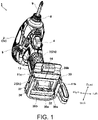
- FIG. 1 It is a perspective view of an electric tool main body 1 on which a battery pack 100 according to an example of the present invention is mounted.
- electric tools which is a form of an electrical apparatus.
- an electric tool using the battery pack 100 having a rated voltage 36 V that provides higher output is commercially available.
- a battery pack compatible with a plurality of voltages that can be mounted on both an electric tool main body having a rated voltage of 18 V and the electric tool main body 1 having a rated voltage of 36 V has been made commercially available by the applicant.
- the electric tool main body 1 shown in Fig. 1 is called an impact tool, and a tip tool 9 such as a bit is mounted on an output shaft, and fastening work is performed by applying a rotational force or a striking force in the shaft direction to the tip tool.
- the electric tool main body 1 includes a housing 2 which is an outer frame that forms an outer shape.
- the housing 2 is formed to have a substantially tubular body part 2a and a handle part 2b extending in an orthogonal direction (downward) from the vicinity of the center of the body part 2a in the shaft direction.
- An anvil (not shown in the drawing), which is an output shaft, is provided on the front side of the housing 2, a hexagonal hole (not shown) having a hexagonal cross section is formed on the output shaft, and a one-touch type tip tool holding part 8 for mounting the tip tool 9 is provided at the tip of the output shaft.
- a cross-recessed screwdriver bit is mounted as the tip tool 9.
- a trigger-shaped trigger switch 4 is provided on a part of the handle part 2b that is, in the vicinity of where the index finger comes into contact when the operator grips the handle part 2b.
- a forward/reverse switching lever 5 for switching the rotation direction of the output shaft is provided in the vicinity of the trigger switch 4.
- a battery pack mounting part 2c for mounting the battery pack 100 is formed below the handle part 2b.
- the battery pack mounting part 2c is formed to have rail parts 11a and 11b including groove parts extending parallel to each other in the front-rear direction at the inner wall parts on both the left and right sides, and a terminal part 30 is provided therebetween.
- the terminal part 30 is manufactured by integrally molding a non-conductor material such as a synthetic resin, and a plurality of metal terminals, such as a positive electrode input terminal 32, a negative electrode input terminal 37, and an LD terminal (abnormal signal terminal) 38, is cast therein.
- the short circuit terminal 39a is disposed to be separated from the lower side of the positive electrode input terminal 32, and the short circuit terminal 39a is disposed to be separated from the lower side of the negative electrode input terminal 37.
- the connection terminals for other signals, which will be described later, are not shown here.
- the terminal part 30 is formed to have a vertical surface 30a and a horizontal surface 30b which are abutting surfaces in the mounting direction (front-back direction), and the horizontal surface 30b is a surface which is adjacent to and faces an upper step surface 113 (will be described later in Fig. 2 ) when the battery pack 100 is mounted.
- a curved part 12 that abuts on a raised part 115 of the battery pack 100 is formed on the front side of the horizontal surface 30b, and a projection part 14 is formed in the vicinity of the center of the curved part 12 in the left-right direction.
- the projection part 14 also serves as a boss for screwing the housing of the electric tool main body 1 formed being divided into two in the left-right direction, and also serves as a stopper that limits the relative movement of the battery pack 100 in the mounting direction.
- Fig. 2 is a perspective view of the battery pack 100 according to the example of the present invention.
- the battery pack 100 accommodates ten lithium ion battery cells having a rated voltage of 3.6 V in a case configured with an upper case 110 and a lower case 101.
- the part extending to the rear side from the step part 112 in front of the battery pack 100 on the upper step surface 113 becomes a slot group arrangement area 120.
- a lower step surface 111 and the upper step surface 113 of the upper case 110 are formed in a stepped shape, and a plurality of slots 121 to 128 extending to the rear side from the connecting part thereof is formed.
- the slots 121 to 128 are parts which are notched to have a predetermined length in the battery pack mounting direction, and inside the notched parts, a plurality of connection terminals that can be fitted to the electric tool main body 1 or an apparatus-side terminal of an external charging device (not shown) is arranged.
- the slot 121 on the side closer to the right side surface of the battery pack 100 serves as an insertion port of the positive electrode terminal (C+ terminal) for charging
- the slot 122 serves as an insertion port of the positive electrode terminal (+ terminal) for discharging.
- the slot 127 on the side closer to the left side surface serves as an insertion port for the negative electrode terminal (- terminal).
- a plurality of signal terminals for transmitting signals to the battery pack 100, the electric tool main body 1, and the external charging device (not shown) is arranged, and here, four slots 123 to 126 for signal terminals are provided between the power terminal groups. Furthermore, the slot 123 is a spare terminal insertion port, and no terminal is provided in the present example.
- the slot 124 is an insertion port for a T terminal for outputting a signal that is identification information of the battery pack 100 to the electric tool main body or the charging device.
- the slot 125 is an insertion port for a V terminal for inputting a control signal from an external charging device (not shown).
- the slot 126 is an insertion port for an LS terminal for outputting battery temperature information by a thermistor (temperature sensitive element) (not shown) provided in contact with the cell.
- a slot 128 for the LD terminal which outputs an abnormal stop signal by the battery protection circuit (not shown) included in the battery pack 100 is further provided.
- Two rail parts (rail grooves) 118a and 118b are formed on the side surface of the upper step surface 113 of the battery pack 100.
- the rail parts 118a and 118b are formed such that the longitudinal direction is parallel to the mounting direction of the battery pack 100.
- the front end part is an open end
- the rear end part is a closed end connected to the front wall surface of the raised part 115.
- a raised part 115 formed so as to be raised is formed on the rear side of the upper step surface 113.
- a recessed stopper part 119 is formed in the vicinity of the center of the raised part 115.
- the stopper part 119 becomes a contact surface of the projection part 14 (refer to Fig.
- the battery pack 100 of the present example can be mounted on the electric tool main body for 18 V and the electric tool main body 1 for 36 V.
- the output of the battery pack 100 is automatically set for 18 V
- the output of the battery pack 100 is automatically set for 36 V.
- the output voltage of the battery pack is fixed, but in the battery pack 100, a plurality of cell units is provided in a case accommodating the battery cells, and it is possible to select whether to output the voltage while the cell units are connected to each other in series or to output the voltage while the cell units are connected to each other in parallel depending on the connection means, and thus it is possible to support apparatuses having different voltages.
- This battery pack eliminates the need to prepare different types of battery packs when using a plurality of electrical apparatuses. Further, no special operation is required when switching the voltage, and there is no risk of an operation error.
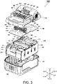
- Fig. 3 is a developed perspective view of the battery pack 100 of Fig. 2 .
- the housing of the battery pack 100 is formed by the upper case 110 and the lower case 101 that can be separated in the up-down direction, and ten battery cells are accommodated in the internal space of the lower case 101.
- the ten battery cells are provided in two sets of five cell units, in which the cell units are connected to each other in series. A rated output of 36 V (high voltage output) can be obtained by connecting these two cell units in series, and a rated output of 18 V (low voltage output) can be obtained by connecting these cell units in parallel.
- high voltage for example, electric tool main body 1
- the upper case 110 and the lower case 101 are fixed by four screws (not shown).
- a plurality of battery cells (not shown) is fixed by a separator 145 made of a non-conductor such as synthetic resin in a state where batteries are stacked five each in two stages.
- the separator 145 holds a plurality of battery cells such that only both the left and right sides, which are both ends of the battery cell, are open.
- a circuit board 150 is fixed on the upper side of the separator 145.
- a slot group arrangement area 160 is provided slightly in front of the center of the circuit board 150 in the front-rear direction, and here, a plurality of connection terminals (161, 162, 164 to 168, 171, 172, 177) is arranged in the horizontal direction and fixed by soldering, and electrical connection is made between these connection terminals and a circuit pattern (not shown).
- various electronic elements such as a battery protection IC, a microcomputer, a PTC thermistor, a resistor, a capacitor, a fuse, and a light emitting diode are mounted.
- the material of the circuit board 150 is a printed board on which pattern wiring is printed by a conductor such as a copper foil on a board impregnated with a resin having insulating properties for the material, and a single-layer board, a double-sided board, or a multilayer board can be used.
- the wiring pattern is formed on the upper surface (a surface on the upper side which is a front surface and can be seen from Fig. 3 ) and the lower surface (back surface) of the circuit board 150 by using the double-sided substrate.
- connection terminal group of the battery pack 100 of the present example only two positive electrode terminals and two negative electrode terminals are provided.
- the number of other connection terminals, that is, the T terminal, the V terminal, the LS terminal, and the LD terminal (none of which are shown) of the slots 124 to 126 and 128 is one, and has the same terminal shape as that of the voltage-fixed battery pack, which has been conventionally used.
- the positive electrode terminals (161, 162, 171, 172) and the negative electrode terminals (167, 177) are arranged at places significantly separated in the left-right direction, and three signal terminals (the T terminal 164, the V terminal 165, the LS terminal 166) are provided therebetween.
- the power terminals as components for the power terminals, a total of two sets of arm parts including one set of arm parts extending in the horizontal direction provided on the upper left and right sides, and one set provided on the lower left and right sides, are used. Furthermore, the signal terminals (164 to 166, 168) also have two upper and lower arm parts, which are formed of the same member and have the same electrical potential.
- the LD terminal 168 is provided on the left side of the negative electrode terminal pair (167, 177).
- the LD terminal 168 is also formed so as to have two sets of arm parts, one on the upper side and the other on the lower side. All signal terminals (164 to 166, 168) are fixed by soldering on the back surface side, with each leg part penetrating from the front surface to the back surface through a plurality of attaching holes formed on the circuit board 150.
- an electronic element (not shown) is mounted on the circuit board 150, and a plurality of connection terminals is fixed by soldering, and then is fixed to the separator 145 by screws (not shown).
- the lower case 101 has a substantially rectangular parallelepiped shape with an open upper surface, and is configured with a bottom surface, and a front surface wall, a rear surface wall, a right side wall, and a left side wall extending in a vertical direction with respect to the bottom surface.
- the internal space of the lower case 101 has a shape suitable for accommodating the separator 145.
- a slit 104 is provided substantially at the center of the front surface wall of the lower case.
- a slit 134 of the upper case 110 is used as an inflow port for taking in outside air from the slit 104 of the lower case 101 into the internal space of the battery pack 100 when charging with the charging device, and cooling the inside of the battery pack 100, and then allowing the cooling air to flow into the charging device through the slit 134 of the upper case 110, and the slit 104 of the lower case 101 is used as an intake port of the cooling air.
- the flow of the cooling air may be reversed.
- connection connection between the battery cell and the circuit board 150 from the battery cell side to the output circuit board 150 is performed through lead-out tabs 261, 266, 271, and 276 for connection extending in the upward direction in a plate shape.
- the end parts 294 and 296 to 299 of the lead wire from the intermediate connection point of the battery cells connected in series are arranged to extend in the upward direction and are soldered onto the circuit board 150.
- the intermediate lead-out tabs 262 and 263 from the intermediate connection points of the battery cells connected to each other in series are connected to the circuit board 150, and arranged to extend in the upward direction. Screw bosses 146 and 147 for fixing the circuit board 150 are formed on the upper side of the separator 145.
- the separator 145 is a stack of ten battery cells, five each, in two upper and lower stages.
- the battery cell is inserted into the cylindrical space of the separator 145.
- As the ten battery cells a lithium ion battery cell having a diameter of 18 mm and a length of 65 mm that can be charged and discharged plural times, that is a so-called 18650 size, is used.
- the axes of each battery cell are stacked such that the battery cells are parallel to each other, the adjacent cells are arranged such that the directions thereof are alternately opposite to each other, and the positive electrode terminal and the negative electrode terminal of the adjacent battery cells are connected to each other by using a metal connection plate (not shown in the drawing). In this manner, the five battery cells are connected to each other to form a cell unit.
- two sets of cell units are accommodated.
- the positive electrode of an upper cell unit 130 is connected to the circuit board 150 by using the lead-out plate on which the lead-out tab 261 is formed, and the negative electrode of the upper cell unit 130 is connected to the circuit board 150 by using the lead-out plate on which the lead-out tab 266 is formed.
- the positive electrode of a lower cell unit 140 is connected to the circuit board 150 by using a lead-out plate 270 on which the lead-out tab 271 is formed, and the negative electrode of the lower cell unit 140 is connected to the circuit board 150 by using the lead-out plate on which the lead-out tab 276 is formed.
- a narrow part 272 that plays the role of a fuse 182 (refer to Fig.
- the lead-out plate 270 is formed between the lead-out plate 270 and the lead-out tab 271.
- the narrow part 272 is in a disconnected state by melting when a large current having a threshold I 1 or more continues for a predetermined period of time or longer, and accordingly, the electrical connected state between the lead-out plate 270 and the lead-out tab 271 is negated.
- the lead-out tab 261 for the upper cell unit 130 also performs the function of a fuse 152 (refer to Fig. 6 which will be described later) by forming a narrow part.
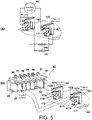
- FIG. 4 is a partial perspective view showing shapes of the positive electrode terminals (162 and 172) and the negative electrode terminals (167 and 177) in the present example, and a view showing a connection circuit at the time of high voltage output
- (B) of Fig. 4 is a partial perspective view showing a connection status between the terminal part 30 of the high-voltage electrical apparatus main body and the terminal on the battery pack 100 side.
- (A) of Fig. 4 in the connection terminal group of the battery pack 100 of the present example, only two positive electrode terminals and two negative electrode terminals are provided.
- the upper positive electrode terminal 162 and the lower positive electrode terminal 172 are arranged side by side in the slot 122 (refer to Fig. 3 ).
- the upper positive electrode terminal 162 and the lower positive electrode terminal 172 are formed by pressing a metal plate, the leg parts are penetrated through the circuit board 150, and the penetrated side is fixed by soldering or the like.
- the upper positive electrode terminal 162 and the lower positive electrode terminal 172 are arranged at a distance from each other, are in a physically non-contact state, and are electrically in a non-conducting state in the battery pack 100.
- the upper negative electrode terminal 167 and the lower negative electrode terminal 177 are arranged side by side.
- the upper negative electrode terminal 167 and the lower negative electrode terminal 177 are arranged at a distance from each other, are in a physically non-contact state, and are electrically in a non-conducting state in the battery pack 100.
- the upper positive electrode terminal 162 and the upper negative electrode terminal 167, and the lower positive electrode terminal 172 and the lower negative electrode terminal 177 are the same metal components.
- the lower cell unit 140 in which five lithium ion battery cells are connected to each other in series and the upper cell unit 130 in which the battery cells are connected to each other in series are accommodated, a positive electrode of the upper cell unit 130 is connected to the upper positive electrode terminal 162 corresponding to a first positive electrode terminal, and a negative electrode of the upper cell unit 130 is connected to the lower negative electrode terminal 177 corresponding to a first negative electrode terminal.
- the positive electrode of the lower cell unit 140 is connected to the lower positive electrode terminal 172 corresponding to a second positive electrode terminal, and a negative electrode of the lower cell unit 140 is connected to the upper negative electrode terminal 167 corresponding to a second negative electrode terminal.
- the upper and lower sides of the cell unit referred to here do not refer to the physical position of whether the battery cell is in the upper stage or the lower stage in the lower case 101, but when two cell units are connected in series, the cell unit positioned on the ground side is referred to as “lower cell unit”, the cell unit positioned on the higher voltage side when connected in series is referred to as “upper cell unit”, and the electrical potential is the reference.
- FIG. 4 is a view showing a connection relationship between the terminal part 30 of the electric tool main body 1 having a rated voltage of 36 V and the connection terminals (162, 167, 172, 177) on the battery pack 100 side.
- the terminal part 30 is provided in the battery pack mounting part 2c of the electric tool main body 1.
- the terminal part 30 is provided with apparatus-side terminals (32, 39a, 34 to 36, 37, 39b, 38) corresponding to the slots 121 to 128 (refer to Fig. 2 ) of the battery pack 100, and is fixed to be cast into a synthetic resin base 31.
- a short circuit 39 is a short bar made of a metal plate, and as shown in Fig.
- the connection terminal part on the upper side of the base 31 and a part which is the plate-shaped terminal part on the lower side and has the same reference numeral are configured with an electrically conductive metal plate.
- the apparatus-side terminal is not provided at the position corresponding to the slot 123 (refer to Fig. 3 ).
- the positive electrode input terminal 32 and the negative electrode input terminal 37 for receiving power are made in a smaller size than other terminals, and are provided on the upper sides of the short circuit terminals 39a and 39b, respectively.
- the positive electrode input terminal 32 and the short circuit terminal 39a are not conducting.
- the negative electrode input terminal 37 and the short circuit terminal 39b are not conducting.
- the positive electrode input terminal 32 is fitted only to the upper positive electrode terminal 162, and the negative electrode input terminal 37 is fitted only to the upper negative electrode terminal 167. Further, since the terminal part 30 of the electric tool main body 1 is provided with small short circuit terminals 39a and 39b for short-circuiting the lower positive electrode terminal 172 and the lower negative electrode terminal 177, the lower positive electrode terminal 172 and the lower negative electrode terminal 177 are electrically connected to each other by the short circuit 39 when the battery pack 100 is mounted.
- the positive electrode input terminal 32 is configured with a terminal part formed in a flat plate, which is a part that fits to the upper positive electrode terminal 162, and a terminal part that protrudes to the upper part of the base 31, which is a part that is connected to the circuit board side on the electric tool main body 1 side.
- the positive electrode input terminal 32 is cast into a base 31 made of synthetic resin.
- the negative electrode input terminal 37 is the same as the positive electrode input terminal 32, and the height of the terminal plate is set to be slightly smaller than half of that of the other terminals (34 to 36, 38) plates.
- the other terminals (34 to 36, 38) are terminals for signal transmission. Recesses 31a and 31b for being sandwiched by the housing are provided on the front side and the rear side of the synthetic resin base 31 of the terminal part 30.
- the negative electrode input terminal 37 and the short circuit terminal 39b are inserted into the inside through the same slot 127 (refer to Fig. 2 ), and are fitted into the upper negative electrode terminal 167 and the lower negative electrode terminal 177, respectively.
- the negative electrode input terminal 37 is press-fitted between arm parts 167a and 167b of the upper negative electrode terminal 167 so as to expand between the fitting parts.
- the short circuit terminal 39b is press-fitted so as to expand between arm parts 177a and 177b of the lower negative electrode terminal 177.
- the output of the series connection of the lower cell unit 140 and the upper cell unit 130 that is, the rated voltage of 36 V is output from the battery pack 100.
- FIG. 5 are views showing a connected state when the battery pack 100 of the present example is mounted on a conventional electric tool main body (not shown) having a rated voltage of 18 V.
- the terminal part 80 is provided in the battery pack mounting part of the electric tool main body. Connection terminals such as a positive electrode input terminal 82 and a negative electrode input terminal 87 are fixed to the terminal part 80 so as to be cast into a synthetic resin base 81.
- the other apparatus-side terminals (84 to 86, 88) are the same as the apparatus-side terminals (34 to 36, 38) fixed to the terminal part 30 of Fig. 4 .
- the terminal part of the positive electrode input terminal 82 is fitted and press-fitted so as to expand the open end parts of both the upper positive electrode terminal 162 and the lower positive electrode terminal 172, an area at a part on the upper side of the terminal part of the positive electrode input terminal 82 comes into contact with the upper positive electrode terminal 162, and an area at a part on the lower side comes into contact with the lower positive electrode terminal 172.
- the terminal part of the positive electrode input terminal 82 By simultaneously fitting the terminal part of the positive electrode input terminal 82 to the arm parts 162a and 162b of the upper positive electrode terminal 162 and the arm parts 172a and 172b of the lower positive electrode terminal 172, the two positive electrode terminals (162 and 172) are in a short circuit state.
- the terminal part of the negative electrode input terminal 87 is fitted and press-fitted so as to expand the open end parts of both the upper negative electrode terminal 167 and the lower negative electrode terminal 177, an area at a part on the upper side of the terminal part of the negative electrode input terminal 87 comes into contact with the upper negative electrode terminal 167, and an area at a part on the lower side comes into contact with the lower negative electrode terminal 177.
- the two negative electrode terminals (167 and 177) are in a short circuit state, and the output of the parallel connection of the lower cell unit 140 and the upper cell unit 130, that is, the rated voltage of 18 V is output to the electric tool main body.
- the terminal part described above corresponds to a connection unit.
- the output of the battery pack 100 is automatically switched by mounting the battery pack 100 of the present example to either the electric tool main body for 18 V or the electric tool main body 1 for 36 V. Since this voltage switching is automatically performed according to the shape of the terminal part on the electric tool main body side, there is no concern about occurrence of voltage setting error.
- the battery pack 100 When the battery pack 100 is charged using an external charging device (not shown), it is possible to perform charging with the same charging device as that of the conventional 18 V battery pack.
- the positive electrode terminals 161 and 171 for charging (refer to Fig. 3 ) having the same shape as that of the upper positive electrode terminal 162 and the lower positive electrode terminal 172 are provided, and thus, instead of the positive electrode terminals (162, 172) for discharging, the positive electrode terminals 161 and 171 for charging may be connected to the positive electrode terminals of the external charging device (not shown).
- the battery pack 100 can be charged by using the charging device for 18 V with the lower cell unit 140 and the upper cell unit 130 connected in parallel.
- Fig. 6 is a block diagram showing an internal circuit of the battery pack 100 of the present example.
- the battery pack 100 includes the upper positive electrode terminal (upper +) 162, the lower positive electrode terminal (lower +) 172, the upper negative electrode terminal (upper -) 167, the lower negative electrode terminal (lower -) 177, the LS terminal 166, and the LD terminal 168.
- the battery pack 100 is provided with the upper positive electrode terminal (upper C +) 161 and the lower positive electrode terminal (lower C +) 171 for charging, and other signal terminal groups (T terminal, V terminal), but here, these are omitted in the drawings.
- the output of the upper cell unit 130 is connected to the upper positive electrode terminal 162 and the lower negative electrode terminal 177.
- the positive electrode (+ output) of the upper cell unit 130 is connected to the upper positive electrode terminal 162
- the negative electrode (- output) of the upper cell unit 130 is connected to the lower negative electrode terminal 177.
- the positive electrode (+ output) of the lower cell unit 140 is connected to the lower positive electrode terminal 172
- the negative electrode (- output) of the lower cell unit 140 is connected to the upper negative electrode terminal 167.
- the LS terminal 166 corresponds to a charge prevention signal output terminal
- the LD terminal 168 corresponds to a discharge prevention signal output terminal.
- a discharge prevention signal output circuit that electrically connects the control unit 190 and the LD terminal 168 is provided.
- the discharge prevention signal output circuit includes the control unit 190, a line (second circuit part) connecting the control unit 190 and the switching element 191 to each other, a line (third circuit part) connecting the switching element 191 and the LS terminal 166 to each other, the switching element 191, and the LD terminal 168.
- the discharge prevention signal output circuit outputs a discharge prevention signal 187 (LD signal 250) so as to stop (prevent) the discharge of the battery pack 100 when a chattering phenomenon occurs, and then maintains a discharging prevented state such that the battery pack 100 cannot be discharged even when the battery pack 100 is connected to another electrical apparatus main body.
- a charge prevention signal output circuit that electrically connects the control unit 190 and the LS terminal 166 is provided.
- the charge prevention signal output circuit includes the control unit 190, a line (first circuit part) connecting the control unit 190 and the LS terminal 166 to each other, and the LS terminal.
- the charge prevention signal output circuit outputs a charge prevention signal 188 when the chattering phenomenon occurs during discharging in a state where the battery pack 100 is connected to the electrical apparatus main body, and the battery pack 100 cannot be charged even when the battery pack 100 is connected to the charging device 300.
- the control unit 190 is configured to output the discharge prevention signal 187 (LD signal 250) and also output the charge prevention signal 188 (LS signal 255) when the chattering phenomenon is detected.
- the upper cell unit 130 and the lower cell unit 140 are provided with the protection ICs 151 and 181 for monitoring the voltage of the battery cell, respectively, and the control unit 190 having a microcomputer is connected to these protection ICs 151 and 181.
- the protection IC 151 is an integrated circuit which is commercially available as a "protection IC for a lithium ion battery" and executes a cell balance function, a cascade connection function, and a disconnection detection function in addition to an overcharge protection function and an overdischarge protection function, by inputting the end-to-end voltage of each battery cell of the upper cell unit 130.
- the protection IC 151 when the voltage of any battery cell of the upper cell unit 130 decreases to a predetermined lower limit value and becomes an overdischarged state, the protection IC 151 outputs a signal (high signal) 156 indicating overdischarge to the control unit 190. Further, when the battery pack 100 is mounted on an external charging device (not shown) and charging is performed, in a case where it is detected that the voltage of one of the battery cells of the upper cell unit 130 exceeds a predetermined upper limit value to be in an overcharged state, the protection IC 151 outputs an overcharge signal (high signal) 155 indicating the overcharged state to the control unit 190.
- the protection IC 181 is connected to the lower cell unit 140.
- the protection IC 181 monitors the voltage of each battery cell in the lower cell unit 140, and in a case where a state (overdischarged state) where the voltage of one of the battery cells decreases to a predetermined lower limit value is detected, the protection IC 181 outputs an overdischarge signal (high signal) 186 to the control unit 190. Further, when the battery pack 100 is mounted on an external charging device (not shown) and charging is performed, in a case where it is detected that the voltage of one of the battery cells of the lower cell unit 140 exceeds a predetermined upper limit value, the protection IC 181 outputs an overcharge signal (high signal) 185 indicating the overcharged state to the control unit 190.
- the control unit 190 is further provided in the circuit of the lower cell unit 140, that is, in the circuit between the lower positive electrode terminal 172 and the upper negative electrode terminal 167.
- the control unit 190 including the protection IC 181 and the microcomputer (micro controller unit) is disposed in the circuit provided in parallel with the lower cell unit 140.
- the output (overdischarge signal 156, overcharge signal 155) from the protection IC 151 and the output (overdischarge signal 186, overcharge signal 185) from the protection IC 181 are input to the control unit 190.
- the control unit 190 monitors the voltages of the upper cell unit 130 and the lower cell unit 140.
- the voltage adjustment of each battery cell included in the upper cell unit 130 and the lower cell unit 140 is performed by the respective protection ICs 151 and 181.
- the control unit 190 monitors the current value and the cell temperature, and also monitors the state of the upper cell unit 130 and the lower cell unit 140 to integrate and control the operating conditions of both, for example, the voltage balance between the cell units is adjusted.
- a shunt resistor 189 for measuring the current value is provided on the ground side of the lower cell unit 140, and the current detection circuit 184 detects the current value by measuring the end-to-end voltage of the shunt resistor 189.
- the output of the current detection circuit 184 is input to the control unit 190.
- the control unit 190 transmits the discharge prevention signal 187 to the electrical apparatus main body side through the LD terminal 168. Further, the control unit 190 outputs the charge prevention signal 188 to a charging device (not shown) through the LS terminal 166.
- the control unit 190 is provided with a storage device (not shown), and appropriately stores software, parameters, and the like operated by a microcomputer (not shown). Further, cell temperature detecting means 193 is connected to the control unit 190. Outputs of a plurality of temperature sensors (not shown) is connected to the cell temperature detecting means 193. As the temperature sensor, a thermistor can be used, and one or more thermistors are provided at a location in contact with or close to the upper cell unit 130, and another thermistor is provided at a location in contact with or close to the lower cell unit 140.
- the cell temperature detecting means 193 measures the temperatures of each of the upper cell unit 130 and the lower cell unit 140 by utilizing the change in the electric resistance of the thermistor with respect to the temperature change, and outputs the temperature to the control unit 190.
- the power source for driving the control unit 190 is generated by the power supply circuit (power supply part) 180 connected to the lower cell unit 140, and a reference voltage VDD is supplied to the control unit 190.
- the battery pack 100 of the present example is a voltage switching type for 18 V and 36 V
- the control unit 190 microcomputer
- the control unit 190 microcomputer
- the protection circuit on the upper cell unit 130 side the ground potential of the control unit 190 changes when the two cell units are connected to each other in series and in parallel. Therefore, the power supply circuit 180 is provided on the lower side (ground side) such that the ground potential of the power supply circuit 180 does not change.
- the control unit 190 can switch between holding and negating the power supply voltage (VDD) applied to itself, and can switch between a normal operation state (normal mode), an operation function limited state (so-called sleep mode), and an operation stop state (so-called shutdown).
- the output of an upper voltage detection circuit 157 connected to the upper positive electrode terminal 162 is input to the control unit 190.
- This output indicates the potential of the upper cell unit 130 when the battery pack 100 is not mounted on the electric tool main body 1 or an external charging device (not shown).
- the upper positive electrode terminal 162 and the lower positive electrode terminal 172 are connected to each other, and thus each positive electrode of the upper cell unit 130 and the lower cell unit 140 have the same potential, and each negative electrode has the same potential.
- the control unit 190 can determine whether the battery pack 100 is not mounted, is mounted on the apparatus main body for low voltage, or is mounted on the apparatus main body for high voltage. Furthermore, in order to detect the potential of the lower positive electrode terminal 172, the control unit 190 may be configured to be capable of acquiring the positive electrode potential of the highest-order battery cell among the battery cells in the lower cell unit 140.
- the discharge prevention signal 187 When the power supply from the battery pack 100 must be stopped, for example, when an excessive current during discharge, a decrease (overdischarge) in cell voltage during discharge, an abnormal rise (overtemperature) in cell temperature, and the like occur, by transmitting the discharge prevention signal 187 to the electric tool main body side through the control unit 190, the operation of the electric tool main body can be stopped quickly.
- the transmission of the discharge prevention signal 187 is performed by dropping the LD terminal 168 to the ground potential by conducting the switching element 191 by outputting a high signal from the I/O port of the control unit 190.
- the state of the control unit 190 has three stages of normal, sleep, and shutdown. Normal is a state where the control unit 190 is always activated. Sleep is a mode in which the operation of the functions of the external circuit or the control unit 190 itself is limited to the minimum, and the control unit 190 is activated intermittently by itself, for example, an operation such as stopping for 240 milliseconds after 10 milliseconds of activation is repeated. Shutdown is a state where the reference voltage VDD is not supplied at all, and the control unit 190 is completely stopped.
- the control unit 190 can operate not only when the battery pack 100 is mounted on the electric tool main body but also when the battery pack 100 is not mounted.
- the control unit 190 shifts to the sleep state.
- the control unit 190 detects an increase in the current value detected by the current detection circuit 184 and is restored to the normal state.
- Fig. 7 is a circuit diagram of the electric tool main body 1 (electrical apparatus for high voltage) on which the battery pack 100 is mounted. The right side is the battery pack 100, and the specific circuit configuration is the same as that shown in Fig. 6 , and thus the repeated description will be omitted.
- the terminal part 30 (refer to Fig. 4 ) of the electric tool main body 1 having a rated voltage of 36 V includes the short circuit 39 for short-circuiting the lower positive electrode terminal 172 and the lower negative electrode terminal 177. In this manner, by providing the terminal part 30 (refer to Fig.
- a series connection circuit of the upper cell unit 130 and the lower cell unit 140 can be established only by mounting the battery pack 100 of the present example having two positive electrode terminals (162, 172) and two negative electrode terminals (167, 177).
- the battery pack 100 of the present example having two positive electrode terminals (162, 172) and two negative electrode terminals (167, 177).
- the upper positive electrode terminal 162 positioned on the upper side is connected to the positive electrode input terminal 32 of the electric tool main body 1
- only the negative electrode terminal 167 positioned on the upper side is connected to the negative electrode input terminal 37.
- the lower positive electrode terminal 172 positioned on the lower side and the lower negative electrode terminal 177 positioned on the lower side are connected to each other by the short circuit 39.
- the electric tool main body 1 includes a control unit 20 for controlling the rotation of the motor 3.
- a microcomputer is included in the control unit 20, and a reference voltage VDD1 (5 V or 3.3 V) for driving is supplied to the control unit 20.
- the reference voltage VDD1 is supplied by the power supply circuit 21 that inputs the end-to-end voltage of the positive electrode input terminal 32 and the negative electrode input terminal 37.
- the voltage detection circuit 22 measures the voltage (voltage of the battery pack 100) between the positive electrode input terminal 32 and the negative electrode input terminal 37, and the output thereof is output to the control unit 20.
- the voltage (V +) of the positive electrode input terminal 32 is input from the voltage detection circuit 22 to the input port of the control unit 20.
- the control unit 20 outputs a signal for turning on the switching element 25 through the output port (A/D output terminal).
- the switching element 25 is a switch for stopping the motor 3 under the control of the microcomputer of the control unit 20 when the discharge prevention signal 187 (LD signal) is received.
- a switch (SW) state detection circuit 23 is a circuit that detects whether the state of the trigger switch 4 is on or off, and outputs an on signal to the control unit 20 when the lever of the trigger switch 4 is pulled even a little.
- the control unit 20 inputs or outputs various signals such as various control signals, input signals from sensors, and control signals to the battery pack 100.
- the current detection circuit 24 outputs the magnitude of the current value flowing through the motor 3 to the control unit 20 by measuring the end-to-end voltage of the shunt resistor 26.
- the LD terminal 38 is connected to the input/output port of the control unit 20 through the resistor 28.
- the resistor 28 and the control unit 20 are connected to the reference voltage VDD1 through a resistor 27.
- the control unit 190 on the battery pack 100 side outputs (sets high) the discharge prevention signal 187
- the switching element 191 conducts, and accordingly the LD terminals 168 and 38 (LD signal which will be described later) are dropped to the ground potential.
- the input potential of the control unit 20 connected to the resistor 28 changes to the voltage dividing potential of the reference voltage VDD1 by the resistors 27 and 28, and thus the control unit 20 can detect that the battery pack 100 has instructed to prevent discharge.
- the LD terminal 38 corresponds to a discharge prevention signal input terminal.
- Fig. 8 is an input/output circuit diagram when the battery pack 100 of the present example is connected to the external charging device 300.
- the configuration on the battery pack 100 side is the same as the circuit shown in Fig. 6 , but the opposite-side apparatus (electrical apparatus main body) to be mounted is the charging device 300.
- the charging device 300 includes a control unit 320 having a microcomputer or the like, and charges the battery pack 100 with the output of the power supply circuit 310 in the same manner as the battery pack having a rated voltage of 18 V. Since a positive electrode terminal 332 and a negative electrode terminal 337 of the charging device 300 have the same shape as the positive electrode input terminal 82 and the negative electrode input terminal 87 shown in Fig.
- the power supply circuit 310 rectifies a commercial AC power source 301 to obtain a predetermined direct current and voltage.
- a constant voltage power supply circuit that generates a reference voltage VDD2 for operation of the control unit 320 from the output of the power supply circuit 310 is also included.
- the magnitude of the current output from the power supply circuit 310 to the battery pack 100 is detected by a current detection circuit 315 using a shunt resistor 311 and output to the microcomputer of the control unit 320.
- a battery voltage detection circuit 317 is provided, and the voltage between the positive electrode terminal 332 and the negative electrode terminal 337 is measured and output to the microcomputer of the control unit 320.
- the charging device 300 is provided with an LS terminal 336 and is connected to the LS terminal 166 on the battery pack 100 side.
- the LS terminal 336 corresponds to a charge prevention signal input terminal.
- the charge prevention signal 188 is output from the microcomputer of the control unit 190 of the battery pack 100, and during normal charging, the charge prevention signal 188 is not output until the battery voltage reaches full charge (low signal state), but the charge prevention signal 188 is output when the battery voltage reaches full charge (high signal state).
- the microcomputer of the control unit 320 stops charging the battery pack 100 by stopping the output of the power supply circuit 310. In the present example, even when the microcomputer of the control unit 190 determines that the battery pack 100 is in an abnormal state before reaching a melted and cut state by the fuses 152 and 182, the charge prevention signal 188 is continuously output.
- the charge prevention signal 188 By keeping the charge prevention signal 188 at the high level in this manner, it is possible to prevent the battery pack 100 from being charged. This operation that does not cause charging is the same as the melted and cut state by the fuses 152 and 182 when viewed from the battery cell side. Furthermore, since the charging device 300 does not use the output signal of the LD terminal 168, the LD terminal for receiving the discharge prevention signal output from the charging device 300 side is not provided.
- the microcomputer of the control unit 320 may be configured to be capable of receiving the output signal of the LD terminal 168. Furthermore, the control unit 320 may monitor the voltage of the battery pack 100 through the battery voltage detection circuit 317, and the control unit 320 may perform control to stop charging when the voltage of the battery pack 100 reaches full charge.
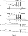
- Fig. 9 is a view showing each signal waveform when the chattering phenomenon occurs in the battery pack 100 of the present example.
- the horizontal axis of (A) to (D) of Fig. 9 is time (unit: millisecond), and the time on each horizontal axis is shown together.
- (A) of Fig. 9 is a waveform diagram of a current value 230, and the vertical axis is a current (unit: A).
- the current value 230 is detected by the microcomputer of the control unit 190 using the current detection circuit 184.
- the first threshold current I 1 is a current threshold (for example, 200A) for detecting the generation of a pulsed abnormal current in the present example
- the second threshold current I 2 is a rated shutdown current (for example, 250A) that affects the melting and cutting of the fuses 152 and 182 in the circuit illustrated in Fig. 6 .
- the pulsed current 231 flows from time t 2 , and the current in a state where the first threshold current I 1 is exceeded continues for a duration DT1.
- pulsed currents 232 and 233 due to a short circuit or the like for a short period of time flow from time t 3 and t 4 for the durations DT2 and DT3.
- the control unit 20 of the electrical apparatus main body stops (shuts off) the discharge of the battery pack 100, and accordingly, the current value 230 becomes zero. Furthermore, even when the operator turns off the trigger switch 4 at time t 6 or between times t 5 and t 6 , the current value 230 becomes zero.
- FIG. 9 shows a case of a voltage value 240 (unit: volt) between both terminals of the cell unit.
- the terminal voltage measured by the upper voltage detection circuit 157 is shown.
- the battery pack 100 is connected to the 36 V electrical apparatus main body, the total voltage of the upper cell unit 130 and the lower cell unit 140 is shown, and when the battery pack 100 is connected to the 18V electrical apparatus main body, the voltage of the upper cell unit 130 and the lower cell unit 140 in a parallel connection state is shown.
- the voltage value 240 decreases due to a voltage drop according to the magnitude of the current value 230.
- the voltage decreases significantly at first as shown by the arrow 240a, and then the voltage decreases according to the current value 230 shown by the arrow 230b, and is settled to the voltage value 240 as shown by the arrow 240b. Furthermore, since the voltage value 240 in the state of the arrow 240b is not in a fully charged state where the battery pack 100 cannot be charged any more (because the voltage or capacity is smaller than that in the fully charged state), charging starts when the battery pack 100 is connected to the charging device 300 in a normal state (for example, the temperature of the battery cell is in a normal range (chargeable temperature range)).
- the voltage value 240 when a short circuit state corresponding to the arrows 231 to 233 occurs at short time intervals, the voltage value 240 also causes a sudden drop state for a short time as shown by the arrows 241 to 243.
- the voltage value 240 continues to be lower than a voltage threshold Vi (first threshold voltage) for a predetermined time DT 1 from time t 2 , and then the voltage value 240 is lowered again to be lower than the voltage threshold V 1 at time t 3 when the time period IT 1 has elapsed.
- the voltage value 240 continues to be lower than the voltage threshold Vi for a predetermined time DT 2 from time t 3 , the voltage value 240 is restored to the state higher than the voltage threshold Vi.
- the voltage value 240 decreases again to be lower than the voltage threshold Vi at the time t 4 when the time period IT 2 has elapsed.
- the voltage value 240 continues to be lower than the voltage threshold V 1 for a predetermined time DT 3 from time t 4 , at time t 5 , the voltage value 240 is restored to the state higher than the voltage threshold Vi.
- the LD signal 250 is output from the battery pack 100, the control unit 20 of the electrical apparatus main body (electric tool main body 1) stops (shuts off) the discharge of the battery pack 100, and accordingly, the current value 230 becomes zero, and the voltage returns to the battery voltage when there is no load.
- the voltage threshold Vi may be a voltage lower than the operating voltage (VDD) of the control unit 190. Otherwise, a value (for example, 1.5 V) smaller than the overdischarge threshold (2.5 V per one battery cell) may be set as the voltage threshold Vi.
- the LD signal is a signal for the microcomputer of the control unit 190 to transmit the discharge prevention signal 187 to the electrical apparatus main body side, and is connected to the LD terminal 38 or 88 on the electrical apparatus main body side and the LD terminal 168 on the battery pack 100 side.
- the potential (LD signal 250) of the LD terminal is high, the discharge from the battery pack 100 is allowed.
- the LD signal 250 is transmitted to the microcomputer of the control unit 20 on the connected electrical apparatus main body (electric tool main body 1) side, or is connected to the gate signal of the switching element connected in the power path on the electrical apparatus main body side.
- the microcomputer of the control unit 190 switches the LD signal 250 from high to low (switches the discharge prevention signal 187 from low to high), and accordingly, the subsequent use of the battery pack 100 is prevented. Furthermore, when the use of the battery pack 100 is prevented, the battery pack 100 cannot be used even when the temperature of the battery pack 100 is within the normal range, for example.
- the LD signal 250 is switched from high to low at time t 5 , and discharge is stopped (the use of the battery pack 100 is prevented) at time t 6 thereafter.
- the time period between the time t 5 and the time t 6 is a time period (delay time) from the time when the LD signal 250 is output until the control unit 20 of the electrical apparatus main body receives (recognizes) the LD signal 250 and shuts off (stops) the discharge (current).
- the discharge (current) may be immediately shut off at time t 5 .
- the LS signal 255 is changed from low to high at time t 5 as shown in (D) of Fig. 9 .
- the LS signal 255 is a signal for allowing the charging operation of the charging device 300. When the LS signal 255 is in a low state, the charging is possible, but when the LS signal 255 is in a high state, the charging operation of the charging device 300 is prevented.
- the LS signal 255 is the same signal as the charge prevention signal 188.
- any method may be adopted as the method of outputting the discharge prevention signal and the charge prevention signal and the assignment of the high and low states, and what kind of signal prevents the supply of power to the electrical apparatus main body having a power load, and what kind of signal prevents the supply of power from the charging device is optional.
- the signal indicating the prevented state may be continuously output (maintained) thereafter (the state of Fig. 9 )
- the output may be stopped after a predetermined period of time after the prevention signal is output, and the prevention signal may be output again when connected to another electrical apparatus main body (electric tool main body or charging device). Otherwise, the control unit 190 may be shut down such that the user cannot negate the shutdown.
- Fig. 13 is a waveform diagram for describing a power shutoff state by the fuses 152 and 182 of the related art.
- the fuses 152 and 182 are electric components provided to prevent heating, damage, or ignition of the power path and the battery cell due to a large current exceeding the rating flowing to the battery pack 100 and the external electrical apparatus main body side, and usually operate as conductors with almost no resistance.
- the built-in alloy components are melted and cut by Joule heating. Accordingly, the power path is cut off and made in a non-conducting state to protect the battery pack 100 and the external electrical apparatus main body.
- the fuse has a rating, the shutoff characteristics change depending on the magnitude exceeding the second threshold current I 2 and the duration thereof, and the time interval from time t 10 to time t 11 is not constant to some extent.
- the characteristics of the fuses 152 and 182 are not essential parts of the present invention, further description thereof will be omitted.
- Fig. 10 is a flowchart showing a detection procedure of the chattering phenomenon in the battery pack 100 of the present example.
- the series of procedure shown in Fig. 10 can be executed by software by a program in which the microcomputer included in the control unit 190 is stored in advance.
- the variables used here are as follows. DT: Duration of the state where the battery voltage is less than the first threshold voltage (predetermined value VI), IT: Time period from the time when the voltage drop when the voltage finally becomes less than the first threshold voltage disappears, n: The number of times of voltage drop when the battery voltage is less than the first voltage threshold Vi
- the microcomputer determines whether or not the unit voltage of the upper cell unit 130 is lower than the first threshold voltage Vi by using the output of the upper voltage circuit 157 (step 211).
- the counting of DT is cleared to 0 in order to measure the duration of the dropped state (step 212), and when the total voltage is less than the first threshold voltage Vi, the duration DT is counted by incrementing the duration DT by one unit time (step 213).
- the upper voltage circuit 157 may detect the total voltage of the upper cell unit 130 and the lower cell unit 140, and execute the process of Fig. 10 based on this total voltage.
- an overall voltage circuit different from the upper voltage circuit 157 may be provided, or a lower voltage circuit may be provided and the process of Fig. 10 may be executed based on the detection result of the lower voltage circuit.
- step 214 it is determined whether or not the duration DT (refer to Fig. 9 ) of the pulsed voltage drop at a predetermined time interval has reached a determination threshold DT max (step 214).
- a determination threshold DT max it is determined that an abnormality that should be shut off due to a chattering phenomenon or a fuse has occurred, and the counter n that counts the number of times of pulsed voltage drop is incremented by one (step 215), and the counter of IT for measuring the time interval from the time when the voltage drop pulse disappears is cleared to zero (step 216).
- step 217 the time period IT from the time of the last voltage drop, that is, the time when the last voltage drop disappears is incremented by one unit time, and then it is determined whether or not the time exceeds a predetermined threshold T2. (step 218).
- the process proceeds to step 220, and when the time period IT exceeds the threshold T2 (for example, 1 second), that is, when the intervals between the pulses 241 to 243 exceed the predetermined intervals, and when the pulse group that configures the so-called chattering phenomenon is not formed (generated), the number of times of voltage drop n is cleared to zero (step 219). Since the chattering phenomenon occurs repeatedly a plurality of times in a short period of time, it is determined that the chattering phenomenon has occurred when a plurality of pulses is generated within the threshold T2.
- step 220 it is determined whether or not the counted number of times of voltage drop n is equal to or greater than a predetermined threshold number N.
- a predetermined threshold number N 3
- charge/discharge prevention mode in which the battery pack 100 is unusable is set, and the mode information is stored in a nonvolatile memory (not shown) included in the control unit 190 (step 221).
- the microcomputer By continuously executing the above control while the microcomputer of the control unit 190 is being activated, the microcomputer detects that the chattering phenomenon has occurred in the power supply path from the battery pack 100 to the external electrical apparatus main body, and prevents the use of the battery pack 100 thereafter in a case of the chattering that leads to a short circuit.
- Fig. 11 is a flowchart 225 showing a control procedure after the chattering phenomenon is detected in the battery pack 100 of the present example, that is, a control procedure of the control unit 190 after the step 221 of Fig. 10 is executed.
- the flow of Fig. 11 is executed by the microcomputer included in the control unit 190 after the step 221 of Fig. 10 is executed, is executed in parallel with the flowchart of Fig. 10 , and is continuously executed while the microcomputer is being activated.
- the microcomputer determines whether or not the "charge/discharge prevention mode" is set as its own operation mode (step 226).
- Whether or not the "charge/discharge prevention mode" is set can be determined by the microcomputer reading a flag in a specific area of the nonvolatile memory (not shown) included in the control unit 190. Therefore, even when the battery pack 100 is removed and the microcomputer is shut down, the flowchart of Fig. 11 is executed again when the microcomputer of the battery pack 100 is activated, and accordingly, when the "charge/discharge prevention mode" is set, the prevention mode will be continuously set.
- step 226 when the "charge/discharge prevention mode" is not set, the apparatus waits by repeating step 226, and when the "charge/discharge prevention mode" is set, the charge prevention signal (LS signal) 188 is output to the LS terminal 166 (refer to Fig. 6 ) (step 227), the discharge prevention signal (LD signal) 187 (LD signal 250) is output to the LD terminal 168 (refer to Fig. 6 ) (step 228), and the process returns to step 226.
- the battery pack 100 maintains a use prevented state by keeping the LS signal and the LD signal in the stopped state by the control by the software using the microcomputer, that is, the same state as that when the fuses 152 and 182 are cut.
- the battery pack 100 of the present example can detect the initial state of the short circuit occurrence at the stage before the fuses 152 and 182 are melt and cut, and can stop the use of the battery pack 100.
- the control unit 190 detects an abnormality (chattering phenomenon) in a state where the battery pack 100 is connected to the electric tool main body 1 as the electrical apparatus main body, the battery pack 100 is set to the "charge/discharge prevention mode".
- the battery pack 100 may be set to the "charge/discharge prevention mode”.
- the battery pack 100 is continuously unusable or continuously usable by confirming the state of the connection terminal (fuse), and when it is determined that the battery pack 100 is continuously usable, the battery pack 100 may return to the usable state by clearing the flag in a specific area of the nonvolatile memory (not shown) included in the control unit 190. In order to return to this usable state, it is important that a dedicated apparatus owned only by the manufacturer is required and the user cannot clear this.
- the discharge prevention signal 187 (LD signal 250) and the charge prevention signal 188 (LS signal 255) are output to the connected external electrical apparatus main body through the LD terminal 168 and the LS terminal 166, respectively.
- the battery pack 100 itself may be configured to prevent discharging and charging.
- a switching element for preventing discharging corresponding to the switching element 25 may be provided in the discharge path, and the switching element may be shut off by the discharge prevention signal 187 (LD signal 250), that is, the discharge path may be shut off.
- a switching element for preventing charging is also provided in the charge path, and when the discharge prevention signal 187 (LD signal 250) due to the chattering phenomenon is output from the control unit 190, the charge prevention signal 188 (LS signal) is output, and the switching element for preventing charging is shut off.
- the switching element for preventing charging in the battery pack 100 is shut off, and thus charging cannot be performed.
- the configuration of the battery pack configured to prevent discharging and charging by the battery pack 100 itself will be described with reference to Fig. 12 .
- Fig. 12 is a circuit diagram of a battery pack 100A according to a second example of the present invention.
- a second shutoff function that acts together with the fuses 152 and 182
- shutoff means 153 and 183 using the "self-control protector" set by the microcomputer of the control unit 190 are provided.
- not all of the second shutoff function is controlled by software, but only the activation of the second shutoff function is controlled by software, and after the activation of the second shutoff function, the control by software is unnecessary.
- the shutoff means 153 shuts off the power path between the upper positive electrode terminal 162 and the upper cell unit 130, and executes the shutoff by an instruction signal from the control unit 190.
- the "self-control protector” is an electronic element in which a fuse element for shutting off a power path is provided inside and a heater is disposed immediately under the fuse element, and can shut off the circuit caused by melting of the fuse element under the control of software by controlling the energization of the heater by the electric signal from the microcomputer of the control unit 190.
- a surface mount type fuse manufactured by Dexerials Corporation can be used as this "self-control protector", for example.
- the shutoff means 183 is a fuse that shuts off the power path between the lower positive electrode terminal 172 and the lower cell unit 140, and can execute shutoff by an instruction signal from the control unit 190 in the same manner as the shutoff means 153.
- the shutoff means 153 and 183 using the "self-control protector” are provided in series with the conventional fuses 152 and 182 in the power path, the power supply path can be physically shut off by software control using the "charge/discharge prevention mode" determined in the first example.
- the shutoff procedure by the shutoff means 153 and 183 is the same as the flowchart shown in Fig. 10 .
- the mode information thereof is stored in a nonvolatile memory (not shown) included in the control unit 190.
- the microcomputer melts and cuts the fuse element included in the shutoff means 153 and 183 by outputting a control signal for energizing the heaters of the shutoff means 153 and 183.
- the battery pack of the present example is not limited to the voltage switching type battery pack, and can be similarly applied to a voltage fixed type battery pack widely used conventionally.
- the size and type of the battery cell to be used are not limited to the 18650 size lithium ion battery described in the examples, and may be other sizes and types.
- the abnormal state was determined based on the voltage of the battery pack (battery cell) or the current flowing through the battery cell, but the abnormal state may also be determined based on the temperature of the battery pack (battery cell).
- the abnormal state is not limited to the chattering phenomenon, and can be applied as long as the use of the battery pack is supposed to be prevented. For example, an abnormally high temperature of the battery cell can be considered.
Landscapes
- Engineering & Computer Science (AREA)
- Electrochemistry (AREA)
- General Chemical & Material Sciences (AREA)
- Chemical & Material Sciences (AREA)
- Chemical Kinetics & Catalysis (AREA)
- Power Engineering (AREA)
- Manufacturing & Machinery (AREA)
- Microelectronics & Electronic Packaging (AREA)
- Computer Hardware Design (AREA)
- Life Sciences & Earth Sciences (AREA)
- Biophysics (AREA)
- Battery Mounting, Suspending (AREA)
- Protection Of Static Devices (AREA)
- Charge And Discharge Circuits For Batteries Or The Like (AREA)
- Secondary Cells (AREA)
Abstract
Description
- The present invention relates to a battery pack and/or an electrical apparatus that can switch between a low output and a high output, in which it is intended to reduce the size thereof by combining battery cells having different capacities.
- As a power source for electrical apparatuses such as electric tools, a battery pack using a secondary battery such as a lithium ion battery is widely used. The battery pack is attachable to and detachable from the electrical apparatus main body, and when the voltage decreases due to discharging, the battery pack is removed from the electrical apparatus main body and charged using an external charging device. The conventional battery pack is provided with a safety mechanism that stops the continuation of use of the battery pack when an abnormality such as a short circuit occurs. As a typical safety mechanism, there is a fuse (power fuse) provided in the power transmission path. A fuse is an electronic component that prevents damage to a loading part, a power supply part, and the like due to an excessive current by shutting off a metal component interposed in the power path when an excessive current flows in the power path. In a conventional battery pack, when a current which is equal to or more than the rating flows in the power path, the alloy components contained in the fuse are melted and cut by Joule heating. The power shutoff by the fuse is irreversible and cannot be restored by electrical control.
- One of the minor anomalies that can normally occur in a battery pack is the so-called "overdischarge" and "overcharge" states. "Overdischarge" is a state where the battery pack is discharged to a specified lower limit voltage or a lower limit capacity or less when the battery pack is used in an electric tool main body that serves as an electrical apparatus main body. When this state is reached, the battery pack is made unusable (not able to be discharged) by the control of the electric circuit built into the battery pack (discharging prevented state). In order to perform this control, for example, an LD signal (abnormal signal) is exchanged between the battery pack and the electrical apparatus main body. Regarding the discharging prevented state, the discharging prevented state is automatically negated by a microcomputer of the control unit of the battery pack when the voltage of the battery cell is restored by charging with an external charging device that serves as the electrical apparatus main body.
- "Overcharge" is a state where the specified upper limit voltage or upper limit charge capacity is reached when the battery pack is being charged using an external charging device that serves as the electrical apparatus main body. When this state is reached, the battery pack is made unchargeable by the control of the electric circuit built into the battery pack (charging prevented state). In order to perform this control, for example, an LS signal (abnormal signal) is exchanged between the battery pack and the electrical apparatus main body. Regarding the charging prevented state, when the battery pack is used while being mounted on the electric tool main body that serves as the electrical apparatus main body and the voltage of the battery cell decreases from the fully charged state, the charging prevented state is automatically negated by the microcomputer of the control unit of the battery pack.
- [Patent Literature 1]
Japanese Patent Laid-Open No. 2019-004631 - In the conventional battery pack, two types of shutoff are performed: irreversible power shutoff (shutoff by a fuse) that cannot be restored by electrical control; and reversible power shutoff (shutoff control by the LD signal and the LS signal) that can be restored by electrical control. According to the studies of the inventors, it was found that, before reaching an abnormal state where irreversible power shutoff occurs, a transient phenomenon before a fatal short circuit phenomenon occurred at the short-circuited part, for example, a predictive phenomenon such as so-called chattering occurred in which the two parts about to be short-circuited repeatedly briefly came into contact with each other and separated from each other. Therefore, the inventors have postulated that, before the occurrence of such a predictive phenomenon is detected and power is shut off by the fuse irreversibly, it would be possible to inhibit damage to the battery pack or the electrical apparatus main body if the battery pack could be made unusable by a method other than the fuse means.
- The present invention has been made in view of the above background, and an objective thereof is to provide a battery pack and an electrical apparatus using the same that can detect a predictive abnormal phenomenon at an early stage so as to prevent the use of a battery pack before power is shut off irreversibly. Another objective of the present invention is to provide a battery pack and an electrical apparatus using the same that has a function of detecting the occurrence of a predictive abnormal phenomenon while any increase in the manufacturing cost of the battery pack is curbed. Still another objective of the present invention is to provide a battery pack and an electrical apparatus using the same that can accurately detect a short circuit state in the connection terminal part in a battery pack having a plurality of connection terminals.
- The following is a description of typical features of the invention disclosed in the present application. According to an aspect of the present invention, there is provided a battery pack including: a battery cell; a connection unit which is electrically connected to the battery cell and is connected to an external electrical apparatus main body; and a control unit which controls discharging or charging of the battery cell, in which, the control unit stops or prevents the discharging or charging of the battery cell in a case of a predetermined abnormal state related to the battery pack. Then, the control unit maintains a stopped or prevented state of the discharging or charging of the battery cell even when the battery pack is no longer in the predetermined abnormal state after the predetermined abnormal state is determined. The predetermined abnormal state is a case where one or a plurality of physical quantities related to at least one of a voltage of the battery cell, a current flowing through the battery cell, and a temperature of the battery cell satisfies predetermined conditions. The predetermined conditions include a case where the voltage of the battery cell becomes lower than a predetermined value plural times within a predetermined period of time, or a case where the current flowing through the battery cell becomes equal to or more than a predetermined value plural times within a predetermined period of time. In this manner, the control unit stops or prevents charging and discharging in a case of the predetermined abnormal state in a state of being connected to the electrical apparatus main body, and then maintains the stopped or prevented state of the charging and discharging even when the predetermined abnormal state is negated.
- According to another aspect of the present invention, the control unit outputs a charge prevention signal that prevents charging of the battery cell, or outputs a discharge prevention signal that prevents discharging of the battery cell, and prevents charging of the battery cell even when the battery pack is removed from the electrical apparatus main body and is connected to a charging device. The battery pack includes a charge prevention signal output circuit for transmitting the charge prevention signal, or a discharge prevention signal output circuit for transmitting the discharge prevention signal. The connection unit (terminal part) of the battery pack includes a charge prevention signal output terminal that outputs the charge prevention signal transmitted through the charge prevention signal output circuit to the charging device, or a discharge prevention signal output terminal that outputs the discharge prevention signal transmitted through the discharge prevention signal output circuit to the electrical apparatus main body. Further, the control unit of the battery pack performs any control of (1) maintaining an output of the charge prevention signal once the charge prevention signal is output, or outputting the charge prevention signal again when the charging device is connected, and (2) maintaining an output of the discharge prevention signal once the discharge prevention signal is output, or outputting the discharge prevention signal again when the electrical apparatus main body is connected.
- According to still another aspect of the present invention, a fuse is provided between the battery cell and the connection unit (terminal part), and two types of shutoff functions are provided including a function of shutting off an overcurrent by the fuse and a function of preventing the charging and discharging by electrical control of the control unit. The connection unit includes a signal terminal that outputs the charge prevention signal and the discharge prevention signal from the control unit, and the control unit negates the charge prevention signal and the discharge prevention signal when the abnormal state is temporary, and does not negate the charge prevention signal when the abnormal state continues to occur. Furthermore, at least first and second cell units are provided as a cell unit in which a plurality of the battery cells is connected to each other in series, and a series connection state where the first and second cell units are connected to each other in series in a state where the first cell unit is connected on a higher voltage side of the second cell unit, and a parallel connection state are switched therebetween, and either the series connection state or the parallel connection state is selected depending on a terminal form of the electrical apparatus main body.
- According to still another aspect of the present invention, there is provided a battery pack including: a battery cell; a connection unit (terminal part) which is electrically connected to the battery cell and is connected to an external electrical apparatus main body; and a control unit which controls the battery cell, in which the control unit prevents charging and discharging of the battery cell when a short circuit for a short period of time due to chattering of the connection unit is detected, and maintains the prevented state even when the battery pack is connected to a charging device that serves as the electrical apparatus main body. In the battery pack, when an abnormal state occurs in a state of being connected to the external electrical apparatus main body, the control unit prevents charging and discharging of the battery cell and does not negate the prevented state by an operation of a user. In the battery pack: at least first and second cell units are provided as a cell unit in which a plurality of battery cells is connected to each other in series, when a short circuit occurs between the cell units, before completely shutting off a discharge path or a charge path of the cell unit, the discharge path or the charge path is shut off under predetermined conditions. The battery pack includes: a control unit; and a fuse provided in the discharge path or the charge path. When a short circuit occurs between the cell units, before completely shutting off the discharge path or the charge path by the fuse, the control unit shuts off the discharge path or the charge path. The shutoff by the control unit is not negated by an operation of a user. An electrical apparatus is configured by mounting such battery packs to an electrical apparatus main body including a battery pack mounting part where the battery pack is attachable and detachable, an apparatus-side terminal part connected to the connection unit, and a loading part driven by electric power supplied from the battery pack.
- According to the present invention, a predictive phenomenon such as chattering that occurs in the vicinity of the connection unit (terminal part) of the battery pack occurs at an early stage. Accordingly, the battery pack can be brought into a use prevented state by the control of the control unit at an earlier stage than with power shutoff by the fuse. As a result, it is possible to prevent a complete terminal short circuit of the battery pack in advance. Furthermore, since the detection control of the predictive phenomenon is realized by the software executed by the control unit of the battery pack, the present invention can be carried out without changing the configuration on the electrical apparatus main body side.
-
-
Fig. 1 is a perspective view of an electric toolmain body 1 on which abattery pack 100 according to an example of the present invention is mounted. -
Fig. 2 is a perspective view of thebattery pack 100 according to the example of the present invention. -
Fig. 3 is a developed perspective view of thebattery pack 100 ofFig. 2 .- (A) of
Fig. 4 is a partial perspective view showing shapes of positive electrode terminals (162 and 172) and negative electrode terminals (167 and 177), and a view showing a connection circuit at the time of high voltage output, and (B) ofFig. 4 is a partial perspective view showing a connection status between aterminal part 30 of a high-voltage electrical apparatus and a terminal on thebattery pack 100 side. - (A) of
Fig. 5 is a partial perspective view showing shapes of positive electrode terminals (162 and 172) and negative electrode terminals (167 and 177), and a view showing a connection circuit at the time of low voltage output, and (B) ofFig. 5 is a partial perspective view showing a connection status between aterminal part 80 of a low-voltage electrical apparatus and a terminal on thebattery pack 100 side.
- (A) of
-
Fig. 6 is a circuit diagram of thebattery pack 100 of the present example. -
Fig. 7 is a circuit diagram when thebattery pack 100 of the present example and an electrical apparatus main body (electric tool main body 1) for high voltage are connected to each other. -
Fig. 8 is a circuit diagram when thebattery pack 100 of the present example and anexternal charging device 300 are connected to each other. -
Fig. 9 is a view showing each signal waveform when a chattering phenomenon occurs in thebattery pack 100 of the present example. -
Fig. 10 is a flowchart showing a detection procedure of the chattering phenomenon in thebattery pack 100 of the present example. -
Fig. 11 is a flowchart showing a control procedure after the chattering phenomenon is detected in thebattery pack 100 of the present example. -
Fig. 12 is a circuit diagram of abattery pack 100A according to a second example of the present invention. -
Fig. 13 is a waveform diagram for describing a power shutoff state by a fuse of the related art. - Hereinafter, examples of the present invention will be described with reference to the drawings. In the following drawings, the same parts will be given the same reference numerals, and the repeating description will be omitted. In this specification, as an example of an electrical apparatus, an electric tool operated by a battery pack will be used for the description.
- It is a perspective view of an electric tool
main body 1 on which abattery pack 100 according to an example of the present invention is mounted. There are various types of electric tools, which is a form of an electrical apparatus. In addition to widely used electric tools that use battery packs having a rated voltage of 18 V, an electric tool using thebattery pack 100 having a rated voltage 36 V that provides higher output is commercially available. Further, a battery pack compatible with a plurality of voltages that can be mounted on both an electric tool main body having a rated voltage of 18 V and the electric toolmain body 1 having a rated voltage of 36 V has been made commercially available by the applicant. - The electric tool
main body 1 shown inFig. 1 is called an impact tool, and atip tool 9 such as a bit is mounted on an output shaft, and fastening work is performed by applying a rotational force or a striking force in the shaft direction to the tip tool. The electric toolmain body 1 includes ahousing 2 which is an outer frame that forms an outer shape. Thehousing 2 is formed to have a substantiallytubular body part 2a and ahandle part 2b extending in an orthogonal direction (downward) from the vicinity of the center of thebody part 2a in the shaft direction. An anvil (not shown in the drawing), which is an output shaft, is provided on the front side of thehousing 2, a hexagonal hole (not shown) having a hexagonal cross section is formed on the output shaft, and a one-touch type tiptool holding part 8 for mounting thetip tool 9 is provided at the tip of the output shaft. Here, a cross-recessed screwdriver bit is mounted as thetip tool 9. A trigger-shapedtrigger switch 4 is provided on a part of thehandle part 2b that is, in the vicinity of where the index finger comes into contact when the operator grips thehandle part 2b. A forward/reverse switching lever 5 for switching the rotation direction of the output shaft is provided in the vicinity of thetrigger switch 4. A batterypack mounting part 2c for mounting thebattery pack 100 is formed below thehandle part 2b. - The battery
pack mounting part 2c is formed to haverail parts terminal part 30 is provided therebetween. Theterminal part 30 is manufactured by integrally molding a non-conductor material such as a synthetic resin, and a plurality of metal terminals, such as a positiveelectrode input terminal 32, a negativeelectrode input terminal 37, and an LD terminal (abnormal signal terminal) 38, is cast therein. Furthermore, a U-shaped short bar for short-circuiting a lower positive electrode terminal 172 (will be described later inFig. 4 ) and a lower negative electrode terminal 177 (will be described later inFig. 4 ) of thebattery pack 100 is cast, one end of the short bar is ashort circuit terminal 39a and the other end is ashort circuit terminal 39b. Here, theshort circuit terminal 39a is disposed to be separated from the lower side of the positiveelectrode input terminal 32, and theshort circuit terminal 39a is disposed to be separated from the lower side of the negativeelectrode input terminal 37. Furthermore, the connection terminals for other signals, which will be described later, are not shown here. - The
terminal part 30 is formed to have avertical surface 30a and ahorizontal surface 30b which are abutting surfaces in the mounting direction (front-back direction), and thehorizontal surface 30b is a surface which is adjacent to and faces an upper step surface 113 (will be described later inFig. 2 ) when thebattery pack 100 is mounted. Acurved part 12 that abuts on a raisedpart 115 of thebattery pack 100 is formed on the front side of thehorizontal surface 30b, and aprojection part 14 is formed in the vicinity of the center of thecurved part 12 in the left-right direction. Theprojection part 14 also serves as a boss for screwing the housing of the electric toolmain body 1 formed being divided into two in the left-right direction, and also serves as a stopper that limits the relative movement of thebattery pack 100 in the mounting direction. -
Fig. 2 is a perspective view of thebattery pack 100 according to the example of the present invention. Thebattery pack 100 accommodates ten lithium ion battery cells having a rated voltage of 3.6 V in a case configured with anupper case 110 and alower case 101. The part extending to the rear side from thestep part 112 in front of thebattery pack 100 on theupper step surface 113 becomes a slotgroup arrangement area 120. Alower step surface 111 and theupper step surface 113 of theupper case 110 are formed in a stepped shape, and a plurality ofslots 121 to 128 extending to the rear side from the connecting part thereof is formed. Theslots 121 to 128 are parts which are notched to have a predetermined length in the battery pack mounting direction, and inside the notched parts, a plurality of connection terminals that can be fitted to the electric toolmain body 1 or an apparatus-side terminal of an external charging device (not shown) is arranged. In theslots 121 to 128, theslot 121 on the side closer to the right side surface of thebattery pack 100 serves as an insertion port of the positive electrode terminal (C+ terminal) for charging, and theslot 122 serves as an insertion port of the positive electrode terminal (+ terminal) for discharging. Further, theslot 127 on the side closer to the left side surface serves as an insertion port for the negative electrode terminal (- terminal). Between the positive electrode terminal and the negative electrode terminal (power terminal group), a plurality of signal terminals for transmitting signals to thebattery pack 100, the electric toolmain body 1, and the external charging device (not shown) is arranged, and here, fourslots 123 to 126 for signal terminals are provided between the power terminal groups. Furthermore, theslot 123 is a spare terminal insertion port, and no terminal is provided in the present example. - The
slot 124 is an insertion port for a T terminal for outputting a signal that is identification information of thebattery pack 100 to the electric tool main body or the charging device. Theslot 125 is an insertion port for a V terminal for inputting a control signal from an external charging device (not shown). Theslot 126 is an insertion port for an LS terminal for outputting battery temperature information by a thermistor (temperature sensitive element) (not shown) provided in contact with the cell. On the left side of theslot 127 which is the insertion port of the negative electrode terminal (- terminal), aslot 128 for the LD terminal which outputs an abnormal stop signal by the battery protection circuit (not shown) included in thebattery pack 100 is further provided. - Two rail parts (rail grooves) 118a and 118b are formed on the side surface of the
upper step surface 113 of thebattery pack 100. Therail parts battery pack 100. In the groove parts of therail parts part 115. On the rear side of theupper step surface 113, a raisedpart 115 formed so as to be raised is formed. A recessedstopper part 119 is formed in the vicinity of the center of the raisedpart 115. Thestopper part 119 becomes a contact surface of the projection part 14 (refer toFig. 1 ) when thebattery pack 100 is mounted on the batterypack mounting part 2c. When thebattery pack 100 is mounted at a predetermined position on the electric toolmain body 1, a plurality of terminals (apparatus-side terminals) arranged on the electric toolmain body 1 comes into contact with a plurality of connection terminals arranged on thebattery pack 100, to be in a conducting state. When removing thebattery pack 100 from the electric toolmain body 1, by pushinglatches battery pack 100 is moved to the side opposite to the mounting direction. - By devising the terminal configuration on the
battery pack 100 side and the terminal configuration on theterminal part 30 on the apparatus side of the electric toolmain body 1 for 36 V, thebattery pack 100 of the present example can be mounted on the electric tool main body for 18 V and the electric toolmain body 1 for 36 V. At the time of this mounting, when thebattery pack 100 is mounted on the electric tool main body for 18 V, the output of thebattery pack 100 is automatically set for 18 V, and when thebattery pack 100 is mounted on the electric toolmain body 1 for 36 V, the output of thebattery pack 100 is automatically set for 36 V. In general, the output voltage of the battery pack is fixed, but in thebattery pack 100, a plurality of cell units is provided in a case accommodating the battery cells, and it is possible to select whether to output the voltage while the cell units are connected to each other in series or to output the voltage while the cell units are connected to each other in parallel depending on the connection means, and thus it is possible to support apparatuses having different voltages. This battery pack eliminates the need to prepare different types of battery packs when using a plurality of electrical apparatuses. Further, no special operation is required when switching the voltage, and there is no risk of an operation error. -
Fig. 3 is a developed perspective view of thebattery pack 100 ofFig. 2 . The housing of thebattery pack 100 is formed by theupper case 110 and thelower case 101 that can be separated in the up-down direction, and ten battery cells are accommodated in the internal space of thelower case 101. The ten battery cells are provided in two sets of five cell units, in which the cell units are connected to each other in series. A rated output of 36 V (high voltage output) can be obtained by connecting these two cell units in series, and a rated output of 18 V (low voltage output) can be obtained by connecting these cell units in parallel. In order to realize automatic switching of the output voltage, two positive electrode terminals (162, 172) connected to each of the positive electrodes of the first cell unit and the second cell unit, are provided, two negative electrode terminals (167, 177) connected to each of the negative electrodes of the first cell unit and the second cell unit, are provided, and when mounting thebattery pack 100 on the electrical apparatus main body for low voltage, the parallel connection output (low voltage) of the first cell unit and the second cell unit is output from the battery pack. Similarly, when thebattery pack 100 is mounted on the electrical apparatus main body for high voltage (for example, electric tool main body 1), the series connection output (high voltage) of the first cell unit and the second cell unit is output from thebattery pack 100. - The
upper case 110 and thelower case 101 are fixed by four screws (not shown). A plurality of battery cells (not shown) is fixed by aseparator 145 made of a non-conductor such as synthetic resin in a state where batteries are stacked five each in two stages. Theseparator 145 holds a plurality of battery cells such that only both the left and right sides, which are both ends of the battery cell, are open. - A
circuit board 150 is fixed on the upper side of theseparator 145. A slotgroup arrangement area 160 is provided slightly in front of the center of thecircuit board 150 in the front-rear direction, and here, a plurality of connection terminals (161, 162, 164 to 168, 171, 172, 177) is arranged in the horizontal direction and fixed by soldering, and electrical connection is made between these connection terminals and a circuit pattern (not shown). On thecircuit board 150, various electronic elements (not shown here) such as a battery protection IC, a microcomputer, a PTC thermistor, a resistor, a capacitor, a fuse, and a light emitting diode are mounted. The material of thecircuit board 150 is a printed board on which pattern wiring is printed by a conductor such as a copper foil on a board impregnated with a resin having insulating properties for the material, and a single-layer board, a double-sided board, or a multilayer board can be used. In the present example, the wiring pattern is formed on the upper surface (a surface on the upper side which is a front surface and can be seen fromFig. 3 ) and the lower surface (back surface) of thecircuit board 150 by using the double-sided substrate. - In the connection terminal group of the
battery pack 100 of the present example, only two positive electrode terminals and two negative electrode terminals are provided. The number of other connection terminals, that is, the T terminal, the V terminal, the LS terminal, and the LD terminal (none of which are shown) of theslots 124 to 126 and 128 is one, and has the same terminal shape as that of the voltage-fixed battery pack, which has been conventionally used. The positive electrode terminals (161, 162, 171, 172) and the negative electrode terminals (167, 177) are arranged at places significantly separated in the left-right direction, and three signal terminals (theT terminal 164, theV terminal 165, the LS terminal 166) are provided therebetween. In the present example, as components for the power terminals, a total of two sets of arm parts including one set of arm parts extending in the horizontal direction provided on the upper left and right sides, and one set provided on the lower left and right sides, are used. Furthermore, the signal terminals (164 to 166, 168) also have two upper and lower arm parts, which are formed of the same member and have the same electrical potential. - The
LD terminal 168 is provided on the left side of the negative electrode terminal pair (167, 177). TheLD terminal 168 is also formed so as to have two sets of arm parts, one on the upper side and the other on the lower side. All signal terminals (164 to 166, 168) are fixed by soldering on the back surface side, with each leg part penetrating from the front surface to the back surface through a plurality of attaching holes formed on thecircuit board 150. As described above, an electronic element (not shown) is mounted on thecircuit board 150, and a plurality of connection terminals is fixed by soldering, and then is fixed to theseparator 145 by screws (not shown). - The
lower case 101 has a substantially rectangular parallelepiped shape with an open upper surface, and is configured with a bottom surface, and a front surface wall, a rear surface wall, a right side wall, and a left side wall extending in a vertical direction with respect to the bottom surface. The internal space of thelower case 101 has a shape suitable for accommodating theseparator 145. Aslit 104 is provided substantially at the center of the front surface wall of the lower case. Regarding aslit 104 of thelower case 101, aslit 134 of theupper case 110 is used as an inflow port for taking in outside air from theslit 104 of thelower case 101 into the internal space of thebattery pack 100 when charging with the charging device, and cooling the inside of thebattery pack 100, and then allowing the cooling air to flow into the charging device through theslit 134 of theupper case 110, and theslit 104 of thelower case 101 is used as an intake port of the cooling air. The flow of the cooling air may be reversed. - The connection (connection between the battery cell and the circuit board 150) from the battery cell side to the
output circuit board 150 is performed through lead-outtabs end parts circuit board 150. Furthermore, the intermediate lead-outtabs circuit board 150, and arranged to extend in the upward direction.Screw bosses circuit board 150 are formed on the upper side of theseparator 145. - The
separator 145 is a stack of ten battery cells, five each, in two upper and lower stages. The battery cell is inserted into the cylindrical space of theseparator 145. As the ten battery cells, a lithium ion battery cell having a diameter of 18 mm and a length of 65 mm that can be charged and discharged plural times, that is a so-called 18650 size, is used. The axes of each battery cell are stacked such that the battery cells are parallel to each other, the adjacent cells are arranged such that the directions thereof are alternately opposite to each other, and the positive electrode terminal and the negative electrode terminal of the adjacent battery cells are connected to each other by using a metal connection plate (not shown in the drawing). In this manner, the five battery cells are connected to each other to form a cell unit. Here, two sets of cell units are accommodated. - The positive electrode of an
upper cell unit 130 is connected to thecircuit board 150 by using the lead-out plate on which the lead-outtab 261 is formed, and the negative electrode of theupper cell unit 130 is connected to thecircuit board 150 by using the lead-out plate on which the lead-outtab 266 is formed. Similarly, the positive electrode of alower cell unit 140 is connected to thecircuit board 150 by using a lead-out plate 270 on which the lead-outtab 271 is formed, and the negative electrode of thelower cell unit 140 is connected to thecircuit board 150 by using the lead-out plate on which the lead-outtab 276 is formed. Here, anarrow part 272 that plays the role of a fuse 182 (refer toFig. 6 which will be described later) is formed between the lead-out plate 270 and the lead-outtab 271. Thenarrow part 272 is in a disconnected state by melting when a large current having a threshold I1 or more continues for a predetermined period of time or longer, and accordingly, the electrical connected state between the lead-out plate 270 and the lead-outtab 271 is negated. Furthermore, although not shown inFig. 3 , the lead-outtab 261 for theupper cell unit 130 also performs the function of a fuse 152 (refer toFig. 6 which will be described later) by forming a narrow part. - (A) of
Fig. 4 is a partial perspective view showing shapes of the positive electrode terminals (162 and 172) and the negative electrode terminals (167 and 177) in the present example, and a view showing a connection circuit at the time of high voltage output, and (B) ofFig. 4 is a partial perspective view showing a connection status between theterminal part 30 of the high-voltage electrical apparatus main body and the terminal on thebattery pack 100 side. As shown in (A) ofFig. 4 , in the connection terminal group of thebattery pack 100 of the present example, only two positive electrode terminals and two negative electrode terminals are provided. The upperpositive electrode terminal 162 and the lowerpositive electrode terminal 172 are arranged side by side in the slot 122 (refer toFig. 3 ). The upperpositive electrode terminal 162 and the lowerpositive electrode terminal 172 are formed by pressing a metal plate, the leg parts are penetrated through thecircuit board 150, and the penetrated side is fixed by soldering or the like. The upperpositive electrode terminal 162 and the lowerpositive electrode terminal 172 are arranged at a distance from each other, are in a physically non-contact state, and are electrically in a non-conducting state in thebattery pack 100. Similarly, in the slot 127 (refer toFig. 3 ), the uppernegative electrode terminal 167 and the lowernegative electrode terminal 177 are arranged side by side. The uppernegative electrode terminal 167 and the lowernegative electrode terminal 177 are arranged at a distance from each other, are in a physically non-contact state, and are electrically in a non-conducting state in thebattery pack 100. The upperpositive electrode terminal 162 and the uppernegative electrode terminal 167, and the lowerpositive electrode terminal 172 and the lowernegative electrode terminal 177 are the same metal components. - Inside the
battery pack 100, thelower cell unit 140 in which five lithium ion battery cells are connected to each other in series and theupper cell unit 130 in which the battery cells are connected to each other in series are accommodated, a positive electrode of theupper cell unit 130 is connected to the upperpositive electrode terminal 162 corresponding to a first positive electrode terminal, and a negative electrode of theupper cell unit 130 is connected to the lowernegative electrode terminal 177 corresponding to a first negative electrode terminal. Similarly, the positive electrode of thelower cell unit 140 is connected to the lowerpositive electrode terminal 172 corresponding to a second positive electrode terminal, and a negative electrode of thelower cell unit 140 is connected to the uppernegative electrode terminal 167 corresponding to a second negative electrode terminal. Furthermore, the upper and lower sides of the cell unit referred to here do not refer to the physical position of whether the battery cell is in the upper stage or the lower stage in thelower case 101, but when two cell units are connected in series, the cell unit positioned on the ground side is referred to as "lower cell unit", the cell unit positioned on the higher voltage side when connected in series is referred to as "upper cell unit", and the electrical potential is the reference. - In such a form of the
battery pack 100, when the positiveelectrode input terminal 32 on the electric toolmain body 1 side is connected to the upperpositive electrode terminal 162, the negativeelectrode input terminal 37 is connected to the uppernegative electrode terminal 167, and the lowerpositive electrode terminal 172 and the lowernegative electrode terminal 177 are electrically connected to each other by a short bar included in theterminal part 30 on the electric toolmain body 1 side as shown by a dottedline 39, the output of the series connection of thelower cell unit 140 and theupper cell unit 130, that is, the rated voltage of 36 V is output from thebattery pack 100 to aloading device 40 of the electric toolmain body 1. - (B) of
Fig. 4 is a view showing a connection relationship between theterminal part 30 of the electric toolmain body 1 having a rated voltage of 36 V and the connection terminals (162, 167, 172, 177) on thebattery pack 100 side. Theterminal part 30 is provided in the batterypack mounting part 2c of the electric toolmain body 1. Theterminal part 30 is provided with apparatus-side terminals (32, 39a, 34 to 36, 37, 39b, 38) corresponding to theslots 121 to 128 (refer toFig. 2 ) of thebattery pack 100, and is fixed to be cast into asynthetic resin base 31. Ashort circuit 39 is a short bar made of a metal plate, and as shown inFig. 4 , can be formed by casting a metal plate that is bent in a U-shape into thesynthetic resin base 31 together with other apparatus-side terminals such as a positiveelectrode input terminal 32 or a negativeelectrode input terminal 37. One end part of the U-shaped bent metal plate serves as ashort circuit terminal 39a, and the other end part serves as ashort circuit terminal 39b. The connection terminal part on the upper side of thebase 31 and a part which is the plate-shaped terminal part on the lower side and has the same reference numeral are configured with an electrically conductive metal plate. Here, the apparatus-side terminal is not provided at the position corresponding to the slot 123 (refer toFig. 3 ). As input terminals for electric power, the positiveelectrode input terminal 32 and the negativeelectrode input terminal 37 for receiving power are made in a smaller size than other terminals, and are provided on the upper sides of theshort circuit terminals electrode input terminal 32 and theshort circuit terminal 39a are not conducting. In addition, the negativeelectrode input terminal 37 and theshort circuit terminal 39b are not conducting. - When the
battery pack 100 is mounted, the positiveelectrode input terminal 32 is fitted only to the upperpositive electrode terminal 162, and the negativeelectrode input terminal 37 is fitted only to the uppernegative electrode terminal 167. Further, since theterminal part 30 of the electric toolmain body 1 is provided with smallshort circuit terminals positive electrode terminal 172 and the lowernegative electrode terminal 177, the lowerpositive electrode terminal 172 and the lowernegative electrode terminal 177 are electrically connected to each other by theshort circuit 39 when thebattery pack 100 is mounted. - The positive
electrode input terminal 32 is configured with a terminal part formed in a flat plate, which is a part that fits to the upperpositive electrode terminal 162, and a terminal part that protrudes to the upper part of thebase 31, which is a part that is connected to the circuit board side on the electric toolmain body 1 side. The positiveelectrode input terminal 32 is cast into a base 31 made of synthetic resin. The negativeelectrode input terminal 37 is the same as the positiveelectrode input terminal 32, and the height of the terminal plate is set to be slightly smaller than half of that of the other terminals (34 to 36, 38) plates. The other terminals (34 to 36, 38) are terminals for signal transmission.Recesses synthetic resin base 31 of theterminal part 30. - In (B) of
Fig. 4 , when thebattery pack 100 is mounted, and thebattery pack 100 is relatively moved with respect to the electric toolmain body 1 along the insertion direction (sliding direction), the positiveelectrode input terminal 32 and theshort circuit terminal 39a are inserted into the inside through the same slot 122 (refer toFig. 4 ), and are fitted into the upperpositive electrode terminal 162 and the lowerpositive electrode terminal 172, respectively. At this time, the positiveelectrode input terminal 32 is press-fitted between thearm parts positive electrode terminal 162 so as to expand between the fitting parts of the upperpositive electrode terminal 162, and theshort circuit terminal 39a is press-fitted so as to expand between thearm parts positive electrode terminal 172. Similarly, the negativeelectrode input terminal 37 and theshort circuit terminal 39b are inserted into the inside through the same slot 127 (refer toFig. 2 ), and are fitted into the uppernegative electrode terminal 167 and the lowernegative electrode terminal 177, respectively. At this time, the negativeelectrode input terminal 37 is press-fitted betweenarm parts negative electrode terminal 167 so as to expand between the fitting parts. Furthermore, theshort circuit terminal 39b is press-fitted so as to expand betweenarm parts negative electrode terminal 177. As described above, by realizing the connection form of (B) ofFig. 4 , the output of the series connection of thelower cell unit 140 and theupper cell unit 130, that is, the rated voltage of 36 V is output from thebattery pack 100. - (A) and (B) of
Fig. 5 are views showing a connected state when thebattery pack 100 of the present example is mounted on a conventional electric tool main body (not shown) having a rated voltage of 18 V. Theterminal part 80 is provided in the battery pack mounting part of the electric tool main body. Connection terminals such as a positiveelectrode input terminal 82 and a negativeelectrode input terminal 87 are fixed to theterminal part 80 so as to be cast into asynthetic resin base 81. The other apparatus-side terminals (84 to 86, 88) are the same as the apparatus-side terminals (34 to 36, 38) fixed to theterminal part 30 ofFig. 4 . When thebattery pack 100 is attached to the electric tool main body, the terminal part of the positiveelectrode input terminal 82 is fitted and press-fitted so as to expand the open end parts of both the upperpositive electrode terminal 162 and the lowerpositive electrode terminal 172, an area at a part on the upper side of the terminal part of the positiveelectrode input terminal 82 comes into contact with the upperpositive electrode terminal 162, and an area at a part on the lower side comes into contact with the lowerpositive electrode terminal 172. By simultaneously fitting the terminal part of the positiveelectrode input terminal 82 to thearm parts positive electrode terminal 162 and thearm parts positive electrode terminal 172, the two positive electrode terminals (162 and 172) are in a short circuit state. Similarly, the terminal part of the negativeelectrode input terminal 87 is fitted and press-fitted so as to expand the open end parts of both the uppernegative electrode terminal 167 and the lowernegative electrode terminal 177, an area at a part on the upper side of the terminal part of the negativeelectrode input terminal 87 comes into contact with the uppernegative electrode terminal 167, and an area at a part on the lower side comes into contact with the lowernegative electrode terminal 177. By simultaneously fitting the terminal part of the negativeelectrode input terminal 87 to thearm parts negative electrode terminal 167 and thearm parts negative electrode terminal 177, the two negative electrode terminals (167 and 177) are in a short circuit state, and the output of the parallel connection of thelower cell unit 140 and theupper cell unit 130, that is, the rated voltage of 18 V is output to the electric tool main body. The terminal part described above corresponds to a connection unit. - As described above, the output of the
battery pack 100 is automatically switched by mounting thebattery pack 100 of the present example to either the electric tool main body for 18 V or the electric toolmain body 1 for 36 V. Since this voltage switching is automatically performed according to the shape of the terminal part on the electric tool main body side, there is no concern about occurrence of voltage setting error. - When the
battery pack 100 is charged using an external charging device (not shown), it is possible to perform charging with the same charging device as that of the conventional 18 V battery pack. In theslot 121 of thebattery pack 100, thepositive electrode terminals Fig. 3 ) having the same shape as that of the upperpositive electrode terminal 162 and the lowerpositive electrode terminal 172 are provided, and thus, instead of the positive electrode terminals (162, 172) for discharging, thepositive electrode terminals battery pack 100 can be charged by using the charging device for 18 V with thelower cell unit 140 and theupper cell unit 130 connected in parallel. -
Fig. 6 is a block diagram showing an internal circuit of thebattery pack 100 of the present example. Here, only the basic components for describing the connection status of acontrol unit 190 andprotection ICs upper cell unit 130 and thelower cell unit 140 are shown, and other related circuits, particularly, circuits for communicating with the signal terminal on the main body apparatus side are not shown. As shown inFig. 4 , thebattery pack 100 includes the upper positive electrode terminal (upper +) 162, the lower positive electrode terminal (lower +) 172, the upper negative electrode terminal (upper -) 167, the lower negative electrode terminal (lower -) 177, theLS terminal 166, and theLD terminal 168. In addition to these, thebattery pack 100 is provided with the upper positive electrode terminal (upper C +) 161 and the lower positive electrode terminal (lower C +) 171 for charging, and other signal terminal groups (T terminal, V terminal), but here, these are omitted in the drawings. The output of theupper cell unit 130 is connected to the upperpositive electrode terminal 162 and the lowernegative electrode terminal 177. In other words, the positive electrode (+ output) of theupper cell unit 130 is connected to the upperpositive electrode terminal 162, and the negative electrode (- output) of theupper cell unit 130 is connected to the lowernegative electrode terminal 177. Similarly, the positive electrode (+ output) of thelower cell unit 140 is connected to the lowerpositive electrode terminal 172, and the negative electrode (- output) of thelower cell unit 140 is connected to the uppernegative electrode terminal 167. - The
LS terminal 166 corresponds to a charge prevention signal output terminal, and theLD terminal 168 corresponds to a discharge prevention signal output terminal. In addition, a discharge prevention signal output circuit that electrically connects thecontrol unit 190 and theLD terminal 168 is provided. InFig. 6 , the discharge prevention signal output circuit includes thecontrol unit 190, a line (second circuit part) connecting thecontrol unit 190 and theswitching element 191 to each other, a line (third circuit part) connecting theswitching element 191 and theLS terminal 166 to each other, the switchingelement 191, and theLD terminal 168. As will be described later, the discharge prevention signal output circuit outputs a discharge prevention signal 187 (LD signal 250) so as to stop (prevent) the discharge of thebattery pack 100 when a chattering phenomenon occurs, and then maintains a discharging prevented state such that thebattery pack 100 cannot be discharged even when thebattery pack 100 is connected to another electrical apparatus main body. In addition, a charge prevention signal output circuit that electrically connects thecontrol unit 190 and theLS terminal 166 is provided. InFig. 6 , the charge prevention signal output circuit includes thecontrol unit 190, a line (first circuit part) connecting thecontrol unit 190 and theLS terminal 166 to each other, and the LS terminal. As will be described later, the charge prevention signal output circuit outputs acharge prevention signal 188 when the chattering phenomenon occurs during discharging in a state where thebattery pack 100 is connected to the electrical apparatus main body, and thebattery pack 100 cannot be charged even when thebattery pack 100 is connected to thecharging device 300. In other words, thecontrol unit 190 is configured to output the discharge prevention signal 187 (LD signal 250) and also output the charge prevention signal 188 (LS signal 255) when the chattering phenomenon is detected. - The
upper cell unit 130 and thelower cell unit 140 are provided with theprotection ICs control unit 190 having a microcomputer is connected to theseprotection ICs protection IC 151 is an integrated circuit which is commercially available as a "protection IC for a lithium ion battery" and executes a cell balance function, a cascade connection function, and a disconnection detection function in addition to an overcharge protection function and an overdischarge protection function, by inputting the end-to-end voltage of each battery cell of theupper cell unit 130. Further, when the voltage of any battery cell of theupper cell unit 130 decreases to a predetermined lower limit value and becomes an overdischarged state, theprotection IC 151 outputs a signal (high signal) 156 indicating overdischarge to thecontrol unit 190. Further, when thebattery pack 100 is mounted on an external charging device (not shown) and charging is performed, in a case where it is detected that the voltage of one of the battery cells of theupper cell unit 130 exceeds a predetermined upper limit value to be in an overcharged state, theprotection IC 151 outputs an overcharge signal (high signal) 155 indicating the overcharged state to thecontrol unit 190. - The
protection IC 181 is connected to thelower cell unit 140. Theprotection IC 181 monitors the voltage of each battery cell in thelower cell unit 140, and in a case where a state (overdischarged state) where the voltage of one of the battery cells decreases to a predetermined lower limit value is detected, theprotection IC 181 outputs an overdischarge signal (high signal) 186 to thecontrol unit 190. Further, when thebattery pack 100 is mounted on an external charging device (not shown) and charging is performed, in a case where it is detected that the voltage of one of the battery cells of thelower cell unit 140 exceeds a predetermined upper limit value, theprotection IC 181 outputs an overcharge signal (high signal) 185 indicating the overcharged state to thecontrol unit 190. - The
control unit 190 is further provided in the circuit of thelower cell unit 140, that is, in the circuit between the lowerpositive electrode terminal 172 and the uppernegative electrode terminal 167. In other words, while theprotection IC 151 is disposed in the circuit provided in parallel with theupper cell unit 130, thecontrol unit 190 including theprotection IC 181 and the microcomputer (micro controller unit) is disposed in the circuit provided in parallel with thelower cell unit 140. The output (overdischarge signal 156, overcharge signal 155) from theprotection IC 151 and the output (overdischarge signal 186, overcharge signal 185) from theprotection IC 181 are input to thecontrol unit 190. Thecontrol unit 190 monitors the voltages of theupper cell unit 130 and thelower cell unit 140. The voltage adjustment of each battery cell included in theupper cell unit 130 and thelower cell unit 140 is performed by therespective protection ICs control unit 190 monitors the current value and the cell temperature, and also monitors the state of theupper cell unit 130 and thelower cell unit 140 to integrate and control the operating conditions of both, for example, the voltage balance between the cell units is adjusted. - A
shunt resistor 189 for measuring the current value is provided on the ground side of thelower cell unit 140, and thecurrent detection circuit 184 detects the current value by measuring the end-to-end voltage of theshunt resistor 189. The output of thecurrent detection circuit 184 is input to thecontrol unit 190. When the electric toolmain body 1 needs to be stopped urgently, thecontrol unit 190 transmits thedischarge prevention signal 187 to the electrical apparatus main body side through theLD terminal 168. Further, thecontrol unit 190 outputs thecharge prevention signal 188 to a charging device (not shown) through theLS terminal 166. - The
control unit 190 is provided with a storage device (not shown), and appropriately stores software, parameters, and the like operated by a microcomputer (not shown). Further, cell temperature detecting means 193 is connected to thecontrol unit 190. Outputs of a plurality of temperature sensors (not shown) is connected to the celltemperature detecting means 193. As the temperature sensor, a thermistor can be used, and one or more thermistors are provided at a location in contact with or close to theupper cell unit 130, and another thermistor is provided at a location in contact with or close to thelower cell unit 140. The cell temperature detecting means 193 measures the temperatures of each of theupper cell unit 130 and thelower cell unit 140 by utilizing the change in the electric resistance of the thermistor with respect to the temperature change, and outputs the temperature to thecontrol unit 190. - The power source for driving the
control unit 190 is generated by the power supply circuit (power supply part) 180 connected to thelower cell unit 140, and a reference voltage VDD is supplied to thecontrol unit 190. Since thebattery pack 100 of the present example is a voltage switching type for 18 V and 36 V, when the control unit 190 (microcomputer) is mounted on the protection circuit on theupper cell unit 130 side, the ground potential of thecontrol unit 190 changes when the two cell units are connected to each other in series and in parallel. Therefore, thepower supply circuit 180 is provided on the lower side (ground side) such that the ground potential of thepower supply circuit 180 does not change. By disposing thecontrol unit 190, thecontrol unit 190 can be operated stably even when the output voltage is switched between the rated voltage of 18 V and 36 V. Thecontrol unit 190 can switch between holding and negating the power supply voltage (VDD) applied to itself, and can switch between a normal operation state (normal mode), an operation function limited state (so-called sleep mode), and an operation stop state (so-called shutdown). - The output of an upper
voltage detection circuit 157 connected to the upperpositive electrode terminal 162 is input to thecontrol unit 190. This output indicates the potential of theupper cell unit 130 when thebattery pack 100 is not mounted on the electric toolmain body 1 or an external charging device (not shown). Meanwhile, when mounted on the electric toolmain body 1 for low voltage (18 V), the upperpositive electrode terminal 162 and the lowerpositive electrode terminal 172 are connected to each other, and thus each positive electrode of theupper cell unit 130 and thelower cell unit 140 have the same potential, and each negative electrode has the same potential. From this, by comparing the potential of the upperpositive electrode terminal 162 with the potential of the lowerpositive electrode terminal 172, thecontrol unit 190 can determine whether thebattery pack 100 is not mounted, is mounted on the apparatus main body for low voltage, or is mounted on the apparatus main body for high voltage. Furthermore, in order to detect the potential of the lowerpositive electrode terminal 172, thecontrol unit 190 may be configured to be capable of acquiring the positive electrode potential of the highest-order battery cell among the battery cells in thelower cell unit 140. When the power supply from thebattery pack 100 must be stopped, for example, when an excessive current during discharge, a decrease (overdischarge) in cell voltage during discharge, an abnormal rise (overtemperature) in cell temperature, and the like occur, by transmitting thedischarge prevention signal 187 to the electric tool main body side through thecontrol unit 190, the operation of the electric tool main body can be stopped quickly. The transmission of thedischarge prevention signal 187 is performed by dropping theLD terminal 168 to the ground potential by conducting theswitching element 191 by outputting a high signal from the I/O port of thecontrol unit 190. - The state of the
control unit 190 has three stages of normal, sleep, and shutdown. Normal is a state where thecontrol unit 190 is always activated. Sleep is a mode in which the operation of the functions of the external circuit or thecontrol unit 190 itself is limited to the minimum, and thecontrol unit 190 is activated intermittently by itself, for example, an operation such as stopping for 240 milliseconds after 10 milliseconds of activation is repeated. Shutdown is a state where the reference voltage VDD is not supplied at all, and thecontrol unit 190 is completely stopped. Thecontrol unit 190 can operate not only when thebattery pack 100 is mounted on the electric tool main body but also when thebattery pack 100 is not mounted. However, when the electric tool has not been used for a certain period of time when thebattery pack 100 is not mounted or when thebattery pack 100 is mounted, for example, when the trigger operation is not performed for approximately 2 hours after the trigger operation of the electrical apparatus main body is completed, thecontrol unit 190 shifts to the sleep state. When thetrigger switch 4 of the electric tool main body is pulled again and a current flows through a motor 3 (refer toFig. 7 ), thecontrol unit 190 detects an increase in the current value detected by thecurrent detection circuit 184 and is restored to the normal state. -
Fig. 7 is a circuit diagram of the electric tool main body 1 (electrical apparatus for high voltage) on which thebattery pack 100 is mounted. The right side is thebattery pack 100, and the specific circuit configuration is the same as that shown inFig. 6 , and thus the repeated description will be omitted. As shown inFig. 4 , the terminal part 30 (refer toFig. 4 ) of the electric toolmain body 1 having a rated voltage of 36 V includes theshort circuit 39 for short-circuiting the lowerpositive electrode terminal 172 and the lowernegative electrode terminal 177. In this manner, by providing the terminal part 30 (refer toFig. 4 ) having theshort circuit 39 in the electric toolmain body 1, a series connection circuit of theupper cell unit 130 and thelower cell unit 140 can be established only by mounting thebattery pack 100 of the present example having two positive electrode terminals (162, 172) and two negative electrode terminals (167, 177). In other words, only the upperpositive electrode terminal 162 positioned on the upper side is connected to the positiveelectrode input terminal 32 of the electric toolmain body 1, and only thenegative electrode terminal 167 positioned on the upper side is connected to the negativeelectrode input terminal 37. Further, the lowerpositive electrode terminal 172 positioned on the lower side and the lowernegative electrode terminal 177 positioned on the lower side are connected to each other by theshort circuit 39. - The electric tool
main body 1 includes acontrol unit 20 for controlling the rotation of themotor 3. A microcomputer is included in thecontrol unit 20, and a reference voltage VDD1 (5 V or 3.3 V) for driving is supplied to thecontrol unit 20. The reference voltage VDD1 is supplied by thepower supply circuit 21 that inputs the end-to-end voltage of the positiveelectrode input terminal 32 and the negativeelectrode input terminal 37. Thevoltage detection circuit 22 measures the voltage (voltage of the battery pack 100) between the positiveelectrode input terminal 32 and the negativeelectrode input terminal 37, and the output thereof is output to thecontrol unit 20. The voltage (V +) of the positiveelectrode input terminal 32 is input from thevoltage detection circuit 22 to the input port of thecontrol unit 20. Thecontrol unit 20 outputs a signal for turning on the switchingelement 25 through the output port (A/D output terminal). The switchingelement 25 is a switch for stopping themotor 3 under the control of the microcomputer of thecontrol unit 20 when the discharge prevention signal 187 (LD signal) is received. A switch (SW)state detection circuit 23 is a circuit that detects whether the state of thetrigger switch 4 is on or off, and outputs an on signal to thecontrol unit 20 when the lever of thetrigger switch 4 is pulled even a little. Thecontrol unit 20 inputs or outputs various signals such as various control signals, input signals from sensors, and control signals to thebattery pack 100. Thecurrent detection circuit 24 outputs the magnitude of the current value flowing through themotor 3 to thecontrol unit 20 by measuring the end-to-end voltage of theshunt resistor 26. - The
LD terminal 38 is connected to the input/output port of thecontrol unit 20 through theresistor 28. Theresistor 28 and thecontrol unit 20 are connected to the reference voltage VDD1 through aresistor 27. When thecontrol unit 190 on thebattery pack 100 side outputs (sets high) thedischarge prevention signal 187, the switchingelement 191 conducts, and accordingly theLD terminals 168 and 38 (LD signal which will be described later) are dropped to the ground potential. As a result, the input potential of thecontrol unit 20 connected to theresistor 28 changes to the voltage dividing potential of the reference voltage VDD1 by theresistors control unit 20 can detect that thebattery pack 100 has instructed to prevent discharge. TheLD terminal 38 corresponds to a discharge prevention signal input terminal. -
Fig. 8 is an input/output circuit diagram when thebattery pack 100 of the present example is connected to theexternal charging device 300. The configuration on thebattery pack 100 side is the same as the circuit shown inFig. 6 , but the opposite-side apparatus (electrical apparatus main body) to be mounted is the chargingdevice 300. The chargingdevice 300 includes acontrol unit 320 having a microcomputer or the like, and charges thebattery pack 100 with the output of thepower supply circuit 310 in the same manner as the battery pack having a rated voltage of 18 V. Since apositive electrode terminal 332 and anegative electrode terminal 337 of thecharging device 300 have the same shape as the positiveelectrode input terminal 82 and the negativeelectrode input terminal 87 shown inFig. 5 , when thebattery pack 100 is connected to theexternal charging device 300, theupper cell unit 130 and thelower cell unit 140 are connected to each other in parallel. Thepower supply circuit 310 rectifies a commercialAC power source 301 to obtain a predetermined direct current and voltage. Although not shown in the drawing, a constant voltage power supply circuit that generates a reference voltage VDD2 for operation of thecontrol unit 320 from the output of thepower supply circuit 310 is also included. The magnitude of the current output from thepower supply circuit 310 to thebattery pack 100 is detected by acurrent detection circuit 315 using ashunt resistor 311 and output to the microcomputer of thecontrol unit 320. Further, a batteryvoltage detection circuit 317 is provided, and the voltage between thepositive electrode terminal 332 and thenegative electrode terminal 337 is measured and output to the microcomputer of thecontrol unit 320. The chargingdevice 300 is provided with anLS terminal 336 and is connected to theLS terminal 166 on thebattery pack 100 side. TheLS terminal 336 corresponds to a charge prevention signal input terminal. - The
charge prevention signal 188 is output from the microcomputer of thecontrol unit 190 of thebattery pack 100, and during normal charging, thecharge prevention signal 188 is not output until the battery voltage reaches full charge (low signal state), but thecharge prevention signal 188 is output when the battery voltage reaches full charge (high signal state). When the potential of theLS terminal 336 becomes high (high signal state), the microcomputer of thecontrol unit 320 stops charging thebattery pack 100 by stopping the output of thepower supply circuit 310. In the present example, even when the microcomputer of thecontrol unit 190 determines that thebattery pack 100 is in an abnormal state before reaching a melted and cut state by thefuses charge prevention signal 188 is continuously output. By keeping thecharge prevention signal 188 at the high level in this manner, it is possible to prevent thebattery pack 100 from being charged. This operation that does not cause charging is the same as the melted and cut state by thefuses charging device 300 does not use the output signal of theLD terminal 168, the LD terminal for receiving the discharge prevention signal output from the chargingdevice 300 side is not provided. However, the microcomputer of thecontrol unit 320 may be configured to be capable of receiving the output signal of theLD terminal 168. Furthermore, thecontrol unit 320 may monitor the voltage of thebattery pack 100 through the batteryvoltage detection circuit 317, and thecontrol unit 320 may perform control to stop charging when the voltage of thebattery pack 100 reaches full charge. -
Fig. 9 is a view showing each signal waveform when the chattering phenomenon occurs in thebattery pack 100 of the present example. The horizontal axis of (A) to (D) ofFig. 9 is time (unit: millisecond), and the time on each horizontal axis is shown together. (A) ofFig. 9 is a waveform diagram of acurrent value 230, and the vertical axis is a current (unit: A). Thecurrent value 230 is detected by the microcomputer of thecontrol unit 190 using thecurrent detection circuit 184. When the operator turns on thetrigger switch 4 of the electric toolmain body 1 at time t1, the current significantly rises as shown by thearrow 230a (starting current of a motor 53), and then the amount of current is settled according to the load as shown by thearrow 230b. In this manner, while thecurrent value 230 is flowing, for some reasons, for example, when a short circuit state at a short time interval occurs in the power terminal part, for example, a state where the current value suddenly rises in a short period of time as shown by thearrows 231 to 233 occurs (for example, plural times). Thesepulsed currents 231 to 233 exceed a first threshold current I1, but do not exceed a second threshold current h. Here, the first threshold current I1 is a current threshold (for example, 200A) for detecting the generation of a pulsed abnormal current in the present example, and the second threshold current I2 is a rated shutdown current (for example, 250A) that affects the melting and cutting of thefuses Fig. 6 . Here, the pulsed current 231 flows from time t2, and the current in a state where the first threshold current I1 is exceeded continues for a duration DT1. Similarly, pulsedcurrents LD signal 250 is output from thebattery pack 100, thecontrol unit 20 of the electrical apparatus main body (electric tool main body 1) stops (shuts off) the discharge of thebattery pack 100, and accordingly, thecurrent value 230 becomes zero. Furthermore, even when the operator turns off thetrigger switch 4 at time t6 or between times t5 and t6, thecurrent value 230 becomes zero. - (B) of
Fig. 9 shows a case of a voltage value 240 (unit: volt) between both terminals of the cell unit. Here, the terminal voltage measured by the uppervoltage detection circuit 157 is shown. When thebattery pack 100 is connected to the 36 V electrical apparatus main body, the total voltage of theupper cell unit 130 and thelower cell unit 140 is shown, and when thebattery pack 100 is connected to the 18V electrical apparatus main body, the voltage of theupper cell unit 130 and thelower cell unit 140 in a parallel connection state is shown. Thevoltage value 240 decreases due to a voltage drop according to the magnitude of thecurrent value 230. When the operator turns on thetrigger switch 4 of the electric toolmain body 1 at time t1, the voltage decreases significantly at first as shown by thearrow 240a, and then the voltage decreases according to thecurrent value 230 shown by thearrow 230b, and is settled to thevoltage value 240 as shown by thearrow 240b. Furthermore, since thevoltage value 240 in the state of thearrow 240b is not in a fully charged state where thebattery pack 100 cannot be charged any more (because the voltage or capacity is smaller than that in the fully charged state), charging starts when thebattery pack 100 is connected to thecharging device 300 in a normal state (for example, the temperature of the battery cell is in a normal range (chargeable temperature range)). In this manner, when a short circuit state corresponding to thearrows 231 to 233 occurs at short time intervals, thevoltage value 240 also causes a sudden drop state for a short time as shown by thearrows 241 to 243. In other words, thevoltage value 240 continues to be lower than a voltage threshold Vi (first threshold voltage) for a predetermined time DT1 from time t2, and then thevoltage value 240 is lowered again to be lower than the voltage threshold V1 at time t3 when the time period IT1 has elapsed. When thevoltage value 240 continues to be lower than the voltage threshold Vi for a predetermined time DT2 from time t3, thevoltage value 240 is restored to the state higher than the voltage threshold Vi. After this, thevoltage value 240 decreases again to be lower than the voltage threshold Vi at the time t4 when the time period IT2 has elapsed. When thevoltage value 240 continues to be lower than the voltage threshold V1 for a predetermined time DT3 from time t4, at time t5, thevoltage value 240 is restored to the state higher than the voltage threshold Vi. Then, as will be described later, at time t6, theLD signal 250 is output from thebattery pack 100, thecontrol unit 20 of the electrical apparatus main body (electric tool main body 1) stops (shuts off) the discharge of thebattery pack 100, and accordingly, thecurrent value 230 becomes zero, and the voltage returns to the battery voltage when there is no load. Furthermore, even when the operator turns off thetrigger switch 4 at time t6 or between times t5 and t6, the voltage returns to the battery voltage when there is no load. Here, the voltage threshold Vi may be a voltage lower than the operating voltage (VDD) of thecontrol unit 190. Otherwise, a value (for example, 1.5 V) smaller than the overdischarge threshold (2.5 V per one battery cell) may be set as the voltage threshold Vi. - (C) of
Fig. 9 shows the output state of the LD signal in the present example. The LD signal is a signal for the microcomputer of thecontrol unit 190 to transmit thedischarge prevention signal 187 to the electrical apparatus main body side, and is connected to theLD terminal LD terminal 168 on thebattery pack 100 side. Here, when the potential (LD signal 250) of the LD terminal is high, the discharge from thebattery pack 100 is allowed. TheLD signal 250 is transmitted to the microcomputer of thecontrol unit 20 on the connected electrical apparatus main body (electric tool main body 1) side, or is connected to the gate signal of the switching element connected in the power path on the electrical apparatus main body side. When thethird voltage value 240 decreases (arrow 243) at time t5 for a predetermined period of time or longer (for example, for a predetermined time DT3 from time t3), the microcomputer of thecontrol unit 190 switches the LD signal 250 from high to low (switches the discharge prevention signal 187 from low to high), and accordingly, the subsequent use of thebattery pack 100 is prevented. Furthermore, when the use of thebattery pack 100 is prevented, thebattery pack 100 cannot be used even when the temperature of thebattery pack 100 is within the normal range, for example. TheLD signal 250 is switched from high to low at time t5, and discharge is stopped (the use of thebattery pack 100 is prevented) at time t6 thereafter. The time period between the time t5 and the time t6 is a time period (delay time) from the time when theLD signal 250 is output until thecontrol unit 20 of the electrical apparatus main body receives (recognizes) theLD signal 250 and shuts off (stops) the discharge (current). The discharge (current) may be immediately shut off at time t5. - Corresponding to the switching of the
LD signal 250, theLS signal 255 is changed from low to high at time t5 as shown in (D) ofFig. 9 . TheLS signal 255 is a signal for allowing the charging operation of thecharging device 300. When theLS signal 255 is in a low state, the charging is possible, but when theLS signal 255 is in a high state, the charging operation of thecharging device 300 is prevented. TheLS signal 255 is the same signal as thecharge prevention signal 188. Furthermore, any method may be adopted as the method of outputting the discharge prevention signal and the charge prevention signal and the assignment of the high and low states, and what kind of signal prevents the supply of power to the electrical apparatus main body having a power load, and what kind of signal prevents the supply of power from the charging device is optional. For example, once the use prevented state is achieved and the LD signal 250 or theLS signal 255 is switched to the prevented state, the signal indicating the prevented state may be continuously output (maintained) thereafter (the state ofFig. 9 ), the output may be stopped after a predetermined period of time after the prevention signal is output, and the prevention signal may be output again when connected to another electrical apparatus main body (electric tool main body or charging device). Otherwise, thecontrol unit 190 may be shut down such that the user cannot negate the shutdown. - When a large current rise and a large voltage drop occur at longer time intervals than the chattering phenomenon, that is, when a short circuit state as shown in
Fig. 13 occurs, in addition to the control inFig. 10 , melting and cutting by thefuse 152 and/or 182 causes the power supply from thebattery pack 100 to be stopped (shut off).Fig. 13 is a waveform diagram for describing a power shutoff state by thefuses fuses battery pack 100 and the external electrical apparatus main body side, and usually operate as conductors with almost no resistance. When a current 235 with a rated voltage of 12 or higher flows in the power path as shown by thearrow 236a due to some abnormalities and a current 235 with a rated voltage of 12 or higher continues to flow until time t11 as shown by thearrow 236b, the built-in alloy components are melted and cut by Joule heating. Accordingly, the power path is cut off and made in a non-conducting state to protect thebattery pack 100 and the external electrical apparatus main body. The fuse (power fuse) has a rating, the shutoff characteristics change depending on the magnitude exceeding the second threshold current I2 and the duration thereof, and the time interval from time t10 to time t11 is not constant to some extent. However, since the characteristics of thefuses -
Fig. 10 is a flowchart showing a detection procedure of the chattering phenomenon in thebattery pack 100 of the present example. The series of procedure shown inFig. 10 can be executed by software by a program in which the microcomputer included in thecontrol unit 190 is stored in advance. The variables used here are as follows. DT: Duration of the state where the battery voltage is less than the first threshold voltage (predetermined value VI), IT: Time period from the time when the voltage drop when the voltage finally becomes less than the first threshold voltage disappears, n: The number of times of voltage drop when the battery voltage is less than the first voltage threshold Vi - First, the microcomputer determines whether or not the unit voltage of the
upper cell unit 130 is lower than the first threshold voltage Vi by using the output of the upper voltage circuit 157 (step 211). Here, when the unit voltage exceeds the first threshold voltage Vi, the counting of DT is cleared to 0 in order to measure the duration of the dropped state (step 212), and when the total voltage is less than the first threshold voltage Vi, the duration DT is counted by incrementing the duration DT by one unit time (step 213). Furthermore, theupper voltage circuit 157 may detect the total voltage of theupper cell unit 130 and thelower cell unit 140, and execute the process ofFig. 10 based on this total voltage. Further, an overall voltage circuit different from theupper voltage circuit 157 may be provided, or a lower voltage circuit may be provided and the process ofFig. 10 may be executed based on the detection result of the lower voltage circuit. - Next, it is determined whether or not the duration DT (refer to
Fig. 9 ) of the pulsed voltage drop at a predetermined time interval has reached a determination threshold DTmax (step 214). Here, when the duration DT does not reach the determination threshold DTmax, there may be just spire-shaped noise, and thus the process proceeds to step 217 without counting. When the duration DT reaches the determination threshold DTmax, it is determined that an abnormality that should be shut off due to a chattering phenomenon or a fuse has occurred, and the counter n that counts the number of times of pulsed voltage drop is incremented by one (step 215), and the counter of IT for measuring the time interval from the time when the voltage drop pulse disappears is cleared to zero (step 216). - In
step 217, the time period IT from the time of the last voltage drop, that is, the time when the last voltage drop disappears is incremented by one unit time, and then it is determined whether or not the time exceeds a predetermined threshold T2. (step 218). When the time period IT does not exceed the threshold T2, the process proceeds to step 220, and when the time period IT exceeds the threshold T2 (for example, 1 second), that is, when the intervals between thepulses 241 to 243 exceed the predetermined intervals, and when the pulse group that configures the so-called chattering phenomenon is not formed (generated), the number of times of voltage drop n is cleared to zero (step 219). Since the chattering phenomenon occurs repeatedly a plurality of times in a short period of time, it is determined that the chattering phenomenon has occurred when a plurality of pulses is generated within the threshold T2. - In
step 220, it is determined whether or not the counted number of times of voltage drop n is equal to or greater than a predetermined threshold number N. In the example ofFig. 9 , when threepulses 241 to 243 appear within a predetermined time interval (within the threshold T2) with the threshold number N = 3, "charge/discharge prevention mode" in which thebattery pack 100 is unusable is set, and the mode information is stored in a nonvolatile memory (not shown) included in the control unit 190 (step 221). - By continuously executing the above control while the microcomputer of the
control unit 190 is being activated, the microcomputer detects that the chattering phenomenon has occurred in the power supply path from thebattery pack 100 to the external electrical apparatus main body, and prevents the use of thebattery pack 100 thereafter in a case of the chattering that leads to a short circuit. -
Fig. 11 is aflowchart 225 showing a control procedure after the chattering phenomenon is detected in thebattery pack 100 of the present example, that is, a control procedure of thecontrol unit 190 after thestep 221 ofFig. 10 is executed. The flow ofFig. 11 is executed by the microcomputer included in thecontrol unit 190 after thestep 221 ofFig. 10 is executed, is executed in parallel with the flowchart ofFig. 10 , and is continuously executed while the microcomputer is being activated. First, the microcomputer determines whether or not the "charge/discharge prevention mode" is set as its own operation mode (step 226). Whether or not the "charge/discharge prevention mode" is set can be determined by the microcomputer reading a flag in a specific area of the nonvolatile memory (not shown) included in thecontrol unit 190. Therefore, even when thebattery pack 100 is removed and the microcomputer is shut down, the flowchart ofFig. 11 is executed again when the microcomputer of thebattery pack 100 is activated, and accordingly, when the "charge/discharge prevention mode" is set, the prevention mode will be continuously set. - First, in
step 226, when the "charge/discharge prevention mode" is not set, the apparatus waits by repeatingstep 226, and when the "charge/discharge prevention mode" is set, the charge prevention signal (LS signal) 188 is output to the LS terminal 166 (refer toFig. 6 ) (step 227), the discharge prevention signal (LD signal) 187 (LD signal 250) is output to the LD terminal 168 (refer toFig. 6 ) (step 228), and the process returns to step 226. In this manner, when the chattering phenomenon is determined by the implementation of the present example, thebattery pack 100 maintains a use prevented state by keeping the LS signal and the LD signal in the stopped state by the control by the software using the microcomputer, that is, the same state as that when thefuses battery pack 100 of the present example can detect the initial state of the short circuit occurrence at the stage before thefuses battery pack 100. - In the present example, it is described that, when the
control unit 190 detects an abnormality (chattering phenomenon) in a state where thebattery pack 100 is connected to the electric toolmain body 1 as the electrical apparatus main body, thebattery pack 100 is set to the "charge/discharge prevention mode". However, even when an abnormality is detected in a state where thebattery pack 100 is connected to the charging device as the electrical apparatus main body, thebattery pack 100 may be set to the "charge/discharge prevention mode". Then, regardless of the type (electric tool main body or charging device) of the electrical apparatus main body to which thebattery pack 100 is connected, in a case where thebattery pack 100 is set to the "charge/discharge prevention mode", even when thebattery pack 100 is temporarily removed and then connected to the external electrical apparatus main body (electric tool main body or the like) or the charging device again, the prevented state is maintained. In other words, the charge and discharging prevented state of thebattery pack 100 cannot be negated by the operation by the user. This state is the so-called "permanent use suspension state" or "permanent use prevented state". Furthermore, according to the repair by the manufacturer, it is determined whether thebattery pack 100 is continuously unusable or continuously usable by confirming the state of the connection terminal (fuse), and when it is determined that thebattery pack 100 is continuously usable, thebattery pack 100 may return to the usable state by clearing the flag in a specific area of the nonvolatile memory (not shown) included in thecontrol unit 190. In order to return to this usable state, it is important that a dedicated apparatus owned only by the manufacturer is required and the user cannot clear this. - In the first example, the discharge prevention signal 187 (LD signal 250) and the charge prevention signal 188 (LS signal 255) are output to the connected external electrical apparatus main body through the
LD terminal 168 and theLS terminal 166, respectively. However, thebattery pack 100 itself may be configured to prevent discharging and charging. In this case, a switching element for preventing discharging corresponding to the switchingelement 25 may be provided in the discharge path, and the switching element may be shut off by the discharge prevention signal 187 (LD signal 250), that is, the discharge path may be shut off. Furthermore, similarly, a switching element for preventing charging is also provided in the charge path, and when the discharge prevention signal 187 (LD signal 250) due to the chattering phenomenon is output from thecontrol unit 190, the charge prevention signal 188 (LS signal) is output, and the switching element for preventing charging is shut off. With this configuration, even when thebattery pack 100 is connected to thecharging device 300 after the chattering phenomenon occurs and the discharge is stopped, the switching element for preventing charging in thebattery pack 100 is shut off, and thus charging cannot be performed. The configuration of the battery pack configured to prevent discharging and charging by thebattery pack 100 itself will be described with reference toFig. 12 . -
Fig. 12 is a circuit diagram of abattery pack 100A according to a second example of the present invention. In the second example, as a second shutoff function that acts together with thefuses control unit 190 are provided. In the second example, not all of the second shutoff function is controlled by software, but only the activation of the second shutoff function is controlled by software, and after the activation of the second shutoff function, the control by software is unnecessary. The shutoff means 153 shuts off the power path between the upperpositive electrode terminal 162 and theupper cell unit 130, and executes the shutoff by an instruction signal from thecontrol unit 190. Here, the "self-control protector" is an electronic element in which a fuse element for shutting off a power path is provided inside and a heater is disposed immediately under the fuse element, and can shut off the circuit caused by melting of the fuse element under the control of software by controlling the energization of the heater by the electric signal from the microcomputer of thecontrol unit 190. As this "self-control protector", for example, a surface mount type fuse manufactured by Dexerials Corporation can be used. The shutoff means 183 is a fuse that shuts off the power path between the lowerpositive electrode terminal 172 and thelower cell unit 140, and can execute shutoff by an instruction signal from thecontrol unit 190 in the same manner as the shutoff means 153. In this manner, since the shutoff means 153 and 183 using the "self-control protector" are provided in series with theconventional fuses - The shutoff procedure by the shutoff means 153 and 183 is the same as the flowchart shown in
Fig. 10 . In the first example, instep 221 ofFig. 10 , as the setting of the "charge/discharge prevention mode", the mode information thereof is stored in a nonvolatile memory (not shown) included in thecontrol unit 190. However, instead of or together with this storage of the mode information, the microcomputer melts and cuts the fuse element included in the shutoff means 153 and 183 by outputting a control signal for energizing the heaters of the shutoff means 153 and 183. - In the second example, since the first fuse function by the
conventional fuses conventional fuses - Although the present invention has been described above based on the examples, the present invention is not limited to the above-described examples, and various modifications can be made without departing from the spirit of the present invention. For example, the battery pack of the present example is not limited to the voltage switching type battery pack, and can be similarly applied to a voltage fixed type battery pack widely used conventionally. Further, the size and type of the battery cell to be used are not limited to the 18650 size lithium ion battery described in the examples, and may be other sizes and types. In addition, the abnormal state (chattering phenomenon) was determined based on the voltage of the battery pack (battery cell) or the current flowing through the battery cell, but the abnormal state may also be determined based on the temperature of the battery pack (battery cell). When a short circuit occurs due to chattering, a large amount of current flows. According to this, the temperature of the battery cell rises, and thus the determination can be made even based on the temperature information. Further, the abnormal state is not limited to the chattering phenomenon, and can be applied as long as the use of the battery pack is supposed to be prevented. For example, an abnormally high temperature of the battery cell can be considered.
-
- 1 Electric tool main body (electrical apparatus main body)
- 2 Housing
- 2a Body part
- 2b Handle part
- 2c Battery pack mounting part
- 3 Motor
- 4 Trigger switch (trigger SW)
- 5 Forward/reverse switching lever
- 8 Tip tool holding part
- 9 Tip tool
- 11a, 11b Rail part
- 12 Curved part
- 14 Projection part
- 20 Control unit
- 21 Power supply circuit
- 22 Voltage detection circuit
- 23 Switch state detection circuit
- 24 Current detection circuit
- 25 Switching element
- 26 Shunt resistor
- 27, 28 Resistor
- 30 Terminal part
- 30a Vertical surface
- 30b Horizontal surface
- 31 Base
- 31a, 31b Recess
- 32 Positive electrode input terminal
- 37 Negative electrode input terminal
- 38 LD terminal
- 39 Short circuit
- 39a, 39b Short circuit terminal
- 40 Loading device
- 53 Motor
- 80 Terminal part
- 81 Base
- 82 Positive electrode input terminal
- 87 Negative electrode input terminal
- 90 Loading device
- 100, 100A Battery pack
- 101 Lower case
- 104 Slit
- 110 Upper case
- 111 Lower step surface
- 112 Step part
- 113 Upper step surface
- 115 Raised part
- 116a, 116b Latch
- 117a, 117b Locking part
- 118a, 118b Rail part
- 119 Stopper part
- 120 Slot group arrangement area
- 121 to 128 Slot
- 130 Upper cell unit
- 134 Slit
- 140 Lower cell unit
- 145 Separator
- 146, 147 Screw boss
- 150 Circuit board
- 151 Protection IC (for upper cell unit)
- 152 Fuse
- 153 Shutoff means
- 155 Overcharge signal
- 156 Overdischarge signal
- 157 Upper voltage detection circuit
- 160 Slot group arrangement area
- 162 Upper positive electrode terminal
- 162a, 162b Arm part (of upper positive electrode terminal)
- 164 T terminal
- 165 V terminal
- 166 LS terminal
- 167 Upper negative electrode terminal
- 167a, 167b Arm part (of the upper negative electrode terminal)
- 168 LD terminal
- 172 Lower positive electrode terminal
- 172a, 172b Arm part (of lower positive electrode terminal)
- 177 Lower negative electrode terminal
- 177a, 177b Arm part (of lower negative electrode terminal)
- 180 Power supply circuit
- 181 Protection IC (for lower cell unit)
- 182 Fuse
- 183 Shutoff means
- 184 Current detection circuit
- 185 Overcharge signal
- 186 Overdischarge signal
- 187 Discharge prevention signal
- 188 Charge prevention signal
- 189 Shunt resistor
- 190 Control unit
- 191 Switching element
- 193 Cell temperature detecting means
- 230 Current value
- 231 to 233 Pulsed current
- 235 Current value
- 240 Voltage value
- 241 Pulse
- 250 LD signal
- 255 LS signal
- 261, 262, 266 Lead-out tab
- 270 Lead-out plate
- 271, 276 lead-out tab
- 272 Narrow part
- 294, 296 to 299 End part (of lead wire)
- 300 External charging device
- 301 Commercial AC power source
- 310 Power supply circuit
- 311 Shunt resistor
- 315 Current detection circuit
- 317 Battery voltage detection circuit
- 320 Control unit
- 332 Positive electrode terminal
- 336 LS terminal
- 337 Negative electrode terminal
- I1 Threshold current (for determining chattering phenomenon)
- I2 Shutoff threshold current (due to fuse)
- T2 Threshold
- V1 Voltage threshold
- VDD, VDD1, VDD2 Reference voltage
Claims (15)
- A battery pack comprising:a battery cell;a connection unit which is electrically connected to the battery cell and is connected to an external electrical apparatus main body; anda control unit which controls discharging or charging of the battery cell, whereinthe control unit is configured to stop or prevent the discharging or charging of the battery cell in a case of a predetermined abnormal state related to the battery pack, and maintain a stopped or prevented state of the discharging or charging of the battery cell even when the battery pack is no longer in the predetermined abnormal state after the predetermined abnormal state is determined.
- The battery pack according to claim 1, wherein
the predetermined abnormal state is a case where one or a plurality of physical quantities related to at least one of a voltage of the battery cell, a current flowing through the battery cell, and a temperature of the battery cell satisfies predetermined conditions. - The battery pack according to claim 2, wherein
the predetermined conditions include a case where the voltage of the battery cell becomes lower than a predetermined value plural times within a predetermined period of time, or a case where the current flowing through the battery cell becomes equal to or more than a predetermined value plural times within a predetermined period of time. - The battery pack according to any one of claims 1 to 3, wherein
the control unit is configured to prevent charging of the battery cell even when the battery pack is removed from the electrical apparatus main body and is connected to a charging device. - The battery pack according to claim 4, wherein
the control unit is configured to output a charge prevention signal that prevents charging of the battery cell, or output a discharge prevention signal that prevents discharging of the battery cell, and the battery pack includes a charge prevention signal output circuit for transmitting the charge prevention signal, or a discharge prevention signal output circuit for transmitting the discharge prevention signal. - The battery pack according to claim 5, wherein
the connection unit includes a charge prevention signal output terminal that outputs the charge prevention signal transmitted through the charge prevention signal output circuit to the charging device, or a discharge prevention signal output terminal that outputs the discharge prevention signal transmitted through the discharge prevention signal output circuit to the electrical apparatus main body. - The battery pack according to claim 5 or 6, whereinthe control unit is configured to maintain an output of the charge prevention signal once the charge prevention signal is output, or output the charge prevention signal again when the charging device is connected, andthe control unit is configured to maintain an output of the discharge prevention signal once the discharge prevention signal is output, or output the discharge prevention signal again when the electrical apparatus main body is connected.
- The battery pack according to any one of claims 1 to 7, whereina fuse is provided between the battery cell and the terminal part, andtwo types of shutoff functions are provided including a function of shutting off an overcurrent by the fuse and a function of preventing the charging and discharging by electrical control of the control unit.
- The battery pack according to any one of claims 1 to 8, wherein
the connection unit includes a signal terminal that outputs the charge prevention signal and the discharge prevention signal from the control unit, and the control unit negates the charge prevention signal and the discharge prevention signal when the abnormal state is temporary, and does not negate the charge prevention signal when the abnormal state continues to occur. - The battery pack according to any one of claims 1 to 9, whereinat least first and second cell units are provided as a cell unit in which a plurality of the battery cells is connected to each other in series, and a series connection state where the first and second cell units are connected to each other in series in a state where the first cell unit is connected on a higher voltage side of the second cell unit, and a parallel connection state where the first and second cell units are connected to each other in parallel, are switched therebetween, andeither the series connection state or the parallel connection state is selected depending on a terminal form of the electrical apparatus main body.
- A battery pack comprising:a battery cell;a connection unit which is electrically connected to the battery cell and is connected to an external electrical apparatus main body; anda control unit which controls the battery cell, whereinthe control unit prevents charging and discharging of the battery cell when a short circuit for a short period of time due to chattering of the connection unit is detected, and maintains a prevented state even when the battery pack is connected to a charging device that serves as the electrical apparatus main body.
- A battery pack comprising:a battery cell;a connection unit which is electrically connected to the battery cell and is connected to an external electrical apparatus main body; anda control unit which controls the battery cell, whereinwhen an abnormal state occurs in a state of being connected to the external electrical apparatus main body, the control unit is configured to prevent charging and discharging of the battery cell and not to negate a prevented state by an operation of a user.
- A battery pack comprising:at least first and second cell units as a cell unit in which a plurality of battery cells is connected to each other in series, whereinwhen a short circuit occurs between the cell units, before completely shutting off a discharge path or a charge path of the cell unit, the discharge path or the charge path is shut off under predetermined conditions.
- The battery pack according to claim 13, further comprising:a control unit which controls the battery pack; anda fuse provided in the discharge path or the charge path, whereinwhen a short circuit occurs between the cell units, before completely shutting off the discharge path or the charge path by the fuse, the control unit shuts off the discharge path or the charge path, and shutoff by the control unit is not negated by an operation of a user.
- An electrical apparatus comprising:the battery pack according to any one of claims 1 to 14; andthe electrical apparatus main body includinga battery pack mounting part where the battery pack is attachable and detachable,an apparatus-side terminal part connected to the terminal part, anda loading part driven by electric power supplied from the battery pack.
Applications Claiming Priority (2)
| Application Number | Priority Date | Filing Date | Title |
|---|---|---|---|
| JP2020062071 | 2020-03-31 | ||
| PCT/JP2021/007392 WO2021199817A1 (en) | 2020-03-31 | 2021-02-26 | Battery pack and electrical apparatus using same |
Publications (2)
| Publication Number | Publication Date |
|---|---|
| EP4071953A1 true EP4071953A1 (en) | 2022-10-12 |
| EP4071953A4 EP4071953A4 (en) | 2023-06-21 |
Family
ID=77927073
Family Applications (1)
| Application Number | Title | Priority Date | Filing Date |
|---|---|---|---|
| EP21782179.2A Pending EP4071953A4 (en) | 2020-03-31 | 2021-02-26 | BATTERY PACK AND ELECTRICAL DEVICE USING THE SAME |
Country Status (5)
| Country | Link |
|---|---|
| US (1) | US20230010270A1 (en) |
| EP (1) | EP4071953A4 (en) |
| JP (1) | JP7459933B2 (en) |
| CN (1) | CN114788115B (en) |
| WO (1) | WO2021199817A1 (en) |
Cited By (1)
| Publication number | Priority date | Publication date | Assignee | Title |
|---|---|---|---|---|
| EP4383417A3 (en) * | 2022-12-06 | 2024-08-07 | Milwaukee Electric Tool Corporation | Battery pack |
Families Citing this family (10)
| Publication number | Priority date | Publication date | Assignee | Title |
|---|---|---|---|---|
| JP7539107B2 (en) * | 2020-03-31 | 2024-08-23 | パナソニックIpマネジメント株式会社 | Charging system, charging method, and program |
| CN115004450A (en) * | 2020-06-23 | 2022-09-02 | 株式会社Lg新能源 | System and method for diagnosing abnormal temperature state of battery cells by using BMS temperature sensor |
| USD1022874S1 (en) * | 2021-04-22 | 2024-04-16 | Husqvarna Ab | Battery charger |
| USD1027822S1 (en) * | 2021-04-22 | 2024-05-21 | Husqvarna Ab | Battery charger |
| JP1710761S (en) * | 2021-07-02 | 2022-03-25 | Storage battery | |
| JP1730058S (en) * | 2022-03-25 | 2022-11-17 | Storage battery body | |
| JP1745285S (en) * | 2022-08-22 | 2023-06-02 | storage battery | |
| JP1745398S (en) * | 2022-08-22 | 2023-06-02 | storage battery | |
| KR20240062488A (en) * | 2022-11-01 | 2024-05-09 | 현대모비스 주식회사 | Battery management system and control method of the same |
| KR20250055266A (en) * | 2023-10-17 | 2025-04-24 | 삼성에스디아이 주식회사 | Battery pack and method of protecting the same |
Family Cites Families (9)
| Publication number | Priority date | Publication date | Assignee | Title |
|---|---|---|---|---|
| JP2005131770A (en) * | 2003-10-31 | 2005-05-26 | Matsushita Electric Ind Co Ltd | Battery pack, power tool and power tool system |
| JP4241715B2 (en) * | 2005-11-17 | 2009-03-18 | パナソニック電工株式会社 | Battery pack for power tools |
| JP2011229319A (en) * | 2010-04-21 | 2011-11-10 | Makita Corp | Electric tool battery pack |
| JP5524772B2 (en) * | 2010-09-02 | 2014-06-18 | 株式会社マキタ | Battery pack |
| JP5966247B2 (en) * | 2011-03-01 | 2016-08-10 | ソニー株式会社 | Battery pack, power storage system, electronic device, electric vehicle, power system and control system |
| JP5793245B2 (en) * | 2011-07-26 | 2015-10-14 | ゴゴロ インク | Apparatus, method and article for providing vehicle diagnostic data |
| JP2014150687A (en) * | 2013-02-01 | 2014-08-21 | Makita Corp | Electric working machine and electric working machine system |
| CN106415915B (en) * | 2014-05-30 | 2020-12-18 | 工机控股株式会社 | Power tools and battery packs |
| JP6977324B2 (en) * | 2017-06-16 | 2021-12-08 | 工機ホールディングス株式会社 | Battery packs and electrical equipment using battery packs |
-
2021
- 2021-02-26 US US17/785,405 patent/US20230010270A1/en not_active Abandoned
- 2021-02-26 EP EP21782179.2A patent/EP4071953A4/en active Pending
- 2021-02-26 JP JP2022511669A patent/JP7459933B2/en active Active
- 2021-02-26 CN CN202180006907.7A patent/CN114788115B/en active Active
- 2021-02-26 WO PCT/JP2021/007392 patent/WO2021199817A1/en not_active Ceased
Cited By (1)
| Publication number | Priority date | Publication date | Assignee | Title |
|---|---|---|---|---|
| EP4383417A3 (en) * | 2022-12-06 | 2024-08-07 | Milwaukee Electric Tool Corporation | Battery pack |
Also Published As
| Publication number | Publication date |
|---|---|
| CN114788115A (en) | 2022-07-22 |
| JP7459933B2 (en) | 2024-04-02 |
| JPWO2021199817A1 (en) | 2021-10-07 |
| WO2021199817A1 (en) | 2021-10-07 |
| US20230010270A1 (en) | 2023-01-12 |
| CN114788115B (en) | 2026-04-10 |
| EP4071953A4 (en) | 2023-06-21 |
Similar Documents
| Publication | Publication Date | Title |
|---|---|---|
| US20230010270A1 (en) | Battery pack and electrical apparatus using same | |
| US12125994B2 (en) | Electrical apparatus using battery pack | |
| US12046721B2 (en) | Battery pack and electric apparatus using battery pack | |
| EP3391435B1 (en) | Electromechanical circuit breaker and battery housing | |
| EP3811441B1 (en) | Circuit breakers | |
| JP4936227B2 (en) | Battery pack and electric tool using the battery pack | |
| JPWO2021199817A5 (en) | ||
| US9065155B2 (en) | Adaptor, assembly of battery pack and adaptor, and electric tool with the same | |
| EP2495843B1 (en) | Power supply device | |
| US20060103357A1 (en) | Method and system for battery protection | |
| US20120293096A1 (en) | Power Tool and Battery Pack for Use Therein | |
| US11381095B2 (en) | Management device, energy storage apparatus, and management method for energy storage device | |
| JP7375897B2 (en) | electrical equipment | |
| JP2019004631A (en) | Battery pack and electric device using the battery pack | |
| JP2007141572A (en) | Battery pack | |
| WO2019022071A1 (en) | Battery pack and electrical device using battery pack | |
| JP5505678B2 (en) | Battery pack and electric tool using the battery pack | |
| JP7592972B2 (en) | Battery packs and electrical equipment | |
| JP7259983B2 (en) | Battery packs and electrical equipment | |
| WO2020090670A1 (en) | Battery pack and electric apparatus using same |
Legal Events
| Date | Code | Title | Description |
|---|---|---|---|
| STAA | Information on the status of an ep patent application or granted ep patent |
Free format text: STATUS: THE INTERNATIONAL PUBLICATION HAS BEEN MADE |
|
| PUAI | Public reference made under article 153(3) epc to a published international application that has entered the european phase |
Free format text: ORIGINAL CODE: 0009012 |
|
| STAA | Information on the status of an ep patent application or granted ep patent |
Free format text: STATUS: REQUEST FOR EXAMINATION WAS MADE |
|
| 17P | Request for examination filed |
Effective date: 20220705 |
|
| AK | Designated contracting states |
Kind code of ref document: A1 Designated state(s): AL AT BE BG CH CY CZ DE DK EE ES FI FR GB GR HR HU IE IS IT LI LT LU LV MC MK MT NL NO PL PT RO RS SE SI SK SM TR |
|
| A4 | Supplementary search report drawn up and despatched |
Effective date: 20230524 |
|
| RIC1 | Information provided on ipc code assigned before grant |
Ipc: H02J 7/00 20060101ALI20230517BHEP Ipc: H01M 50/20 20210101ALI20230517BHEP Ipc: H01M 10/48 20060101ALI20230517BHEP Ipc: H02H 7/18 20060101AFI20230517BHEP |
|
| DAV | Request for validation of the european patent (deleted) | ||
| DAX | Request for extension of the european patent (deleted) |