EP4071904A1 - Hybrid circuit board and battery pack having same - Google Patents
Hybrid circuit board and battery pack having same Download PDFInfo
- Publication number
- EP4071904A1 EP4071904A1 EP22162941.3A EP22162941A EP4071904A1 EP 4071904 A1 EP4071904 A1 EP 4071904A1 EP 22162941 A EP22162941 A EP 22162941A EP 4071904 A1 EP4071904 A1 EP 4071904A1
- Authority
- EP
- European Patent Office
- Prior art keywords
- circuit board
- flexible substrate
- tab
- substrate
- connection portion
- Prior art date
- Legal status (The legal status is an assumption and is not a legal conclusion. Google has not performed a legal analysis and makes no representation as to the accuracy of the status listed.)
- Granted
Links
Images




Classifications
-
- H—ELECTRICITY
- H01—ELECTRIC ELEMENTS
- H01M—PROCESSES OR MEANS, e.g. BATTERIES, FOR THE DIRECT CONVERSION OF CHEMICAL ENERGY INTO ELECTRICAL ENERGY
- H01M50/00—Constructional details or processes of manufacture of the non-active parts of electrochemical cells other than fuel cells, e.g. hybrid cells
- H01M50/50—Current conducting connections for cells or batteries
- H01M50/502—Interconnectors for connecting terminals of adjacent batteries; Interconnectors for connecting cells outside a battery casing
- H01M50/507—Interconnectors for connecting terminals of adjacent batteries; Interconnectors for connecting cells outside a battery casing comprising an arrangement of two or more busbars within a container structure, e.g. busbar modules
-
- H—ELECTRICITY
- H05—ELECTRIC TECHNIQUES NOT OTHERWISE PROVIDED FOR
- H05K—PRINTED CIRCUITS; CASINGS OR CONSTRUCTIONAL DETAILS OF ELECTRIC APPARATUS; MANUFACTURE OF ASSEMBLAGES OF ELECTRICAL COMPONENTS
- H05K1/00—Printed circuits
- H05K1/02—Details
- H05K1/14—Structural association of two or more printed circuits
- H05K1/147—Structural association of two or more printed circuits at least one of the printed circuits being bent or folded, e.g. by using a flexible printed circuit
-
- H—ELECTRICITY
- H05—ELECTRIC TECHNIQUES NOT OTHERWISE PROVIDED FOR
- H05K—PRINTED CIRCUITS; CASINGS OR CONSTRUCTIONAL DETAILS OF ELECTRIC APPARATUS; MANUFACTURE OF ASSEMBLAGES OF ELECTRICAL COMPONENTS
- H05K1/00—Printed circuits
- H05K1/18—Printed circuits structurally associated with non-printed electric components
- H05K1/182—Printed circuits structurally associated with non-printed electric components associated with components mounted in printed circuit boards [PCB], e.g. insert-mounted components [IMC]
- H05K1/184—Printed circuits structurally associated with non-printed electric components associated with components mounted in printed circuit boards [PCB], e.g. insert-mounted components [IMC] associated with components inserted in holes through the PCBs and wherein terminals of the components are connected to printed contacts on the walls of the holes or at the edges thereof or protruding over or into the holes
-
- H—ELECTRICITY
- H01—ELECTRIC ELEMENTS
- H01M—PROCESSES OR MEANS, e.g. BATTERIES, FOR THE DIRECT CONVERSION OF CHEMICAL ENERGY INTO ELECTRICAL ENERGY
- H01M10/00—Secondary cells; Manufacture thereof
- H01M10/42—Methods or arrangements for servicing or maintenance of secondary cells or secondary half-cells
- H01M10/48—Accumulators combined with arrangements for measuring, testing or indicating the condition of cells, e.g. the level or density of the electrolyte
-
- H—ELECTRICITY
- H01—ELECTRIC ELEMENTS
- H01M—PROCESSES OR MEANS, e.g. BATTERIES, FOR THE DIRECT CONVERSION OF CHEMICAL ENERGY INTO ELECTRICAL ENERGY
- H01M10/00—Secondary cells; Manufacture thereof
- H01M10/42—Methods or arrangements for servicing or maintenance of secondary cells or secondary half-cells
- H01M10/48—Accumulators combined with arrangements for measuring, testing or indicating the condition of cells, e.g. the level or density of the electrolyte
- H01M10/482—Accumulators combined with arrangements for measuring, testing or indicating the condition of cells, e.g. the level or density of the electrolyte for several batteries or cells simultaneously or sequentially
-
- H—ELECTRICITY
- H01—ELECTRIC ELEMENTS
- H01M—PROCESSES OR MEANS, e.g. BATTERIES, FOR THE DIRECT CONVERSION OF CHEMICAL ENERGY INTO ELECTRICAL ENERGY
- H01M10/00—Secondary cells; Manufacture thereof
- H01M10/42—Methods or arrangements for servicing or maintenance of secondary cells or secondary half-cells
- H01M10/48—Accumulators combined with arrangements for measuring, testing or indicating the condition of cells, e.g. the level or density of the electrolyte
- H01M10/486—Accumulators combined with arrangements for measuring, testing or indicating the condition of cells, e.g. the level or density of the electrolyte for measuring temperature
-
- H—ELECTRICITY
- H01—ELECTRIC ELEMENTS
- H01M—PROCESSES OR MEANS, e.g. BATTERIES, FOR THE DIRECT CONVERSION OF CHEMICAL ENERGY INTO ELECTRICAL ENERGY
- H01M50/00—Constructional details or processes of manufacture of the non-active parts of electrochemical cells other than fuel cells, e.g. hybrid cells
- H01M50/20—Mountings; Secondary casings or frames; Racks, modules or packs; Suspension devices; Shock absorbers; Transport or carrying devices; Holders
- H01M50/204—Racks, modules or packs for multiple batteries or multiple cells
-
- H—ELECTRICITY
- H01—ELECTRIC ELEMENTS
- H01M—PROCESSES OR MEANS, e.g. BATTERIES, FOR THE DIRECT CONVERSION OF CHEMICAL ENERGY INTO ELECTRICAL ENERGY
- H01M50/00—Constructional details or processes of manufacture of the non-active parts of electrochemical cells other than fuel cells, e.g. hybrid cells
- H01M50/20—Mountings; Secondary casings or frames; Racks, modules or packs; Suspension devices; Shock absorbers; Transport or carrying devices; Holders
- H01M50/284—Mountings; Secondary casings or frames; Racks, modules or packs; Suspension devices; Shock absorbers; Transport or carrying devices; Holders with incorporated circuit boards, e.g. printed circuit boards [PCB]
-
- H—ELECTRICITY
- H01—ELECTRIC ELEMENTS
- H01M—PROCESSES OR MEANS, e.g. BATTERIES, FOR THE DIRECT CONVERSION OF CHEMICAL ENERGY INTO ELECTRICAL ENERGY
- H01M50/00—Constructional details or processes of manufacture of the non-active parts of electrochemical cells other than fuel cells, e.g. hybrid cells
- H01M50/50—Current conducting connections for cells or batteries
- H01M50/502—Interconnectors for connecting terminals of adjacent batteries; Interconnectors for connecting cells outside a battery casing
- H01M50/514—Methods for interconnecting adjacent batteries or cells
- H01M50/516—Methods for interconnecting adjacent batteries or cells by welding, soldering or brazing
-
- H—ELECTRICITY
- H01—ELECTRIC ELEMENTS
- H01M—PROCESSES OR MEANS, e.g. BATTERIES, FOR THE DIRECT CONVERSION OF CHEMICAL ENERGY INTO ELECTRICAL ENERGY
- H01M50/00—Constructional details or processes of manufacture of the non-active parts of electrochemical cells other than fuel cells, e.g. hybrid cells
- H01M50/50—Current conducting connections for cells or batteries
- H01M50/502—Interconnectors for connecting terminals of adjacent batteries; Interconnectors for connecting cells outside a battery casing
- H01M50/519—Interconnectors for connecting terminals of adjacent batteries; Interconnectors for connecting cells outside a battery casing comprising printed circuit boards [PCB]
-
- H—ELECTRICITY
- H05—ELECTRIC TECHNIQUES NOT OTHERWISE PROVIDED FOR
- H05K—PRINTED CIRCUITS; CASINGS OR CONSTRUCTIONAL DETAILS OF ELECTRIC APPARATUS; MANUFACTURE OF ASSEMBLAGES OF ELECTRICAL COMPONENTS
- H05K1/00—Printed circuits
- H05K1/02—Details
- H05K1/0277—Bendability or stretchability details
- H05K1/028—Bending or folding regions of flexible printed circuits
-
- H—ELECTRICITY
- H05—ELECTRIC TECHNIQUES NOT OTHERWISE PROVIDED FOR
- H05K—PRINTED CIRCUITS; CASINGS OR CONSTRUCTIONAL DETAILS OF ELECTRIC APPARATUS; MANUFACTURE OF ASSEMBLAGES OF ELECTRICAL COMPONENTS
- H05K1/00—Printed circuits
- H05K1/02—Details
- H05K1/03—Use of materials for the substrate
-
- H—ELECTRICITY
- H05—ELECTRIC TECHNIQUES NOT OTHERWISE PROVIDED FOR
- H05K—PRINTED CIRCUITS; CASINGS OR CONSTRUCTIONAL DETAILS OF ELECTRIC APPARATUS; MANUFACTURE OF ASSEMBLAGES OF ELECTRICAL COMPONENTS
- H05K1/00—Printed circuits
- H05K1/02—Details
- H05K1/03—Use of materials for the substrate
- H05K1/0393—Flexible materials
-
- H—ELECTRICITY
- H05—ELECTRIC TECHNIQUES NOT OTHERWISE PROVIDED FOR
- H05K—PRINTED CIRCUITS; CASINGS OR CONSTRUCTIONAL DETAILS OF ELECTRIC APPARATUS; MANUFACTURE OF ASSEMBLAGES OF ELECTRICAL COMPONENTS
- H05K1/00—Printed circuits
- H05K1/02—Details
- H05K1/11—Printed elements for providing electric connections to or between printed circuits
-
- H—ELECTRICITY
- H05—ELECTRIC TECHNIQUES NOT OTHERWISE PROVIDED FOR
- H05K—PRINTED CIRCUITS; CASINGS OR CONSTRUCTIONAL DETAILS OF ELECTRIC APPARATUS; MANUFACTURE OF ASSEMBLAGES OF ELECTRICAL COMPONENTS
- H05K1/00—Printed circuits
- H05K1/02—Details
- H05K1/11—Printed elements for providing electric connections to or between printed circuits
- H05K1/111—Pads for surface mounting, e.g. lay-out
-
- H—ELECTRICITY
- H05—ELECTRIC TECHNIQUES NOT OTHERWISE PROVIDED FOR
- H05K—PRINTED CIRCUITS; CASINGS OR CONSTRUCTIONAL DETAILS OF ELECTRIC APPARATUS; MANUFACTURE OF ASSEMBLAGES OF ELECTRICAL COMPONENTS
- H05K1/00—Printed circuits
- H05K1/02—Details
- H05K1/11—Printed elements for providing electric connections to or between printed circuits
- H05K1/118—Printed elements for providing electric connections to or between printed circuits specially for flexible printed circuits, e.g. using folded portions
-
- H—ELECTRICITY
- H05—ELECTRIC TECHNIQUES NOT OTHERWISE PROVIDED FOR
- H05K—PRINTED CIRCUITS; CASINGS OR CONSTRUCTIONAL DETAILS OF ELECTRIC APPARATUS; MANUFACTURE OF ASSEMBLAGES OF ELECTRICAL COMPONENTS
- H05K2201/00—Indexing scheme relating to printed circuits covered by H05K1/00
- H05K2201/10—Details of components or other objects attached to or integrated in a printed circuit board
- H05K2201/10007—Types of components
- H05K2201/10151—Sensor
-
- H—ELECTRICITY
- H05—ELECTRIC TECHNIQUES NOT OTHERWISE PROVIDED FOR
- H05K—PRINTED CIRCUITS; CASINGS OR CONSTRUCTIONAL DETAILS OF ELECTRIC APPARATUS; MANUFACTURE OF ASSEMBLAGES OF ELECTRICAL COMPONENTS
- H05K2201/00—Indexing scheme relating to printed circuits covered by H05K1/00
- H05K2201/10—Details of components or other objects attached to or integrated in a printed circuit board
- H05K2201/10227—Other objects, e.g. metallic pieces
- H05K2201/10272—Busbars, i.e. thick metal bars mounted on the printed circuit board [PCB] as high-current conductors
-
- H—ELECTRICITY
- H05—ELECTRIC TECHNIQUES NOT OTHERWISE PROVIDED FOR
- H05K—PRINTED CIRCUITS; CASINGS OR CONSTRUCTIONAL DETAILS OF ELECTRIC APPARATUS; MANUFACTURE OF ASSEMBLAGES OF ELECTRICAL COMPONENTS
- H05K2201/00—Indexing scheme relating to printed circuits covered by H05K1/00
- H05K2201/10—Details of components or other objects attached to or integrated in a printed circuit board
- H05K2201/10613—Details of electrical connections of non-printed components, e.g. special leads
- H05K2201/10954—Other details of electrical connections
- H05K2201/10984—Component carrying a connection agent, e.g. solder, adhesive
-
- Y—GENERAL TAGGING OF NEW TECHNOLOGICAL DEVELOPMENTS; GENERAL TAGGING OF CROSS-SECTIONAL TECHNOLOGIES SPANNING OVER SEVERAL SECTIONS OF THE IPC; TECHNICAL SUBJECTS COVERED BY FORMER USPC CROSS-REFERENCE ART COLLECTIONS [XRACs] AND DIGESTS
- Y02—TECHNOLOGIES OR APPLICATIONS FOR MITIGATION OR ADAPTATION AGAINST CLIMATE CHANGE
- Y02E—REDUCTION OF GREENHOUSE GAS [GHG] EMISSIONS, RELATED TO ENERGY GENERATION, TRANSMISSION OR DISTRIBUTION
- Y02E60/00—Enabling technologies; Technologies with a potential or indirect contribution to GHG emissions mitigation
- Y02E60/10—Energy storage using batteries
Definitions
- aspects of embodiments of the present disclosure relate to a hybrid circuit board and a battery pack having the same.
- a battery pack includes a plurality of battery cells, a busbar electrically connecting the battery cells to the outside (e.g., to an outside load), and a rigid circuit board that is electrically connected to the busbar and on which various circuits and components are mounted.
- the busbar is mounted on the rigid circuit board by using bolts and insert nuts, which may cause the height of the battery pack to be increased.
- a separate terminal having a swelling-absorption structure should be bolted between the rigid circuit board and the battery cell.
- a tox clinching process should be used for connecting the busbar, and thus, there are problems in that the structure of the battery pack and battery module becomes complicated, the costs increase, and it may be difficult to reduce the height of the module.
- the present disclosure provides a hybrid circuit board having a rigidity-reinforcement and swelling-absorption structure and a battery pack having the same.
- the present disclosure also provides a hybrid circuit board having a simple busbar connection structure that avoids increasing the height of a module, and a battery pack having the same.
- a hybrid circuit board includes: a flexible substrate including (or made of) a flexible material that is configured to be electrically connected to a plurality of busbars, which electrically connect a plurality of battery cells; and a rigid substrate including (or made of) a rigid material that is coupled to the flexible substrate to support the flexible substrate.
- the flexible substrate may include a plurality of tab connection portions along an edge thereof, and a substrate tab may be electrically connected to each of the tab connection portions and the busbars.
- the flexible substrate may have a first shape portion at both sides of the tab connection portion, and the first shape may be concavely cut inwardly from a corresponding edge of the flexible substrate.
- the flexible substrate may have a second shape portion extending from a corresponding edge of the flexible substrate in an 'S' shape and integrally formed with the tab connection portion.
- One end of the substrate tab may be soldered to the tab connection portion, and the other end thereof may be laser-welded to the busbar.
- the flexible circuit board may further include a sensor connection portion extending in an 'S' shape from one of the edges of the flexible substrate.
- the sensor connection portion may include a temperature sensor configured to measure the temperature of at least one of the battery cells, a foam pad accommodating the temperature sensor, and a metal tab coupled to the foam pad and connected to the temperature sensor and the at least one battery cell.
- a battery pack includes: a plurality of battery cells arranged in one direction, each of the battery cells including a positive electrode terminal and a negative electrode terminal; a plurality of busbars electrically connected to the positive electrode terminal or the negative electrode terminal of each of the battery cells; and a hybrid circuit board including a rigid substrate and a flexible substrate that is coupled to the rigid substrate and is electrically connected to the busbars.
- the rigid substrate is arranged between the busbars and the flexible substrate.
- the flexible substrate may include a plurality of tab connection portions along edges thereof, and a substrate tab may be electrically connected to each of the tab connection portions and the busbar.
- the flexible substrate may have a first shape portion formed at both sides of the tab connection portion, and the first shape may be concavely cut inwardly from a corresponding edge of the flexible substrate.
- the flexible substrate may have a second shape portion extending from one of the edges of the flexible substrate in an 'S' shape and integrally formed with the tab connection portion.
- One end of the substrate tab may be soldered to the tab connection portion, and the other end thereof may be laser-welded to the busbar.
- the flexible substrate may include a sensor connection portion extending in an 'S' shape from one of the edges of the flexible substrate.
- the sensor connection portion may include a temperature sensor configured to measure the temperature of at least one of the battery cells, a foam pad accommodating the temperature sensor, and a metal tab coupled to the foam pad and connected to the temperature sensor and the battery cell.
- first, second, etc. may be used herein to describe various members, elements, regions, layers, and/or sections, these members, elements, regions, layers, and/or sections should not be limited by these terms. These terms are only used to distinguish one member, element, region, layer and/or section from another. Thus, for example, a first member, a first element, a first region, a first layer, and/or a first section discussed below could be termed a second member, a second element, a second region, a second layer, and/or a second section without departing from the teachings of the present disclosure.
- spatially relative terms such as “beneath,” “below,” “lower,” “above,” “upper,” and the like, may be used herein for ease of description to describe one element or feature's relationship to another element(s) or feature(s) as illustrated in the figures. It will be understood that the spatially relative terms are intended to encompass different orientations of the device in use or operation in addition to the orientation depicted in the figures. For example, if the element or feature in the figures is turned over, elements described as “below” or “beneath” other elements or features would then be oriented “on” or “above” the other elements or features. Thus, the exemplary term “below” can encompass both an orientation of above and below, etc.
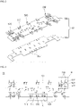
- FIG. 1 is a partially exploded perspective view of a battery pack according to an embodiment of the present disclosure
- FIG. 2 is an exploded perspective view of the hybrid circuit board shown in FIG. 1
- FIG. 3 is a plan view of the hybrid circuit board shown in FIG. 2
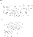
- FIG. 4 is an enlarged plan view of the portion "A" of FIG. 3
- FIG. 5 is an enlarged plan view of the portion "B" of FIG. 3 .
- a battery pack 1 includes a plurality of battery cells 10, a cell frame 20 which aligns and supports the battery cells 10, a plurality of busbars 40, which are electrically connected to the battery cells 10, and a busbar holder 30, which supports the busbars 40.
- the battery pack 1 may further include a hybrid circuit board 50 on which various circuits and components are mounted.
- the busbars 40 may be electrically connected to the hybrid circuit board 50, and the hybrid circuit board 50 may be electrically connected to the outside of the battery pack 1 through a separate connector.
- the battery pack 1 may be referred to as a battery module.
- the battery cells 10 may have a rectangular parallelepiped shape, and a plurality of battery cells 10 may be arranged in a line along a direction (e.g., a predetermined direction). Here, each of the battery cells 10 may be arranged so that their relatively wide plate surfaces face each other.
- the cell frame 20 is provided to align the battery cells 10.
- Each of the battery cells 10 may include a rectangular parallelepiped-shaped case, an electrode assembly accommodated together with an electrolyte in the case, and a cell cap 12 for sealing the case.
- the electrode assembly may be formed by sequentially winding or stacking a negative electrode plate, a separator, and a positive electrode plate.
- a negative electrode active material such as graphite or carbon, may be applied or coated on the negative electrode plate.
- the negative electrode plate may be formed of a metal foil, such as copper, copper alloy, nickel, or nickel alloy.
- An active material such as a transition metal oxide, may be applied or coated on the positive electrode plate.
- the positive electrode plate may be formed of a metal foil, such as aluminum or an aluminum alloy.
- An uncoated region that is, an area to which an active material is not applied, may be formed on the negative electrode plate and the positive electrode plate, respectively.
- a negative electrode tab may be connected to the negative electrode uncoated region, and a positive electrode tab may be connected to the positive electrode uncoated region.
- the negative electrode tab and the positive electrode tab, connected in this way, may be respectively electrically connected to the negative electrode terminal and the positive electrode terminal formed in the cell cap 12.
- the negative and positive electrode terminals on the cell cap 12 are electrically connected to the busbars 40.
- the cell frame 20 includes a pair of end plates 22 that are in contact with the battery cells 10 at both ends along the arrangement direction of the battery cells 10, a pair of side plates 24 coupled orthogonally to the end plates 22, and a top plate 26 coupled to an upper portion of the hybrid circuit board 50.
- a bottom plate of the cell frame 20 is provided on the lower portion of the battery cells 10 to support the battery cells 10 from the lower portion.
- the end plates 22 support the battery cells 10 in the front-rear direction
- the side plates 24 support the battery cells 10 in the left-right direction
- the top plate 26 support the battery cells 10 in the upper direction, respectively.
- the end plate 22, the side plates 24, the top plate 26, and the bottom plate are coupled to one another to form a substantially rectangular parallelepiped frame, and the battery cells 10, the busbar holder 30 and the busbars 40, and the hybrid circuit board 50, are accommodated therein.
- the busbar holder 30 may be seated on top of the cell cap 12 on the basis of FIG. 1 .
- the busbar holder 30 is a substantially rectangular plate, and a plurality of openings (e.g., through holes), through which the positive and negative electrode terminals of the cell cap 12 are exposed, may be formed therein.
- the busbar holder 30 may be made of an insulating material. When the positive electrode terminal and the negative electrode terminal are exposed through the openings formed in the busbar holder 30, the busbar 40 are electrically connected to the exposed positive electrode terminal and the negative electrode terminal.
- the busbar 40 may electrically connect the positive electrode terminal and the negative electrode terminal (e.g., the positive electrode terminal of one of the battery cells 10 to the negative electrode terminal of another one of the battery cells 10).
- the busbar 40 may connect the plurality of battery cells 10 in series and/or in parallel. To this end, a plurality of busbars 40 may be provided.
- the busbars 40 may electrically connect non-adjacent battery cells 10 from among the battery cells 10 arranged in a row.
- the busbars 40 may electrically connect the positive electrode terminal of one battery cell 10 and a positive electrode terminal or a negative electrode terminal of another battery cell 10.
- the busbar 40 may electrically connect the negative electrode terminal of one battery cell 10 and a positive electrode terminal or a negative electrode terminal of another battery cell 10.
- the busbar 40 may be connected to the positive electrode terminal and the negative electrode terminal by welding or the like. Areas other than the busbar 40 and the positive and negative electrode terminals may be insulated by the busbar holder 30.
- the hybrid circuit board 50 is disposed between the busbar(s) 40 and the top plate 26.
- the hybrid circuit board 50 may include a rigid substrate 50a and a flexible substrate 50b.
- the rigid substrate 50a is coupled to the flexible substrate 50b to support the flexible substrate 50b and to reinforce (or improve) rigidity.
- the rigid substrate 50a may be simply formed of a reinforcing material for reinforcement without circuit mounting.
- the rigid substrate 50a may be a printed circuit board (PCB) on which a circuit is mounted. Because the rigid substrate 50a supports the flexible substrate 50b, it may have a shape similar to that of the flexible substrate 50b.
- the rigid substrate 50a may have the same size as the flexible substrate 50b or a slightly smaller size.
- the rigid substrate 50a may have a substantially rectangular shape and may be disposed so that a long side direction coincides with an arrangement direction of the battery cells 10. On the basis of FIG. 1 , the flexible substrate 50b is coupled to the upper portion of the rigid substrate 50a.
- the flexible substrate 50b is a substrate made of a flexible material having lower strength than the rigid substrate 50a.
- the flexible substrate 50b may be (or may be referred to as) a flexible printed circuit assembly (FPCA) or a flexible printed circuit board (FPCB).
- FPCA flexible printed circuit assembly
- FPCB flexible printed circuit board
- various parts (or components or circuits) for measuring state information of the battery cells 10, such as voltages and/or temperatures of the battery cells 10, and various parts (or components or circuits) for controlling and/or managing the battery cells 10, may be mounted.
- the flexible substrate 50b may have a substantially rectangular shape, and a first tab connection portion 510 and a second tab connection portion 520 may be formed at edges thereof in the long side (or length) direction.
- a substrate tab 530 is connected to the first tab connection portion 510 and the second tab connection portion 520, respectively.
- the flexible substrate 50b may be disposed such that the long side direction coincides with an arrangement direction of the battery cells 10. Because the flexible substrate 50b is to be connected to the busbars 40, the flexible substrate 50b should cover a certain portion (or size) or more of the area of the busbar holder 30.
- the flexible substrate 50b may have a different size than the busbar holder 30 but may have a size sufficient to be at least adjacent to the installation area for the busbars 40 for a smooth connection with the busbars 40.
- the flexible substrate 50b may have a short side (or width) length corresponding to an interval between the left busbars 40 and the right busbars 40 shown in FIG. 1 .
- the flexible substrate 50b may have a long side length equal to the sum of the widths of the left or right busbars 40 in the arrangement direction of the battery cells 10.
- first and second tab connection portions 510 and 520 may be formed on the edges of the flexible substrate 50b in the longitudinal (or long side or length) direction.
- first tab connection portion 510 and the second tab connection portion 520 may also be formed on the edges of the flexible substrate 50b in the short side (or width) direction.
- the first tab connection portion 510 is a portion of the flexible substrate 50b to which the substrate tab 530, which is electrically connected to the busbar 40, is connected.
- the first tab connection portion 510 may be formed to have a size the same as or slightly larger than the size of a portion to which the substrate tab 530 is welded (hereinafter, referred to as a first welding portion).
- a first shape portion 512 that is cut in an approximately water-droplet shape may be formed in the flexible substrate 50b at both sides of the first tab connection portion 510.
- the first shape portion 512 is concavely cut inwardly from an edge of the flexible substrate 50b in the long side direction and is provided on both sides of the first tab connection portion 510. Because the first tab connection portion 510 is a free end due to the first shape portion 512 and is a flexible material, the first tab connection portion 510 can move with a degree of freedom in the vertical, horizontal, and horizontal directions, on the basis of FIG. 1 .
- the first tab connection portion 510 is connected to the busbar 40 by the substrate tab 530, and the busbar 40 is connected to the cell cap 12. Therefore, even if vibration is transmitted to the first tab connection portion 510 when swelling occurs in the battery cell 10, the swelling can be absorbed by the first shape portion 512.
- the first shape portion 512 for absorbing swelling may be implemented in a different shape depending on a distance from the busbar 40 or interference with the busbar holder 30.
- the second tab connection portion 520 to which the substrate tab 530 is connected, may be formed on the flexible substrate 50b, and a second shape portion 522 having an approximately 'S' shape may be provided.
- the second shape portion 522 includes an extension portion 522a extending in a straight line from one end of the edge of the flexible substrate 50b, a curved portion 522b integrally formed with the extension portion 522a and having an approximately 'S' curve shape, and a connection portion 522c formed integrally with the curved portion 522b and formed in a straight line to be connected to the second tab connection portion 520.
- the second tab connection portion 520 to which the substrate tab 530 is connected, is formed at an end of the connection portion 522c of the second shape portion 522.
- the second shape portion 522 has a width smaller than the size of the second tab connection portion 520 and is spaced apart from the end of the flexible substrate 50b. Therefore, because the second tab connection portion 520 becomes a free end due to the second shape portion 522 and is a flexible material, the second tab connection portion 520 can move with a degree of freedom in the vertical, horizontal, left, and right directions, on the basis of FIG. 1 . Accordingly, swelling of the battery cells 10 may also be absorbed by the second shape portion 522.
- the first tab connection portion 510 should be able to flow with a degree of freedom (e.g., a predetermined degree of freedom). Accordingly, when the rigid substrate 50a is coupled to the flexible substrate 50b, the extended length of the portion of the rigid substrate 50a supporting the first tab connection portion 510 (hereinafter, referred to as a support portion 50a') may be smaller than the extended length of the first tab connection portion 510. As used herein, the extended length is a distance at which the first tab connection portion 510 protrudes from the end of the flexible substrate 50b. In other embodiments, the support portion 50a' of the rigid substrate 50a may not be fixed to the first tab connection portion 510. For example, the extended length of the support portion 50a' may be the same as the extended length of the first tab connection portion 510.
- a degree of freedom e.g., a predetermined degree of freedom
- the second tab connection portion 520 should be able to flow with a degree of freedom (e.g., a predetermined degree of freedom).
- the rigid substrate 50a may be shaped so as not to support a portion of the flexible substrate 50b where the second tab connection portion 520 is formed.
- the rigid substrate 50a may be shaped such that the portion where the second tab connection portion 520 is formed is empty.
- FIG. 2 shows an embodiment in which the portion of the rigid substrate 50a corresponding to the second tab connection portion 520 of the flexible substrate 50b is empty.
- the substrate tab 530 is a metal tab for connecting the first tab connection portion 510 and the second tab connection portion 520 to the busbars 40 , respectively.
- the substrate tab 530 may be made of a nickel material.
- the substrate tab 530 may include a plurality of substrate tabs, and they may have a substantially rectangular shape. One end of the substrate tab 530 is coupled to the first tab connection portion 510 or the second tab connection portion 520, and the other end thereof extends to the outside of the first tab connection portion 510 or the second tab connection portion 520. Part or all of a region of the substrate tab 530, except for one end thereof, may be coupled to the busbars 40.
- first welding portion 532 One end of the substrate tab 530 that is coupled to the first tab connection portion 510 or the second tab connection portion 520 may be defined as a first welding portion 532, and the remaining portion may be defined as a second welding portion 534.
- first welding portion 532 may be connected to the first tab connection portion 510 or the second tab connection portion 520 by soldering
- the second welding portion 534 may be connected to the busbar 40 by laser welding.
- both the first welding portion 532 and the second welding portion 534 may be welded by ultrasonic welding or laser welding.
- first welding portion 532 and the second welding portion 534 are physically coupled (e.g., are integrally formed) and electrically connected to the first tab connection portion 510, the second tab connection portion 520, or the busbars 40, the coupling method is not limited.
- first welding portion 532 and the second welding portion 534 may have different shapes than those shown in the drawings, which are provided by way of example. In other words, the shapes if the first welding portion 532 and the second welding portion 534 are not limited thereto.
- the flexible substrate 50b and the busbar 40 are electrically connected by the substrate tab 530, a bolting process and bolting parts for connecting the substrate and the busbar holder 30 may be omitted.
- tox clinching which is a type of riveting process for bonding dissimilar metals, for connecting a substrate and the busbars 40 may be omitted. Therefore, the assembly quality is improved, the quality can be stabilized, and the cost can be reduced by the omission of parts.
- FIG. 6A is a cross-sectional view schematically illustrating a state in which a conventional busbar holder and a rigid circuit board are coupled.
- FIG. 6B is a cross-sectional view schematically illustrating a coupling state between a busbar holder and a hybrid circuit board of a battery pack according to an embodiment of the present disclosure.
- a busbar holder (b) is disposed on a cell cap (a), a rigid circuit board (e) is placed on the busbar holder (b), and the rigid circuit board (e) is then fixed to the busbar holder (b) by using an insert nut (c) and a bolt (d). Thereafter, a top plate (f) is fastened on the rigid circuit board (e).
- a height ranging from the top plate (f) to the head of the bolt (d) may be about 2.4 mm, and a height ranging from the head of the bolt (d) to the bottom of the busbar holder (b) may be about 13 mm (hereinafter, the sum of the two heights is defined as a module height). That is, in the conventional structure, the module height is about 15.4 mm.
- the coupling structure is, according to an embodiment, as shown in FIG. 6B .
- a busbar holder 30 is placed on a cell cap 12, and a hybrid circuit board 50 on which components are mounted is placed on the busbar holder 30.
- a top plate 26 is disposed on the hybrid circuit board 50.
- a height ranging from the top plate 26 to the top end of a component mounted on the hybrid circuit board 50 may be about 2.4 mm
- a height ranging from the top end of the component mounted on the hybrid circuit board 50 to the bottom of the busbar holder 30 may be about 8 mm. Therefore, the module height according an embodiment of the present disclosure is about 10.4 mm, and thus, the module height can be greatly reduced compared to the conventional structure shown in FIG. 6A .
- FIG. 7 is a plan view of a hybrid circuit board according to another embodiment of the present disclosure
- FIG. 8 is an enlarged perspective view of the portion "C" of FIG. 7
- FIG. 9 is an enlarged bottom perspective view of portions of the portion "C" shown in FIG. 8 .
- a plurality of first tab connection portions 510 and a sensor connection portion 540 may be formed on a flexible substrate 50b'.
- the first tab connection portion 510 may have the same shape and structure as that shown in FIG. 4 .
- the substrate tab 530 may be formed in a rectangular shape without a separate welding portion. A similar configuration of the substrate tab 530 may also be applied to the embodiment shown in FIG. 4 .
- the sensor connection portion 540 may extend from one edge of the flexible substrate 50b' in an approximately 'S' shape.
- a foam pad 542 on which a temperature sensor 544 is mounted may be coupled to the extended (or distal) end of the sensor connection portion 540.
- the foam pad 542 has a hexahedron shape having a thickness (e.g., a predetermined thickness), and an accommodation space in which the temperature sensor 544 is mounted may be formed on (or in) the foam pad 542.
- the foam pad 542 may be formed to surround (e.g., to surround in a plan view or to extend around a periphery of) the temperature sensor 544.
- a metal tab 546 see, e.g., FIG.
- the metal tab 546 may be made of an aluminum material.
- the temperature of the battery cell 10 may be measured by attaching the metal tab 546 to the surface of the battery cell 10 by using a double-sided tape or the like. Accordingly, the shape and length of the sensor connection portion 540 may vary depending on a position to which the metal tab 546 is attached.
- the processes and parts for connecting a temperature sensor to a board with a separate connector and wire, and welding the temperature sensor to a battery cell and installing the same may be omitted. Accordingly, the cost can be reduced and the process can be simplified due to omission of parts.
- the above-described sensor connection portion 540 may also be applied to the hybrid circuit board 50 shown in FIG. 3 .
- components are not mounted on the edge of a flexible board having a swelling absorption structure formed thereon.
- the component is mounted on a portion that is less affected by swelling and is supported by a rigid substrate.
- components may be disposed at a central portion spaced apart from the edge along the longitudinal direction of the flexible substrate.
- the rigidity of the substrate can be reinforced.
- the hybrid circuit board according to embodiments of the present disclosure has a swelling absorption structure and can be connected to the busbar without a bolting process, and thus, a separate swelling absorption structure may be omitted and the busbar connection structure can be simplified. Accordingly, a cause of increased height of a battery pack is eliminated, thereby enabling a battery pack having a reduced or minimum height.
Landscapes
- Chemical & Material Sciences (AREA)
- Chemical Kinetics & Catalysis (AREA)
- Electrochemistry (AREA)
- General Chemical & Material Sciences (AREA)
- Engineering & Computer Science (AREA)
- Microelectronics & Electronic Packaging (AREA)
- Manufacturing & Machinery (AREA)
- Battery Mounting, Suspending (AREA)
- Connection Of Batteries Or Terminals (AREA)
Abstract
Description
- Aspects of embodiments of the present disclosure relate to a hybrid circuit board and a battery pack having the same.
- Generally, a battery pack includes a plurality of battery cells, a busbar electrically connecting the battery cells to the outside (e.g., to an outside load), and a rigid circuit board that is electrically connected to the busbar and on which various circuits and components are mounted.
- The busbar is mounted on the rigid circuit board by using bolts and insert nuts, which may cause the height of the battery pack to be increased. In addition, to absorb swelling of a battery cell, a separate terminal having a swelling-absorption structure should be bolted between the rigid circuit board and the battery cell. Further, a tox clinching process should be used for connecting the busbar, and thus, there are problems in that the structure of the battery pack and battery module becomes complicated, the costs increase, and it may be difficult to reduce the height of the module.
- The above information disclosed in this Background section is only for enhancement of understanding of the background of the described technology, and therefore, it may contain information that does not form the prior art that is already known to a person of ordinary skill in the art.
- The present disclosure provides a hybrid circuit board having a rigidity-reinforcement and swelling-absorption structure and a battery pack having the same.
- The present disclosure also provides a hybrid circuit board having a simple busbar connection structure that avoids increasing the height of a module, and a battery pack having the same.
- A hybrid circuit board according to an embodiment of the present disclosure includes: a flexible substrate including (or made of) a flexible material that is configured to be electrically connected to a plurality of busbars, which electrically connect a plurality of battery cells; and a rigid substrate including (or made of) a rigid material that is coupled to the flexible substrate to support the flexible substrate.
- The flexible substrate may include a plurality of tab connection portions along an edge thereof, and a substrate tab may be electrically connected to each of the tab connection portions and the busbars.
- The flexible substrate may have a first shape portion at both sides of the tab connection portion, and the first shape may be concavely cut inwardly from a corresponding edge of the flexible substrate.
- The flexible substrate may have a second shape portion extending from a corresponding edge of the flexible substrate in an 'S' shape and integrally formed with the tab connection portion.
- One end of the substrate tab may be soldered to the tab connection portion, and the other end thereof may be laser-welded to the busbar.
- The flexible circuit board may further include a sensor connection portion extending in an 'S' shape from one of the edges of the flexible substrate. The sensor connection portion may include a temperature sensor configured to measure the temperature of at least one of the battery cells, a foam pad accommodating the temperature sensor, and a metal tab coupled to the foam pad and connected to the temperature sensor and the at least one battery cell.
- A battery pack, according to an embodiment of the present disclosure, includes: a plurality of battery cells arranged in one direction, each of the battery cells including a positive electrode terminal and a negative electrode terminal; a plurality of busbars electrically connected to the positive electrode terminal or the negative electrode terminal of each of the battery cells; and a hybrid circuit board including a rigid substrate and a flexible substrate that is coupled to the rigid substrate and is electrically connected to the busbars. The rigid substrate is arranged between the busbars and the flexible substrate.
- The flexible substrate may include a plurality of tab connection portions along edges thereof, and a substrate tab may be electrically connected to each of the tab connection portions and the busbar.
- The flexible substrate may have a first shape portion formed at both sides of the tab connection portion, and the first shape may be concavely cut inwardly from a corresponding edge of the flexible substrate.
- The flexible substrate may have a second shape portion extending from one of the edges of the flexible substrate in an 'S' shape and integrally formed with the tab connection portion.
- One end of the substrate tab may be soldered to the tab connection portion, and the other end thereof may be laser-welded to the busbar.
- The flexible substrate may include a sensor connection portion extending in an 'S' shape from one of the edges of the flexible substrate. The sensor connection portion may include a temperature sensor configured to measure the temperature of at least one of the battery cells, a foam pad accommodating the temperature sensor, and a metal tab coupled to the foam pad and connected to the temperature sensor and the battery cell.
- At least some of the above features that accord with the invention and other features according to the invention are set out in the claims.
-
-
FIG. 1 is a partially exploded perspective view of a battery pack according to an embodiment of the present disclosure. -
FIG. 2 is an exploded perspective view of the hybrid circuit board shown inFIG. 1 . -
FIG. 3 is a plan view of the hybrid circuit board shown inFIG. 2 . -
FIG. 4 is an enlarged plan view of the portion "A" ofFIG. 3 . -
FIG. 5 is an enlarged plan view of the portion "B" ofFIG. 3 . -
FIG. 6A is a cross-sectional view schematically illustrating a state in which a conventional busbar holder and a rigid circuit board are coupled. -
FIG. 6B is a cross-sectional view schematically illustrating a coupling state between a busbar holder and a hybrid circuit board of a battery pack according to an embodiment of the present disclosure. -
FIG. 7 is a plan view of a hybrid circuit board according to another embodiment of the present disclosure. -
FIG. 8 is an enlarged perspective view of the portion "C" ofFIG. 7 . -
FIG. 9 is an enlarged bottom perspective view of portions of the portion "C" shown inFIG. 8 . - Embodiments of the present disclosure are provided to assist in explaining the present disclosure, and the following embodiments may be embodied in many different forms and should not be construed as being limited to the embodiments set forth herein. The scope of the invention is defined by the claims. Rather, these embodiments are provided to convey the aspects and features of the present disclosure to a person skilled in the art.
- In addition, in the accompanying drawings, sizes or thicknesses of various components may be exaggerated for brevity and clarity. Like numbers refer to like elements throughout. As used herein, the term "and/or" includes any and all combinations of one or more of the associated listed items. In addition, it will be understood that when an element A is referred to as being "connected to" an element B, the element A can be directly connected to the element B or an intervening element C may be present therebetween such that the element A and the element B are indirectly connected to each other.
- The terminology used herein is for the purpose of describing particular embodiments and is not intended to be limiting of the disclosure. As used herein, the singular forms are intended to include the plural forms as well, unless the context clearly indicates otherwise. It will be further understood that the terms that the terms "have," "comprise," or "include" and variations thereof, such as "having," "comprising," or "including," when used in this specification, specify the presence of stated features, numbers, steps, operations, elements, and/or components but do not preclude the presence or addition of one or more other features, numbers, steps, operations, elements, components, and/or groups thereof.
- It will be understood that, although the terms first, second, etc. may be used herein to describe various members, elements, regions, layers, and/or sections, these members, elements, regions, layers, and/or sections should not be limited by these terms. These terms are only used to distinguish one member, element, region, layer and/or section from another. Thus, for example, a first member, a first element, a first region, a first layer, and/or a first section discussed below could be termed a second member, a second element, a second region, a second layer, and/or a second section without departing from the teachings of the present disclosure.
- Spatially relative terms, such as "beneath," "below," "lower," "above," "upper," and the like, may be used herein for ease of description to describe one element or feature's relationship to another element(s) or feature(s) as illustrated in the figures. It will be understood that the spatially relative terms are intended to encompass different orientations of the device in use or operation in addition to the orientation depicted in the figures. For example, if the element or feature in the figures is turned over, elements described as "below" or "beneath" other elements or features would then be oriented "on" or "above" the other elements or features. Thus, the exemplary term "below" can encompass both an orientation of above and below, etc. Further, the use of "may" when describing embodiments of the present disclosure relates to "one or more embodiments of the present disclosure." Expressions, such as "at least one of," when preceding a list of elements, modify the entire list of elements and do not modify the individual elements of the list. As used herein, the terms "use," "using," and "used" may be considered synonymous with the terms "utilize," "utilizing," and "utilized," respectively. As used herein, the terms "substantially," "about," and similar terms are used as terms of approximation and not as terms of degree, and are intended to account for the inherent variations in measured or calculated values that would be recognized by those of ordinary skill in the art.
- Hereinafter, a hybrid circuit board and a battery pack having the same according to embodiments of the present disclosure will be described, in detail, with reference to the accompanying drawings.
-
FIG. 1 is a partially exploded perspective view of a battery pack according to an embodiment of the present disclosure,FIG. 2 is an exploded perspective view of the hybrid circuit board shown inFIG. 1 ,FIG. 3 is a plan view of the hybrid circuit board shown inFIG. 2 ,FIG. 4 is an enlarged plan view of the portion "A" ofFIG. 3 , andFIG. 5 is an enlarged plan view of the portion "B" ofFIG. 3 . - As shown in
FIG. 1 , abattery pack 1 according to an embodiment of the present disclosure includes a plurality ofbattery cells 10, acell frame 20 which aligns and supports thebattery cells 10, a plurality ofbusbars 40, which are electrically connected to thebattery cells 10, and abusbar holder 30, which supports thebusbars 40. Thebattery pack 1 may further include ahybrid circuit board 50 on which various circuits and components are mounted. Thebusbars 40 may be electrically connected to thehybrid circuit board 50, and thehybrid circuit board 50 may be electrically connected to the outside of thebattery pack 1 through a separate connector. Thebattery pack 1 may be referred to as a battery module. - The
battery cells 10 may have a rectangular parallelepiped shape, and a plurality ofbattery cells 10 may be arranged in a line along a direction (e.g., a predetermined direction). Here, each of thebattery cells 10 may be arranged so that their relatively wide plate surfaces face each other. Thecell frame 20 is provided to align thebattery cells 10. Each of thebattery cells 10 may include a rectangular parallelepiped-shaped case, an electrode assembly accommodated together with an electrolyte in the case, and acell cap 12 for sealing the case. - The electrode assembly may be formed by sequentially winding or stacking a negative electrode plate, a separator, and a positive electrode plate. A negative electrode active material, such as graphite or carbon, may be applied or coated on the negative electrode plate. The negative electrode plate may be formed of a metal foil, such as copper, copper alloy, nickel, or nickel alloy. An active material, such as a transition metal oxide, may be applied or coated on the positive electrode plate. The positive electrode plate may be formed of a metal foil, such as aluminum or an aluminum alloy. An uncoated region, that is, an area to which an active material is not applied, may be formed on the negative electrode plate and the positive electrode plate, respectively. A negative electrode tab may be connected to the negative electrode uncoated region, and a positive electrode tab may be connected to the positive electrode uncoated region. The negative electrode tab and the positive electrode tab, connected in this way, may be respectively electrically connected to the negative electrode terminal and the positive electrode terminal formed in the
cell cap 12. The negative and positive electrode terminals on thecell cap 12 are electrically connected to thebusbars 40. - The
cell frame 20 includes a pair ofend plates 22 that are in contact with thebattery cells 10 at both ends along the arrangement direction of thebattery cells 10, a pair ofside plates 24 coupled orthogonally to theend plates 22, and atop plate 26 coupled to an upper portion of thehybrid circuit board 50. On the basis ofFIG. 1 , a bottom plate of thecell frame 20 is provided on the lower portion of thebattery cells 10 to support thebattery cells 10 from the lower portion. On the basis ofFIG. 1 , theend plates 22 support thebattery cells 10 in the front-rear direction, theside plates 24 support thebattery cells 10 in the left-right direction, and thetop plate 26 support thebattery cells 10 in the upper direction, respectively. Theend plate 22, theside plates 24, thetop plate 26, and the bottom plate (not shown) are coupled to one another to form a substantially rectangular parallelepiped frame, and thebattery cells 10, thebusbar holder 30 and thebusbars 40, and thehybrid circuit board 50, are accommodated therein. - The
busbar holder 30 may be seated on top of thecell cap 12 on the basis ofFIG. 1 . Thebusbar holder 30 is a substantially rectangular plate, and a plurality of openings (e.g., through holes), through which the positive and negative electrode terminals of thecell cap 12 are exposed, may be formed therein. Thebusbar holder 30 may be made of an insulating material. When the positive electrode terminal and the negative electrode terminal are exposed through the openings formed in thebusbar holder 30, thebusbar 40 are electrically connected to the exposed positive electrode terminal and the negative electrode terminal. - The
busbar 40 may electrically connect the positive electrode terminal and the negative electrode terminal (e.g., the positive electrode terminal of one of thebattery cells 10 to the negative electrode terminal of another one of the battery cells 10). Thebusbar 40 may connect the plurality ofbattery cells 10 in series and/or in parallel. To this end, a plurality ofbusbars 40 may be provided. In one example, thebusbars 40 may electrically connectnon-adjacent battery cells 10 from among thebattery cells 10 arranged in a row. In other embodiments, thebusbars 40 may electrically connect the positive electrode terminal of onebattery cell 10 and a positive electrode terminal or a negative electrode terminal of anotherbattery cell 10. In addition, thebusbar 40 may electrically connect the negative electrode terminal of onebattery cell 10 and a positive electrode terminal or a negative electrode terminal of anotherbattery cell 10. Thebusbar 40 may be connected to the positive electrode terminal and the negative electrode terminal by welding or the like. Areas other than thebusbar 40 and the positive and negative electrode terminals may be insulated by thebusbar holder 30. Thehybrid circuit board 50 is disposed between the busbar(s) 40 and thetop plate 26. - As shown in
FIG. 2 , thehybrid circuit board 50 may include arigid substrate 50a and aflexible substrate 50b. - The
rigid substrate 50a is coupled to theflexible substrate 50b to support theflexible substrate 50b and to reinforce (or improve) rigidity. Therigid substrate 50a may be simply formed of a reinforcing material for reinforcement without circuit mounting. In other embodiments, therigid substrate 50a may be a printed circuit board (PCB) on which a circuit is mounted. Because therigid substrate 50a supports theflexible substrate 50b, it may have a shape similar to that of theflexible substrate 50b. Therigid substrate 50a may have the same size as theflexible substrate 50b or a slightly smaller size. Therigid substrate 50a may have a substantially rectangular shape and may be disposed so that a long side direction coincides with an arrangement direction of thebattery cells 10. On the basis ofFIG. 1 , theflexible substrate 50b is coupled to the upper portion of therigid substrate 50a. - The
flexible substrate 50b is a substrate made of a flexible material having lower strength than therigid substrate 50a. Theflexible substrate 50b may be (or may be referred to as) a flexible printed circuit assembly (FPCA) or a flexible printed circuit board (FPCB). In theflexible substrate 50b, various parts (or components or circuits) for measuring state information of thebattery cells 10, such as voltages and/or temperatures of thebattery cells 10, and various parts (or components or circuits) for controlling and/or managing thebattery cells 10, may be mounted. - As shown in
FIGS. 2 and 3 , theflexible substrate 50b may have a substantially rectangular shape, and a firsttab connection portion 510 and a secondtab connection portion 520 may be formed at edges thereof in the long side (or length) direction. Asubstrate tab 530 is connected to the firsttab connection portion 510 and the secondtab connection portion 520, respectively. Theflexible substrate 50b may be disposed such that the long side direction coincides with an arrangement direction of thebattery cells 10. Because theflexible substrate 50b is to be connected to thebusbars 40, theflexible substrate 50b should cover a certain portion (or size) or more of the area of thebusbar holder 30. Theflexible substrate 50b may have a different size than thebusbar holder 30 but may have a size sufficient to be at least adjacent to the installation area for thebusbars 40 for a smooth connection with thebusbars 40. For example, theflexible substrate 50b may have a short side (or width) length corresponding to an interval between theleft busbars 40 and theright busbars 40 shown inFIG. 1 . In addition, theflexible substrate 50b may have a long side length equal to the sum of the widths of the left orright busbars 40 in the arrangement direction of thebattery cells 10. - As shown in
FIGS. 2 and 3 , a plurality of first and secondtab connection portions flexible substrate 50b in the longitudinal (or long side or length) direction. However, the firsttab connection portion 510 and the secondtab connection portion 520 may also be formed on the edges of theflexible substrate 50b in the short side (or width) direction. - As shown in
FIGS. 2 to 4 , the firsttab connection portion 510 is a portion of theflexible substrate 50b to which thesubstrate tab 530, which is electrically connected to thebusbar 40, is connected. The firsttab connection portion 510 may be formed to have a size the same as or slightly larger than the size of a portion to which thesubstrate tab 530 is welded (hereinafter, referred to as a first welding portion). Afirst shape portion 512 that is cut in an approximately water-droplet shape may be formed in theflexible substrate 50b at both sides of the firsttab connection portion 510. - The
first shape portion 512 is concavely cut inwardly from an edge of theflexible substrate 50b in the long side direction and is provided on both sides of the firsttab connection portion 510. Because the firsttab connection portion 510 is a free end due to thefirst shape portion 512 and is a flexible material, the firsttab connection portion 510 can move with a degree of freedom in the vertical, horizontal, and horizontal directions, on the basis ofFIG. 1 . The firsttab connection portion 510 is connected to thebusbar 40 by thesubstrate tab 530, and thebusbar 40 is connected to thecell cap 12. Therefore, even if vibration is transmitted to the firsttab connection portion 510 when swelling occurs in thebattery cell 10, the swelling can be absorbed by thefirst shape portion 512. Accordingly, damage to the firsttab connection portion 510 or damage to connection portions of thesubstrate tab 530 and thebusbar 40 can be mitigated or prevented. Thefirst shape portion 512 for absorbing swelling may be implemented in a different shape depending on a distance from thebusbar 40 or interference with thebusbar holder 30. - As shown in
FIGS. 2, 3 , and5 , the secondtab connection portion 520, to which thesubstrate tab 530 is connected, may be formed on theflexible substrate 50b, and asecond shape portion 522 having an approximately 'S' shape may be provided. For example, thesecond shape portion 522 includes anextension portion 522a extending in a straight line from one end of the edge of theflexible substrate 50b, acurved portion 522b integrally formed with theextension portion 522a and having an approximately 'S' curve shape, and aconnection portion 522c formed integrally with thecurved portion 522b and formed in a straight line to be connected to the secondtab connection portion 520. The secondtab connection portion 520, to which thesubstrate tab 530 is connected, is formed at an end of theconnection portion 522c of thesecond shape portion 522. In addition, thesecond shape portion 522 has a width smaller than the size of the secondtab connection portion 520 and is spaced apart from the end of theflexible substrate 50b. Therefore, because the secondtab connection portion 520 becomes a free end due to thesecond shape portion 522 and is a flexible material, the secondtab connection portion 520 can move with a degree of freedom in the vertical, horizontal, left, and right directions, on the basis ofFIG. 1 . Accordingly, swelling of thebattery cells 10 may also be absorbed by thesecond shape portion 522. - As such, the first
tab connection portion 510 should be able to flow with a degree of freedom (e.g., a predetermined degree of freedom). Accordingly, when therigid substrate 50a is coupled to theflexible substrate 50b, the extended length of the portion of therigid substrate 50a supporting the first tab connection portion 510 (hereinafter, referred to as asupport portion 50a') may be smaller than the extended length of the firsttab connection portion 510. As used herein, the extended length is a distance at which the firsttab connection portion 510 protrudes from the end of theflexible substrate 50b. In other embodiments, thesupport portion 50a' of therigid substrate 50a may not be fixed to the firsttab connection portion 510. For example, the extended length of thesupport portion 50a' may be the same as the extended length of the firsttab connection portion 510. - In addition, similar to the first
tab connection portion 510, the secondtab connection portion 520 should be able to flow with a degree of freedom (e.g., a predetermined degree of freedom). To this end, therigid substrate 50a may be shaped so as not to support a portion of theflexible substrate 50b where the secondtab connection portion 520 is formed. For example, therigid substrate 50a may be shaped such that the portion where the secondtab connection portion 520 is formed is empty.FIG. 2 shows an embodiment in which the portion of therigid substrate 50a corresponding to the secondtab connection portion 520 of theflexible substrate 50b is empty. - As shown in
FIGS. 4 and 5 , thesubstrate tab 530 is a metal tab for connecting the firsttab connection portion 510 and the secondtab connection portion 520 to thebusbars 40 , respectively. For example, thesubstrate tab 530 may be made of a nickel material. Thesubstrate tab 530 may include a plurality of substrate tabs, and they may have a substantially rectangular shape. One end of thesubstrate tab 530 is coupled to the firsttab connection portion 510 or the secondtab connection portion 520, and the other end thereof extends to the outside of the firsttab connection portion 510 or the secondtab connection portion 520. Part or all of a region of thesubstrate tab 530, except for one end thereof, may be coupled to thebusbars 40. One end of thesubstrate tab 530 that is coupled to the firsttab connection portion 510 or the secondtab connection portion 520 may be defined as afirst welding portion 532, and the remaining portion may be defined as asecond welding portion 534. For example, thefirst welding portion 532 may be connected to the firsttab connection portion 510 or the secondtab connection portion 520 by soldering, and thesecond welding portion 534 may be connected to thebusbar 40 by laser welding. However, both thefirst welding portion 532 and thesecond welding portion 534 may be welded by ultrasonic welding or laser welding. For example, when thefirst welding portion 532 and thesecond welding portion 534 are physically coupled (e.g., are integrally formed) and electrically connected to the firsttab connection portion 510, the secondtab connection portion 520, or thebusbars 40, the coupling method is not limited. In addition, thefirst welding portion 532 and thesecond welding portion 534 may have different shapes than those shown in the drawings, which are provided by way of example. In other words, the shapes if thefirst welding portion 532 and thesecond welding portion 534 are not limited thereto. - As described above, because the
flexible substrate 50b and thebusbar 40 are electrically connected by thesubstrate tab 530, a bolting process and bolting parts for connecting the substrate and thebusbar holder 30 may be omitted. In addition, tox clinching, which is a type of riveting process for bonding dissimilar metals, for connecting a substrate and thebusbars 40 may be omitted. Therefore, the assembly quality is improved, the quality can be stabilized, and the cost can be reduced by the omission of parts. -
FIG. 6A is a cross-sectional view schematically illustrating a state in which a conventional busbar holder and a rigid circuit board are coupled.FIG. 6B is a cross-sectional view schematically illustrating a coupling state between a busbar holder and a hybrid circuit board of a battery pack according to an embodiment of the present disclosure. - As shown in
FIG. 6A , conventionally, a busbar holder (b) is disposed on a cell cap (a), a rigid circuit board (e) is placed on the busbar holder (b), and the rigid circuit board (e) is then fixed to the busbar holder (b) by using an insert nut (c) and a bolt (d). Thereafter, a top plate (f) is fastened on the rigid circuit board (e). For example, a height ranging from the top plate (f) to the head of the bolt (d) may be about 2.4 mm, and a height ranging from the head of the bolt (d) to the bottom of the busbar holder (b) may be about 13 mm (hereinafter, the sum of the two heights is defined as a module height). That is, in the conventional structure, the module height is about 15.4 mm. - In contrast, when the
hybrid circuit board 50 according to embodiments of the present disclosure is applied, the coupling structure is, according to an embodiment, as shown inFIG. 6B . As shown inFIG. 6B , abusbar holder 30 is placed on acell cap 12, and ahybrid circuit board 50 on which components are mounted is placed on thebusbar holder 30. Thereafter, atop plate 26 is disposed on thehybrid circuit board 50. For example, a height ranging from thetop plate 26 to the top end of a component mounted on thehybrid circuit board 50 may be about 2.4 mm, and a height ranging from the top end of the component mounted on thehybrid circuit board 50 to the bottom of thebusbar holder 30 may be about 8 mm. Therefore, the module height according an embodiment of the present disclosure is about 10.4 mm, and thus, the module height can be greatly reduced compared to the conventional structure shown inFIG. 6A . - Hereinafter, a structure of a hybrid circuit board according to another embodiment of the present disclosure will be described, and a detailed description of the same configuration as that of the previous embodiment will be omitted.
-
FIG. 7 is a plan view of a hybrid circuit board according to another embodiment of the present disclosure,FIG. 8 is an enlarged perspective view of the portion "C" ofFIG. 7 , andFIG. 9 is an enlarged bottom perspective view of portions of the portion "C" shown inFIG. 8 . - As shown in
FIG. 7 , in the hybrid circuit board 50' according to another embodiment of the present disclosure, a plurality of firsttab connection portions 510 and asensor connection portion 540 may be formed on aflexible substrate 50b'. Here, the firsttab connection portion 510 may have the same shape and structure as that shown inFIG. 4 . As shown inFIG. 7 , however, thesubstrate tab 530 may be formed in a rectangular shape without a separate welding portion. A similar configuration of thesubstrate tab 530 may also be applied to the embodiment shown inFIG. 4 . - The
sensor connection portion 540 may extend from one edge of theflexible substrate 50b' in an approximately 'S' shape. Afoam pad 542 on which atemperature sensor 544 is mounted may be coupled to the extended (or distal) end of thesensor connection portion 540. Thefoam pad 542 has a hexahedron shape having a thickness (e.g., a predetermined thickness), and an accommodation space in which thetemperature sensor 544 is mounted may be formed on (or in) thefoam pad 542. For example, thefoam pad 542 may be formed to surround (e.g., to surround in a plan view or to extend around a periphery of) thetemperature sensor 544. A metal tab 546 (see, e.g.,FIG. 9 ) electrically connected to thetemperature sensor 544 and connected to thebattery cell 10 or thecell cap 12 may be coupled to the lower portion of thefoam pad 542 in the direction facing thebusbar 40. For example, themetal tab 546 may be made of an aluminum material. The temperature of thebattery cell 10 may be measured by attaching themetal tab 546 to the surface of thebattery cell 10 by using a double-sided tape or the like. Accordingly, the shape and length of thesensor connection portion 540 may vary depending on a position to which themetal tab 546 is attached. By including thesensor connection portion 540, the processes and parts for connecting a temperature sensor to a board with a separate connector and wire, and welding the temperature sensor to a battery cell and installing the same, may be omitted. Accordingly, the cost can be reduced and the process can be simplified due to omission of parts. The above-describedsensor connection portion 540 may also be applied to thehybrid circuit board 50 shown inFIG. 3 . - In the hybrid circuit board according to embodiments of the present disclosure having the above-described structure, components are not mounted on the edge of a flexible board having a swelling absorption structure formed thereon. The component is mounted on a portion that is less affected by swelling and is supported by a rigid substrate. For example, components may be disposed at a central portion spaced apart from the edge along the longitudinal direction of the flexible substrate.
- According to embodiments of the present disclosure, by having both the characteristics of a rigid circuit board and a flexible circuit board, the rigidity of the substrate can be reinforced.
- In addition, the hybrid circuit board according to embodiments of the present disclosure has a swelling absorption structure and can be connected to the busbar without a bolting process, and thus, a separate swelling absorption structure may be omitted and the busbar connection structure can be simplified. Accordingly, a cause of increased height of a battery pack is eliminated, thereby enabling a battery pack having a reduced or minimum height.
- While the foregoing embodiments are only some embodiments for carrying out the present disclosure, which is not limited to these embodiments, it will be understood by a person skilled in the art that various changes in form and details may be made therein without departing from the scope of claims.
Claims (7)
- A hybrid circuit board comprising:a flexible substrate comprising a flexible material, the flexible substrate being electrically connected to a plurality of busbars, the busbars electrically connecting a plurality of battery cells; anda rigid substrate comprising a rigid material, the rigid substrate being coupled to the flexible substrate to support the flexible substrate.
- The hybrid circuit board of claim 1, wherein the flexible substrate comprises a plurality of tab connection portions along an edge thereof, and
wherein a substrate tab is electrically connected to each of the tab connection portions and the busbars. - The hybrid circuit board of claim 2, wherein the flexible substrate has a first shape portion formed at both sides of the tab connection portion, the first shape portion being concavely cut inwardly from the edge of the flexible substrate.
- The hybrid circuit board of claim 3, wherein one end of the substrate tab is soldered to the tab connection portion, and the other end thereof is laser-welded to the busbar.
- The hybrid circuit board of any of claims 2 to 4, wherein the flexible substrate has a second shape portion extending from the edge of the flexible substrate in an 'S' shape and being integrally formed with the tab connection portion.
- The hybrid circuit board of any of claims 2 to 5, further comprising a sensor connection portion extending in an 'S' shape from the edge of the flexible substrate,
wherein the sensor connection portion comprises:a temperature sensor configured to measure a temperature of at least one of the battery cells;a foam pad accommodating the temperature sensor; anda metal tab coupled to the foam pad and connected to the temperature sensor and the at least one of the battery cells. - A battery pack comprising:a plurality of battery cells arranged in one direction, each of the battery cells comprising a positive electrode terminal and a negative electrode terminal;a plurality of busbars electrically connected to the positive electrode terminal or the negative electrode terminal of each of the battery cells; anda hybrid circuit board according to any of claims 1 to 6.
Applications Claiming Priority (1)
| Application Number | Priority Date | Filing Date | Title |
|---|---|---|---|
| KR1020210035284A KR20220130425A (en) | 2021-03-18 | 2021-03-18 | Hybrid circuit board and battery pack having same |
Publications (2)
| Publication Number | Publication Date |
|---|---|
| EP4071904A1 true EP4071904A1 (en) | 2022-10-12 |
| EP4071904B1 EP4071904B1 (en) | 2025-08-13 |
Family
ID=80820112
Family Applications (1)
| Application Number | Title | Priority Date | Filing Date |
|---|---|---|---|
| EP22162941.3A Active EP4071904B1 (en) | 2021-03-18 | 2022-03-18 | Hybrid circuit board and battery pack having same |
Country Status (5)
| Country | Link |
|---|---|
| US (1) | US12610468B2 (en) |
| EP (1) | EP4071904B1 (en) |
| KR (1) | KR20220130425A (en) |
| CN (1) | CN115119396B (en) |
| PL (1) | PL4071904T3 (en) |
Cited By (1)
| Publication number | Priority date | Publication date | Assignee | Title |
|---|---|---|---|---|
| EP4261980A3 (en) * | 2022-03-23 | 2024-02-21 | Samsung SDI Co., Ltd. | Battery pack |
Families Citing this family (8)
| Publication number | Priority date | Publication date | Assignee | Title |
|---|---|---|---|---|
| JP2024080398A (en) * | 2022-12-02 | 2024-06-13 | 日本メクトロン株式会社 | Voltage monitoring module and battery unit |
| KR20250040219A (en) * | 2023-09-15 | 2025-03-24 | 삼성에스디아이 주식회사 | Battery module |
| KR20250073703A (en) * | 2023-11-20 | 2025-05-27 | 삼성에스디아이 주식회사 | Temperature measurement apparatus and battery module including the same |
| KR20250085175A (en) * | 2023-12-05 | 2025-06-12 | 삼성에스디아이 주식회사 | Busbar holder assembly, battery pack including the same and method for manufacturing busbar holder assembly |
| KR20250107639A (en) * | 2024-01-05 | 2025-07-14 | 삼성에스디아이 주식회사 | Rechargeable battery module |
| KR20250176470A (en) * | 2024-06-12 | 2025-12-19 | 주식회사 엘지에너지솔루션 | Battery pack and vehicle including the same |
| KR20250179455A (en) | 2024-06-21 | 2025-12-30 | 한국단자공업 주식회사 | cover assembly of battery module |
| KR20260020721A (en) | 2024-08-05 | 2026-02-12 | 한국단자공업 주식회사 | Electrical connecting apparatus for battery |
Citations (4)
| Publication number | Priority date | Publication date | Assignee | Title |
|---|---|---|---|---|
| US20190027731A1 (en) * | 2017-07-24 | 2019-01-24 | Molex, Llc | Battery connection module |
| US20190088912A1 (en) * | 2017-09-20 | 2019-03-21 | Molex, Llc | Battery connection module |
| WO2020105400A1 (en) * | 2018-11-22 | 2020-05-28 | 株式会社オートネットワーク技術研究所 | Connection module |
| WO2020105399A1 (en) * | 2018-11-22 | 2020-05-28 | 株式会社オートネットワーク技術研究所 | Connection module |
Family Cites Families (11)
| Publication number | Priority date | Publication date | Assignee | Title |
|---|---|---|---|---|
| JP2007266067A (en) | 2006-03-27 | 2007-10-11 | Mitsumi Electric Co Ltd | Flex / rigid board, secondary battery protection module, battery pack, and flex / rigid board manufacturing method |
| US20140120401A1 (en) | 2012-10-30 | 2014-05-01 | Samsung Sdi Co., Ltd. | Connecting structure between circuit boards and battery pack having the same |
| JP6171605B2 (en) | 2013-06-18 | 2017-08-02 | 株式会社デンソー | Battery unit |
| CN205861226U (en) | 2016-08-12 | 2017-01-04 | 泰科电子(上海)有限公司 | Temperature measuring equipment, electric appliance component and battery bag |
| US10749161B2 (en) * | 2016-09-23 | 2020-08-18 | Artisan Vehicle Systems Inc. | Unified connection array for battery module |
| JP6535309B2 (en) | 2016-09-26 | 2019-06-26 | 矢崎総業株式会社 | Battery monitoring unit |
| EP3316384B1 (en) * | 2016-10-25 | 2019-02-20 | Samsung SDI Co., Ltd. | Battery module with a fixing for a temperature sensitive element |
| EP3565022B1 (en) * | 2016-12-27 | 2021-03-10 | Yura Corporation Co., Ltd. | Flexible circuit board and frame assembly including same |
| CN109524608B (en) | 2017-09-20 | 2022-02-11 | 莫列斯有限公司 | Battery connection module |
| KR102017674B1 (en) | 2017-10-11 | 2019-09-04 | 주식회사 아이티엠반도체 | Battery protection package and methods of fabricating the same |
| CN111952490B (en) * | 2019-05-17 | 2022-12-02 | 莫仕连接器(成都)有限公司 | Battery connection module and battery device |
-
2021
- 2021-03-18 KR KR1020210035284A patent/KR20220130425A/en active Pending
-
2022
- 2022-03-14 US US17/654,745 patent/US12610468B2/en active Active
- 2022-03-18 PL PL22162941.3T patent/PL4071904T3/en unknown
- 2022-03-18 CN CN202210270944.5A patent/CN115119396B/en active Active
- 2022-03-18 EP EP22162941.3A patent/EP4071904B1/en active Active
Patent Citations (4)
| Publication number | Priority date | Publication date | Assignee | Title |
|---|---|---|---|---|
| US20190027731A1 (en) * | 2017-07-24 | 2019-01-24 | Molex, Llc | Battery connection module |
| US20190088912A1 (en) * | 2017-09-20 | 2019-03-21 | Molex, Llc | Battery connection module |
| WO2020105400A1 (en) * | 2018-11-22 | 2020-05-28 | 株式会社オートネットワーク技術研究所 | Connection module |
| WO2020105399A1 (en) * | 2018-11-22 | 2020-05-28 | 株式会社オートネットワーク技術研究所 | Connection module |
Cited By (1)
| Publication number | Priority date | Publication date | Assignee | Title |
|---|---|---|---|---|
| EP4261980A3 (en) * | 2022-03-23 | 2024-02-21 | Samsung SDI Co., Ltd. | Battery pack |
Also Published As
| Publication number | Publication date |
|---|---|
| CN115119396B (en) | 2026-04-28 |
| US12610468B2 (en) | 2026-04-21 |
| PL4071904T3 (en) | 2026-05-04 |
| US20220304158A1 (en) | 2022-09-22 |
| CN115119396A (en) | 2022-09-27 |
| EP4071904B1 (en) | 2025-08-13 |
| KR20220130425A (en) | 2022-09-27 |
Similar Documents
| Publication | Publication Date | Title |
|---|---|---|
| EP4071904B1 (en) | Hybrid circuit board and battery pack having same | |
| US12211975B2 (en) | Battery module having connector mounted on FPCB, and battery pack and vehicle comprising same | |
| EP3783687B1 (en) | Battery module having structure in which energy density is improved, and battery pack and vehicle comprising same | |
| KR101252413B1 (en) | Battery module and manufacturing method of battery module | |
| US9640790B2 (en) | Middle or large-sized battery module | |
| US20120019061A1 (en) | Battery module, battery system and electric vehicle | |
| JP2018055843A (en) | Battery monitoring unit | |
| JP7419292B2 (en) | bus bar module | |
| JP7418375B2 (en) | bus bar module | |
| CN113519086A (en) | Busbars and Battery Modules Using Busbars | |
| JP7418374B2 (en) | bus bar module | |
| CN114051675B (en) | Wiring module and power storage module | |
| JP2008204982A (en) | Capacitor unit | |
| EP3975325A2 (en) | Battery module and battery pack including the same | |
| JP2019135687A (en) | Power storage module | |
| JP2019186038A (en) | Battery pack | |
| US12506227B2 (en) | Wiring module | |
| US11876249B2 (en) | Conductive module | |
| EP3923391A1 (en) | Battery module | |
| KR102951081B1 (en) | Battery module | |
| US20240072350A1 (en) | Battery pack | |
| US20260020161A1 (en) | Wire harness | |
| US20230020679A1 (en) | Power storage device | |
| US20250293399A1 (en) | Power storage cell and method for manufacturing the same | |
| US20250266549A1 (en) | Vehicle |
Legal Events
| Date | Code | Title | Description |
|---|---|---|---|
| PUAI | Public reference made under article 153(3) epc to a published international application that has entered the european phase |
Free format text: ORIGINAL CODE: 0009012 |
|
| STAA | Information on the status of an ep patent application or granted ep patent |
Free format text: STATUS: REQUEST FOR EXAMINATION WAS MADE |
|
| 17P | Request for examination filed |
Effective date: 20220318 |
|
| AK | Designated contracting states |
Kind code of ref document: A1 Designated state(s): AL AT BE BG CH CY CZ DE DK EE ES FI FR GB GR HR HU IE IS IT LI LT LU LV MC MK MT NL NO PL PT RO RS SE SI SK SM TR |
|
| GRAP | Despatch of communication of intention to grant a patent |
Free format text: ORIGINAL CODE: EPIDOSNIGR1 |
|
| STAA | Information on the status of an ep patent application or granted ep patent |
Free format text: STATUS: GRANT OF PATENT IS INTENDED |
|
| INTG | Intention to grant announced |
Effective date: 20250311 |
|
| GRAS | Grant fee paid |
Free format text: ORIGINAL CODE: EPIDOSNIGR3 |
|
| GRAA | (expected) grant |
Free format text: ORIGINAL CODE: 0009210 |
|
| STAA | Information on the status of an ep patent application or granted ep patent |
Free format text: STATUS: THE PATENT HAS BEEN GRANTED |
|
| AK | Designated contracting states |
Kind code of ref document: B1 Designated state(s): AL AT BE BG CH CY CZ DE DK EE ES FI FR GB GR HR HU IE IS IT LI LT LU LV MC MK MT NL NO PL PT RO RS SE SI SK SM TR |
|
| REG | Reference to a national code |
Ref country code: GB Ref legal event code: FG4D |
|
| REG | Reference to a national code |
Ref country code: CH Ref legal event code: EP |
|
| REG | Reference to a national code |
Ref country code: DE Ref legal event code: R096 Ref document number: 602022019227 Country of ref document: DE |
|
| REG | Reference to a national code |
Ref country code: IE Ref legal event code: FG4D |
|
| REG | Reference to a national code |
Ref country code: NL Ref legal event code: MP Effective date: 20250813 |
|
| PG25 | Lapsed in a contracting state [announced via postgrant information from national office to epo] |
Ref country code: IS Free format text: LAPSE BECAUSE OF FAILURE TO SUBMIT A TRANSLATION OF THE DESCRIPTION OR TO PAY THE FEE WITHIN THE PRESCRIBED TIME-LIMIT Effective date: 20251213 |
|
| PG25 | Lapsed in a contracting state [announced via postgrant information from national office to epo] |
Ref country code: NO Free format text: LAPSE BECAUSE OF FAILURE TO SUBMIT A TRANSLATION OF THE DESCRIPTION OR TO PAY THE FEE WITHIN THE PRESCRIBED TIME-LIMIT Effective date: 20251113 |
|
| REG | Reference to a national code |
Ref country code: LT Ref legal event code: MG9D |
|
| PG25 | Lapsed in a contracting state [announced via postgrant information from national office to epo] |
Ref country code: PT Free format text: LAPSE BECAUSE OF FAILURE TO SUBMIT A TRANSLATION OF THE DESCRIPTION OR TO PAY THE FEE WITHIN THE PRESCRIBED TIME-LIMIT Effective date: 20251215 |
|
| PG25 | Lapsed in a contracting state [announced via postgrant information from national office to epo] |
Ref country code: FI Free format text: LAPSE BECAUSE OF FAILURE TO SUBMIT A TRANSLATION OF THE DESCRIPTION OR TO PAY THE FEE WITHIN THE PRESCRIBED TIME-LIMIT Effective date: 20250813 |
|
| PG25 | Lapsed in a contracting state [announced via postgrant information from national office to epo] |
Ref country code: HR Free format text: LAPSE BECAUSE OF FAILURE TO SUBMIT A TRANSLATION OF THE DESCRIPTION OR TO PAY THE FEE WITHIN THE PRESCRIBED TIME-LIMIT Effective date: 20250813 Ref country code: NL Free format text: LAPSE BECAUSE OF FAILURE TO SUBMIT A TRANSLATION OF THE DESCRIPTION OR TO PAY THE FEE WITHIN THE PRESCRIBED TIME-LIMIT Effective date: 20250813 |
|
| PG25 | Lapsed in a contracting state [announced via postgrant information from national office to epo] |
Ref country code: GR Free format text: LAPSE BECAUSE OF FAILURE TO SUBMIT A TRANSLATION OF THE DESCRIPTION OR TO PAY THE FEE WITHIN THE PRESCRIBED TIME-LIMIT Effective date: 20251114 |
|
| PG25 | Lapsed in a contracting state [announced via postgrant information from national office to epo] |
Ref country code: SE Free format text: LAPSE BECAUSE OF FAILURE TO SUBMIT A TRANSLATION OF THE DESCRIPTION OR TO PAY THE FEE WITHIN THE PRESCRIBED TIME-LIMIT Effective date: 20250813 |
|
| PG25 | Lapsed in a contracting state [announced via postgrant information from national office to epo] |
Ref country code: LV Free format text: LAPSE BECAUSE OF FAILURE TO SUBMIT A TRANSLATION OF THE DESCRIPTION OR TO PAY THE FEE WITHIN THE PRESCRIBED TIME-LIMIT Effective date: 20250813 |
|
| PG25 | Lapsed in a contracting state [announced via postgrant information from national office to epo] |
Ref country code: BG Free format text: LAPSE BECAUSE OF FAILURE TO SUBMIT A TRANSLATION OF THE DESCRIPTION OR TO PAY THE FEE WITHIN THE PRESCRIBED TIME-LIMIT Effective date: 20250813 |
|
| PG25 | Lapsed in a contracting state [announced via postgrant information from national office to epo] |
Ref country code: RS Free format text: LAPSE BECAUSE OF FAILURE TO SUBMIT A TRANSLATION OF THE DESCRIPTION OR TO PAY THE FEE WITHIN THE PRESCRIBED TIME-LIMIT Effective date: 20251113 |
|
| PG25 | Lapsed in a contracting state [announced via postgrant information from national office to epo] |
Ref country code: ES Free format text: LAPSE BECAUSE OF FAILURE TO SUBMIT A TRANSLATION OF THE DESCRIPTION OR TO PAY THE FEE WITHIN THE PRESCRIBED TIME-LIMIT Effective date: 20250813 |
|
| REG | Reference to a national code |
Ref country code: AT Ref legal event code: MK05 Ref document number: 1825729 Country of ref document: AT Kind code of ref document: T Effective date: 20250813 |
|
| PG25 | Lapsed in a contracting state [announced via postgrant information from national office to epo] |
Ref country code: SM Free format text: LAPSE BECAUSE OF FAILURE TO SUBMIT A TRANSLATION OF THE DESCRIPTION OR TO PAY THE FEE WITHIN THE PRESCRIBED TIME-LIMIT Effective date: 20250813 |
|
| PGFP | Annual fee paid to national office [announced via postgrant information from national office to epo] |
Ref country code: GB Payment date: 20260303 Year of fee payment: 5 |
|
| PG25 | Lapsed in a contracting state [announced via postgrant information from national office to epo] |
Ref country code: DK Free format text: LAPSE BECAUSE OF FAILURE TO SUBMIT A TRANSLATION OF THE DESCRIPTION OR TO PAY THE FEE WITHIN THE PRESCRIBED TIME-LIMIT Effective date: 20250813 |
|
| PGFP | Annual fee paid to national office [announced via postgrant information from national office to epo] |
Ref country code: DE Payment date: 20260305 Year of fee payment: 5 |
|
| PG25 | Lapsed in a contracting state [announced via postgrant information from national office to epo] |
Ref country code: AT Free format text: LAPSE BECAUSE OF FAILURE TO SUBMIT A TRANSLATION OF THE DESCRIPTION OR TO PAY THE FEE WITHIN THE PRESCRIBED TIME-LIMIT Effective date: 20250813 |
|
| PG25 | Lapsed in a contracting state [announced via postgrant information from national office to epo] |
Ref country code: IT Free format text: LAPSE BECAUSE OF FAILURE TO SUBMIT A TRANSLATION OF THE DESCRIPTION OR TO PAY THE FEE WITHIN THE PRESCRIBED TIME-LIMIT Effective date: 20250813 |
|
| PGFP | Annual fee paid to national office [announced via postgrant information from national office to epo] |
Ref country code: HU Payment date: 20260330 Year of fee payment: 5 |
|
| PGFP | Annual fee paid to national office [announced via postgrant information from national office to epo] |
Ref country code: FR Payment date: 20260309 Year of fee payment: 5 |
|
| PG25 | Lapsed in a contracting state [announced via postgrant information from national office to epo] |
Ref country code: CZ Free format text: LAPSE BECAUSE OF FAILURE TO SUBMIT A TRANSLATION OF THE DESCRIPTION OR TO PAY THE FEE WITHIN THE PRESCRIBED TIME-LIMIT Effective date: 20250813 |
|
| PG25 | Lapsed in a contracting state [announced via postgrant information from national office to epo] |
Ref country code: SK Free format text: LAPSE BECAUSE OF FAILURE TO SUBMIT A TRANSLATION OF THE DESCRIPTION OR TO PAY THE FEE WITHIN THE PRESCRIBED TIME-LIMIT Effective date: 20250813 Ref country code: EE Free format text: LAPSE BECAUSE OF FAILURE TO SUBMIT A TRANSLATION OF THE DESCRIPTION OR TO PAY THE FEE WITHIN THE PRESCRIBED TIME-LIMIT Effective date: 20250813 |