EP4071865A1 - Secondary battery, and battery module, battery pack, and device comprising same - Google Patents
Secondary battery, and battery module, battery pack, and device comprising same Download PDFInfo
- Publication number
- EP4071865A1 EP4071865A1 EP21912324.7A EP21912324A EP4071865A1 EP 4071865 A1 EP4071865 A1 EP 4071865A1 EP 21912324 A EP21912324 A EP 21912324A EP 4071865 A1 EP4071865 A1 EP 4071865A1
- Authority
- EP
- European Patent Office
- Prior art keywords
- carbon atoms
- alkyl group
- optionally
- structural unit
- hydrogen atom
- Prior art date
- Legal status (The legal status is an assumption and is not a legal conclusion. Google has not performed a legal analysis and makes no representation as to the accuracy of the status listed.)
- Pending
Links
Images

Classifications
-
- H—ELECTRICITY
- H01—ELECTRIC ELEMENTS
- H01M—PROCESSES OR MEANS, e.g. BATTERIES, FOR THE DIRECT CONVERSION OF CHEMICAL ENERGY INTO ELECTRICAL ENERGY
- H01M4/00—Electrodes
- H01M4/02—Electrodes composed of, or comprising, active material
- H01M4/64—Carriers or collectors
- H01M4/66—Selection of materials
- H01M4/665—Composites
- H01M4/667—Composites in the form of layers, e.g. coatings
-
- H—ELECTRICITY
- H01—ELECTRIC ELEMENTS
- H01M—PROCESSES OR MEANS, e.g. BATTERIES, FOR THE DIRECT CONVERSION OF CHEMICAL ENERGY INTO ELECTRICAL ENERGY
- H01M10/00—Secondary cells; Manufacture thereof
- H01M10/42—Methods or arrangements for servicing or maintenance of secondary cells or secondary half-cells
- H01M10/4235—Safety or regulating additives or arrangements in electrodes, separators or electrolyte
-
- C—CHEMISTRY; METALLURGY
- C08—ORGANIC MACROMOLECULAR COMPOUNDS; THEIR PREPARATION OR CHEMICAL WORKING-UP; COMPOSITIONS BASED THEREON
- C08F—MACROMOLECULAR COMPOUNDS OBTAINED BY REACTIONS ONLY INVOLVING CARBON-TO-CARBON UNSATURATED BONDS
- C08F220/00—Copolymers of compounds having one or more unsaturated aliphatic radicals, each having only one carbon-to-carbon double bond, and only one being terminated by only one carboxyl radical or a salt, anhydride ester, amide, imide or nitrile thereof
- C08F220/02—Monocarboxylic acids having less than ten carbon atoms; Derivatives thereof
- C08F220/52—Amides or imides
- C08F220/54—Amides, e.g. N,N-dimethylacrylamide or N-isopropylacrylamide
- C08F220/56—Acrylamide; Methacrylamide
-
- H—ELECTRICITY
- H01—ELECTRIC ELEMENTS
- H01M—PROCESSES OR MEANS, e.g. BATTERIES, FOR THE DIRECT CONVERSION OF CHEMICAL ENERGY INTO ELECTRICAL ENERGY
- H01M10/00—Secondary cells; Manufacture thereof
- H01M10/05—Accumulators with non-aqueous electrolyte
- H01M10/052—Li-accumulators
-
- H—ELECTRICITY
- H01—ELECTRIC ELEMENTS
- H01M—PROCESSES OR MEANS, e.g. BATTERIES, FOR THE DIRECT CONVERSION OF CHEMICAL ENERGY INTO ELECTRICAL ENERGY
- H01M10/00—Secondary cells; Manufacture thereof
- H01M10/05—Accumulators with non-aqueous electrolyte
- H01M10/052—Li-accumulators
- H01M10/0525—Rocking-chair batteries, i.e. batteries with lithium insertion or intercalation in both electrodes; Lithium-ion batteries
-
- H—ELECTRICITY
- H01—ELECTRIC ELEMENTS
- H01M—PROCESSES OR MEANS, e.g. BATTERIES, FOR THE DIRECT CONVERSION OF CHEMICAL ENERGY INTO ELECTRICAL ENERGY
- H01M4/00—Electrodes
- H01M4/02—Electrodes composed of, or comprising, active material
- H01M4/04—Processes of manufacture in general
- H01M4/0402—Methods of deposition of the material
- H01M4/0404—Methods of deposition of the material by coating on electrode collectors
-
- H—ELECTRICITY
- H01—ELECTRIC ELEMENTS
- H01M—PROCESSES OR MEANS, e.g. BATTERIES, FOR THE DIRECT CONVERSION OF CHEMICAL ENERGY INTO ELECTRICAL ENERGY
- H01M4/00—Electrodes
- H01M4/02—Electrodes composed of, or comprising, active material
- H01M4/13—Electrodes for accumulators with non-aqueous electrolyte, e.g. for lithium-accumulators; Processes of manufacture thereof
-
- H—ELECTRICITY
- H01—ELECTRIC ELEMENTS
- H01M—PROCESSES OR MEANS, e.g. BATTERIES, FOR THE DIRECT CONVERSION OF CHEMICAL ENERGY INTO ELECTRICAL ENERGY
- H01M4/00—Electrodes
- H01M4/02—Electrodes composed of, or comprising, active material
- H01M4/36—Selection of substances as active materials, active masses, active liquids
- H01M4/362—Composites
- H01M4/366—Composites as layered products
-
- H—ELECTRICITY
- H01—ELECTRIC ELEMENTS
- H01M—PROCESSES OR MEANS, e.g. BATTERIES, FOR THE DIRECT CONVERSION OF CHEMICAL ENERGY INTO ELECTRICAL ENERGY
- H01M4/00—Electrodes
- H01M4/02—Electrodes composed of, or comprising, active material
- H01M4/62—Selection of inactive substances as ingredients for active masses, e.g. binders, fillers
-
- H—ELECTRICITY
- H01—ELECTRIC ELEMENTS
- H01M—PROCESSES OR MEANS, e.g. BATTERIES, FOR THE DIRECT CONVERSION OF CHEMICAL ENERGY INTO ELECTRICAL ENERGY
- H01M4/00—Electrodes
- H01M4/02—Electrodes composed of, or comprising, active material
- H01M4/62—Selection of inactive substances as ingredients for active masses, e.g. binders, fillers
- H01M4/621—Binders
- H01M4/622—Binders being polymers
-
- H—ELECTRICITY
- H01—ELECTRIC ELEMENTS
- H01M—PROCESSES OR MEANS, e.g. BATTERIES, FOR THE DIRECT CONVERSION OF CHEMICAL ENERGY INTO ELECTRICAL ENERGY
- H01M4/00—Electrodes
- H01M4/02—Electrodes composed of, or comprising, active material
- H01M4/62—Selection of inactive substances as ingredients for active masses, e.g. binders, fillers
- H01M4/624—Electric conductive fillers
- H01M4/625—Carbon or graphite
-
- H—ELECTRICITY
- H01—ELECTRIC ELEMENTS
- H01M—PROCESSES OR MEANS, e.g. BATTERIES, FOR THE DIRECT CONVERSION OF CHEMICAL ENERGY INTO ELECTRICAL ENERGY
- H01M4/00—Electrodes
- H01M4/02—Electrodes composed of, or comprising, active material
- H01M4/64—Carriers or collectors
- H01M4/66—Selection of materials
- H01M4/668—Composites of electroconductive material and synthetic resins
-
- H—ELECTRICITY
- H01—ELECTRIC ELEMENTS
- H01M—PROCESSES OR MEANS, e.g. BATTERIES, FOR THE DIRECT CONVERSION OF CHEMICAL ENERGY INTO ELECTRICAL ENERGY
- H01M4/00—Electrodes
- H01M4/02—Electrodes composed of, or comprising, active material
- H01M2004/021—Physical characteristics, e.g. porosity, surface area
-
- H—ELECTRICITY
- H01—ELECTRIC ELEMENTS
- H01M—PROCESSES OR MEANS, e.g. BATTERIES, FOR THE DIRECT CONVERSION OF CHEMICAL ENERGY INTO ELECTRICAL ENERGY
- H01M4/00—Electrodes
- H01M4/02—Electrodes composed of, or comprising, active material
- H01M2004/026—Electrodes composed of, or comprising, active material characterised by the polarity
- H01M2004/028—Positive electrodes
-
- Y—GENERAL TAGGING OF NEW TECHNOLOGICAL DEVELOPMENTS; GENERAL TAGGING OF CROSS-SECTIONAL TECHNOLOGIES SPANNING OVER SEVERAL SECTIONS OF THE IPC; TECHNICAL SUBJECTS COVERED BY FORMER USPC CROSS-REFERENCE ART COLLECTIONS [XRACs] AND DIGESTS
- Y02—TECHNOLOGIES OR APPLICATIONS FOR MITIGATION OR ADAPTATION AGAINST CLIMATE CHANGE
- Y02E—REDUCTION OF GREENHOUSE GAS [GHG] EMISSIONS, RELATED TO ENERGY GENERATION, TRANSMISSION OR DISTRIBUTION
- Y02E60/00—Enabling technologies; Technologies with a potential or indirect contribution to GHG emissions mitigation
- Y02E60/10—Energy storage using batteries
Definitions
- the present application relates to a secondary battery, and in particular to a secondary battery having a coating layer between a positive-electrode current collector and a positive-electrode active material layer, and a battery module, battery pack, and device having the secondary battery.
- the charging upper limit voltage of the secondary battery needs to be controlled by a limiting mechanism.
- the limiting mechanism fails, the voltage exceeds the safe voltage of the secondary battery, and thus, there will be problems such as lithium precipitating on a negative electrode, oxygen release on a positive electrode, and heat release from the battery, which will seriously lead to thermal runaway inside the battery, resulting in serious safety accidents such as fire and explosion. Therefore, in order to enable the secondary battery to be applied massively, safely and widely, it is urgent to improve the overcharge safety of the secondary battery.
- the present application is developed in view of the aforementioned technical problems, and an objective of it is to enable a secondary battery to take better overcharge safety and cycling performance into account at the same time.
- a secondary battery including a positive electrode sheet which includes: a positive-electrode current collector, a positive-electrode active material layer, and a coating layer arranged between the positive-electrode current collector and the positive-electrode active material layer, wherein
- the coating including the aforementioned specific copolymer between the positive-electrode current collector and the positive-electrode active material layer, the safety of the battery during overcharging can be effectively improved, and the probability of overheating, fire or explosion of the battery during overcharging can be greatly reduced.
- the content of the copolymer may be more than 50 wt%, and optionally 65 wt%-85 wt%.
- the thickness of the coating layer is 0.1-20 ⁇ m, optionally 0.3-10 ⁇ m, and further optionally 0.5-5 ⁇ m.
- the conductive agent used in the coating layer includes at least one of conductive graphite, conductive carbon black, Ketjen black, acetylene black, carbon fiber, carbon nanotube, and graphene.
- a good conductive network can be formed to ensure good electronic conduction between the current collector and the positive-electrode active material layer.
- the coating layer may further include a binder. Therefore, the coating layer can be made relatively stable, and the application range of the secondary battery is improved.
- the average molar number of monomers of the structural unit (I) is denoted as a
- the average molar number of monomers of the structural unit (II) is denoted as b
- the average molar number of monomers of the structural unit (III) is denoted as c
- the copolymer satisfies: 60% ⁇ a/(a + b + c) ⁇ 100%, and optionally 70% ⁇ a/(a + b + c) ⁇ 100% ⁇ 85%.
- the bonding force between the coating layer and the positive-electrode current collector and the positive-electrode active material layer can be improved, so that a relatively higher cycling capacity retention rate can be maintained.
- the average molar number of monomers of the structural unit (I) is denoted as a
- the average molar number of monomers of the structural unit (II) is denoted as b
- the average molar number of monomers of the structural unit (III) is denoted as c
- the copolymer satisfies: b/(a + b + c) ⁇ 100% ⁇ 20%, optionally 5% ⁇ b/(a + b + c) ⁇ 100% ⁇ 15%, and optionally 5% ⁇ b/(a + b + c) ⁇ 100% ⁇ 10%.
- the average molar number of monomers of the structural unit (I) is denoted as a
- the average molar number of monomers of the structural unit (II) is denoted as b
- the average molar number of monomers of the structural unit (III) is denoted as c
- the copolymer satisfies: c/(a + b + c) ⁇ 100% ⁇ 20%, and optionally 10% ⁇ c/(a + b + c) ⁇ 100% ⁇ 20%.
- R 1 and R 2 each independently is a hydrogen atom, or an unsubstituted or substituted alkyl group having 1-10 carbon atoms, optionally a hydrogen atom or a linear, branched or cyclic alkyl group having 1-6 carbon atoms, optionally a hydrogen atom or a linear or branched alkyl group having 1-6 carbon atoms, and further optionally a hydrogen atom or a linear alkyl group having 1-3 carbon atoms. Therefore, it enables the manufacturing process to be simple and convenient and reduces the production cost.
- R 3 is a hydrogen atom, or an unsubstituted or substituted alkyl group having 1-10 carbon atoms, optionally a hydrogen atom or a linear, branched or cyclic alkyl group having 1-6 carbon atoms, further optionally a hydrogen atom or a linear or branched alkyl group having 1-6 carbon atoms, and further optionally a hydrogen atom or a linear alkyl group having 1-3 carbon atoms;
- R 4 is a hydrogen atom, an inorganic metal ion, or an unsubstituted or substituted alkyl group having 1-10 carbon atoms, optionally a hydrogen atom, an inorganic metal ion, or a linear, branched or cyclic alkyl group having 1-6 carbon atoms, further optionally a hydrogen atom, a sodium ion, a potassium ion or a linear or branched alkyl group having 1-6 carbon atoms, and further optionally
- R 5 and R 6 each independently is a hydrogen atom, or an unsubstituted or substituted alkyl groups having 1-10 carbon atoms, optionally a hydrogen atom or a linear, branched or cyclic alkyl group having 1-6 carbon atoms, further optionally a hydrogen atom or a linear or branched alkyl group having 1-6 carbon atoms, and further optionally a hydrogen atom or a linear alkyl group having 1-3 carbon atoms;
- X - is an anion selected from a halogen ion, optionally an anion selected from a chloride ion and a bromide ion, and further optionally the chloride ion. Therefore, it enables the manufacturing process to be simple and convenient and reduces the production cost.
- the structural units (I), (II), and (III) are copolymerized in a random or block manner.
- the copolymer has a number average molecular weight of 10,000 to 100,000, and optionally 15,000 to 50,000.
- a second aspect of the present application provides a battery module including the secondary battery according to the first aspect of the present application.
- a third aspect of the present application provides a battery pack including the battery module according to the second aspect of the present application.
- a fourth aspect of the present application provides an device including at least one of the secondary battery according to the first aspect of the present application, the battery module according to the second aspect of the present application, or the battery pack according to the third aspect of the present application.
- the battery module, battery pack and device of the present application include the secondary battery provided by the present application, and thus have at least the same advantages as the secondary battery.
- any lower limit can be combined with any upper limit to form an unspecified range; and any lower limit can be combined with other lower limits to form an unspecified range, and likewise, any upper limit can be combined with any other upper limit to form an unspecified range.
- every point or single numerical value between the endpoints of a range is included within the range, even if not expressly recited.
- each separately disclosed point or single numerical value itself can be used as a lower or upper limit to form an unspecified range in combination with any other point or single numerical value or with other lower or upper limits.
- a secondary battery refers to a battery that can be used continually by activating a active material in a charging manner, after the battery is discharged.
- the secondary battery pack includes a positive electrode sheet, a negative electrode sheet, a separator and an electrolyte.
- active ions are intercalated and deintercalated back and forth between the positive electrode sheet and the negative electrode sheet.
- the separator is arranged between the positive electrode sheet and the negative electrode sheet, which can insulate electrons, prevent internal short circuit, and meanwhile allow active ions to pass through and move between the positive and negative electrodes, playing the role of isolating.
- the electrolyte plays the role of conducting ions between the positive electrode sheet and the negative electrode sheet.
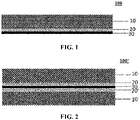
- Fig. 1 is a schematic structural diagram of one embodiment of a positive electrode sheet in a secondary battery of the present application.
- the positive electrode sheet 100 of the present application includes a positive-electrode current collector 30, a positive-electrode active material layer 10 , and a coating layer 20 arranged between the positive-electrode current collector 30 and the positive-electrode active material layer 10.
- the coating layer 20 and the positive-electrode active material layer 10 are provided only on a single side of the positive-electrode current collector 30 is shown in Fig. 1
- the present application is not limited to this.
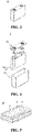
- Fig. 2 is a schematic structural diagram of another embodiment of a positive electrode sheet in the present application.
- the positive electrode sheet 100' of another embodiment of the present application may be provided with the coating layer 20, the positive-electrode active material layer 10, a coating layer 20' and a positive-electrode active material layer 10' on two sides of the positive-electrode current collector 30, respectively.
- the coating layer 20 is located between the positive-electrode current collector 30 and the positive-electrode active material layer 10
- the coating layer 20' is located between the positive-electrode current collector 30 and the positive-electrode active material layer 10'.
- the positive-electrode active material layer 10 and the positive-electrode active material layer 10' may be the same or different, and optionally both are the same, so that the manufacturing process is simple and convenient.
- the coating layer 20 and the coating layer 20' may be the same or different, and optionally both are the same, so that the manufacturing process is simple and convenient.
- the coating layers 20 and 20' include a conductive agent and a copolymer.
- the copolymer includes the following structural units (I), (II) and (III).
- R 1 and R 2 each independently represent a hydrogen atom, an unsubstituted or substituted alkyl group having 1-10 carbon atoms, an unsubstituted or substituted alkoxy group having 1-10 carbon atoms, or an unsubstituted or substituted alkenyl group having 1-10 carbon atoms, and a substituent for the substituted alkyl group having 1-10 carbon atoms, the substituted alkoxy group having 1-10 carbon atoms, and the substituted alkenyl group having 1-10 carbon atoms in R 1 and R 2 is at least one selected from hydroxyl, amino, amide, cyano, and carboxyl.
- R 3 represents a hydrogen atom, an unsubstituted or substituted alkyl group having 1-10 carbon atoms, an unsubstituted or substituted alkoxy group having 1-10 carbon atoms, an unsubstituted or substituted alkenyl group having 1-10 carbon atoms, or an aryl group having 5-20 carbon atoms, and a substituent for the substituted alkyl group having 1-10 carbon atoms, the substituted alkoxy group having 1-10 carbon atoms, and the substituted alkenyl group having 1-10 carbon atoms in R 3 is at least one selected from halogen, hydroxyl, amino, amide, cyano, and carboxyl,
- R 4 represents a hydrogen atom, an unsubstituted or substituted alkyl group having 1-10 carbon atoms, an inorganic metal ion, or -R 10 NR 11 R 12 , a substituent for the substituted alkyl group having 1-10 carbon atoms in R 4 is at least one selected from halogen, hydroxyl, amino, amide, cyano, and carboxyl, and the inorganic metal ion is a sodium ion, a potassium ion, a lithium ion, a calcium ion, or a magnesium ion,
- the resistance of the coating layer is greatly improved when the battery is overcharged, so that the safety of the battery during overcharging can be effectively improved, and the probability of overheating, fire or explosion of the battery during overcharging can be greatly reduced.
- the mechanism of action is not yet clear, but the inventor of the present application speculate as follows. That is, under normal conditions, the conductive agent is uniformly dispersed in the copolymer, so that the coating layer has good conductivity to ensure the electronic conduction between the current collector and the active material layer, so that the secondary battery can perform well in a normal environment. At this time, the resistance of the coating layer is denoted as R0.
- the temperature inside the battery increases, and the copolymer in the coating layer undergoes a violent movement of molecular chains, which causes the conductive materials dispersed in the copolymer to aggregate and destroys the conductive network of the coating layer, resulting in a significant increase in the resistance of the coating layer, and the resistance after the temperature rise is recorded as R1.
- the resistance R1 at more than 130°C after the temperature rise is more than 5 times of the resistance R0 under a normal state. Due to the rise of the resistance, the internal polarization of the battery increases rapidly, so that the voltage rises rapidly, reaching an overcharge cut-off voltage, and thus the battery cannot be charged continually, thereby improving the safety of the battery during overcharging.
- the inventor has found through in-depth research that, on the basis of the secondary battery of the present application satisfying the aforementioned design conditions, the performance of the secondary battery can be further improved if it also optionally satisfies one or more of the following parameters.
- R 1 and R 2 each independently is a hydrogen atom, or an unsubstituted or substituted alkyl group having 1-10 carbon atoms, optionally a hydrogen atom or a linear, branched or cyclic alkyl group having 1-6 carbon atoms, further optionally a hydrogen atom or a linear or branched alkyl group having 1-6 carbon atoms, and further optionally a hydrogen atom or a linear alkyl group having 1-3 carbon atoms.
- R 3 is a hydrogen atom, or an unsubstituted or substituted alkyl group having 1-10 carbon atoms, optionally a hydrogen atom or a linear, branched or cyclic alkyl group having 1-6 carbon atoms, further optionally a hydrogen atom or a linear or branched alkyl group having 1-6 carbon atoms, and further optionally a hydrogen atom or a linear alkyl group having 1-3 carbon atoms;
- R 4 is a hydrogen atom, an inorganic metal ion, or an unsubstituted or substituted alkyl group having 1-10 carbon atoms, optionally a hydrogen atom, an inorganic metal ion, or a linear, branched or cyclic alkyl group having 1-6 carbon atoms, further optionally a hydrogen atom, a sodium ion, a potassium ion or a linear or branched alkyl group having 1-6 carbon atoms
- R 5 and R 6 each independently is a hydrogen atom, or an unsubstituted or substituted alkyl groups having 1-10 carbon atoms, optionally a hydrogen atom or a linear, branched or cyclic alkyl group having 1-6 carbon atoms, further optionally a hydrogen atom or a linear or branched alkyl group having 1-6 carbon atoms, and further optionally a hydrogen atom or a linear alkyl group having 1-3 carbon atoms;
- X - is an anion selected from a halogen ion, optionally an anion selected from a chloride ion and a bromide ion, and further optionally the chloride ion.
- the average molar number of monomers of the structural unit (I) is denoted as a
- the average molar number of monomers of the structural unit (II) is denoted as b
- the average molar number of monomers of the structural unit (III) is denoted as c
- the copolymer satisfies: a/(a + b + c) ⁇ 100% is greater than 60%, and optionally 70%-85%.
- the bonding force between the coating layer and the positive-electrode current collector and the positive-electrode active material layer can be improved, so that a relatively higher cycling capacity retention rate can be maintained.
- b/(a + b + c) ⁇ 100% is below 20%, optionally 5%-15%, and optionally 5%-10%.
- c/(a + b + c) ⁇ 100% is below 20%, and optionally 10%-20%.
- the copolymer has a number average molecular weight of 10,000 to 100,000, optionally 15,000 to 50,000, and optionally 30,000 to 50,000.
- the copolymer may also include other structural units.
- the other structural units may include, but are not limited to, a structural unit derived from olefins, a structural unit derived from halogenated olefins, a structural unit derived from cycloalkanes, and the like.
- the structural units (I), (II), and (III) can be copolymerized in a random or block manner.
- the copolymer of the present application can be synthesized by a method commonly used in the art.
- it can include, but is not limited to, a method for manufacturing the copolymer of the present application by separately adding the structural unit (I), the structural unit (II), the structural unit (III) and other structural units as required into a reaction kettle, and copolymerizing them under an atmosphere of an inert gas (e.g., nitrogen) at a certain temperature; and a method for manufacturing the copolymer of the present application by respectively polymerizing the structural unit (I) and the structural unit (II) at a certain temperature, and then respectively adding a polymer obtained by polymerization of the structural unit (I) and a polymer obtained by polymerization of the structural unit (II) into a reaction kettle, then adding the structural unit (III) and other structural units as required, and copolymerizing them at a certain temperature under an atmosphere of an inert gas such as nitrogen, etc.
- an inert gas e.g., nitrogen
- the conductive agent includes at least one of conductive graphite, conductive carbon black, Ketjen black, acetylene black, carbon fiber, carbon nanotube, and graphene.
- a good conductive network can be formed to ensure good electronic conduction between the current collector and the positive-electrode active material layer.
- the coating layer further includes a binder.
- the binder may include, but is not limited to, styrene-acrylic emulsion, sodium carboxymethyl cellulose, polyvinyl alcohol, polyacrylamide, polyacrylate, and the like.
- the content of the copolymer may be more than 50 wt%, and optionally more than 65 wt%.
- the content of the copolymer in the coating layer is below 85 wt%.
- the content of the conductive agent may be 10-25 wt%.
- the coating layer can be made to have good conductivity under normal conditions to ensure the electronic conduction between the current collector and the active material layer, so that the secondary battery performs well in a normal environment.
- the thickness of the coating layer is 0.1-20 ⁇ m, optionally 0.3-10 ⁇ m, and further optionally 0.5-5 ⁇ m.
- the positive-electrode active material layers 10 and 10' include a positive-electrode active material.
- the positive-electrode active material can include, but not limited to a positive-electrode current collector and an positive-electrode film layer arranged on at least one surface of the positive-electrode current collector, wherein the positive-electrode film layer includes a positive-electrode active material, including but not limited to lithium cobaltate, lithium nickel manganese cobaltate, lithium nickel manganese aluminate, lithium iron phosphate, lithium vanadium phosphate, lithium cobalt phosphate, lithium manganese phosphate, lithium iron silicate, lithium vanadium silicate, lithium cobalt silicate, lithium manganese silicate, spinel lithium manganate, spinel lithium nickel manganate, lithium titanate, etc.
- lithium cobaltate lithium nickel manganese cobaltate
- lithium iron phosphate lithium vanadium phosphate
- the positive-electrode active material layers 10, 10' also optionally include a conductive agent.
- a conductive agent is not specifically limited, and can be selected by those skilled in the art according to actual needs.
- the conductive agent can be selected from one or more of superconducting carbon, acetylene black, carbon black, Ketjen black, carbon dots, carbon nanotubes, graphene and carbon nanofibers.
- a metal foil or a composite current collector can be employed as the positive-electrode current collector 30.
- the metal foil aluminum foil can be employed.
- the composite current collector may include a high molecular material substrate layer and a metal layer formed on at least one surface of the high molecular material substrate layer.
- the composite current collector can be formed by forming a metal material (e.g., aluminum, aluminum alloy, nickel, nickel alloy, titanium, titanium alloy, silver and silver alloy, etc.) on the high molecular material substrate (e.g., polypropylene (PP), polyethylene terephthalate (PET), polybutylene terephthalate (PBT), polystyrene (PS), polyethylene (PE), etc.).
- PP polypropylene
- PET polyethylene terephthalate
- PBT polybutylene terephthalate
- PS polystyrene
- PE polyethylene
- the positive electrode sheet of the present application can be prepared according to a commonly-used method in the art. Specifically, a coating layer can be formed on at least one surface of the current collector by gravure coating, spray coating, and the like coating methods or hot-pressing compounding and the like methods; the positive-electrode active material, the conductive agent and the binder are dispersed in a solvent (e.g., N-methyl pyrrolidone (NMP)) to prepare a positive electrode slurry, the positive electrode slurry is coated onto the coating layer, and subjected to oven-drying, cold pressing and the like procedures to obtain the positive electrode sheet.
- a solvent e.g., N-methyl pyrrolidone (NMP)
- the negative electrode sheet generally includes a negative-electrode current collector and a negative-electrode active material layer arranged on at least one surface of the negative-electrode current collector, and the negative-electrode active material layer includes a negative-electrode active material.
- a negative-electrode active material commonly used for preparing a negative electrode of a secondary battery in the art can be used as the negative-electrode active material, such as graphite, a silicon-based material, and the like.
- the aforementioned graphite may include artificial graphite, natural graphite, or a mixture thereof.
- the silicon-based material can be selected from one or more of elemental silicon, a silicon oxide compound (e.g. silicon (II) oxide), a silicon-carbon composite, a silicon-nitrogen composite and silicon alloy.
- the negative-electrode current collector has two opposite surfaces in its own thickness direction, and the negative-electrode active material layer is arranged on either or both of the opposite surfaces of the negative-electrode current collector.
- a metal foil or a composite current collector can be employed as the negative-electrode current collector.
- a metal foil a copper foil can be employed.
- the composite current collector may include a high molecular material substrate layer and a metal layer formed on at least one surface of the high molecular material substrate.
- the composite current collector can be formed by forming a metal material (e.g., copper, copper alloy, nickel, nickel alloy, titanium, titanium alloy, silver and silver alloy, etc.) on the high molecular material substrate (e.g., polypropylene (PP), polyethylene terephthalate (PET), polybutylene terephthalate (PBT), polystyrene (PS), polyethylene (PE), etc.).
- PP polypropylene
- PET polyethylene terephthalate
- PBT polybutylene terephthalate
- PS polystyrene
- PE polyethylene
- the negative-electrode active material layer usually includes a negative-electrode active material, an optional binder, an optional conductive agent and other optional adjuvants, and is usually formed by coating and drying a negative-electrode slurry.
- the negative electrode slurry is usually formed by dispersing the negative-electrode active material, the optional conductive agent, the optional binder, other optional auxiliary agents and the like in a solvent, and stirring uniformly.
- the solvent can be N-methyl pyrrolidone (NMP) or deionized water.
- the conductive agent can be selected from one or more of superconducting carbon, acetylene black, carbon black, Ketjen black, carbon dots, carbon nanotubes, graphene and carbon nanofibers.
- the binder can be selected from one or more of styrene-butadiene rubber (SBR), polyacrylic acid (PAA), sodium polyacrylate (PAAS), polyacrylamide (PAM), polyvinyl alcohol (PVA), sodium alginate (SA), polymethacrylic acid (PMAA) and carboxymethyl chitosan (CMCS).
- SBR styrene-butadiene rubber
- PAA polyacrylic acid
- PAAS sodium polyacrylate
- PAM polyacrylamide
- PVA polyvinyl alcohol
- SA sodium alginate
- PMAA polymethacrylic acid
- CMCS carboxymethyl chitosan
- a thickener such as sodium carboxymethylcellulose (CMC-Na)
- CMC-Na sodium carboxymethylcellulose
- the examples of the present application have no specific limitation on the type of the electrolyte, which can be selected according to requirements.
- the electrolyte can be solid or liquid.
- the electrolyte is liquid and typically includes an electrolyte salt and a solvent.
- the electrolyte salt can be one or more selected from lithium hexafluorophosphate (LiPF 6 ), lithium tetrafluoroborate (LiBF 4 ), lithium perchlorate (LiClO 4 ), lithium hexafluoroarsenate (LiAsF 6 ), lithium bis(fluorosulfonyl)imide (LiFSI), lithium bis(trifluoromethanesulfonyl)imide (LiTFSI), lithium trifluoromethanesulfonate (LiTFS), lithium difluoro(oxalato)borate (LiDFOB), lithium bis(oxalate)borate (LiBOB), lithium difluorophosphate (LiPO 2 F 2 ), lithium difluoro bis(oxalato)phosphate (LiDFOP) and lithium tetrafluoro(oxalato)phosphate (LiTFOP).
- LiPF 6 lithium hexafluorophosphat
- the solvent can be one or more selected from fluoroethylene carbonate (FEC), ethylene carbonate (EC), propylene carbonate (PC), ethyl methyl carbonate (EMC), diethyl carbonate (DEC), dimethyl carbonate (DMC), dipropyl carbonate (DPC), methyl propyl carbonate (MPC), ethyl propyl carbonate (EPC), butylene carbonate (BC), methyl formate (MF), methyl acetate (MA), ethyl acetate (EA), propyl acetate (PA), methyl propionate (MP), ethyl propionate (EP), propyl propionate (PP), methyl butyrate (MB), ethyl butyrate (EB), 1,4-butyrolactone (GBL), sulfolane (SF), dimethyl sulfone (MSM), methyl ethyl sulfone (EMS) and diethyl sulfone (ESE
- an additive is optionally included in the electrolyte.
- the electrolyte may include a negative-electrode film-forming additive, a positive-electrode film-forming additive, an additive for improving the overcharge performance of the battery, an additive for improving the high temperature performance of the battery, an additive for improving the low temperature performance of the battery, and the like.
- the separator can be one or more selected from a thin glass fiber film, a thin non-woven film, a thin polyethylene film, a thin polypropylene film, a thin polyvinylidene fluoride film, and a multilayer composite thin film including one or more than two of the above.
- the secondary battery may be a lithium-ion secondary battery.
- the positive electrode sheet, the negative electrode sheet and the separator can be made into an electrode assembly by a winding process or a lamination process.
- the secondary battery may include an outer package.
- the outer package can be used for encapsulating the aforementioned electrode assembly and the electrolyte.
- the outer package of the secondary battery may be a hard case, such as a hard plastic case, an aluminum case, a steel case, etc.
- the outer package of the secondary battery may also be a soft package, such as a bag-type soft package.
- the material of the soft package can be plastic, such as one or more of polypropylene (PP), polybutylene terephthalate (PBT), polybutylene succinate (PBS) and the like.
- Fig. 3 shows a secondary battery 5 with a square structure as an example.
- the outer package may include a case 51 and a cover plate 53.
- the case 51 may include a bottom plate and a side plate connected to the bottom plate, and the bottom plate and the side plate enclose to form an accommodating cavity.
- the case 51 has an opening in communication with the accommodating cavity, and the cover plate 53 can cover the opening to close the accommodating cavity.
- the positive electrode sheet, the negative electrode sheet and the separator can be subjected to a winding or lamination process to form a electrode assembly 52.
- the electrode assembly 52 is encapsulated in the accommodating cavity.
- the electrode assembly 52 is soaked in the electrolyte solution.
- the number of electrode assemblies 52 included in the secondary battery 5 may be one or more, and can be adjusted according to requirements.
- the secondary battery can be assembled into a battery module, the number of secondary batteries included in the battery module can be multiple, and the specific number can be adjusted according to the application and capacity of the battery module.
- Fig. 5 shows a battery module 4 as an example.
- multiple secondary batteries 5 may be sequentially arranged along a length direction of the battery module 4. Of course, they can also be arranged in any other way.
- the multiple secondary batteries 5 can be further fixed by fasteners.
- the battery module 4 may further include a shell having an accommodating space in which the multiple secondary batteries 5 are accommodated.
- the aforementioned battery modules can further be assembled into a battery pack, and the number of battery modules included in the battery pack can be adjusted according to the application and capacity of the battery pack.
- the battery pack 1 may include a battery box and multiple battery modules 4 disposed in the battery box.
- the battery box includes an upper box body 2 and a lower box body 3, the upper box body 2 can cover the lower box body 3 to form a closed space for accommodating the battery modules 4.
- the multiple battery modules 4 can be arranged in the battery box in any way.
- the secondary battery can be used as a power source of the device, and can also be used as an energy storage unit of the device.
- the device can be, but not limited to, mobile devices (e.g., a mobile phone, a laptop, etc.), electric vehicles (e.g., a all-electric vehicle, a hybrid electric vehicle, a plug-in hybrid electric vehicle, an electric bicycle, an electric scooter, an electric golf cart, an electric truck, etc.), electric trains, ships and satellites, energy storage systems, etc.
- the secondary battery, battery module or battery pack can be selected according to the use requirements of the device.
- Fig. 8 shows a device as an example.
- the device is a all-electric vehicle, a hybrid electric vehicle or a plug-in hybrid electric vehicle, and the like.
- the battery pack or battery module can be employed.
- the device may be a mobile phone, a tablet, a laptop, etc. Lighting and thinning of the device is generally required, and thus the secondary battery can be employed as the power source.
- Raw materials 1-1, 2-1 and 3-1 are dissolved in water at a mass ratio of 80:5:15, and stirred for dissolving them.
- high-pressure nitrogen is introduced for 10 min, and ammonia water is introduced while the addition of nitrogen, and heated up to 60°C, and added with iron powder, a AlCl 3 aqueous solution with a concentration of 20% and K 2 S 2 O 8 as an initiator, adjusted with sulfuric acid and a sodium hydroxide solution until the pH of the reaction system is about 7, and reacted at a constant reaction temperature of 65°C for 4 hours.
- the heating was stopped, and the mixture was stirred and sufficiently cooled, and then dried and aged for 8 hours to obtain the copolymer 1.
- the copolymer 1 includes a structural unit (I-1), a structural unit (II-1) and a structural unit (III-1). Also, the copolymer 1 satisfies: a/(a + b + c) ⁇ 100% is 80%, b/(a + b + c) ⁇ 100% is 5%, c/(a + b + c) ⁇ 100% is 15%, and the number average molecular weight is 30,000.
- copolymers 2-16 are similar to that of the copolymer 1, except that the types and adding amount of respective raw materials, etc., are adjusted. See Table 2 below for details.
- the molecular weight and the ratio of each structural unit can be determined by the following method.
- the prepared copolymer is dissolved in water, and determined with a gel permeation chromatograph (GPC) (model: Agilent GPC 50, manufacturer: Agilent) for the number average molecular weight of the prepared copolymer.
- GPC gel permeation chromatograph
- the prepared copolymer is dissolved in deuterated water to obtain a sample to be tested, the sample is placed in a nuclear magnetic tube, and determined with a 400 MHz nuclear magnetic resonance instrument (model: Bruker Avance III 400 MHz NMR, manufacturer: Bruker) for its H spectrum, so as to observe the peak ratio of different monomers of it to determine the ratio of different monomers.
- a 400 MHz nuclear magnetic resonance instrument model: Bruker Avance III 400 MHz NMR, manufacturer: Bruker
- the copolymer 1 prepared above, conductive carbon black as a conductive agent (Super-P) and styrene-acrylic emulsion as a binder were added into deionized water as a solvent in a mass ratio of 70:15:15, and fully stirred to prepare a slurry.
- the obtained slurry was coated on surfaces at both sides of a aluminum foil as a current collector, and then dried to form a coating layer with a thickness of 2 ⁇ m.
- NCM811 LiNi 0.8 Co 0.1 Mn 0.1 O 2
- acetylene black as a conductive agent
- PVDF polyvinylidene fluoride
- Ethylene carbonate (EC) and diethyl carbonate (DEC) were mixed in a mass ratio of 50:50 to obtain the electrolyte solution.
- the positive electrode sheet, the separator and the negative electrode sheet were stacked in sequence, so that the separator is located between the positive electrode sheet and the negative electrode sheet to play a role of isolation, and then they were wound to obtain a electrode assembly.
- the electrode assembly was placed in an outer package, injected with the formulated electrolyte solution, and encapsulated to obtain the secondary battery.
- Example 2 The preparation methods of them were similar to that of Example 1, except that a different copolymer was selected in the coating layer. See Table 3 below for details.
- the preparation method of it was similar to that of Example 1, except that the coating layer was arranged on neither surface of the positive-electrode current collector.
- Example 2 The preparation methods of them were similar to that of Example 1, except that a different copolymer was selected in the coating layer. See Table 3 below for details.
- the prepared secondary battery was subjected to thermal insulation with thermal insulation cotton placed at both ends of the outside of the battery, and charged at a charging rate of 1C. During the charging process, the temperature at the surface of the battery and the battery voltage were monitored.
- the secondary batteries prepared in the examples and comparative examples were charged at a constant current rate of 0.5C to a charging cut-off voltage of 4.25 V, then charged at a constant voltage to a current of ⁇ 0.05C and allowed to stand for 30 min, and then discharged at a constant current rate of 1C to a discharging cut-off voltage of 2.8 V and allowed to stand for 30 min, and the battery capacity C0 at this time was recorded.
- the battery was charged and discharged for 1500 cycles, and the battery capacity after 1500 cycles was recorded as C1.
- the cycling capacity retention rate at 25°C of the secondary battery was calculated by the following formula.
- the time required to reach the overcharging cut-off voltage could be further shortened without significantly affecting the cycling capacity retention rate, that was, the safety of the battery during overcharging could be further improved.
Landscapes
- Chemical & Material Sciences (AREA)
- Chemical Kinetics & Catalysis (AREA)
- Electrochemistry (AREA)
- General Chemical & Material Sciences (AREA)
- Engineering & Computer Science (AREA)
- Manufacturing & Machinery (AREA)
- Composite Materials (AREA)
- Materials Engineering (AREA)
- Health & Medical Sciences (AREA)
- Organic Chemistry (AREA)
- Polymers & Plastics (AREA)
- Medicinal Chemistry (AREA)
- Secondary Cells (AREA)
- Battery Electrode And Active Subsutance (AREA)
- Connection Of Batteries Or Terminals (AREA)
Abstract
Description
- The present application relates to a secondary battery, and in particular to a secondary battery having a coating layer between a positive-electrode current collector and a positive-electrode active material layer, and a battery module, battery pack, and device having the secondary battery.
- In the use of a secondary battery, there are repeated charging and discharging processes. During the charging process, the charging upper limit voltage of the secondary battery needs to be controlled by a limiting mechanism. However, when the limiting mechanism fails, the voltage exceeds the safe voltage of the secondary battery, and thus, there will be problems such as lithium precipitating on a negative electrode, oxygen release on a positive electrode, and heat release from the battery, which will seriously lead to thermal runaway inside the battery, resulting in serious safety accidents such as fire and explosion. Therefore, in order to enable the secondary battery to be applied massively, safely and widely, it is urgent to improve the overcharge safety of the secondary battery.
- The present application is developed in view of the aforementioned technical problems, and an objective of it is to enable a secondary battery to take better overcharge safety and cycling performance into account at the same time.
- In order to achieve the aforementioned objective, the present application provides a secondary battery including a positive electrode sheet which includes: a positive-electrode current collector, a positive-electrode active material layer, and a coating layer arranged between the positive-electrode current collector and the positive-electrode active material layer, wherein
- the coating layer includes a conductive agent and a copolymer,
- the copolymer includes the following structural unit (I), structural unit (II) and structural unit (III),

- in the structural unit (I), R1 and R2 each independently represent a hydrogen atom, an unsubstituted or substituted alkyl group having 1-10 carbon atoms, an unsubstituted or substituted alkoxy group having 1-10 carbon atoms, or an unsubstituted or substituted alkenyl group having 1-10 carbon atoms, and
- a substituent for the substituted alkyl group having 1-10 carbon atoms, the substituted alkoxy group having 1-10 carbon atoms, and the substituted alkenyl group having 1-10 carbon atoms in R1 and R2 is at least one selected from hydroxyl, amino, amide, cyano, and carboxyl,

- in the structural unit (II), R3 represents a hydrogen atom, an unsubstituted or substituted alkyl group having 1-10 carbon atoms, an unsubstituted or substituted alkoxy group having 1-10 carbon atoms, an unsubstituted or substituted alkenyl group having 1-10 carbon atoms, or an aryl group having 5-20 carbon atoms, and a substituent for the substituted alkyl group having 1-10 carbon atoms, the substituted alkoxy group having 1-10 carbon atoms, and the substituted alkenyl group having 1-10 carbon atoms in R3 is at least one selected from halogen, hydroxyl, amino, amide, cyano, and carboxyl,
- R4 represents a hydrogen atom, an unsubstituted or substituted alkyl group having 1-10 carbon atoms, an inorganic metal ion, or -R10NR11R12, a substituent for the substituted alkyl group having 1-10 carbon atoms in R4 is at least one selected from halogen, hydroxyl, amino, amide, cyano, and carboxyl, and the inorganic metal ion is a sodium ion, a potassium ion, a lithium ion, a calcium ion, or a magnesium ion,
- wherein, R10 represents an unsubstituted or substituted alkylene group having 1-10 carbon atoms or an unsubstituted or substituted alkenylene group having 2-10 carbon atoms, and a substituent for the substituted alkylene group having 1-10 carbon atoms or the substituted alkenylene group having 2-10 carbon atoms in R10 is at least one selected from halogen, hydroxyl, amino, amide, cyano, and carboxyl,
- R11 and R12 each independently represent an unsubstituted or substituted alkyl group having 1-10 carbon atoms, an unsubstituted or substituted alkenyl group having 1-10 carbon atoms or an aryl group having 5-20 carbon atoms, and a substituent for the substituted alkyl group having 1-10 carbon atoms and the substituted alkenyl group having 1-10 carbon atoms in R11 and R12 is at least one selected from halogen, hydroxyl, amino, amide, cyano and carboxyl,

- in the structural unit (III), R5 and R6 each independently represent a hydrogen atom, an unsubstituted or substituted alkyl group having 1-10 carbon atoms, X- represents an anion selected from a halogen ion, a sulfate ion and a sulfonate ion, and a substituent for the substituted alkyl group having 1-10 carbon atoms in R5 and R6 is at least one selected from halogen, hydroxyl, amino, amide, cyano, and carboxyl.
- By disposing the coating including the aforementioned specific copolymer between the positive-electrode current collector and the positive-electrode active material layer, the safety of the battery during overcharging can be effectively improved, and the probability of overheating, fire or explosion of the battery during overcharging can be greatly reduced.
- In any embodiment, in the coating layer, the content of the copolymer may be more than 50 wt%, and optionally 65 wt%-85 wt%. By setting the content of the copolymer in the coating layer to the aforementioned range, the electronic conduction between the current collector and the active material layer can be ensured under normal conditions, and a relatively higher cycling capacity retention rate can be maintained. Furthermore, the conductive network of the coating layer is easily destroyed when the battery is overcharged, so that the safety of the battery is improved when the battery is overcharged, and in turn it can be avoided that the resistance of the coating layer is not greatly increased since the conductive network of the coating layer cannot be destroyed when the battery is overcharged.
- In any embodiment, the thickness of the coating layer is 0.1-20 µm, optionally 0.3-10 µm, and further optionally 0.5-5 µm. By setting the thickness of the coating layer within the aforementioned range, miniaturization, high cycling capacity retention rate and excellent overcharge safety of the secondary battery can be taken into account at the same time, and in turn, on one hand, the influence on the conductive performance can be avoided, and the battery electrode sheet can be prevented from being thicker, thereby facilitating the miniaturization of the battery; and on the other hand, it can be avoided that after the temperature rise caused by the overcharge of the battery, the resistance of the coating layer increases in a small proportion and thus cannot play the role of increasing the resistance and polarization.
- In any embodiment, the conductive agent used in the coating layer includes at least one of conductive graphite, conductive carbon black, Ketjen black, acetylene black, carbon fiber, carbon nanotube, and graphene. By using such a conductive agent in the coating layer, a good conductive network can be formed to ensure good electronic conduction between the current collector and the positive-electrode active material layer.
- In any embodiment, the coating layer may further include a binder. Therefore, the coating layer can be made relatively stable, and the application range of the secondary battery is improved.
- In any embodiment, the average molar number of monomers of the structural unit (I) is denoted as a, the average molar number of monomers of the structural unit (II) is denoted as b, and the average molar number of monomers of the structural unit (III) is denoted as c, then the copolymer satisfies: 60% ≤ a/(a + b + c) × 100%, and optionally 70% ≤ a/(a + b + c) × 100% ≤ 85%. By setting a/(a + b + c) × 100% to a specific range, the bonding force between the coating layer and the positive-electrode current collector and the positive-electrode active material layer can be improved, so that a relatively higher cycling capacity retention rate can be maintained.
- In any embodiment, the average molar number of monomers of the structural unit (I) is denoted as a, the average molar number of monomers of the structural unit (II) is denoted as b, and the average molar number of monomers of the structural unit (III) is denoted as c, then the copolymer satisfies: b/(a + b + c) × 100% ≤ 20%, optionally 5% ≤ b/(a + b + c) × 100% ≤ 15%, and optionally 5% ≤ b/(a + b + c) × 100% ≤ 10%. By setting b/(a + b + c) × 100% to a specific range, the bonding force between the coating layer and the positive-electrode current collector and the positive-electrode active material layer can be improved, so that a relatively higher cycling capacity retention rate can be maintained.
- In any embodiment, the average molar number of monomers of the structural unit (I) is denoted as a, the average molar number of monomers of the structural unit (II) is denoted as b, and the average molar number of monomers of the structural unit (III) is denoted as c, then the copolymer satisfies: c/(a + b + c) × 100% ≤ 20%, and optionally 10% ≤ c/(a + b + c) × 100% ≤ 20%. By setting c/(a + b + c) × 100% to the aforementioned specific range, when the battery is overcharged, the resistance of the coating layer is greatly improved, playing the role of inhibiting the overcharge of the battery.
- In any embodiment, in the aforementioned structural unit (I), R1 and R2 each independently is a hydrogen atom, or an unsubstituted or substituted alkyl group having 1-10 carbon atoms, optionally a hydrogen atom or a linear, branched or cyclic alkyl group having 1-6 carbon atoms, optionally a hydrogen atom or a linear or branched alkyl group having 1-6 carbon atoms, and further optionally a hydrogen atom or a linear alkyl group having 1-3 carbon atoms. Therefore, it enables the manufacturing process to be simple and convenient and reduces the production cost.
- In any embodiment, in the structural unit (II), R3 is a hydrogen atom, or an unsubstituted or substituted alkyl group having 1-10 carbon atoms, optionally a hydrogen atom or a linear, branched or cyclic alkyl group having 1-6 carbon atoms, further optionally a hydrogen atom or a linear or branched alkyl group having 1-6 carbon atoms, and further optionally a hydrogen atom or a linear alkyl group having 1-3 carbon atoms; R4 is a hydrogen atom, an inorganic metal ion, or an unsubstituted or substituted alkyl group having 1-10 carbon atoms, optionally a hydrogen atom, an inorganic metal ion, or a linear, branched or cyclic alkyl group having 1-6 carbon atoms, further optionally a hydrogen atom, a sodium ion, a potassium ion or a linear or branched alkyl group having 1-6 carbon atoms, and further optionally a hydrogen atom, a sodium ion, a potassium ion or a linear alkyl group having 1-3 carbon atoms. Therefore, it enables the manufacturing process to be simple and convenient and reduces the production cost.
- In any embodiment, in the structural unit (III), R5 and R6 each independently is a hydrogen atom, or an unsubstituted or substituted alkyl groups having 1-10 carbon atoms, optionally a hydrogen atom or a linear, branched or cyclic alkyl group having 1-6 carbon atoms, further optionally a hydrogen atom or a linear or branched alkyl group having 1-6 carbon atoms, and further optionally a hydrogen atom or a linear alkyl group having 1-3 carbon atoms; X- is an anion selected from a halogen ion, optionally an anion selected from a chloride ion and a bromide ion, and further optionally the chloride ion. Therefore, it enables the manufacturing process to be simple and convenient and reduces the production cost.
- In any embodiment, the structural units (I), (II), and (III) are copolymerized in a random or block manner.
- In any embodiment, the copolymer has a number average molecular weight of 10,000 to 100,000, and optionally 15,000 to 50,000.
- A second aspect of the present application provides a battery module including the secondary battery according to the first aspect of the present application.
- A third aspect of the present application provides a battery pack including the battery module according to the second aspect of the present application.
- A fourth aspect of the present application provides an device including at least one of the secondary battery according to the first aspect of the present application, the battery module according to the second aspect of the present application, or the battery pack according to the third aspect of the present application.
- The battery module, battery pack and device of the present application include the secondary battery provided by the present application, and thus have at least the same advantages as the secondary battery.
-
-
Fig. 1 is a schematic structural diagram of one embodiment of a positive electrode sheet in a secondary battery of the present application. -
Fig. 2 is a schematic structural diagram of another embodiment of a positive electrode sheet in a secondary battery of the present application. -
Fig. 3 is a schematic diagram of a secondary battery according to one embodiment of the present application. -
Fig. 4 is an exploded view of the secondary battery according to one embodiment of the present application shown inFig. 3 . -
Fig. 5 is a schematic diagram of a battery module according to one embodiment of the present application. -
Fig. 6 is a schematic diagram of a battery pack according to one embodiment of the present application. -
Fig. 7 is an exploded view of the battery pack according to one embodiment of the present application shown inFig. 6 . -
Fig. 8 is a schematic diagram of a device in which a secondary battery is used as a power source, according to one embodiment of the present application. - In order to make the objectives, technical solutions and advantages of the present application clearer, the embodiments of the present application will be described in detail below with reference to the accompanying drawings. However, it should be understood by those of ordinary skills in the art that these embodiments are only used for illustrating the technical solutions of the present application, rather than limiting them.
- For the sake of conciseness, the present application specifically discloses some numerical ranges. However, any lower limit can be combined with any upper limit to form an unspecified range; and any lower limit can be combined with other lower limits to form an unspecified range, and likewise, any upper limit can be combined with any other upper limit to form an unspecified range. Furthermore, every point or single numerical value between the endpoints of a range is included within the range, even if not expressly recited. Moreover, each separately disclosed point or single numerical value itself can be used as a lower or upper limit to form an unspecified range in combination with any other point or single numerical value or with other lower or upper limits.
- In the description herein, it should be noted that, "above" and "below" are inclusive of the numerical numeral itself, and the meaning of "more" in "one or more" is two and more, unless otherwise specified.
- The aforementioned summary of the present application is not intended to describe each disclosed embodiment or every implementation of the present application. The following description illustrates exemplary embodiments more specifically. In various places throughout the present application, guidance is provided through a series of examples, which examples can be used in various combinations. In various examples, the enumeration is merely a representative group, and should not be construed as exhaustive.
- A secondary battery refers to a battery that can be used continually by activating a active material in a charging manner, after the battery is discharged. Generally, the secondary battery pack includes a positive electrode sheet, a negative electrode sheet, a separator and an electrolyte. During the charging and discharging process of the battery, active ions are intercalated and deintercalated back and forth between the positive electrode sheet and the negative electrode sheet. The separator is arranged between the positive electrode sheet and the negative electrode sheet, which can insulate electrons, prevent internal short circuit, and meanwhile allow active ions to pass through and move between the positive and negative electrodes, playing the role of isolating. The electrolyte plays the role of conducting ions between the positive electrode sheet and the negative electrode sheet.
-
Fig. 1 is a schematic structural diagram of one embodiment of a positive electrode sheet in a secondary battery of the present application. As shown inFig. 1 , thepositive electrode sheet 100 of the present application includes a positive-electrodecurrent collector 30, a positive-electrodeactive material layer 10 , and acoating layer 20 arranged between the positive-electrodecurrent collector 30 and the positive-electrodeactive material layer 10. Moreover, although the embodiment in which thecoating layer 20 and the positive-electrodeactive material layer 10 are provided only on a single side of the positive-electrodecurrent collector 30 is shown inFig. 1 , the present application is not limited to this.Fig. 2 is a schematic structural diagram of another embodiment of a positive electrode sheet in the present application. As shown inFig. 2 , the positive electrode sheet 100' of another embodiment of the present application may be provided with thecoating layer 20, the positive-electrodeactive material layer 10, a coating layer 20' and a positive-electrode active material layer 10' on two sides of the positive-electrodecurrent collector 30, respectively. Thecoating layer 20 is located between the positive-electrodecurrent collector 30 and the positive-electrodeactive material layer 10, and the coating layer 20' is located between the positive-electrodecurrent collector 30 and the positive-electrode active material layer 10'. The positive-electrodeactive material layer 10 and the positive-electrode active material layer 10' may be the same or different, and optionally both are the same, so that the manufacturing process is simple and convenient. Thecoating layer 20 and the coating layer 20' may be the same or different, and optionally both are the same, so that the manufacturing process is simple and convenient. - The coating layers 20 and 20' include a conductive agent and a copolymer. The copolymer includes the following structural units (I), (II) and (III).

a substituent for the substituted alkyl group having 1-10 carbon atoms, the substituted alkoxy group having 1-10 carbon atoms, and the substituted alkenyl group having 1-10 carbon atoms in R1 and R2 is at least one selected from hydroxyl, amino, amide, cyano, and carboxyl. )
- R4 represents a hydrogen atom, an unsubstituted or substituted alkyl group having 1-10 carbon atoms, an inorganic metal ion, or -R10NR11R12, a substituent for the substituted alkyl group having 1-10 carbon atoms in R4 is at least one selected from halogen, hydroxyl, amino, amide, cyano, and carboxyl, and the inorganic metal ion is a sodium ion, a potassium ion, a lithium ion, a calcium ion, or a magnesium ion,
- wherein, R10 represents an unsubstituted or substituted alkylene group having 1-10 carbon atoms or an unsubstituted or substituted alkenylene group having 2-10 carbon atoms, and a substituent for the substituted alkylene group having 1-10 carbon atoms or the substituted alkenylene group having 2-10 carbon atoms in R10 is at least one selected from halogen, hydroxyl, amino, amide, cyano, and carboxyl,
- R11 and R12 each independently represent an unsubstituted or substituted alkyl group having 1-10 carbon atoms, an unsubstituted or substituted alkenyl group having 1-10 carbon atoms or an aryl group having 5-20 carbon atoms, and a substituent for the substituted alkyl group having 1-10 carbon atoms and the substituted alkenyl group having 1-10 carbon atoms in R11 and R12 is at least one selected from halogen, hydroxyl, amino, amide, cyano and carboxyl. )

- (in the structural unit (III), R5 and R6 each independently represent a hydrogen atom, an unsubstituted or substituted alkyl group having 1-10 carbon atoms, X- represents an anion selected from a halogen ion, a sulfate ion and a sulfonate ion, and a substituent for the substituted alkyl group having 1-10 carbon atoms in R5 and R6 is at least one selected from halogen, hydroxyl, amino, amide, cyano, and carboxyl. )
- By disposing the coating including the aforementioned specific copolymer between the positive-electrode current collector and the positive-electrode active material layer, the resistance of the coating layer is greatly improved when the battery is overcharged, so that the safety of the battery during overcharging can be effectively improved, and the probability of overheating, fire or explosion of the battery during overcharging can be greatly reduced.
- The mechanism of action is not yet clear, but the inventor of the present application speculate as follows. That is, under normal conditions, the conductive agent is uniformly dispersed in the copolymer, so that the coating layer has good conductivity to ensure the electronic conduction between the current collector and the active material layer, so that the secondary battery can perform well in a normal environment. At this time, the resistance of the coating layer is denoted as R0. On the other hand, when the battery is overcharged, the temperature inside the battery increases, and the copolymer in the coating layer undergoes a violent movement of molecular chains, which causes the conductive materials dispersed in the copolymer to aggregate and destroys the conductive network of the coating layer, resulting in a significant increase in the resistance of the coating layer, and the resistance after the temperature rise is recorded as R1. The resistance R1 at more than 130°C after the temperature rise is more than 5 times of the resistance R0 under a normal state. Due to the rise of the resistance, the internal polarization of the battery increases rapidly, so that the voltage rises rapidly, reaching an overcharge cut-off voltage, and thus the battery cannot be charged continually, thereby improving the safety of the battery during overcharging.
- The inventor has found through in-depth research that, on the basis of the secondary battery of the present application satisfying the aforementioned design conditions, the performance of the secondary battery can be further improved if it also optionally satisfies one or more of the following parameters.
- In some embodiments, in the aforementioned structural unit (I), R1 and R2 each independently is a hydrogen atom, or an unsubstituted or substituted alkyl group having 1-10 carbon atoms, optionally a hydrogen atom or a linear, branched or cyclic alkyl group having 1-6 carbon atoms, further optionally a hydrogen atom or a linear or branched alkyl group having 1-6 carbon atoms, and further optionally a hydrogen atom or a linear alkyl group having 1-3 carbon atoms.
- In some embodiments, in the aforementioned structural unit (II), R3 is a hydrogen atom, or an unsubstituted or substituted alkyl group having 1-10 carbon atoms, optionally a hydrogen atom or a linear, branched or cyclic alkyl group having 1-6 carbon atoms, further optionally a hydrogen atom or a linear or branched alkyl group having 1-6 carbon atoms, and further optionally a hydrogen atom or a linear alkyl group having 1-3 carbon atoms; R4 is a hydrogen atom, an inorganic metal ion, or an unsubstituted or substituted alkyl group having 1-10 carbon atoms, optionally a hydrogen atom, an inorganic metal ion, or a linear, branched or cyclic alkyl group having 1-6 carbon atoms, further optionally a hydrogen atom, a sodium ion, a potassium ion or a linear or branched alkyl group having 1-6 carbon atoms, and further optionally a hydrogen atom, a sodium ion, a potassium ion or a linear alkyl group having 1-3 carbon atoms.
- In some embodiments, in the aforementioned structural unit (III), R5 and R6 each independently is a hydrogen atom, or an unsubstituted or substituted alkyl groups having 1-10 carbon atoms, optionally a hydrogen atom or a linear, branched or cyclic alkyl group having 1-6 carbon atoms, further optionally a hydrogen atom or a linear or branched alkyl group having 1-6 carbon atoms, and further optionally a hydrogen atom or a linear alkyl group having 1-3 carbon atoms; X- is an anion selected from a halogen ion, optionally an anion selected from a chloride ion and a bromide ion, and further optionally the chloride ion.
- In some embodiments, in the copolymer, the average molar number of monomers of the structural unit (I) is denoted as a, the average molar number of monomers of the structural unit (II) is denoted as b, and the average molar number of monomers of the structural unit (III) is denoted as c, then the copolymer satisfies: a/(a + b + c) × 100% is greater than 60%, and optionally 70%-85%. By controlling a/(a + b + c) × 100% to a specific range, the bonding force between the coating layer and the positive-electrode current collector and the positive-electrode active material layer can be improved, so that a relatively higher cycling capacity retention rate can be maintained.
- In some embodiments, in the copolymer, b/(a + b + c) × 100% is below 20%, optionally 5%-15%, and optionally 5%-10%. By controlling b/(a + b + c) to a specific range, the bonding force between the coating layer and the positive-electrode current collector and the positive-electrode active material layer can be improved, so that a relatively higher cycling capacity retention rate can be maintained.
- In some embodiments, in the copolymer, c/(a + b + c) × 100% is below 20%, and optionally 10%-20%. By controlling c/(a + b + c) within a specific range, the resistance of the coating layer can be further increased when the battery is overcharged, thereby further improving the overcharge safety of the battery.
- In some embodiments, the copolymer has a number average molecular weight of 10,000 to 100,000, optionally 15,000 to 50,000, and optionally 30,000 to 50,000. By making the number average molecular weight of the copolymer within the aforementioned range, high mechanical strength, high thermal stability, and excellent overcharge safety can be taken into account at the same time, and it can be avoided that the movement of the molecular chain of the copolymer becomes difficult, which otherwise causes that it is difficult to destroy the conductive network of the coating layer during overcharge of the battery and thus the overcharge safety of the battery cannot be improved. On the other hand, it is possible to avoid that the mechanical strength of the coating layer is reduced and thus the battery is easily broken when it is subjected to an external force, and in turn, it is possible to avoid that the thermal stability of the copolymer is reduced and thus the copolymer is melted or degraded during the temperature rise due to overcharge of the battery, etc.
- In some embodiments, the copolymer may also include other structural units. The other structural units may include, but are not limited to, a structural unit derived from olefins, a structural unit derived from halogenated olefins, a structural unit derived from cycloalkanes, and the like.
- In some embodiments, the structural units (I), (II), and (III) can be copolymerized in a random or block manner.
- The copolymer of the present application can be synthesized by a method commonly used in the art. For example, it can include, but is not limited to, a method for manufacturing the copolymer of the present application by separately adding the structural unit (I), the structural unit (II), the structural unit (III) and other structural units as required into a reaction kettle, and copolymerizing them under an atmosphere of an inert gas (e.g., nitrogen) at a certain temperature; and a method for manufacturing the copolymer of the present application by respectively polymerizing the structural unit (I) and the structural unit (II) at a certain temperature, and then respectively adding a polymer obtained by polymerization of the structural unit (I) and a polymer obtained by polymerization of the structural unit (II) into a reaction kettle, then adding the structural unit (III) and other structural units as required, and copolymerizing them at a certain temperature under an atmosphere of an inert gas such as nitrogen, etc.
- In some embodiments, the conductive agent includes at least one of conductive graphite, conductive carbon black, Ketjen black, acetylene black, carbon fiber, carbon nanotube, and graphene. By including such a conductive agent in the coating layer, a good conductive network can be formed to ensure good electronic conduction between the current collector and the positive-electrode active material layer.
- In some embodiments, the coating layer further includes a binder. The binder may include, but is not limited to, styrene-acrylic emulsion, sodium carboxymethyl cellulose, polyvinyl alcohol, polyacrylamide, polyacrylate, and the like.
- In some embodiments, in the coating layer, the content of the copolymer may be more than 50 wt%, and optionally more than 65 wt%. By setting the content of the copolymer in the coating layer to the aforementioned range, the electronic conduction between the current collector and the active material layer can be ensured under normal conditions, and a relatively higher cycling capacity retention rate can be maintained. Furthermore, the conductive network of the coating layer is easily destroyed when the battery is overcharged, so that the safety of the battery is improved when the battery is overcharged, and in turn it can be avoided that the resistance of the coating layer is not greatly increased since the conductive network of the coating layer cannot be destroyed when the battery is overcharged. Optionally, the content of the copolymer is below 85 wt%.
- In some embodiments, in the coating layer, the content of the conductive agent may be 10-25 wt%. By setting the content of the conductive agent to the aforementioned range, the coating layer can be made to have good conductivity under normal conditions to ensure the electronic conduction between the current collector and the active material layer, so that the secondary battery performs well in a normal environment.
- In some embodiments, the thickness of the coating layer is 0.1-20 µm, optionally 0.3-10 µm, and further optionally 0.5-5 µm. By setting the thickness of the coating layer within the aforementioned range, miniaturization, high cycling capacity retention rate and excellent overcharge safety of the secondary battery can be taken into account at the same time, and in turn, on one hand, the influence on the conductive performance can be avoided, and the battery electrode sheet can be prevented from being thicker, which otherwise goes against the miniaturization of the battery; and on the other hand, it can be avoided that after the temperature rise caused by the overcharge of the battery, the resistance of the coating layer increases in a small proportion and thus cannot play the role of increasing the resistance and polarization.
- In the secondary battery of the present application, the positive-electrode active material layers 10 and 10' include a positive-electrode active material. The positive-electrode active material can include, but not limited to a positive-electrode current collector and an positive-electrode film layer arranged on at least one surface of the positive-electrode current collector, wherein the positive-electrode film layer includes a positive-electrode active material, including but not limited to lithium cobaltate, lithium nickel manganese cobaltate, lithium nickel manganese aluminate, lithium iron phosphate, lithium vanadium phosphate, lithium cobalt phosphate, lithium manganese phosphate, lithium iron silicate, lithium vanadium silicate, lithium cobalt silicate, lithium manganese silicate, spinel lithium manganate, spinel lithium nickel manganate, lithium titanate, etc. One or more of these can be used as the positive-electrode active material.
- The positive-electrode active material layers 10, 10' also optionally include a conductive agent. However, the type of the conductive agent is not specifically limited, and can be selected by those skilled in the art according to actual needs. As an example, the conductive agent can be selected from one or more of superconducting carbon, acetylene black, carbon black, Ketjen black, carbon dots, carbon nanotubes, graphene and carbon nanofibers.
- In the secondary battery of the present application, a metal foil or a composite current collector can be employed as the positive-electrode
current collector 30. For example, as the metal foil, aluminum foil can be employed. The composite current collector may include a high molecular material substrate layer and a metal layer formed on at least one surface of the high molecular material substrate layer. The composite current collector can be formed by forming a metal material (e.g., aluminum, aluminum alloy, nickel, nickel alloy, titanium, titanium alloy, silver and silver alloy, etc.) on the high molecular material substrate (e.g., polypropylene (PP), polyethylene terephthalate (PET), polybutylene terephthalate (PBT), polystyrene (PS), polyethylene (PE), etc.). - The positive electrode sheet of the present application can be prepared according to a commonly-used method in the art. Specifically, a coating layer can be formed on at least one surface of the current collector by gravure coating, spray coating, and the like coating methods or hot-pressing compounding and the like methods; the positive-electrode active material, the conductive agent and the binder are dispersed in a solvent (e.g., N-methyl pyrrolidone (NMP)) to prepare a positive electrode slurry, the positive electrode slurry is coated onto the coating layer, and subjected to oven-drying, cold pressing and the like procedures to obtain the positive electrode sheet.
- In a secondary battery, the negative electrode sheet generally includes a negative-electrode current collector and a negative-electrode active material layer arranged on at least one surface of the negative-electrode current collector, and the negative-electrode active material layer includes a negative-electrode active material.
- In the secondary battery of the present application, a negative-electrode active material commonly used for preparing a negative electrode of a secondary battery in the art can be used as the negative-electrode active material, such as graphite, a silicon-based material, and the like. The aforementioned graphite may include artificial graphite, natural graphite, or a mixture thereof. The silicon-based material can be selected from one or more of elemental silicon, a silicon oxide compound (e.g. silicon (II) oxide), a silicon-carbon composite, a silicon-nitrogen composite and silicon alloy.
- As an example, the negative-electrode current collector has two opposite surfaces in its own thickness direction, and the negative-electrode active material layer is arranged on either or both of the opposite surfaces of the negative-electrode current collector.
- In the secondary battery of the present application, a metal foil or a composite current collector can be employed as the negative-electrode current collector. For example, as the metal foil, a copper foil can be employed. The composite current collector may include a high molecular material substrate layer and a metal layer formed on at least one surface of the high molecular material substrate. The composite current collector can be formed by forming a metal material (e.g., copper, copper alloy, nickel, nickel alloy, titanium, titanium alloy, silver and silver alloy, etc.) on the high molecular material substrate (e.g., polypropylene (PP), polyethylene terephthalate (PET), polybutylene terephthalate (PBT), polystyrene (PS), polyethylene (PE), etc.).
- In the secondary battery of the present application, the negative-electrode active material layer usually includes a negative-electrode active material, an optional binder, an optional conductive agent and other optional adjuvants, and is usually formed by coating and drying a negative-electrode slurry. The negative electrode slurry is usually formed by dispersing the negative-electrode active material, the optional conductive agent, the optional binder, other optional auxiliary agents and the like in a solvent, and stirring uniformly. The solvent can be N-methyl pyrrolidone (NMP) or deionized water.
- As an example, the conductive agent can be selected from one or more of superconducting carbon, acetylene black, carbon black, Ketjen black, carbon dots, carbon nanotubes, graphene and carbon nanofibers.
- As an example, the binder can be selected from one or more of styrene-butadiene rubber (SBR), polyacrylic acid (PAA), sodium polyacrylate (PAAS), polyacrylamide (PAM), polyvinyl alcohol (PVA), sodium alginate (SA), polymethacrylic acid (PMAA) and carboxymethyl chitosan (CMCS).
- Other optional adjuvants are for example a thickener (such as sodium carboxymethylcellulose (CMC-Na)), etc.
- The examples of the present application have no specific limitation on the type of the electrolyte, which can be selected according to requirements. For example, the electrolyte can be solid or liquid.
- In some embodiments, the electrolyte is liquid and typically includes an electrolyte salt and a solvent.
- As an example, the electrolyte salt can be one or more selected from lithium hexafluorophosphate (LiPF6), lithium tetrafluoroborate (LiBF4), lithium perchlorate (LiClO4), lithium hexafluoroarsenate (LiAsF6), lithium bis(fluorosulfonyl)imide (LiFSI), lithium bis(trifluoromethanesulfonyl)imide (LiTFSI), lithium trifluoromethanesulfonate (LiTFS), lithium difluoro(oxalato)borate (LiDFOB), lithium bis(oxalate)borate (LiBOB), lithium difluorophosphate (LiPO2F2), lithium difluoro bis(oxalato)phosphate (LiDFOP) and lithium tetrafluoro(oxalato)phosphate (LiTFOP).
- As an example, the solvent can be one or more selected from fluoroethylene carbonate (FEC), ethylene carbonate (EC), propylene carbonate (PC), ethyl methyl carbonate (EMC), diethyl carbonate (DEC), dimethyl carbonate (DMC), dipropyl carbonate (DPC), methyl propyl carbonate (MPC), ethyl propyl carbonate (EPC), butylene carbonate (BC), methyl formate (MF), methyl acetate (MA), ethyl acetate (EA), propyl acetate (PA), methyl propionate (MP), ethyl propionate (EP), propyl propionate (PP), methyl butyrate (MB), ethyl butyrate (EB), 1,4-butyrolactone (GBL), sulfolane (SF), dimethyl sulfone (MSM), methyl ethyl sulfone (EMS) and diethyl sulfone (ESE).
- In some embodiments, an additive is optionally included in the electrolyte. For example, the electrolyte may include a negative-electrode film-forming additive, a positive-electrode film-forming additive, an additive for improving the overcharge performance of the battery, an additive for improving the high temperature performance of the battery, an additive for improving the low temperature performance of the battery, and the like.
- The examples of the present application have no particular limitation on the type of the separator, and any well-known porous-structure separator for the secondary battery can be selected for use. For example, the separator can be one or more selected from a thin glass fiber film, a thin non-woven film, a thin polyethylene film, a thin polypropylene film, a thin polyvinylidene fluoride film, and a multilayer composite thin film including one or more than two of the above.
- In some embodiments, the secondary battery may be a lithium-ion secondary battery.
- In some embodiments, the positive electrode sheet, the negative electrode sheet and the separator can be made into an electrode assembly by a winding process or a lamination process.
- In some embodiments, the secondary battery may include an outer package. The outer package can be used for encapsulating the aforementioned electrode assembly and the electrolyte.
- In some embodiments, the outer package of the secondary battery may be a hard case, such as a hard plastic case, an aluminum case, a steel case, etc. The outer package of the secondary battery may also be a soft package, such as a bag-type soft package. The material of the soft package can be plastic, such as one or more of polypropylene (PP), polybutylene terephthalate (PBT), polybutylene succinate (PBS) and the like.
- The examples of the present application have no particular limitation on the shape of the secondary battery, which can be cylindrical, square or any other shape. For example,
Fig. 3 shows asecondary battery 5 with a square structure as an example. - In some embodiments, referring to
Fig. 4 , the outer package may include acase 51 and acover plate 53. Thecase 51 may include a bottom plate and a side plate connected to the bottom plate, and the bottom plate and the side plate enclose to form an accommodating cavity. Thecase 51 has an opening in communication with the accommodating cavity, and thecover plate 53 can cover the opening to close the accommodating cavity. The positive electrode sheet, the negative electrode sheet and the separator can be subjected to a winding or lamination process to form aelectrode assembly 52. Theelectrode assembly 52 is encapsulated in the accommodating cavity. Theelectrode assembly 52 is soaked in the electrolyte solution. The number ofelectrode assemblies 52 included in thesecondary battery 5 may be one or more, and can be adjusted according to requirements. - In some embodiments, the secondary battery can be assembled into a battery module, the number of secondary batteries included in the battery module can be multiple, and the specific number can be adjusted according to the application and capacity of the battery module.
-
Fig. 5 shows abattery module 4 as an example. Referring toFig. 5 , in thebattery module 4, multiplesecondary batteries 5 may be sequentially arranged along a length direction of thebattery module 4. Of course, they can also be arranged in any other way. The multiplesecondary batteries 5 can be further fixed by fasteners. - Optionally, the
battery module 4 may further include a shell having an accommodating space in which the multiplesecondary batteries 5 are accommodated. - In some embodiments, the aforementioned battery modules can further be assembled into a battery pack, and the number of battery modules included in the battery pack can be adjusted according to the application and capacity of the battery pack.
-
Figs. 6 and 7 show abattery pack 1 as an example. Referring toFigs. 6 and 7 , thebattery pack 1 may include a battery box andmultiple battery modules 4 disposed in the battery box. The battery box includes an upper box body 2 and a lower box body 3, the upper box body 2 can cover the lower box body 3 to form a closed space for accommodating thebattery modules 4. Themultiple battery modules 4 can be arranged in the battery box in any way. - Another aspect of the present application provides a device including at least one of the secondary battery, battery module, or battery pack provided by the present application. The secondary battery can be used as a power source of the device, and can also be used as an energy storage unit of the device. The device can be, but not limited to, mobile devices (e.g., a mobile phone, a laptop, etc.), electric vehicles (e.g., a all-electric vehicle, a hybrid electric vehicle, a plug-in hybrid electric vehicle, an electric bicycle, an electric scooter, an electric golf cart, an electric truck, etc.), electric trains, ships and satellites, energy storage systems, etc.
- for the device, the secondary battery, battery module or battery pack can be selected according to the use requirements of the device.
-
Fig. 8 shows a device as an example. The device is a all-electric vehicle, a hybrid electric vehicle or a plug-in hybrid electric vehicle, and the like. In order to satisfy the requirements of the device for high power and high energy density of the secondary battery, the battery pack or battery module can be employed. - As another example, the device may be a mobile phone, a tablet, a laptop, etc. Lighting and thinning of the device is generally required, and thus the secondary battery can be employed as the power source.
- Examples of the present application will be described hereinafter. The following examples are illustrative and only for explaining the present application, and should not be construed as limiting the present application. If no specific technology or condition is indicated in the examples, it shall be carried out according to the technology or condition described in the literature in the art or according to product specifications. All of the used agents or instruments which are not specified with the manufacturer are conventional commercially-available products. Unless otherwise specified, the content of each component in the examples of the present application is based on mass.
- The raw materials used in the preparation of the following respective copolymers and the structural units generated therefrom are shown in Table 1.
[Table 1] Serial Number Raw material Generated structural unit 1 

2 

3 

4 

5 

6 

7 

- Raw materials 1-1, 2-1 and 3-1 are dissolved in water at a mass ratio of 80:5:15, and stirred for dissolving them. Next, high-pressure nitrogen is introduced for 10 min, and ammonia water is introduced while the addition of nitrogen, and heated up to 60°C, and added with iron powder, a AlCl3 aqueous solution with a concentration of 20% and K2S2O8 as an initiator, adjusted with sulfuric acid and a sodium hydroxide solution until the pH of the reaction system is about 7, and reacted at a constant reaction temperature of 65°C for 4 hours. Then, the heating was stopped, and the mixture was stirred and sufficiently cooled, and then dried and aged for 8 hours to obtain the
copolymer 1. Thecopolymer 1 includes a structural unit (I-1), a structural unit (II-1) and a structural unit (III-1). Also, thecopolymer 1 satisfies: a/(a + b + c) × 100% is 80%, b/(a + b + c) × 100% is 5%, c/(a + b + c) × 100% is 15%, and the number average molecular weight is 30,000. - The preparation methods of copolymers 2-16 are similar to that of the
copolymer 1, except that the types and adding amount of respective raw materials, etc., are adjusted. See Table 2 below for details. - For each copolymer obtained above, the molecular weight and the ratio of each structural unit can be determined by the following method.
- The prepared copolymer is dissolved in water, and determined with a gel permeation chromatograph (GPC) (model: Agilent GPC 50, manufacturer: Agilent) for the number average molecular weight of the prepared copolymer.
- The prepared copolymer is dissolved in deuterated water to obtain a sample to be tested, the sample is placed in a nuclear magnetic tube, and determined with a 400 MHz nuclear magnetic resonance instrument (model: Bruker Avance III 400 MHz NMR, manufacturer: Bruker) for its H spectrum, so as to observe the peak ratio of different monomers of it to determine the ratio of different monomers.
[Table 2] Raw material as used Composition of copolymer Raw mat erial 1 the add ed p arts by mas s of the r aw mat erial 1 Raw mat erial 2 the add ed p arts by mas s of the r aw mat erial 2 Raw mat erial 3 the add ed p arts by mas s of the r aw mat erial 3 Struc tural unit ( I) Struc tural unit ( II) Struc tural unit ( III) a/( a + b + c ) × 10 0 % b/( a + b + c ) × 10 0 % c/( a + b + c ) × 10 0 % Num ber A verag e Mo lecul ar W eight Cop oly mer 1 1-1 80 2-1 5 3-1 15 I-1 II-1 III-1 80 % 5 % 15 % 3000 0 Cop oly mer 2 1-1 80 2-2 5 3-1 15 I-1 II-2 III-1 80 % 5 % 15 % 3000 0 Cop oly mer 3 1-1 80 2-3 5 3-1 15 I-1 II-3 III-1 80 % 5 % 15 % 3000 0 Cop oly mer 4 1-1 80 2-1 5 3-2 15 I-1 II-1 III-2 80 % 5 % 15 % 3000 0 Cop oly mer 5 1-1 80 2-2 5 3-2 15 I-1 II-2 III-2 80 % 5 % 15 % 3000 0 Copoly mer 6 1-1 80 2-3 5 3-2 15 I-1 II-3 III-2 80 % 5 % 15 % 30000 Cop oly mer 7 1-2 80 2-1 5 3-1 15 1-2 II-1 III-1 80 % 5 % 15 % 3000 0 Cop oly mer 8 1-2 80 2-2 5 3-1 15 1-2 II-2 III-1 80 % 5 % 15 % 3000 0 Cop oly mer 9 1-2 80 2-3 5 3-1 15 1-2 II-3 III-1 80 % 5 % 15 % 3000 0 Cop oly mer 10 1-2 80 2-1 5 3-2 15 1-2 II-1 III-2 80 % 5 % 15 % 3000 0 Cop oly mer 11 1-2 80 2-2 5 3-2 15 1-2 II-2 III-2 80 % 5 % 15 % 3000 0 Cop oly mer 12 1-2 80 2-3 5 3-2 15 1-2 II-3 III-2 80 % 5 % 15 % 3000 0 Cop oly mer 13 1-1 60 2-1 20 3-2 20 I-1 II-1 III-2 60 % 20 % 20 % 3000 0 Cop oly mer 14 1-1 70 2-1 10 3-2 20 I-1 II-1 III-2 70 % 10 % 20 % 1000 00 Cop oly mer 15 1-1 85 2-1 5 3-2 10 I-1 II-1 III-2 85 % 5 % 10 % 5000 0 Cop oly mer 16 1-1 80 2-1 20 / / I-1 II-1 / 80 % 20 % / 3000 0 - The
copolymer 1 prepared above, conductive carbon black as a conductive agent (Super-P) and styrene-acrylic emulsion as a binder were added into deionized water as a solvent in a mass ratio of 70:15:15, and fully stirred to prepare a slurry. The obtained slurry was coated on surfaces at both sides of a aluminum foil as a current collector, and then dried to form a coating layer with a thickness of 2 µm. - LiNi0.8Co0.1Mn0.1O2 (NCM811) as a positive-electrode active material, acetylene black as a conductive agent, and polyvinylidene fluoride (PVDF) as a binder were added into NMP as a solvent in a mass ratio of 97:2:1, and mixed under thoroughly stirring to form a uniform positive electrode slurry, the obtained positive electrode slurry was coated on the surface of the coating layer, and then dried and cold-pressed to obtain the positive electrode sheet.
- Artificial graphite as a negative-electrode active material, conductive carbon black (Super-P) as a conductive agent, styrene-butadiene rubber (SBR) as a binder, sodium carboxymethyl cellulose (CMC) as a thickener were mixed according to the mass ratio of 96:1:1.8:1.2, added into deionized water, and fully mixed under stirring to form a uniform negative electrode slurry, the obtained negative electrode slurry was coated onto the surface of a copper foil as a negative-electrode current collector, dried, cold-pressed, slitted and cut to obtain the negative electrode sheet.
- Ethylene carbonate (EC) and diethyl carbonate (DEC) were mixed in a mass ratio of 50:50 to obtain the electrolyte solution.
- The positive electrode sheet, the separator and the negative electrode sheet were stacked in sequence, so that the separator is located between the positive electrode sheet and the negative electrode sheet to play a role of isolation, and then they were wound to obtain a electrode assembly. The electrode assembly was placed in an outer package, injected with the formulated electrolyte solution, and encapsulated to obtain the secondary battery.
- The preparation methods of them were similar to that of Example 1, except that a different copolymer was selected in the coating layer. See Table 3 below for details.
- The preparation method of it was similar to that of Example 1, except that the coating layer was arranged on neither surface of the positive-electrode current collector.
- The preparation methods of them were similar to that of Example 1, except that a different copolymer was selected in the coating layer. See Table 3 below for details.
- For the secondary batteries prepared in the aforementioned examples and comparative examples, a battery performance test was carried out by the following methods, and the obtained results were shown in Table 3.
- The prepared secondary battery was subjected to thermal insulation with thermal insulation cotton placed at both ends of the outside of the battery, and charged at a charging rate of 1C. During the charging process, the temperature at the surface of the battery and the battery voltage were monitored.
- When the temperature of the battery surface reached 120°C and above, and the battery voltage risen sharply to 8.5 V within 5 minutes, the situation was judged as "∘", and meanwhile the time required for the battery to rise sharply to 8.5 V was recorded;
when the temperature of the battery surface reached 120°C and above, and the battery voltage did not rise sharply to 8.5 V within 5 minutes, the situation was judged as "x". - At 25°C, the secondary batteries prepared in the examples and comparative examples were charged at a constant current rate of 0.5C to a charging cut-off voltage of 4.25 V, then charged at a constant voltage to a current of ≤ 0.05C and allowed to stand for 30 min, and then discharged at a constant current rate of 1C to a discharging cut-off voltage of 2.8 V and allowed to stand for 30 min, and the battery capacity C0 at this time was recorded. According to this method, the battery was charged and discharged for 1500 cycles, and the battery capacity after 1500 cycles was recorded as C1. The cycling capacity retention rate at 25°C of the secondary battery was calculated by the following formula.
- The cycling capacity retention rate at 25°C of the battery = C1/C0 × 100%.
[Table 3] Serial Number Secondary battery Performance evaluation Positive electrode sheet Improvement of overcharge Time (minutes) required for the battery to rise sharply to 8.5 V cycling capacity retention rate (1,500 times) Type of the copolymer in the coating layer Mass proportion of the copolymer in the coating layer Thickness of the coating layer Example 1 Copolymer 1 70% 2 µm ∘ 2.9 82.3% Example 2 Copolymer 2 70% 2 µm ∘ 3.1 82.6% Example 3 Copolymer 3 70% 2 µm ∘ 3.5 82.2% Example 4 Copolymer 4 70% 2 µm ∘ 2.5 82.9% Example 5 Copolymer 5 70% 2 µm ∘ 2.7 81.9% Example 6 Copolymer 6 70% 2 µm ∘ 3.2 82.4% Example 7 Copolymer 7 70% 2 µm ∘ 3.4 81.8% Example 8 Copolymer 8 70% 2 µm ∘ 3.8 82.8% Example 9 Copolymer 9 70% 2 µm ∘ 3.9 82.5% Example 10 Copolymer 10 70% 2 µm ∘ 3.0 82.1% Example 11 Copolymer 11 70% 2 µm ∘ 3.2 82.2% Example 12 Copolymer 12 70% 2 µm ∘ 3.5 82.7% Example 13 Copolymer 13 70% 2 µm ∘ 4.2 82.6% Example 14 Copolymer 14 70% 2 µm ∘ 3.7 82.7% Example 15 Copolymer 15 70% 2 µm ∘ 2.9 81.9% Comparative Example 1 No - - x - (∗) 86.5% Comparative Example 2 Copolymer 16 70% 2 µm x - (∗) 74.8% ∗: indicates that the voltage of the battery could not rise to 8.5 V even if it was overcharged for a long time. - According to the results in Table 3 above, it could be seen that in Examples 1-15 including the copolymers of the present application including the structural unit (I), the structural unit (II) and the structural unit (III), both good overcharge safety and a relatively higher cycling capacity retention rate could be taken into account, and thus both good overcharge safety and cycling performance could be taken into account. On the other hand, in Comparative Examples 1 and 2 without the copolymer of the present application, the safety of the battery during overcharging was low, and the probability of overheating, fire or explosion of the battery during overcharging was high; further, the cycling performance of the battery was also deteriorated significantly.
- Additionally, by making the ratios of respective structural units, i.e., a/(a + b + c) × 100%, b/(a + b + c) × 100%, and c/(a + b + c) × 100%, respectively in appropriate ranges, the time required to reach the overcharging cut-off voltage could be further shortened without significantly affecting the cycling capacity retention rate, that was, the safety of the battery during overcharging could be further improved.
- The preparation methods of them were similar to that of Example 4, except that the thickness of the coating layer was different. See Table 4 below for details.
- The preparation methods of them were similar to that of Example 4, except that the mass ratio of the polymer in the coating layer was different. See Table 4 below for details.
- Further, the performance of the prepared secondary battery was tested by the aforementioned battery performance testing method. The obtained results were shown in Table 4.
[Table 4] Serial Secondary battery Performance evaluation Number Positive electrode sheet Improvement of overcharge Time (minutes) required for the battery to rise sharply to 8.5 V cycling capacity retention rate (1,500 times) Type of the copolymer in the coating layer Mass proportion of the copolymer in the coating layer Thickness of the coating layer Example 16 Copolymer 470% 0.5 µm ∘ 2.9 82.7% Example 4 Copolymer 470% 2 µm ∘ 2.5 82.9% Example 17 Copolymer 470% 5 µm ∘ 3.3 80.8% Example 18 Copolymer 470% 10 µm ∘ 3.8 79.5% Example 19 Copolymer 450% 2 µm ∘ 4.8 82.5% Example 20 Copolymer 460% 2 µm ∘ 4.2 82.3% Example 21 Copolymer 465% 2 µm ∘ 3.4 82.2% Example 22 Copolymer 475% 2 µm ∘ 2.6 79.3% Example 23 Copolymer 480% 2 µm ∘ 2.5 77.8% Example 24 Copolymer 485% 2 µm ∘ 2.4 76.2% Example 25 Copolymer 490% 2 µm ∘ 2.4 75.3% - According to the results in Table 4 above, it could be seen that when the thickness of the coating layer was within an appropriate range, the time required to reach the overcharging cut-off voltage could be further shortened without significantly affecting the cycling capacity retention rate, so that the miniaturization, relatively higher cycling capacity retention rate and more excellent overcharge safety of the secondary battery could be taken into account at the same time.
- Further, according to the results in Table 4 above, it could be seen that when the content of the copolymer in the coating layer was appropriate, the time required to reach the overcharging cut-off voltage could be further shortened while maintaining a relatively higher cycling capacity retention rate, and the safety of the battery during overcharging was further improved. On the other hand, when the content of the copolymer in the coating layer was too high, and the content of the conductive agent was too low, the conductive network was insufficient, thereby reducing the cycling capacity retention rate. When the content of the copolymer in the coating layer was too low, the time required to reach the overcharging cut-off voltage became longer.
- It should be understood by those of ordinary skills in the art that the aforementioned examples are only some specific examples for realizing the present application, and in practical applications, various changes and modifications can be made to them in form and details, all of which fall within the scope of protection of the present application.
Claims (16)
- A secondary battery comprising a positive electrode sheet which comprises: a positive-electrode current collector, a positive-electrode active material layer, and a coating layer arranged between the positive-electrode current collector and the positive-electrode active material layer, whereinthe coating layer comprises a conductive agent and a copolymer, and the copolymer comprises the following structural unit (I), structural unit(II) and structural unit(III),
 in the structural unit (I), R1 and R2 each independently represent a hydrogen atom, an unsubstituted or substituted alkyl group having 1-10 carbon atoms, an unsubstituted or substituted alkoxy group having 1-10 carbon atoms, or an unsubstituted or substituted alkenyl group having 1-10 carbon atoms, anda substituent for the substituted alkyl group having 1-10 carbon atoms, the substituted alkoxy group having 1-10 carbon atoms, and the substituted alkenyl group having 1-10 carbon atoms in R1 and R2 is at least one selected from hydroxyl, amino, amide, cyano, and carboxyl,
 in the structural unit (II), R3 represents a hydrogen atom, an unsubstituted or substituted alkyl group having 1-10 carbon atoms, an unsubstituted or substituted alkoxy group having 1-10 carbon atoms, an unsubstituted or substituted alkenyl group having 1-10 carbon atoms, or an aryl group having 5-20 carbon atoms, and a substituent for the substituted alkyl group having 1-10 carbon atoms, the substituted alkoxy group having 1-10 carbon atoms, and the substituted alkenyl group having 1-10 carbon atoms in R3 is at least one selected from halogen, hydroxyl, amino, amide, cyano, and carboxyl,R4 represents a hydrogen atom, an unsubstituted or substituted alkyl group having 1-10 carbon atoms, an inorganic metal ion, or -R10NR11R12, a substituent for the substituted alkyl group having 1-10 carbon atoms in R4 is at least one selected from halogen, hydroxyl, amino, amide, cyano, and carboxyl, and the inorganic metal ion is a sodium ion, a potassium ion, a lithium ion, a calcium ion, or a magnesium ion,wherein, R10 represents an unsubstituted or substituted alkylene group having 1-10 carbon atoms or an unsubstituted or substituted alkenylene group having 2-10 carbon atoms, and a substituent for the substituted alkylene group having 1-10 carbon atoms and the substituted alkenylene group having 2-10 carbon atoms in R10 is at least one selected from halogen, hydroxyl, amino, amide, cyano, and carboxyl,R11 and R12 each independently represent an unsubstituted or substituted alkyl group having 1-10 carbon atoms, an unsubstituted or substituted alkenyl group having 1-10 carbon atoms or an aryl group having 5-20 carbon atoms, and a substituent for the substituted alkyl group having 1-10 carbon atoms and the substituted alkenyl group having 1-10 carbon atoms in R11 and R12 is at least one selected from halogen, hydroxyl, amino, amide, cyano and carboxyl,
 in the structural unit (III), R5 and R6 each independently represent a hydrogen atom, an unsubstituted or substituted alkyl group having 1-10 carbon atoms, X- represents an anion selected from a halogen ion, a sulfate ion and a sulfonate ion, and a substituent for the substituted alkyl group having 1-10 carbon atoms in R5 and R6 is at least one selected from halogen, hydroxyl, amino, amide, cyano, and carboxyl.
 - The secondary battery of claim 1, wherein,
in the coating layer, the content of the copolymer is more than 50 wt%, and optionally 65 wt%-85 wt%. - The secondary battery of claim 1 or 2, wherein,
the thickness of the coating layer is 0.1-20 µm, optionally 0.3-10 µm, and optionally 0.5-5 µm. - The secondary battery of any one of claims 1-3, wherein,
the conductive agent comprises at least one of conductive graphite, conductive carbon black, Ketjen black, acetylene black, carbon fiber, carbon nanotube, and graphene. - The secondary battery of any one of claims 1-4, wherein,
the coating layer further comprises a binder; optionally, the binder comprises styrene-acrylic emulsion, sodium carboxymethyl cellulose, polyvinyl alcohol, polyacrylamide, and polyacrylate. - The secondary battery of any one of claims 1-5, wherein,
the average molar number of monomers of the structural unit (I) is denoted as a, the average molar number of monomers of the structural unit (II) is denoted as b, and the average molar number of monomers of the structural unit (III) is denoted as c, then the copolymer satisfies: 60% ≤ a/(a + b + c) × 100%, and optionally 70% ≤ a/(a + b + c) × 100% ≤ 85%. - The secondary battery of any one of claims 1-6, wherein,
the average molar number of monomers of the structural unit (I) is denoted as a, the average molar number of monomers of the structural unit (II) is denoted as b, and the average molar number of monomers of the structural unit (III) is denoted as c, then the copolymer satisfies: b/(a + b + c) × 100% ≤ 20%, optionally 5% ≤ b/(a + b + c) × 100% ≤ 15%, and optionally 5% ≤ b/(a + b + c) × 100% ≤ 10%. - The secondary battery of any one of claims 1-7, wherein,
the average molar number of monomers of the structural unit (I) is denoted as a, the average molar number of monomers of the structural unit (II) is denoted as b, and the average molar number of monomers of the structural unit (III) is denoted as c, then the copolymer satisfies: c/(a + b + c) × 100% ≤ 20%, and optionally 10% ≤ c/(a + b + c) × 100% ≤ 20%. - The secondary battery of any one of claims 1-8, wherein,
in the structural unit (I), R1 and R2 each independently is a hydrogen atom, or an unsubstituted or substituted alkyl group having 1-10 carbon atoms, optionally a hydrogen atom or a linear, branched or cyclic alkyl group having 1-6 carbon atoms, optionally a hydrogen atom or a linear or branched alkyl group having 1-6 carbon atoms, and optionally a hydrogen atom or a linear alkyl group having 1-3 carbon atoms. - The secondary battery of any one of claims 1-9, wherein,in the structural unit (II), R3 is a hydrogen atom, or an unsubstituted or substituted alkyl group having 1-10 carbon atoms, optionally a hydrogen atom or a linear, branched or cyclic alkyl group having 1-6 carbon atoms, optionally a hydrogen atom or a linear or branched alkyl group having 1-6 carbon atoms, and optionally a hydrogen atom or a linear alkyl group having 1-3 carbon atoms, andR4 is a hydrogen atom, an inorganic metal ion, or an unsubstituted or substituted alkyl group having 1-10 carbon atoms, optionally a hydrogen atom, an inorganic metal ion, or a linear, branched or cyclic alkyl group having 1-6 carbon atoms, optionally a hydrogen atom, a sodium ion, a potassium ion or a linear or branched alkyl group having 1-6 carbon atoms, and optionally a hydrogen atom, a sodium ion, a potassium ion or a linear alkyl group having 1-3 carbon atoms.
- The secondary battery of any one of claims 1-10, wherein,in the structural unit (III), R5 and R6 each independently is a hydrogen atom, or an unsubstituted or substituted alkyl group having 1-10 carbon atoms, optionally a hydrogen atom or a linear, branched or cyclic alkyl group having 1-6 carbon atoms, optionally a hydrogen atom or a linear or branched alkyl group having 1-6 carbon atoms, and optionally a hydrogen atom or a linear alkyl group having 1-3 carbon atoms, andX- is an anion selected from a halogen ion, optionally an anion selected from a chloride ion and a bromide ion, and optionally the chloride ion.
- The secondary battery of any one of claims 1-11, wherein,
the structural unit (I), structural unit(II), and structural unit(III) are copolymerized in a random or block manner. - The secondary battery of any one of claims 1-12, wherein,
the copolymer has a number average molecular weight of 10,000 to 100,000, optionally 15,000 to 50,000, and optionally 30,000 to 50,000. - A battery module comprising the secondary battery of any one of claims 1-13.
- A battery pack comprising the battery module of claim 14.
- A device comprising at least one of the secondary batteries of any one of claims 1-13, the battery module of claim 14 or the battery pack of claim 15.
Applications Claiming Priority (1)
| Application Number | Priority Date | Filing Date | Title |
|---|---|---|---|
| PCT/CN2021/075679 WO2022165780A1 (en) | 2021-02-06 | 2021-02-06 | Secondary battery, and battery module, battery pack, and device comprising same |
Publications (2)
| Publication Number | Publication Date |
|---|---|
| EP4071865A1 true EP4071865A1 (en) | 2022-10-12 |
| EP4071865A4 EP4071865A4 (en) | 2023-03-22 |
Family
ID=82741886
Family Applications (1)
| Application Number | Title | Priority Date | Filing Date |
|---|---|---|---|
| EP21912324.7A Pending EP4071865A4 (en) | 2021-02-06 | 2021-02-06 | SECONDARY BATTERY AND BATTERY MODULE, BATTERY PACK AND DEVICE COMPRISING THE SAME |
Country Status (4)
| Country | Link |
|---|---|
| US (1) | US11646455B2 (en) |
| EP (1) | EP4071865A4 (en) |
| CN (1) | CN116235320B (en) |
| WO (1) | WO2022165780A1 (en) |
Families Citing this family (2)
| Publication number | Priority date | Publication date | Assignee | Title |
|---|---|---|---|---|
| CN220627729U (en) | 2022-06-27 | 2024-03-19 | 米沃奇电动工具公司 | Fuses and devices including conductive paths for the passage of electric current |
| EP4610286A4 (en) * | 2023-03-21 | 2026-04-29 | Contemporary Amperex Technology Hong Kong Ltd | POLYMER AND MANUFACTURING METHOD FOR IT, POSITIVE ELECTRODE FILM, SECONDARY BATTERY AND ELECTRICAL DEVICE |
Family Cites Families (12)
| Publication number | Priority date | Publication date | Assignee | Title |
|---|---|---|---|---|
| US6544688B1 (en) * | 2000-09-20 | 2003-04-08 | Moltech Corporation | Cathode current collector for electrochemical cells |
| JP2013161537A (en) * | 2012-02-01 | 2013-08-19 | Fujifilm Corp | Composition for secondary battery electrode, and secondary battery |
| JP6399388B2 (en) * | 2013-11-28 | 2018-10-03 | パナソニックIpマネジメント株式会社 | Nonaqueous electrolyte secondary battery |
| CN104766946B (en) * | 2015-04-13 | 2017-03-29 | 湖南杉杉新能源有限公司 | Anode slice of lithium ion battery and preparation method thereof and lithium ion battery |
| JP2016219197A (en) * | 2015-05-19 | 2016-12-22 | 協立化学産業株式会社 | Composition of coating agent for current collector, electrode plate for power storage device, and power storage device |
| TWI618287B (en) * | 2015-07-23 | 2018-03-11 | Copolymer of lithium battery and its positive electrode coating | |
| CN106558676A (en) * | 2017-01-17 | 2017-04-05 | 上海长园维安电子线路保护有限公司 | Lithium battery collector with defencive function |
| US11581523B2 (en) * | 2017-10-19 | 2023-02-14 | Sila Nanotechnologies, Inc. | Anode electrode composition of Li-ion battery cell |
| CN109119637B (en) * | 2018-08-06 | 2021-06-29 | 珠海冠宇电池股份有限公司 | Current collector coating, pole piece, lithium ion battery and preparation method thereof |
| CN110265632B (en) * | 2018-11-28 | 2020-09-01 | 宁德时代新能源科技股份有限公司 | Lithium ion secondary battery |
| CN110265665B (en) | 2019-05-24 | 2020-11-17 | 宁德时代新能源科技股份有限公司 | Positive current collector, positive pole piece and electrochemical device |
| CN110400933B (en) * | 2019-08-08 | 2020-12-04 | 宁德时代新能源科技股份有限公司 | Positive pole piece and electrochemical device including the positive pole piece |
-
2021
- 2021-02-06 CN CN202180066445.8A patent/CN116235320B/en active Active
- 2021-02-06 WO PCT/CN2021/075679 patent/WO2022165780A1/en not_active Ceased
- 2021-02-06 EP EP21912324.7A patent/EP4071865A4/en active Pending
-
2022
- 2022-08-09 US US17/884,538 patent/US11646455B2/en active Active
Also Published As
| Publication number | Publication date |
|---|---|
| CN116235320A (en) | 2023-06-06 |
| WO2022165780A1 (en) | 2022-08-11 |
| US11646455B2 (en) | 2023-05-09 |
| CN116235320A8 (en) | 2024-05-31 |
| CN116235320B (en) | 2025-09-16 |
| US20220399579A1 (en) | 2022-12-15 |
| EP4071865A4 (en) | 2023-03-22 |
Similar Documents
| Publication | Publication Date | Title |
|---|---|---|
| EP3680965B1 (en) | Positive electrode piece and lithium-ion secondary battery | |
| EP3965201A1 (en) | Secondary battery and device containing same | |
| CN119029329B (en) | Lithium secondary battery and electricity utilization device | |
| EP4231407A1 (en) | Electrolyte solution, secondary battery comprising same, and preparation method for secondary battery | |
| US20230197962A1 (en) | Secondary battery, preparation method thereof, apparatus containing same, and binder formula | |
| JP2025023987A (en) | Electrolyte, secondary battery and power consuming device | |
| US20260018671A1 (en) | Secondary battery and electronic device | |
| EP4611102A1 (en) | Secondary battery and electric device | |
| CN116093273B (en) | Composite negative electrode material and preparation method thereof, negative electrode sheet, secondary battery and electric device | |
| CN110265622A (en) | Positive electrode plate and lithium ion secondary battery | |
| EP4528905A1 (en) | Separator film and preparation method therefor, secondary battery, and electrical device | |
| CN116888794B (en) | Secondary battery, and battery module, battery pack and power consumption device including the same | |
| KR20250172877A (en) | Electrolytes, secondary batteries and electrical devices | |
| CN118231775A (en) | Secondary batteries and electrical devices | |
| US11646455B2 (en) | Secondary battery, and battery module, battery pack, and device having same | |
| EP4087004B1 (en) | Electrolyte, secondary battery, battery module, battery pack, and device | |
| WO2024174057A1 (en) | Non-aqueous electrolyte solution and lithium secondary battery thereof, and electrical device | |
| EP3869586A1 (en) | Negative electrode for lithium ion secondary battery, and lithium ion secondary battery | |
| CN121605508A (en) | Water-based positive electrode sheet composition containing water-soluble lithium-containing compound and secondary battery | |
| EP4336594A1 (en) | Positive electrode slurry and preparation method thereof, positive pole piece, secondary battery, battery module, battery pack and electrical apparatus | |
| EP4318668A1 (en) | Positive electrode active material, secondary battery, battery module, battery pack and electric device | |
| EP4290612A1 (en) | Secondary battery and battery module, battery pack and electric device comprising same | |
| EP4235870A1 (en) | Lithium ion secondary battery, battery module, battery pack, and electronic apparatus | |
| WO2024239162A1 (en) | Lithium ion secondary battery and electric device | |
| KR102886209B1 (en) | Lithium-ion battery containing doped positive electrode active material |
Legal Events
| Date | Code | Title | Description |
|---|---|---|---|
| STAA | Information on the status of an ep patent application or granted ep patent |
Free format text: STATUS: UNKNOWN |
|
| STAA | Information on the status of an ep patent application or granted ep patent |
Free format text: STATUS: THE INTERNATIONAL PUBLICATION HAS BEEN MADE |
|
| PUAI | Public reference made under article 153(3) epc to a published international application that has entered the european phase |
Free format text: ORIGINAL CODE: 0009012 |
|
| STAA | Information on the status of an ep patent application or granted ep patent |
Free format text: STATUS: REQUEST FOR EXAMINATION WAS MADE |
|
| 17P | Request for examination filed |
Effective date: 20220706 |
|
| AK | Designated contracting states |
Kind code of ref document: A1 Designated state(s): AL AT BE BG CH CY CZ DE DK EE ES FI FR GB GR HR HU IE IS IT LI LT LU LV MC MK MT NL NO PL PT RO RS SE SI SK SM TR |
|
| A4 | Supplementary search report drawn up and despatched |
Effective date: 20230220 |
|
| RIC1 | Information provided on ipc code assigned before grant |
Ipc: H01M 10/052 20100101ALI20230214BHEP Ipc: H01M 4/66 20060101AFI20230214BHEP |
|
| DAV | Request for validation of the european patent (deleted) | ||
| DAX | Request for extension of the european patent (deleted) | ||
| RAP1 | Party data changed (applicant data changed or rights of an application transferred) |
Owner name: CONTEMPORARY AMPEREX TECHNOLOGY(HONG KONG) LIMITED |
|
| STAA | Information on the status of an ep patent application or granted ep patent |
Free format text: STATUS: EXAMINATION IS IN PROGRESS |