EP4071492B1 - Pneumatic cable shuttle system for 2fnmr - Google Patents
Pneumatic cable shuttle system for 2fnmr Download PDFInfo
- Publication number
- EP4071492B1 EP4071492B1 EP21167449.4A EP21167449A EP4071492B1 EP 4071492 B1 EP4071492 B1 EP 4071492B1 EP 21167449 A EP21167449 A EP 21167449A EP 4071492 B1 EP4071492 B1 EP 4071492B1
- Authority
- EP
- European Patent Office
- Prior art keywords
- nmr
- transfer device
- guide tube
- shuttle
- shuttle assembly
- Prior art date
- Legal status (The legal status is an assumption and is not a legal conclusion. Google has not performed a legal analysis and makes no representation as to the accuracy of the status listed.)
- Active
Links
Images


Classifications
-
- G—PHYSICS
- G01—MEASURING; TESTING
- G01R—MEASURING ELECTRIC VARIABLES; MEASURING MAGNETIC VARIABLES
- G01R33/00—Arrangements or instruments for measuring magnetic variables
- G01R33/20—Arrangements or instruments for measuring magnetic variables involving magnetic resonance
- G01R33/28—Details of apparatus provided for in groups G01R33/44 - G01R33/64
- G01R33/32—Excitation or detection systems, e.g. using radio frequency signals
- G01R33/34—Constructional details, e.g. resonators, specially adapted to MR
-
- G—PHYSICS
- G01—MEASURING; TESTING
- G01R—MEASURING ELECTRIC VARIABLES; MEASURING MAGNETIC VARIABLES
- G01R33/00—Arrangements or instruments for measuring magnetic variables
- G01R33/20—Arrangements or instruments for measuring magnetic variables involving magnetic resonance
- G01R33/28—Details of apparatus provided for in groups G01R33/44 - G01R33/64
- G01R33/30—Sample handling arrangements, e.g. sample cells, spinning mechanisms
- G01R33/307—Sample handling arrangements, e.g. sample cells, spinning mechanisms specially adapted for moving the sample relative to the MR system, e.g. spinning mechanisms, flow cells or means for positioning the sample inside a spectrometer
-
- B—PERFORMING OPERATIONS; TRANSPORTING
- B25—HAND TOOLS; PORTABLE POWER-DRIVEN TOOLS; MANIPULATORS
- B25J—MANIPULATORS; CHAMBERS PROVIDED WITH MANIPULATION DEVICES
- B25J19/00—Accessories fitted to manipulators, e.g. for monitoring, for viewing; Safety devices combined with or specially adapted for use in connection with manipulators
- B25J19/02—Sensing devices
- B25J19/021—Optical sensing devices
-
- B—PERFORMING OPERATIONS; TRANSPORTING
- B25—HAND TOOLS; PORTABLE POWER-DRIVEN TOOLS; MANIPULATORS
- B25J—MANIPULATORS; CHAMBERS PROVIDED WITH MANIPULATION DEVICES
- B25J9/00—Programme-controlled manipulators
- B25J9/10—Programme-controlled manipulators characterised by positioning means for manipulator elements
- B25J9/104—Programme-controlled manipulators characterised by positioning means for manipulator elements with cables, chains or ribbons
- B25J9/1045—Programme-controlled manipulators characterised by positioning means for manipulator elements with cables, chains or ribbons comprising tensioning means
-
- G—PHYSICS
- G01—MEASURING; TESTING
- G01N—INVESTIGATING OR ANALYSING MATERIALS BY DETERMINING THEIR CHEMICAL OR PHYSICAL PROPERTIES
- G01N24/00—Investigating or analyzing materials by the use of nuclear magnetic resonance, electron paramagnetic resonance or other spin effects
- G01N24/08—Investigating or analyzing materials by the use of nuclear magnetic resonance, electron paramagnetic resonance or other spin effects by using nuclear magnetic resonance
-
- G—PHYSICS
- G01—MEASURING; TESTING
- G01R—MEASURING ELECTRIC VARIABLES; MEASURING MAGNETIC VARIABLES
- G01R33/00—Arrangements or instruments for measuring magnetic variables
- G01R33/20—Arrangements or instruments for measuring magnetic variables involving magnetic resonance
- G01R33/44—Arrangements or instruments for measuring magnetic variables involving magnetic resonance using nuclear magnetic resonance [NMR]
- G01R33/46—NMR spectroscopy
-
- G—PHYSICS
- G01—MEASURING; TESTING
- G01R—MEASURING ELECTRIC VARIABLES; MEASURING MAGNETIC VARIABLES
- G01R33/00—Arrangements or instruments for measuring magnetic variables
- G01R33/20—Arrangements or instruments for measuring magnetic variables involving magnetic resonance
- G01R33/44—Arrangements or instruments for measuring magnetic variables involving magnetic resonance using nuclear magnetic resonance [NMR]
- G01R33/445—MR involving a non-standard magnetic field B0, e.g. of low magnitude as in the earth's magnetic field or in nanoTesla spectroscopy, comprising a polarizing magnetic field for pre-polarisation, B0 with a temporal variation of its magnitude or direction such as field cycling of B0 or rotation of the direction of B0, or spatially inhomogeneous B0 like in fringe-field MR or in stray-field imaging
Definitions
- the present invention relates to the technical field of magnetic resonance.
- NMR Nuclear magnetic resonance
- a sample is exposed to a strong static magnetic field, which interacts with spins of nuclei contained in the sample.
- RF signals also called “NMR signals
- the sample's reaction depends on the environment of the nuclei in the sample, in particular bonding electrons. Accordingly, information about the chemical structure of the sample can be obtained by analysing the NMR signals measured.
- nuclear spins may be exposed to and manipulated by means of RF pulses at two different magnetic field strengths. This allows obtaining additional spectroscopic information about the sample, in particular dynamic information or an additional measurement dimension, which may be used to increase resolution, in particular to identify maxima in spectra more reliably.
- a first field strength with a high homogeneity is present, allowing in particular a strong initial polarization and a signal detection with high resolution and high sensitivity. Further, nuclear spin manipulations may be done at the first working volume.
- a second field strength with an at least fairly good homogeneity is present, which also allows nuclear spin manipulations , in particular band-selective manipulations of spins.
- the coupling properties and/or the relaxation times depend on the magnetic field strength present. Accordingly, since there are two different field strengths available, a 2F-NMR apparatus may perform experiments, which make use of the different coupling properties and/or relaxation times in the same single measurement.
- This provides additional information about the sample in spectroscopy applications.
- dynamic information movement information
- nuclei in the sample or molecules containing said nuclei may be obtained.
- movement information movement information
- an additional dimension of NMR measurement of the sample becomes available. This additional dimension is based on a different second field strength and therefore on a different physical behaviour, as compared to the physical behaviour at the first field strength. In other words, the development of a spin system in the sample is different at the first and second field strength.
- a sample carrier is provided for transporting the sample between the first working volume and the second working volume by means of a device for transporting the sample comprising a straight tubular guide in which the sample carrier may move, and further two pieces of auxiliary tubing for applying gas pressure at the opposing ends of the tubular guide.
- the gas pressure is controlled via shuttle controller.
- a standard thin-walled NMR tube is connected to a plastic piston shuttle that is moved up or down inside the shuttle tube, by low vacuum or pressure applied from the top.
- a shock absorber is attached to the bottom end of the stop tube, to stop the sample's upward travel at a point where the field has the desired value for the relaxation determination, and an identical shock absorber is built into the top of the shuttle tube bottom mount.
- the linear motor assembly is based on a servomotor and shaft driving two timing-belt pulleys that drive two side-by side timing belts, which in turn pass over two smaller upper pulleys about 1,4m above the motor shaft (not visible).
- the plastic cross-piece is clamped onto and between the two belts, and the rotary motor is programmed by the microprocessor to move it at high speed, up to 10m/s.
- the bottom section of the vertical post, that supports the upper pulleys nearly 1,3m above, is visible behind the nearest timing belt.
- the upper of the two Helmholtz coils is visible just below the two rails, covered with white plastic, that support the linear motor assembly.
- US 9,696,391 B2 discloses a shuttle device to shuttle an NMR sample from a first high field volume to a second volume.
- the shuttling device includes: (i) A motor assembly, which is fixed on the horizontal mounting board and (ii) a guiding rail assembly attached to the motor assembly from below of a horizontal mounting board. (iii) The shuttle carries the sample tube to slide up or down along the designated path on a guiding rail assembly.
- This shutting apparatus when in use, is mounted on top of a superconducting magnet, by resting the horizontal mounting board on top of the magnet.
- the guiding rail assembly, the shuttle and the sample are all inside of the magnet bore.
- the device comprises a high field superconductive polarization magnet inside a cryostat and an auxiliary low field magnet, which is located above the polarization magnet and has variable field strength, which can be regulated from 0mT up to 10mT or more.
- a movable sample positioning device with attached sample holder is used to position the sample inside the cryostat by means for instance of a pneumatic actuator or electro-mechanical drive (not shown) for polarization of the nuclear spins.
- a sample holder including a plurality of bores is located vertically through the holder. Further included within each bore is a ram guide channel, which maintains alignment of ram in the approximate center of each bore.
- the support surface includes an opening formed therethrough in alignment with the central bore. The opening is part of an extended channel, which maintains the ram in alignment with the central bore.
- the ram includes a rigid portion and a flexible portion.
- the flexible drive band is typically a plastic band having compressive strength for supporting the rigid ram and dimensioned to maintain the width of the rigid ram at the limit created by lateral ribs.
- the other end of the drive band is affixed to a drive wheel, which is rotated for controlling movement and position of the entire ram. The angular position of the drive wheel is controlled by means of a drive belt and a stepper motor.
- An NMR sample tube should oscillate in the shortest possible time between two spatially separated magnetic fields of different field strengths to enable relaxometry and 2F-NMR measurements.
- the technical challenge is to develop a compact mechanism which can be integrated into an NMR spectrometer and which is able to move the sample container precisely in milliseconds at high speed without negatively affecting the measurement by shocks, vibrations, heat input or contamination by foreign objects.
- the linear guide In order to achieve the highest possible filling factor, the linear guide must not take up more radial installation space than the sample container and the materials used must not impair the measurement. In order for the device to be set up in common laboratories, the room height must be taken into account during construction, which means that the shuttle system, when installed, may only slightly increase the total height of the spectrometer.
- a transfer device comprising a gas-tight body above the shuttle assembly and a pneumatic pressurizing arrangement with an entry for pressurized gas arranged on the gas-tight body for maintaining the winch cord under tension, and the shuttle assembly comprising a piston design being moveable along the common axis of the coaxial magnet systems under the influence of the pressure.
- the transfer system according to the invention can easily be integrated into a commercial NMR spectrometer in a space-saving manner and is capable of moving an NMR sample container, which is fastened to the shuttle assembly, precisely between at least two adjustable measuring positions in less than 100ms.
- the presented transfer system with the shuttle assembly allows an NMR sample container to move rapidly in a couple of milliseconds between two positions at a distance of about 1m or even more for high field NMR magnets having a longer central bore and thus a longer distance to the low field magnet positioned above.
- the filling factor inside the magnet bore is very low as it only uses a guide tube made of a nonmagnetic material such as glass having an inner diameter, which corresponds to the shuttle assembly plus the surrounding air gap.
- the whole kinematic structure is localized inside the guide tube of 3mm to 15mm in diameter.
- the number of pieces and the geometry is minimalized, as it requires only a cable (preferably made of nylon) and a tube.
- the state-of-the-art solutions are each more space demanding.
- the cable winch and the changing station which are arranged above the NMR-magnet, have a compact geometry such that it implicates generally no inconvenience for an installation in laboratory rooms with a standard ceiling height.
- the system can be adapted to existing or commercially available NMR spectrometers without any modification in the magnet bore.
- the 2F-NMR spectrometer has at least two coaxially arranged NMR magnet systems.
- the second spot is not adapted for high resolution whereas the first spot in 2F-NMR is.
- the second magnetic spot can be e.g. a ferromagnetic-shim, a magnetic tunnel, a permanent magnet, a cryo-magnet or a suitable electro-magnet.
- the winch cord is permanently maintained under tension in each operating phase of the spectrometer, and it should not slack off for proper functionality.
- the shuttle can be held in an uppermost position with a resilient means to be maintained under tension in the changing station even when the gas supply is turned off.
- the shuttle assembly is designed as being moveable in linear directions along the common axis of the coaxial magnet systems.
- an air gap is provided between the shuttle piston and the inner wall of the guide tube.
- the airgap provides an gas cushion for the shuttle for a quicker movement inside the guide tube without any friction.
- the filling factor inside the magnet bore is very low as it only uses a glass tube having an inner diameter, which corresponds to the shuttle piston design plus the surrounding air gap. Under these conditions, especially for the low field probe in 2-field NMR, the filling coefficient of the RF coil for transmission and reception is maximized. The useful RF power is reduced whilst increasing the sensitivity at low fields.
- the air gap may amount from 10 ⁇ m and 50 ⁇ m. Depending on the applied gas pressure, the air gap allows the passage of gas, which is preferably adjusted to a chosen temperature for the sample.
- the gas flow through the air gap amounts to at least 5 l/min, preferably at least 10 l/min.
- the tempered gas stream flows through the air gap between the guide tube and the shuttle piston design and reaches the NMR sample container.
- the sample container can take over the temperature of the gas stream. In NMR applications, a constant, stable and accurate temperature is required, regardless of the field plate in which the measurement is made. In this particular case of relaxometry NMR or 2FNMR, these conditions are reached and there will be no influence on the temperature at high field.
- the pulling drive of the drive system is equipped with a rotating mechanism, preferably driven by a servo motor or a stepper motor.
- the rotating mechanism allows a compact embodiment of the drive system.
- a cable winch can be designed to fit above an NMR spectrometer not protruding too much beyond the spectrometer.
- Stepper motors or servo motors can accelerate quickly and in particular, these motors are adjustable to a certain number of steps.
- the position of the sample in the guide tube is well known because each of the sample positions in the sample tube corresponds to a position of the stepper motor, so the number of steps are determined before use. The obtained positioning is better than 0,1mm.
- the Z position of the sample corresponds to a stepper motor encoding.
- the servo motor or stepper motor is calibrated for the number of steps being performed between two measuring positions within the NMR magnet systems, the distance between the upper and the lower measuring position being recorded by determining the appropriate number of steps. The positioning in the measuring magnetic field for relaxometry or 2FNMR is then accurate.
- a preferred embodiment of the invention is characterized in that the pulling drive comprises a cable winch.
- the cable winch allows a compact design. Often the spectrometers are high extending up to the laboratory ceiling, so a compact design is necessary.
- the main advantage is a silent solution that limits the risk of wear and tear and limits the diffusion of friction residue in the NMR measuring chambers.
- an end stop being vibration damping in high field position comprises an abutment surface between the shuttle and a protrusion at the end of the guide tube.
- the damping helps to cushion the hard stop so that the NMR sample tube (container) does not detach or displace from the shuttle assembly. It is also a double check of the correct positioning of the sample in the high-resolution probe.
- the abutment surface is chamfered.
- the chamfer allows the centralizing of the shuttle assembly with the NMR sample container inside the field of view of the spectrometer.
- the guide tube and the drive system may be mounted together to form an essentially gas-tight body. It might, however, be easier, not to pressurize the drive system. So, in simpler embodiments, there is just a small gas stream arranged from the changing station to the drive system to exhaust gas via the drive system to avoid any heating of the pressurized gas by the motor.
- a gas-tight exchange station comprises a movable sleeve or a door and the guide tube or an extension of the guide tube having an opening to access the shuttle assembly and the NMR sample container.
- the guide tube ends in front of the changing station and the shuttle assembly abuts to a movable weight element which is pulled to an upper resilient stop.
- the weight element is engaged with a guide rail which is helpful to reinsert the NMR sample container into the guide tube when the cord is lowered.
- the exchange station can have a means to depressurize the chamber or to shut the pressurized gas supply before opening the exchange station by moving the sleeve or opening the door. This solution allows a fast sample exchange. It also allows considering the use of a sample changer robot.
- the driven pressurized gas for tempering the sample at the same time.
- the guide tube is not necessarily designed integrally, uniformly and/or one-pieced.
- the opening of the tube can as well be a separate part.
- the detector element can be connected to an interface to the operating software. This makes it possible to measure very quickly when the shuttle is in the measurement position and the software can trigger the measurement immediately.
- the detector element may comprise a light barrier transmitting light through the guide tube, when the shuttle piston is in its lower position in the high B0 field and the high position B0" field for 2F-NMR.
- the guide tube be made of nonmagnetic material. This is essential for not disturbing the magnetic field, neither in its saturation nor in its homogeneity, is that what this solution proposes.
- the guide tube (13) is radially fixed by bumper fastenings or dampening brackets that constraint the maximum radial vibration amplitude to less than air gap dimension. This has also been proven for effectively reducing the abrasion of the shuttle assembly.
- the winch cord comprises a cord, a wire or a rope.
- the cord should not be flexible or elastic so that the cord responds directly to the acceleration/deceleration. Otherwise, the cycle time will be longer.
- Nylon is a suitable material for this purpose.
- the winch cord is aligned in the center of the guide tube by a centering device, which is arranged on the upper end of the guide tube.
- the centering device can be combined with the weight device of the exchange station.
- the centering device is preferably designed with several through holes for allowing an easy flow of the pressurized gas into the guide tube and a center hole through which the winch cord is guided.
- the centering device With the help of the centering device, the induced vibrations in the guide tube were significantly reduced. In addition, the abrasion on the shuttle assembly has been significantly reduced due to the fact that the shuttle is better centered.
- the diameter of the guide tube ranges from 3mm to 15mm. If the diameter is too big, the torque of the motor needs to increase a lot and the shuttling speed of the shuttle assembly will be decreased due to the mass of the NMR sample container and the force of the pressurized gas on the shuttle assembly. It is even possible to be used for very small NMR sample tubes of 3mm diameter.
- the NMR spectrometers known in the art are not suitable for two-field NMR measurements as the transfer between the magnet systems is generally not fast enough compared to the quick relaxation time of the spins of the nuclei.
- NMR Nuclear Magnetic Resonance
- the transfer device comprises a guide tube 13 positioned in a central bore of the coaxial magnet systems 11'; 11", a shuttle assembly 14 being arranged inside the guide tube 13 for securely holding and shuttling the NMR sample container 12 and a drive system comprising a pulling drive 15' and a winch cord 15" being attached to the drive system on one side and to the shuttle assembly 14 on the other side, such that the shuttle assembly 14 can travel inside the guide tube 13 between the coaxial magnet systems 11'; 11".
- the pulling drive 15' of the drive system may comprise a cable winch, which is equipped with a rotating mechanism.
- the rotating mechanism can be driven by a servo motor or a stepper motor (not shown in the drawings).
- the servo motor or stepper motor can be calibrated for the number of steps being performed between two measuring positions within the NMR magnet systems 11'; 11", the distance between the upper and the lower measuring position being recorded by determining the appropriate number of steps.
- the transfer device is characterized by a pneumatic pressurizing arrangement with an entry 16 for pressurized gas arranged on a gas-tight body 17 above the shuttle assembly 14 being adapted to maintain the winch cord 15" under tension, and by a shuttle assembly 14 comprising a piston design being moveable along the common axis of the coaxial magnet systems 11'; 11" under the influence of the pressure.
- Fig. 1 the whole shuttle assembly 14 with the guide tube 13 and a drive mechanism is shown schematically being implemented in a two-field NMR device.
- the shuttle is attached by the winch cord 15" and it can be moved between a high field position, a low field position and a changing position where the shuttle is located inside a gas-tight exchange station 20 as shown in Figs. 2 and 3 . Pressurized gas is fed via the changing station to keep the winch cord under tension.
- the shuttle assembly 14 comprises a piston fitting into the guide tube 13 with an outer circumference so that it can move in it without friction.
- the friction between the shuttle and the guide tube is reduced by the fact, that the compressed air can flow circumferentially past the shuttle, thus creating an air cushion between the guide tube 13 and the central bore of the coaxial magnet systems 11'; 11".
- the distance to the wall of the guide tube is only 10 to 50 ⁇ m so that a flow of approximately 10 standard liters per minute is created between the wall of the guide tube 13 and the shuttle when a pressure of 3 to 6 bar is applied.
- This gas flow is used in preferred embodiments to temper the sample in the sample container 12.
- the gas is therefore preset to a desired temperature.
- an air gap 18 is provided between the shuttle piston 14 and the inner wall of the guide tube 13.
- the air gap 18 may amounts from 10 ⁇ m and 50 ⁇ m.
- the pressure gas connection with the entry 16 is located at the non-movable component of the exchange station 20, whereby the gas flow can also be opened and closed there, either manually with a gas cock, or with a mechanically releasable shutter valve.
- the guide tube 13 is made of glass. As indicated in Fig. 2 , the guide tube 13 in its lower part may comprise a drilled hole 13' in a cylindrical aluminum component that also can contain a gas inlet.
- Fig. 3 shows an embodiment of the transfer device according to the invention with the pulling drive 15' of the drive system in the shape of a cable winch, the exchange station 20 and the shuttle assembly 14 therein. Being integrated into an NMR spectrometer 10 in a space-saving manner, the transfer device is capable of moving an NMR sample tube 12, which is fastened to the shuttle, precisely between at least two adjustable measuring positions in less than 100ms.
- the basic idea was to design the shuttle as a pneumatic piston, which is guided in a tube made of dielectric material, so that it is pushed down with compressed air with the movement being controlled by a cable winch.
- a swing-arm or a cam can be used instead of a winch.
- the winch cord 15" is always kept under tension by the constantly applied gas pressure, allowing the shuttle to be precisely positioned with the pulling drive 15'. Since the moving parts have relatively low masses, significantly higher accelerations and speeds can be achieved than with belt-driven or rail-guided systems. Due to the central introduction of force by the cord pull or compressed air, no bearing forces are generated, so the system is subject to little wear and thus has a long service life.
- the shuttle is designed to fit in the tube with a narrow gap between the shuttle and the guide tube 13 thus allowing the formation of an air bearing or air cushion.
- the airflow between the shuttle/NMR-tube and the wall of the guide tube 13 is well calibrated and it can be used for tempering the sample.
- the presented shuttle system allows a sample container 12 to move rapidly in a couple of milliseconds between two position.
- the filling factor inside the magnet bore is very low as it only uses a glass tube having an inner diameter which corresponds to the sample container 12 plus the surrounding air gap 18.
- the whole kinematic structure is localized inside the guide tube 13 of about 10mm in diameter.
- the pulling drive 15' and the changing station 20, which are arranged above the magnet systems 11'; 11" have a compact geometry such that there is generally no inconvenience for an installation in laboratories with a standard ceiling height.
- the system can easily be adapted to existing NMR spectrometers without any modification in the magnet bore.
- the NMR sample container 12 is maintained by the shuttle by force fitting elements such as a series of O-rings, which are positioned in a gap of the shuttle.
- the shuttle is designed to fit into the opening of a sample container 12.
- the friction force between the shuttle and the sample container 12 surfaces are designed to be sufficient for the high acceleration and deceleration of the sample container 12.
- the piston is guided and sealed by a high-precision borosilicate glass tube which runs from the changing station (air lock) on the magnet to just above the high-field sample head in the magnet, where it ends in a centering end stop.
- a quartz glass tube as a guide element is advantageous compared to a conventional linear slide, since its symmetrical geometry and material have a comparatively small effect on the measurement in the upper (low-field) sample head.
- the shuttle is adapted to move in the guide tube 13 between an upper (low field) and a lower (high field) measuring position.
- the connection to the pressurized air or gas is arranged above the piston in its upper position and arranged such that the cord which is attached to the shuttle is kept under tension.
- the transfer device comprises pressurized system components with sealing carried out on the drive shaft.
- the connection to the pressurized gas is either at the gas tight cable winch or at the changing station 20.
- the motor can produce heat which could change the gas temperature. So the entry via the box of the cable winch is less preferred.
- the changing station 20 is arranged between the guide tube 13 and the pulling drive 15', above the upper measuring position.
- the changing station 20 is depressurized, e.g. by closing a valve for gas inlet, and the shuttle is driven to an uppermost position. In this position, the changing station can be opened by the user to change the NMR sample container 12.
- the changing station 20 is surrounded by a generally cylindrical jacket, which is movable from a first position in which the changing station is closed and gas tight, to a second position in which the changing station is open and the shuttle with the sample container 12 is accessible to the user such that the sample container 12 can be changed.
- the shuttle exchange is executed in unpressurized condition with the cable / rope pretension is provided by a spring-loaded mechanism.
- the system is supplied with pressurized gas (e.g. compressed air connection 6bar, even better: nitrogen) and with power from the socket (220V).
- pressurized gas e.g. compressed air connection 6bar, even better: nitrogen
- the motor control preferably of a servo motor communicates with the spectrometer software ("TopSpin") via a data interface (e.g. CAN-Bus, Ethernet, USB).
- the software connection and the motor control correspond to the state of the art and comparable systems are used to control belt-driven shuttle systems.
- the pressurized gas is heated or cooled to the desired measurement temperature.
- the sample temperature can be adjusted by using leaking piston drive gas flow.
- the piston can be provided with through holes thus increasing the gas flow around the NMR sample container 12.
- the end stop 19 is vibration damping in high field position and comprises abutment surfaces 19', 19" between the shuttle assembly 14 and a protrusion at the end of the guide tube 13.
- the abutment surfaces 19', 19" are chamfered for centering the NMR sample container 12 in the field of view when the shuttle assembly 14 is in its end stop position.
- the abutment surface 19' arranged in the guide tube 13 is helpful to precisely position the shuttle assembly 14.
- a stepper motor or a servo motor the distance between the upper and the lower measuring positions can be recorded or determined to adjust the number of steps that the motor performs between both positions.
- the shuttle assembly 14 is provided with several projections that serve as abutment surfaces to position the shuttle in an exact end stop position in the high field range of the magnet.
- a holder with a circumferential, preferably beveled end stop is arranged below the guide tube 13, on which the shuttle rests when the NMR sample container 12 is in the measuring position.
- the holder is fixedly arranged at the lower end of the guide tube 13.
- the NMR sample container 12 with the sample protrudes from the holder into the homogeneous area of the magnet (FOV).
- the shuttle is designed in such a way that it fits into a standardized NMR sample container 12 with a diameter of 5mm, with -at least two- O-rings 28 to provide a tight compression fitting to the NMR sample container 12.
- holding elements 24 can be attached or glued to the NMR sample container 12, the holding elements 24 comprising for example a screw thread to which the shuttle can be screwed.
- a detector element 30 is arranged to measure the exact end stop position of the shuttle assembly 14 in the magnetic fields, to ensure that the sample container 12 is precisely positioned in the homogenous B0 field in the lower position.
- a light barrier or a photo sensor transmitting light through the guide tube 13, when the shuttle assembly 14 is in its correct end stop position in the B0 field.
- the shuttle assembly 14 may have a transparent area (e.g. the window 25 as depicted in Fig. 4c ) through which the end position is detected by means of light guides positioned in the holder.
- the light guides are connected to a photo sensor. This sensor technology using photo sensors makes it possible to trigger the measurement via an interface in the operating software as soon as the shuttle has arrived at the measuring position. This feature allows the execution of very fast measuring cycles.
- FIG.5 The schematic vertical cross section through a high field NMR magnet system 11' shown in Fig.5 illustrates essential parts of the transfer device according to the invention, which are partly arranged inside the magnet bore.
- the guide tube 13 is radially fixed by bumper fastenings or dampening brackets 21, which retain the guide tube inside the magnet bore and reduce significantly the vibrations and consequently also the friction and the wear of the system. Thereby the maximum radial vibration amplitude can be constrained to less than the air gap dimension.
- FIGS. 6a to 6c show schematic vertical cross sections through embodiments of the exchange station 20, namely
- the changing station 20 is located at the upper end of the guide tube 13.
- the gas-tight exchange station 20 can comprise a door or a movable sleeve 26 (as shown in Figures 6a and 6b ) to access the shuttle assembly 14.
- This sleeve tube can be moved in the Z-direction and in a first position encloses the guide tube 13 in a gas-tight manner.
- the sleeve tube can be pushed into a second position, which gives access to the NMR sample container 12.
- the guide tube 13 is designed to be half-open or extended by a semicircular guide so that the NMR sample container 12 can easily be removed.
- a centering device 22 is arranged on the upper end of the guide tube 13 for aligning the winch cord 15" inside the guide tube 13 as shown in Figure 6c .
- the centering device 22 is movable from the lower position in which the centering device is arranged in the guide tube 13.
- the centering device is combined with a weight element for keeping the rope under tension when the shuttle assembly 14 travels inside the changing station 20 from the lower to the uppermost position where the resilient element (here spring 23) is arranged.
- the weight element is engaged to guide rails 27 for allowing a controlled movement of the shuttle assembly together with the centering device 22 and for a precise re-insertion of the centering device 22 inside the guide tube 13 after the NMR sample container 12 has been changed.
- the main function of the centering device 22 is to perfectly axially center the rope in guide tube 13. There is no tilting moment of the shuttle due to non-axial rope force. This also prevents vibration, wear and free swing of the NMR sample container end protruding into the probehead.
- the centering device 22 can also be attached separately from the weight element (not shown in figures 6 ) to the upper end of the guide tube 13 at the lower end of the exchange station.
- the centering device 22 also prevents vibration excitation at the guide tube 13 due to the fast movement of the shuttle assembly 14.
- a stop for the shuttle assembly 14 is attached to the upper part of the guide tube 13, which is preferably pre-tensioned by a spring 23, so that the cord 15" remains under tension while the gas flow is interrupted.
- Guide rails 27 arranged within the exchange station 20 may also help to centralize the shuttle assembly 14 inside the guiding tube 13.
Landscapes
- Physics & Mathematics (AREA)
- General Physics & Mathematics (AREA)
- Engineering & Computer Science (AREA)
- Condensed Matter Physics & Semiconductors (AREA)
- High Energy & Nuclear Physics (AREA)
- Mechanical Engineering (AREA)
- Robotics (AREA)
- Spectroscopy & Molecular Physics (AREA)
- Health & Medical Sciences (AREA)
- General Health & Medical Sciences (AREA)
- Immunology (AREA)
- Pathology (AREA)
- Biochemistry (AREA)
- Analytical Chemistry (AREA)
- Chemical & Material Sciences (AREA)
- Life Sciences & Earth Sciences (AREA)
- Sampling And Sample Adjustment (AREA)
- Other Investigation Or Analysis Of Materials By Electrical Means (AREA)
Description
- The invention relates to a transfer device for shuttling a NMR sample container between at least two coaxially arranged NMR magnet systems of an NMR spectrometer, and to a Nuclear Magnetic Resonance spectrometer adapted for performing field-cycling techniques including two-field NMR (="2F-NMR"), with at least two coaxially arranged NMR magnet systems generating different magnetic fields and with a transfer device for shuttling an NMR sample container between the NMR magnet systems, the transfer device comprising a guide tube positioned in a central bore of the coaxial magnet systems, a shuttle assembly being arranged inside the guide tube for securely holding and shuttling the NMR sample container and a drive system comprising a pulling drive and a winch cord being attached to the drive system on one side and to the shuttle assembly on the other side, such that the shuttle assembly can travel inside the guide tube between the coaxial magnet systems.
- A temperature-controlled sample shuttle for field-cycling NMR is known from a scientific article by Andrew M.R. Hall et al, "A temperature-controlled sample shuttle for field-cycling NMR", Journal of Magnetic Resonance 317 (2020) 106778 (= Reference [1]).
- In general, the present invention relates to the technical field of magnetic resonance. Nuclear magnetic resonance (="NMR") spectroscopy is a powerful tool in instrumental chemical analysis and a commercially widespread method for analyzing and characterizing the chemical composition of substances. In NMR experiments, a sample is exposed to a strong static magnetic field, which interacts with spins of nuclei contained in the sample. Radio frequency (="RF") pulses are sent into the sample for manipulating the spins, and the sample's reaction, i.e. RF signals (also called "NMR signals") are measured. The sample's reaction depends on the environment of the nuclei in the sample, in particular bonding electrons. Accordingly, information about the chemical structure of the sample can be obtained by analysing the NMR signals measured.
- Improvements of NMR methods like field-cycling allow exploiting interaction of nuclear spins with magnetic fields of different strengths, by means of which more spectroscopic information about the sample becomes accessible. Field-cycling techniques in NMR have been applied on various field dependent studies. The main idea is to measure the relaxation in the frequency basis. Its applications include material science, such as polymer dynamics, and structural biology, such as membrane dynamics and protein dynamics, and relaxation measurements on contrast agent in MRI field, etc.
- In particular, in two-field NMR (="2F-NMR") experiments, nuclear spins may be exposed to and manipulated by means of RF pulses at two different magnetic field strengths. This allows obtaining additional spectroscopic information about the sample, in particular dynamic information or an additional measurement dimension, which may be used to increase resolution, in particular to identify maxima in spectra more reliably.
- At a first working volume equipped with the first NMR probe, a first field strength ("high field") with a high homogeneity is present, allowing in particular a strong initial polarization and a signal detection with high resolution and high sensitivity. Further, nuclear spin manipulations may be done at the first working volume. At a second working volume equipped with the second NMR probe, a second field strength ("low field") with an at least fairly good homogeneity is present, which also allows nuclear spin manipulations , in particular band-selective manipulations of spins.
- For numerous nuclear spin systems, the coupling properties and/or the relaxation times depend on the magnetic field strength present. Accordingly, since there are two different field strengths available, a 2F-NMR apparatus may perform experiments, which make use of the different coupling properties and/or relaxation times in the same single measurement.
- This provides additional information about the sample in spectroscopy applications. In particular, dynamic information (movement information) about nuclei in the sample or molecules containing said nuclei may be obtained. Thus, an additional dimension of NMR measurement of the sample becomes available. This additional dimension is based on a different second field strength and therefore on a different physical behaviour, as compared to the physical behaviour at the first field strength. In other words, the development of a spin system in the sample is different at the first and second field strength.
-
EP 3 081 954 B1 (= Reference [2]) in detail describes 2F-NMR measurements involving a sample in a first working volume of a highly homogeneous magnetic field with a first field strength and transferring the sample to a second working volume with a magnetic field having lower homogeneity at a second field strength. A sample carrier is provided for transporting the sample between the first working volume and the second working volume by means of a device for transporting the sample comprising a straight tubular guide in which the sample carrier may move, and further two pieces of auxiliary tubing for applying gas pressure at the opposing ends of the tubular guide. By means of pressure differences between the ends of the tubular guide, the sample carrier may be accelerated within the tubular guide. The gas pressure is controlled via shuttle controller. By means of position sensors, an arrival of the sample carrier at a desired working volume may be verified. - A scientific article (= Reference [3]) by Alfred G. Redfield ("Shuttling device for high-resolution measurements of relaxation and related phenomena in solution at low field, using a shared commercial 500MHz NMR instrument" Magn. Reson. Chem. 2003; 41: 753-768) discloses an apparatus usable in unmodified spectrometer and probe without much modification. A pneumatic glass shuttle tube, 22mm inside diameter, held in an aluminum support tube, is temporarily inserted in place of the upper tube that is supplied by the manufacturer to be inserted into the top of the magnet. A standard thin-walled NMR tube is connected to a plastic piston shuttle that is moved up or down inside the shuttle tube, by low vacuum or pressure applied from the top. A shock absorber is attached to the bottom end of the stop tube, to stop the sample's upward travel at a point where the field has the desired value for the relaxation determination, and an identical shock absorber is built into the top of the shuttle tube bottom mount. When a sample has to be removed to be replaced by another, or in preparation for removing the apparatus from the spectrometer, the stop tube is removed, and the shuttle, with the attached sample tube, is sucked up to the top with a simple vacuum fitting (not shown).The low value of magnetic field, where the relaxation process measured occurs, is determined by a movable mechanical stop whose position is changed manually between runs. The downward path is initiated by a short higher-pressure pulse, followed by a long lower pressure interval. The round trip time limit is about 0,2s, suitable for relaxation rate measurements in the range up to about 10s-1.
- A later article (= Reference [4]) by Alfred G. Redfield ("High-resolution NMR field-cycling device for full-range relaxation and structural studies of biopolymers on a shared commercial instrument" J. Biomol NMR (2012) 52:159-177) describes a shuttle device for NMR spectrometers. The shuttler installed on top of the 500MHz commercial instrument at Brandies University. The top of one of the four vertical legs of the shuttler support frame is visible in front. The frame of the linear motor is C-clamped to one of the top rails of the frame. Directly between the two timing belts is the extender, containing the short upper section of the glass shuttle tube. Passing through the hula bearing from the bottom, a short section of the push rod is visible, connected at its top to the black plastic cross-piece, which is clamped to the two timing belts. The linear motor assembly is based on a servomotor and shaft driving two timing-belt pulleys that drive two side-by side timing belts, which in turn pass over two smaller upper pulleys about 1,4m above the motor shaft (not visible). The plastic cross-piece is clamped onto and between the two belts, and the rotary motor is programmed by the microprocessor to move it at high speed, up to 10m/s. The bottom section of the vertical post, that supports the upper pulleys nearly 1,3m above, is visible behind the nearest timing belt. The upper of the two Helmholtz coils is visible just below the two rails, covered with white plastic, that support the linear motor assembly.
-
US 9,696,391 B2 -
EP 2 610 631 B1 (= Reference [6]) describes a device and a method for Dynamic Nuclear Polarization (="DNP") enhanced NMR. The device comprises a high field superconductive polarization magnet inside a cryostat and an auxiliary low field magnet, which is located above the polarization magnet and has variable field strength, which can be regulated from 0mT up to 10mT or more. A movable sample positioning device with attached sample holder is used to position the sample inside the cryostat by means for instance of a pneumatic actuator or electro-mechanical drive (not shown) for polarization of the nuclear spins. -
US 4,859,949 A (= Reference [7]) describes a transport mechanism for samples in a clinical NMR spectrometer. A sample holder including a plurality of bores is located vertically through the holder. Further included within each bore is a ram guide channel, which maintains alignment of ram in the approximate center of each bore. The support surface includes an opening formed therethrough in alignment with the central bore. The opening is part of an extended channel, which maintains the ram in alignment with the central bore. The ram includes a rigid portion and a flexible portion. The flexible drive band is typically a plastic band having compressive strength for supporting the rigid ram and dimensioned to maintain the width of the rigid ram at the limit created by lateral ribs. The other end of the drive band is affixed to a drive wheel, which is rotated for controlling movement and position of the entire ram. The angular position of the drive wheel is controlled by means of a drive belt and a stepper motor. - Reference [1] cited at the top page describes in its chapter 3 a shuttle system comprising a cord drive system with a winch and a stepper motor to move a sample shuttle between variable magnetic fields. The shuttle is guided inside a guide tube. A counter pressure, which keeps the cord under tension, is not provided and hence a high-speed transfer of the shuttle is not possible in this known system.
- An NMR sample tube should oscillate in the shortest possible time between two spatially separated magnetic fields of different field strengths to enable relaxometry and 2F-NMR measurements. The technical challenge is to develop a compact mechanism which can be integrated into an NMR spectrometer and which is able to move the sample container precisely in milliseconds at high speed without negatively affecting the measurement by shocks, vibrations, heat input or contamination by foreign objects.
- In 2F-NMR experiments, two magnets are placed on top of each other and the sample container oscillates between their respective magnetic centers. The sample tube is immersed in the lower (HighField) probe head, while its so-called "shuttle" (slide in the linear guide) comes to a standstill above the probe head. For excitation in the upper (low-field) probe head, the shuttle first passes through a controlled field area before the sample tube reaches its low field measurement position.
- In order to achieve the highest possible filling factor, the linear guide must not take up more radial installation space than the sample container and the materials used must not impair the measurement. In order for the device to be set up in common laboratories, the room height must be taken into account during construction, which means that the shuttle system, when installed, may only slightly increase the total height of the spectrometer.
- Taking this into consideration, it is an object of the present invention to provide a compact shuttle system, which can easily be integrated in an NMR spectrometer in a space-saving manner and which allows to oscillate the NMR sample container within a very short time period of less than 100ms very precisely between two adjustable or selectable measuring positions of different magnetic field strengths in order to allow for relaxometric and 2F-NMR measurements without negatively affecting or impairing the measurements by mechanical shocks, vibrations, heat input or contamination by debris or other foreign matter, in particular during standstill phases.
- This object is achieved, in accordance with the present invention and in a surprisingly simple and effective way, by a transfer device according to claim 1, the transfer device comprising a gas-tight body above the shuttle assembly and a pneumatic pressurizing arrangement with an entry for pressurized gas arranged on the gas-tight body for maintaining the winch cord under tension, and the shuttle assembly comprising a piston design being moveable along the common axis of the coaxial magnet systems under the influence of the pressure.
- The transfer system according to the invention can easily be integrated into a commercial NMR spectrometer in a space-saving manner and is capable of moving an NMR sample container, which is fastened to the shuttle assembly, precisely between at least two adjustable measuring positions in less than 100ms.
- In particular, the presented transfer system with the shuttle assembly allows an NMR sample container to move rapidly in a couple of milliseconds between two positions at a distance of about 1m or even more for high field NMR magnets having a longer central bore and thus a longer distance to the low field magnet positioned above. The filling factor inside the magnet bore is very low as it only uses a guide tube made of a nonmagnetic material such as glass having an inner diameter, which corresponds to the shuttle assembly plus the surrounding air gap. The whole kinematic structure is localized inside the guide tube of 3mm to 15mm in diameter.
- The number of pieces and the geometry is minimalized, as it requires only a cable (preferably made of nylon) and a tube. The state-of-the-art solutions are each more space demanding.
- The cable winch and the changing station, which are arranged above the NMR-magnet, have a compact geometry such that it implicates generally no inconvenience for an installation in laboratory rooms with a standard ceiling height.
- The system can be adapted to existing or commercially available NMR spectrometers without any modification in the magnet bore.
- The 2F-NMR spectrometer has at least two coaxially arranged NMR magnet systems. For relaxometry, the second spot is not adapted for high resolution whereas the first spot in 2F-NMR is. The second magnetic spot can be e.g. a ferromagnetic-shim, a magnetic tunnel, a permanent magnet, a cryo-magnet or a suitable electro-magnet.
- The winch cord is permanently maintained under tension in each operating phase of the spectrometer, and it should not slack off for proper functionality. For example, the shuttle can be held in an uppermost position with a resilient means to be maintained under tension in the changing station even when the gas supply is turned off.
- In straightforward embodiments of the invention, the shuttle assembly is designed as being moveable in linear directions along the common axis of the coaxial magnet systems.
- In particularly preferred embodiments of the invention, an air gap is provided between the shuttle piston and the inner wall of the guide tube. The airgap provides an gas cushion for the shuttle for a quicker movement inside the guide tube without any friction.
- The filling factor inside the magnet bore is very low as it only uses a glass tube having an inner diameter, which corresponds to the shuttle piston design plus the surrounding air gap. Under these conditions, especially for the low field probe in 2-field NMR, the filling coefficient of the RF coil for transmission and reception is maximized. The useful RF power is reduced whilst increasing the sensitivity at low fields.
- The air gap may amount from 10µm and 50µm. Depending on the applied gas pressure, the air gap allows the passage of gas, which is preferably adjusted to a chosen temperature for the sample. The gas flow through the air gap amounts to at least 5 l/min, preferably at least 10 l/min. The tempered gas stream flows through the air gap between the guide tube and the shuttle piston design and reaches the NMR sample container. The sample container can take over the temperature of the gas stream. In NMR applications, a constant, stable and accurate temperature is required, regardless of the field plate in which the measurement is made. In this particular case of relaxometry NMR or 2FNMR, these conditions are reached and there will be no influence on the temperature at high field.
- In another advantageous embodiment, the pulling drive of the drive system is equipped with a rotating mechanism, preferably driven by a servo motor or a stepper motor. The rotating mechanism allows a compact embodiment of the drive system. A cable winch can be designed to fit above an NMR spectrometer not protruding too much beyond the spectrometer.
- Stepper motors or servo motors can accelerate quickly and in particular, these motors are adjustable to a certain number of steps. The position of the sample in the guide tube is well known because each of the sample positions in the sample tube corresponds to a position of the stepper motor, so the number of steps are determined before use. The obtained positioning is better than 0,1mm. The Z position of the sample corresponds to a stepper motor encoding.
- In a preferred further development of this embodiment, the servo motor or stepper motor is calibrated for the number of steps being performed between two measuring positions within the NMR magnet systems, the distance between the upper and the lower measuring position being recorded by determining the appropriate number of steps. The positioning in the measuring magnetic field for relaxometry or 2FNMR is then accurate.
- A preferred embodiment of the invention is characterized in that the pulling drive comprises a cable winch. As mentioned above, the cable winch allows a compact design. Often the spectrometers are high extending up to the laboratory ceiling, so a compact design is necessary. The main advantage is a silent solution that limits the risk of wear and tear and limits the diffusion of friction residue in the NMR measuring chambers.
- It is conceivable to use a swinging arm, an independent axle or a cam instead of a cable winch, but they are less preferred.
- In an advantageous embodiment, an end stop being vibration damping in high field position comprises an abutment surface between the shuttle and a protrusion at the end of the guide tube. The damping helps to cushion the hard stop so that the NMR sample tube (container) does not detach or displace from the shuttle assembly. It is also a double check of the correct positioning of the sample in the high-resolution probe.
- Preferably, the abutment surface is chamfered. The chamfer allows the centralizing of the shuttle assembly with the NMR sample container inside the field of view of the spectrometer.
- The guide tube and the drive system may be mounted together to form an essentially gas-tight body. It might, however, be easier, not to pressurize the drive system. So, in simpler embodiments, there is just a small gas stream arranged from the changing station to the drive system to exhaust gas via the drive system to avoid any heating of the pressurized gas by the motor.
- Advantageous is a further embodiment, wherein a gas-tight exchange station comprises a movable sleeve or a door and the guide tube or an extension of the guide tube having an opening to access the shuttle assembly and the NMR sample container.
- In another preferred embodiment, the guide tube ends in front of the changing station and the shuttle assembly abuts to a movable weight element which is pulled to an upper resilient stop. The weight element is engaged with a guide rail which is helpful to reinsert the NMR sample container into the guide tube when the cord is lowered.
- Thus, an easy exchange of the sample container is facilitated. The exchange station can have a means to depressurize the chamber or to shut the pressurized gas supply before opening the exchange station by moving the sleeve or opening the door. This solution allows a fast sample exchange. It also allows considering the use of a sample changer robot.
- In any case, it is preferable to use the driven pressurized gas for tempering the sample at the same time. Additionally or supplementary, it is possible to use a partly permeable shuttle piston in order to direct tempering gas to the sample region.
- The guide tube is not necessarily designed integrally, uniformly and/or one-pieced. In embodiments of the invention, the opening of the tube can as well be a separate part.
- Preferred is a class of embodiments, which are characterized in that a detector element is arranged to measure the exact position of the shuttle assembly in the magnetic fields. Said detector element is arranged to measure the exact position of the shuttle to ensure that the sample tube is precisely positioned in the homogenous B0' field in the lower position and in the high B0" position for 2F-NMR. The detector element can be connected to an interface to the operating software. This makes it possible to measure very quickly when the shuttle is in the measurement position and the software can trigger the measurement immediately.
- In this class of embodiments, the detector element may comprise a light barrier transmitting light through the guide tube, when the shuttle piston is in its lower position in the high B0 field and the high position B0" field for 2F-NMR.
- Another preferred embodiment of the invention provides that the guide tube be made of nonmagnetic material. This is essential for not disturbing the magnetic field, neither in its saturation nor in its homogeneity, is that what this solution proposes.
- In an advantageous further development of the transfer device, the guide tube (13) is radially fixed by bumper fastenings or dampening brackets that constraint the maximum radial vibration amplitude to less than air gap dimension. This has also been proven for effectively reducing the abrasion of the shuttle assembly.
- Further preferred is an embodiment, wherein the winch cord comprises a cord, a wire or a rope. The cord should not be flexible or elastic so that the cord responds directly to the acceleration/deceleration. Otherwise, the cycle time will be longer. Nylon is a suitable material for this purpose.
- The winch cord is aligned in the center of the guide tube by a centering device, which is arranged on the upper end of the guide tube. The centering device can be combined with the weight device of the exchange station. The centering device is preferably designed with several through holes for allowing an easy flow of the pressurized gas into the guide tube and a center hole through which the winch cord is guided.
- With the help of the centering device, the induced vibrations in the guide tube were significantly reduced. In addition, the abrasion on the shuttle assembly has been significantly reduced due to the fact that the shuttle is better centered.
- In preferred embodiments of the invention, the diameter of the guide tube ranges from 3mm to 15mm. If the diameter is too big, the torque of the motor needs to increase a lot and the shuttling speed of the shuttle assembly will be decreased due to the mass of the NMR sample container and the force of the pressurized gas on the shuttle assembly. It is even possible to be used for very small NMR sample tubes of 3mm diameter.
- The present invention also comprises a Nuclear Magnetic Resonance spectrometer adapted for performing field-cycling techniques including two-field NMR (="2F-NMR"), with at least two coaxially arranged NMR magnet systems for generating different magnetic fields comprising a transfer device with a shuttle assembly as described above. The NMR spectrometers known in the art are not suitable for two-field NMR measurements as the transfer between the magnet systems is generally not fast enough compared to the quick relaxation time of the spins of the nuclei.
- Further advantages can be extracted from the description and the enclosed drawing. The features mentioned above and below can be used in accordance with the invention either individually or collectively in any combination. The embodiments mentioned are not to be understood as exhaustive enumeration but rather have exemplary character for the description of the invention.
- The invention is shown in the drawing and is explained in more detail on the basis of illustrative embodiments.
- In the drawing:
The invention is shown in the drawings. - Fig. 1
- shows a schematic vertical cross section through an NMR spectrometer with a transfer device according to the invention;
- Fig. 2
- shows a schematic cut-away view of an embodiment of the exchange station in a transfer device according to the invention;
- Fig. 3
- shows in a stereoscopic partial view an embodiment of the transfer device according to the invention with a gas-tight exchange station and a shuttle assembly therein;
- Figs. 4a-c
- show -each in a partial view- schematic vertical cross sections through embodiments of the transfer device according to the invention with a detector element and end stop facilities for the shuttle assembly;
- Fig. 5
- shows a schematic vertical cross section through a high field NMR magnet system with a guide tube, a shuttle assembly and dampening brackets of the transfer device inside the magnet bore; and
- Figs. 6a-c
- show -each in a partial view- schematic vertical cross sections through embodiments of the exchange station
- (a) in an upper position of the shuttle for opening,
- (b) in an intermediate position of the shuttle, and
- (c) in a closed position.
-
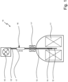
Fig. 1 schematically depicts a transfer device for shuttling a Nuclear Magnetic Resonance (=NMR)sample container 12 between at least two coaxially arranged NMR magnet systems 11'; 11" of anNMR spectrometer 10, in particular a high-field NMR magnet system11' and a low-fieldNMR magnet system 11". The transfer device comprises aguide tube 13 positioned in a central bore of the coaxial magnet systems 11'; 11", ashuttle assembly 14 being arranged inside theguide tube 13 for securely holding and shuttling theNMR sample container 12 and a drive system comprising a pulling drive 15' and awinch cord 15" being attached to the drive system on one side and to theshuttle assembly 14 on the other side, such that theshuttle assembly 14 can travel inside theguide tube 13 between the coaxial magnet systems 11'; 11". - The pulling drive 15' of the drive system may comprise a cable winch, which is equipped with a rotating mechanism. The rotating mechanism can be driven by a servo motor or a stepper motor (not shown in the drawings). The servo motor or stepper motor can be calibrated for the number of steps being performed between two measuring positions within the NMR magnet systems 11'; 11", the distance between the upper and the lower measuring position being recorded by determining the appropriate number of steps.
- The transfer device according to the invention is characterized by a pneumatic pressurizing arrangement with an
entry 16 for pressurized gas arranged on a gas-tight body 17 above theshuttle assembly 14 being adapted to maintain thewinch cord 15" under tension, and by ashuttle assembly 14 comprising a piston design being moveable along the common axis of the coaxial magnet systems 11'; 11" under the influence of the pressure. - In
Fig. 1 , thewhole shuttle assembly 14 with theguide tube 13 and a drive mechanism is shown schematically being implemented in a two-field NMR device. The shuttle is attached by thewinch cord 15" and it can be moved between a high field position, a low field position and a changing position where the shuttle is located inside a gas-tight exchange station 20 as shown inFigs. 2 and3 . Pressurized gas is fed via the changing station to keep the winch cord under tension. - The
shuttle assembly 14 comprises a piston fitting into theguide tube 13 with an outer circumference so that it can move in it without friction. The friction between the shuttle and the guide tube is reduced by the fact, that the compressed air can flow circumferentially past the shuttle, thus creating an air cushion between theguide tube 13 and the central bore of the coaxial magnet systems 11'; 11". In the present design, the distance to the wall of the guide tube is only 10 to 50 µm so that a flow of approximately 10 standard liters per minute is created between the wall of theguide tube 13 and the shuttle when a pressure of 3 to 6 bar is applied. - This gas flow is used in preferred embodiments to temper the sample in the
sample container 12. The gas is therefore preset to a desired temperature. - As shown in the schematic cut-away view of
Fig. 2 depicting the gas-tight exchange station 20 being part of the transfer device according to the invention, anair gap 18 is provided between theshuttle piston 14 and the inner wall of theguide tube 13. Theair gap 18 may amounts from 10µm and 50µm. - Preferably, the pressure gas connection with the
entry 16 is located at the non-movable component of theexchange station 20, whereby the gas flow can also be opened and closed there, either manually with a gas cock, or with a mechanically releasable shutter valve. - Usually, the
guide tube 13 is made of glass. As indicated inFig. 2 , theguide tube 13 in its lower part may comprise a drilled hole 13' in a cylindrical aluminum component that also can contain a gas inlet. -
Fig. 3 shows an embodiment of the transfer device according to the invention with the pulling drive 15' of the drive system in the shape of a cable winch, theexchange station 20 and theshuttle assembly 14 therein. Being integrated into anNMR spectrometer 10 in a space-saving manner, the transfer device is capable of moving anNMR sample tube 12, which is fastened to the shuttle, precisely between at least two adjustable measuring positions in less than 100ms. - The basic idea was to design the shuttle as a pneumatic piston, which is guided in a tube made of dielectric material, so that it is pushed down with compressed air with the movement being controlled by a cable winch. As alternative embodiments (not shown here), a swing-arm or a cam can be used instead of a winch. The
winch cord 15" is always kept under tension by the constantly applied gas pressure, allowing the shuttle to be precisely positioned with the pulling drive 15'. Since the moving parts have relatively low masses, significantly higher accelerations and speeds can be achieved than with belt-driven or rail-guided systems. Due to the central introduction of force by the cord pull or compressed air, no bearing forces are generated, so the system is subject to little wear and thus has a long service life. The shuttle is designed to fit in the tube with a narrow gap between the shuttle and theguide tube 13 thus allowing the formation of an air bearing or air cushion. The airflow between the shuttle/NMR-tube and the wall of theguide tube 13 is well calibrated and it can be used for tempering the sample. - The presented shuttle system allows a
sample container 12 to move rapidly in a couple of milliseconds between two position. The filling factor inside the magnet bore is very low as it only uses a glass tube having an inner diameter which corresponds to thesample container 12 plus the surroundingair gap 18. The whole kinematic structure is localized inside theguide tube 13 of about 10mm in diameter. - The number of pieces and the geometry is minimalized as it requires only a (nylon) cable and a tube. The state-of-the-art solutions are more space demanding.
- The pulling drive 15' and the changing
station 20, which are arranged above the magnet systems 11'; 11", have a compact geometry such that there is generally no inconvenience for an installation in laboratories with a standard ceiling height. - The system can easily be adapted to existing NMR spectrometers without any modification in the magnet bore.
- Preferably, the
NMR sample container 12 is maintained by the shuttle by force fitting elements such as a series of O-rings, which are positioned in a gap of the shuttle. The shuttle is designed to fit into the opening of asample container 12. The friction force between the shuttle and thesample container 12 surfaces are designed to be sufficient for the high acceleration and deceleration of thesample container 12. - The piston is guided and sealed by a high-precision borosilicate glass tube which runs from the changing station (air lock) on the magnet to just above the high-field sample head in the magnet, where it ends in a centering end stop. Especially for use in 2F-NMR, the use of a quartz glass tube as a guide element is advantageous compared to a conventional linear slide, since its symmetrical geometry and material have a comparatively small effect on the measurement in the upper (low-field) sample head.
- The shuttle is adapted to move in the
guide tube 13 between an upper (low field) and a lower (high field) measuring position. For that the connection to the pressurized air or gas is arranged above the piston in its upper position and arranged such that the cord which is attached to the shuttle is kept under tension. For sealing effectiveness, the transfer device comprises pressurized system components with sealing carried out on the drive shaft. The connection to the pressurized gas is either at the gas tight cable winch or at the changingstation 20. The advantage of these gas entry arrangements is that the box of the cable winch and the changingstation 20 serves as a gas chamber providing a reservoir of pressurized gas which limits variations in pressure and gas temperature (= buffer volume). However, the motor can produce heat which could change the gas temperature. So the entry via the box of the cable winch is less preferred. - The changing
station 20 is arranged between theguide tube 13 and the pulling drive 15', above the upper measuring position. To change thesample container 12, the changingstation 20 is depressurized, e.g. by closing a valve for gas inlet, and the shuttle is driven to an uppermost position. In this position, the changing station can be opened by the user to change theNMR sample container 12. In a preferred embodiment, the changingstation 20 is surrounded by a generally cylindrical jacket, which is movable from a first position in which the changing station is closed and gas tight, to a second position in which the changing station is open and the shuttle with thesample container 12 is accessible to the user such that thesample container 12 can be changed. The shuttle exchange is executed in unpressurized condition with the cable / rope pretension is provided by a spring-loaded mechanism. - The system is supplied with pressurized gas (e.g. compressed air connection 6bar, even better: nitrogen) and with power from the socket (220V). The motor control preferably of a servo motor communicates with the spectrometer software ("TopSpin") via a data interface (e.g. CAN-Bus, Ethernet, USB). The software connection and the motor control correspond to the state of the art and comparable systems are used to control belt-driven shuttle systems.
- In some embodiments, the pressurized gas is heated or cooled to the desired measurement temperature. In this way the sample temperature can be adjusted by using leaking piston drive gas flow. To make the tempering more efficient, the piston can be provided with through holes thus increasing the gas flow around the
NMR sample container 12. - In
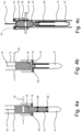
Figures 4a to 4c , various embodiments of the transfer device according to the invention are shown, each having end stopfacilities 19 for theshuttle assembly 14. - The
end stop 19 is vibration damping in high field position and comprises abutment surfaces 19', 19" between theshuttle assembly 14 and a protrusion at the end of theguide tube 13. The abutment surfaces 19', 19" are chamfered for centering theNMR sample container 12 in the field of view when theshuttle assembly 14 is in its end stop position. - The abutment surface 19' arranged in the
guide tube 13 is helpful to precisely position theshuttle assembly 14. By using a stepper motor or a servo motor the distance between the upper and the lower measuring positions can be recorded or determined to adjust the number of steps that the motor performs between both positions. - As can be seen in the
Figures 4a-c , theshuttle assembly 14 is provided with several projections that serve as abutment surfaces to position the shuttle in an exact end stop position in the high field range of the magnet. As a counterpart, a holder with a circumferential, preferably beveled end stop is arranged below theguide tube 13, on which the shuttle rests when theNMR sample container 12 is in the measuring position. The holder is fixedly arranged at the lower end of theguide tube 13. TheNMR sample container 12 with the sample protrudes from the holder into the homogeneous area of the magnet (FOV). - The shuttle is designed in such a way that it fits into a standardized
NMR sample container 12 with a diameter of 5mm, with -at least two- O-rings 28 to provide a tight compression fitting to theNMR sample container 12. - Alternatively, holding
elements 24 can be attached or glued to theNMR sample container 12, the holdingelements 24 comprising for example a screw thread to which the shuttle can be screwed. - A
detector element 30 is arranged to measure the exact end stop position of theshuttle assembly 14 in the magnetic fields, to ensure that thesample container 12 is precisely positioned in the homogenous B0 field in the lower position. A light barrier or a photo sensor transmitting light through theguide tube 13, when theshuttle assembly 14 is in its correct end stop position in the B0 field. - Furthermore, the
shuttle assembly 14 may have a transparent area (e.g. thewindow 25 as depicted inFig. 4c ) through which the end position is detected by means of light guides positioned in the holder. The light guides are connected to a photo sensor. This sensor technology using photo sensors makes it possible to trigger the measurement via an interface in the operating software as soon as the shuttle has arrived at the measuring position. This feature allows the execution of very fast measuring cycles. - The schematic vertical cross section through a high field NMR magnet system 11' shown in
Fig.5 illustrates essential parts of the transfer device according to the invention, which are partly arranged inside the magnet bore. - The
guide tube 13 is radially fixed by bumper fastenings or dampeningbrackets 21, which retain the guide tube inside the magnet bore and reduce significantly the vibrations and consequently also the friction and the wear of the system. Thereby the maximum radial vibration amplitude can be constrained to less than the air gap dimension. -
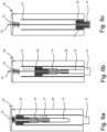
Figures 6a to 6c show schematic vertical cross sections through embodiments of theexchange station 20, namely - (a) in an upper position of the shuttle for opening,
- (b) in an intermediate position of the shuttle, and
- (c) in a closed position.
- The changing
station 20 is located at the upper end of theguide tube 13. Instead of a window 25 (as shown inFigure 3 ), the gas-tight exchange station 20 can comprise a door or a movable sleeve 26 (as shown inFigures 6a and 6b ) to access theshuttle assembly 14. This sleeve tube can be moved in the Z-direction and in a first position encloses theguide tube 13 in a gas-tight manner. The sleeve tube can be pushed into a second position, which gives access to theNMR sample container 12. In the area of the changingstation 20, theguide tube 13 is designed to be half-open or extended by a semicircular guide so that theNMR sample container 12 can easily be removed. - It is also important that the
shuttle assembly 14 is well centralized inside the guidingtube 13. For this purpose, a centeringdevice 22 is arranged on the upper end of theguide tube 13 for aligning thewinch cord 15" inside theguide tube 13 as shown inFigure 6c . In the embodiment offigures 6 a-c , the centeringdevice 22 is movable from the lower position in which the centering device is arranged in theguide tube 13. In this embodiment, the centering device is combined with a weight element for keeping the rope under tension when theshuttle assembly 14 travels inside the changingstation 20 from the lower to the uppermost position where the resilient element (here spring 23) is arranged. The weight element is engaged to guiderails 27 for allowing a controlled movement of the shuttle assembly together with the centeringdevice 22 and for a precise re-insertion of the centeringdevice 22 inside theguide tube 13 after theNMR sample container 12 has been changed.. The main function of the centeringdevice 22 is to perfectly axially center the rope inguide tube 13. There is no tilting moment of the shuttle due to non-axial rope force. This also prevents vibration, wear and free swing of the NMR sample container end protruding into the probehead. - The centering
device 22 can also be attached separately from the weight element (not shown infigures 6 ) to the upper end of theguide tube 13 at the lower end of the exchange station. The centeringdevice 22 also prevents vibration excitation at theguide tube 13 due to the fast movement of theshuttle assembly 14. - A stop for the
shuttle assembly 14 is attached to the upper part of theguide tube 13, which is preferably pre-tensioned by aspring 23, so that thecord 15" remains under tension while the gas flow is interrupted. -
Guide rails 27 arranged within theexchange station 20 may also help to centralize theshuttle assembly 14 inside the guidingtube 13. -
- 10
- NMR spectrometer
- 11'
- high-field NMR magnet system
- 11"
- low-field NMR magnet system
- 12
- NMR sample container
- 13
- guide tube
- 13'
- drilled hole
- 14
- shuttle assembly
- 15'
- pulling drive
- 15"
- winch cord
- 16
- entry for pressurized gas
- 17
- gas-tight body
- 18
- air gap
- 19
- end stop
- 19', 19"
- abutment surfaces
- 20
- gas-tight exchange station
- 21
- dampening brackets
- 22
- centering device
- 23
- spring
- 24
- holding element
- 25
- window
- 26
- sleeve
- 27
- guide rails
- 28
- O-rings
- 30
- detector element
- Publications considered for assessing patentability of the present invention:
- [1] Andrew M.R. Hall et al, "A temperature-controlled sample shuttle for field-cycling NMR", Journal of Magnetic Resonance 317 (2020) 106778
- [2]
EP 3 081 954 B1 - [3] Alfred G. Redfield, "Shuttling device for high-resolution measurements of relaxation and related phenomena in solution at low field, using a shared commercial 500 MHz NMR instrument", Magn. Reson. Chem. 2003; 41: 753-768
- [4] Alfred G. Redfield, "High-resolution NMR field-cycling device for full-range relaxation and structural studies of biopolymers on a shared commercial instrument", J. Biomol NMR (2012) 52:159-177
- [5]
US 9,696,391 B2 - [6]
EP 2 610 631 B1 - [7]
US 4,859,949 A
Claims (15)
- Transfer device for shuttling a Nuclear Magnetic Resonance (=NMR) sample container (12) between at least two coaxially arranged NMR magnet systems (11'; 11") of an NMR spectrometer (10), the transfer device comprising a guide tube (13) configured to be positioned in a central bore of the coaxial magnet systems (11'; 11"), a shuttle assembly (14) being arranged inside the guide tube (13) for securely holding and shuttling the NMR sample container (12) and a drive system comprising a pulling drive (15') and a winch cord (15") being attached to the drive system on one side and to the shuttle assembly (14) on the other side, such that the shuttle assembly (14) can travel inside the guide tube (13) between the coaxial magnet systems (11'; 11"),
characterized inthat the transfer device comprises a gas-tight body (17) above the shuttle assembly (14) and a pneumatic pressurizing arrangement with an entry (16) for pressurized gas arranged on the gas-tight body (17) for maintaining the winch cord (15") under tension,and that the shuttle assembly (14) comprises a piston design being moveable along the common axis of the coaxial magnet systems (11'; 11") under the influence of the pressure. - Transfer device according to claim 1, characterized in that an air gap (18) is provided between the shuttle piston and the inner wall of the guide tube (13).
- Transfer device according to claim 2, characterized in that the air gap (18) amounts from 10µm to 50µm.
- Transfer device according to anyone of the preceding claims, characterized in that the pulling drive (15') of the drive system comprises a cable winch, which is equipped with a rotating mechanism.
- Transfer device according to claim 4, characterized in that the rotating mechanism is driven by a servo motor or a stepper motor.
- Transfer device according to claim 5, characterized in that the servo motor or stepper motor is calibrated for the number of steps being performed between two measuring positions within the NMR magnet systems (11'; 11"), the distance between the upper and the lower measuring position being recorded by determining the appropriate number of steps.
- Transfer device according to anyone of the preceding claims, characterized in that an end stop (19) being vibration damping in high field position comprises an abutment surface (19', 19") between the shuttle assembly (14) and a protrusion at the end of the guide tube (13).
- Transfer device according to claim 5, characterized in that the abutment surface (19', 19") is chamfered for centering the NMR sample container (12) in its end stop position.
- Transfer device according to anyone of the preceding claims, characterized in that a gas-tight exchange station (20) comprises a window (25), a movable sleeve (26) or a door to access the shuttle assembly (14).
- Transfer device according to anyone of the preceding claims, characterized in that a detector element (30) is arranged to measure the end stop position of the shuttle assembly (14) in the magnetic fields.
- Transfer device according to claim 8, characterized in that the detector element (30) comprises a light barrier transmitting light through the guide tube (13), when the shuttle assembly (14) is in its end stop position.
- Transfer device according to anyone of the preceding claims, characterized in that the guide tube (13) is radially fixed by bumper fastenings or dampening brackets (21) that constraint the maximum radial vibration amplitude to less than air gap dimension.
- Transfer device according to anyone of the preceding claims, characterized in that a centering device (22) is arranged on the upper end of the guide tube (13) for aligning the winch cord (15") inside the guide tube (13).
- Transfer device according to anyone of the preceding claims, characterized in that the diameter of the guide tube (13) is from 3mm to 15mm.
- Nuclear Magnetic Resonance spectrometer (10) adapted for performing field-cycling techniques including two-field NMR (="2F-NMR"), with at least two coaxially arranged NMR magnet systems (11'; 11") for generating different magnetic fields comprising a transfer device according to anyone of the claims 1 to 12.
Priority Applications (5)
| Application Number | Priority Date | Filing Date | Title |
|---|---|---|---|
| EP21167449.4A EP4071492B1 (en) | 2021-04-08 | 2021-04-08 | Pneumatic cable shuttle system for 2fnmr |
| EP22167026.8A EP4071493B1 (en) | 2021-04-08 | 2022-04-06 | Shuttle assembly for 2fnmr |
| US17/715,299 US11474172B1 (en) | 2021-04-08 | 2022-04-07 | Pneumatic cable shuttle system for 2FNMR |
| CN202210366054.4A CN115201728B (en) | 2021-04-08 | 2022-04-08 | Pneumatic cable shuttle system for dual field nuclear magnetic resonance |
| JP2022001128U JP3238709U (en) | 2021-04-08 | 2022-04-08 | Pneumatic cable shuttle system for 2F-NMR |
Applications Claiming Priority (1)
| Application Number | Priority Date | Filing Date | Title |
|---|---|---|---|
| EP21167449.4A EP4071492B1 (en) | 2021-04-08 | 2021-04-08 | Pneumatic cable shuttle system for 2fnmr |
Publications (2)
| Publication Number | Publication Date |
|---|---|
| EP4071492A1 EP4071492A1 (en) | 2022-10-12 |
| EP4071492B1 true EP4071492B1 (en) | 2023-03-29 |
Family
ID=75438653
Family Applications (2)
| Application Number | Title | Priority Date | Filing Date |
|---|---|---|---|
| EP21167449.4A Active EP4071492B1 (en) | 2021-04-08 | 2021-04-08 | Pneumatic cable shuttle system for 2fnmr |
| EP22167026.8A Active EP4071493B1 (en) | 2021-04-08 | 2022-04-06 | Shuttle assembly for 2fnmr |
Family Applications After (1)
| Application Number | Title | Priority Date | Filing Date |
|---|---|---|---|
| EP22167026.8A Active EP4071493B1 (en) | 2021-04-08 | 2022-04-06 | Shuttle assembly for 2fnmr |
Country Status (4)
| Country | Link |
|---|---|
| US (1) | US11474172B1 (en) |
| EP (2) | EP4071492B1 (en) |
| JP (1) | JP3238709U (en) |
| CN (1) | CN115201728B (en) |
Cited By (1)
| Publication number | Priority date | Publication date | Assignee | Title |
|---|---|---|---|---|
| EP4530651A1 (en) | 2023-09-26 | 2025-04-02 | Bruker France S.A.S. | Fast switch field combined nmr device for 2fnmr |
Families Citing this family (1)
| Publication number | Priority date | Publication date | Assignee | Title |
|---|---|---|---|---|
| CN120891214B (en) * | 2025-09-30 | 2025-12-09 | 中国人民解放军空军军医大学 | An automatic sample introduction device for nuclear magnetic resonance spectrometer |
Family Cites Families (9)
| Publication number | Priority date | Publication date | Assignee | Title |
|---|---|---|---|---|
| US4859949A (en) | 1988-01-26 | 1989-08-22 | Siemens Aktiengesellschaft | Magnetic resonance spectroscopy apparatus |
| GB2498181A (en) | 2011-12-29 | 2013-07-10 | Bruker Biospin Gmbh | Device and method for rapid dynamic nuclear polarisation |
| US9696391B2 (en) | 2012-05-07 | 2017-07-04 | Academia Sinica | High speed sample transportation apparatus in a superconducting magnet and transporting method thereof |
| DE102014201076B3 (en) * | 2014-01-22 | 2015-03-05 | Bruker Biospin Ag | Transport container for an NMR MAS rotor |
| EP3081954B1 (en) | 2015-04-13 | 2018-07-25 | Bruker France S.A.S. | Method for two field nuclear magnetic resonance measurements |
| CN104807848B (en) * | 2015-05-15 | 2017-02-01 | 中国科学院武汉物理与数学研究所 | Device and method for positioning and sample feeding of low-field magnetism resonance system |
| DE102017212192B3 (en) * | 2017-07-17 | 2018-10-18 | Bruker Biospin Ag | Transport device for an NMR MAS rotor into a probe head ("MAS Shuttle") |
| US11531076B2 (en) * | 2017-11-03 | 2022-12-20 | The Regents Of The University Of California | Wide dynamic range magnetic field cycler and ultra portable optical nanodiamond hyperpolarizer |
| EP3715893B1 (en) * | 2019-03-25 | 2021-02-24 | Bruker Switzerland AG | Nmr spectrometer with quick swap system for samples |
-
2021
- 2021-04-08 EP EP21167449.4A patent/EP4071492B1/en active Active
-
2022
- 2022-04-06 EP EP22167026.8A patent/EP4071493B1/en active Active
- 2022-04-07 US US17/715,299 patent/US11474172B1/en active Active
- 2022-04-08 JP JP2022001128U patent/JP3238709U/en active Active
- 2022-04-08 CN CN202210366054.4A patent/CN115201728B/en active Active
Cited By (1)
| Publication number | Priority date | Publication date | Assignee | Title |
|---|---|---|---|---|
| EP4530651A1 (en) | 2023-09-26 | 2025-04-02 | Bruker France S.A.S. | Fast switch field combined nmr device for 2fnmr |
Also Published As
| Publication number | Publication date |
|---|---|
| US20220326323A1 (en) | 2022-10-13 |
| EP4071493A1 (en) | 2022-10-12 |
| EP4071492A1 (en) | 2022-10-12 |
| CN115201728A (en) | 2022-10-18 |
| EP4071493B1 (en) | 2024-02-28 |
| US11474172B1 (en) | 2022-10-18 |
| CN115201728B (en) | 2023-07-25 |
| JP3238709U (en) | 2022-08-15 |
Similar Documents
| Publication | Publication Date | Title |
|---|---|---|
| US11474172B1 (en) | Pneumatic cable shuttle system for 2FNMR | |
| US6686740B2 (en) | Device for the transport and exact positioning of a sample tube in a high-resolution NMR spectrometer | |
| US7535224B2 (en) | Discrete magic angle turning system, apparatus, and process for in situ magnetic resonance spectroscopy and imaging | |
| US5635840A (en) | Apparatus including sample support member for support and isolation of a sample transfer device and RF detection unit from the static and gradient coils | |
| US10261143B2 (en) | Probehead with adjustable angle for NMR-MAS apparatus | |
| US9696391B2 (en) | High speed sample transportation apparatus in a superconducting magnet and transporting method thereof | |
| EP3717924B1 (en) | Spherical rotors and their use in nmr spectroscopy | |
| US5220302A (en) | Nmr clinical chemistry analyzer and method of forming a shield | |
| Villanueva-Garibay et al. | A fast sample shuttle to couple high and low magnetic fields. Applications to high-resolution relaxometry | |
| US5323136A (en) | Electromagnetic apparatus | |
| US11073579B1 (en) | Magnetically compensated NMR rotor | |
| US6414491B1 (en) | Axial sample conveyer | |
| CN119213328B (en) | Device for holding NMR measurement samples in a spatially limited NMR spectrometer | |
| CN109814051B (en) | Magic angle rotating nuclear magnetic resonance probe assembly with replaceable stator | |
| JP4073379B2 (en) | Solid state NMR probe | |
| EP4530651B1 (en) | Fast switch field combined nmr device for 2fnmr | |
| US20080036461A1 (en) | Method for improving the precision of time domain low field h-nmr analysis | |
| KR101487160B1 (en) | Apparatus of magnetic resonance force microscope for biological sample | |
| JP4319641B2 (en) | NMR apparatus and measurement method thereof | |
| Luchinat | A fast sample shuttle to couple high and low magnetic fields. Applications to high-resolution relaxometry | |
| Lee et al. | MEMS-based force-detected nuclear magnetic resonance (FDNMR) spectrometer |
Legal Events
| Date | Code | Title | Description |
|---|---|---|---|
| PUAI | Public reference made under article 153(3) epc to a published international application that has entered the european phase |
Free format text: ORIGINAL CODE: 0009012 |
|
| STAA | Information on the status of an ep patent application or granted ep patent |
Free format text: STATUS: REQUEST FOR EXAMINATION WAS MADE |
|
| 17P | Request for examination filed |
Effective date: 20211104 |
|
| AK | Designated contracting states |
Kind code of ref document: A1 Designated state(s): AL AT BE BG CH CY CZ DE DK EE ES FI FR GB GR HR HU IE IS IT LI LT LU LV MC MK MT NL NO PL PT RO RS SE SI SK SM TR |
|
| RIC1 | Information provided on ipc code assigned before grant |
Ipc: G01R 33/44 20060101ALN20221025BHEP Ipc: G01R 33/30 20060101AFI20221025BHEP |
|
| GRAP | Despatch of communication of intention to grant a patent |
Free format text: ORIGINAL CODE: EPIDOSNIGR1 |
|
| STAA | Information on the status of an ep patent application or granted ep patent |
Free format text: STATUS: GRANT OF PATENT IS INTENDED |
|
| INTG | Intention to grant announced |
Effective date: 20221209 |
|
| GRAS | Grant fee paid |
Free format text: ORIGINAL CODE: EPIDOSNIGR3 |
|
| GRAA | (expected) grant |
Free format text: ORIGINAL CODE: 0009210 |
|
| STAA | Information on the status of an ep patent application or granted ep patent |
Free format text: STATUS: THE PATENT HAS BEEN GRANTED |
|
| REG | Reference to a national code |
Ref country code: DE Ref legal event code: R083 Ref document number: 602021001711 Country of ref document: DE |
|
| AK | Designated contracting states |
Kind code of ref document: B1 Designated state(s): AL AT BE BG CH CY CZ DE DK EE ES FI FR GB GR HR HU IE IS IT LI LT LU LV MC MK MT NL NO PL PT RO RS SE SI SK SM TR |
|
| REG | Reference to a national code |
Ref country code: CH Ref legal event code: EP |
|
| RIN2 | Information on inventor provided after grant (corrected) |
Inventor name: TYBURN, JEAN-MAX Inventor name: MARQUARDSEN, THORSTEN Inventor name: TILCH, ANDREAS Inventor name: ADERS, PHILIPP |
|
| REG | Reference to a national code |
Ref country code: DE Ref legal event code: R096 Ref document number: 602021001711 Country of ref document: DE |
|
| REG | Reference to a national code |
Ref country code: AT Ref legal event code: REF Ref document number: 1557073 Country of ref document: AT Kind code of ref document: T Effective date: 20230415 |
|
| REG | Reference to a national code |
Ref country code: IE Ref legal event code: FG4D |
|
| REG | Reference to a national code |
Ref country code: LT Ref legal event code: MG9D |
|
| PG25 | Lapsed in a contracting state [announced via postgrant information from national office to epo] |
Ref country code: RS Free format text: LAPSE BECAUSE OF FAILURE TO SUBMIT A TRANSLATION OF THE DESCRIPTION OR TO PAY THE FEE WITHIN THE PRESCRIBED TIME-LIMIT Effective date: 20230329 Ref country code: NO Free format text: LAPSE BECAUSE OF FAILURE TO SUBMIT A TRANSLATION OF THE DESCRIPTION OR TO PAY THE FEE WITHIN THE PRESCRIBED TIME-LIMIT Effective date: 20230629 Ref country code: LV Free format text: LAPSE BECAUSE OF FAILURE TO SUBMIT A TRANSLATION OF THE DESCRIPTION OR TO PAY THE FEE WITHIN THE PRESCRIBED TIME-LIMIT Effective date: 20230329 Ref country code: LT Free format text: LAPSE BECAUSE OF FAILURE TO SUBMIT A TRANSLATION OF THE DESCRIPTION OR TO PAY THE FEE WITHIN THE PRESCRIBED TIME-LIMIT Effective date: 20230329 Ref country code: HR Free format text: LAPSE BECAUSE OF FAILURE TO SUBMIT A TRANSLATION OF THE DESCRIPTION OR TO PAY THE FEE WITHIN THE PRESCRIBED TIME-LIMIT Effective date: 20230329 |
|
| REG | Reference to a national code |
Ref country code: NL Ref legal event code: MP Effective date: 20230329 |
|
| REG | Reference to a national code |
Ref country code: AT Ref legal event code: MK05 Ref document number: 1557073 Country of ref document: AT Kind code of ref document: T Effective date: 20230329 |
|
| PG25 | Lapsed in a contracting state [announced via postgrant information from national office to epo] |
Ref country code: SE Free format text: LAPSE BECAUSE OF FAILURE TO SUBMIT A TRANSLATION OF THE DESCRIPTION OR TO PAY THE FEE WITHIN THE PRESCRIBED TIME-LIMIT Effective date: 20230329 Ref country code: NL Free format text: LAPSE BECAUSE OF FAILURE TO SUBMIT A TRANSLATION OF THE DESCRIPTION OR TO PAY THE FEE WITHIN THE PRESCRIBED TIME-LIMIT Effective date: 20230329 Ref country code: GR Free format text: LAPSE BECAUSE OF FAILURE TO SUBMIT A TRANSLATION OF THE DESCRIPTION OR TO PAY THE FEE WITHIN THE PRESCRIBED TIME-LIMIT Effective date: 20230630 Ref country code: FI Free format text: LAPSE BECAUSE OF FAILURE TO SUBMIT A TRANSLATION OF THE DESCRIPTION OR TO PAY THE FEE WITHIN THE PRESCRIBED TIME-LIMIT Effective date: 20230329 |
|
| PG25 | Lapsed in a contracting state [announced via postgrant information from national office to epo] |
Ref country code: SM Free format text: LAPSE BECAUSE OF FAILURE TO SUBMIT A TRANSLATION OF THE DESCRIPTION OR TO PAY THE FEE WITHIN THE PRESCRIBED TIME-LIMIT Effective date: 20230329 Ref country code: RO Free format text: LAPSE BECAUSE OF FAILURE TO SUBMIT A TRANSLATION OF THE DESCRIPTION OR TO PAY THE FEE WITHIN THE PRESCRIBED TIME-LIMIT Effective date: 20230329 Ref country code: PT Free format text: LAPSE BECAUSE OF FAILURE TO SUBMIT A TRANSLATION OF THE DESCRIPTION OR TO PAY THE FEE WITHIN THE PRESCRIBED TIME-LIMIT Effective date: 20230731 Ref country code: ES Free format text: LAPSE BECAUSE OF FAILURE TO SUBMIT A TRANSLATION OF THE DESCRIPTION OR TO PAY THE FEE WITHIN THE PRESCRIBED TIME-LIMIT Effective date: 20230329 Ref country code: EE Free format text: LAPSE BECAUSE OF FAILURE TO SUBMIT A TRANSLATION OF THE DESCRIPTION OR TO PAY THE FEE WITHIN THE PRESCRIBED TIME-LIMIT Effective date: 20230329 Ref country code: AT Free format text: LAPSE BECAUSE OF FAILURE TO SUBMIT A TRANSLATION OF THE DESCRIPTION OR TO PAY THE FEE WITHIN THE PRESCRIBED TIME-LIMIT Effective date: 20230329 |
|
| PG25 | Lapsed in a contracting state [announced via postgrant information from national office to epo] |
Ref country code: SK Free format text: LAPSE BECAUSE OF FAILURE TO SUBMIT A TRANSLATION OF THE DESCRIPTION OR TO PAY THE FEE WITHIN THE PRESCRIBED TIME-LIMIT Effective date: 20230329 Ref country code: PL Free format text: LAPSE BECAUSE OF FAILURE TO SUBMIT A TRANSLATION OF THE DESCRIPTION OR TO PAY THE FEE WITHIN THE PRESCRIBED TIME-LIMIT Effective date: 20230329 Ref country code: IS Free format text: LAPSE BECAUSE OF FAILURE TO SUBMIT A TRANSLATION OF THE DESCRIPTION OR TO PAY THE FEE WITHIN THE PRESCRIBED TIME-LIMIT Effective date: 20230729 |
|
| P01 | Opt-out of the competence of the unified patent court (upc) registered |
Effective date: 20231030 |
|
| PG25 | Lapsed in a contracting state [announced via postgrant information from national office to epo] |
Ref country code: LU Free format text: LAPSE BECAUSE OF NON-PAYMENT OF DUE FEES Effective date: 20230408 |
|
| REG | Reference to a national code |
Ref country code: DE Ref legal event code: R097 Ref document number: 602021001711 Country of ref document: DE |
|
| REG | Reference to a national code |
Ref country code: BE Ref legal event code: MM Effective date: 20230430 |
|
| PG25 | Lapsed in a contracting state [announced via postgrant information from national office to epo] |
Ref country code: MC Free format text: LAPSE BECAUSE OF FAILURE TO SUBMIT A TRANSLATION OF THE DESCRIPTION OR TO PAY THE FEE WITHIN THE PRESCRIBED TIME-LIMIT Effective date: 20230329 |
|
| PG25 | Lapsed in a contracting state [announced via postgrant information from national office to epo] |
Ref country code: MC Free format text: LAPSE BECAUSE OF FAILURE TO SUBMIT A TRANSLATION OF THE DESCRIPTION OR TO PAY THE FEE WITHIN THE PRESCRIBED TIME-LIMIT Effective date: 20230329 Ref country code: DK Free format text: LAPSE BECAUSE OF FAILURE TO SUBMIT A TRANSLATION OF THE DESCRIPTION OR TO PAY THE FEE WITHIN THE PRESCRIBED TIME-LIMIT Effective date: 20230329 Ref country code: CZ Free format text: LAPSE BECAUSE OF FAILURE TO SUBMIT A TRANSLATION OF THE DESCRIPTION OR TO PAY THE FEE WITHIN THE PRESCRIBED TIME-LIMIT Effective date: 20230329 |
|
| PLBE | No opposition filed within time limit |
Free format text: ORIGINAL CODE: 0009261 |
|
| STAA | Information on the status of an ep patent application or granted ep patent |
Free format text: STATUS: NO OPPOSITION FILED WITHIN TIME LIMIT |
|
| REG | Reference to a national code |
Ref country code: IE Ref legal event code: MM4A |
|
| PG25 | Lapsed in a contracting state [announced via postgrant information from national office to epo] |
Ref country code: BE Free format text: LAPSE BECAUSE OF NON-PAYMENT OF DUE FEES Effective date: 20230430 |
|
| 26N | No opposition filed |
Effective date: 20240103 |
|
| PG25 | Lapsed in a contracting state [announced via postgrant information from national office to epo] |
Ref country code: IE Free format text: LAPSE BECAUSE OF NON-PAYMENT OF DUE FEES Effective date: 20230408 |
|
| PG25 | Lapsed in a contracting state [announced via postgrant information from national office to epo] |
Ref country code: IE Free format text: LAPSE BECAUSE OF NON-PAYMENT OF DUE FEES Effective date: 20230408 |
|
| PG25 | Lapsed in a contracting state [announced via postgrant information from national office to epo] |
Ref country code: SI Free format text: LAPSE BECAUSE OF FAILURE TO SUBMIT A TRANSLATION OF THE DESCRIPTION OR TO PAY THE FEE WITHIN THE PRESCRIBED TIME-LIMIT Effective date: 20230329 |
|
| PG25 | Lapsed in a contracting state [announced via postgrant information from national office to epo] |
Ref country code: SI Free format text: LAPSE BECAUSE OF FAILURE TO SUBMIT A TRANSLATION OF THE DESCRIPTION OR TO PAY THE FEE WITHIN THE PRESCRIBED TIME-LIMIT Effective date: 20230329 Ref country code: IT Free format text: LAPSE BECAUSE OF FAILURE TO SUBMIT A TRANSLATION OF THE DESCRIPTION OR TO PAY THE FEE WITHIN THE PRESCRIBED TIME-LIMIT Effective date: 20230329 |
|
| REG | Reference to a national code |
Ref country code: GB Ref legal event code: 732E Free format text: REGISTERED BETWEEN 20240829 AND 20240904 |
|
| PG25 | Lapsed in a contracting state [announced via postgrant information from national office to epo] |
Ref country code: BG Free format text: LAPSE BECAUSE OF FAILURE TO SUBMIT A TRANSLATION OF THE DESCRIPTION OR TO PAY THE FEE WITHIN THE PRESCRIBED TIME-LIMIT Effective date: 20230329 |
|
| PG25 | Lapsed in a contracting state [announced via postgrant information from national office to epo] |
Ref country code: BG Free format text: LAPSE BECAUSE OF FAILURE TO SUBMIT A TRANSLATION OF THE DESCRIPTION OR TO PAY THE FEE WITHIN THE PRESCRIBED TIME-LIMIT Effective date: 20230329 |
|
| REG | Reference to a national code |
Ref country code: DE Ref legal event code: R081 Ref document number: 602021001711 Country of ref document: DE Owner name: BRUKER BIOSPIN GMBH & CO. KG, DE Free format text: FORMER OWNER: BRUKER BIOSPIN GMBH, 76275 ETTLINGEN, DE |
|
| PGFP | Annual fee paid to national office [announced via postgrant information from national office to epo] |
Ref country code: DE Payment date: 20250417 Year of fee payment: 5 |
|
| PGFP | Annual fee paid to national office [announced via postgrant information from national office to epo] |
Ref country code: GB Payment date: 20250423 Year of fee payment: 5 |
|
| PGFP | Annual fee paid to national office [announced via postgrant information from national office to epo] |
Ref country code: FR Payment date: 20250422 Year of fee payment: 5 |
|
| PGFP | Annual fee paid to national office [announced via postgrant information from national office to epo] |
Ref country code: CH Payment date: 20250501 Year of fee payment: 5 |
|
| PG25 | Lapsed in a contracting state [announced via postgrant information from national office to epo] |
Ref country code: CY Free format text: LAPSE BECAUSE OF FAILURE TO SUBMIT A TRANSLATION OF THE DESCRIPTION OR TO PAY THE FEE WITHIN THE PRESCRIBED TIME-LIMIT; INVALID AB INITIO Effective date: 20210408 |
|
| PG25 | Lapsed in a contracting state [announced via postgrant information from national office to epo] |
Ref country code: HU Free format text: LAPSE BECAUSE OF FAILURE TO SUBMIT A TRANSLATION OF THE DESCRIPTION OR TO PAY THE FEE WITHIN THE PRESCRIBED TIME-LIMIT; INVALID AB INITIO Effective date: 20210408 |
|
| PG25 | Lapsed in a contracting state [announced via postgrant information from national office to epo] |
Ref country code: TR Free format text: LAPSE BECAUSE OF FAILURE TO SUBMIT A TRANSLATION OF THE DESCRIPTION OR TO PAY THE FEE WITHIN THE PRESCRIBED TIME-LIMIT Effective date: 20230329 |