EP4071422B1 - Blast damper - Google Patents
Blast damper Download PDFInfo
- Publication number
- EP4071422B1 EP4071422B1 EP22166460.0A EP22166460A EP4071422B1 EP 4071422 B1 EP4071422 B1 EP 4071422B1 EP 22166460 A EP22166460 A EP 22166460A EP 4071422 B1 EP4071422 B1 EP 4071422B1
- Authority
- EP
- European Patent Office
- Prior art keywords
- frame
- blast damper
- protective screen
- planar flange
- flow channel
- Prior art date
- Legal status (The legal status is an assumption and is not a legal conclusion. Google has not performed a legal analysis and makes no representation as to the accuracy of the status listed.)
- Active
Links
Images


Classifications
-
- F—MECHANICAL ENGINEERING; LIGHTING; HEATING; WEAPONS; BLASTING
- F16—ENGINEERING ELEMENTS AND UNITS; GENERAL MEASURES FOR PRODUCING AND MAINTAINING EFFECTIVE FUNCTIONING OF MACHINES OR INSTALLATIONS; THERMAL INSULATION IN GENERAL
- F16K—VALVES; TAPS; COCKS; ACTUATING-FLOATS; DEVICES FOR VENTING OR AERATING
- F16K27/00—Construction of housing; Use of materials therefor
- F16K27/02—Construction of housing; Use of materials therefor of lift valves
- F16K27/0209—Check valves or pivoted valves
- F16K27/0218—Butterfly valves
-
- F—MECHANICAL ENGINEERING; LIGHTING; HEATING; WEAPONS; BLASTING
- F16—ENGINEERING ELEMENTS AND UNITS; GENERAL MEASURES FOR PRODUCING AND MAINTAINING EFFECTIVE FUNCTIONING OF MACHINES OR INSTALLATIONS; THERMAL INSULATION IN GENERAL
- F16K—VALVES; TAPS; COCKS; ACTUATING-FLOATS; DEVICES FOR VENTING OR AERATING
- F16K1/00—Lift valves or globe valves, i.e. cut-off apparatus with closure members having at least a component of their opening and closing motion perpendicular to the closing faces
- F16K1/16—Lift valves or globe valves, i.e. cut-off apparatus with closure members having at least a component of their opening and closing motion perpendicular to the closing faces with pivoted closure-members
- F16K1/165—Lift valves or globe valves, i.e. cut-off apparatus with closure members having at least a component of their opening and closing motion perpendicular to the closing faces with pivoted closure-members with a plurality of closure members
-
- A—HUMAN NECESSITIES
- A62—LIFE-SAVING; FIRE-FIGHTING
- A62C—FIRE-FIGHTING
- A62C2/00—Fire prevention or containment
- A62C2/06—Physical fire-barriers
- A62C2/12—Hinged dampers
- A62C2/14—Hinged dampers with two or more blades
-
- F—MECHANICAL ENGINEERING; LIGHTING; HEATING; WEAPONS; BLASTING
- F16—ENGINEERING ELEMENTS AND UNITS; GENERAL MEASURES FOR PRODUCING AND MAINTAINING EFFECTIVE FUNCTIONING OF MACHINES OR INSTALLATIONS; THERMAL INSULATION IN GENERAL
- F16K—VALVES; TAPS; COCKS; ACTUATING-FLOATS; DEVICES FOR VENTING OR AERATING
- F16K1/00—Lift valves or globe valves, i.e. cut-off apparatus with closure members having at least a component of their opening and closing motion perpendicular to the closing faces
- F16K1/16—Lift valves or globe valves, i.e. cut-off apparatus with closure members having at least a component of their opening and closing motion perpendicular to the closing faces with pivoted closure-members
- F16K1/18—Lift valves or globe valves, i.e. cut-off apparatus with closure members having at least a component of their opening and closing motion perpendicular to the closing faces with pivoted closure-members with pivoted discs or flaps
- F16K1/22—Lift valves or globe valves, i.e. cut-off apparatus with closure members having at least a component of their opening and closing motion perpendicular to the closing faces with pivoted closure-members with pivoted discs or flaps with axis of rotation crossing the valve member, e.g. butterfly valves
- F16K1/221—Lift valves or globe valves, i.e. cut-off apparatus with closure members having at least a component of their opening and closing motion perpendicular to the closing faces with pivoted closure-members with pivoted discs or flaps with axis of rotation crossing the valve member, e.g. butterfly valves specially adapted operating means therefor
-
- F—MECHANICAL ENGINEERING; LIGHTING; HEATING; WEAPONS; BLASTING
- F16—ENGINEERING ELEMENTS AND UNITS; GENERAL MEASURES FOR PRODUCING AND MAINTAINING EFFECTIVE FUNCTIONING OF MACHINES OR INSTALLATIONS; THERMAL INSULATION IN GENERAL
- F16K—VALVES; TAPS; COCKS; ACTUATING-FLOATS; DEVICES FOR VENTING OR AERATING
- F16K1/00—Lift valves or globe valves, i.e. cut-off apparatus with closure members having at least a component of their opening and closing motion perpendicular to the closing faces
- F16K1/16—Lift valves or globe valves, i.e. cut-off apparatus with closure members having at least a component of their opening and closing motion perpendicular to the closing faces with pivoted closure-members
- F16K1/18—Lift valves or globe valves, i.e. cut-off apparatus with closure members having at least a component of their opening and closing motion perpendicular to the closing faces with pivoted closure-members with pivoted discs or flaps
- F16K1/22—Lift valves or globe valves, i.e. cut-off apparatus with closure members having at least a component of their opening and closing motion perpendicular to the closing faces with pivoted closure-members with pivoted discs or flaps with axis of rotation crossing the valve member, e.g. butterfly valves
- F16K1/222—Shaping of the valve member
-
- F—MECHANICAL ENGINEERING; LIGHTING; HEATING; WEAPONS; BLASTING
- F16—ENGINEERING ELEMENTS AND UNITS; GENERAL MEASURES FOR PRODUCING AND MAINTAINING EFFECTIVE FUNCTIONING OF MACHINES OR INSTALLATIONS; THERMAL INSULATION IN GENERAL
- F16K—VALVES; TAPS; COCKS; ACTUATING-FLOATS; DEVICES FOR VENTING OR AERATING
- F16K1/00—Lift valves or globe valves, i.e. cut-off apparatus with closure members having at least a component of their opening and closing motion perpendicular to the closing faces
- F16K1/16—Lift valves or globe valves, i.e. cut-off apparatus with closure members having at least a component of their opening and closing motion perpendicular to the closing faces with pivoted closure-members
- F16K1/18—Lift valves or globe valves, i.e. cut-off apparatus with closure members having at least a component of their opening and closing motion perpendicular to the closing faces with pivoted closure-members with pivoted discs or flaps
- F16K1/22—Lift valves or globe valves, i.e. cut-off apparatus with closure members having at least a component of their opening and closing motion perpendicular to the closing faces with pivoted closure-members with pivoted discs or flaps with axis of rotation crossing the valve member, e.g. butterfly valves
- F16K1/223—Lift valves or globe valves, i.e. cut-off apparatus with closure members having at least a component of their opening and closing motion perpendicular to the closing faces with pivoted closure-members with pivoted discs or flaps with axis of rotation crossing the valve member, e.g. butterfly valves with a plurality of valve members
-
- F—MECHANICAL ENGINEERING; LIGHTING; HEATING; WEAPONS; BLASTING
- F16—ENGINEERING ELEMENTS AND UNITS; GENERAL MEASURES FOR PRODUCING AND MAINTAINING EFFECTIVE FUNCTIONING OF MACHINES OR INSTALLATIONS; THERMAL INSULATION IN GENERAL
- F16K—VALVES; TAPS; COCKS; ACTUATING-FLOATS; DEVICES FOR VENTING OR AERATING
- F16K1/00—Lift valves or globe valves, i.e. cut-off apparatus with closure members having at least a component of their opening and closing motion perpendicular to the closing faces
- F16K1/16—Lift valves or globe valves, i.e. cut-off apparatus with closure members having at least a component of their opening and closing motion perpendicular to the closing faces with pivoted closure-members
- F16K1/18—Lift valves or globe valves, i.e. cut-off apparatus with closure members having at least a component of their opening and closing motion perpendicular to the closing faces with pivoted closure-members with pivoted discs or flaps
- F16K1/22—Lift valves or globe valves, i.e. cut-off apparatus with closure members having at least a component of their opening and closing motion perpendicular to the closing faces with pivoted closure-members with pivoted discs or flaps with axis of rotation crossing the valve member, e.g. butterfly valves
- F16K1/224—Details of bearings for the axis of rotation
-
- F—MECHANICAL ENGINEERING; LIGHTING; HEATING; WEAPONS; BLASTING
- F16—ENGINEERING ELEMENTS AND UNITS; GENERAL MEASURES FOR PRODUCING AND MAINTAINING EFFECTIVE FUNCTIONING OF MACHINES OR INSTALLATIONS; THERMAL INSULATION IN GENERAL
- F16K—VALVES; TAPS; COCKS; ACTUATING-FLOATS; DEVICES FOR VENTING OR AERATING
- F16K17/00—Safety valves; Equalising valves, e.g. pressure relief valves
- F16K17/36—Safety valves; Equalising valves, e.g. pressure relief valves actuated in consequence of extraneous circumstances, e.g. shock, change of position
- F16K17/363—Safety valves; Equalising valves, e.g. pressure relief valves actuated in consequence of extraneous circumstances, e.g. shock, change of position the closure members being rotatable or pivoting
-
- F—MECHANICAL ENGINEERING; LIGHTING; HEATING; WEAPONS; BLASTING
- F16—ENGINEERING ELEMENTS AND UNITS; GENERAL MEASURES FOR PRODUCING AND MAINTAINING EFFECTIVE FUNCTIONING OF MACHINES OR INSTALLATIONS; THERMAL INSULATION IN GENERAL
- F16K—VALVES; TAPS; COCKS; ACTUATING-FLOATS; DEVICES FOR VENTING OR AERATING
- F16K31/00—Actuating devices; Operating means; Releasing devices
- F16K31/44—Mechanical actuating means
-
- F—MECHANICAL ENGINEERING; LIGHTING; HEATING; WEAPONS; BLASTING
- F24—HEATING; RANGES; VENTILATING
- F24F—AIR-CONDITIONING; AIR-HUMIDIFICATION; VENTILATION; USE OF AIR CURRENTS FOR SCREENING
- F24F13/00—Details common to, or for air-conditioning, air-humidification, ventilation or use of air currents for screening
- F24F13/08—Air-flow control members, e.g. louvres, grilles, flaps or guide plates
- F24F13/082—Grilles, registers or guards
-
- F—MECHANICAL ENGINEERING; LIGHTING; HEATING; WEAPONS; BLASTING
- F24—HEATING; RANGES; VENTILATING
- F24F—AIR-CONDITIONING; AIR-HUMIDIFICATION; VENTILATION; USE OF AIR CURRENTS FOR SCREENING
- F24F13/00—Details common to, or for air-conditioning, air-humidification, ventilation or use of air currents for screening
- F24F13/08—Air-flow control members, e.g. louvres, grilles, flaps or guide plates
- F24F13/10—Air-flow control members, e.g. louvres, grilles, flaps or guide plates movable, e.g. dampers
- F24F13/14—Air-flow control members, e.g. louvres, grilles, flaps or guide plates movable, e.g. dampers built up of tilting members, e.g. louvre
- F24F13/1426—Air-flow control members, e.g. louvres, grilles, flaps or guide plates movable, e.g. dampers built up of tilting members, e.g. louvre characterised by actuating means
-
- F—MECHANICAL ENGINEERING; LIGHTING; HEATING; WEAPONS; BLASTING
- F24—HEATING; RANGES; VENTILATING
- F24F—AIR-CONDITIONING; AIR-HUMIDIFICATION; VENTILATION; USE OF AIR CURRENTS FOR SCREENING
- F24F13/00—Details common to, or for air-conditioning, air-humidification, ventilation or use of air currents for screening
- F24F13/08—Air-flow control members, e.g. louvres, grilles, flaps or guide plates
- F24F13/10—Air-flow control members, e.g. louvres, grilles, flaps or guide plates movable, e.g. dampers
- F24F13/14—Air-flow control members, e.g. louvres, grilles, flaps or guide plates movable, e.g. dampers built up of tilting members, e.g. louvre
- F24F13/15—Air-flow control members, e.g. louvres, grilles, flaps or guide plates movable, e.g. dampers built up of tilting members, e.g. louvre with parallel simultaneously tiltable lamellae
Definitions
- the invention relates to a blast damper as defined in the preamble of independent claim 1.
- Ventilation systems are safeguarded against such pressure loads by installing in them pressure valves or blast dampers that close automatically when a pressure load of the above-mentioned type is directed to them.
- Pressure valves of this type may also be installed at a desired location in a ventilation shaft or directly inside or outside a pressure load-resistant wall in connection with a ventilation shaft.
- Prior art pressure valves comprise plate-like closing blades arranged on turning axles.
- axles there are two or more axles in a pressure valve and they extend parallel at a distance from each other across a flow channel formed by the pressure valve, through which air or some other flowing medium flows through the pressure valve.
- One or more closing blades may be installed next to each other on one axle. In a normal operating mode, the closing blades are in an open position that allows air or some other flowing medium to flow through the closing blades and the pressure valve. Thus, in the open position, the closing blades are set in the flow direction of the air flowing through the pressure valve or at an angle relative to the flow direction.
- a protective screen is also provided at an upstream end of the flow channel to prevent solid objects or the like from entering the flow channel.
- Publication WO 2016/142577 presents a pressure valve that is provided with a protective screen.
- a problem with the protective screen of this known pressure valve is that is the protective screen has a complicated construction, and consequently that the protective screen is difficult to manufacture and that the protective screen has large extension in the direction of the flow through the flow channel.
- the object of the invention is to provide a blast damper that solves the above-mentioned problems.
- the blast damper of the invention is characterized by the definitions of independent claim 1.
- blast damper 1 and some variants and embodiments of the blast damper 1 will be presented in greater detail.
- the blast damper 1 comprises a frame 2 defining a flow channel 3 for air flow through the blast damper 1.
- the flow channel 3 defines an upstream end 9 and a downstream end 10.
- the blast damper 1 comprises closing blades 4 pivotally arranged in the flow channel 3.
- the closing blades 4 are preferably, but not necessarily, arranged in parallel in the flow channel 3.
- Each closing blade 4 can be pivoted about a pivot axis (not marked with a reference numeral) between a closed position and an open position.
- the pivot axes of the closing blades 4 are preferably, but not necessarily, parallel.
- Each closing blade 4 is pivotally supported at the frame 2 by means of shaft means 5.
- the blast damper 1 comprises an actuating mechanism 20 configured to simultaneously pivot each closing blade 4 between the closed position so as to prevent air flow through the blast damper 1 and the open position so as to allow air flow through the blast damper 1.
- the actuating mechanism 20 comprises preferably, but not necessarily, a prestressing arrangement for prestressing the closing blades 4 into the open position and for triggering the closing blades 4 to turn into the closed position in response to a pressure increase in the flow channel 3.
- the prestressing arrangement can for example function so that the closing blades 4 are configured to pivot into the closed position in response to a pressure increase in the flow channel 3 sensed by at least one of the closing blades 4.
- the closing blades 4 are in such case preferably, but not necessarily, configured to pivot into the closed position in response to a pressure increase exceeding a threshold value in the flow channel 3 sensed by at least one of the closing blades 4.
- the prestressing arrangement can for example function so that the closing blades 4 are configured to pivot into the closed position in response to a pressure increase in the flow channel 3 sensed by a separate pressure sensing device (not illustrated in the figures) that is functionally connected to at least one of the actuating mechanism and at least one of the closing blades.
- the closing blades 4 are preferably, but not necessarily, configured to pivot into the closed position in response to a pressure increase exceeding a threshold value in the flow channel 3 sensed by such separate pressure sensing device.
- the blast damper 1 comprises a protective screen 11 at the upstream end 9 of the flow channel 3.
- a purpose of the protective screen 11 is to prevent solid objects or the like from entering the flow channel 3.
- the protective screen 11 is formed of sheet material and being planar and being provided with flow openings 12.
- the sheet material is a metal plate.
- the sheet material has a monolithic structure.
- the protective screen 11 has a monolithic structure.
- An example of a protective screen 11 of monolithic structure is a protective screen 11 formed of a metal plate by machining it into the final form and dimensions and design.
- protective screen 11 is formed of sheet material and being planar and being provided with flow openings 12, the protective screen 11 of the blast damper 1 is therefore of a simple construction, because it can for example be made of a metal sheet by machining the metal sheet to have the desired design and dimensions. Laser cutting can be used in the manufacturing especially if the sheet material is a metal plate.
- the protective screen 11 is formed of a sheet material and being planar, the extension in the direction of the flow through the flow channel 3 of the blast damper 1 will also be small, because the extension in the direction of the flow through the flow channel 3 of the blast damper 1 is basically the thickness of the sheet material. This makes it possible to use and install the blast damper 1 also in thinner walls compared to what is possible with known blast dampers.
- the frame 2 of the blast damper 1 comprises preferably, but not necessarily, a first planar flange 13 at the upstream end 9 of the flow channel 3.
- the frame 2 of the blast damper 1 comprises a first planar flange 13 at the upstream end 9 of the flow channel 3
- the frame 2 comprises preferably, but not necessarily, a second planar flange 14 at the downstream end 10 of the flow channel 3 so that the first planar flange 13 and the and second planar flange 14 are essentially parallel
- the frame 2 comprises preferably, but not necessarily, a web section 15 between the first planar flange 13 and the second planar flange 14.
- the frame 2 of the blast damper 1 is preferably, but not necessarily, formed of metal sheet material.
- the protective screen 11 is preferably, but not necessarily, parallel with the first planar flange 13.
- the protective screen 11 is preferably, but not necessarily, mounted to abut the first planar flange 13 of the frame 2.
- the protective screen 11 has preferably, but not necessarily, a frame part 16 that configured to abut the first planar flange 13 of the frame 2 and that is provided with through holes 17 for fastening means to fasten the protective screen 11 to the first planar flange 13 of the frame 2, so that the flow openings 12 are provided in a central part (not marked with a reference numeral) that is surrounded by the frame part 16.
- the protective screen 11 has preferably, but not necessarily, essentially the same thickness as the first planar flange 13 of the frame 2.
- the flow openings 12 of the protective screen 11 are preferably, but not necessarily, formed by a grid (not marked with a reference numeral) with longitudinal grid members 18 and transversal grid members 19 formed by material of the planar monolithic part. At least some of the flow openings 12 can alternatively be round holes or have another form. The form and the dimensions of the flow openings can be selected for example in accordance with the required strength of the protective screen 12 or to have a certain look.
- the actuating mechanism 20 comprises preferably, but not necessarily, turning levers 7 so that one turning lever 7 is fixed to the shaft means 5 of each closing blade 4 and a common operating lever 8 in turnably fixed to each turning lever 7 such that the closing blades 4 are configured to simultaneously pivot between the closed position so as to prevent air flow through the blast damper 1, and the open position so as to allow air flow through the blast damper 1.
- a protective cover 33 can be provided to protect the actuating mechanism 20.
- the frame 2 comprises preferably, but not necessarily, a first profile section 26, a second profile section 27 that is parallel with the first profile section 26, a third profile section 28, and a fourth profile section 29 that is parallel with the third profile section 28 so that the first profile section 26 and the second profile section 27 extend in parallel with the pivot axes of the closing blades 4, and so that the first profile section 26, the second profile section 27, the third profile section 28, and the fourth profile section 29 together limits the flow channel 3.
- Each closing blade 4 have preferably, but not necessarily, a leading edge 21 provided with a leading end section 22 that extends perpendicularly to a middle section 23 of the closing and a trailing edge 24 provided with a trailing end section 25 that extends perpendicularly to the middle section 23 of the closing blades 4 so that the closing blades 4 have an U-shaped cross-section form.
- Each closing blade 4 is preferably, but not necessarily, made of sheet metal.
- the frame 2 comprises, a first profile section 26, a second profile section 27 that is parallel with the first profile section 26, a third profile section 28, and a fourth profile section 29 that is parallel with the third profile section 28 so that the first profile section 26 and the second profile section 27 extend in parallel with the pivot axes of the closing blades 4, and so that the first profile section 26, the second profile section 27, the third profile section 28, and the fourth profile section 29 together limits the flow channel 3 and if each closing blade 4 have a leading edge 21 provided with a leading end section 22 that extends perpendicularly to a middle section 23 of the closing and a trailing edge 24 provided with a trailing end section 25 that extends perpendicularly to the middle section 23 of the closing blades 4 so that the closing blades 4 have an U-shaped cross-section form
- the closing blades 4 are preferably, but not necessarily, dimensioned so that when each closing blade 4 is in the closed position, the leading end section of the closing blade 4 settles against the middle section of the adjacent closing blade 4 and so that the leading end section
- the first profile section 26 of the frame 2 has a step formation 30 and the leading end section of the closing blade 4 closest to the first profile section 26 of the frame 2 settle against the step formation of the first profile section 26 of the frame 2. Provision of such leading end section and of such trailing end section makes the closing blades 4 stiffer and makes the closing blades 4 to more securely close the flow channel 3 in the closed position.
- flow controllers 31 be provided between two adjacent closing blades 4, as illustrated in the figures.
- the flow controllers 31 extend between the third profile section 28 and the fourth profile section 29 essentially parallel to the flow channel 3 and to the flow direction of the blast damper 1 and essentially perpendicularly to the third profile section 28 of the frame 2 and to the fourth profile section 29 of the frame 2 and essentially in parallel with the first profile section 26 of the frame 2 and the second profile section 27 of the frame 2.
- a support 32 for the flow controllers 31 can be provided essentially in the middle of the flow channel 3.
- the support 32 can, as illustrated in the figures, extend between the first profile section 26 and the second profile section 27 essentially parallel to the flow channel 3 and to the flow direction of the blast damper 1 and essentially perpendicularly to the first profile section 26 of the frame 2 and to the second profile section 27 of the frame 2 and essentially in parallel with the third profile section 28 of the frame 2 and with the fourth profile section 29 of the frame 2.
- the closing blades 4 can be dimensioned so, as illustrated in the figures, that when each closing blade 4 is in the closed position, the middle section of the closing blades 4, except for the middle section of the closing blade 4 closest to the first profile section 26 of the frame 2 settle against the flow controllers 31.
Landscapes
- Engineering & Computer Science (AREA)
- General Engineering & Computer Science (AREA)
- Mechanical Engineering (AREA)
- Chemical & Material Sciences (AREA)
- Combustion & Propulsion (AREA)
- Health & Medical Sciences (AREA)
- Public Health (AREA)
- Business, Economics & Management (AREA)
- Emergency Management (AREA)
- Air-Flow Control Members (AREA)
- Breeding Of Plants And Reproduction By Means Of Culturing (AREA)
Description
- The invention relates to a blast damper as defined in the preamble of
independent claim 1. - In petrochemical plants, oil-drilling rigs, process industry plants and other corresponding plants, it is necessary to safeguard against sudden and high pressure loads caused by explosions, sudden fires, or the like. Ventilation systems are safeguarded against such pressure loads by installing in them pressure valves or blast dampers that close automatically when a pressure load of the above-mentioned type is directed to them. Pressure valves of this type may also be installed at a desired location in a ventilation shaft or directly inside or outside a pressure load-resistant wall in connection with a ventilation shaft. Prior art pressure valves comprise plate-like closing blades arranged on turning axles. Normally, there are two or more axles in a pressure valve and they extend parallel at a distance from each other across a flow channel formed by the pressure valve, through which air or some other flowing medium flows through the pressure valve. One or more closing blades may be installed next to each other on one axle. In a normal operating mode, the closing blades are in an open position that allows air or some other flowing medium to flow through the closing blades and the pressure valve. Thus, in the open position, the closing blades are set in the flow direction of the air flowing through the pressure valve or at an angle relative to the flow direction. Normally a protective screen is also provided at an upstream end of the flow channel to prevent solid objects or the like from entering the flow channel.
- Publication
WO 2016/142577 presents a pressure valve that is provided with a protective screen. A problem with the protective screen of this known pressure valve is that is the protective screen has a complicated construction, and consequently that the protective screen is difficult to manufacture and that the protective screen has large extension in the direction of the flow through the flow channel. - The object of the invention is to provide a blast damper that solves the above-mentioned problems.
- The blast damper of the invention is characterized by the definitions of
independent claim 1. - Preferred embodiments of the blast damper are defined in the dependent claims.
- In the following the invention will described in more detail by referring to the figures of which
-
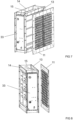
Figure 1 shows an embodiment of the blast damper, -
Figure 2 shows the blast damper shown infigure 1 in a state, where the protective screen has been removed and moved to a distance from the rest of the blast damper, -
Figure 3 shows the blast damper shown infigure 1 in cross section in a state, where the closing blades are in an open position, -
Figure 4 shows the blast damper shown infigure 1 in cross section in a state, where the closing blades are in a closed position, -
Figure 5 shows the blast damper shown infigure 1 in a state, where the protective screen has been removed and moved to a distance from the rest of the blast damper -
Figure 6 shows the blast damper shown infigure 1 in a state, where the protective screen has been removed and moved to a distance from the rest of the blast damper, and where the actuating mechanism is covered with a protective cover, -
Figure 7 shows the blast damper shown infigure 1 in a state, where the protective screen has been removed and moved to a distance from the rest of the blast damper, and where the actuating mechanism is covered with a protective cover, and -
Figure 8 shows the blast damper shown infigure 1 in a state, where the protective screen has been removed and moved to a distance from the rest of the blast damper, and where the actuating mechanism is covered with a protective cover. - Next the
blast damper 1 and some variants and embodiments of theblast damper 1 will be presented in greater detail. - The
blast damper 1 comprises aframe 2 defining aflow channel 3 for air flow through theblast damper 1. - The
flow channel 3 defines anupstream end 9 and adownstream end 10. - The
blast damper 1 comprisesclosing blades 4 pivotally arranged in theflow channel 3. Theclosing blades 4 are preferably, but not necessarily, arranged in parallel in theflow channel 3. - Each
closing blade 4 can be pivoted about a pivot axis (not marked with a reference numeral) between a closed position and an open position. The pivot axes of theclosing blades 4 are preferably, but not necessarily, parallel. - Each
closing blade 4 is pivotally supported at theframe 2 by means of shaft means 5. - The
blast damper 1 comprises anactuating mechanism 20 configured to simultaneously pivot eachclosing blade 4 between the closed position so as to prevent air flow through theblast damper 1 and the open position so as to allow air flow through theblast damper 1. - The
actuating mechanism 20 comprises preferably, but not necessarily, a prestressing arrangement for prestressing theclosing blades 4 into the open position and for triggering theclosing blades 4 to turn into the closed position in response to a pressure increase in theflow channel 3. - The prestressing arrangement can for example function so that the
closing blades 4 are configured to pivot into the closed position in response to a pressure increase in theflow channel 3 sensed by at least one of theclosing blades 4. Theclosing blades 4 are in such case preferably, but not necessarily, configured to pivot into the closed position in response to a pressure increase exceeding a threshold value in theflow channel 3 sensed by at least one of theclosing blades 4. - The prestressing arrangement can for example function so that the
closing blades 4 are configured to pivot into the closed position in response to a pressure increase in theflow channel 3 sensed by a separate pressure sensing device (not illustrated in the figures) that is functionally connected to at least one of the actuating mechanism and at least one of the closing blades. In such case, theclosing blades 4 are preferably, but not necessarily, configured to pivot into the closed position in response to a pressure increase exceeding a threshold value in theflow channel 3 sensed by such separate pressure sensing device. - The
blast damper 1 comprises aprotective screen 11 at theupstream end 9 of theflow channel 3. A purpose of theprotective screen 11 is to prevent solid objects or the like from entering theflow channel 3. - The
protective screen 11 is formed of sheet material and being planar and being provided withflow openings 12. - The sheet material is a metal plate.
- The sheet material has a monolithic structure.
- The
protective screen 11 has a monolithic structure. An example of aprotective screen 11 of monolithic structure is aprotective screen 11 formed of a metal plate by machining it into the final form and dimensions and design. - Because
protective screen 11 is formed of sheet material and being planar and being provided withflow openings 12, theprotective screen 11 of theblast damper 1 is therefore of a simple construction, because it can for example be made of a metal sheet by machining the metal sheet to have the desired design and dimensions. Laser cutting can be used in the manufacturing especially if the sheet material is a metal plate. As theprotective screen 11 is formed of a sheet material and being planar, the extension in the direction of the flow through theflow channel 3 of theblast damper 1 will also be small, because the extension in the direction of the flow through theflow channel 3 of theblast damper 1 is basically the thickness of the sheet material. This makes it possible to use and install theblast damper 1 also in thinner walls compared to what is possible with known blast dampers. - The
frame 2 of theblast damper 1 comprises preferably, but not necessarily, a firstplanar flange 13 at theupstream end 9 of theflow channel 3. - If the
frame 2 of theblast damper 1 comprises a firstplanar flange 13 at theupstream end 9 of theflow channel 3, theframe 2 comprises preferably, but not necessarily, a secondplanar flange 14 at thedownstream end 10 of theflow channel 3 so that the firstplanar flange 13 and the and secondplanar flange 14 are essentially parallel, and theframe 2 comprises preferably, but not necessarily, aweb section 15 between the firstplanar flange 13 and the secondplanar flange 14. - The
frame 2 of theblast damper 1 is preferably, but not necessarily, formed of metal sheet material. - If the
frame 2 of theblast damper 1 comprises a firstplanar flange 13 at theupstream end 9 of theflow channel 3, theprotective screen 11 is preferably, but not necessarily, parallel with the firstplanar flange 13. - If the
frame 2 of theblast damper 1 comprises a firstplanar flange 13 at theupstream end 9 of theflow channel 3, theprotective screen 11 is preferably, but not necessarily, mounted to abut the firstplanar flange 13 of theframe 2. - If the
frame 2 of theblast damper 1 comprises a firstplanar flange 13 at theupstream end 9 of theflow channel 3, theprotective screen 11 has preferably, but not necessarily, aframe part 16 that configured to abut the firstplanar flange 13 of theframe 2 and that is provided with throughholes 17 for fastening means to fasten theprotective screen 11 to the firstplanar flange 13 of theframe 2, so that theflow openings 12 are provided in a central part (not marked with a reference numeral) that is surrounded by theframe part 16. - If the
frame 2 of theblast damper 1 comprises a firstplanar flange 13 at theupstream end 9 of theflow channel 3, theprotective screen 11 has preferably, but not necessarily, essentially the same thickness as the firstplanar flange 13 of theframe 2. - The
flow openings 12 of theprotective screen 11 are preferably, but not necessarily, formed by a grid (not marked with a reference numeral) withlongitudinal grid members 18 andtransversal grid members 19 formed by material of the planar monolithic part. At least some of theflow openings 12 can alternatively be round holes or have another form. The form and the dimensions of the flow openings can be selected for example in accordance with the required strength of theprotective screen 12 or to have a certain look. - The
actuating mechanism 20 comprises preferably, but not necessarily, turning levers 7 so that oneturning lever 7 is fixed to the shaft means 5 of eachclosing blade 4 and acommon operating lever 8 in turnably fixed to eachturning lever 7 such that theclosing blades 4 are configured to simultaneously pivot between the closed position so as to prevent air flow through theblast damper 1, and the open position so as to allow air flow through theblast damper 1. - A
protective cover 33 can be provided to protect theactuating mechanism 20. - The
frame 2 comprises preferably, but not necessarily, afirst profile section 26, asecond profile section 27 that is parallel with thefirst profile section 26, athird profile section 28, and afourth profile section 29 that is parallel with thethird profile section 28 so that thefirst profile section 26 and thesecond profile section 27 extend in parallel with the pivot axes of theclosing blades 4, and so that thefirst profile section 26, thesecond profile section 27, thethird profile section 28, and thefourth profile section 29 together limits theflow channel 3. - Each
closing blade 4 have preferably, but not necessarily, a leadingedge 21 provided with aleading end section 22 that extends perpendicularly to amiddle section 23 of the closing and a trailingedge 24 provided with a trailingend section 25 that extends perpendicularly to themiddle section 23 of theclosing blades 4 so that theclosing blades 4 have an U-shaped cross-section form. Eachclosing blade 4 is preferably, but not necessarily, made of sheet metal. If the frame 2 comprises, a first profile section 26, a second profile section 27 that is parallel with the first profile section 26, a third profile section 28, and a fourth profile section 29 that is parallel with the third profile section 28 so that the first profile section 26 and the second profile section 27 extend in parallel with the pivot axes of the closing blades 4, and so that the first profile section 26, the second profile section 27, the third profile section 28, and the fourth profile section 29 together limits the flow channel 3 and if each closing blade 4 have a leading edge 21 provided with a leading end section 22 that extends perpendicularly to a middle section 23 of the closing and a trailing edge 24 provided with a trailing end section 25 that extends perpendicularly to the middle section 23 of the closing blades 4 so that the closing blades 4 have an U-shaped cross-section form, the closing blades 4 are preferably, but not necessarily, dimensioned so that when each closing blade 4 is in the closed position, the leading end section of the closing blade 4 settles against the middle section of the adjacent closing blade 4 and so that the leading end section of the closing blade 4 closest to the first profile section 26 of the frame 2 settle against the first profile section 26 of the frame 2, and so that the trailing end section of the closing blade 4 closest to the second profile section 27 of the frame 2 settle against the second profile section 27 of the frame 2. - In the
blast damper 1 illustrated in the figures, thefirst profile section 26 of theframe 2 has astep formation 30 and the leading end section of theclosing blade 4 closest to thefirst profile section 26 of theframe 2 settle against the step formation of thefirst profile section 26 of theframe 2. Provision of such leading end section and of such trailing end section makes theclosing blades 4 stiffer and makes theclosing blades 4 to more securely close theflow channel 3 in the closed position. - In the
flow channel 3 can flowcontrollers 31 be provided between twoadjacent closing blades 4, as illustrated in the figures. In the figures, theflow controllers 31 extend between thethird profile section 28 and thefourth profile section 29 essentially parallel to theflow channel 3 and to the flow direction of theblast damper 1 and essentially perpendicularly to thethird profile section 28 of theframe 2 and to thefourth profile section 29 of theframe 2 and essentially in parallel with thefirst profile section 26 of theframe 2 and thesecond profile section 27 of theframe 2. Asupport 32 for theflow controllers 31 can be provided essentially in the middle of theflow channel 3. Thesupport 32 can, as illustrated in the figures, extend between thefirst profile section 26 and thesecond profile section 27 essentially parallel to theflow channel 3 and to the flow direction of theblast damper 1 and essentially perpendicularly to thefirst profile section 26 of theframe 2 and to thesecond profile section 27 of theframe 2 and essentially in parallel with thethird profile section 28 of theframe 2 and with thefourth profile section 29 of theframe 2. Theclosing blades 4 can be dimensioned so, as illustrated in the figures, that when eachclosing blade 4 is in the closed position, the middle section of theclosing blades 4, except for the middle section of theclosing blade 4 closest to thefirst profile section 26 of theframe 2 settle against theflow controllers 31.
Claims (9)
- A blast damper (1) comprisinga frame (2) defining a flow channel (3) for air flow through the blast damper (1), wherein the flow channel (3) defines an upstream end (9) and a downstream end (10),closing blades (4) pivotally arranged in the flow channel (3), wherein each closing blade (4) can be pivoted about a pivot axis between a closed position and an open position and wherein each closing blade (4) is pivotally supported at the frame (2) by means of shaft means (5),an actuating mechanism (20) configured to simultaneously pivot each closing blade (4) between the closed position so as to prevent air flow through the blast damper (1) and the open position so as to allow air flow through the blast damper (1), anda protective screen (11) at the upstream end (9) of the flow channel (3),characterizedby the protective screen (11) being formed of sheet material and being planar and being provided with flow openings (12),by the sheet material being a metal plate.by the sheet material having a monolithic structure. andby the protective screen (11) having a monolithic structure.
- The blast damper (1) according to claim 1, characterized
by the frame (2) comprising a first planar flange (13) at the upstream end (9) of the flow channel (3). - The blast damper (1) according to claim 2, characterizedby the frame (2) comprising a second planar flange (14) at the downstream end (10) of the flow channel (3), wherein the first planar flange (13) and the second planar flange (14) being essentially parallel, andby the frame (2) comprising a web section (15) between the first planar flange (13) and the second planar flange (14).
- The blast damper (1) according to claim 2 or 3, characterized
by the protective screen (11) being parallel with the first planar flange (13). - The blast damper (1) according to any of the claims 2 to 4, characterized
by the protective screen (11) being mounted to abut the first planar flange (13) of the frame (2). - The blast damper (1) according to claim 5, characterizedby the protective screen (11) having a frame part (16) that configured to abut the first planar flange (13) of the frame (2) and that is provided with through holes (17) for fastening means to fasten the protective screen (11) to the first planar flange (13) of the frame (2), andby the flow openings (12) are provided in a central part that is surrounded by the frame part (16).
- The blast damper (1) according to any of the claims 2 to 6, characterized
by the protective screen (11) having the same thickness as the first planar flange (13) of the frame (2). - The blast damper (1) according to any of the claims 1 to 7, characterized
by the flow openings (12) of the protective screen (11) being formed by a grid with longitudinal grid members (18) and transversal grid members (19) formed by material of the planar monolithic part. - The blast damper (1) according to any of the claims 1 to 8, characterized
by an actuating mechanism (20) comprising turning levers (7) so that one turning lever (7) is fixed to the shaft means (5) of each closing blade (4) and a common operating lever (8) in turnably fixed to each turning lever (7) such that the closing blades (4) are configured to simultaneously pivot between the closed position so as to prevent air flow through the blast damper (1), and the open position so as to allow air flow through the blast damper (1).
Applications Claiming Priority (1)
| Application Number | Priority Date | Filing Date | Title |
|---|---|---|---|
| FI20215412A FI20215412A1 (en) | 2021-04-07 | 2021-04-07 | Blast damper |
Publications (3)
| Publication Number | Publication Date |
|---|---|
| EP4071422A1 EP4071422A1 (en) | 2022-10-12 |
| EP4071422B1 true EP4071422B1 (en) | 2025-06-25 |
| EP4071422C0 EP4071422C0 (en) | 2025-06-25 |
Family
ID=81324914
Family Applications (1)
| Application Number | Title | Priority Date | Filing Date |
|---|---|---|---|
| EP22166460.0A Active EP4071422B1 (en) | 2021-04-07 | 2022-04-04 | Blast damper |
Country Status (4)
| Country | Link |
|---|---|
| EP (1) | EP4071422B1 (en) |
| CN (1) | CN115199798A (en) |
| FI (1) | FI20215412A1 (en) |
| PL (1) | PL4071422T3 (en) |
Family Cites Families (7)
| Publication number | Priority date | Publication date | Assignee | Title |
|---|---|---|---|---|
| US4208010A (en) * | 1978-07-14 | 1980-06-17 | Beam Dennis A Jr | Ventilator assembly |
| US4210279A (en) * | 1979-03-01 | 1980-07-01 | Mcswain Edward D | Temperature-responsive automatic ventilator |
| US6129113A (en) * | 1998-10-16 | 2000-10-10 | Tomkins Industries, Inc. | Air flow measurement station with orthogonally mounted damper |
| FI126224B (en) | 2015-03-06 | 2016-08-31 | Temet Oy | Pressure valve and procedure for regulating pressure valve |
| CN105546129B (en) * | 2016-01-28 | 2018-08-14 | 江苏爵格工业设备有限公司 | A kind of rain-proof shock wave resistance valve |
| CN110715086B (en) * | 2019-09-26 | 2025-08-08 | 江苏爵格工业集团有限公司 | A bidirectional anti-shock wave valve |
| CN212360951U (en) * | 2020-06-05 | 2021-01-15 | 绍兴市上虞江南风机有限公司 | Anticorrosion smoke exhaust valve |
-
2021
- 2021-04-07 FI FI20215412A patent/FI20215412A1/en not_active Application Discontinuation
-
2022
- 2022-04-04 PL PL22166460.0T patent/PL4071422T3/en unknown
- 2022-04-04 EP EP22166460.0A patent/EP4071422B1/en active Active
- 2022-04-07 CN CN202210372902.2A patent/CN115199798A/en active Pending
Also Published As
| Publication number | Publication date |
|---|---|
| CN115199798A (en) | 2022-10-18 |
| FI20215412A1 (en) | 2022-10-08 |
| EP4071422A1 (en) | 2022-10-12 |
| EP4071422C0 (en) | 2025-06-25 |
| PL4071422T3 (en) | 2026-03-09 |
Similar Documents
| Publication | Publication Date | Title |
|---|---|---|
| CA2710739C (en) | Back draft damper | |
| EP3265706B1 (en) | A pressure valve and method of adjusting a pressure valve | |
| EP2297527B1 (en) | Pressure valve | |
| US9845893B2 (en) | Exhaust gate | |
| US20100150544A1 (en) | Iris damper | |
| US11458806B2 (en) | HVAC inlet with ram air and partial recirculation function | |
| EP4071422A1 (en) | Blast damper | |
| EP1040291A1 (en) | Noise attenuating device for butterfly valves | |
| EP3318786B1 (en) | Check valve | |
| US5766072A (en) | Ventilation arrangement, including filter constructed as sound dampener, flow damper and for filtering purposes | |
| EP2297526B1 (en) | Pressure valve | |
| EP4071421B1 (en) | Blast damper | |
| EP4071423B1 (en) | Blast damper | |
| NL192890C (en) | Condensate drain. | |
| EP1878893B1 (en) | Exhaust gas turbo charger assembly | |
| FI13559Y1 (en) | Blast damper | |
| US20100236650A1 (en) | Butterfly valve combined with check valve | |
| GB2611178A (en) | Exhaust silencer | |
| EP4095421A1 (en) | Damper assembly | |
| US20130306746A1 (en) | Retrofit Flap Damper Assembly System for Cone Type Damper Variable Air Volume Boxes | |
| EP4083478B1 (en) | Flapper check valve | |
| EP1303716B1 (en) | Damper in an air conditioning system comprising a casing part with a turnable blade | |
| DE20304825U1 (en) | Tension Controller | |
| CZ20032649A3 (en) | Flame trap for gas-pipes | |
| NZ513123A (en) | An improved blade for a vent grille |
Legal Events
| Date | Code | Title | Description |
|---|---|---|---|
| PUAI | Public reference made under article 153(3) epc to a published international application that has entered the european phase |
Free format text: ORIGINAL CODE: 0009012 |
|
| STAA | Information on the status of an ep patent application or granted ep patent |
Free format text: STATUS: REQUEST FOR EXAMINATION WAS MADE |
|
| 17P | Request for examination filed |
Effective date: 20220404 |
|
| AK | Designated contracting states |
Kind code of ref document: A1 Designated state(s): AL AT BE BG CH CY CZ DE DK EE ES FI FR GB GR HR HU IE IS IT LI LT LU LV MC MK MT NL NO PL PT RO RS SE SI SK SM TR |
|
| GRAP | Despatch of communication of intention to grant a patent |
Free format text: ORIGINAL CODE: EPIDOSNIGR1 |
|
| STAA | Information on the status of an ep patent application or granted ep patent |
Free format text: STATUS: GRANT OF PATENT IS INTENDED |
|
| INTG | Intention to grant announced |
Effective date: 20250224 |
|
| GRAS | Grant fee paid |
Free format text: ORIGINAL CODE: EPIDOSNIGR3 |
|
| GRAA | (expected) grant |
Free format text: ORIGINAL CODE: 0009210 |
|
| STAA | Information on the status of an ep patent application or granted ep patent |
Free format text: STATUS: THE PATENT HAS BEEN GRANTED |
|
| AK | Designated contracting states |
Kind code of ref document: B1 Designated state(s): AL AT BE BG CH CY CZ DE DK EE ES FI FR GB GR HR HU IE IS IT LI LT LU LV MC MK MT NL NO PL PT RO RS SE SI SK SM TR |
|
| REG | Reference to a national code |
Ref country code: GB Ref legal event code: FG4D |
|
| REG | Reference to a national code |
Ref country code: CH Ref legal event code: EP |
|
| REG | Reference to a national code |
Ref country code: CH Ref legal event code: EP |
|
| REG | Reference to a national code |
Ref country code: IE Ref legal event code: FG4D |
|
| REG | Reference to a national code |
Ref country code: DE Ref legal event code: R096 Ref document number: 602022016299 Country of ref document: DE |
|
| U01 | Request for unitary effect filed |
Effective date: 20250721 |
|
| U07 | Unitary effect registered |
Designated state(s): AT BE BG DE DK EE FI FR IT LT LU LV MT NL PT RO SE SI Effective date: 20250728 |
|
| PG25 | Lapsed in a contracting state [announced via postgrant information from national office to epo] |
Ref country code: NO Free format text: LAPSE BECAUSE OF FAILURE TO SUBMIT A TRANSLATION OF THE DESCRIPTION OR TO PAY THE FEE WITHIN THE PRESCRIBED TIME-LIMIT Effective date: 20250925 Ref country code: GR Free format text: LAPSE BECAUSE OF FAILURE TO SUBMIT A TRANSLATION OF THE DESCRIPTION OR TO PAY THE FEE WITHIN THE PRESCRIBED TIME-LIMIT Effective date: 20250926 |
|
| PG25 | Lapsed in a contracting state [announced via postgrant information from national office to epo] |
Ref country code: HR Free format text: LAPSE BECAUSE OF FAILURE TO SUBMIT A TRANSLATION OF THE DESCRIPTION OR TO PAY THE FEE WITHIN THE PRESCRIBED TIME-LIMIT Effective date: 20250625 |
|
| PG25 | Lapsed in a contracting state [announced via postgrant information from national office to epo] |
Ref country code: RS Free format text: LAPSE BECAUSE OF FAILURE TO SUBMIT A TRANSLATION OF THE DESCRIPTION OR TO PAY THE FEE WITHIN THE PRESCRIBED TIME-LIMIT Effective date: 20250925 |
|
| PG25 | Lapsed in a contracting state [announced via postgrant information from national office to epo] |
Ref country code: IS Free format text: LAPSE BECAUSE OF FAILURE TO SUBMIT A TRANSLATION OF THE DESCRIPTION OR TO PAY THE FEE WITHIN THE PRESCRIBED TIME-LIMIT Effective date: 20251025 |
|
| PG25 | Lapsed in a contracting state [announced via postgrant information from national office to epo] |
Ref country code: SM Free format text: LAPSE BECAUSE OF FAILURE TO SUBMIT A TRANSLATION OF THE DESCRIPTION OR TO PAY THE FEE WITHIN THE PRESCRIBED TIME-LIMIT Effective date: 20250625 |
|
| PG25 | Lapsed in a contracting state [announced via postgrant information from national office to epo] |
Ref country code: CZ Free format text: LAPSE BECAUSE OF FAILURE TO SUBMIT A TRANSLATION OF THE DESCRIPTION OR TO PAY THE FEE WITHIN THE PRESCRIBED TIME-LIMIT Effective date: 20250625 |
|
| PG25 | Lapsed in a contracting state [announced via postgrant information from national office to epo] |
Ref country code: SK Free format text: LAPSE BECAUSE OF FAILURE TO SUBMIT A TRANSLATION OF THE DESCRIPTION OR TO PAY THE FEE WITHIN THE PRESCRIBED TIME-LIMIT Effective date: 20250625 |
|
| PG25 | Lapsed in a contracting state [announced via postgrant information from national office to epo] |
Ref country code: ES Free format text: LAPSE BECAUSE OF FAILURE TO SUBMIT A TRANSLATION OF THE DESCRIPTION OR TO PAY THE FEE WITHIN THE PRESCRIBED TIME-LIMIT Effective date: 20250625 |
|
| PGFP | Annual fee paid to national office [announced via postgrant information from national office to epo] |
Ref country code: GB Payment date: 20260311 Year of fee payment: 5 |
|
| U20 | Renewal fee for the european patent with unitary effect paid |
Year of fee payment: 5 Effective date: 20260306 |
|
| PLBE | No opposition filed within time limit |
Free format text: ORIGINAL CODE: 0009261 |
|
| STAA | Information on the status of an ep patent application or granted ep patent |
Free format text: STATUS: NO OPPOSITION FILED WITHIN TIME LIMIT |
|
| REG | Reference to a national code |
Ref country code: CH Ref legal event code: L10 Free format text: ST27 STATUS EVENT CODE: U-0-0-L10-L00 (AS PROVIDED BY THE NATIONAL OFFICE) Effective date: 20260507 |
|
| 26N | No opposition filed |
Effective date: 20260326 |