EP4071392B1 - Offshore pipelaying system using friction stir welding - Google Patents
Offshore pipelaying system using friction stir welding Download PDFInfo
- Publication number
- EP4071392B1 EP4071392B1 EP22166844.5A EP22166844A EP4071392B1 EP 4071392 B1 EP4071392 B1 EP 4071392B1 EP 22166844 A EP22166844 A EP 22166844A EP 4071392 B1 EP4071392 B1 EP 4071392B1
- Authority
- EP
- European Patent Office
- Prior art keywords
- fsw
- machines
- pipes
- vessel
- conveyor
- Prior art date
- Legal status (The legal status is an assumption and is not a legal conclusion. Google has not performed a legal analysis and makes no representation as to the accuracy of the status listed.)
- Active
Links
Images



Classifications
-
- F—MECHANICAL ENGINEERING; LIGHTING; HEATING; WEAPONS; BLASTING
- F16—ENGINEERING ELEMENTS AND UNITS; GENERAL MEASURES FOR PRODUCING AND MAINTAINING EFFECTIVE FUNCTIONING OF MACHINES OR INSTALLATIONS; THERMAL INSULATION IN GENERAL
- F16L—PIPES; JOINTS OR FITTINGS FOR PIPES; SUPPORTS FOR PIPES, CABLES OR PROTECTIVE TUBING; MEANS FOR THERMAL INSULATION IN GENERAL
- F16L1/00—Laying or reclaiming pipes; Repairing or joining pipes on or under water
- F16L1/12—Laying or reclaiming pipes on or under water
- F16L1/16—Laying or reclaiming pipes on or under water on the bottom
- F16L1/18—Laying or reclaiming pipes on or under water on the bottom the pipes being S- or J-shaped and under tension during laying
-
- B—PERFORMING OPERATIONS; TRANSPORTING
- B23—MACHINE TOOLS; METAL-WORKING NOT OTHERWISE PROVIDED FOR
- B23K—SOLDERING OR UNSOLDERING; WELDING; CLADDING OR PLATING BY SOLDERING OR WELDING; CUTTING BY APPLYING HEAT LOCALLY, e.g. FLAME CUTTING; WORKING BY LASER BEAM
- B23K20/00—Non-electric welding by applying impact or other pressure, with or without the application of heat, e.g. cladding or plating
- B23K20/12—Non-electric welding by applying impact or other pressure, with or without the application of heat, e.g. cladding or plating the heat being generated by friction; Friction welding
- B23K20/122—Non-electric welding by applying impact or other pressure, with or without the application of heat, e.g. cladding or plating the heat being generated by friction; Friction welding using a non-consumable tool, e.g. friction stir welding
- B23K20/1245—Non-electric welding by applying impact or other pressure, with or without the application of heat, e.g. cladding or plating the heat being generated by friction; Friction welding using a non-consumable tool, e.g. friction stir welding characterised by the apparatus
-
- F—MECHANICAL ENGINEERING; LIGHTING; HEATING; WEAPONS; BLASTING
- F16—ENGINEERING ELEMENTS AND UNITS; GENERAL MEASURES FOR PRODUCING AND MAINTAINING EFFECTIVE FUNCTIONING OF MACHINES OR INSTALLATIONS; THERMAL INSULATION IN GENERAL
- F16L—PIPES; JOINTS OR FITTINGS FOR PIPES; SUPPORTS FOR PIPES, CABLES OR PROTECTIVE TUBING; MEANS FOR THERMAL INSULATION IN GENERAL
- F16L13/00—Non-disconnectable pipe joints, e.g. soldered, adhesive, or caulked joints
- F16L13/02—Welded joints
-
- B—PERFORMING OPERATIONS; TRANSPORTING
- B23—MACHINE TOOLS; METAL-WORKING NOT OTHERWISE PROVIDED FOR
- B23K—SOLDERING OR UNSOLDERING; WELDING; CLADDING OR PLATING BY SOLDERING OR WELDING; CUTTING BY APPLYING HEAT LOCALLY, e.g. FLAME CUTTING; WORKING BY LASER BEAM
- B23K2101/00—Articles made by soldering, welding or cutting
- B23K2101/04—Tubular or hollow articles
- B23K2101/10—Pipe-lines
Definitions
- Offshore pipelines are typically deployed or "laid” using either S-lay or J-lay vessels and techniques.
- the names for these vessels/techniques are given based on the shape that the deployed pipeline makes as it extends from the vessel toward the seafloor.
- S-lay operation the pipeline is generally horizontal on the vessel deck, where additional lengths of pipe are attached to the pipeline, to extend the pipeline.
- the pipeline curves from horizontal to near vertical, and then back to horizontal at the seafloor.
- J-lay operation the pipeline is generally deployed in a vertical or near vertical orientation from the vessel toward the seafloor, where it curves toward horizontal.
- the vessel generally moves as the pipe is deployed, thereby laying the pipeline along the sea floor.
- additional lengths of pipe are connected to the end of the pipeline, typically by arc welding.
- the process generally proceeds by one or more lengths of pipe being received into a conveyor, often referred to as a firing line, where it is welded to the end of the pipeline that is currently being deployed.
- a conveyor often referred to as a firing line
- the new or "add-on" pipe is welded in a generally horizontal orientation to the pipeline
- several add-on pipe segments may be welded together into an assembly and then the assembly is brought to (or near to) a vertical orientation and then welded onto the end of the pipeline.
- EP0271184A1 discloses a convertible barge having self-contained modules positioned thereon containing pipeline processing equipment, the modules being removably attached to the deck of the barge.
- US2009/134203A1 discloses positioning a friction stir welder (FSW) proximate to the seam between tubular sections and guiding the FSW along the seam forming a weld joint.
- FSW friction stir welder
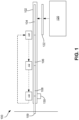
- FIG. 1 illustrates a schematic view of a pipeline assembly system 100, according to an embodiment.
- the pipeline assembly system 100 may be at least partially provided on the deck of a marine vessel (e.g., a ship) that may be underway or docked.
- the vessel may be configured to lay pipe either in an S-lay or J-lay operation, as will be described in greater detail below.
- the system 100 may generally include a conveyor 102, which may be a relatively long and narrow structure configured to receive and permit pipes 104, 106, and 108 to smoothly slide along. It will be appreciated that conveyors of various types and other mechanisms to move the pipe may be employed for the conveyor 102, and, moreover, that the conveyor 102 may be configured to receive any number of pipes, with the three pipes 104-108 shown being merely an example.
- the conveyor 102 may be generally horizontally disposed or generally vertically disposed on the deck of the vessel. A generally horizontal disposition may be employed for S-lay operations, and generally vertical disposition (e.g., on a vertical ramp structure) may be employed for J-lay operations. It will be appreciated that either such generally horizontal or generally vertical configurations are within the scope of the present disclosure.
- the pipes 104-108 may be configured to be coupled together, end-to-end, and to a previously-deployed pipeline 109 that may extend from the vessel down toward the seafloor.
- the pipes 104-108 shown may actually each be two or more pipe segments that were previously joined together, e.g., as "doubles" or “triples” of two or three pipes, respectively.
- the pre-connecting of two or more pipes, e.g., on-shore or while the vessel is travelling to a pipelaying position, may reduce the number of connections to be made during pipelaying operations.
- the system 100 may also include one or more friction stir welding (FSW) machines.
- FSW friction stir welding
- the FSW machines 110-114 may each include a tool that has a cylindrical body with a shoulder and protruding pin. The tool is rotated at high velocity and plunged into the interface between the two pipes until the shoulder and pipe material come into contact. The tool dwells in place and generates frictional heating that, when combined with the rotation of the tool, plasticizes the material. Once sufficient plasticization is achieved, the tool traverses a prescribed path (e.g., the circumferential interface between the two adjacent pipes) to complete the joint.
- a prescribed path e.g., the circumferential interface between the two adjacent pipes
- the FSW machines 110-114 may move in a direction along the axis of the conveyor 102 and the pipes 104-108, with respect to the vessel (e.g., generally vertically or horizontally, depending on the type of pipelaying operation/vessel). Further, the FSW machines 110-114 may move along a circuit (e.g., along a track), which runs along the axis of the conveyor 102 until reaching some end point near to where the pipeline 109 is deployed from the vessel into the body of water. The end point may be common to all of the FSW machines 110-114.
- a circuit e.g., along a track
- the track (whether structural or virtual) may route the individual FSW machines 110-114 back to a common starting point that is offset from the end point along the conveyor 102, e.g., where FSW machine 114 is shown in Figure 1 . Accordingly, the FSW machines 110-114 may each traverse the same circuit/track.
- the system 100 may further include a pipe hopper 120.
- the hopper 120 may be a rack configured to store multiple pipes 122, which may be loaded onto the conveyor 102.
- the hopper 120 may be positioned on the marine vessel or on a separate "auxiliary" vessel that is temporarily held alongside the marine vessel.
- the system 100 may also include an inspection tool 130.
- the inspection tool 130 may be positioned at an end of the conveyor 102, proximal to where the pipeline 109 extends from the vessel. In other embodiments, multiple inspection tools 130 may be provided, e.g., at intervals along the length of the conveyor 102. In still other embodiments, the inspection tool 130 may be integrated into the FSW machines 110-114, e.g., mounted to the FSW head, mounted to a separate appendage, and/or mounted on a separate head capable of traversing the completed joint.
- the inspection tool 130 may perform non-destructive examination (NDE) of the connections formed by the FSW machines 110-114.
- NDE non-destructive examination
- the inspection tool 130 may include ultrasonic transducers, magnetic coils, etc. NDE stations may also be integrated within the fabrication process owing to the lower joining temperatures afforded by FSW. Because of these lower temperatures, the completed connections (and/or other sections of the pipes 104-108) may be inspected almost immediately upon completion as opposed to conventional fabrication processes which require substantial cooling time to lapse before inspection can occur.
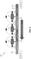
- FIG 2 illustrates a schematic view of another embodiment of the system 100.
- the travel distance of the FSW machines 110-114 may be reduced as compared to the travel distance of the FSW machines 110-114 in Figure 1 .
- the FSW machines 110-114 may each move between respective starting positions A and ending positions B, with the ending position of one FSW machine (e.g., FSW machine 112) being adjacent and closely proximal to the starting position A of the next FSW machine (e.g., FSW machine 110).
- the FSW machines 110-114 may thus form the connections between adjacent pipes 104-108 and the pipeline 109 as the FSW machines 110-114 travel between their respective starting and ending points A, B.
- the FSW machines 110-114 may travel back to their respective starting points A, so as to begin preparing more connections.
- the position of the connection being made, between points A and B for the respective paths of the FSW machines 110, 112, 114 parallel to the pipeline 109 may be variable, e.g., independently.
- the FSW machines 110, 112, 114 may be configured in some embodiments to move along with the pipeline 109 as it is deployed (as will be discussed below), and also to accommodate pipe joints of differing lengths.
- the system 100 may permit the vessel 300 to move while the connections are being made. That is, the FSW machines 110-114 (FSW machine 110 is shown for illustrative purposes in Figure 3 ), may move relative to the vessel in an equal (or substantially equal) speed and in an opposite direction to the vessel 300 (e.g., as discussed above with respect to either Figure 1 or Figure 2 ). Accordingly, the FSW machines 110-114, while forming the connections, may maintain the same position with respect to the pipeline 109 (e.g., aligned with a connection between two pipes 104-108), while the vessel 300 moves.
- the pipeline 109 e.g., aligned with a connection between two pipes 104-108
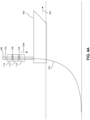
- FIG. 4A illustrates a side, schematic view of a vessel 400 deploying the pipeline 109 in a J-lay configuration, according to an embodiment.
- the vessel 400 may also include at least a portion of either or both of the embodiments of the system 100 discussed above, and may include a propulsion system configured to move the vessel 400 in a direction 404 along the surface of the body of water.
- the vessel 400 may also include a vertically-extending conveyor 406 on which the FSW machines 110-114 may move, e.g., in direction 408.
- the FSW machines 110-114 may move in the direction 408, while the FSW machines 110-114 are welding, at the same rate as the vessel 400 moves in the direction 404, thereby maintaining position at the connection between two pipes.
- the FSW machines 110-114 may remain in a constant position relative to the pipes 104-108 that they are connecting together and/or to the pipeline 109, permitting the machines 110-114 to finish the connection despite the movement of the vessel playing out the pipes/pipeline.
- the method 500 may include coordinating the speeds of the FSW machines 110-114 and the vessel 300/400 in order to move the FSW machines 110-114 and the vessel 300, 400.
- the FSW machines 110-114 may not move.
- the local starting point may be adjustable, e.g., depending on a relative location of an end of the pipes 104-108, which may be detected using any suitable device (e.g., optically, using a mechanical gauge, etc.).
- the FSW machines 110-114 may thus be configured to move independently of one another, and relative to one another, in order to find a specific, local starting point where the ends of adjacent pipes 104-108 meet.
- the FSW machines 110-114 may move along the conveyor 102 and may perform the welding process at a speed that at least partially depends on the speed of the vessel 400.
- the speed of the vessel 400 may also be manipulated to accommodate the speed constraints of the FSW machines 110-114 (both in terms of their ability to move along the conveyor 102 and to perform the welding process).
- the method 500 may also include preheating the pipes 104-108, e.g., immediately ahead of the individual FSW machines 110-114. This may reduce wear on the tools of the FSW machines 110-114 and increase joining speed. Preheating may be applied by, for example, induction, flame, or mechanical heating. In at least some embodiments, the pipes 104-108 may be predrilled with a plunge hole at a joint weld start location, which may reduce joining time and wear on the tool.
Landscapes
- Engineering & Computer Science (AREA)
- General Engineering & Computer Science (AREA)
- Mechanical Engineering (AREA)
- Butt Welding And Welding Of Specific Article (AREA)
- Arc Welding In General (AREA)
- Pressure Welding/Diffusion-Bonding (AREA)
- Earth Drilling (AREA)
Description
- This application claims priority to
U.S. Provisional Patent Application having Serial No. 63/171733 - Offshore pipelines are typically deployed or "laid" using either S-lay or J-lay vessels and techniques. The names for these vessels/techniques are given based on the shape that the deployed pipeline makes as it extends from the vessel toward the seafloor. In an S-lay operation, the pipeline is generally horizontal on the vessel deck, where additional lengths of pipe are attached to the pipeline, to extend the pipeline. The pipeline curves from horizontal to near vertical, and then back to horizontal at the seafloor. In J-lay operation, the pipeline is generally deployed in a vertical or near vertical orientation from the vessel toward the seafloor, where it curves toward horizontal. The vessel generally moves as the pipe is deployed, thereby laying the pipeline along the sea floor.
- In both such operations, additional lengths of pipe are connected to the end of the pipeline, typically by arc welding. The process generally proceeds by one or more lengths of pipe being received into a conveyor, often referred to as a firing line, where it is welded to the end of the pipeline that is currently being deployed. In the S-lay configuration, the new or "add-on" pipe is welded in a generally horizontal orientation to the pipeline, and in a J-lay configuration, several add-on pipe segments may be welded together into an assembly and then the assembly is brought to (or near to) a vertical orientation and then welded onto the end of the pipeline.
- Arc welding is successfully employed in the field to join the lengths of pipe to form the pipelines. However, the pipelaying vessel is usually stopped while connections of add-on pipes are made. Once the welded connection is complete, the vessel then moves by the distance of the added pipe(s), and then one or more additional pipes are loaded and connected, and the process repeats. This stop-and-start, incremental progression is time-consuming and calls for vessel operators to constantly start and stop the vessel propulsion system. Moreover, there are other challenges presented to arc welding the pipes together. For example, some metals are difficult to weld, and may be considered un-weldable for practical purposes. Corrosion resistant pipes are sometimes made of such metals. Further, arc welding heats the pipes, or at least portions thereof, to high temperatures, which can affect the metallurgical properties of the pipes and, further, the pipes may need to be cooled before inspection of the welds, further slowing the pipelaying process.
-
EP0271184A1 discloses a convertible barge having self-contained modules positioned thereon containing pipeline processing equipment, the modules being removably attached to the deck of the barge.US2009/134203A1 discloses positioning a friction stir welder (FSW) proximate to the seam between tubular sections and guiding the FSW along the seam forming a weld joint. - The present invention is defined by the independent claims, to which reference should now be made. Advantageous embodiments are set out in the dependent claims.
- The foregoing summary is intended merely to introduce a subset of the features more fully described of the following detailed description. Accordingly, this summary should not be considered limiting.
- The accompanying drawing, which is incorporated in and constitutes a part of this specification, illustrates an embodiment of the present teachings and together with the description, serves to explain the principles of the present teachings. In the figures:
-
Figure 1 illustrates a schematic view of a pipeline assembly system, according to an embodiment. -
Figure 2 illustrates a schematic view of another embodiment of the pipeline assembly system, not forming part of the invention. -
Figure 3 illustrates a schematic view of a S-lay pipelaying vessel, according to an embodiment. -
Figure 4A illustrates a schematic view of a J-lay pipelaying vessel, according to an embodiment. -
Figure 4B illustrates a schematic view of another embodiment of a J-lay pipelaying vessel. -
Figure 5 illustrates a flowchart of a method for pipelaying, according to an embodiment. - It should be noted that some details of the figure have been simplified and are drawn to facilitate understanding of the embodiments rather than to maintain strict structural accuracy, detail, and scale.
- Reference will now be made in detail to embodiments of the present teachings, examples of which are illustrated in the accompanying drawing. In the drawings, like reference numerals have been used throughout to designate identical elements, where convenient. The following description is merely a representative example of such teachings.
-
Figure 1 illustrates a schematic view of apipeline assembly system 100, according to an embodiment. Thepipeline assembly system 100 may be at least partially provided on the deck of a marine vessel (e.g., a ship) that may be underway or docked. The vessel may be configured to lay pipe either in an S-lay or J-lay operation, as will be described in greater detail below. - The
system 100 may generally include aconveyor 102, which may be a relatively long and narrow structure configured to receive and permitpipes conveyor 102, and, moreover, that theconveyor 102 may be configured to receive any number of pipes, with the three pipes 104-108 shown being merely an example. Theconveyor 102 may be generally horizontally disposed or generally vertically disposed on the deck of the vessel. A generally horizontal disposition may be employed for S-lay operations, and generally vertical disposition (e.g., on a vertical ramp structure) may be employed for J-lay operations. It will be appreciated that either such generally horizontal or generally vertical configurations are within the scope of the present disclosure. - The pipes 104-108 may be configured to be coupled together, end-to-end, and to a previously-deployed
pipeline 109 that may extend from the vessel down toward the seafloor. In some embodiments, the pipes 104-108 shown may actually each be two or more pipe segments that were previously joined together, e.g., as "doubles" or "triples" of two or three pipes, respectively. The pre-connecting of two or more pipes, e.g., on-shore or while the vessel is travelling to a pipelaying position, may reduce the number of connections to be made during pipelaying operations. - The
system 100 may also include one or more friction stir welding (FSW) machines. In this example, there are three shown, as indicated byreference numbers - As shown in
Figure 1 , in addition to orbiting the pipes 104-108, the FSW machines 110-114 may move in a direction along the axis of theconveyor 102 and the pipes 104-108, with respect to the vessel (e.g., generally vertically or horizontally, depending on the type of pipelaying operation/vessel). Further, the FSW machines 110-114 may move along a circuit (e.g., along a track), which runs along the axis of theconveyor 102 until reaching some end point near to where thepipeline 109 is deployed from the vessel into the body of water. The end point may be common to all of the FSW machines 110-114. At that point, the track (whether structural or virtual) may route the individual FSW machines 110-114 back to a common starting point that is offset from the end point along theconveyor 102, e.g., whereFSW machine 114 is shown inFigure 1 . Accordingly, the FSW machines 110-114 may each traverse the same circuit/track. - The
system 100 may further include apipe hopper 120. Thehopper 120 may be a rack configured to storemultiple pipes 122, which may be loaded onto theconveyor 102. In some embodiments, thehopper 120 may be positioned on the marine vessel or on a separate "auxiliary" vessel that is temporarily held alongside the marine vessel. - The
system 100 may also include aninspection tool 130. Theinspection tool 130 may be positioned at an end of theconveyor 102, proximal to where thepipeline 109 extends from the vessel. In other embodiments,multiple inspection tools 130 may be provided, e.g., at intervals along the length of theconveyor 102. In still other embodiments, theinspection tool 130 may be integrated into the FSW machines 110-114, e.g., mounted to the FSW head, mounted to a separate appendage, and/or mounted on a separate head capable of traversing the completed joint. - The
inspection tool 130 may perform non-destructive examination (NDE) of the connections formed by the FSW machines 110-114. For example, theinspection tool 130 may include ultrasonic transducers, magnetic coils, etc. NDE stations may also be integrated within the fabrication process owing to the lower joining temperatures afforded by FSW. Because of these lower temperatures, the completed connections (and/or other sections of the pipes 104-108) may be inspected almost immediately upon completion as opposed to conventional fabrication processes which require substantial cooling time to lapse before inspection can occur. - In at least some embodiments, the
system 100 may include one or more devices for detecting a position of the end of a given pipe, e.g.,pipe 106. For example, an optical sensor, an electronic sensor, a mechanical gauge, or the like could be used to provide input as to a location of the end of a givenpipe 106 on theconveyor 102. Detecting the end of thepipe 106 may facilitate rapidly positioning and aligning thepipe 106 relative to an adjacent pipe (e.g.,pipe -
Figure 2 illustrates a schematic view of another embodiment of thesystem 100. In this embodiment, the travel distance of the FSW machines 110-114 may be reduced as compared to the travel distance of the FSW machines 110-114 inFigure 1 . In particular, the FSW machines 110-114 may each move between respective starting positions A and ending positions B, with the ending position of one FSW machine (e.g., FSW machine 112) being adjacent and closely proximal to the starting position A of the next FSW machine (e.g., FSW machine 110). The FSW machines 110-114 may thus form the connections between adjacent pipes 104-108 and thepipeline 109 as the FSW machines 110-114 travel between their respective starting and ending points A, B. Upon reaching the end points B, which may occur simultaneously for the FSW machines 110-114, the FSW machines 110-114 may travel back to their respective starting points A, so as to begin preparing more connections. In at least some embodiments, the position of the connection being made, between points A and B for the respective paths of theFSW machines pipeline 109 may be variable, e.g., independently. Accordingly, theFSW machines pipeline 109 as it is deployed (as will be discussed below), and also to accommodate pipe joints of differing lengths. -
Figure 3 illustrates a side, schematic view of avessel 300 deploying thepipeline 109 in an S-lay configuration, according to an embodiment. Thevessel 300 may include at least a portion of either or both of the embodiments of thesystem 100 discussed above. Thevessel 300 may include a propulsion system, which may be configured to move thevessel 300 along the surface of the body of water, e.g., in thedirection 302. As thevessel 300 moves, thepipeline 109 is played out from thevessel 300. - In some embodiments, the
system 100 may permit thevessel 300 to move while the connections are being made. That is, the FSW machines 110-114 (FSW machine 110 is shown for illustrative purposes inFigure 3 ), may move relative to the vessel in an equal (or substantially equal) speed and in an opposite direction to the vessel 300 (e.g., as discussed above with respect to eitherFigure 1 orFigure 2 ). Accordingly, the FSW machines 110-114, while forming the connections, may maintain the same position with respect to the pipeline 109 (e.g., aligned with a connection between two pipes 104-108), while thevessel 300 moves. Stated otherwise, in this generally horizontal-movement (S-lay) embodiment, the FSW machines 110-114 may remain in a constant position when viewed from a stationary reference point (e.g., viewed from a reference point on the seafloor). In at least some embodiments, a controller may be provided to coordinate the speed at which the FSW machines 110-114 move and the speed at which thevessel 300 moves. For example, the controller may adjust the speed of either in order to match, or substantially match the speeds thereof, such that the FSW machines 110-114 move at substantially the same speed as thevessel 300. In other embodiments, however, the FSW machines 110-114 may be a direct swap for conventional arc welding machines, and may thus be stationary with respect to thevessel 300. In this embodiment vessel movement is incremental and each incremental move occurs after each weld is completed. -
Figure 4A illustrates a side, schematic view of avessel 400 deploying thepipeline 109 in a J-lay configuration, according to an embodiment. Thevessel 400 may also include at least a portion of either or both of the embodiments of thesystem 100 discussed above, and may include a propulsion system configured to move thevessel 400 in adirection 404 along the surface of the body of water. Thevessel 400 may also include a vertically-extendingconveyor 406 on which the FSW machines 110-114 may move, e.g., indirection 408. In an embodiment, the FSW machines 110-114 may move in thedirection 408, while the FSW machines 110-114 are welding, at the same rate as thevessel 400 moves in thedirection 404, thereby maintaining position at the connection between two pipes. Accordingly, thesystem 100 may permit continuous movement of thevessel 400 while laying pipe. In at least some embodiments, a controller may be provided to coordinate the speed at which the FSW machines 110-114 move and the speed at which thevessel 400 moves, as described above, so that the FSW machines 110-114 move at substantially the same speed as thevessel 400. In at least one embodiment, the vessel may also be configured to alter its speed (e.g., relatively small adjustments) to account for variations in conveying pipe. Further, the controller may be provided with vessel speed as an input, and may adjust one or more parameters of the FSW machines 110-114 welding processes to increase welding speed or decreasing welding speed, depending on the speed of the vessel. -
Figure 4B illustrates a side, schematic view of avessel 400 deploying thepipeline 109 in a J-lay configuration, according to an embodiment. Thevessel 400 may also include at least a portion of either or both of the embodiments of thesystem 100 discussed above for preassembling individual segments of pipe in a generally horizontal orientation into an assembly where the assembly is then transferred into the vertically extending conveyor where the assembly is joined to thepipeline 109 atFSW machine 110. The vessel may include a propulsion system configured to move thevessel 400 in adirection 404 along the surface of the body of water. In an embodiment, theFSW machine 110 may move in thedirection 408 at the same rate as thevessel 400 moves in thedirection 404, thereby maintaining position at the connection between two pipes. Accordingly, thesystem 100 may permit continuous movement of thevessel 400 while laying pipe. In at least some embodiments, a controller may be provided to coordinate the speed at which theFSW machine 110 moves and the speed at which thevessel 400 moves, as described above, so that theFSW machine 110 moves at substantially the same speed as thevessel 400. In other embodiments, however, the FSW machines 110-114 may thus be stationary with respect to thevessel 400. In this embodiment vessel movement is incremental and each incremental move occurs after each weld is completed. -
Figure 5 illustrates a flowchart of amethod 500 for pipelaying, according to an embodiment. Themethod 500 may be executed using one or more embodiments of thesystem 100 discussed above, but at least some embodiments of themethod 500 may employ other systems, and thus themethod 500 should not be considered limited to any particular structure, unless otherwise stated herein. Moreover, the steps of themethod 500 may be performed in the order presented below, or in any other order. Some steps of themethod 500 may be combined, partitioned into two or more steps, performed in parallel, or the like, without departing from the scope of the appended claims. - The
method 500 may include positioning one or more pipes (or "pipe segments") 104-108 on aconveyor 102 of a vessel (e.g.,vessel 300 or 400), as at 502. In at least some embodiments, this may include determining a location of individual ends of the pipes 104-108, e.g., to facilitate a determination of the location where two pipes will be joined together on theconveyor 102. - The
method 500 may then include connecting the one or more pipe segments together and/or to an end of apipeline 109, as at 504. The connecting may be accomplished using a friction stir welding (FSW) machine, e.g., FSW machines 110-114. The FSW machines 110-114 may, for example, at least partially surround the pipes 104-108 and orbitally form a connection (FSW weld) between the pipes 104-108 and/or between thepipe 108 and thepipeline 109. The FSW machines 110-114 may be brought into proximity with the location where the ends of adjacent pipes 104-108 meet, and may, e.g., simultaneously and at a rate potentially determined at least partially by the speed of the vessel, may generate a connection between the pipes using friction stir welding, for example. - In some embodiments, the
method 500 may also include deploying thepipeline 109 while connecting the one or more pipes 104-108 together and/or to thepipeline 109, as at 506. This may be accomplished by moving thevessel pipeline 109. Further, during such deployment, the one or more FSW machines 110-114 may be moved relative to thevessel vessel 300, and in a J-lay embodiment, the FSW machines 110-114 may move vertically toward the deck of thevessel 400 at the same speed asvessel 400 moves in a generally horizontal direction. As such, the FSW machines 110-114 may remain in a constant position relative to the pipes 104-108 that they are connecting together and/or to thepipeline 109, permitting the machines 110-114 to finish the connection despite the movement of the vessel playing out the pipes/pipeline. Moreover, themethod 500 may include coordinating the speeds of the FSW machines 110-114 and thevessel 300/400 in order to move the FSW machines 110-114 and thevessel - In some embodiments the FSW machines 110-114 may move along the
conveyor 102. For example, the machines 110-114 may traverse a circuit that includes at least a majority of theconveyor 102 length, with each of the FSW machines 110-114 returning to the same, common starting point to begin connecting a connection for a new pipe, as described above with reference toFigure 1 . In another example, the FSW machines 110-114 may form a firing line, such that, e.g., three, new pipes 104-108 may be received into theconveyor 102, and the FSW machines 110-114 may each commence welding at generally the same time. The FSW machines 110-114 may move during this welding time, between "local" starting and ending points, as described above with respect toFigure 2 . As noted above, in some embodiments, the FSW machines 110-114 may not move. Moreover, the local starting point may be adjustable, e.g., depending on a relative location of an end of the pipes 104-108, which may be detected using any suitable device (e.g., optically, using a mechanical gauge, etc.). The FSW machines 110-114 may thus be configured to move independently of one another, and relative to one another, in order to find a specific, local starting point where the ends of adjacent pipes 104-108 meet. Further, the FSW machines 110-114 may move along theconveyor 102 and may perform the welding process at a speed that at least partially depends on the speed of thevessel 400. The speed of thevessel 400 may also be manipulated to accommodate the speed constraints of the FSW machines 110-114 (both in terms of their ability to move along theconveyor 102 and to perform the welding process). - In some embodiments, the
method 500 may further include performing non-destructive examination (NDE) of the welds formed by the FSW machines 110-114, as at 510. For example,inspection tools 130, such as radiography, ultrasonic transducers, magnetic coils, etc. may be employed to inspect one or more (e.g., each) weld formed by the individual FSW machines 110-114 and/or any other section of the pipes 104-108 before, during, or after the connection process. Themethod 500 may then include returning the FSW machines 110-114 to a starting point (e.g., local or common, depending on the embodiment), as at 512, so that themethod 500 may begin again. - In at least some embodiments, the
method 500 may also include preheating the pipes 104-108, e.g., immediately ahead of the individual FSW machines 110-114. This may reduce wear on the tools of the FSW machines 110-114 and increase joining speed. Preheating may be applied by, for example, induction, flame, or mechanical heating. In at least some embodiments, the pipes 104-108 may be predrilled with a plunge hole at a joint weld start location, which may reduce joining time and wear on the tool. - In one or more embodiments, the
systems 100 and/ormethod 500 may be applied in the context of thin-walled tubulars that are reeled onto a spool, e.g., on-shore or using mobile units on a vessel, loaded onto a marine vessel, and deployed to form a pipeline while the vessel is underway. The mechanical and metallurgical properties of FSW-connections may enable reeling of larger diameter tubulars with larger wall thicknesses than is currently feasible with arc welding techniques. For example, FSW machines (e.g., welders) may join segments at a shore base, which are then reeled. Because of its superior mechanical/metallurgical properties, the weld would no longer be the weak point. The ability to reel would then be determined by the mechanical capabilities of the base metal and associated geometry effects, rather than the strength of the weld, in at least some embodiments. Reels would then be loaded onto a barge or pipelaying vessel for deployment. - As used herein, the terms "inner" and "outer"; "up" and "down"; "upper" and "lower"; "upward" and "downward"; "above" and "below"; "inward" and "outward"; "uphole" and "downhole"; and other like terms as used herein refer to relative positions to one another and are not intended to denote a particular direction or spatial orientation. The terms "couple," "coupled," "connect," "connection," "connected," "in connection with," and "connecting" refer to "in direct connection with" or "in connection with via one or more intermediate elements or members."
Claims (15)
- A system (100) for laying pipe (104, 106, 108), comprising:a conveyor (102) configured to receive a plurality of pipes (104, 106, 108); anda plurality of friction stir welding, FSW, machines (110, 112, 114) configured to connect the one or more pipes (104, 106, 108) to a pipeline (109) deployed toward a sea floor, wherein at least one of the plurality of FSW machines is configured to connect together two of the plurality of pipes, and wherein at least one of the FSW machines is configured to connect one of the plurality of pipes to the pipeline (109), andwherein the FSW machines (110, 112, 114) are all configured to move between a common starting point and a common end point along a circuit.
- The system (100) of claim 1, wherein the conveyor (102) is generally horizontally disposed or vertically disposed.
- The system (100) of claim 1 or 2, further comprising one or more inspection devices configured to perform non-destructive examination of at least a portion of the one or more pipes (104, 106, 108).
- The system (100) of claim 3, wherein the one or more inspection devices are integrated into the one or more FSW machines (110, 112, 114).
- The system (100) of any of the preceding claims, wherein the plurality of FSW machines (110, 112, 114) are configured to move in a direction along an axis of the conveyor (102) while forming a connection.
- The system (100) of any of the preceding claims, further comprising a marine vessel (300, 400) on which the conveyor (102) and the plurality of FSW machines (110, 112, 114) are positioned, wherein the marine vessel (300, 400) comprises a propulsion system configured to move the marine vessel in a direction (302, 404), and wherein the the plurality of FSW machines (110, 112, 114) are configured to move in the direction along an axis of the conveyor (102) at substantially a same speed as the propulsion system moves the marine vessel (300, 400).
- The system (100) of claim 6, wherein the marine vessel (300, 400) moves in the direction while the plurality of FSW machines (110, 112, 114) are forming a connection.
- A method (500) comprising:positioning a plurality of pipes (104, 106, 108) on a conveyor (102) on a vessel (300, 400); andconnecting the one or more pipes (104, 106, 108) to a pipeline (109) extending from the vessel (300, 400) toward a sea floor, using a plurality of friction stir welding, FSW, machines (110, 112, 114), wherein the plurality of FSW machines (110, 112, 114) each move between a common starting point and a common ending point relative to the conveyor (102), such that the plurality of FSW machines traverse a same path with respect to the conveyor (102).
- The method (500) of claim 8, further comprising deploying the pipeline (109) while connecting the plurality of pipes (104, 106, 108) to the pipeline (109) by moving the vessel (300, 400) relative to the pipeline (109).
- The method (500) of claim 9, further comprising moving the plurality of FSW machines (110, 112, 114) relative to the vessel (300, 400) so that the plurality of FSW machines (110, 112, 114) are maintained in alignment with one or more connections that the plurality of FSW machines (110, 112, 114) are forming.
- The method (500) of claim 10, further comprising coordinating a speed of the vessel (300, 400) and a speed of the plurality of FSW machines (110, 112, 114).
- The method (500) of any of claims 8 to 11, further comprising performing non-destructive examination of welds formed by the plurality of FSW machines (110, 112, 114).
- The method (500) of any of claims 8 to 12, further comprising adjusting a position of at least one of the plurality of FSW machines (110, 112, 114) based on a location of an end of one of the plurality of pipes (104, 106, 108) on the conveyor (102), relative to and independently of movement of another of the FSW machines.
- The method (500) of any of claims 8 to 13, further comprising reeling the one or more pipes (104, 106, 108) onto a spool prior to connecting the pipes to the pipeline (109).
- The method (500) of any of claims 8 to 14, wherein the plurality of pipes (104, 106, 108) each comprise one or more segments connected together prior to being positioned on the conveyor (102).
Applications Claiming Priority (2)
| Application Number | Priority Date | Filing Date | Title |
|---|---|---|---|
| US202163171733P | 2021-04-07 | 2021-04-07 | |
| US17/712,348 US11872649B2 (en) | 2021-04-07 | 2022-04-04 | Offshore pipelaying system using friction stir welding |
Publications (2)
| Publication Number | Publication Date |
|---|---|
| EP4071392A1 EP4071392A1 (en) | 2022-10-12 |
| EP4071392B1 true EP4071392B1 (en) | 2024-07-03 |
Family
ID=81324926
Family Applications (1)
| Application Number | Title | Priority Date | Filing Date |
|---|---|---|---|
| EP22166844.5A Active EP4071392B1 (en) | 2021-04-07 | 2022-04-05 | Offshore pipelaying system using friction stir welding |
Country Status (4)
| Country | Link |
|---|---|
| US (1) | US11872649B2 (en) |
| EP (1) | EP4071392B1 (en) |
| CA (1) | CA3154254A1 (en) |
| MX (1) | MX2022004136A (en) |
Family Cites Families (10)
| Publication number | Priority date | Publication date | Assignee | Title |
|---|---|---|---|---|
| US4765776A (en) | 1986-11-17 | 1988-08-23 | Mcdermott Incorporated | Convertible barge |
| US20080302539A1 (en) | 2007-06-11 | 2008-12-11 | Frank's International, Inc. | Method and apparatus for lengthening a pipe string and installing a pipe string in a borehole |
| WO2009070707A2 (en) | 2007-11-28 | 2009-06-04 | Frank's International, Inc. | Methods and apparatus for forming tubular strings |
| CN105592969B (en) * | 2013-09-30 | 2018-01-16 | 杰富意钢铁株式会社 | Friction stir welding method of structural steel and manufacturing method of joint joint of structural steel |
| GB2526121B (en) * | 2014-05-14 | 2017-02-01 | Acergy France SAS | Fabrication of pipe strings using friction stir welding |
| GB2546074B (en) * | 2016-01-05 | 2019-05-22 | Acergy France SAS | Fabrication of subsea pipelines |
| CN110740834B (en) * | 2017-02-20 | 2022-06-03 | 创新焊接解决方案有限公司 | Apparatus and method for joining metal tubular members for drilling |
| GB201719594D0 (en) * | 2017-11-24 | 2018-01-10 | Saipem Spa | Methods and apparatus relating to pipe welding |
| US11859748B2 (en) * | 2018-04-13 | 2024-01-02 | Nippon Steel Corporation | Joint connection method for long pipe, and method for producing coiled tubing with joints |
| US11322037B2 (en) * | 2019-11-25 | 2022-05-03 | Illinois Tool Works Inc. | Weld training simulations using mobile devices, modular workpieces, and simulated welding equipment |
-
2022
- 2022-04-04 US US17/712,348 patent/US11872649B2/en active Active
- 2022-04-05 MX MX2022004136A patent/MX2022004136A/en unknown
- 2022-04-05 EP EP22166844.5A patent/EP4071392B1/en active Active
- 2022-04-06 CA CA3154254A patent/CA3154254A1/en active Pending
Also Published As
| Publication number | Publication date |
|---|---|
| EP4071392A1 (en) | 2022-10-12 |
| BR102022006648A2 (en) | 2022-11-29 |
| US11872649B2 (en) | 2024-01-16 |
| MX2022004136A (en) | 2022-10-10 |
| US20220324053A1 (en) | 2022-10-13 |
| AU2022202321A1 (en) | 2022-10-27 |
| CA3154254A1 (en) | 2022-10-07 |
Similar Documents
| Publication | Publication Date | Title |
|---|---|---|
| US10010970B2 (en) | Fabrication of pipe strings using friction stir welding | |
| AU2009255828B2 (en) | Measurement system, pipe handling system and method of joining pipe sections | |
| US6313426B2 (en) | Method and apparatus for welding pipes together | |
| US6429405B2 (en) | Apparatus and method for welding pipes together | |
| CA2788564C (en) | Ring gear based welding system | |
| AU2015260936B2 (en) | Fabrication of pipe strings using friction stir welding | |
| US20140034714A1 (en) | Ring Gear Based Welding System | |
| NL2007972C2 (en) | An inspection apparatus for inspection of a weld and method of welding two components. | |
| EP4010144B1 (en) | Method of manufacturing bimetallic lined pipes and such pipes | |
| US11872649B2 (en) | Offshore pipelaying system using friction stir welding | |
| US7815093B2 (en) | Guiding device | |
| CA2666361A1 (en) | Welding system | |
| BR102022006648B1 (en) | SYSTEM AND METHOD FOR TUBE PLACEMENT | |
| PL221485B1 (en) | Device for automatic butt welding of pipes and a method for automatic butt welding of pipes |
Legal Events
| Date | Code | Title | Description |
|---|---|---|---|
| PUAI | Public reference made under article 153(3) epc to a published international application that has entered the european phase |
Free format text: ORIGINAL CODE: 0009012 |
|
| STAA | Information on the status of an ep patent application or granted ep patent |
Free format text: STATUS: THE APPLICATION HAS BEEN PUBLISHED |
|
| AK | Designated contracting states |
Kind code of ref document: A1 Designated state(s): AL AT BE BG CH CY CZ DE DK EE ES FI FR GB GR HR HU IE IS IT LI LT LU LV MC MK MT NL NO PL PT RO RS SE SI SK SM TR |
|
| STAA | Information on the status of an ep patent application or granted ep patent |
Free format text: STATUS: REQUEST FOR EXAMINATION WAS MADE |
|
| 17P | Request for examination filed |
Effective date: 20230412 |
|
| RBV | Designated contracting states (corrected) |
Designated state(s): AL AT BE BG CH CY CZ DE DK EE ES FI FR GB GR HR HU IE IS IT LI LT LU LV MC MK MT NL NO PL PT RO RS SE SI SK SM TR |
|
| P01 | Opt-out of the competence of the unified patent court (upc) registered |
Effective date: 20230512 |
|
| RIC1 | Information provided on ipc code assigned before grant |
Ipc: F16L 13/02 20060101ALI20231215BHEP Ipc: F16L 1/18 20060101AFI20231215BHEP |
|
| GRAP | Despatch of communication of intention to grant a patent |
Free format text: ORIGINAL CODE: EPIDOSNIGR1 |
|
| STAA | Information on the status of an ep patent application or granted ep patent |
Free format text: STATUS: GRANT OF PATENT IS INTENDED |
|
| INTG | Intention to grant announced |
Effective date: 20240129 |
|
| GRAS | Grant fee paid |
Free format text: ORIGINAL CODE: EPIDOSNIGR3 |
|
| GRAA | (expected) grant |
Free format text: ORIGINAL CODE: 0009210 |
|
| STAA | Information on the status of an ep patent application or granted ep patent |
Free format text: STATUS: THE PATENT HAS BEEN GRANTED |
|
| AK | Designated contracting states |
Kind code of ref document: B1 Designated state(s): AL AT BE BG CH CY CZ DE DK EE ES FI FR GB GR HR HU IE IS IT LI LT LU LV MC MK MT NL NO PL PT RO RS SE SI SK SM TR |
|
| REG | Reference to a national code |
Ref country code: CH Ref legal event code: EP |
|
| REG | Reference to a national code |
Ref country code: DE Ref legal event code: R096 Ref document number: 602022004231 Country of ref document: DE |
|
| REG | Reference to a national code |
Ref country code: NL Ref legal event code: FP |
|
| REG | Reference to a national code |
Ref country code: LT Ref legal event code: MG9D |
|
| PG25 | Lapsed in a contracting state [announced via postgrant information from national office to epo] |
Ref country code: PT Free format text: LAPSE BECAUSE OF FAILURE TO SUBMIT A TRANSLATION OF THE DESCRIPTION OR TO PAY THE FEE WITHIN THE PRESCRIBED TIME-LIMIT Effective date: 20241104 |
|
| REG | Reference to a national code |
Ref country code: AT Ref legal event code: MK05 Ref document number: 1700135 Country of ref document: AT Kind code of ref document: T Effective date: 20240703 |
|
| PG25 | Lapsed in a contracting state [announced via postgrant information from national office to epo] |
Ref country code: PT Free format text: LAPSE BECAUSE OF FAILURE TO SUBMIT A TRANSLATION OF THE DESCRIPTION OR TO PAY THE FEE WITHIN THE PRESCRIBED TIME-LIMIT Effective date: 20241104 |
|
| PG25 | Lapsed in a contracting state [announced via postgrant information from national office to epo] |
Ref country code: PL Free format text: LAPSE BECAUSE OF FAILURE TO SUBMIT A TRANSLATION OF THE DESCRIPTION OR TO PAY THE FEE WITHIN THE PRESCRIBED TIME-LIMIT Effective date: 20240703 Ref country code: FI Free format text: LAPSE BECAUSE OF FAILURE TO SUBMIT A TRANSLATION OF THE DESCRIPTION OR TO PAY THE FEE WITHIN THE PRESCRIBED TIME-LIMIT Effective date: 20240703 Ref country code: GR Free format text: LAPSE BECAUSE OF FAILURE TO SUBMIT A TRANSLATION OF THE DESCRIPTION OR TO PAY THE FEE WITHIN THE PRESCRIBED TIME-LIMIT Effective date: 20241004 |
|
| PG25 | Lapsed in a contracting state [announced via postgrant information from national office to epo] |
Ref country code: BG Free format text: LAPSE BECAUSE OF FAILURE TO SUBMIT A TRANSLATION OF THE DESCRIPTION OR TO PAY THE FEE WITHIN THE PRESCRIBED TIME-LIMIT Effective date: 20240703 |
|
| PG25 | Lapsed in a contracting state [announced via postgrant information from national office to epo] |
Ref country code: LV Free format text: LAPSE BECAUSE OF FAILURE TO SUBMIT A TRANSLATION OF THE DESCRIPTION OR TO PAY THE FEE WITHIN THE PRESCRIBED TIME-LIMIT Effective date: 20240703 |
|
| PG25 | Lapsed in a contracting state [announced via postgrant information from national office to epo] |
Ref country code: IS Free format text: LAPSE BECAUSE OF FAILURE TO SUBMIT A TRANSLATION OF THE DESCRIPTION OR TO PAY THE FEE WITHIN THE PRESCRIBED TIME-LIMIT Effective date: 20241103 Ref country code: AT Free format text: LAPSE BECAUSE OF FAILURE TO SUBMIT A TRANSLATION OF THE DESCRIPTION OR TO PAY THE FEE WITHIN THE PRESCRIBED TIME-LIMIT Effective date: 20240703 |
|
| PG25 | Lapsed in a contracting state [announced via postgrant information from national office to epo] |
Ref country code: CZ Free format text: LAPSE BECAUSE OF FAILURE TO SUBMIT A TRANSLATION OF THE DESCRIPTION OR TO PAY THE FEE WITHIN THE PRESCRIBED TIME-LIMIT Effective date: 20240703 Ref country code: HR Free format text: LAPSE BECAUSE OF FAILURE TO SUBMIT A TRANSLATION OF THE DESCRIPTION OR TO PAY THE FEE WITHIN THE PRESCRIBED TIME-LIMIT Effective date: 20240703 |
|
| PG25 | Lapsed in a contracting state [announced via postgrant information from national office to epo] |
Ref country code: ES Free format text: LAPSE BECAUSE OF FAILURE TO SUBMIT A TRANSLATION OF THE DESCRIPTION OR TO PAY THE FEE WITHIN THE PRESCRIBED TIME-LIMIT Effective date: 20240703 Ref country code: RS Free format text: LAPSE BECAUSE OF FAILURE TO SUBMIT A TRANSLATION OF THE DESCRIPTION OR TO PAY THE FEE WITHIN THE PRESCRIBED TIME-LIMIT Effective date: 20241003 |
|
| PG25 | Lapsed in a contracting state [announced via postgrant information from national office to epo] |
Ref country code: RS Free format text: LAPSE BECAUSE OF FAILURE TO SUBMIT A TRANSLATION OF THE DESCRIPTION OR TO PAY THE FEE WITHIN THE PRESCRIBED TIME-LIMIT Effective date: 20241003 Ref country code: PL Free format text: LAPSE BECAUSE OF FAILURE TO SUBMIT A TRANSLATION OF THE DESCRIPTION OR TO PAY THE FEE WITHIN THE PRESCRIBED TIME-LIMIT Effective date: 20240703 Ref country code: LV Free format text: LAPSE BECAUSE OF FAILURE TO SUBMIT A TRANSLATION OF THE DESCRIPTION OR TO PAY THE FEE WITHIN THE PRESCRIBED TIME-LIMIT Effective date: 20240703 Ref country code: IS Free format text: LAPSE BECAUSE OF FAILURE TO SUBMIT A TRANSLATION OF THE DESCRIPTION OR TO PAY THE FEE WITHIN THE PRESCRIBED TIME-LIMIT Effective date: 20241103 Ref country code: HR Free format text: LAPSE BECAUSE OF FAILURE TO SUBMIT A TRANSLATION OF THE DESCRIPTION OR TO PAY THE FEE WITHIN THE PRESCRIBED TIME-LIMIT Effective date: 20240703 Ref country code: GR Free format text: LAPSE BECAUSE OF FAILURE TO SUBMIT A TRANSLATION OF THE DESCRIPTION OR TO PAY THE FEE WITHIN THE PRESCRIBED TIME-LIMIT Effective date: 20241004 Ref country code: FI Free format text: LAPSE BECAUSE OF FAILURE TO SUBMIT A TRANSLATION OF THE DESCRIPTION OR TO PAY THE FEE WITHIN THE PRESCRIBED TIME-LIMIT Effective date: 20240703 Ref country code: ES Free format text: LAPSE BECAUSE OF FAILURE TO SUBMIT A TRANSLATION OF THE DESCRIPTION OR TO PAY THE FEE WITHIN THE PRESCRIBED TIME-LIMIT Effective date: 20240703 Ref country code: CZ Free format text: LAPSE BECAUSE OF FAILURE TO SUBMIT A TRANSLATION OF THE DESCRIPTION OR TO PAY THE FEE WITHIN THE PRESCRIBED TIME-LIMIT Effective date: 20240703 Ref country code: BG Free format text: LAPSE BECAUSE OF FAILURE TO SUBMIT A TRANSLATION OF THE DESCRIPTION OR TO PAY THE FEE WITHIN THE PRESCRIBED TIME-LIMIT Effective date: 20240703 Ref country code: AT Free format text: LAPSE BECAUSE OF FAILURE TO SUBMIT A TRANSLATION OF THE DESCRIPTION OR TO PAY THE FEE WITHIN THE PRESCRIBED TIME-LIMIT Effective date: 20240703 |
|
| REG | Reference to a national code |
Ref country code: DE Ref legal event code: R097 Ref document number: 602022004231 Country of ref document: DE |
|
| PG25 | Lapsed in a contracting state [announced via postgrant information from national office to epo] |
Ref country code: RO Free format text: LAPSE BECAUSE OF FAILURE TO SUBMIT A TRANSLATION OF THE DESCRIPTION OR TO PAY THE FEE WITHIN THE PRESCRIBED TIME-LIMIT Effective date: 20240703 Ref country code: SM Free format text: LAPSE BECAUSE OF FAILURE TO SUBMIT A TRANSLATION OF THE DESCRIPTION OR TO PAY THE FEE WITHIN THE PRESCRIBED TIME-LIMIT Effective date: 20240703 Ref country code: DK Free format text: LAPSE BECAUSE OF FAILURE TO SUBMIT A TRANSLATION OF THE DESCRIPTION OR TO PAY THE FEE WITHIN THE PRESCRIBED TIME-LIMIT Effective date: 20240703 |
|
| PG25 | Lapsed in a contracting state [announced via postgrant information from national office to epo] |
Ref country code: EE Free format text: LAPSE BECAUSE OF FAILURE TO SUBMIT A TRANSLATION OF THE DESCRIPTION OR TO PAY THE FEE WITHIN THE PRESCRIBED TIME-LIMIT Effective date: 20240703 |
|
| PG25 | Lapsed in a contracting state [announced via postgrant information from national office to epo] |
Ref country code: SK Free format text: LAPSE BECAUSE OF FAILURE TO SUBMIT A TRANSLATION OF THE DESCRIPTION OR TO PAY THE FEE WITHIN THE PRESCRIBED TIME-LIMIT Effective date: 20240703 Ref country code: IT Free format text: LAPSE BECAUSE OF FAILURE TO SUBMIT A TRANSLATION OF THE DESCRIPTION OR TO PAY THE FEE WITHIN THE PRESCRIBED TIME-LIMIT Effective date: 20240703 |
|
| PLBE | No opposition filed within time limit |
Free format text: ORIGINAL CODE: 0009261 |
|
| STAA | Information on the status of an ep patent application or granted ep patent |
Free format text: STATUS: NO OPPOSITION FILED WITHIN TIME LIMIT |
|
| 26N | No opposition filed |
Effective date: 20250404 |
|
| PG25 | Lapsed in a contracting state [announced via postgrant information from national office to epo] |
Ref country code: SE Free format text: LAPSE BECAUSE OF FAILURE TO SUBMIT A TRANSLATION OF THE DESCRIPTION OR TO PAY THE FEE WITHIN THE PRESCRIBED TIME-LIMIT Effective date: 20240703 |
|
| REG | Reference to a national code |
Ref country code: DE Ref legal event code: R119 Ref document number: 602022004231 Country of ref document: DE |
|
| REG | Reference to a national code |
Ref country code: CH Ref legal event code: H13 Free format text: ST27 STATUS EVENT CODE: U-0-0-H10-H13 (AS PROVIDED BY THE NATIONAL OFFICE) Effective date: 20251125 |
|
| PG25 | Lapsed in a contracting state [announced via postgrant information from national office to epo] |
Ref country code: LU Free format text: LAPSE BECAUSE OF NON-PAYMENT OF DUE FEES Effective date: 20250405 |
|
| PG25 | Lapsed in a contracting state [announced via postgrant information from national office to epo] |
Ref country code: MC Free format text: LAPSE BECAUSE OF FAILURE TO SUBMIT A TRANSLATION OF THE DESCRIPTION OR TO PAY THE FEE WITHIN THE PRESCRIBED TIME-LIMIT Effective date: 20240703 |
|
| REG | Reference to a national code |
Ref country code: BE Ref legal event code: MM Effective date: 20250430 |
|
| PG25 | Lapsed in a contracting state [announced via postgrant information from national office to epo] |
Ref country code: DE Free format text: LAPSE BECAUSE OF NON-PAYMENT OF DUE FEES Effective date: 20251104 |
|
| PG25 | Lapsed in a contracting state [announced via postgrant information from national office to epo] |
Ref country code: FR Free format text: LAPSE BECAUSE OF NON-PAYMENT OF DUE FEES Effective date: 20250430 |
|
| PG25 | Lapsed in a contracting state [announced via postgrant information from national office to epo] |
Ref country code: BE Free format text: LAPSE BECAUSE OF NON-PAYMENT OF DUE FEES Effective date: 20250430 |
|
| PG25 | Lapsed in a contracting state [announced via postgrant information from national office to epo] |
Ref country code: CH Free format text: LAPSE BECAUSE OF NON-PAYMENT OF DUE FEES Effective date: 20250430 |
|
| PGFP | Annual fee paid to national office [announced via postgrant information from national office to epo] |
Ref country code: GB Payment date: 20260312 Year of fee payment: 5 |
|
| PG25 | Lapsed in a contracting state [announced via postgrant information from national office to epo] |
Ref country code: IE Free format text: LAPSE BECAUSE OF NON-PAYMENT OF DUE FEES Effective date: 20250405 |
|
| PGFP | Annual fee paid to national office [announced via postgrant information from national office to epo] |
Ref country code: NL Payment date: 20260317 Year of fee payment: 5 |
|
| PG25 | Lapsed in a contracting state [announced via postgrant information from national office to epo] |
Ref country code: CY Free format text: LAPSE BECAUSE OF FAILURE TO SUBMIT A TRANSLATION OF THE DESCRIPTION OR TO PAY THE FEE WITHIN THE PRESCRIBED TIME-LIMIT Effective date: 20240703 |
|
| PG25 | Lapsed in a contracting state [announced via postgrant information from national office to epo] |
Ref country code: LT Free format text: LAPSE BECAUSE OF FAILURE TO SUBMIT A TRANSLATION OF THE DESCRIPTION OR TO PAY THE FEE WITHIN THE PRESCRIBED TIME-LIMIT Effective date: 20240703 |
|
| PGFP | Annual fee paid to national office [announced via postgrant information from national office to epo] |
Ref country code: NO Payment date: 20260409 Year of fee payment: 5 |