EP4071347A1 - System for generating electrical energy from the energy of a water current - Google Patents
System for generating electrical energy from the energy of a water current Download PDFInfo
- Publication number
- EP4071347A1 EP4071347A1 EP20895437.0A EP20895437A EP4071347A1 EP 4071347 A1 EP4071347 A1 EP 4071347A1 EP 20895437 A EP20895437 A EP 20895437A EP 4071347 A1 EP4071347 A1 EP 4071347A1
- Authority
- EP
- European Patent Office
- Prior art keywords
- energy
- tank
- hydraulic
- water
- electrical energy
- Prior art date
- Legal status (The legal status is an assumption and is not a legal conclusion. Google has not performed a legal analysis and makes no representation as to the accuracy of the status listed.)
- Granted
Links
Images


Classifications
-
- F—MECHANICAL ENGINEERING; LIGHTING; HEATING; WEAPONS; BLASTING
- F03—MACHINES OR ENGINES FOR LIQUIDS; WIND, SPRING, OR WEIGHT MOTORS; PRODUCING MECHANICAL POWER OR A REACTIVE PROPULSIVE THRUST, NOT OTHERWISE PROVIDED FOR
- F03B—MACHINES OR ENGINES FOR LIQUIDS
- F03B17/00—Other machines or engines
- F03B17/06—Other machines or engines using liquid flow with predominantly kinetic energy conversion, e.g. of swinging-flap type, "run-of-river", "ultra-low head"
-
- F—MECHANICAL ENGINEERING; LIGHTING; HEATING; WEAPONS; BLASTING
- F03—MACHINES OR ENGINES FOR LIQUIDS; WIND, SPRING, OR WEIGHT MOTORS; PRODUCING MECHANICAL POWER OR A REACTIVE PROPULSIVE THRUST, NOT OTHERWISE PROVIDED FOR
- F03B—MACHINES OR ENGINES FOR LIQUIDS
- F03B13/00—Adaptations of machines or engines for special use; Combinations of machines or engines with driving or driven apparatus; Power stations or aggregates
-
- F—MECHANICAL ENGINEERING; LIGHTING; HEATING; WEAPONS; BLASTING
- F03—MACHINES OR ENGINES FOR LIQUIDS; WIND, SPRING, OR WEIGHT MOTORS; PRODUCING MECHANICAL POWER OR A REACTIVE PROPULSIVE THRUST, NOT OTHERWISE PROVIDED FOR
- F03B—MACHINES OR ENGINES FOR LIQUIDS
- F03B17/00—Other machines or engines
-
- F—MECHANICAL ENGINEERING; LIGHTING; HEATING; WEAPONS; BLASTING
- F03—MACHINES OR ENGINES FOR LIQUIDS; WIND, SPRING, OR WEIGHT MOTORS; PRODUCING MECHANICAL POWER OR A REACTIVE PROPULSIVE THRUST, NOT OTHERWISE PROVIDED FOR
- F03B—MACHINES OR ENGINES FOR LIQUIDS
- F03B5/00—Machines or engines characterised by non-bladed rotors, e.g. serrated, using friction
-
- F—MECHANICAL ENGINEERING; LIGHTING; HEATING; WEAPONS; BLASTING
- F05—INDEXING SCHEMES RELATING TO ENGINES OR PUMPS IN VARIOUS SUBCLASSES OF CLASSES F01-F04
- F05B—INDEXING SCHEME RELATING TO WIND, SPRING, WEIGHT, INERTIA OR LIKE MOTORS, TO MACHINES OR ENGINES FOR LIQUIDS COVERED BY SUBCLASSES F03B, F03D AND F03G
- F05B2240/00—Components
- F05B2240/10—Stators
- F05B2240/14—Casings, housings, nacelles, gondels or the like, protecting or supporting assemblies there within
-
- F—MECHANICAL ENGINEERING; LIGHTING; HEATING; WEAPONS; BLASTING
- F05—INDEXING SCHEMES RELATING TO ENGINES OR PUMPS IN VARIOUS SUBCLASSES OF CLASSES F01-F04
- F05B—INDEXING SCHEME RELATING TO WIND, SPRING, WEIGHT, INERTIA OR LIKE MOTORS, TO MACHINES OR ENGINES FOR LIQUIDS COVERED BY SUBCLASSES F03B, F03D AND F03G
- F05B2260/00—Function
- F05B2260/40—Transmission of power
- F05B2260/406—Transmission of power through hydraulic systems
-
- F—MECHANICAL ENGINEERING; LIGHTING; HEATING; WEAPONS; BLASTING
- F05—INDEXING SCHEMES RELATING TO ENGINES OR PUMPS IN VARIOUS SUBCLASSES OF CLASSES F01-F04
- F05B—INDEXING SCHEME RELATING TO WIND, SPRING, WEIGHT, INERTIA OR LIKE MOTORS, TO MACHINES OR ENGINES FOR LIQUIDS COVERED BY SUBCLASSES F03B, F03D AND F03G
- F05B2270/00—Control
- F05B2270/50—Control logic embodiment by
- F05B2270/506—Control logic embodiment by hydraulic means, e.g. hydraulic valves within a hydraulic circuit
-
- Y—GENERAL TAGGING OF NEW TECHNOLOGICAL DEVELOPMENTS; GENERAL TAGGING OF CROSS-SECTIONAL TECHNOLOGIES SPANNING OVER SEVERAL SECTIONS OF THE IPC; TECHNICAL SUBJECTS COVERED BY FORMER USPC CROSS-REFERENCE ART COLLECTIONS [XRACs] AND DIGESTS
- Y02—TECHNOLOGIES OR APPLICATIONS FOR MITIGATION OR ADAPTATION AGAINST CLIMATE CHANGE
- Y02E—REDUCTION OF GREENHOUSE GAS [GHG] EMISSIONS, RELATED TO ENERGY GENERATION, TRANSMISSION OR DISTRIBUTION
- Y02E10/00—Energy generation through renewable energy sources
- Y02E10/20—Hydro energy
Definitions
- the object of the present invention is a system for generating electrical energy from the energy of a water current by means of a hydraulic wreck, which allows the transformation of the kinetic energy of a water current in movement, as well as the transformation of the potential energy of the very weight of the water into kinetic energy of a transformer assembly for its transformation into electrical energy.
- the present invention therefore falls within the field of equipment for transforming kinetic and potential energy into electrical energy, and in particular those that use the energy of water currents.
- hydraulic systems for producing energy are based on the movement of turbines by the force of water in large waterfalls, or on steam at high temperatures and pressures, also in the movement of turbines, like in different thermal power stations.
- the object of the present invention is to overcome the drawbacks of energy production systems based on the use of water currents, both in their kinetic and potential energy, since they require the construction of complex structures, as well as affect the ecosystem, by developing a hydraulic wreck such as the one described below, which is essentially described in the first claim.
- This system for producing electrical energy makes use of the moving water of rivers, canals, seas or any other form of water movement.
- the improvement comprising the invention is characterised in that it is powered only by moving water from rivers, canals, seas or others, without the use of exhaustible raw materials or environmental pollutants.
- Another improvement is that as its entire structure is submerged and its operation is not aggressive, noisy or affecting the landscape, not only does it have zero degrees of pollution, but it is also favourable and serves as a wreck, as its title indicates, to protect all fish fauna.
- the raw material will always be there, unless the water does not flow, due to extreme droughts or catastrophes, which will always be local and coincidental.
- the system for generating electrical energy from the energy of a water current comprises means for transforming the energy of a water current into hydraulic energy connected to means for transforming the hydraulic energy into kinetic energy and the latter into electrical energy.
- the means for transforming the energy of a water current into hydraulic energy can be carried out in two different ways.
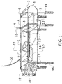
- a first embodiment ( Figure 1 ) comprising a structure anchored to the ground on which the barge moves in a continuous forward and backward movement so that it contacts a tank that is filled and emptied by the barge, said tank having a horizontally movable piston and a plate or tray that performs a lifting and lowering movement inside the tank alternately with the forward and backward movement of the piston, so that when the plate or tray descends into the lower chamber under the tank, a hydraulic cylinder placed under the tank is activated and this is what transmits the hydraulic energy to the means for transforming the hydraulic energy into kinetic energy and the latter into electrical energy.
- the means for transforming the energy of a water current into hydraulic energy also comprise a tank in combination with a plate or tray that has a lifting and lowering movement, with said tank having an associated swinging flap that causes the tank to sink and rise, and in this process, as in the previous case, each time the plate or tray lowers, the air contained in the chamber defined under the plate or tray freely escapes to the outside through the chimney.
- the tray loaded with the weight of the water serves to activate the hydraulic cylinder connected to the bottom of the tank, transmitting the hydraulic energy to the means for transforming the hydraulic energy into kinetic energy and the latter into electrical or mechanical energy.
- the means for transforming hydraulic energy into electrical energy ( figure 4 ) comprises a structure anchored to the ground on which a swinging structure is mounted and on this a pole that can be moved by the action of a hydraulic cylinder that receives the hydraulic energy from the means for transforming the energy of a water current, in such a way that by acting on the hydraulic cylinder the movable pole is moved and this produces the swinging of the swinging structure, on which a closed chain is mounted and to which a weight is attached.
- the weight is placed in a higher position and, due to the action of gravity, said weight falls, thus starting the generation of electrical energy by transforming the potential energy of the weight into the kinetic energy of rotation and this, in turn, into electrical energy.
- Our recommended case involves using the great potential of the force of the weight of water that is produced on a tray or plate when it is filled with water at the top, inside a tank, where this force or work is carried out. At the end of the cycle, the water is emptied so that the next cycle can be carried out again.
- the emptying of the tank ( figure 1 ), as the entire flow is in movement, is carried out with the force of the barge that moves at the same speed as the water flow, mounted for this function, pushing the water from the inside towards the flow of the river and starting a new cycle, having to position the gates open to avoid friction with the water in its backward movement and return to its initial position.
- This emptying can also be carried out through pipes of a suitable diameter buried laterally or through the centre and bottom of the flow until the difference in level is reached, due to its weight metres below.
- Figure 1 shows a first embodiment of the means for transforming the energy of a water current into hydraulic energy, comprising a rectangular structure (1) formed by guides along which a barge (15) runs by means of wheels (22) in a continuous forward and backward movement from an upstream end to a downstream end where a tank (5) is located.
- the rectangular structure (1) is anchored to the ground by means of foundation posts (11) or augers (16).
- the barge (15) has front gates (17) and rear gates (21) that are duly synchronised in their opening and closing and are operated by means of micromotors. Both the front gates (17) and the rear gates (21) are in a closed position forming a block during the advance of the barge (15), while during the return to the original position they open and remain in a parallel position to avoid friction with the water current.
- the tank (5) is housed inside a casing or cover (8) and the front part of the tank (5) has an external gate (2) that allows water to pass into the tank through its upper part and an internal gate (3), which allows water to enter the inside of the tank (5). Also, the rear part of the tank (5) has some gates (6) for the closing and exit of the water through an outlet opening (7).
- This outlet opening (7) is hermetically coupled with semiunderground pipes for emptying the water under its own weight when it reaches the difference in level metres below, mainly on slopes.
- a piston (10) that performs a horizontal movement, as well as a lifting and lowering tray or plate (9) where the forward and backward movements of the piston (10) alternate with the lifting and lowering movement of the tray or plate (9).
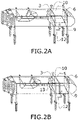
- Figure 2A shows the different positions of the tray (9) and the piston (10). In figure 2A the tray is raised and the piston (10) is retracted and in figure 2B the tray (9) is in its lower position and the piston (10) is in a forward position.
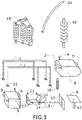
- FIG. 3 shows all the above parts exploded in order to better understand their construction details.
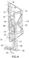
- FIG 4 shows the electricity generating assembly consisting of a swinging structure (23) anchored to the ground by means of columns or pillars (27) anchored to the ground by means of a foundation base (29).
- This swinging structure (23) has a mast or pole (34) that can be moved by means of bushings or clamps (34) mounted on the swinging structure (23) and said pole (34) can be moved by means of a hydraulic cylinder (35), the swinging structure (23) having fixed stops (36) that limit the displacement of the movable pole (29).
- the mast or movable pole (34) has a series of counterweights (33) and (38) placed at the ends of the movable pole (34).
- the counterweights (33) and (38) are necessary to achieve the balance of the pole (34). Although there is a loss in the displacement of the counterweights, the displacement of the balance point, which is reached by means of the hydraulic cylinder (35) attached to the pole, is considerably reduced.
- the swinging structure (23) rotates 180° in one direction and in the opposite direction with respect to an axis (26).
- This swinging structure (23) has a series of sprockets (24) on which a chain (32) runs and to which a weight (31) is attached which, when lowered, produces the rotation of a sprocket (25) fitted with pulleys to transmit the rotation to a generator.
- the hydraulic energy required to drive the hydraulic cylinder (35) comes from a pipe or hose (28) which in turn is connected to a hydraulic pump (30) to which the hydraulic pipe (20) is connected.
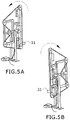
- Figures 5A and 5B show the two positions that the swinging structure (23) can adopt and that each time it rotates the weight (31) is lowered from its highest position to the lower position and during this displacement the movement of the chain is transformed into a rotation of the sprocket (25) so that by means of pulleys it transmits the rotation to a generator.
- Figure 8 shows the second embodiment of the means used to transform the kinetic energy of a water current and the potential energy of the weight of the water into hydraulic energy, consisting of a tank (5) with gates (40) in its lower part, wherein inside the tank (5) there is the plate or tray (9) with a lifting and lowering movement.
- the tank is linked to a swinging flap (39), where this flap (39) has a central opening in which the tank (5) is housed in an articulated manner.
- the flap assembly (39) and the tank (5) which is connected to a beam (42) that is hingedly connected to a support post (41) so as to allow the lifting and lowering of the tank (5) and flap (39) assembly.
Landscapes
- Engineering & Computer Science (AREA)
- Chemical & Material Sciences (AREA)
- Combustion & Propulsion (AREA)
- Mechanical Engineering (AREA)
- General Engineering & Computer Science (AREA)
- Power Engineering (AREA)
- Other Liquid Machine Or Engine Such As Wave Power Use (AREA)
Abstract
Description
- The object of the present invention, as the title of the invention states, is a system for generating electrical energy from the energy of a water current by means of a hydraulic wreck, which allows the transformation of the kinetic energy of a water current in movement, as well as the transformation of the potential energy of the very weight of the water into kinetic energy of a transformer assembly for its transformation into electrical energy.
- The present invention therefore falls within the field of equipment for transforming kinetic and potential energy into electrical energy, and in particular those that use the energy of water currents.
- Currently, hydraulic systems for producing energy are based on the movement of turbines by the force of water in large waterfalls, or on steam at high temperatures and pressures, also in the movement of turbines, like in different thermal power stations.
- Systems for harnessing tidal energy by turbining on site are also known; however, the known systems that harness the energy of water currents in rivers and canals without any additional construction such as dams and the like are scarce and have reduced energy production, where the flora and fauna of the watercourses are also affected.
- Therefore, the object of the present invention is to overcome the drawbacks of energy production systems based on the use of water currents, both in their kinetic and potential energy, since they require the construction of complex structures, as well as affect the ecosystem, by developing a hydraulic wreck such as the one described below, which is essentially described in the first claim.
- This system for producing electrical energy makes use of the moving water of rivers, canals, seas or any other form of water movement.
- The improvement comprising the invention is characterised in that it is powered only by moving water from rivers, canals, seas or others, without the use of exhaustible raw materials or environmental pollutants.
- Another improvement is that as its entire structure is submerged and its operation is not aggressive, noisy or affecting the landscape, not only does it have zero degrees of pollution, but it is also favourable and serves as a wreck, as its title indicates, to protect all fish fauna. The raw material will always be there, unless the water does not flow, due to extreme droughts or catastrophes, which will always be local and coincidental.
- The system for generating electrical energy from the energy of a water current comprises means for transforming the energy of a water current into hydraulic energy connected to means for transforming the hydraulic energy into kinetic energy and the latter into electrical energy.
- The means for transforming the energy of a water current into hydraulic energy can be carried out in two different ways.
- A first embodiment (
Figure 1 ) comprising a structure anchored to the ground on which the barge moves in a continuous forward and backward movement so that it contacts a tank that is filled and emptied by the barge, said tank having a horizontally movable piston and a plate or tray that performs a lifting and lowering movement inside the tank alternately with the forward and backward movement of the piston, so that when the plate or tray descends into the lower chamber under the tank, a hydraulic cylinder placed under the tank is activated and this is what transmits the hydraulic energy to the means for transforming the hydraulic energy into kinetic energy and the latter into electrical energy. - In a second embodiment (
figure 8 ), the means for transforming the energy of a water current into hydraulic energy also comprise a tank in combination with a plate or tray that has a lifting and lowering movement, with said tank having an associated swinging flap that causes the tank to sink and rise, and in this process, as in the previous case, each time the plate or tray lowers, the air contained in the chamber defined under the plate or tray freely escapes to the outside through the chimney. At that moment, the tray loaded with the weight of the water serves to activate the hydraulic cylinder connected to the bottom of the tank, transmitting the hydraulic energy to the means for transforming the hydraulic energy into kinetic energy and the latter into electrical or mechanical energy. - The means for transforming hydraulic energy into electrical energy (
figure 4 ) comprises a structure anchored to the ground on which a swinging structure is mounted and on this a pole that can be moved by the action of a hydraulic cylinder that receives the hydraulic energy from the means for transforming the energy of a water current, in such a way that by acting on the hydraulic cylinder the movable pole is moved and this produces the swinging of the swinging structure, on which a closed chain is mounted and to which a weight is attached. Each time the swinging structure rotates, the weight is placed in a higher position and, due to the action of gravity, said weight falls, thus starting the generation of electrical energy by transforming the potential energy of the weight into the kinetic energy of rotation and this, in turn, into electrical energy. - Our recommended case involves using the great potential of the force of the weight of water that is produced on a tray or plate when it is filled with water at the top, inside a tank, where this force or work is carried out. At the end of the cycle, the water is emptied so that the next cycle can be carried out again.
- The emptying of the tank (
figure 1 ), as the entire flow is in movement, is carried out with the force of the barge that moves at the same speed as the water flow, mounted for this function, pushing the water from the inside towards the flow of the river and starting a new cycle, having to position the gates open to avoid friction with the water in its backward movement and return to its initial position. This emptying can also be carried out through pipes of a suitable diameter buried laterally or through the centre and bottom of the flow until the difference in level is reached, due to its weight metres below. - Unless otherwise stated, all technical and scientific elements used herein have the meaning usually understood by a person skilled in the art to which this invention pertains. In the practice of the present invention, processes and materials similar or equivalent to those described herein may be used.
- Throughout the description and the claims, the word "comprises" and its variants are not intended to exclude other technical features, additives, components or steps. For those skilled in the art, other objects, advantages and features of the invention will be apparent in part from the description and in part from the practice of the invention.
- To complement the description being made and to help make the features of the invention more readily understandable, in accordance with a preferred practical exemplary embodiment thereof, a set of drawings is attached hereto as an integral part of said description, in which the following is depicted in an illustrative and non-limiting manner.
-
Figure 1 depicts the structural platform assembly of the hydraulic wreck in a front elevation view. -
Figures 2A and 2B showfigure 1 in two different sequences pertaining to the tray (9) and the piston (10) and different positions of the trays and the piston. -
Figure 3 shows an exploded view of the set of parts that make up the structure infigure 1 , allowing a better understanding of its shape and fit within the assembly. -
Figure 4 represents the assembly for transforming potential energy fromfigures 1 or8 into kinetic energy to be controlled and easily transformable. -
Figures 5A and 5B show the two positions that the swinging structure of the assembly for transforming potential energy can take. -
Figure 6 is an exploded representation of the main parts of that make up the assembly for transforming energy infigure 4 . -
Figure 7 represents the combination of the first embodiment for transforming the energy of a water current into hydraulic energy together with a transformation assembly. -
Figure 8 shows a front view of the second embodiment for transforming the energy of a water current into hydraulic energy. -
Figure 9 shows the set of parts of the second embodiment shown infigure 8 . - In view of the figures, a preferred embodiment of the proposed invention is described below.
-
Figure 1 shows a first embodiment of the means for transforming the energy of a water current into hydraulic energy, comprising a rectangular structure (1) formed by guides along which a barge (15) runs by means of wheels (22) in a continuous forward and backward movement from an upstream end to a downstream end where a tank (5) is located. - The rectangular structure (1) is anchored to the ground by means of foundation posts (11) or augers (16).
- In the front part of the structure (1) there is a set of rollers (19) formed by rotating wheels (18) that prevent branches or other objects that could be carried by the current from coming into contact with the barge (15) and the tank (5).
- The barge (15) has front gates (17) and rear gates (21) that are duly synchronised in their opening and closing and are operated by means of micromotors. Both the front gates (17) and the rear gates (21) are in a closed position forming a block during the advance of the barge (15), while during the return to the original position they open and remain in a parallel position to avoid friction with the water current.
- The tank (5) is housed inside a casing or cover (8) and the front part of the tank (5) has an external gate (2) that allows water to pass into the tank through its upper part and an internal gate (3), which allows water to enter the inside of the tank (5). Also, the rear part of the tank (5) has some gates (6) for the closing and exit of the water through an outlet opening (7). This outlet opening (7) is hermetically coupled with semiunderground pipes for emptying the water under its own weight when it reaches the difference in level metres below, mainly on slopes.
- Inside the tank (5) there is a piston (10) that performs a horizontal movement, as well as a lifting and lowering tray or plate (9) where the forward and backward movements of the piston (10) alternate with the lifting and lowering movement of the tray or plate (9).
- In the upper part of the tank (5) there is a pipe or chimney (4) for air inlet and outlet to avoid the formation of a vacuum inside the tank (5), while in the lower part of the tank (5) there is a hydraulic cylinder (12) that transmits the pressure through the hydraulic pipe (20). This hydraulic cylinder (12) has a piston associated with the tray or plate (9).
- When the barge (15) is in its previous position, the front gates (17) and rear gates (21) are closed and it starts to move along the guides until it contacts a stop (14), which is connected to a rod (13) and this rod (13) to the piston (10) so that it starts to move forward, causing the outlet gates (6) to open and the water to exit the tank and the air to enter through the chimney (4) to avoid the formation of a vacuum inside the tank. The air circulates through valves inside the tank until it is expelled, then the gates (6) close and the piston (10) starts a backward movement to its origin, at which point the tray or plate (9) begins to rise to its highest point, at which point the gate (2) opens and water begins to enter the tank (5) and the tray or plate (9) begins to lower and the hydraulic cylinder (12) begins to transmit hydraulic pressure.
-
Figure 2A shows the different positions of the tray (9) and the piston (10). Infigure 2A the tray is raised and the piston (10) is retracted and infigure 2B the tray (9) is in its lower position and the piston (10) is in a forward position. -
Figure 3 shows all the above parts exploded in order to better understand their construction details. -
Figure 4 shows the electricity generating assembly consisting of a swinging structure (23) anchored to the ground by means of columns or pillars (27) anchored to the ground by means of a foundation base (29). This swinging structure (23) has a mast or pole (34) that can be moved by means of bushings or clamps (34) mounted on the swinging structure (23) and said pole (34) can be moved by means of a hydraulic cylinder (35), the swinging structure (23) having fixed stops (36) that limit the displacement of the movable pole (29). On the other hand, the mast or movable pole (34) has a series of counterweights (33) and (38) placed at the ends of the movable pole (34). - The counterweights (33) and (38) are necessary to achieve the balance of the pole (34). Although there is a loss in the displacement of the counterweights, the displacement of the balance point, which is reached by means of the hydraulic cylinder (35) attached to the pole, is considerably reduced.
- The swinging structure (23) rotates 180° in one direction and in the opposite direction with respect to an axis (26). This swinging structure (23) has a series of sprockets (24) on which a chain (32) runs and to which a weight (31) is attached which, when lowered, produces the rotation of a sprocket (25) fitted with pulleys to transmit the rotation to a generator.
- The hydraulic energy required to drive the hydraulic cylinder (35) comes from a pipe or hose (28) which in turn is connected to a hydraulic pump (30) to which the hydraulic pipe (20) is connected.
-
Figures 5A and 5B show the two positions that the swinging structure (23) can adopt and that each time it rotates the weight (31) is lowered from its highest position to the lower position and during this displacement the movement of the chain is transformed into a rotation of the sprocket (25) so that by means of pulleys it transmits the rotation to a generator. -
Figure 8 shows the second embodiment of the means used to transform the kinetic energy of a water current and the potential energy of the weight of the water into hydraulic energy, consisting of a tank (5) with gates (40) in its lower part, wherein inside the tank (5) there is the plate or tray (9) with a lifting and lowering movement. The tank is linked to a swinging flap (39), where this flap (39) has a central opening in which the tank (5) is housed in an articulated manner. - The flap assembly (39) and the tank (5) which is connected to a beam (42) that is hingedly connected to a support post (41) so as to allow the lifting and lowering of the tank (5) and flap (39) assembly.
- In a first position, when the tank (5) together with the flap are at their highest level, the current contacts the rear end (39) of the flap, causing it to swing, which causes its front end to sink and therefore the tank (5), starting the entry of water into the tank (5), which in this case is open at the top. The entry of water causes the plate or tray (9) to lower and the air contained in the part below the plate or tray (9) exits through the chimney (4). When the plate or tray (9) is lowered, the hydraulic cylinder (12) is charged and, by means of the hydraulic pipe (20), transmits this energy to the hydraulic cylinder (35) in such a way that the swinging structure (23) swings, leaving the weight (31) in its upper part and ready to start lowering.
- The nature of the present invention having been sufficiently described, as well as the manner of putting it into practice, it should be noted that, within its essential nature, it may be put into practice in other embodiments which differ in detail from the one indicated by way of example, and to which the protection claimed will also apply, provided that it does not alter, change or modify its fundamental principle.
Claims (4)
- A system for generating electrical energy from the energy of a water current, characterised in that the means for transforming the energy of a water current into hydraulic energy comprise a rectangular structure (1) formed by guides along which a barge (15) runs by means of wheels (22) along which it can move in a continuous forward and backward movement from an upstream end to a downstream end where a tank (5) is located, wherein the barge (15) has front gates (17) and other rear gates (21) that are duly synchronised in their opening and closing and are operated by means of micromotors; furthermore, the front part of the tank (5) has an external gate (2) that allows water to pass into the tank through its upper part and an internal gate (3) which, when opened, allows water to enter the tank (5); also, the rear part of the tank (5) has some gates (6) for the closing and exit of the water through an outlet opening (7); on the other hand, inside the tank (5) there is a piston (10) that performs a horizontal movement, as well as a lifting and lowering tray or plate (9) where the forward and backward movements of the piston (10) alternate with the lifting and lowering movement of the tray or plate (9), and in the upper part of the tank (5) there is a pipe or chimney (4) for air inlet and outlet to avoid the formation of a vacuum inside the tank (5), while in the lower part of the tank (5) there is a hydraulic cylinder (12) that transmits the pressure through a hydraulic pipe (20) to the hydraulic cylinder (35) in such a way that the swinging structure (23) swings, leaving the weight (31) in its upper part and ready to start lowering.
- The system for generating electrical energy from the energy of a water current according to claim 1, characterised in that the rectangular structure (1) is anchored to the ground by means of foundation posts (11) or augers (16).
- The system for generating electrical energy from the energy of a water current according to claim 1, characterised in that in the front part of the structure (1) there is a set of rollers (19) formed by rotating wheels (18) that prevent branches or other objects that could be carried by the current from coming into contact with the barge (15) and the tank (5).
- The system for generating electrical energy from the energy of a water current according to any of claims 1 to 3, characterised in that it comprises means for transforming the energy of a water current into hydraulic energy, connected to means for transforming hydraulic energy into kinetic energy and the latter into electrical energy, wherein the means for transforming the hydraulic energy into kinetic energy and this into electrical energy comprise a swinging structure (23) anchored to the ground by means of columns or pillars (27) anchored to the ground by means of a foundation base (29), wherein this swinging structure (23) has a mast or pole (34) that can be moved by means of bushings or clamps (34) mounted on the swinging structure (23) and said pole (34) can be moved by means of a hydraulic cylinder (35), the swinging structure (23) has fixed stops (36) that limit the displacement of the movable pole (34); on the other hand, the mast or movable pole (34) has a series of counterweights (33) and (38) placed at the ends of the movable pole (34), wherein the swinging structure (23) rotates 180° in one direction and in the opposite direction with respect to an axis (26) and has a series of sprockets (24) on which a chain (32) runs and to which a weight (31) is attached which, when lowered, produces the rotation of a sprocket (25) fitted with pulleys to transmit the rotation to a generator, wherein the hydraulic energy required to drive the hydraulic cylinder (35) comes from a pipe or hose (28) which in turn is connected to a hydraulic pump (30) to which a hydraulic pipe (20) is connected.
Applications Claiming Priority (2)
| Application Number | Priority Date | Filing Date | Title |
|---|---|---|---|
| ES201931088A ES2831868B2 (en) | 2019-12-05 | 2019-12-05 | Electric power generation system from the energy of a water current |
| PCT/ES2020/070702 WO2021111018A1 (en) | 2019-12-05 | 2020-11-12 | System for generating electrical energy from the energy of a water current |
Publications (3)
| Publication Number | Publication Date |
|---|---|
| EP4071347A1 true EP4071347A1 (en) | 2022-10-12 |
| EP4071347A4 EP4071347A4 (en) | 2023-12-06 |
| EP4071347B1 EP4071347B1 (en) | 2026-01-07 |
Family
ID=76213466
Family Applications (1)
| Application Number | Title | Priority Date | Filing Date |
|---|---|---|---|
| EP20895437.0A Active EP4071347B1 (en) | 2019-12-05 | 2020-11-12 | System for generating electrical energy from the energy of a water current |
Country Status (3)
| Country | Link |
|---|---|
| EP (1) | EP4071347B1 (en) |
| ES (1) | ES2831868B2 (en) |
| WO (1) | WO2021111018A1 (en) |
Family Cites Families (5)
| Publication number | Priority date | Publication date | Assignee | Title |
|---|---|---|---|---|
| US4583368A (en) * | 1985-07-24 | 1986-04-22 | Neuenschwander Victor L | Water-powered hydraulic motor |
| US6945042B1 (en) * | 2004-08-27 | 2005-09-20 | Walckner James R | System for generating fluid movement |
| ES2302652B1 (en) * | 2007-10-22 | 2009-11-11 | Enric Pedro Palomer | INSTALLATION FOR THE GENERATION OF ELECTRICAL ENERGY THROUGH HYDROSTATIC PUSHING. |
| DE102012017265A1 (en) * | 2012-08-31 | 2014-03-06 | Hans Hinterding | Natural power pressure water tank is naturally filled by the flow stream of water and is again filled in submerged position by corresponding pipes, where inner pressure in natural power pressure water tank is increased to over pressure |
| US9909556B2 (en) * | 2014-12-31 | 2018-03-06 | Joseph Marion Santos | System for collecting energy from a moving mass |
-
2019
- 2019-12-05 ES ES201931088A patent/ES2831868B2/en active Active
-
2020
- 2020-11-12 EP EP20895437.0A patent/EP4071347B1/en active Active
- 2020-11-12 WO PCT/ES2020/070702 patent/WO2021111018A1/en not_active Ceased
Also Published As
| Publication number | Publication date |
|---|---|
| EP4071347B1 (en) | 2026-01-07 |
| EP4071347A4 (en) | 2023-12-06 |
| ES2831868B2 (en) | 2022-04-06 |
| ES2831868A1 (en) | 2021-06-09 |
| WO2021111018A1 (en) | 2021-06-10 |
Similar Documents
| Publication | Publication Date | Title |
|---|---|---|
| US3927330A (en) | Water power machine and under sea, under water generator station | |
| US7969033B2 (en) | Buoyancy energy cell | |
| US4034565A (en) | Method and apparatus for generating power | |
| US5374850A (en) | Apparatus and method for tidal and wave generation of power | |
| US8424300B1 (en) | Sea electricity energy production unit | |
| JPS61501730A (en) | water pneumatic hydraulic engine | |
| US4185464A (en) | Ocean tide energy converter having improved efficiency | |
| CN101769225B (en) | Lift-type double floating body tidal power generating platform | |
| JP7191232B2 (en) | Highly functional gravity moment hydroelectric system | |
| CN112334649B (en) | Power plant using buoyant body and power generation method thereof | |
| CN105408622A (en) | Submersible hydroelectric generator apparatus and method of draining water from such apparatus | |
| US20070176429A1 (en) | Water power generator | |
| US20240151205A1 (en) | Power amplification, storage and regeneration system and method using tides, waves and/or wind | |
| WO2007004290A1 (en) | Power generating plant using piston type turbine | |
| JP2020139494A (en) | Hydroelectric power generator | |
| EP4071347B1 (en) | System for generating electrical energy from the energy of a water current | |
| EP2032841A1 (en) | Apparatus for conversion of energy | |
| WO2025030822A1 (en) | Hydroelectric power generation and energy storage device based on water level variation | |
| CN100462554C (en) | Floating double-floor ocean wave power generation device | |
| AU2018342752B2 (en) | Method and apparatus of extracting energy from water waves to generate electric power | |
| WO2024121544A1 (en) | Apparatus and method | |
| AU2019246939A1 (en) | Apparatuses, systems, and methods for extraction and/or storage of energy from moving fluids | |
| WO2015015325A1 (en) | Hydropower generation mechanism using reciprocating machine having the capability of obtaining maximum energy of the water | |
| KR100792779B1 (en) | Buoyancy Generator | |
| KR20090076534A (en) | Buoyancy |
Legal Events
| Date | Code | Title | Description |
|---|---|---|---|
| STAA | Information on the status of an ep patent application or granted ep patent |
Free format text: STATUS: THE INTERNATIONAL PUBLICATION HAS BEEN MADE |
|
| PUAI | Public reference made under article 153(3) epc to a published international application that has entered the european phase |
Free format text: ORIGINAL CODE: 0009012 |
|
| STAA | Information on the status of an ep patent application or granted ep patent |
Free format text: STATUS: REQUEST FOR EXAMINATION WAS MADE |
|
| 17P | Request for examination filed |
Effective date: 20220630 |
|
| AK | Designated contracting states |
Kind code of ref document: A1 Designated state(s): AL AT BE BG CH CY CZ DE DK EE ES FI FR GB GR HR HU IE IS IT LI LT LU LV MC MK MT NL NO PL PT RO RS SE SI SK SM TR |
|
| DAV | Request for validation of the european patent (deleted) | ||
| DAX | Request for extension of the european patent (deleted) | ||
| A4 | Supplementary search report drawn up and despatched |
Effective date: 20231108 |
|
| RIC1 | Information provided on ipc code assigned before grant |
Ipc: F03B 17/06 20060101ALI20231102BHEP Ipc: F03B 5/00 20060101ALI20231102BHEP Ipc: F03B 13/00 20060101ALI20231102BHEP Ipc: F03B 17/00 20060101AFI20231102BHEP |
|
| GRAP | Despatch of communication of intention to grant a patent |
Free format text: ORIGINAL CODE: EPIDOSNIGR1 |
|
| STAA | Information on the status of an ep patent application or granted ep patent |
Free format text: STATUS: GRANT OF PATENT IS INTENDED |
|
| INTG | Intention to grant announced |
Effective date: 20250910 |
|
| RIN1 | Information on inventor provided before grant (corrected) |
Inventor name: PEREZ FERNANDEZ, CELSO |
|
| GRAS | Grant fee paid |
Free format text: ORIGINAL CODE: EPIDOSNIGR3 |
|
| GRAA | (expected) grant |
Free format text: ORIGINAL CODE: 0009210 |
|
| STAA | Information on the status of an ep patent application or granted ep patent |
Free format text: STATUS: THE PATENT HAS BEEN GRANTED |
|
| AK | Designated contracting states |
Kind code of ref document: B1 Designated state(s): AL AT BE BG CH CY CZ DE DK EE ES FI FR GB GR HR HU IE IS IT LI LT LU LV MC MK MT NL NO PL PT RO RS SE SI SK SM TR |
|
| REG | Reference to a national code |
Ref country code: CH Ref legal event code: F10 Free format text: ST27 STATUS EVENT CODE: U-0-0-F10-F00 (AS PROVIDED BY THE NATIONAL OFFICE) Effective date: 20260107 Ref country code: GB Ref legal event code: FG4D |
|
| REG | Reference to a national code |
Ref country code: DE Ref legal event code: R096 Ref document number: 602020065365 Country of ref document: DE |
|
| REG | Reference to a national code |
Ref country code: IE Ref legal event code: FG4D |
|
| REG | Reference to a national code |
Ref country code: NL Ref legal event code: MP Effective date: 20260107 |
|
| PG25 | Lapsed in a contracting state [announced via postgrant information from national office to epo] |
Ref country code: NL Free format text: LAPSE BECAUSE OF FAILURE TO SUBMIT A TRANSLATION OF THE DESCRIPTION OR TO PAY THE FEE WITHIN THE PRESCRIBED TIME-LIMIT Effective date: 20260107 |
|
| REG | Reference to a national code |
Ref country code: AT Ref legal event code: MK05 Ref document number: 1875757 Country of ref document: AT Kind code of ref document: T Effective date: 20260107 |
|
| PG25 | Lapsed in a contracting state [announced via postgrant information from national office to epo] |
Ref country code: RS Free format text: LAPSE BECAUSE OF FAILURE TO SUBMIT A TRANSLATION OF THE DESCRIPTION OR TO PAY THE FEE WITHIN THE PRESCRIBED TIME-LIMIT Effective date: 20260407 |
|
| PG25 | Lapsed in a contracting state [announced via postgrant information from national office to epo] |
Ref country code: ES Free format text: LAPSE BECAUSE OF FAILURE TO SUBMIT A TRANSLATION OF THE DESCRIPTION OR TO PAY THE FEE WITHIN THE PRESCRIBED TIME-LIMIT Effective date: 20260107 |
|
| PG25 | Lapsed in a contracting state [announced via postgrant information from national office to epo] |
Ref country code: PL Free format text: LAPSE BECAUSE OF FAILURE TO SUBMIT A TRANSLATION OF THE DESCRIPTION OR TO PAY THE FEE WITHIN THE PRESCRIBED TIME-LIMIT Effective date: 20260107 |
|
| PG25 | Lapsed in a contracting state [announced via postgrant information from national office to epo] |
Ref country code: GR Free format text: LAPSE BECAUSE OF FAILURE TO SUBMIT A TRANSLATION OF THE DESCRIPTION OR TO PAY THE FEE WITHIN THE PRESCRIBED TIME-LIMIT Effective date: 20260408 |
|
| REG | Reference to a national code |
Ref country code: LT Ref legal event code: MG9D |
|
| PG25 | Lapsed in a contracting state [announced via postgrant information from national office to epo] |
Ref country code: LT Free format text: LAPSE BECAUSE OF FAILURE TO SUBMIT A TRANSLATION OF THE DESCRIPTION OR TO PAY THE FEE WITHIN THE PRESCRIBED TIME-LIMIT Effective date: 20260107 |
|
| PG25 | Lapsed in a contracting state [announced via postgrant information from national office to epo] |
Ref country code: NO Free format text: LAPSE BECAUSE OF FAILURE TO SUBMIT A TRANSLATION OF THE DESCRIPTION OR TO PAY THE FEE WITHIN THE PRESCRIBED TIME-LIMIT Effective date: 20260407 |
|
| PG25 | Lapsed in a contracting state [announced via postgrant information from national office to epo] |
Ref country code: SE Free format text: LAPSE BECAUSE OF FAILURE TO SUBMIT A TRANSLATION OF THE DESCRIPTION OR TO PAY THE FEE WITHIN THE PRESCRIBED TIME-LIMIT Effective date: 20260107 Ref country code: AT Free format text: LAPSE BECAUSE OF FAILURE TO SUBMIT A TRANSLATION OF THE DESCRIPTION OR TO PAY THE FEE WITHIN THE PRESCRIBED TIME-LIMIT Effective date: 20260107 Ref country code: FI Free format text: LAPSE BECAUSE OF FAILURE TO SUBMIT A TRANSLATION OF THE DESCRIPTION OR TO PAY THE FEE WITHIN THE PRESCRIBED TIME-LIMIT Effective date: 20260107 |
|
| PG25 | Lapsed in a contracting state [announced via postgrant information from national office to epo] |
Ref country code: HR Free format text: LAPSE BECAUSE OF FAILURE TO SUBMIT A TRANSLATION OF THE DESCRIPTION OR TO PAY THE FEE WITHIN THE PRESCRIBED TIME-LIMIT Effective date: 20260107 |
|
| PG25 | Lapsed in a contracting state [announced via postgrant information from national office to epo] |
Ref country code: IS Free format text: LAPSE BECAUSE OF FAILURE TO SUBMIT A TRANSLATION OF THE DESCRIPTION OR TO PAY THE FEE WITHIN THE PRESCRIBED TIME-LIMIT Effective date: 20260507 Ref country code: PT Free format text: LAPSE BECAUSE OF FAILURE TO SUBMIT A TRANSLATION OF THE DESCRIPTION OR TO PAY THE FEE WITHIN THE PRESCRIBED TIME-LIMIT Effective date: 20260507 |
|
| PG25 | Lapsed in a contracting state [announced via postgrant information from national office to epo] |
Ref country code: LV Free format text: LAPSE BECAUSE OF FAILURE TO SUBMIT A TRANSLATION OF THE DESCRIPTION OR TO PAY THE FEE WITHIN THE PRESCRIBED TIME-LIMIT Effective date: 20260107 |
|
| PG25 | Lapsed in a contracting state [announced via postgrant information from national office to epo] |
Ref country code: BG Free format text: LAPSE BECAUSE OF FAILURE TO SUBMIT A TRANSLATION OF THE DESCRIPTION OR TO PAY THE FEE WITHIN THE PRESCRIBED TIME-LIMIT Effective date: 20260107 |