EP4071310A1 - Operation support server, operation support system, and operation support method - Google Patents
Operation support server, operation support system, and operation support method Download PDFInfo
- Publication number
- EP4071310A1 EP4071310A1 EP21756181.0A EP21756181A EP4071310A1 EP 4071310 A1 EP4071310 A1 EP 4071310A1 EP 21756181 A EP21756181 A EP 21756181A EP 4071310 A1 EP4071310 A1 EP 4071310A1
- Authority
- EP
- European Patent Office
- Prior art keywords
- warm
- work machine
- time
- designated
- state variable
- Prior art date
- Legal status (The legal status is an assumption and is not a legal conclusion. Google has not performed a legal analysis and makes no representation as to the accuracy of the status listed.)
- Granted
Links
Images




Classifications
-
- H—ELECTRICITY
- H04—ELECTRIC COMMUNICATION TECHNIQUE
- H04Q—SELECTING
- H04Q9/00—Arrangements in telecontrol or telemetry systems for selectively calling a substation from a main station, in which substation desired apparatus is selected for applying a control signal thereto or for obtaining measured values therefrom
-
- E—FIXED CONSTRUCTIONS
- E02—HYDRAULIC ENGINEERING; FOUNDATIONS; SOIL SHIFTING
- E02F—DREDGING; SOIL-SHIFTING
- E02F9/00—Component parts of dredgers or soil-shifting machines, not restricted to one of the kinds covered by groups E02F3/00 - E02F7/00
- E02F9/20—Drives; Control devices
- E02F9/2025—Particular purposes of control systems not otherwise provided for
- E02F9/205—Remotely operated machines, e.g. unmanned vehicles
-
- E—FIXED CONSTRUCTIONS
- E02—HYDRAULIC ENGINEERING; FOUNDATIONS; SOIL SHIFTING
- E02F—DREDGING; SOIL-SHIFTING
- E02F9/00—Component parts of dredgers or soil-shifting machines, not restricted to one of the kinds covered by groups E02F3/00 - E02F7/00
- E02F9/20—Drives; Control devices
- E02F9/22—Hydraulic or pneumatic drives
- E02F9/226—Safety arrangements, e.g. hydraulic driven fans, preventing cavitation, leakage, overheating
-
- E—FIXED CONSTRUCTIONS
- E02—HYDRAULIC ENGINEERING; FOUNDATIONS; SOIL SHIFTING
- E02F—DREDGING; SOIL-SHIFTING
- E02F9/00—Component parts of dredgers or soil-shifting machines, not restricted to one of the kinds covered by groups E02F3/00 - E02F7/00
- E02F9/26—Indicating devices
-
- E—FIXED CONSTRUCTIONS
- E02—HYDRAULIC ENGINEERING; FOUNDATIONS; SOIL SHIFTING
- E02F—DREDGING; SOIL-SHIFTING
- E02F9/00—Component parts of dredgers or soil-shifting machines, not restricted to one of the kinds covered by groups E02F3/00 - E02F7/00
- E02F9/26—Indicating devices
- E02F9/267—Diagnosing or detecting failure of vehicles
-
- E—FIXED CONSTRUCTIONS
- E02—HYDRAULIC ENGINEERING; FOUNDATIONS; SOIL SHIFTING
- E02F—DREDGING; SOIL-SHIFTING
- E02F3/00—Dredgers; Soil-shifting machines
- E02F3/04—Dredgers; Soil-shifting machines mechanically-driven
- E02F3/28—Dredgers; Soil-shifting machines mechanically-driven with digging tools mounted on a dipper- or bucket-arm, i.e. there is either one arm or a pair of arms, e.g. dippers, buckets
- E02F3/36—Component parts
- E02F3/42—Drives for dippers, buckets, dipper-arms or bucket-arms
- E02F3/43—Control of dipper or bucket position; Control of sequence of drive operations
- E02F3/435—Control of dipper or bucket position; Control of sequence of drive operations for dipper-arms, backhoes or the like
Definitions
- the present invention relates to a technique for a warm-up operation of a work machine.
- Patent Literatures 1 to 2 A technique for performing a warm-up operation depending on a temperature of a hydraulic system of a work machine or a construction machine has been proposed (see, e.g., Patent Literatures 1 to 2).
- the operator when an operator remotely operates a work machine, the operator does not easily recognize a status of the work machine. For example, if the work machine is positioned at a location where an air temperature is low, a warm-up operation needs to be performed before work by the work machine is started. However, the operator does not notice the necessity of the warm-up operation because he/she is at a location spaced apart from the work machine. The operator cannot immediately begin the work even in an attempt to start the work by the work machine.
- the present invention is directed to providing a technique capable of starting a warm-up operation of a work machine in view of scheduled use of the work machine and an external state variable of the work machine.
- An operation support server comprises
- the predicted value of the internal state variable representing the state of the component in the work machine at the designated time is estimated based on the time series of the predicted values of the external state variable over the period until the designated time.
- the "external state variable” is a variable that affects the internal state variable of the work machine and represents an environment of the work machine.
- the "internal state variable” is a variable that changes in value depending on the warm-up operation of the work machine and represents a state of a designated component among components in the work machine.
- the "designated time” is a concept containing a time designated by a user such as an operator of the work machine or a director who supervises an operation state of the work machine or any time included in a period to be designated by the user.
- the warm-up operation of the work machine is started at a time before the designated time based on communication with the work machine such that the predicted value of the internal state variable of the work machine at the designated time satisfies the designated condition. Accordingly, the operator can start work at the designated time using the work machine the internal state variable of which satisfies the designated condition.
- An operation support system as an embodiment of the present invention illustrated in FIG. 1 comprises an operation support server 10 and a work machine 40 to be remotely operated by a remote operation apparatus 20 (a client).
- the operation support server 10, the remote operation apparatus 20, the work machine 40, and a client 60 are configured to be network-communicable with one another.
- An intercommunication network between the operation support server 10 and the remote operation apparatus 20 and an intercommunication network between the operation support server 10 and the work machine 40 may be the same as or different from each other.
- the operation support server 10 comprises a database 102, a first support processing element 121, and a second support processing element 122.
- the database 102 stores and holds an operation schedule of the work machine 40.
- the database 102 may store and hold picked-up image data, for example, in addition to the operation schedule.
- the database 102 may be constituted by a database server separate from the operation support server 10.
- Each of the support processing elements is constituted by an arithmetic processing unit (a single core processor or a multi-core processor or a processor core constituting the processor), and reads required data and software from a storage device such as a memory and performs arithmetic processing, described below, conforming to the software with the data used as a target.
- the remote operation apparatus 20 comprises a remote control device 200, a remote input interface 210, and a remote output interface 220.
- the remote operation apparatus 20 functions as at least one of a "first client" and a "second client”.
- the remote control device 200 is constituted by an arithmetic processing unit (a single core processor or a multi-core processor or a processor core constituting the processor), and reads required data and software from a storage device such as a memory and performs arithmetic processing conforming to the software with the data used as a target.
- the remote input interface 210 comprises a remote operation mechanism 211.
- the remote output interface 220 comprises an image output device 221 and remote wireless communication equipment 222.
- the remote operation mechanism 211 includes a traveling operation device, a turning operation device, a boom operation device, an arm operation device, and a bucket operation device.
- Each of the operation devices has an operation lever that receives a rotation operation.
- the operation lever (traveling lever) of the traveling operation device is operated to move a lower traveling body 410 in the work machine 40.
- the traveling lever may also serve as a traveling pedal.
- An operation lever (turning lever) of the turning operation device is operated to move a turning mechanism 430 in the work machine 40.
- An operation lever (boom lever) of the boom operation device is operated to move a boom cylinder 442 in the work machine 40.
- An operation lever (arm lever) of the arm operation device is operated to move an arm cylinder 444 in the work machine 40.
- An operation lever (bucket lever) of the bucket operation device is operated to move a bucket cylinder 446 in the work machine 40.
- Each of the operation levers constituting the remote operation mechanism 211 is arranged around a seat St for an operator to sit, as illustrated in FIG. 2 , for example.
- the seat St has a form such as a high back chair with armrests
- the seat St may be a seating portion in any form in which the operator can sit, for example, a form like a low back chair with no headrest or a form like a chair with no backrest.
- a pair of left and right traveling levers 2110 respectively corresponding to left and right crawlers are laterally arranged side by side in front of the seat St.
- One operation lever may also serve as a plurality of operation levers.
- a left-side operation lever 2111 provided in front of a left-side frame of the seat St illustrated in FIG. 2 may function as an arm lever when operated in a front-rear direction and function as a turning lever when operated in a left-right direction.
- a right-side operation lever 2112 provided in front of a right-side frame of the seat St illustrated in FIG. 2 may function as a boom lever when operated in the front-rear direction and function as a bucket lever when operated in the left-right direction.
- a lever pattern may be arbitrarily changed in response to an operation instruction of the operator.
- the image output device 221 comprises a central image output device 2210, a left-side image output device 2211, and a right-side image output device 2212 respectively having substantially rectangular screens arranged in front of, diagonally leftward in front of, and diagonally rightward in front of the seat St, as illustrated in FIG. 2 , for example. Respective shapes and sizes of the screens (image display regions) of the central image output device 2210, the left-side image output device 2211, and the right-side image output device 2212 may be the same as or different from one another.
- a right edge of the left-side image output device 2211 is adjacent to a left edge of the central image output device 2210 such that the screen of the central image output device 2210 and the screen of the left-side image output device 2211 form an inclined angle ⁇ 1 (e.g., 120° ⁇ ⁇ 1 ⁇ 150°).
- a left edge of the right-side image output device 2212 is adjacent to a right edge of the central image output device 2210 such that the screen of the central image output device 2210 and the screen of the right-side image output device 2212 form an inclined angle ⁇ 2 (e.g., 120° ⁇ ⁇ 2 ⁇ 150°).
- the inclined angles ⁇ 1 and ⁇ 2 may be the same as or different from each other.
- the respective screens of the central image output device 2210, the left-side image output device 2211, and the right-side image output device 2212 may be parallel to one another in a vertical direction, or may be inclined in the vertical direction. At least one of the central image output device 2210, the left-side image output device 2211, and the right-side image output device 2212 may be constituted by a plurality of separated image output devices.
- the central image output device 2210 may be constituted by a pair of image output devices, which are vertically adjacent to each other, each having a substantially rectangular screen.
- Each of the image output devices 2210 to 2212 may further comprise a speaker (voice output device).
- the work machine 40 comprises an actual machine control device 400, an actual machine input interface 41, an actual machine output interface 42, and an actuation mechanism 440.
- the actual machine control device 400 is constituted by an arithmetic processing unit (a single core processor or a multi-core processor or a processor core constituting the processor), and reads required data and software from a storage device such as a memory and performs arithmetic processing conforming to the software with the data used as a target.
- arithmetic processing unit a single core processor or a multi-core processor or a processor core constituting the processor
- the work machine 40 is a crawler shovel (construction machine), for example, and comprises a crawler type lower traveling body 410 and an upper turning body 420 turnably loaded on the lower traveling body 410 via the turning mechanism 430 as shown in FIG. 3 .
- a front left side portion of the upper turning body 420 is provided with a cab 424 (an operation room).
- a front central portion of the upper turning body 420 is provided with the work attachment 440.
- the actual machine input interface 41 comprises an actual machine operation mechanism 411, an actual machine image pickup device 412, and a positioning device 414.
- the actual machine operation mechanism 411 comprises a plurality of actual machine operation levers arranged similarly to the remote operation mechanism 211 around a seat arranged in the cab 424.
- the cab 424 is provided with a driving mechanism or a robot that receives a signal corresponding to an operation mode of the remote operation mechanism 211 and moves the actual machine operation levers based on the received signal.
- the actual machine image pickup device 412 is installed in the cab 424, for example, and picks up images of environments including at least a part of the actuation mechanism 440 through a front window and a pair of left and right side windows. Some or all of the front window and the side windows may be omitted.
- the positioning device 414 is constituted by a GNSS receiver (GNSS: Global Navigation Satellite System) configured to detect an existence position of the work machine 40.
- GNSS Global Navigation Satellite System
- the actual machine output interface 42 comprises actual machine wireless communication equipment 422 configured to network-communicate with the operation support server 10, the remote operation apparatus 20, and the client 60.
- the work attachment 440 as the actuation mechanism comprises a boom 441 mounted on the upper turning body 420 to be raisable and lowerable, an arm 443 rotatably connected to a distal end of the boom 441, and a bucket 445 rotatably connected to a distal end of the arm 443.
- the boom cylinder 442, the arm cylinder 444, and the bucket cylinder 446 each constituted by a stretchable hydraulic cylinder are mounted on the work attachment 440.
- the boom cylinder 442 is interposed between the boom 441 and the upper turning body 420 by expanding and contracting upon being supplied with hydraulic oil to rotate the boom 441 in a rise and fall direction.
- the arm cylinder 444 is interposed between the arm 443 and the boom 441 by expanding and contracting upon being supplied with hydraulic oil to rotate the arm 443 around a horizontal axis relative to the boom 441.
- the bucket cylinder 446 is interposed between the bucket 445 and the arm 443 by expanding and contracting upon being supplied with hydraulic oil to rotate the bucket 445 around a horizontal axis relative to the arm 443.
- the work machine 40 comprises an internal state recognition unit 460.
- the internal state recognition unit 460 includes, for example, a temperature sensor arranged in piping of engine cooling water for the work machine 40, a temperature sensor arranged in hydraulic piping, a tank, or the like in a hydraulic system configured to operate the turning mechanism 430 and the work attachment 440, and a temperature sensor arranged in another component in the work machine 40.
- the client 60 is a terminal device such as a smartphone, a tablet terminal, or a personal computer, and comprises a control device 600, an input interface 610, and an output interface 620.
- the client 60 functions as at least one of the "first client” and the "second client".
- the control device 600 is constituted by an arithmetic processing unit (a single core processor or a multi-core processor or a processor core constituting the processor), and reads required data and software from a storage device such as a memory and performs arithmetic processing conforming to the software with the data used as a target.
- the input interface 610 is constituted by a button and a switch of a touch panel type, for example.
- the output interface 620 comprises an image output device and wireless communication equipment.
- the presence or absence of a first designation operation through the remote input interface 210 by the operator is determined ( FIG. 4 /STEP210).
- the "first designation operation” is an operation for selecting the work machine 40 that cooperates with the remote operation apparatus 20.
- the presence or absence of the first designation operation is determined in the following manner, for example.
- a map and/or a list representing respective existence positions of work machines 40 that can cooperate with the remote operation apparatus 20, for example, are/is outputted to the remote output interface 220.
- a result of the determination is negative ( FIG. 4 /NO in STEP210)
- processing subsequent to the determination of the presence or absence of the first designation operation is repeated.
- a designated time t of the work machine 40 that cooperates with the remote operation apparatus 20 is set by the operator ( FIG. 4 /STEP211).
- the designated time t is a scheduled time when the remote operation apparatus 20 starts work by the work machine 40.
- the set designated time t is stored and held in the database 102.
- an operation request is transmitted to the operation support server 10 through the remote wireless communication equipment 222 ( FIG. 4 /STEP212).
- the request includes a work machine identifier for identifying the work machine 40 which has established communication with the remote operation apparatus 20 or the work machine 40 designated through the remote input interface 210, and the set designated time t.
- the first support processing element 121 transmits a state confirmation request to the work machine 40 to be identified by the work machine identifier ( FIG. 4 /STEP110).
- the actual machine control device 400 recognizes position information (a latitude and a longitude) of the work machine 40 through the positioning device 414 ( FIG. 4 /STEP410).
- the actual machine control device 400 transmits the position information or position data representing the position information to the remote operation apparatus 20 through the actual machine wireless communication equipment 422 ( FIG. 4 /STEP411).
- the first support processing element 121 recognizes the position information ( FIG. 4 /C11).
- the state confirmation request to the work machine 40 by the operation support server 10 ( FIG. 4 /STEP110) and the recognition of the position information ( FIG. 4 /C11) may be omitted.
- the operation support server 10 if the first support processing element 121 recognizes the position information ( FIG. 4 /C11), a measurement value of an external state variable is recognized based on the position information ( FIG. 4 /STEP111).
- the "external state variable" is a variable that affects an internal state variable of the work machine 40 and represents an environment of the work machine 40.
- an air temperature around the work machine 40 corresponds to the external state variable.
- the "internal state variable” is a variable representing a state of a component in the work machine.
- a temperature of a designated component corresponds to the internal state variable.
- An example of the "temperature of the designated component” is a water temperature T1 in piping of engine cooling water for the work machine 40, a temperature T2 of hydraulic piping, a tank, or the like in a hydraulic system for operating the turning mechanism 430 and the work attachment 440, and a temperature of another component in the work machine 40, such that measured by the internal state recognition unit 460, and is a temperature of the component in the work machine 40 that changes depending on an outside air temperature of the work machine 40 with an engine as a power source of the work machine 40 not operated.
- the first support processing element 121 refers, based on position information of the work machine 40, weather information of a position represented by the position information or an area including the position to a weather information database as an external information source, to recognize the measurement value of the external state variable ( FIG. 4 /STEP111).
- the weather information database is provided by a licensed forecasting service operator, and includes past data and prediction data of weather at any point across the country.
- the first support processing element 121 recognizes weather information corresponding to the position of the work machine 40 over several hours (e.g., six hours) before a current time t1 until the designated time t, for example. If the external state variable is an air temperature, a time series of measurement values of the air temperature over several hours until the current time t1 and a time series of predicted values of the air temperature from the current time t1 to the designated time t are recognized.
- the second support processing element 122 calculates a warm-up operation start time t2 ( FIG. 4 /STEP112).
- the second support processing element 122 recognizes a predicted value (predicted temperature) of the temperature of the designated component with the work machine 40 not used.
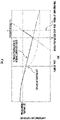
- the temperature of the designated component is substantially the same as the outside air temperature. However, if the work machine 40 has not been used and if the outside air temperature varies, for example, the temperature of the designated component varies. As illustrated in FIG. 6 , when the outside air temperature decreases, the temperature of the designated component also decreases. However, if the outside air temperature gently decreases (or increases), the outside air temperature and the temperature of the designated component are substantially the same. On the other hand, if the outside air temperature rapidly decreases (or increases), a difference occurs between the outside air temperature and the temperature of the designated component.
- the second support processing element 122 calculates, assuming that there occurs a temperature difference between the outside air temperature and the temperature of the designated component as illustrated in FIG. 6 when a rate of change F1 (°C/min) of the temperature per unit time of the designated component has a threshold value and there is a rate of change F2 (°C/min) of the outside air temperature per unit time exceeding the threshold value, the temperature difference.
- the rate of change F1 corresponds to a heat transfer rate when there is a temperature difference between the designated component and the outside air temperature, and the threshold value of the rate of change F1 can be previously recognized or estimated by past actual results of the work machine 40, simulation, and the like.
- the first support processing element 121 recognizes a temperature change of the designated component with the engine of the work machine 40 not operated from the current time t1 to at least the designated time t based on the outside air temperature recognized from the weather information database and the calculated temperature difference.
- the second support processing element 122 previously recognizes or estimates a warm-up capability of the work machine 40 by past actual results, simulation, and the like.
- the warm-up capability of the work machine 40 is recognized as a temperature increase rate F3 (°C/min) per unit time of the designated component, for example.
- the second support processing element 122 calculates the warm-up operation start time t2 based on the time series of the predicted values of the temperature of the designated component from the current time t1 to the designated time t, the warm-up capability of the work machine 40, and the designated time t. The calculation considers a function of drawing heat from the designated component by outside air until a warm-up operation is started, and considers that a function of warming the designated component by heat of the engine is overwhelmingly larger than the function of drawing heat from the designated component by outside air when the warm-up operation is started and the engine is operated.
- the second support processing element 122 recognizes the time series of the predicted values of the temperature of the designated component in a period from the current time t1 to the designated time t as described above.
- the designated component having the estimated temperature at each of time points is warm-up operated in the warm-up capability F3 (°C/min) of the machine, a time point where warm-up is completed at the designated time t is specified as the warm-up start time t2.
- a straight line having an inclination of the warm-up capability F3 (°C/min) can be illustrated to pass through a point that reaches a predetermined temperature at a warm-up completion time t3.
- the estimated temperature of the designated component continues to decrease until the warm-up operation start time t2, the estimated temperature continues to increase at F3 (°C/min) after the warm-up operation start time t2 and increases to a predetermined temperature at the warm-up completion time t3.
- the second support processing element 122 may specify as the warm-up start time t2 a time point where warm-up is completed immediately before (set to be one to five minutes before, for example) the designated time t in order to reliably complete the warm-up at the designated time t.
- the prediction accuracy of the temperature of the designated component can be enhanced by adding an element (an atmospheric pressure, a wind speed, a humidity, a rainfall, a snowfall, etc.) other than the air temperature as an external state variable.
- an element an atmospheric pressure, a wind speed, a humidity, a rainfall, a snowfall, etc.
- the second support processing element 122 calculates the warm-up operation start time t2 ( FIG. 4 /STEP112), and transmits a warm-up delay notification ( FIG. 4 /STEP114) when the warm-up completion time t3 is later than the designated time t ( FIG. 4 /NO in STEP113).
- the remote operation apparatus 20/the client 60 outputs the warm-up delay notification to the output interface 220 when it receives the warm-up delay notification ( FIG. 4 /C22), and notifies the operator that the warm-up has not been completed at the time point of the designated time t ( FIG. 4 /STEP213). If a sufficient warm-up time period cannot be ensured between the current time t1 and the designated time t, the processing is performed. At this time, the warm-up completion time t3 to be estimated may be outputted to the remote output interface 220.
- the second support processing element 122 transmits a warm-up operation command to the work machine 40 ( FIG. 4 /STEP116) when the warm-up operation start time t2 is reached.
- the warm-up operation command includes a command to instruct the work machine 40 to perform warm-up, and may additionally include the designated time t. If the time point where the warm-up is completed is later than the designated time t ( FIG. 4 /NO in STEP113), the current time t1 is set to the warm-up operation start time t2, and the warm-up operation command is immediately transmitted to the work machine 40.
- the actual machine control device 400 recognizes the measurement value of the temperature of the designated component using the internal state recognition unit 460 ( FIG. 4 /STEP414).
- the actual machine control device 400 starts the warm-up operation depending on the measurement value of the temperature of the designated component ( FIG. 4 /STEP416).
- the actual machine control device 400 predicts the warm-up completion time t3 when the warm-up operation is completed such that the temperature of the designated component satisfies a designated condition based on the measurement value of the temperature of the designated component and the warm-up capability of the work machine 40, shifts the warm-up start time t2 to a warm-up start time t2' as illustrated in FIG. 7 to delay start of the warm-up operation when the warm-up completion time t3 is earlier than the designated time t, or gently performs the warm-up (suppresses the warm-up capability) as illustrated in FIG. 8 not to cause fuel consumption until the designated time t since the warm-up operation was completed.
- the determination whether or not the measurement value of the internal state variable satisfies the designated condition may be performed depending on the number of engine revolution and/or the frequency of an engine sound of the work machine 40.
- the number of revolutions and/or the frequency do/does not fall within a predetermined range.
- the number of revolutions and/or the frequency fall/falls within the predetermined range.
- the warm-up is started at the time point where the warm-up operation command is received, and can determine that the warm-up is completed when the warm-up can be continued until the designated time t.
- the second support processing element 122 transmits the warm-up completion notification to the remote operation apparatus 20 ( FIG. 4 /STEP119) when it receives the warm-up completion notification ( FIG. 4 /C12).
- the remote control device 200 receives the warm-up completion notification ( FIG. 4 /C22), the warm-up completion notification is outputted to the image output device 221 constituting the remote output interface 220 and/or the client 60 ( FIG. 4 /STEP214). As a result, the warm-up completion notification is outputted immediately before the designated time t, and the operator can recognize that the warm-up of the work machine 40 has been completed.
- the presence or absence of a second designation operation through the remote input interface 210 by the operator is determined ( FIG. 5 /STEP 220).
- An example of the "second designation operation” is an operation such as a tap in the remote input interface 210 configured to designate the work machine 40 remote operation of which is intended by the operator. If a result of the determination is negative ( FIG. 5 /NO in STEP220), processing subsequent to the determination of the presence or absence of the designation operation is repeated. On the other hand, if the result of the determination is affirmative ( FIG. 5 /YES in STEP220), an environment confirmation request is transmitted to the operation support server 10 through the remote wireless communication equipment 222 ( FIG. 5 /STEP222).
- the first support processing element 121 transmits the environment confirmation request to the corresponding work machine 40 ( FIG. 5 /C13).
- the actual machine control device 400 recognizes a picked-up image through the actual machine image pickup device 412 ( FIG. 5 /STEP420).
- the actual machine control device 400 transmits picked-up image data representing the picked-up image to the remote operation apparatus 20 through the actual machine wireless communication equipment 422 ( FIG. 5 /STEP422).
- the second support processing element 122 transmits environment image data corresponding to the picked-up image to the remote operation apparatus 20 ( FIG. 5 /STEP120).
- the environment image data is not only the picked-up image data itself but also image data representing a simulated environment image generated based on the picked-up image.
- the remote control device 200 In the remote operation apparatus 20, if the environment image data is received through the remote wireless communication equipment 222 ( FIG. 5 /C24), the remote control device 200 outputs an environment image corresponding to the environment image data to the image output device 221 ( FIG. 5 /STEP224).
- an environment image on which a boom 441, an arm 443, and a bucket 445, respectively, as parts of the work attachment 440 are reflected is outputted to the image output device 221, as illustrated in FIG. 9 , for example.
- the remote control device 200 recognizes an operation mode of the remote operation mechanism 211 ( FIG. 5 /STEP226), and transmits a remote operation command corresponding to the operation mode to the operation support server 10 through the remote wireless communication equipment 222 ( FIG. 5 /STEP228).
- the second support processing element 122 receives the remote operation command
- the first support processing element 121 transmits the remote operation command to the work machine 40 ( FIG. 5 /C15).
- the actual machine control device 400 receives the operation command through the actual machine wireless communication equipment 422 ( FIG. 5 /C43), an operation of the work attachment 440 or the like is controlled ( FIG. 5 /STEP424).
- the remote operation of the work machine 40 is started at the time t3 or later, as illustrated in FIG. 6 .
- the warm-up operation is completed. For example, work for scooping soil in front of the work machine 40 using the bucket 445 and dropping the soil from the bucket 445 after turning the upper turning body 420 is performed.
- a predicted value of a temperature (internal state variable) of a designated component in the work machine 40 at a designated time t is recognized based on a time series of predicted values of an outside air temperature (external state variable) around the work machine 40 over a period until the designated time t.
- a warm-up operation of the work machine 40 is started at a time before the designated time t based on communication with the work machine 40 such that the predicted value of the temperature of the designated component in the work machine 40 at the designated time t satisfies a designated condition (see FIG. 4 /YES in STEP113 ⁇ STEP116 ⁇ ... ⁇ STEP416). Accordingly, the operator can start work at the designated time t or a time close thereto using the work machine 40 in which the temperature of the designated component satisfies the designated condition.
- the first support processing element 121 recognizes a warm-up capability when the work machine 40 performs the warm-up operation
- the second support processing element 122 predicts a warm-up completion time t3 when the predicted value of the internal state variable satisfies the designated condition based on the warm-up capability of the work machine 40 recognized by the first support processing element 121 and performs processing for causing the work machine 40 to start the warm-up operation based on communication with the work machine 40 in order to make a warm-up completion time t3 match the designated time t.
- the warm-up completion time t3 is predicted in view of the warm-up capability of the work machine 40. Processing for causing the work machine 40 to start the warm-up operation is performed in order to make the warm-up completion time t3 match or come close to the designated time t. However, the warm-up completion time t3 is not completely the same as the designated time t, and may be a time slightly before the designated time t.
- a warm-up operation period elapsed until a value of the temperature (internal state variable) of the designated component satisfies the designated condition is shortened by an amount in which a time interval between the warm-up completion time t3 and the designated time t has been shortened, and thus energy consumption (or fuel consumption) required for the warm-up operation is reduced by the amount of the shortening.
- the second support processing element 122 outputs a warm-up delay notification to either one of the respective output interfaces 220 and 620 in the remote operation apparatus 20 and the client 60 based on communication with the remote operation apparatus 20 or the client 60 when the warm-up completion time t3 to be predicted when the warm-up operation of the work machine 40 is started at a current time is later than the designated time.
- the warm-up delay notification is outputted to either one of the respective remote output interfaces 220 and 620 in the remote operation apparatus 20 and the client 60 (see FIG. 4 /NO in STEP113 ⁇ STEP114 ⁇ STEP213).
- a notification that the warm-up completion time t3 when the predicted value of the temperature (internal state variable) of the designated component satisfies the designated condition is inevitably delayed can be transmitted to the operator or the like.
- the temperature (internal state variable) of the designated component is measured in the work machine, the warm-up completion time t3 is predicted based on the measurement value, and the work machine 40 starts the warm-up operation in order to make the warm-up completion time t3 match the designated time t (see FIG. 4 /STEP414 ⁇ STEP416).
- the warm-up operation period elapsed until the value of the internal state variable satisfies the designated condition is shortened by an amount in which the time interval between the warm-up completion time t3 and the designated time t is shortened with high accuracy, and thus energy consumption (or fuel consumption) required for the warm-up operation is reduced by the amount of the shortening.
- the second support processing element 122 transmits the warm-up operation command to the work machine 40 (see FIG. 4 /STEP116).
- a second support processing element 122 may transmit a warm-up operation command including a warm-up start time t2 to a work machine 40.
- the warm-up operation command is received ( FIG. 4 /C41)
- an actual machine control device 400 starts a warm-up operation at the warm-up operation start time t2 ( FIG. 4 /STEP416).
- the actual machine control device 400 predicts a warm-up completion time t3 based on a measurement value of a temperature of a designated component in the work machine 40 and a warm-up capability of the work machine 40. If the warm-up completion time t3 is earlier than a designated time t, a warm-up operation is performed by delaying start of the warm-up operation or reducing the warm-up capability.
- a warm-up operation period elapsed until a value of a temperature (internal state variable) of the designated component satisfies a designated condition is shortened by an amount in which a time interval between the warm-up completion time t3 and a designated time t has been shortened, and thus energy consumption (or fuel consumption) required for the warm-up operation is reduced by the amount of the shortening.
- 10...operation support server 20...remote operation apparatus, 40...work machine, 41...actual machine input interface, 42...actual machine output interface, 102...database, 121...first support processing element, 122...second support processing element, 200...remote control device, 210...remote input interface, 211...remote operation mechanism, 220...remote output interface, 221...image output device, 400...actual machine control device, 424...cab (operation room), 440...work attachment (actuation mechanism), 445...bucket (work portion).
Landscapes
- Engineering & Computer Science (AREA)
- Mining & Mineral Resources (AREA)
- Civil Engineering (AREA)
- General Engineering & Computer Science (AREA)
- Structural Engineering (AREA)
- Mechanical Engineering (AREA)
- Computer Networks & Wireless Communication (AREA)
- Operation Control Of Excavators (AREA)
- Component Parts Of Construction Machinery (AREA)
- Selective Calling Equipment (AREA)
Abstract
Description
- The present invention relates to a technique for a warm-up operation of a work machine.
- A technique for performing a warm-up operation depending on a temperature of a hydraulic system of a work machine or a construction machine has been proposed (see, e.g.,
Patent Literatures 1 to 2). -
- Patent Literature 1: Domestic re-publication of PCT international application No. 2019/053833
- Patent Literature 2:
Japanese Patent Laid-Open No. 2018-048472 - However, when an operator remotely operates a work machine, the operator does not easily recognize a status of the work machine. For example, if the work machine is positioned at a location where an air temperature is low, a warm-up operation needs to be performed before work by the work machine is started. However, the operator does not notice the necessity of the warm-up operation because he/she is at a location spaced apart from the work machine. The operator cannot immediately begin the work even in an attempt to start the work by the work machine.
- The present invention is directed to providing a technique capable of starting a warm-up operation of a work machine in view of scheduled use of the work machine and an external state variable of the work machine.
- An operation support server according to the present invention comprises
- a first support processing element configured to recognize a time series of predicted values of an external state variable representing an environment of a work machine over a period from a current time to a designated time as a scheduled work start time by the work machine based on communication with an external information source, and
- a second support processing element configured to recognize a predicted value at the designated time of an internal state variable representing a state of a component in the work machine to be affected by a warm-up operation mode of the work machine based on the time series of the predicted values of the external state variable recognized by the first support processing element and perform processing for causing the work machine to start a warm-up operation at a time before the designated time based on communication with the work machine such that the predicted value of the internal state variable at the designated time satisfies a designated condition.
- According to the operation support server having the configuration, the predicted value of the internal state variable representing the state of the component in the work machine at the designated time is estimated based on the time series of the predicted values of the external state variable over the period until the designated time. The "external state variable" is a variable that affects the internal state variable of the work machine and represents an environment of the work machine. The "internal state variable" is a variable that changes in value depending on the warm-up operation of the work machine and represents a state of a designated component among components in the work machine. The "designated time" is a concept containing a time designated by a user such as an operator of the work machine or a director who supervises an operation state of the work machine or any time included in a period to be designated by the user.
- The warm-up operation of the work machine is started at a time before the designated time based on communication with the work machine such that the predicted value of the internal state variable of the work machine at the designated time satisfies the designated condition. Accordingly, the operator can start work at the designated time using the work machine the internal state variable of which satisfies the designated condition.
-
-
FIG. 1 is an explanatory diagram relating to a configuration of an operation support system according to an embodiment of the present invention. -
FIG. 2 is an explanatory diagram relating to a configuration of a remote operation apparatus. -
FIG. 3 is an explanatory diagram relating to a configuration of a work machine. -
FIG. 4 is an explanatory diagram relating to a function of the operation support system. -
FIG. 5 is an explanatory diagram relating to a function of the operation support system. -
FIG. 6 is a diagram illustrating respective changes of an outside air temperature of the work machine and an estimated temperature of a designated component. -
FIG. 7 is a diagram illustrating a change in temperature of the designated component with warm-up of the work machine. -
FIG. 8 is a diagram illustrating a change in temperature of the designated component with warm-up of the work machine. -
FIG. 9 is an explanatory diagram relating to a work environment image. - An operation support system as an embodiment of the present invention illustrated in
FIG. 1 comprises anoperation support server 10 and awork machine 40 to be remotely operated by a remote operation apparatus 20 (a client). The operation supportserver 10, theremote operation apparatus 20, thework machine 40, and aclient 60 are configured to be network-communicable with one another. An intercommunication network between theoperation support server 10 and theremote operation apparatus 20 and an intercommunication network between theoperation support server 10 and thework machine 40 may be the same as or different from each other. - The
operation support server 10 comprises adatabase 102, a firstsupport processing element 121, and a secondsupport processing element 122. Thedatabase 102 stores and holds an operation schedule of thework machine 40. Thedatabase 102 may store and hold picked-up image data, for example, in addition to the operation schedule. Thedatabase 102 may be constituted by a database server separate from theoperation support server 10. Each of the support processing elements is constituted by an arithmetic processing unit (a single core processor or a multi-core processor or a processor core constituting the processor), and reads required data and software from a storage device such as a memory and performs arithmetic processing, described below, conforming to the software with the data used as a target. - The
remote operation apparatus 20 comprises aremote control device 200, aremote input interface 210, and aremote output interface 220. Theremote operation apparatus 20 functions as at least one of a "first client" and a "second client". Theremote control device 200 is constituted by an arithmetic processing unit (a single core processor or a multi-core processor or a processor core constituting the processor), and reads required data and software from a storage device such as a memory and performs arithmetic processing conforming to the software with the data used as a target. Theremote input interface 210 comprises aremote operation mechanism 211. Theremote output interface 220 comprises animage output device 221 and remotewireless communication equipment 222. - The
remote operation mechanism 211 includes a traveling operation device, a turning operation device, a boom operation device, an arm operation device, and a bucket operation device. Each of the operation devices has an operation lever that receives a rotation operation. The operation lever (traveling lever) of the traveling operation device is operated to move alower traveling body 410 in thework machine 40. The traveling lever may also serve as a traveling pedal. For example, a traveling pedal fixed to a base portion or a lower end portion of the traveling lever may be provided. An operation lever (turning lever) of the turning operation device is operated to move aturning mechanism 430 in thework machine 40. An operation lever (boom lever) of the boom operation device is operated to move aboom cylinder 442 in thework machine 40. An operation lever (arm lever) of the arm operation device is operated to move anarm cylinder 444 in thework machine 40. An operation lever (bucket lever) of the bucket operation device is operated to move abucket cylinder 446 in thework machine 40. - Each of the operation levers constituting the
remote operation mechanism 211 is arranged around a seat St for an operator to sit, as illustrated inFIG. 2 , for example. Although the seat St has a form such as a high back chair with armrests, the seat St may be a seating portion in any form in which the operator can sit, for example, a form like a low back chair with no headrest or a form like a chair with no backrest. - A pair of left and
right traveling levers 2110 respectively corresponding to left and right crawlers are laterally arranged side by side in front of the seat St. One operation lever may also serve as a plurality of operation levers. For example, a left-side operation lever 2111 provided in front of a left-side frame of the seat St illustrated inFIG. 2 may function as an arm lever when operated in a front-rear direction and function as a turning lever when operated in a left-right direction. Similarly, a right-side operation lever 2112 provided in front of a right-side frame of the seat St illustrated inFIG. 2 may function as a boom lever when operated in the front-rear direction and function as a bucket lever when operated in the left-right direction. A lever pattern may be arbitrarily changed in response to an operation instruction of the operator. - The
image output device 221 comprises a centralimage output device 2210, a left-sideimage output device 2211, and a right-sideimage output device 2212 respectively having substantially rectangular screens arranged in front of, diagonally leftward in front of, and diagonally rightward in front of the seat St, as illustrated inFIG. 2 , for example. Respective shapes and sizes of the screens (image display regions) of the centralimage output device 2210, the left-sideimage output device 2211, and the right-sideimage output device 2212 may be the same as or different from one another. - As illustrated in
FIG. 2 , a right edge of the left-sideimage output device 2211 is adjacent to a left edge of the centralimage output device 2210 such that the screen of the centralimage output device 2210 and the screen of the left-sideimage output device 2211 form an inclined angle θ1 (e.g., 120° ≤ θ1 ≤ 150°). As illustrated inFIG. 2 , a left edge of the right-sideimage output device 2212 is adjacent to a right edge of the centralimage output device 2210 such that the screen of the centralimage output device 2210 and the screen of the right-sideimage output device 2212 form an inclined angle θ2 (e.g., 120° ≤ θ2 ≤ 150°). The inclined angles θ1 and θ2 may be the same as or different from each other. - The respective screens of the central
image output device 2210, the left-sideimage output device 2211, and the right-sideimage output device 2212 may be parallel to one another in a vertical direction, or may be inclined in the vertical direction. At least one of the centralimage output device 2210, the left-sideimage output device 2211, and the right-sideimage output device 2212 may be constituted by a plurality of separated image output devices. For example, the centralimage output device 2210 may be constituted by a pair of image output devices, which are vertically adjacent to each other, each having a substantially rectangular screen. Each of theimage output devices 2210 to 2212 may further comprise a speaker (voice output device). - As illustrated in
FIG. 1 , thework machine 40 comprises an actualmachine control device 400, an actualmachine input interface 41, an actualmachine output interface 42, and anactuation mechanism 440. The actualmachine control device 400 is constituted by an arithmetic processing unit (a single core processor or a multi-core processor or a processor core constituting the processor), and reads required data and software from a storage device such as a memory and performs arithmetic processing conforming to the software with the data used as a target. - The
work machine 40 is a crawler shovel (construction machine), for example, and comprises a crawler typelower traveling body 410 and anupper turning body 420 turnably loaded on thelower traveling body 410 via theturning mechanism 430 as shown inFIG. 3 . A front left side portion of theupper turning body 420 is provided with a cab 424 (an operation room). A front central portion of theupper turning body 420 is provided with thework attachment 440. - The actual
machine input interface 41 comprises an actualmachine operation mechanism 411, an actual machineimage pickup device 412, and apositioning device 414. The actualmachine operation mechanism 411 comprises a plurality of actual machine operation levers arranged similarly to theremote operation mechanism 211 around a seat arranged in thecab 424. Thecab 424 is provided with a driving mechanism or a robot that receives a signal corresponding to an operation mode of theremote operation mechanism 211 and moves the actual machine operation levers based on the received signal. The actual machineimage pickup device 412 is installed in thecab 424, for example, and picks up images of environments including at least a part of theactuation mechanism 440 through a front window and a pair of left and right side windows. Some or all of the front window and the side windows may be omitted. Thepositioning device 414 is constituted by a GNSS receiver (GNSS: Global Navigation Satellite System) configured to detect an existence position of thework machine 40. - The actual
machine output interface 42 comprises actual machinewireless communication equipment 422 configured to network-communicate with theoperation support server 10, theremote operation apparatus 20, and theclient 60. - The
work attachment 440 as the actuation mechanism comprises aboom 441 mounted on theupper turning body 420 to be raisable and lowerable, anarm 443 rotatably connected to a distal end of theboom 441, and abucket 445 rotatably connected to a distal end of thearm 443. Theboom cylinder 442, thearm cylinder 444, and thebucket cylinder 446 each constituted by a stretchable hydraulic cylinder are mounted on thework attachment 440. - The
boom cylinder 442 is interposed between theboom 441 and theupper turning body 420 by expanding and contracting upon being supplied with hydraulic oil to rotate theboom 441 in a rise and fall direction. Thearm cylinder 444 is interposed between thearm 443 and theboom 441 by expanding and contracting upon being supplied with hydraulic oil to rotate thearm 443 around a horizontal axis relative to theboom 441. Thebucket cylinder 446 is interposed between thebucket 445 and thearm 443 by expanding and contracting upon being supplied with hydraulic oil to rotate thebucket 445 around a horizontal axis relative to thearm 443. - The
work machine 40 comprises an internalstate recognition unit 460. The internalstate recognition unit 460 includes, for example, a temperature sensor arranged in piping of engine cooling water for thework machine 40, a temperature sensor arranged in hydraulic piping, a tank, or the like in a hydraulic system configured to operate theturning mechanism 430 and thework attachment 440, and a temperature sensor arranged in another component in thework machine 40. - The
client 60 is a terminal device such as a smartphone, a tablet terminal, or a personal computer, and comprises acontrol device 600, aninput interface 610, and anoutput interface 620. Theclient 60 functions as at least one of the "first client" and the "second client". Thecontrol device 600 is constituted by an arithmetic processing unit (a single core processor or a multi-core processor or a processor core constituting the processor), and reads required data and software from a storage device such as a memory and performs arithmetic processing conforming to the software with the data used as a target. - The
input interface 610 is constituted by a button and a switch of a touch panel type, for example. Theoutput interface 620 comprises an image output device and wireless communication equipment. - In the remote operation apparatus 20 (or the client 60), the presence or absence of a first designation operation through the
remote input interface 210 by the operator is determined (FIG. 4 /STEP210). The "first designation operation" is an operation for selecting thework machine 40 that cooperates with theremote operation apparatus 20. The presence or absence of the first designation operation is determined in the following manner, for example. A map and/or a list representing respective existence positions ofwork machines 40 that can cooperate with theremote operation apparatus 20, for example, are/is outputted to theremote output interface 220. Then, it is determined whether an operation such as a tap, a swipe, or a pinching in theremote input interface 210 configured to designate the onework machine 40 that cooperates with theremote operation apparatus 20 has been performed by the operator. - If a result of the determination is negative (
FIG. 4 /NO in STEP210), processing subsequent to the determination of the presence or absence of the first designation operation is repeated. On the other hand, if the result of the determination is affirmative (FIG. 4 /YES in STEP210), a designated time t of thework machine 40 that cooperates with theremote operation apparatus 20 is set by the operator (FIG. 4 /STEP211). The designated time t is a scheduled time when theremote operation apparatus 20 starts work by thework machine 40. The set designated time t is stored and held in thedatabase 102. - Then, an operation request is transmitted to the
operation support server 10 through the remote wireless communication equipment 222 (FIG. 4 /STEP212). The request includes a work machine identifier for identifying thework machine 40 which has established communication with theremote operation apparatus 20 or thework machine 40 designated through theremote input interface 210, and the set designated time t. - In the
operation support server 10, if the operation request is received (FIG. 4 /C10), the firstsupport processing element 121 transmits a state confirmation request to thework machine 40 to be identified by the work machine identifier (FIG. 4 /STEP110). - In the
work machine 40, if the state confirmation request is received through the actual machine wireless communication equipment 422 (FIG. 4 /C40), the actualmachine control device 400 recognizes position information (a latitude and a longitude) of thework machine 40 through the positioning device 414 (FIG. 4 /STEP410). - The actual
machine control device 400 transmits the position information or position data representing the position information to theremote operation apparatus 20 through the actual machine wireless communication equipment 422 (FIG. 4 /STEP411). - In the
operation support server 10, the firstsupport processing element 121 recognizes the position information (FIG. 4 /C11). - If the position information of the
work machine 40 can be previously recognized (position information at the time of previous operation of thework machine 40 is stored and held in thedatabase 102, for example), the state confirmation request to thework machine 40 by the operation support server 10 (FIG. 4 /STEP110) and the recognition of the position information (FIG. 4 /C11) may be omitted. In theoperation support server 10, if the firstsupport processing element 121 recognizes the position information (FIG. 4 /C11), a measurement value of an external state variable is recognized based on the position information (FIG. 4 /STEP111). The "external state variable" is a variable that affects an internal state variable of thework machine 40 and represents an environment of thework machine 40. For example, an air temperature around thework machine 40 corresponds to the external state variable. The "internal state variable" is a variable representing a state of a component in the work machine. For example, a temperature of a designated component corresponds to the internal state variable. An example of the "temperature of the designated component" is a water temperature T1 in piping of engine cooling water for thework machine 40, a temperature T2 of hydraulic piping, a tank, or the like in a hydraulic system for operating theturning mechanism 430 and thework attachment 440, and a temperature of another component in thework machine 40, such that measured by the internalstate recognition unit 460, and is a temperature of the component in thework machine 40 that changes depending on an outside air temperature of thework machine 40 with an engine as a power source of thework machine 40 not operated. - For example, the first
support processing element 121 refers, based on position information of thework machine 40, weather information of a position represented by the position information or an area including the position to a weather information database as an external information source, to recognize the measurement value of the external state variable (FIG. 4 /STEP111). The weather information database is provided by a licensed forecasting service operator, and includes past data and prediction data of weather at any point across the country. - The first
support processing element 121 recognizes weather information corresponding to the position of thework machine 40 over several hours (e.g., six hours) before a current time t1 until the designated time t, for example. If the external state variable is an air temperature, a time series of measurement values of the air temperature over several hours until the current time t1 and a time series of predicted values of the air temperature from the current time t1 to the designated time t are recognized. - Then, the second
support processing element 122 calculates a warm-up operation start time t2 (FIG. 4 /STEP112). - If the external state variable is the air temperature, the second
support processing element 122 recognizes a predicted value (predicted temperature) of the temperature of the designated component with thework machine 40 not used. - If the
work machine 40 has not been used and if an outside air temperature around thework machine 40 is constant, for example, the temperature of the designated component is substantially the same as the outside air temperature. However, if thework machine 40 has not been used and if the outside air temperature varies, for example, the temperature of the designated component varies. As illustrated inFIG. 6 , when the outside air temperature decreases, the temperature of the designated component also decreases. However, if the outside air temperature gently decreases (or increases), the outside air temperature and the temperature of the designated component are substantially the same. On the other hand, if the outside air temperature rapidly decreases (or increases), a difference occurs between the outside air temperature and the temperature of the designated component. - The second
support processing element 122 calculates, assuming that there occurs a temperature difference between the outside air temperature and the temperature of the designated component as illustrated inFIG. 6 when a rate of change F1 (°C/min) of the temperature per unit time of the designated component has a threshold value and there is a rate of change F2 (°C/min) of the outside air temperature per unit time exceeding the threshold value, the temperature difference. The rate of change F1 corresponds to a heat transfer rate when there is a temperature difference between the designated component and the outside air temperature, and the threshold value of the rate of change F1 can be previously recognized or estimated by past actual results of thework machine 40, simulation, and the like. - The first
support processing element 121 recognizes a temperature change of the designated component with the engine of thework machine 40 not operated from the current time t1 to at least the designated time t based on the outside air temperature recognized from the weather information database and the calculated temperature difference. - The second
support processing element 122 previously recognizes or estimates a warm-up capability of thework machine 40 by past actual results, simulation, and the like. The warm-up capability of thework machine 40 is recognized as a temperature increase rate F3 (°C/min) per unit time of the designated component, for example. - The second
support processing element 122 calculates the warm-up operation start time t2 based on the time series of the predicted values of the temperature of the designated component from the current time t1 to the designated time t, the warm-up capability of thework machine 40, and the designated time t. The calculation considers a function of drawing heat from the designated component by outside air until a warm-up operation is started, and considers that a function of warming the designated component by heat of the engine is overwhelmingly larger than the function of drawing heat from the designated component by outside air when the warm-up operation is started and the engine is operated. - Specifically, the second
support processing element 122 recognizes the time series of the predicted values of the temperature of the designated component in a period from the current time t1 to the designated time t as described above. When the designated component having the estimated temperature at each of time points is warm-up operated in the warm-up capability F3 (°C/min) of the machine, a time point where warm-up is completed at the designated time t is specified as the warm-up start time t2. InFIG. 6 , a straight line having an inclination of the warm-up capability F3 (°C/min) can be illustrated to pass through a point that reaches a predetermined temperature at a warm-up completion time t3. Although the estimated temperature of the designated component continues to decrease until the warm-up operation start time t2, the estimated temperature continues to increase at F3 (°C/min) after the warm-up operation start time t2 and increases to a predetermined temperature at the warm-up completion time t3. - The second
support processing element 122 may specify as the warm-up start time t2 a time point where warm-up is completed immediately before (set to be one to five minutes before, for example) the designated time t in order to reliably complete the warm-up at the designated time t. - The prediction accuracy of the temperature of the designated component can be enhanced by adding an element (an atmospheric pressure, a wind speed, a humidity, a rainfall, a snowfall, etc.) other than the air temperature as an external state variable.
- The second
support processing element 122 calculates the warm-up operation start time t2 (FIG. 4 /STEP112), and transmits a warm-up delay notification (FIG. 4 /STEP114) when the warm-up completion time t3 is later than the designated time t (FIG. 4 /NO in STEP113). Theremote operation apparatus 20/theclient 60 outputs the warm-up delay notification to theoutput interface 220 when it receives the warm-up delay notification (FIG. 4 /C22), and notifies the operator that the warm-up has not been completed at the time point of the designated time t (FIG. 4 /STEP213). If a sufficient warm-up time period cannot be ensured between the current time t1 and the designated time t, the processing is performed. At this time, the warm-up completion time t3 to be estimated may be outputted to theremote output interface 220. - The second
support processing element 122 transmits a warm-up operation command to the work machine 40 (FIG. 4 /STEP116) when the warm-up operation start time t2 is reached. The warm-up operation command includes a command to instruct thework machine 40 to perform warm-up, and may additionally include the designated time t. If the time point where the warm-up is completed is later than the designated time t (FIG. 4 /NO in STEP113), the current time t1 is set to the warm-up operation start time t2, and the warm-up operation command is immediately transmitted to thework machine 40. - In the
work machine 40, if the warm-up operation command is received (FIG. 4 /C41), the actualmachine control device 400 recognizes the measurement value of the temperature of the designated component using the internal state recognition unit 460 (FIG. 4 /STEP414). The actualmachine control device 400 starts the warm-up operation depending on the measurement value of the temperature of the designated component (FIG. 4 /STEP416). - Specifically, the actual
machine control device 400 predicts the warm-up completion time t3 when the warm-up operation is completed such that the temperature of the designated component satisfies a designated condition based on the measurement value of the temperature of the designated component and the warm-up capability of thework machine 40, shifts the warm-up start time t2 to a warm-up start time t2' as illustrated inFIG. 7 to delay start of the warm-up operation when the warm-up completion time t3 is earlier than the designated time t, or gently performs the warm-up (suppresses the warm-up capability) as illustrated inFIG. 8 not to cause fuel consumption until the designated time t since the warm-up operation was completed. - It is determined whether or not the measurement value of the internal state variable satisfies the designated condition (
FIG. 4 /STEP418). Specifically, it is determined whether or not the temperature of an internal coefficient target has increased to a predetermined temperature. - If a result of the determination is negative (
FIG. 4 /NO in STEP418), processing for the determination is repeated. On the other hand, if the result of the determination is affirmative (FIG. 4 /YES in STEP418), a warm-up completion notification is transmitted to the operation support server 10 (FIG. 4 /STEP420). - The determination whether or not the measurement value of the internal state variable satisfies the designated condition may be performed depending on the number of engine revolution and/or the frequency of an engine sound of the
work machine 40. - Specifically, with the warm-up being insufficient, the number of revolutions and/or the frequency do/does not fall within a predetermined range. However, when the warm-up progresses, the number of revolutions and/or the frequency fall/falls within the predetermined range. Thus, when such a change is captured, the completion of the warm-up can be determined.
- If there is nothing corresponding to the internal
state recognition unit 460, the warm-up is started at the time point where the warm-up operation command is received, and can determine that the warm-up is completed when the warm-up can be continued until the designated time t. - The second
support processing element 122 transmits the warm-up completion notification to the remote operation apparatus 20 (FIG. 4 /STEP119) when it receives the warm-up completion notification (FIG. 4 /C12). - In the
remote operation apparatus 20, if theremote control device 200 receives the warm-up completion notification (FIG. 4 /C22), the warm-up completion notification is outputted to theimage output device 221 constituting theremote output interface 220 and/or the client 60 (FIG. 4 /STEP214). As a result, the warm-up completion notification is outputted immediately before the designated time t, and the operator can recognize that the warm-up of thework machine 40 has been completed. - A further function of the operation support system having the above-described configuration will be described with reference to a flowchart illustrated in
FIG. 5 . - In the
remote operation apparatus 20, the presence or absence of a second designation operation through theremote input interface 210 by the operator is determined (FIG. 5 /STEP 220). An example of the "second designation operation" is an operation such as a tap in theremote input interface 210 configured to designate thework machine 40 remote operation of which is intended by the operator. If a result of the determination is negative (FIG. 5 /NO in STEP220), processing subsequent to the determination of the presence or absence of the designation operation is repeated. On the other hand, if the result of the determination is affirmative (FIG. 5 /YES in STEP220), an environment confirmation request is transmitted to theoperation support server 10 through the remote wireless communication equipment 222 (FIG. 5 /STEP222). - In the
operation support server 10, if the environment confirmation request is received, the firstsupport processing element 121 transmits the environment confirmation request to the corresponding work machine 40 (FIG. 5 /C13). - In the
work machine 40, if the environment confirmation request is received through the actual machine wireless communication equipment 422 (FIG. 5 /C42), the actualmachine control device 400 recognizes a picked-up image through the actual machine image pickup device 412 (FIG. 5 /STEP420). The actualmachine control device 400 transmits picked-up image data representing the picked-up image to theremote operation apparatus 20 through the actual machine wireless communication equipment 422 (FIG. 5 /STEP422). - In the
operation support server 10, if the firstsupport processing element 121 receives the picked-up image data (FIG. 5 /C14), the secondsupport processing element 122 transmits environment image data corresponding to the picked-up image to the remote operation apparatus 20 (FIG. 5 /STEP120). The environment image data is not only the picked-up image data itself but also image data representing a simulated environment image generated based on the picked-up image. - In the
remote operation apparatus 20, if the environment image data is received through the remote wireless communication equipment 222 (FIG. 5 /C24), theremote control device 200 outputs an environment image corresponding to the environment image data to the image output device 221 (FIG. 5 /STEP224). - As a result, an environment image on which a
boom 441, anarm 443, and abucket 445, respectively, as parts of thework attachment 440 are reflected is outputted to theimage output device 221, as illustrated inFIG. 9 , for example. - In the
remote operation apparatus 20, theremote control device 200 recognizes an operation mode of the remote operation mechanism 211 (FIG. 5 /STEP226), and transmits a remote operation command corresponding to the operation mode to theoperation support server 10 through the remote wireless communication equipment 222 (FIG. 5 /STEP228). - In the
operation support server 10, if the secondsupport processing element 122 receives the remote operation command, the firstsupport processing element 121 transmits the remote operation command to the work machine 40 (FIG. 5 /C15). - In the
work machine 40, if the actualmachine control device 400 receives the operation command through the actual machine wireless communication equipment 422 (FIG. 5 /C43), an operation of thework attachment 440 or the like is controlled (FIG. 5 /STEP424). As a result, the remote operation of thework machine 40 is started at the time t3 or later, as illustrated inFIG. 6 . In this case, the warm-up operation is completed. For example, work for scooping soil in front of thework machine 40 using thebucket 445 and dropping the soil from thebucket 445 after turning theupper turning body 420 is performed. - According to the
operation support server 10 having the configuration, a predicted value of a temperature (internal state variable) of a designated component in thework machine 40 at a designated time t is recognized based on a time series of predicted values of an outside air temperature (external state variable) around thework machine 40 over a period until the designated time t. - A warm-up operation of the
work machine 40 is started at a time before the designated time t based on communication with thework machine 40 such that the predicted value of the temperature of the designated component in thework machine 40 at the designated time t satisfies a designated condition (seeFIG. 4 /YES in STEP113 → STEP116 → ... → STEP416). Accordingly, the operator can start work at the designated time t or a time close thereto using thework machine 40 in which the temperature of the designated component satisfies the designated condition. - The first
support processing element 121 recognizes a warm-up capability when thework machine 40 performs the warm-up operation, and the secondsupport processing element 122 predicts a warm-up completion time t3 when the predicted value of the internal state variable satisfies the designated condition based on the warm-up capability of thework machine 40 recognized by the firstsupport processing element 121 and performs processing for causing thework machine 40 to start the warm-up operation based on communication with thework machine 40 in order to make a warm-up completion time t3 match the designated time t. - The warm-up completion time t3 is predicted in view of the warm-up capability of the
work machine 40. Processing for causing thework machine 40 to start the warm-up operation is performed in order to make the warm-up completion time t3 match or come close to the designated time t. However, the warm-up completion time t3 is not completely the same as the designated time t, and may be a time slightly before the designated time t. A warm-up operation period elapsed until a value of the temperature (internal state variable) of the designated component satisfies the designated condition is shortened by an amount in which a time interval between the warm-up completion time t3 and the designated time t has been shortened, and thus energy consumption (or fuel consumption) required for the warm-up operation is reduced by the amount of the shortening. - The second
support processing element 122 outputs a warm-up delay notification to either one of therespective output interfaces remote operation apparatus 20 and theclient 60 based on communication with theremote operation apparatus 20 or theclient 60 when the warm-up completion time t3 to be predicted when the warm-up operation of thework machine 40 is started at a current time is later than the designated time. - Even if the warm-up operation of the work machine is started at the current time, when the warm-up completion time is later than the designated time, the warm-up delay notification is outputted to either one of the respective
remote output interfaces remote operation apparatus 20 and the client 60 (seeFIG. 4 /NO in STEP113 → STEP114 → STEP213). As a result, even if the warm-up operation of thework machine 40 is started immediately from the current time, a notification that the warm-up completion time t3 when the predicted value of the temperature (internal state variable) of the designated component satisfies the designated condition is inevitably delayed can be transmitted to the operator or the like. - The temperature (internal state variable) of the designated component is measured in the work machine, the warm-up completion time t3 is predicted based on the measurement value, and the
work machine 40 starts the warm-up operation in order to make the warm-up completion time t3 match the designated time t (seeFIG. 4 /STEP414 → STEP416). The warm-up operation period elapsed until the value of the internal state variable satisfies the designated condition is shortened by an amount in which the time interval between the warm-up completion time t3 and the designated time t is shortened with high accuracy, and thus energy consumption (or fuel consumption) required for the warm-up operation is reduced by the amount of the shortening. - In the present embodiment, when the current time reaches the warm-up operation start time t2, the second
support processing element 122 transmits the warm-up operation command to the work machine 40 (seeFIG. 4 /STEP116). However, in another embodiment, a secondsupport processing element 122 may transmit a warm-up operation command including a warm-up start time t2 to awork machine 40. In this case, in thework machine 40, if the warm-up operation command is received (FIG. 4 /C41), an actualmachine control device 400 starts a warm-up operation at the warm-up operation start time t2 (FIG. 4 /STEP416). At a time point where the warm-up operation command is received, the actualmachine control device 400 predicts a warm-up completion time t3 based on a measurement value of a temperature of a designated component in thework machine 40 and a warm-up capability of thework machine 40. If the warm-up completion time t3 is earlier than a designated time t, a warm-up operation is performed by delaying start of the warm-up operation or reducing the warm-up capability. A warm-up operation period elapsed until a value of a temperature (internal state variable) of the designated component satisfies a designated condition is shortened by an amount in which a time interval between the warm-up completion time t3 and a designated time t has been shortened, and thus energy consumption (or fuel consumption) required for the warm-up operation is reduced by the amount of the shortening. - 10...operation support server, 20...remote operation apparatus, 40...work machine, 41...actual machine input interface, 42...actual machine output interface, 102...database, 121...first support processing element, 122...second support processing element, 200...remote control device, 210...remote input interface, 211...remote operation mechanism, 220...remote output interface, 221...image output device, 400...actual machine control device, 424...cab (operation room), 440...work attachment (actuation mechanism), 445...bucket (work portion).
Claims (5)
- An operation support server comprising:a first support processing element configured to recognize a time series of predicted values of an external state variable representing an environment of a work machine over a period from a current time to a designated time as a scheduled work start time by the work machine based on communication with an external information source; anda second support processing element configured to recognize a predicted value at the designated time of an internal state variable representing a state of a component in the work machine to be affected by a warm-up operation mode of the work machine based on the time series of the predicted values of the external state variable recognized by the first support processing element and perform processing for causing the work machine to start a warm-up operation at a time before the designated time based on communication with the work machine such that the predicted value of the internal state variable at the designated time satisfies a designated condition.
- The operation support server according to claim 1, whereinthe first support processing element recognizes a warm-up capability when the work machine performs the warm-up operation, andthe second support processing element predicts a warm-up completion time when the predicted value of the internal state variable satisfies the designated condition based on the warm-up capability of the work machine recognized by the first support processing element and performs processing for causing the work machine to start the warm-up operation based on communication with the work machine to make the warm-up completion time match the designated time.
- The operation support server according to claim 2, wherein
the second support processing element outputs a warm-up delay notification to an output interface in a client based on communication with the client when the warm-up completion time predicted when the warm-up operation of the work machine is started at a current time is later than the designated time. - An operation support system comprising the operation support server according to claim 2 or 3 and a work machine, whereinthe work machine comprises an actual machine control device and an internal state recognition unit, andthe actual machine control device predicts the warm-up completion time based on a measurement value of the internal state variable acquired by the internal state recognition unit, and starts the warm-up operation of the work machine to make the predicted warm-up completion time match the designated time.
- An operation support method comprising:first support processing for recognizing a time series of predicted values of an external state variable representing an environment of the work machine over a period from a current time to a designated time as a scheduled work start time by the work machine based on communication with an external information source; andsecond support processing for recognizing a predicted value at the designated time of an internal state variable representing a state of a component in the work machine to be affected by a warm-up operation mode of the work machine based on the time series of the predicted values of the external state variable recognized by performing the first support processing and performing processing for causing the work machine to start a warm-up operation at a time before the designated time based on communication with the work machine such that the predicted value of the internal state variable at the designated time satisfies a designated condition.
Applications Claiming Priority (2)
| Application Number | Priority Date | Filing Date | Title |
|---|---|---|---|
| JP2020025624A JP7380302B2 (en) | 2020-02-18 | 2020-02-18 | Operation support server, operation support system, and operation support method |
| PCT/JP2021/000633 WO2021166487A1 (en) | 2020-02-18 | 2021-01-12 | Operation support server, operation support system, and operation support method |
Publications (3)
| Publication Number | Publication Date |
|---|---|
| EP4071310A1 true EP4071310A1 (en) | 2022-10-12 |
| EP4071310A4 EP4071310A4 (en) | 2023-05-17 |
| EP4071310B1 EP4071310B1 (en) | 2026-03-11 |
Family
ID=77392089
Family Applications (1)
| Application Number | Title | Priority Date | Filing Date |
|---|---|---|---|
| EP21756181.0A Active EP4071310B1 (en) | 2020-02-18 | 2021-01-12 | Operation support server, operation support system, and operation support method |
Country Status (5)
| Country | Link |
|---|---|
| US (1) | US12195948B2 (en) |
| EP (1) | EP4071310B1 (en) |
| JP (1) | JP7380302B2 (en) |
| CN (1) | CN115104321B (en) |
| WO (1) | WO2021166487A1 (en) |
Family Cites Families (30)
| Publication number | Priority date | Publication date | Assignee | Title |
|---|---|---|---|---|
| JP3126773B2 (en) * | 1991-11-27 | 2001-01-22 | 本田技研工業株式会社 | Pre-conditioning equipment for electric vehicles |
| JPH078566U (en) * | 1993-06-29 | 1995-02-07 | 株式会社ピボット | Timer type engine starter |
| JP3897678B2 (en) * | 2002-10-17 | 2007-03-28 | 株式会社ノーリツ | Cogeneration system |
| JP2004239082A (en) * | 2003-02-03 | 2004-08-26 | Kobelco Contstruction Machinery Ltd | Engine control system of construction machine |
| JP2006083800A (en) | 2004-09-17 | 2006-03-30 | Toyota Motor Corp | Vehicle performing warming-up operation of engine by estimating vehicle operation start time |
| JP4087840B2 (en) * | 2004-12-16 | 2008-05-21 | アイシン精機株式会社 | Fuel cell system |
| JP2010229867A (en) * | 2009-03-26 | 2010-10-14 | Autonetworks Technologies Ltd | Engine start control device, portable terminal device, and engine start control system |
| JP4921515B2 (en) * | 2009-04-27 | 2012-04-25 | 本田技研工業株式会社 | Control device for general-purpose internal combustion engine |
| JP5667030B2 (en) * | 2011-10-26 | 2015-02-12 | 株式会社東海理化電機製作所 | Two-way communication system |
| JP5583150B2 (en) | 2012-01-20 | 2014-09-03 | 日立建機株式会社 | Cold region work machine |
| DE112014000419T5 (en) | 2013-01-14 | 2015-10-15 | Gentherm Incorporated | Thermoelectric based thermal management of electrical devices |
| US9803665B2 (en) * | 2014-03-18 | 2017-10-31 | Caterpillar Inc. | Machine control system having hydraulic warmup procedure |
| JP6539440B2 (en) * | 2014-12-01 | 2019-07-03 | 日立建機株式会社 | Engine start control device for hybrid working machine |
| DE102015104843A1 (en) * | 2015-03-30 | 2016-10-06 | Rittal Gmbh & Co. Kg | Control method for a control cabinet cooling unit |
| JP6197847B2 (en) | 2015-10-02 | 2017-09-20 | コベルコ建機株式会社 | Turning control device for hybrid construction machine |
| JP6587538B2 (en) | 2015-12-25 | 2019-10-09 | 日立建機株式会社 | Hybrid construction machine |
| JP6474356B2 (en) * | 2016-01-21 | 2019-02-27 | ファナック株式会社 | Management system that provides optimal warm-up start times for multiple machines |
| JP6615078B2 (en) | 2016-09-21 | 2019-12-04 | 日立建機株式会社 | Construction machinery |
| JP6538746B2 (en) * | 2017-04-06 | 2019-07-03 | ファナック株式会社 | Warm-up operation planning device and warm-up operation planning method |
| JP2018207683A (en) | 2017-06-05 | 2018-12-27 | 本田技研工業株式会社 | Electric vehicle and notification system of the same |
| JP6832803B2 (en) * | 2017-07-14 | 2021-02-24 | 三菱電機株式会社 | Work interference reduction system, work interference reduction device, work interference reduction method and program |
| US10961690B2 (en) | 2017-09-13 | 2021-03-30 | Hitachi Construction Machinery Co., Ltd. | Work machine |
| US11308735B2 (en) * | 2017-10-13 | 2022-04-19 | Deere & Company | Unmanned aerial vehicle (UAV)-assisted worksite data acquisition |
| US10960873B2 (en) | 2018-02-13 | 2021-03-30 | Ford Global Technologies, Llc | System and method for a range extender engine of a hybrid electric vehicle |
| JP6660976B2 (en) * | 2018-05-21 | 2020-03-11 | Dmg森精機株式会社 | Machine tool monitoring device |
| CN108878997B (en) * | 2018-06-04 | 2023-09-26 | 四川野马汽车股份有限公司 | Electric automobile power battery preheating system and method based on mobile client |
| JP7136019B2 (en) * | 2019-06-28 | 2022-09-13 | トヨタ自動車株式会社 | vehicle controller |
| JP7239896B2 (en) * | 2020-01-10 | 2023-03-15 | トヨタ自動車株式会社 | vehicle controller |
| EP4318339B1 (en) * | 2021-03-31 | 2025-12-10 | Hitachi Construction Machinery Co., Ltd. | Component service life prediction system and maintenance assistance system |
| JP2022174585A (en) * | 2021-05-11 | 2022-11-24 | トヨタ自動車株式会社 | Frost suppression device for vehicle |
-
2020
- 2020-02-18 JP JP2020025624A patent/JP7380302B2/en active Active
-
2021
- 2021-01-12 WO PCT/JP2021/000633 patent/WO2021166487A1/en not_active Ceased
- 2021-01-12 US US17/790,745 patent/US12195948B2/en active Active
- 2021-01-12 CN CN202180013614.1A patent/CN115104321B/en active Active
- 2021-01-12 EP EP21756181.0A patent/EP4071310B1/en active Active
Also Published As
| Publication number | Publication date |
|---|---|
| US20230046933A1 (en) | 2023-02-16 |
| JP2021132262A (en) | 2021-09-09 |
| EP4071310B1 (en) | 2026-03-11 |
| US12195948B2 (en) | 2025-01-14 |
| EP4071310A4 (en) | 2023-05-17 |
| JP7380302B2 (en) | 2023-11-15 |
| CN115104321A (en) | 2022-09-23 |
| WO2021166487A1 (en) | 2021-08-26 |
| CN115104321B (en) | 2025-05-06 |
Similar Documents
| Publication | Publication Date | Title |
|---|---|---|
| US10777027B2 (en) | Working vehicle, remote diagnosis system, and remote diagnosis method | |
| US12305363B2 (en) | Remote operation assistance server, remote operation assistance system, and remote operation assistance method | |
| CN108614543A (en) | The method and apparatus of the operation information of mobile platform for rendering | |
| US20220205221A1 (en) | Shovel, shovel management device, shovel management system, shovel supporting device | |
| US12084835B2 (en) | Remote operation device and remote operation system | |
| JPWO2014021004A1 (en) | Image processing system, image processing method, and program | |
| CN116097637A (en) | work machinery | |
| CN114830853A (en) | Mobile grading machine with improved grading control system | |
| CN118339348A (en) | Image display system, image display composite system and image display method | |
| JP7597157B2 (en) | Disaster countermeasure support server, disaster countermeasure support system, and disaster countermeasure support method | |
| US12195948B2 (en) | Operation support server, operation support system, and operation support method | |
| JP7392422B2 (en) | Work support server and work support system | |
| KR20140103494A (en) | Method for matching control command about robot and video of robot, control apparatus | |
| JP2021099017A (en) | Remote operation device and remote operation system | |
| EP4044591A1 (en) | Work assist server, work assist method, and work assist system | |
| EP4060129A1 (en) | Remote operation support system and remote operation support method | |
| EP4079975A1 (en) | Remote operation support device and remote operation support method for work machine | |
| JP7581995B2 (en) | Imaging function control system and imaging function control method | |
| JP2018054455A (en) | Cloud position estimation device, cloud position estimation method, and cloud position estimation program | |
| JP7515311B2 (en) | Information processing device, control method and control program for information processing device | |
| US20250289467A1 (en) | Information processing method, computer program product, and information processing apparatus | |
| EP4456527A1 (en) | Information processing system, program, and information processing method | |
| JP2025106731A (en) | Information processing device, information processing system, information processing method, and computer program | |
| CN117043732A (en) | Remote operation support server and remote operation support system | |
| CN120122655A (en) | A multi-ship formation command system based on AR technology |
Legal Events
| Date | Code | Title | Description |
|---|---|---|---|
| STAA | Information on the status of an ep patent application or granted ep patent |
Free format text: STATUS: THE INTERNATIONAL PUBLICATION HAS BEEN MADE |
|
| PUAI | Public reference made under article 153(3) epc to a published international application that has entered the european phase |
Free format text: ORIGINAL CODE: 0009012 |
|
| STAA | Information on the status of an ep patent application or granted ep patent |
Free format text: STATUS: REQUEST FOR EXAMINATION WAS MADE |
|
| 17P | Request for examination filed |
Effective date: 20220704 |
|
| AK | Designated contracting states |
Kind code of ref document: A1 Designated state(s): AL AT BE BG CH CY CZ DE DK EE ES FI FR GB GR HR HU IE IS IT LI LT LU LV MC MK MT NL NO PL PT RO RS SE SI SK SM TR |
|
| A4 | Supplementary search report drawn up and despatched |
Effective date: 20230418 |
|
| RIC1 | Information provided on ipc code assigned before grant |
Ipc: E02F 9/22 20060101ALI20230412BHEP Ipc: E02F 3/43 20060101ALI20230412BHEP Ipc: E02F 9/20 20060101ALI20230412BHEP Ipc: H04Q 9/00 20060101ALI20230412BHEP Ipc: E02F 9/26 20060101AFI20230412BHEP |
|
| DAV | Request for validation of the european patent (deleted) | ||
| DAX | Request for extension of the european patent (deleted) | ||
| GRAP | Despatch of communication of intention to grant a patent |
Free format text: ORIGINAL CODE: EPIDOSNIGR1 |
|
| STAA | Information on the status of an ep patent application or granted ep patent |
Free format text: STATUS: GRANT OF PATENT IS INTENDED |
|
| INTG | Intention to grant announced |
Effective date: 20250902 |
|
| GRAS | Grant fee paid |
Free format text: ORIGINAL CODE: EPIDOSNIGR3 |
|
| GRAA | (expected) grant |
Free format text: ORIGINAL CODE: 0009210 |
|
| STAA | Information on the status of an ep patent application or granted ep patent |
Free format text: STATUS: THE PATENT HAS BEEN GRANTED |
|
| AK | Designated contracting states |
Kind code of ref document: B1 Designated state(s): AL AT BE BG CH CY CZ DE DK EE ES FI FR GB GR HR HU IE IS IT LI LT LU LV MC MK MT NL NO PL PT RO RS SE SI SK SM TR |
|
| REG | Reference to a national code |
Ref country code: CH Ref legal event code: F10 Free format text: ST27 STATUS EVENT CODE: U-0-0-F10-F00 (AS PROVIDED BY THE NATIONAL OFFICE) Effective date: 20260311 Ref country code: GB Ref legal event code: FG4D |
|
| REG | Reference to a national code |
Ref country code: DE Ref legal event code: R096 Ref document number: 602021049756 Country of ref document: DE |
|
| REG | Reference to a national code |
Ref country code: IE Ref legal event code: FG4D |