EP4071262A1 - Thick composite-phase steel having excellent durability and manufacturing method therefor - Google Patents
Thick composite-phase steel having excellent durability and manufacturing method therefor Download PDFInfo
- Publication number
- EP4071262A1 EP4071262A1 EP20896577.2A EP20896577A EP4071262A1 EP 4071262 A1 EP4071262 A1 EP 4071262A1 EP 20896577 A EP20896577 A EP 20896577A EP 4071262 A1 EP4071262 A1 EP 4071262A1
- Authority
- EP
- European Patent Office
- Prior art keywords
- phase
- steel
- relational expression
- hot
- coil
- Prior art date
- Legal status (The legal status is an assumption and is not a legal conclusion. Google has not performed a legal analysis and makes no representation as to the accuracy of the status listed.)
- Pending
Links
Images
Classifications
-
- C—CHEMISTRY; METALLURGY
- C21—METALLURGY OF IRON
- C21D—MODIFYING THE PHYSICAL STRUCTURE OF FERROUS METALS; GENERAL DEVICES FOR HEAT TREATMENT OF FERROUS OR NON-FERROUS METALS OR ALLOYS; MAKING METAL MALLEABLE, e.g. BY DECARBURISATION OR TEMPERING
- C21D9/00—Heat treatment, e.g. annealing, hardening, quenching or tempering, adapted for particular articles; Furnaces therefor
- C21D9/46—Heat treatment, e.g. annealing, hardening, quenching or tempering, adapted for particular articles; Furnaces therefor for sheet metals
-
- C—CHEMISTRY; METALLURGY
- C22—METALLURGY; FERROUS OR NON-FERROUS ALLOYS; TREATMENT OF ALLOYS OR NON-FERROUS METALS
- C22C—ALLOYS
- C22C38/00—Ferrous alloys, e.g. steel alloys
- C22C38/18—Ferrous alloys, e.g. steel alloys containing chromium
- C22C38/26—Ferrous alloys, e.g. steel alloys containing chromium with niobium or tantalum
-
- C—CHEMISTRY; METALLURGY
- C21—METALLURGY OF IRON
- C21D—MODIFYING THE PHYSICAL STRUCTURE OF FERROUS METALS; GENERAL DEVICES FOR HEAT TREATMENT OF FERROUS OR NON-FERROUS METALS OR ALLOYS; MAKING METAL MALLEABLE, e.g. BY DECARBURISATION OR TEMPERING
- C21D1/00—General methods or devices for heat treatment, e.g. annealing, hardening, quenching or tempering
- C21D1/02—Hardening articles or materials formed by forging or rolling, with no further heating beyond that required for the formation
-
- C—CHEMISTRY; METALLURGY
- C21—METALLURGY OF IRON
- C21D—MODIFYING THE PHYSICAL STRUCTURE OF FERROUS METALS; GENERAL DEVICES FOR HEAT TREATMENT OF FERROUS OR NON-FERROUS METALS OR ALLOYS; MAKING METAL MALLEABLE, e.g. BY DECARBURISATION OR TEMPERING
- C21D8/00—Modifying the physical properties of ferrous metals or ferrous alloys by deformation combined with, or followed by, heat treatment
- C21D8/02—Modifying the physical properties of ferrous metals or ferrous alloys by deformation combined with, or followed by, heat treatment during manufacturing of plates or strips
-
- C—CHEMISTRY; METALLURGY
- C21—METALLURGY OF IRON
- C21D—MODIFYING THE PHYSICAL STRUCTURE OF FERROUS METALS; GENERAL DEVICES FOR HEAT TREATMENT OF FERROUS OR NON-FERROUS METALS OR ALLOYS; MAKING METAL MALLEABLE, e.g. BY DECARBURISATION OR TEMPERING
- C21D8/00—Modifying the physical properties of ferrous metals or ferrous alloys by deformation combined with, or followed by, heat treatment
- C21D8/02—Modifying the physical properties of ferrous metals or ferrous alloys by deformation combined with, or followed by, heat treatment during manufacturing of plates or strips
- C21D8/0221—Modifying the physical properties of ferrous metals or ferrous alloys by deformation combined with, or followed by, heat treatment during manufacturing of plates or strips characterised by the working steps
- C21D8/0226—Hot rolling
-
- C—CHEMISTRY; METALLURGY
- C21—METALLURGY OF IRON
- C21D—MODIFYING THE PHYSICAL STRUCTURE OF FERROUS METALS; GENERAL DEVICES FOR HEAT TREATMENT OF FERROUS OR NON-FERROUS METALS OR ALLOYS; MAKING METAL MALLEABLE, e.g. BY DECARBURISATION OR TEMPERING
- C21D8/00—Modifying the physical properties of ferrous metals or ferrous alloys by deformation combined with, or followed by, heat treatment
- C21D8/02—Modifying the physical properties of ferrous metals or ferrous alloys by deformation combined with, or followed by, heat treatment during manufacturing of plates or strips
- C21D8/0247—Modifying the physical properties of ferrous metals or ferrous alloys by deformation combined with, or followed by, heat treatment during manufacturing of plates or strips characterised by the heat treatment
- C21D8/0263—Modifying the physical properties of ferrous metals or ferrous alloys by deformation combined with, or followed by, heat treatment during manufacturing of plates or strips characterised by the heat treatment following hot rolling
-
- C—CHEMISTRY; METALLURGY
- C21—METALLURGY OF IRON
- C21D—MODIFYING THE PHYSICAL STRUCTURE OF FERROUS METALS; GENERAL DEVICES FOR HEAT TREATMENT OF FERROUS OR NON-FERROUS METALS OR ALLOYS; MAKING METAL MALLEABLE, e.g. BY DECARBURISATION OR TEMPERING
- C21D8/00—Modifying the physical properties of ferrous metals or ferrous alloys by deformation combined with, or followed by, heat treatment
- C21D8/02—Modifying the physical properties of ferrous metals or ferrous alloys by deformation combined with, or followed by, heat treatment during manufacturing of plates or strips
- C21D8/0247—Modifying the physical properties of ferrous metals or ferrous alloys by deformation combined with, or followed by, heat treatment during manufacturing of plates or strips characterised by the heat treatment
- C21D8/0273—Final recrystallisation annealing
-
- C—CHEMISTRY; METALLURGY
- C22—METALLURGY; FERROUS OR NON-FERROUS ALLOYS; TREATMENT OF ALLOYS OR NON-FERROUS METALS
- C22C—ALLOYS
- C22C38/00—Ferrous alloys, e.g. steel alloys
- C22C38/02—Ferrous alloys, e.g. steel alloys containing silicon
-
- C—CHEMISTRY; METALLURGY
- C22—METALLURGY; FERROUS OR NON-FERROUS ALLOYS; TREATMENT OF ALLOYS OR NON-FERROUS METALS
- C22C—ALLOYS
- C22C38/00—Ferrous alloys, e.g. steel alloys
- C22C38/04—Ferrous alloys, e.g. steel alloys containing manganese
-
- C—CHEMISTRY; METALLURGY
- C22—METALLURGY; FERROUS OR NON-FERROUS ALLOYS; TREATMENT OF ALLOYS OR NON-FERROUS METALS
- C22C—ALLOYS
- C22C38/00—Ferrous alloys, e.g. steel alloys
- C22C38/18—Ferrous alloys, e.g. steel alloys containing chromium
- C22C38/28—Ferrous alloys, e.g. steel alloys containing chromium with titanium or zirconium
-
- C—CHEMISTRY; METALLURGY
- C22—METALLURGY; FERROUS OR NON-FERROUS ALLOYS; TREATMENT OF ALLOYS OR NON-FERROUS METALS
- C22C—ALLOYS
- C22C38/00—Ferrous alloys, e.g. steel alloys
- C22C38/18—Ferrous alloys, e.g. steel alloys containing chromium
- C22C38/38—Ferrous alloys, e.g. steel alloys containing chromium with more than 1.5% by weight of manganese
-
- C—CHEMISTRY; METALLURGY
- C23—COATING METALLIC MATERIAL; COATING MATERIAL WITH METALLIC MATERIAL; CHEMICAL SURFACE TREATMENT; DIFFUSION TREATMENT OF METALLIC MATERIAL; COATING BY VACUUM EVAPORATION, BY SPUTTERING, BY ION IMPLANTATION OR BY CHEMICAL VAPOUR DEPOSITION, IN GENERAL; INHIBITING CORROSION OF METALLIC MATERIAL OR INCRUSTATION IN GENERAL
- C23C—COATING METALLIC MATERIAL; COATING MATERIAL WITH METALLIC MATERIAL; SURFACE TREATMENT OF METALLIC MATERIAL BY DIFFUSION INTO THE SURFACE, BY CHEMICAL CONVERSION OR SUBSTITUTION; COATING BY VACUUM EVAPORATION, BY SPUTTERING, BY ION IMPLANTATION OR BY CHEMICAL VAPOUR DEPOSITION, IN GENERAL
- C23C2/00—Hot-dipping or immersion processes for applying the coating material in the molten state without affecting the shape; Apparatus therefor
- C23C2/02—Pretreatment of the material to be coated, e.g. for coating on selected surface areas
-
- C—CHEMISTRY; METALLURGY
- C23—COATING METALLIC MATERIAL; COATING MATERIAL WITH METALLIC MATERIAL; CHEMICAL SURFACE TREATMENT; DIFFUSION TREATMENT OF METALLIC MATERIAL; COATING BY VACUUM EVAPORATION, BY SPUTTERING, BY ION IMPLANTATION OR BY CHEMICAL VAPOUR DEPOSITION, IN GENERAL; INHIBITING CORROSION OF METALLIC MATERIAL OR INCRUSTATION IN GENERAL
- C23C—COATING METALLIC MATERIAL; COATING MATERIAL WITH METALLIC MATERIAL; SURFACE TREATMENT OF METALLIC MATERIAL BY DIFFUSION INTO THE SURFACE, BY CHEMICAL CONVERSION OR SUBSTITUTION; COATING BY VACUUM EVAPORATION, BY SPUTTERING, BY ION IMPLANTATION OR BY CHEMICAL VAPOUR DEPOSITION, IN GENERAL
- C23C2/00—Hot-dipping or immersion processes for applying the coating material in the molten state without affecting the shape; Apparatus therefor
- C23C2/04—Hot-dipping or immersion processes for applying the coating material in the molten state without affecting the shape; Apparatus therefor characterised by the coating material
- C23C2/06—Zinc or cadmium or alloys based thereon
-
- C—CHEMISTRY; METALLURGY
- C23—COATING METALLIC MATERIAL; COATING MATERIAL WITH METALLIC MATERIAL; CHEMICAL SURFACE TREATMENT; DIFFUSION TREATMENT OF METALLIC MATERIAL; COATING BY VACUUM EVAPORATION, BY SPUTTERING, BY ION IMPLANTATION OR BY CHEMICAL VAPOUR DEPOSITION, IN GENERAL; INHIBITING CORROSION OF METALLIC MATERIAL OR INCRUSTATION IN GENERAL
- C23C—COATING METALLIC MATERIAL; COATING MATERIAL WITH METALLIC MATERIAL; SURFACE TREATMENT OF METALLIC MATERIAL BY DIFFUSION INTO THE SURFACE, BY CHEMICAL CONVERSION OR SUBSTITUTION; COATING BY VACUUM EVAPORATION, BY SPUTTERING, BY ION IMPLANTATION OR BY CHEMICAL VAPOUR DEPOSITION, IN GENERAL
- C23C2/00—Hot-dipping or immersion processes for applying the coating material in the molten state without affecting the shape; Apparatus therefor
- C23C2/04—Hot-dipping or immersion processes for applying the coating material in the molten state without affecting the shape; Apparatus therefor characterised by the coating material
- C23C2/12—Aluminium or alloys based thereon
-
- C—CHEMISTRY; METALLURGY
- C23—COATING METALLIC MATERIAL; COATING MATERIAL WITH METALLIC MATERIAL; CHEMICAL SURFACE TREATMENT; DIFFUSION TREATMENT OF METALLIC MATERIAL; COATING BY VACUUM EVAPORATION, BY SPUTTERING, BY ION IMPLANTATION OR BY CHEMICAL VAPOUR DEPOSITION, IN GENERAL; INHIBITING CORROSION OF METALLIC MATERIAL OR INCRUSTATION IN GENERAL
- C23C—COATING METALLIC MATERIAL; COATING MATERIAL WITH METALLIC MATERIAL; SURFACE TREATMENT OF METALLIC MATERIAL BY DIFFUSION INTO THE SURFACE, BY CHEMICAL CONVERSION OR SUBSTITUTION; COATING BY VACUUM EVAPORATION, BY SPUTTERING, BY ION IMPLANTATION OR BY CHEMICAL VAPOUR DEPOSITION, IN GENERAL
- C23C30/00—Coating with metallic material characterised only by the composition of the metallic material, i.e. not characterised by the coating process
-
- C—CHEMISTRY; METALLURGY
- C21—METALLURGY OF IRON
- C21D—MODIFYING THE PHYSICAL STRUCTURE OF FERROUS METALS; GENERAL DEVICES FOR HEAT TREATMENT OF FERROUS OR NON-FERROUS METALS OR ALLOYS; MAKING METAL MALLEABLE, e.g. BY DECARBURISATION OR TEMPERING
- C21D2211/00—Microstructure comprising significant phases
- C21D2211/002—Bainite
-
- C—CHEMISTRY; METALLURGY
- C21—METALLURGY OF IRON
- C21D—MODIFYING THE PHYSICAL STRUCTURE OF FERROUS METALS; GENERAL DEVICES FOR HEAT TREATMENT OF FERROUS OR NON-FERROUS METALS OR ALLOYS; MAKING METAL MALLEABLE, e.g. BY DECARBURISATION OR TEMPERING
- C21D2211/00—Microstructure comprising significant phases
- C21D2211/005—Ferrite
-
- C—CHEMISTRY; METALLURGY
- C21—METALLURGY OF IRON
- C21D—MODIFYING THE PHYSICAL STRUCTURE OF FERROUS METALS; GENERAL DEVICES FOR HEAT TREATMENT OF FERROUS OR NON-FERROUS METALS OR ALLOYS; MAKING METAL MALLEABLE, e.g. BY DECARBURISATION OR TEMPERING
- C21D2211/00—Microstructure comprising significant phases
- C21D2211/008—Martensite
-
- C—CHEMISTRY; METALLURGY
- C21—METALLURGY OF IRON
- C21D—MODIFYING THE PHYSICAL STRUCTURE OF FERROUS METALS; GENERAL DEVICES FOR HEAT TREATMENT OF FERROUS OR NON-FERROUS METALS OR ALLOYS; MAKING METAL MALLEABLE, e.g. BY DECARBURISATION OR TEMPERING
- C21D2221/00—Treating localised areas of an article
- C21D2221/01—End parts (e.g. leading, trailing end)
Definitions
- the present invention mainly relates to manufacturing of a high-strength hot-rolled steel sheet having a thickness of 5 mm or more, used for members of a chassis part and a wheel rim of a commercial vehicle, and more particularly, to high-strength thick hot-rolled composite-phase steel in which a product of tensile strength ⁇ fatigue strength and elongation ⁇ fatigue strength of a steel sheet after punching forming is uniform in a lengthwise direction of a coil due to a tensile strength of 650 MPa or more and excellent cross-sectional quality during shear forming and punching forming, and a manufacturing method therefor.
- the conventional high-strength hot-rolled steel sheet having a thickness of 5 mm or more and a tensile strength of 440 to 590 MPa has been used, but recently, a technology of using high-strength steel having a tensile strength of 650 MPa or more is being developed for weight reduction and high strength.
- parts are manufactured by being subjected to shear forming and multiple punching forming during the manufacturing of the parts within a range in which durability is secured, resulting in shortening a durability lifespan of parts with minute cracks formed in punched portions of a steel sheet during the shear and punching forming.
- Patent Documents 1 and 2 a technology (Patent Documents 1 and 2) of using a ferrite phase as a matrix structure by coiling at a high temperature after performing typical hot rolling in austenite region and finely forming precipitates has been proposed.
- Patent Document 3 a technology (Patent Document 3) of performing coiling after cooling a coiling temperature to a temperature at which a bainite phase is formed into a matrix structure so as not to form the coarse pearlite structure, etc., have been proposed.
- Patent Document 4 for refining austenite grains by applying a pressure of 40% or more in a non-recrystallization region during the hot rolling using Ti, Nb, etc., has also been proposed.
- alloy components such as Si, Mn, Al, Mo, and Cr, which are mainly used to manufacture such high-strength steels, are effective in improving the strength of the hot-rolled steel sheet, so it is necessary for thick products for commercial vehicles.
- alloy components such as Si, Mn, Al, Mo, and Cr, which are mainly used to manufacture such high-strength steels, are effective in improving the strength of the hot-rolled steel sheet, so it is necessary for thick products for commercial vehicles.
- alloy components such as Si, Mn, Al, Mo, and Cr, which are mainly used to manufacture such high-strength steels, are effective in improving the strength of the hot-rolled steel sheet, so it is necessary for thick products for commercial vehicles.
- microcracks that are easily generated in the punched portion are easily propagated to fatigue cracks in a fatigue environment, resulting in damage to parts.
- the above-described related art does not take into account fatigue properties of a high-strength thick material.
- it is effective to use precipitate-forming elements such as Ti, Nb, and V to refine grains of the thick material and obtain a precipitation strengthening effect.
- the present invention provides high-strength thick hot-rolled composite-phase steel in which a product of tensile strength ⁇ fatigue strength and elongation ⁇ fatigue strength of a steel sheet after punching forming is uniform in a lengthwise direction of a coil due to a tensile strength of 650 MPa or more and excellent cross-sectional quality during shear forming and punching forming, and a manufacturing method therefor.
- An object of the present invention is not limited to the above-described contents.
- the problems of the present invention will be understood from the overall content of this specification, and those of ordinary skill in the art to which the present invention pertains will have no difficulty in understanding additional problems of the present invention.
- composite-phase steel having excellent material and durability uniformity and a thickness of 5mm or more may include: by wt%, C: 0.05 to 0.15%, Si: 0.01 to 1.0%, Mn: 1.0 to 2.3%, Al: 0.01 to 0.1%, Cr: 0.005 to 1.0%, P: 0.001 to 0.05%, S: 0.001 to 0.01%, N: 0.001 to 0.01%, Nb: 0.005 to 0.07%, Ti: 0.005 to 0.11%, Fe, and inevitable impurities, and
- the area fraction of the ferrite and the bainite may be less than 65%, respectively.
- the composite-phase steel may be a pickled and oiled (PO) steel sheet.
- the composite-phase steel may be a hot-dip galvanized steel sheet having a hot-dip galvanized layer formed on at least one surface thereof.
- the composite-phase steel may have a mixed phase of ferrite and bainite as a base structure, in the base structure, an area fraction of each of a pearlite phase and a martensite and austenite (MA) phase may be less than 5%, and an area fraction of a martensite phase may be less than 10%, and a product of tensile strength, elongation, and fatigue strength of the outer wound portion of the coil, which is the region of the HEAD part and the TAIL part, may be 25 ⁇ 10 5 % or greater, and a product of tensile strength, elongation, and fatigue strength of the inner wound portion of the coil, which is the region of the MID part, may be 24 ⁇ 10 5 % or greater.
- MA martensite and austenite
- the manufacturing method may further include pickling and oiling the coiled steel sheet after the secondary cooling.
- the manufacturing method may further include heating the pickled or oiled steel sheet to a temperature range from 450 to 740°C, and then hot-dip galvanizing the steel sheet.
- the hot-dip galvanizing may be formed using a plating bath including, by wt%, magnesium (Mg): 0.01 to 30%, Al: 0.01 to 50%, the remaining of Zn, and inevitable impurities.
- a high-strength thick composite-phase steel sheet having excellent material and durability uniformity and a tensile strength of 650 MPa or more, and having, as a base structure, a mixed phase of ferrite and bainite phases each having an area fraction of less than 65%, in which, in a microstructure in a center of a thickness, an area fraction of each of a pearlite phase and a martensite and austenite (MA) phase is less than 5% and an area fraction of a martensite phase is less than 10%, and a product of tensile strength, elongation, and fatigue strength of an outer wound portion is 25 ⁇ 10 5 % or greater, and a product of tensile strength, elongation, and fatigue strength of an inner wound portion is 24 ⁇ 10 5 % or greater.
- a mixed phase of ferrite and bainite phases each having an area fraction of less than 65%, in which, in a microstructure in a center of a thickness, an area fraction of each of
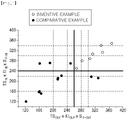
- FIG. 1 is a diagram illustrating a product of tensile strength, elongation, and fatigue strength of an outer wound portion and an inner wound portion of a wound coil according to an embodiment of the present invention.
- the present inventors investigated a crack distribution and durability changes in a shear plane according to characteristics of alloy components and microstructures for thick materials with different microstructures based on various alloy compositions, and as a result, derived Relational Expressions 1 to 4 to be described later.
- the present inventors confirmed that, by controlling a steel alloy composition range and controlling steel manufacturing process conditions to satisfy Relational Expressions 1 to 4, it is possible to manufacture high-strength thick composite-phase steel sheet having excellent material and durability uniformity and a tensile strength of 650 MPa or more, and having, as a base structure, a mixed phase of ferrite and bainite phases in which, in a microstructure in a center of a thickness of a steel sheet, an area fraction of each of a pearlite phase and a martensite and austenite (MA) phase is less than 5% and an area fraction of a martensite phase is less than 10%, and a product of tensile strength, elongation, and fatigue strength of an outer wound portion of a coil is 25 ⁇ 10 5 % or greater, and a product of tensile strength, elongation, and fatigue strength of an inner wound portion is 24 ⁇ 10 5 % or greater, and proposed the present invention.
- the thick composite-phase steel having excellent material and durability uniformity includes, by wt%, C: 0.05 to 0.15%, Si: 0.01 to 1.0%, Mn: 1.0 to 2.3%, Al: 0.01 to 0.1%, Cr: 0.005 to 1.0%, P: 0.001 to 0.05%, S: 0.001 to 0.01%, N: 0.001 to 0.01%, Nb: 0.005 to 0.07%, Ti: 0.005 to 0.11%, Fe, and inevitable impurities, and has a mixed phase of ferrite and bainite as a base structure, wherein, in the base structure, the area fraction of each of a pearlite phase and a martensite and austenite (MA) phase is less than 5%, and the area fraction of a martensite phase is less than 10%, and when a coil in a wound state is divided, in the lengthwise direction, into three parts: HEAD, MID, and TAIL parts, a product of tensile strength, elongation, and fatigue strength of an outer
- C is the most economical and effective element for reinforcing steel, and when the amount added increases, a precipitation strengthening effect or a bainite phase fraction increases, thereby increasing a tensile strength.
- the cooling rate in the center of the thickness during cooling after hot rolling is slow, so coarse carbide or pearlite is easy to form when the content of C is large.
- the content of C is preferably limited to 0.05 to 0.15%. More preferably, the content of C is limited to 0.06 to 0.12%.
- Si deoxidizes a molten steel and has a solid solution strengthening effect, and is advantageous in improving the formability by delaying the formation of the coarse carbide.
- the content is less than 0.01%, the solid solution strengthening effect is small and the effect of delaying the formation of carbide is small, so it is difficult to improve the formability, and when the content exceeds 1.0%, a red scale due to Si is formed on a surface of the steel sheet during the hot rolling, thereby not only reducing the quality of the surface of the steel sheet, but also reducing ductility and weldability. Therefore, in the present invention, it is preferable to limit the content of Si in the range of 0.01 to 1.0%, and more preferably 0.2 to 0.7%.
- Mn is an effective element for solid solution strengthening of steel, and increases hardenability of steel to facilitate the formation of the bainite phase during the cooling after hot rolling.
- the content of Mn is preferably limited to 1.0 to 2.3%. More preferably, the content of Mn is limited to the range of 1.1 to 2.0%.
- the content of Cr is preferably limited to 0.005 to 1.0%. More preferably, the content of Cr is limited to 0.3 to 0.9%.
- P has the effect of strengthening the solid solution and promoting the ferrite transformation at the same time.
- the content is less than 0.001%, it is economically disadvantageous because it requires a lot of manufacturing cost and it is insufficient to obtain strength, and when the content exceeds 0.05%, brittleness occurs due to grain boundary segregation, microcracks are easy to occur during forming, and the formability and durability greatly deteriorate. Therefore, it is preferable to control the content of P in the range of 0.001 to 0.05%.
- S is an impurity present in steel.
- S combines with Mn and the like to form non-metallic inclusions.
- the content is less than 0.001%, it takes a lot of time during a steelmaking operation, resulting in lowering productivity. Therefore, in the present invention, it is preferable to control the content of S in the range of 0.001 to 0.01%.
- Sol.Al is a component mainly added for deoxidation.
- the content is less than 0.01%, the effect of the addition is insufficient, and when the content exceeds 0.1%, the AlN combines with nitrogen to form AlN, so corner cracks are likely to occur in slab during the continuous casting, and defects are likely to occur due to the formation of inclusions. Therefore, in the present invention, it is preferable to control the content of S in the range of 0.01 to 0.1%.
- N is a representative solid solution strengthening element together with C, and forms coarse precipitates together with Ti, Al, and the like.
- the solid solution strengthening effect of N is superior to that of carbon, but there is a problem in that toughness is greatly reduced as the amount of N in steel increases.
- Ti is a representative precipitation strengthening element and forms coarse TiN in steel due to a strong affinity with N.
- TiN has the effect of suppressing a growth of grains during a heating process for hot rolling.
- Ti remaining after reacting with nitrogen is dissolved in steel and combined with carbon to form TiC precipitates, which is a useful component for improving the strength of the steel.
- Nb is a representative precipitation strengthening element together with Ti, and is precipitated during the hot rolling, and thus, effectively improves the strength and impact toughness of steel due to the effect of grain refinement by the delayed recrystallization.
- the content of Nb is less than 0.005%, the above effects may not be obtained, and when the content of Nb exceeds 0.06%, elongated grains are formed due to the excessive recrystallization delay during the hot rolling and the formability and durability deteriorate due to the formation of coarse composite precipitates. Therefore, in the present invention, it is preferable to limit the content of Nb in the range of 0.005 to 0.06%, and more preferably to control the content of Nb in the range of 0.01 to 0.06%.
- the remaining component of the present invention is iron (Fe).
- Fe iron
- unintended impurities may inevitably be mixed from a raw material or the surrounding environment, and thus, these impurities may not be excluded. Since these impurities are known to anyone of ordinary skill in the manufacturing process, all the contents are not specifically described in the present specification.
- the composite-phase steel has a mixed phase of ferrite and bainite as a base structure, and each of the ferrite and bainite may be included in less than 65 area%.
- the pearlite phase and the martensite and austenite (MA) phase in the base structure may be included in an area fraction of less than 5% respectively, and a martensite phase may be included in an area fraction of less than 10%.
- the product of the tensile strength, elongation, and fatigue strength of the outer wound portion of the coil, which is the region of the HEAD part and the TAIL part is 25 ⁇ 10 5 % or greater
- the product of the tensile strength, elongation, and fatigue strength of the inner wound portion of the coil, which is the region of the MID part is 24 ⁇ 10 5 % or greater.
- the manufacturing method of composite-phase steel according to the present invention includes: reheating a steel slab having the composition components as described above at a temperature of 1200 to 1350°C; manufacturing a hot-rolled steel sheet by finish hot rolling the reheated steel slab at a finish hot rolling temperature (FDT) satisfying the following [Relational Expression 1] of steel; primarily cooling the hot-rolled steel sheet to a mid-temperature (MT) range of 550 to 650°C to satisfy the following [Relational Expression 2]; and when the primarily cooled steel sheet is divided, in a lengthwise direction, into three parts: HEAD, MID, and TAIL parts, secondarily cooling a region of the HEAD part and the TAIL part corresponding to an outer wound portion of a coil during coiling to a temperature range from 450 to 550°C to satisfy the following [Relational Expression 3], and secondarily cooling a region of the MID part corresponding to an inner wound portion of the coil to the temperature range from 400 to 500°C to satisfy the following [Relation
- the steel slab having the above composition component is reheated at a temperature of 1200 to 1350°C.
- the reheating temperature is less than 1200°C, the precipitates are not sufficiently re-dissolved, so the formation of the precipitates in the process after the hot rolling decreases, and the coarse TiN remains.
- the reheating temperature exceeds 1350°C, the strength decreases due to abnormal grain growth of austenite grains, so the reheating temperature is preferably limited to 1200 to 1350°C.
- the hot-rolled steel sheet is manufactured by performing the finish hot rolling on the reheated steel slab at the finish hot rolling temperature (FDT) that satisfies the following [Relational Expression 1] of the steel.
- FDT finish hot rolling temperature
- Tn ⁇ 60 ⁇ FDT ⁇ Tn Tn 740 + 92 C ⁇ 80 Si + 70 Mn + 45 Cr + 650 Nb + 410 Ti ⁇ 1.4 t ⁇ 5
- the FDT of the above Relational Expression 1 is a finish hot-rolled temperature (°C)
- the recrystallization delay during the hot rolling promotes the ferrite phase transformation during the phase transformation, thereby contributing to the formation of fine and uniform grains in the center of the thickness and increasing the strength and durability.
- the untransformed phase decreases during the cooling, and the fraction of the coarse MA phase and martensite phase decreases and the coarse carbide or pearlite structure decreases in the center of the thickness where the cooling rate is relatively slow, so the non-uniform structure of the hot-rolled steel sheet is resolved.
- the microstructure of the steel is coarse and non-uniform, and the phase transformation is delayed to form the coarse MA phase and martensite phase, so fine cracks are excessively formed during the shear forming and punching forming, resulting in deteriorating the durability.
- the hot rolling preferably starts at a temperature in the range of 800 to 1000°C.
- the hot rolling starts at a temperature higher than 1000°C
- the temperature of the hot-rolled steel sheet increases, so the grain size becomes coarse and the quality of the surface of the hot-rolled steel sheet deteriorates.
- the hot rolling is performed at a temperature lower than 800°C
- the elongated grains are developed due to the excessive recrystallization delay, resulting in severe anisotropy and poor formability, and when the rolling is performed at a temperature equal to or lower than the austenite temperature range, the non-uniform microstructure may be developed more severely.
- the hot-rolled steel sheet is primarily cooled to a mid-temperature (MT) range of 550 to 650°C to satisfy the following [Relational Expression 2] .
- MT mid-temperature
- CR 1 min 210 ⁇ 850 C + 1.5 Si ⁇ 67.2 Mn ⁇ 59.6 Cr + 187 Ti + 852 Nb
- CR 1 max 240 ⁇ 850 C + 1.5 Si ⁇ 67.2 Mn ⁇ 59.6 Cr + 187 Ti + 852 Nb
- CR 1 of the above Relational Expression 2 is a primary cooling rate (°C/sec) in an FDT to MT (550 to 650°C) section, [C], [Si], [Mn], [Cr], [Ti], and [Nb] in the above Relational Expression 2 are wt% of the corresponding alloy element.
- the cooling rate in the center of the thickness is slower than at the position t/4 under the surface layer of the thickness of the rolled sheet, so the coarse ferrite is formed in the center of the thickness, and the non-uniform microstructure is formed.
- CR2 IN of the Relational Expression 4 is the secondary cooling rate (°C/sec) of the MT to coiling temperature section of the MID part, [C], [Si], [Mn], [Cr], [Ti], and [Nb] in the above Relational Expression 4 are wt% structure of the corresponding alloy element.
- the MID part of the hot-rolled sheet forming the inner wound portion of the coil after the coiling and the HEAD part and the TAIL part of the hot-rolled sheet forming the outer wound portion of the coil after the coiling have a large difference in heat recuperation and recooling behavior in the wound state.
- the MID part it is relatively easy to generate the MA phase, the carbide, and the pearlite phase, and the deterioration phenomenon of the conventional low-temperature phase is also caused, resulting in deteriorating the durability.
- the carbide is easier to form at the ferrite grain boundary than the bainite phase, and may be coarsely grown.
- the cooling rate is very slow, the pearlite phase is formed, which makes it easy to form cracks during the shear forming or punching forming, and to propagate cracks along grain boundaries even with a small external force.
- the region of the HEAD part and the TAIL part corresponding to the outer wound portion of the coil during the coiling is secondarily cooled to a temperature range from 450 to 550°C to satisfy the following [Relational Expression 3]
- the region of the MID part corresponding to the inner wound portion of the coil is secondarily cooled to the temperature range from 400 to 500°C to satisfy the following [Relational Expression 4].
- the wound coil may be air-cooled to a temperature ranging from room temperature to 200°C.
- the air cooling of the coil means cooling in the air at room temperature at a cooling rate of 0.001 to 10°C/hour.
- the cooling rate exceeds 10°C/hour, some untransformed phases in the steel are easily transformed into the MA phase, and thus, the shear formability, punching formability, and durability of the steel deteriorate, and in order to control the cooling rate to less than 0.001°C/hour, it is economically disadvantageous because separate heating and thermal insulation facilities are required.
- the method may further include pickling and oiling the coiled steel sheet after the secondary cooling.
- the method may further include heating the pickled or oiled steel sheet to a temperature range of 450 to 740°C, followed by hot-dip galvanizing.
- the hot-dip galvanizing may use a plating bath including 0.01 to 30% by weight of magnesium (Mg), 0.01 to 50% by weight of aluminum (Al), the remaining of Zn, and inevitable impurities.
- Mg magnesium
- Al aluminum
- the steel slab having the composition components shown in Table 1 was prepared. Then, the steel slab prepared as described above was hot-rolled, cooled and coiled under the conditions shown in Tables 2 and 3 to produce the coiled hot-rolled steel sheet. After the coiling, the cooling rate of the steel sheet was kept constant at 1°C/hour.
- Table 2 showed the thickness t of the hot-rolled steel sheet, a finish hot-rolling temperature (FDT), the mid-temperature (MT), a coiling temperature (CT), a cooling rate CR1 in a first section (FDT to MT) after hot rolling, and cooling rates CR2 OUT and CR2 IN in a second section (MT to CT), respectively.
- Table 3 showed the calculation results of the Relational Expressions 1 to 4, respectively.
- the microstructure of each hot-rolled steel sheet obtained as described above was measured by being divided into the inner wound portion and the outer wound portion of the coil, and the results were shown in Table 4 below.
- the steel microstructure is the result of analysis in the center of the thickness of the hot-rolled sheet, and the phase fractions of martensite (M), ferrite (F), bainite (B), and pearlite (P) were measured from the results of analysis at 3000 and 5000 magnifications using the scanning electron microscope (SEM).
- SEM scanning electron microscope
- the area fraction of the MA phase was analyzed using an optical microscope and an image analyzer after etching by the Repeller etching method, and is the result of analysis at 1000 magnification.
- the above mechanical properties are the results of testing the JIS No. 5 standard specimen by taking the specimen in a direction perpendicular to the rolling direction.
- a test piece with a gauge length part of 40 mm and a width of 20 mm was used as a bending fatigue test, and the result is the result of testing under the conditions of a stress ratio of -1 and a frequency of 15 Hz.
- Comparative Example 1 is a case in which the hot rolling temperature exceeds the range of Relational Expression 1 proposed in the present invention, and showed that the MA phase develops in the microstructure in the center and the area of the grain boundary becomes coarse, and as a result, microcracks are easily formed in the cross section when exposed to the fatigue environment, resulting in deteriorating the fatigue characteristics.
- Comparative Example 2 is a case where hot rolling temperature was less than the range of the above Relational Equation 1, the elongated grains were formed excessively in the center of the thickness due to hot rolling in a low temperature range, and as a result, the fatigue fracture occurs along weak grain boundaries. This is because the microcracks formed in the center of the thickness during the punching forming developed along the elongated ferrite grain boundary.
- Comparative Examples 3 and 4 are cases in which cooling conditions are not satisfied in the outer wound portion of the coil, that is, the HEAD part and the TAIL part of the hot-rolled sheet in the Relational Expression 3 proposed in the present invention. Specifically, Comparative Example 3 could confirm that, due to the relative rapid cooling control, as shown in Table 4, the martensite phase is excessively formed in the structure and the durability deteriorates due to the difference in hardness between the phases. Comparative Example 4 is a case of slow cooling control, and could confirm that it is difficult to secure sufficient bainite phase in the structure, and the pearlite phase fraction is high and the durability deteriorates.
- Comparative Examples 5 and 6 are cases in which the cooling condition of the inner wound portion of the coil, that is, the MID part of the hot-rolled sheet, is not satisfied in Relational Expression 3 proposed in the present invention, and the durability was not good due to a metallurgical phenomenon similar to that of Comparative Examples 3 and 4.
- Comparative Examples 7 and 12 showed steels that did not satisfy the component range of the present invention, and Comparative Example 7 showed a region in which the C content is excessively contained, and thus, the range of CR1 for securing an appropriate fraction of ferrite phase needs to be controlled to 31°C/sec or lower, but may not be controlled when considering the length of the rolling and cooling section of the actual facility. In addition, it was not easy to secure sufficient formability because the elongation decreased due to the formation of the excessive bainite phase in the structure.
- Comparative Example 8 is a case in which the C content was lower than the target, and showed that the low-temperature transformation phases such as bainite, including the martensite phase, were not sufficiently developed in the center of the thickness of the steel sheet, and a relatively coarse ferrite phase was formed, resulting in lowering the fatigue strength.
- the low-temperature transformation phases such as bainite, including the martensite phase
- Comparative Example 9 is a case in which the Si content is excessively high, and showed that the excessive MA phase is formed in the structure, and thus the harddenable property in a local area causes the difference in hardness between the phases and the surrounding base structure, thereby facilitating the occurrence of cracks in the fatigue environment and lowering the fatigue strength.
- excessive Si addition increases the probability of occurrence of red scale on the surface of the thick material, which is undesirable in terms of the use of wheel rim parts.
- Comparative Example 10 is a case in which the Mn content is excessively added, and showed that the martensite phase is developed excessively along the Mn segregation zone developed in the center of the thickness, and the shear and punching quality deteriorates, and thus, it is difficult to secure sufficient fatigue strength.
- Comparative Example 11 is a case in which the Mn content is added low, and could confirm that the composite-phase steel is prepared to satisfy Relational Expressions 1 to 4 for a recrystallization delay effect and a uniform microstructure, and both strength and fatigue strength are low because there are too few untransformed regions after ferrite phase transformation in the center of the thickness, result in making it difficult to secure a sufficient low-temperature transformation phase.
- Comparative Example 12 showed that the Cr content was excessively high, and similarly to Comparative Example 10, a lot of martensite phases formed locally in the center of the thickness were observed, and the fatigue characteristics deteriorate.
- FIG. 1 is a diagram illustrating a product of the tensile strength, elongation, and fatigue strength of the outer wound portion and the inner wound portion according to Inventive Examples and Comparative Examples of the present invention as described above.
- the case of Inventive Examples 1 to 7 of the present invention that satisfy the alloy composition and manufacturing process conditions of the present invention could confirm that the composite-phase steel with excellent material and durability uniformity may be obtained, in which the product of tensile strength, elongation, and fatigue strength of the outer wound portion is 25 ⁇ 10 5 % or greater, and the product of the tensile strength, elongation, and fatigue strength of the inner wound portion is 24 ⁇ 10 5 % or greater.
Landscapes
- Chemical & Material Sciences (AREA)
- Engineering & Computer Science (AREA)
- Organic Chemistry (AREA)
- Materials Engineering (AREA)
- Mechanical Engineering (AREA)
- Metallurgy (AREA)
- Physics & Mathematics (AREA)
- Thermal Sciences (AREA)
- Crystallography & Structural Chemistry (AREA)
- Chemical Kinetics & Catalysis (AREA)
- Heat Treatment Of Steel (AREA)
- Heat Treatment Of Sheet Steel (AREA)
- Coating With Molten Metal (AREA)
Abstract
Description
- The present invention mainly relates to manufacturing of a high-strength hot-rolled steel sheet having a thickness of 5 mm or more, used for members of a chassis part and a wheel rim of a commercial vehicle, and more particularly, to high-strength thick hot-rolled composite-phase steel in which a product of tensile strength × fatigue strength and elongation × fatigue strength of a steel sheet after punching forming is uniform in a lengthwise direction of a coil due to a tensile strength of 650 MPa or more and excellent cross-sectional quality during shear forming and punching forming, and a manufacturing method therefor.
- In order to secure high rigidity of members of chassis parts and wheel rims of commercial vehicles due to characteristics of the vehicles, the conventional high-strength hot-rolled steel sheet having a thickness of 5 mm or more and a tensile strength of 440 to 590 MPa has been used, but recently, a technology of using high-strength steel having a tensile strength of 650 MPa or more is being developed for weight reduction and high strength. In addition, in order to increase the weight reduction efficiency, parts are manufactured by being subjected to shear forming and multiple punching forming during the manufacturing of the parts within a range in which durability is secured, resulting in shortening a durability lifespan of parts with minute cracks formed in punched portions of a steel sheet during the shear and punching forming.
- In this regard, as the related art, a technology (Patent Documents 1 and 2) of using a ferrite phase as a matrix structure by coiling at a high temperature after performing typical hot rolling in austenite region and finely forming precipitates has been proposed. Also, a technology (Patent Document 3) of performing coiling after cooling a coiling temperature to a temperature at which a bainite phase is formed into a matrix structure so as not to form the coarse pearlite structure, etc., have been proposed. In addition, a technology (Patent Document 4) for refining austenite grains by applying a pressure of 40% or more in a non-recrystallization region during the hot rolling using Ti, Nb, etc., has also been proposed.
- However, alloy components such as Si, Mn, Al, Mo, and Cr, which are mainly used to manufacture such high-strength steels, are effective in improving the strength of the hot-rolled steel sheet, so it is necessary for thick products for commercial vehicles. However, when a lot of alloy components are added, since non-uniformity may be caused in a microstructure, during the shear or punching forming, microcracks that are easily generated in the punched portion are easily propagated to fatigue cracks in a fatigue environment, resulting in damage to parts. In particular, as a thickness of the steel sheet increases, a likelihood of a center in the thickness of the steel sheet being slowly cooled during manufacturing increases, so that non-uniformity of the structure further increases and the propagation speed of fatigue cracks also increases in the fatigue environment, resulting in deteriorating the durability.
- However, the above-described related art does not take into account fatigue properties of a high-strength thick material. In addition, it is effective to use precipitate-forming elements such as Ti, Nb, and V to refine grains of the thick material and obtain a precipitation strengthening effect. However, when the coiling is carried out at a high temperature of 500 to 700°C which is easy to form precipitates, or a cooling rate of the steel sheet is not controlled during the cooling after hot rolling, coarse carbides are formed in the center in a thickness of the thick material, so the quality of the shear surface quality deteriorates, and furthermore, applying a 40% pressure reduction in the non-recrystallization region during the hot rolling deteriorates the quality of the shape of the rolled sheet and increases a load on the equipment, making it difficult to apply in practice.
-
- (Patent Document 1)
Japanese Patent Laid-Open Publication No. 5-308808 - (Patent Document 2)
Japanese Patent Laid-Open Publication No. 5-279379 - (Patent Document 3)
Korea Patent No. 10-1528084 - (Patent Document 4)
Japanese Patent Laid-Open Publication No. 9-143570 - The present invention provides high-strength thick hot-rolled composite-phase steel in which a product of tensile strength × fatigue strength and elongation × fatigue strength of a steel sheet after punching forming is uniform in a lengthwise direction of a coil due to a tensile strength of 650 MPa or more and excellent cross-sectional quality during shear forming and punching forming, and a manufacturing method therefor.
- An object of the present invention is not limited to the above-described contents. The problems of the present invention will be understood from the overall content of this specification, and those of ordinary skill in the art to which the present invention pertains will have no difficulty in understanding additional problems of the present invention.
- According to an aspect of the present invention, composite-phase steel having excellent material and durability uniformity and a thickness of 5mm or more may include: by wt%, C: 0.05 to 0.15%, Si: 0.01 to 1.0%, Mn: 1.0 to 2.3%, Al: 0.01 to 0.1%, Cr: 0.005 to 1.0%, P: 0.001 to 0.05%, S: 0.001 to 0.01%, N: 0.001 to 0.01%, Nb: 0.005 to 0.07%, Ti: 0.005 to 0.11%, Fe, and inevitable impurities, and
- a mixed phase of ferrite and bainite as a base structure, wherein, in the base structure, an area fraction of each of a pearlite phase and a martensite and austenite (MA) phase is less than 5%, and an area fraction of a martensite phase is less than 10%, and
- when a coil in a wound state is divided, in a lengthwise direction, into three parts: HEAD, MID, and TAIL parts, a product of tensile strength, elongation, and fatigue strength of an outer wound portion of the coil, which is a region of the HEAD part and the TAIL part, is 25 × 105% or greater, and a product of tensile strength, elongation, and fatigue strength of an inner wound portion of the coil, which is a region of the MID part, is 24 × 105% or greater.
- The area fraction of the ferrite and the bainite may be less than 65%, respectively.
- The composite-phase steel may be a pickled and oiled (PO) steel sheet.
- The composite-phase steel may be a hot-dip galvanized steel sheet having a hot-dip galvanized layer formed on at least one surface thereof.
- According to an aspect of the present invention,
- a manufacturing method of composite-phase steel having excellent material and durability uniformity and a thickness of 5mm or more may include: reheating a steel slab including, by wt%, C:0.05 to 0.15%, Si:0.01 to 1.0%, Mn:1.0 to 2.3%, Al:0.01 to 0.1%, Cr:0.005 to 1.0%, P:0.001 to 0.05%, S:0.001 to 0.01%, N:0.001 to 0.01%, Nb:0.005 to 0.07%, Ti 0.005 to 0.11%, Fe and unavoidable impurities at a temperature of 1200 to 1350°C;
- manufacturing a hot-rolled steel sheet by finish hot rolling the reheated steel slab at a finish hot rolling temperature (FDT) satisfying the following [Relational Expression 1] of steel;
- primarily cooling the hot-rolled steel sheet to a mid-temperature (MT) range of 550 to 650°C to satisfy the following [Relational Expression 2]; and
- when the primarily cooled steel sheet is divided, in a lengthwise direction, into three parts: HEAD, MID, and TAIL parts, secondarily cooling a region of the HEAD part and the TAIL part corresponding to an outer wound portion of a coil during coiling to a temperature range from 450 to 550°C to satisfy the following [Relational Expression 3], and secondarily cooling a region of the MID part corresponding to an inner wound portion of the coil during coiling to a temperature range from 400 to 500°C to satisfy the following [Relational Expression 4], and then coiling the cooled region of the MID part;

- the FDT of the above Relational Expression 1 is a finish hot-rolling temperature (°C),
- [C], [Si], [Mn], [Cr], [Nb], and [Ti] in the above Relational Expression 1 are wt% of the corresponding alloy element,
- t of the above Relational Expression 1 is a thickness of a final hot-rolled sheet (mm)
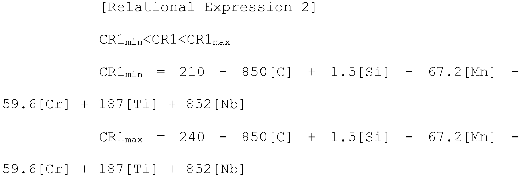
- CR1 of the above Relational Expression 2 is a primary cooling rate (°C/sec) in an FDT to MT (550 to 650°C) section,
- [C], [Si], [Mn], [Cr], [Ti], and [Nb] in the above Relational Expression 2 are wt% of the corresponding alloy element

- CR2OUT of the above Relational Expression 3 is the secondary cooling rate (°C/sec) in MT to coiling temperature section of the HEAD part and the TAIL part,
- [C], [Si], [Mn], [Cr], [Ti], and [Nb] in the above Relational Expression 3 are wt% of the corresponding alloy element

- CR2IN of the above Relational Expression 4 is the secondary cooling rate (°C/sec) in MT to coiling temperature section of the MID part,
- [C], [Si], [Mn], [Cr], [Ti], and [Nb] in the above Relational Expression 4 are wt% structure of the corresponding alloy element.
- The composite-phase steel may have a mixed phase of ferrite and bainite as a base structure, in the base structure, an area fraction of each of a pearlite phase and a martensite and austenite (MA) phase may be less than 5%, and an area fraction of a martensite phase may be less than 10%, and a product of tensile strength, elongation, and fatigue strength of the outer wound portion of the coil, which is the region of the HEAD part and the TAIL part, may be 25 × 105% or greater, and a product of tensile strength, elongation, and fatigue strength of the inner wound portion of the coil, which is the region of the MID part, may be 24 × 105% or greater.
- The manufacturing method may further include pickling and oiling the coiled steel sheet after the secondary cooling.
- The manufacturing method may further include heating the pickled or oiled steel sheet to a temperature range from 450 to 740°C, and then hot-dip galvanizing the steel sheet.
- The hot-dip galvanizing may be formed using a plating bath including, by wt%, magnesium (Mg): 0.01 to 30%, Al: 0.01 to 50%, the remaining of Zn, and inevitable impurities.
- According to the present invention of the above configuration, it is possible to effectively provide a high-strength thick composite-phase steel sheet having excellent material and durability uniformity and a tensile strength of 650 MPa or more, and having, as a base structure, a mixed phase of ferrite and bainite phases each having an area fraction of less than 65%, in which, in a microstructure in a center of a thickness, an area fraction of each of a pearlite phase and a martensite and austenite (MA) phase is less than 5% and an area fraction of a martensite phase is less than 10%, and a product of tensile strength, elongation, and fatigue strength of an outer wound portion is 25 × 105% or greater, and a product of tensile strength, elongation, and fatigue strength of an inner wound portion is 24 × 105% or greater.
-
FIG. 1 is a diagram illustrating a product of tensile strength, elongation, and fatigue strength of an outer wound portion and an inner wound portion of a wound coil according to an embodiment of the present invention. - Hereinafter, the present invention will be described.
- In order to solve the problems of the related art described above, the present inventors investigated a crack distribution and durability changes in a shear plane according to characteristics of alloy components and microstructures for thick materials with different microstructures based on various alloy compositions, and as a result, derived Relational Expressions 1 to 4 to be described later. That is, the present inventors confirmed that, by controlling a steel alloy composition range and controlling steel manufacturing process conditions to satisfy Relational Expressions 1 to 4, it is possible to manufacture high-strength thick composite-phase steel sheet having excellent material and durability uniformity and a tensile strength of 650 MPa or more, and having, as a base structure, a mixed phase of ferrite and bainite phases in which, in a microstructure in a center of a thickness of a steel sheet, an area fraction of each of a pearlite phase and a martensite and austenite (MA) phase is less than 5% and an area fraction of a martensite phase is less than 10%, and a product of tensile strength, elongation, and fatigue strength of an outer wound portion of a coil is 25 × 105% or greater, and a product of tensile strength, elongation, and fatigue strength of an inner wound portion is 24 × 105% or greater, and proposed the present invention.
- The thick composite-phase steel having excellent material and durability uniformity includes, by wt%, C: 0.05 to 0.15%, Si: 0.01 to 1.0%, Mn: 1.0 to 2.3%, Al: 0.01 to 0.1%, Cr: 0.005 to 1.0%, P: 0.001 to 0.05%, S: 0.001 to 0.01%, N: 0.001 to 0.01%, Nb: 0.005 to 0.07%, Ti: 0.005 to 0.11%, Fe, and inevitable impurities, and has a mixed phase of ferrite and bainite as a base structure, wherein, in the base structure, the area fraction of each of a pearlite phase and a martensite and austenite (MA) phase is less than 5%, and the area fraction of a martensite phase is less than 10%, and when a coil in a wound state is divided, in the lengthwise direction, into three parts: HEAD, MID, and TAIL parts, a product of tensile strength, elongation, and fatigue strength of an outer wound portion of the coil, which is a region of the HEAD part and the TAIL part, is 25 × 105% or greater, and a product tensile strength, elongation, and fatigue strength of an inner wound portion of the coil, which is a region of the MID part, is 24 × 105% or greater.
- Hereinafter, the alloy composition components and the reasons for limiting the content of the present invention will be described. Meanwhile, in the following steel alloy components, "%" means "weight" unless otherwise specified.
- ·C: 0.05 to 0.15%
- C is the most economical and effective element for reinforcing steel, and when the amount added increases, a precipitation strengthening effect or a bainite phase fraction increases, thereby increasing a tensile strength. In addition, when the thickness of the hot-rolled steel sheet increases, the cooling rate in the center of the thickness during cooling after hot rolling is slow, so coarse carbide or pearlite is easy to form when the content of C is large. Therefore, when the content is less than 0.05%, it is difficult to obtain a sufficient reinforcing effect, and when the content exceeds 0.15%, there is a problem in that the shear formability deteriorates and the durability deteriorates due to the formation of the pearlite phase or coarse carbide in the center of the thickness, and the weldability also deteriorates. Therefore, in the present invention, the content of C is preferably limited to 0.05 to 0.15%. More preferably, the content of C is limited to 0.06 to 0.12%.
- ·Si: 0.01 to 1.0 %
- Si deoxidizes a molten steel and has a solid solution strengthening effect, and is advantageous in improving the formability by delaying the formation of the coarse carbide. However, there is a problem that, when the content is less than 0.01%, the solid solution strengthening effect is small and the effect of delaying the formation of carbide is small, so it is difficult to improve the formability, and when the content exceeds 1.0%, a red scale due to Si is formed on a surface of the steel sheet during the hot rolling, thereby not only reducing the quality of the surface of the steel sheet, but also reducing ductility and weldability. Therefore, in the present invention, it is preferable to limit the content of Si in the range of 0.01 to 1.0%, and more preferably 0.2 to 0.7%.
- ·Mn: 1.0 to 2.3%
- Like Si, Mn is an effective element for solid solution strengthening of steel, and increases hardenability of steel to facilitate the formation of the bainite phase during the cooling after hot rolling. However, when the content is less than 1.0%, the above effects may not be obtained due to the addition, and when the content exceeds 2.3%, the hardenability greatly increases, so the martensite phase transformation is easy to occur, and a segregation portion is greatly developed in the center of the thickness when casting the slab in the casting process, and during the cooling after hot rolling, the microstructure in the thickness direction is formed non-uniformly, resulting in deteriorating the shear formability and durability. Therefore, in the present invention, the content of Mn is preferably limited to 1.0 to 2.3%. More preferably, the content of Mn is limited to the range of 1.1 to 2.0%.
- ·Cr: 0.005 to 1.0%,
- Cr solid-solution strengthens the steel and delays the ferrite phase transformation upon cooling, thereby helping to form the bainite at the coiling temperature. However, when the content is less than 0.005%, the above effects may not be obtained according to the addition, and when the content exceeds 1.0%, the ferrite transformation is excessively delayed, and thus, the elongation deteriorates due to the formation of the martensite phase. In addition, similar to Mn, the segregation portion in the center of the thickness is greatly developed, and the microstructure in the thickness direction is non-uniform, resulting in deteriorating the shear formability and durability. Therefore, in the present invention, the content of Cr is preferably limited to 0.005 to 1.0%. More preferably, the content of Cr is limited to 0.3 to 0.9%.
- ·P: 0.001 to 0.05%
- Like Si, P has the effect of strengthening the solid solution and promoting the ferrite transformation at the same time. However, when the content is less than 0.001%, it is economically disadvantageous because it requires a lot of manufacturing cost and it is insufficient to obtain strength, and when the content exceeds 0.05%, brittleness occurs due to grain boundary segregation, microcracks are easy to occur during forming, and the formability and durability greatly deteriorate. Therefore, it is preferable to control the content of P in the range of 0.001 to 0.05%.
- ·S: 0.001 to 0.01%
- S is an impurity present in steel. When the content exceeds 0.01%, S combines with Mn and the like to form non-metallic inclusions. As a result, there is a problem in that it is easy to cause microcracks during cutting of steel and greatly reduces the shear formability and durability. On the other hand, when the content is less than 0.001%, it takes a lot of time during a steelmaking operation, resulting in lowering productivity. Therefore, in the present invention, it is preferable to control the content of S in the range of 0.001 to 0.01%.
- ·Sol.Al: 0.01 to 0.1%,
- Sol.Al is a component mainly added for deoxidation. When the content is less than 0.01%, the effect of the addition is insufficient, and when the content exceeds 0.1%, the AlN combines with nitrogen to form AlN, so corner cracks are likely to occur in slab during the continuous casting, and defects are likely to occur due to the formation of inclusions. Therefore, in the present invention, it is preferable to control the content of S in the range of 0.01 to 0.1%.
- ·N: 0.001 to 0.01%
- N is a representative solid solution strengthening element together with C, and forms coarse precipitates together with Ti, Al, and the like. In general, the solid solution strengthening effect of N is superior to that of carbon, but there is a problem in that toughness is greatly reduced as the amount of N in steel increases. In addition, in order to prepare the steel to have N of less than 0.001%, it takes a lot of time during the steelmaking operation, resulting in lowering productivity. Therefore, in the present invention, it is preferable to control the content of N in the range of 0.001 to 0.01%.
- ·Ti: 0.005 to 0.11%
- Ti is a representative precipitation strengthening element and forms coarse TiN in steel due to a strong affinity with N. TiN has the effect of suppressing a growth of grains during a heating process for hot rolling. In addition, Ti remaining after reacting with nitrogen is dissolved in steel and combined with carbon to form TiC precipitates, which is a useful component for improving the strength of the steel. However, when the content of Ti is less than 0.005%, the above effects may not be obtained, and when the content of Ti content exceeds 0.11%, there is a problem in that collision resistance properties during forming deteriorate due to the generation of coarse TiN and the coarsening of the precipitates. Therefore, in the present invention, it is preferable to limit the content of Ti in the range of 0.005 to 0.11%, and more preferably to control the content of Ti in the range of 0.01 to 0.1%.
- ·Nb: 0.005 to 0.06%
- Nb is a representative precipitation strengthening element together with Ti, and is precipitated during the hot rolling, and thus, effectively improves the strength and impact toughness of steel due to the effect of grain refinement by the delayed recrystallization. However, when the content of Nb is less than 0.005%, the above effects may not be obtained, and when the content of Nb exceeds 0.06%, elongated grains are formed due to the excessive recrystallization delay during the hot rolling and the formability and durability deteriorate due to the formation of coarse composite precipitates. Therefore, in the present invention, it is preferable to limit the content of Nb in the range of 0.005 to 0.06%, and more preferably to control the content of Nb in the range of 0.01 to 0.06%.
- The remaining component of the present invention is iron (Fe). However, in a general manufacturing process, unintended impurities may inevitably be mixed from a raw material or the surrounding environment, and thus, these impurities may not be excluded. Since these impurities are known to anyone of ordinary skill in the manufacturing process, all the contents are not specifically described in the present specification.
- Meanwhile, in the present invention, the composite-phase steel has a mixed phase of ferrite and bainite as a base structure, and each of the ferrite and bainite may be included in less than 65 area%.
- In addition, the pearlite phase and the martensite and austenite (MA) phase in the base structure may be included in an area fraction of less than 5% respectively, and a martensite phase may be included in an area fraction of less than 10%.
- When the area fraction of the pearlite phase and martensite and austenite (MA) phase is 5% or more, respectively, there is a problem in that the local strain difference due to the difference in hardness between the base structure and other phases facilitates the occurrence of cracks due to stress concentration during deformation, resulting in deteriorating the fatigue properties.
- In addition, when the area fraction of the martensite phase is 10% or more, there is a problem in that, as the fractions of the low-temperature ferrite phase and the bainite phase decrease, the occurrence of cracks during fatigue as described above is facilitated, and the elongation deteriorates.
- Furthermore, in the composite-phase steel according to the present invention, when the coil in the wound state is divided, in the lengthwise direction, into three parts: HEAD, MID, and TAIL parts, the product of the tensile strength, elongation, and fatigue strength of the outer wound portion of the coil, which is the region of the HEAD part and the TAIL part, is 25 × 105% or greater, and the product of the tensile strength, elongation, and fatigue strength of the inner wound portion of the coil, which is the region of the MID part, is 24 × 105% or greater.
- Next, the manufacturing method of the thick composite-phase steel of the present invention will be described in detail.
- The manufacturing method of composite-phase steel according to the present invention includes: reheating a steel slab having the composition components as described above at a temperature of 1200 to 1350°C; manufacturing a hot-rolled steel sheet by finish hot rolling the reheated steel slab at a finish hot rolling temperature (FDT) satisfying the following [Relational Expression 1] of steel; primarily cooling the hot-rolled steel sheet to a mid-temperature (MT) range of 550 to 650°C to satisfy the following [Relational Expression 2]; and when the primarily cooled steel sheet is divided, in a lengthwise direction, into three parts: HEAD, MID, and TAIL parts, secondarily cooling a region of the HEAD part and the TAIL part corresponding to an outer wound portion of a coil during coiling to a temperature range from 450 to 550°C to satisfy the following [Relational Expression 3], and secondarily cooling a region of the MID part corresponding to an inner wound portion of the coil to the temperature range from 400 to 500°C to satisfy the following [Relational Expression 4], and then coiling the cooled region of the MID part.
- First, in the present invention, the steel slab having the above composition component is reheated at a temperature of 1200 to 1350°C. In this case, when the reheating temperature is less than 1200°C, the precipitates are not sufficiently re-dissolved, so the formation of the precipitates in the process after the hot rolling decreases, and the coarse TiN remains. When the reheating temperature exceeds 1350°C, the strength decreases due to abnormal grain growth of austenite grains, so the reheating temperature is preferably limited to 1200 to 1350°C.
- Next, in the present invention, the hot-rolled steel sheet is manufactured by performing the finish hot rolling on the reheated steel slab at the finish hot rolling temperature (FDT) that satisfies the following [Relational Expression 1] of the steel.

the FDT of the above Relational Expression 1 is a finish hot-rolled temperature (°C), - [C], [Si], [Mn], [Cr], [Nb], and [Ti] in the above Relational Expression 1 are wt% of the corresponding alloy element,
- t of the above Relational Expression 1 is a thickness of a final hot-rolled sheet (mm)
- The recrystallization delay during the hot rolling promotes the ferrite phase transformation during the phase transformation, thereby contributing to the formation of fine and uniform grains in the center of the thickness and increasing the strength and durability. In addition, due to the promotion of the ferrite phase transformation, the untransformed phase decreases during the cooling, and the fraction of the coarse MA phase and martensite phase decreases and the coarse carbide or pearlite structure decreases in the center of the thickness where the cooling rate is relatively slow, so the non-uniform structure of the hot-rolled steel sheet is resolved.
- However, it is difficult to make the microstructure uniform in the center of the thickness of a thick material having a thickness of 5 mm or more, and when the hot rolling is performed at an excessively low temperature in order to obtain the effect of the recrystallization delay in the center of the thickness, the deformed structure is developed strongly at a t/4 position just below a surface layer of the rolled sheet thickness, and thus, the non-uniformity of the microstructure with the center of the thickness increases, so the microcracks are likely to occur in the non-uniform portion during the shear deformation or punching deformation, and the durability of the parts also deteriorates. Therefore, as shown in the above Relational Expression 1, the above effect may be obtained only when the hot rolling is completed at Tn temperature and Tn-60 which are the temperature at which the recrystallization delay starts to be suitable for the thick material.
- If the rolling ends at a temperature higher than the temperature range suggested in the above Relational Expression 1, the microstructure of the steel is coarse and non-uniform, and the phase transformation is delayed to form the coarse MA phase and martensite phase, so fine cracks are excessively formed during the shear forming and punching forming, resulting in deteriorating the durability. On the other hand, when the rolling ends at a temperature lower than the temperature range presented in the above Relational Expression 1, in the thick high-strength steel having a thickness of more than 5 mm, a fine ferrite phase fraction increases but the elongated grain shape is formed at a position t/4 of a thickness just under a surface layer where the temperature is relatively low due to the ferrite phase transformation promotion, which may be a factor that rapidly propagates cracks, and the non-uniform microstructure may remain in the center of the thickness, which may adversely affect the durability.
- Meanwhile, the hot rolling preferably starts at a temperature in the range of 800 to 1000°C. When the hot rolling starts at a temperature higher than 1000°C, the temperature of the hot-rolled steel sheet increases, so the grain size becomes coarse and the quality of the surface of the hot-rolled steel sheet deteriorates. On the other hand, when the hot rolling is performed at a temperature lower than 800°C, the elongated grains are developed due to the excessive recrystallization delay, resulting in severe anisotropy and poor formability, and when the rolling is performed at a temperature equal to or lower than the austenite temperature range, the non-uniform microstructure may be developed more severely.
- In the present invention, the hot-rolled steel sheet is primarily cooled to a mid-temperature (MT) range of 550 to 650°C to satisfy the following [Relational Expression 2] .

- CR1 of the above Relational Expression 2 is a primary cooling rate (°C/sec) in an FDT to MT (550 to 650°C) section,
[C], [Si], [Mn], [Cr], [Ti], and [Nb] in the above Relational Expression 2 are wt% of the corresponding alloy element. - As the temperature range from immediately after the hot rolling to a specific MT in the range of 550 to 650°, which is the first section, when the thickness of the rolled sheet exceeds 5 mm due to the temperature range where the ferrite phase transformation occurs during cooling, the cooling rate in the center of the thickness is slower than at the position t/4 under the surface layer of the thickness of the rolled sheet, so the coarse ferrite is formed in the center of the thickness, and the non-uniform microstructure is formed.
- Therefore, immediately after the hot rolling, in the (FDT to MT) temperature region of the above Relational Expression 2, it is required to control the cooling rate to a specific cooling rate (CR1min) or higher so that the ferrite phase transformation in the center of the thickness does not proceed excessively. However, it is necessary to limit the cooling rate to CR1max or less because it is difficult to secure an appropriate fraction of the ferrite phase during excessive quenching, and the elongation deteriorates.
- Next, in the present invention, when the primarily cooled steel sheet is divided, in a lengthwise direction, into three parts: HEAD, MID, and TAIL parts, a region of the HEAD part and the TAIL part corresponding to the outer wound portion of a coil during coiling is secondarily cooled to a temperature range from 450 to 550°C to satisfy the following [Relational Expression 3], and a region of the MID part corresponding to the inner wound portion of the coil is secondarily cooled to the temperature range from 400 to 500°C to satisfy the following [Relational Expression 4], and then coiled;

- CR2OUT of the above Relational Expression 3 is the secondary cooling rate (°C/sec) in MT to coiling temperature section of the HEAD part and the TAIL part,
[C], [Si], [Mn], [Cr], [Ti], and [Nb] in the above Relational Expression 3 are wt% of the corresponding alloy element
- CR2IN of the Relational Expression 4 is the secondary cooling rate (°C/sec) of the MT to coiling temperature section of the MID part,
[C], [Si], [Mn], [Cr], [Ti], and [Nb] in the above Relational Expression 4 are wt% structure of the corresponding alloy element. - In the second section temperature range from the MT to the coiling temperature (CT), it is necessary to suppress the excessive formation of the MA phase, the carbide, the pearlite phase, and the martensite phase. However, in the case of thick material, the MID part of the hot-rolled sheet forming the inner wound portion of the coil after the coiling and the HEAD part and the TAIL part of the hot-rolled sheet forming the outer wound portion of the coil after the coiling have a large difference in heat recuperation and recooling behavior in the wound state. In particular, in the case of the MID part, it is relatively easy to generate the MA phase, the carbide, and the pearlite phase, and the deterioration phenomenon of the conventional low-temperature phase is also caused, resulting in deteriorating the durability.
- Therefore, in the present invention, for the cooling rate CR2OUT of the second section for the HEAD part and the TAIL part of the hot-rolled sheet forming the outer wound portion of the coil after the coiling, and the cooling rate CR2IN of the second section for the MID part of the hot-rolled sheet forming the inner wound portion of the coil after the coiling, respectively, there is a need to performing the cooling to satisfy the set Relational Expressions 3 and 4 in consideration of the steel component.
- Described in detail, when the cooling rate of both the inner/outer wound portions of the coil are slower than the specific cooling rates CR2O-min and CR2I-min respectively shown in each Relational Expression, the carbide is easier to form at the ferrite grain boundary than the bainite phase, and may be coarsely grown. In addition, when the cooling rate is very slow, the pearlite phase is formed, which makes it easy to form cracks during the shear forming or punching forming, and to propagate cracks along grain boundaries even with a small external force. On the other hand, when the cooling rate is faster than the specific cooling rate CR2O-max and CR2I-max shown in each Relational Expression, the MA phase or the martensite phase, which causes the hardness difference between the phases, is excessively formed, so it is easy to secure strength, but the elongation or durability deteriorate.
- Taking this into consideration, in the present invention, when the primarily cooled steel sheet is divided, in the lengthwise direction, into the three parts: HEAD, MID, and TAIL parts, the region of the HEAD part and the TAIL part corresponding to the outer wound portion of the coil during the coiling is secondarily cooled to a temperature range from 450 to 550°C to satisfy the following [Relational Expression 3], and the region of the MID part corresponding to the inner wound portion of the coil is secondarily cooled to the temperature range from 400 to 500°C to satisfy the following [Relational Expression 4].
- Thereafter, in the present invention, the wound coil may be air-cooled to a temperature ranging from room temperature to 200°C. The air cooling of the coil means cooling in the air at room temperature at a cooling rate of 0.001 to 10°C/hour. In this case, when the cooling rate exceeds 10°C/hour, some untransformed phases in the steel are easily transformed into the MA phase, and thus, the shear formability, punching formability, and durability of the steel deteriorate, and in order to control the cooling rate to less than 0.001°C/hour, it is economically disadvantageous because separate heating and thermal insulation facilities are required. Preferably, it is preferable to perform cooling at 0.01 to 1°C/hour.
- Alternatively, in the present invention, the method may further include pickling and oiling the coiled steel sheet after the secondary cooling.
- The method may further include heating the pickled or oiled steel sheet to a temperature range of 450 to 740°C, followed by hot-dip galvanizing.
- In the present invention, the hot-dip galvanizing may use a plating bath including 0.01 to 30% by weight of magnesium (Mg), 0.01 to 50% by weight of aluminum (Al), the remaining of Zn, and inevitable impurities.
- Hereinafter, the present invention will be described in more detail through Inventive Examples.
-
[Table 1] Steel Type C Si Mn Cr Al P S N Ti Nb 1 0.06 0.9 1.5 0.22 0.03 0.01 0.004 0.004 0.05 0.025 2 0.06 0.9 1.5 0.25 0.03 0.01 0.005 0.004 0.05 0.005 3 0.07 0.9 1.4 0.21 0.03 0.01 0.004 0.005 0.04 0.033 4 0.07 0.9 1.3 0.19 0.03 0.01 0.004 0.005 0.04 0.033 5 0.07 0.4 1.5 0.83 0.05 0.01 0.003 0.006 0.04 0.045 6 0.07 0.4 1.5 0.83 0.05 0.01 0.003 0.006 0.04 0.045 7 0.16 0.5 1.5 0.22 0.03 0.01 0.003 0.004 0.07 0.032 8 0.04 0.5 1.5 0.31 0.03 0.01 0.002 0.004 0.07 0.032 9 0.08 1.2 1.7 0.35 0.03 0.01 0.003 0.004 0.06 0.025 10 0.07 0.5 2.5 0.22 0.03 0.01 0.003 0.004 0.07 0.034 11 0.08 0.5 0.8 0.36 0.03 0.01 0.003 0.004 0.05 0.035 12 0.06 0.5 1.7 1.1 0.03 0.01 0.004 0.004 0.05 0.035 13 0.06 0.1 1.7 0.35 0.03 0.01 0.003 0.005 0.09 0.032 14 0.06 0.3 1.3 0.55 0.03 0.01 0.003 0.005 0.04 0.043 15 0.07 0.5 1.5 0.51 0.03 0.01 0.003 0.005 0.06 0.051 16 0.08 0.3 1.6 0.53 0.03 0.01 0.003 0.005 0.07 0.063 17 0.09 0.3 1.6 0.71 0.03 0.01 0.002 0.004 0.09 0.045 18 0.09 0.1 1.5 0.81 0.03 0.01 0.003 0.004 0.09 0.045 19 0.11 0.5 1.5 0.72 0.03 0.01 0.003 0.004 0.09 0.055 - * In Table 1, units of alloy components are wt%, and the remaining components are Fe and inevitable impurities.
[Table 2] Steel Type Division Thickness (mm) FDT (°C) CR1 (°C/sec) MT (°C) CR2OUT (°C/sec) CR2IN (°C/sec) CTou T (°C) CTI N (°C) 1 Comparative Example 1 11 900 80 600 45 70 465 442 2 Comparative Example 2 11 780 58 550 28 53 466 443 3 Comparative Example 3 9 840 60 600 90 62 330 441 4 Comparative Example 4 9 840 60 600 15 62 580 444 5 Comparative Example 5 9 850 63 600 40 80 480 360 6 Comparative Example 6 9 850 63 600 40 25 480 525 7 Comparative Example 7 6 850 50 650 54 70 488 402 8 Comparative Example 8 8 850 85 550 19 62 492 452 9 Comparative Example 9 8 820 55 600 57 62 429 422 10 Comparative Example 10 8 880 50 650 64 73 458 410 11 Comparative Example 11 8 800 85 550 12 54 513 456 12 Comparative Example 12 8 880 58 650 64 70 457 429 13 Inventive Example 1 8 880 85 600 30 69 511 440 14 Inventive Example 2 7 850 85 550 15 63 505 450 15 Inventive Example 3 9 870 80 600 39 68 482 436 16 Inventive Example 4 8 890 80 600 36 72 491 429 17 Inventive Example 5 9 880 60 630 48 71 485 423 18 Inventive Example 6 10 890 65 630 43 72 500 427 19 Inventive Example 7 11 860 58 630 53 70 471 414 -
[Table 3] Steel Type Division Relational Expression 1 Relational Expression 2 Relational Expression 3 Relational Expression 4 Tn CR1min CR1max CR2O-min CR2O-max CR2I-min CR2I-max 1 Comparative Example 1 817 77 107 22 57 39 75 2 Comparative Example 2 805 58 88 21 56 39 74 3 Comparative Example 3 814 81 111 21 55 37 75 4 Comparative Example 4 806 89 119 20 52 35 73 5 Comparative Example 5 897 47 77 18 48 31 78 6 Comparative Example 6 897 47 77 18 48 31 78 7 Comparative Example 7 878 1 31 17 44 28 94 8 Comparative Example 8 868 98 128 16 41 26 70 9 Comparative Example 9 823 41 71 31 82 57 84 10 Comparative Example 10 938 12 42 24 64 43 90 11 Comparative Example 11 819 107 137 10 26 15 67 12 Comparative Example 12 913 19 49 24 63 43 81 13 Inventive Example 1 926 68 98 11 30 16 75 14 Inventive Example 2 879 83 113 12 31 19 71 15 Inventive Example 3 887 75 105 18 48 30 78 16 Inventive Example 4 925 70 100 16 44 26 81 17 Inventive Example 5 929 39 69 18 48 29 84 18 Inventive Example 6 941 40 70 14 38 21 82 19 Inventive Example 7 912 37 67 22 58 36 88 - The steel slab having the composition components shown in Table 1 was prepared. Then, the steel slab prepared as described above was hot-rolled, cooled and coiled under the conditions shown in Tables 2 and 3 to produce the coiled hot-rolled steel sheet. After the coiling, the cooling rate of the steel sheet was kept constant at 1°C/hour.
- Table 2 showed the thickness t of the hot-rolled steel sheet, a finish hot-rolling temperature (FDT), the mid-temperature (MT), a coiling temperature (CT), a cooling rate CR1 in a first section (FDT to MT) after hot rolling, and cooling rates CR2OUT and CR2IN in a second section (MT to CT), respectively. Table 3 showed the calculation results of the Relational Expressions 1 to 4, respectively.
- The microstructure of each hot-rolled steel sheet obtained as described above was measured by being divided into the inner wound portion and the outer wound portion of the coil, and the results were shown in Table 4 below. The steel microstructure is the result of analysis in the center of the thickness of the hot-rolled sheet, and the phase fractions of martensite (M), ferrite (F), bainite (B), and pearlite (P) were measured from the results of analysis at 3000 and 5000 magnifications using the scanning electron microscope (SEM). The area fraction of the MA phase was analyzed using an optical microscope and an image analyzer after etching by the Repeller etching method, and is the result of analysis at 1000 magnification.
- In addition, for each hot-rolled steel sheet obtained as described above, mechanical properties were measured and durability was evaluated, and the results are shown in Table 5 below. In Table 5 below, YS, TS, YR, T-El, and SF mean 0.2% off-set yield strength, tensile strength, yield ratio, fracture elongation, and fatigue strength, and "O" and "I" meaning OUT and IN, were added to each item to divide the result values for the inner and outer wound parts.
- Meanwhile, the above mechanical properties are the results of testing the JIS No. 5 standard specimen by taking the specimen in a direction perpendicular to the rolling direction. The evaluation result of the durability was obtained by punching a hole with a diameter of 10 mm in the center of the test piece under the condition of a clearance of 12% as a reference fatigue strength value of Nf = 105. For the test piece, a test piece with a gauge length part of 40 mm and a width of 20 mm was used as a bending fatigue test, and the result is the result of testing under the conditions of a stress ratio of -1 and a frequency of 15 Hz.
[Table 4] Division Structure of outer wound portion of hot-rolled coil Structure of inner wound portion of hot-rolled coil F B M MA P F B M MA P Comparative Example 1 65 28 2 5 0 65 27 2 6 0 Comparative Example 2 78 16 1 4 1 80 14 1 4 1 Comparative Example 3 62 15 20 3 0 72 25 2 1 0 Comparative Example 4 76 15 0 3 6 73 24 2 1 0 Comparative Example 5 73 24 2 1 0 63 16 19 2 0 Comparative Example 6 73 25 1 1 0 77 14 0 5 4 Comparative Example 7 28 70 1 1 0 20 75 4 1 0 Comparative Example 8 78 15 0 1 6 80 13 0 1 6 Comparative Example 9 68 23 1 6 2 70 21 1 6 2 Comparative Example 10 23 65 11 1 0 21 67 11 1 0 Comparative Example 11 79 15 0 1 5 75 18 1 1 5 Comparative Example 12 21 77 1 1 0 20 78 1 1 0 Inventive Example 1 59 37 2 2 0 67 30 2 1 0 Inventive Example 2 59 38 2 1 0 64 33 2 1 0 Inventive Example 3 52 45 2 1 0 57 39 2 2 0 Inventive Example 4 54 42 3 1 0 60 35 2 2 1 Inventive Example 5 40 55 3 1 1 45 50 2 2 1 Inventive Example 6 34 60 3 2 1 41 52 3 3 1 Inventive Example 7 28 65 4 2 1 31 60 4 3 2 - * In Table 4, F represents ferrite, B represents bainite, M represents martensite, and P represents pearlite.
[Table 5] Division Physical property of outer wound portion of hot-rolled coil Physical property of inner wound portion of hot-rolled coil YSo (MPa) TSo (MPa) YRO Elo (% ) SF-O (MPa) YSI (MPa) TSI (MPa) YRI ElI (%) SF-I (MPa) Comparative Example 1 472 583 0.81 27 105 435 551 0.79 27 102 Comparative Example 2 439 556 0.79 27 107 445 549 0.81 27 108 Comparative Example 3 538 690 0.78 24 115 550 679 0.81 25 160 Comparative Example 4 502 652 0.77 24 103 549 678 0.81 25 159 Comparative Example 5 638 778 0.82 25 159 615 788 0.78 24 115 Comparative Example 6 633 781 0.81 26 162 608 750 0.81 25 113 Comparative Example 7 856 1031 0.83 11 220 920 1109 0.83 11 221 Comparative Example 8 401 489 0.82 30 83 396 483 0.82 31 80 Comparative Example 9 562 711 0.79 24 125 590 719 0.82 24 122 Comparative Example 10 640 790 0.81 24 118 649 801 0.81 24 115 Comparative Example 11 457 557 0.82 26 110 466 561 0.83 26 108 Comparative Example 12 681 830 0.82 15 171 681 821 0.83 15 169 Inventive Example 1 554 675 0.82 25 158 543 662 0.82 25 151 Inventive Example 2 552 681 0.81 25 166 558 680 0.82 26 158 Inventive Example 3 612 756 0.81 23 180 608 751 0.81 24 170 Inventive Example 4 622 749 0.83 23 177 608 741 0.82 23 169 Inventive Example 5 739 935 0.79 19 207 727 920 0.79 19 199 Inventive Example 6 713 914 0.78 18 205 718 909 0.79 19 197 Inventive Example 7 745 955 0.78 17 210 747 945 0.79 17 195 - As shown in Tables 1 to 5, it could be seen that all of Inventive Examples 1 to 7 satisfying the manufacturing conditions including the component range and the above Relational Expressions 1 to 4 proposed in the present invention uniformly secure the target material and durability.
- On the other hand, Comparative Example 1 is a case in which the hot rolling temperature exceeds the range of Relational Expression 1 proposed in the present invention, and showed that the MA phase develops in the microstructure in the center and the area of the grain boundary becomes coarse, and as a result, microcracks are easily formed in the cross section when exposed to the fatigue environment, resulting in deteriorating the fatigue characteristics.
- Comparative Example 2 is a case where hot rolling temperature was less than the range of the above Relational Equation 1, the elongated grains were formed excessively in the center of the thickness due to hot rolling in a low temperature range, and as a result, the fatigue fracture occurs along weak grain boundaries. This is because the microcracks formed in the center of the thickness during the punching forming developed along the elongated ferrite grain boundary.
- Comparative Examples 3 and 4 are cases in which cooling conditions are not satisfied in the outer wound portion of the coil, that is, the HEAD part and the TAIL part of the hot-rolled sheet in the Relational Expression 3 proposed in the present invention. Specifically, Comparative Example 3 could confirm that, due to the relative rapid cooling control, as shown in Table 4, the martensite phase is excessively formed in the structure and the durability deteriorates due to the difference in hardness between the phases. Comparative Example 4 is a case of slow cooling control, and could confirm that it is difficult to secure sufficient bainite phase in the structure, and the pearlite phase fraction is high and the durability deteriorates.
- Comparative Examples 5 and 6 are cases in which the cooling condition of the inner wound portion of the coil, that is, the MID part of the hot-rolled sheet, is not satisfied in Relational Expression 3 proposed in the present invention, and the durability was not good due to a metallurgical phenomenon similar to that of Comparative Examples 3 and 4.
- On the other hand, Comparative Examples 7 and 12 showed steels that did not satisfy the component range of the present invention, and Comparative Example 7 showed a region in which the C content is excessively contained, and thus, the range of CR1 for securing an appropriate fraction of ferrite phase needs to be controlled to 31°C/sec or lower, but may not be controlled when considering the length of the rolling and cooling section of the actual facility. In addition, it was not easy to secure sufficient formability because the elongation decreased due to the formation of the excessive bainite phase in the structure.
- Comparative Example 8 is a case in which the C content was lower than the target, and showed that the low-temperature transformation phases such as bainite, including the martensite phase, were not sufficiently developed in the center of the thickness of the steel sheet, and a relatively coarse ferrite phase was formed, resulting in lowering the fatigue strength.
- Comparative Example 9 is a case in which the Si content is excessively high, and showed that the excessive MA phase is formed in the structure, and thus the harddenable property in a local area causes the difference in hardness between the phases and the surrounding base structure, thereby facilitating the occurrence of cracks in the fatigue environment and lowering the fatigue strength. In addition, excessive Si addition increases the probability of occurrence of red scale on the surface of the thick material, which is undesirable in terms of the use of wheel rim parts.
- Comparative Example 10 is a case in which the Mn content is excessively added, and showed that the martensite phase is developed excessively along the Mn segregation zone developed in the center of the thickness, and the shear and punching quality deteriorates, and thus, it is difficult to secure sufficient fatigue strength.
- Comparative Example 11 is a case in which the Mn content is added low, and could confirm that the composite-phase steel is prepared to satisfy Relational Expressions 1 to 4 for a recrystallization delay effect and a uniform microstructure, and both strength and fatigue strength are low because there are too few untransformed regions after ferrite phase transformation in the center of the thickness, result in making it difficult to secure a sufficient low-temperature transformation phase.
- Comparative Example 12 showed that the Cr content was excessively high, and similarly to Comparative Example 10, a lot of martensite phases formed locally in the center of the thickness were observed, and the fatigue characteristics deteriorate.
-
FIG. 1 is a diagram illustrating a product of the tensile strength, elongation, and fatigue strength of the outer wound portion and the inner wound portion according to Inventive Examples and Comparative Examples of the present invention as described above. As illustrated inFIG. 1 , the case of Inventive Examples 1 to 7 of the present invention that satisfy the alloy composition and manufacturing process conditions of the present invention could confirm that the composite-phase steel with excellent material and durability uniformity may be obtained, in which the product of tensile strength, elongation, and fatigue strength of the outer wound portion is 25 × 105% or greater, and the product of the tensile strength, elongation, and fatigue strength of the inner wound portion is 24 × 105% or greater. - The present invention is not limited to the above implementation examples and examples, but may be manufactured in a variety of different forms, and those of ordinary skill in the art to which the present invention pertains will understand that the present invention may be implemented in other specific forms without changing the technical spirit or essential features of the present invention. Therefore, it is to be understood that the implementation examples and examples described above are illustrative rather than being restrictive in all aspects.
Claims (10)
- Composite-phase steel having excellent material and durability uniformity and a thickness of 5mm or more, the composite-phase steel comprising:by wt%, C: 0.05 to 0.15%, Si: 0.01 to 1.0%, Mn: 1.0 to 2.3%, Al: 0.01 to 0.1%, Cr: 0.005 to 1.0%, P: 0.001 to 0.05%, S: 0.001 to 0.01%, N: 0.001 to 0.01%, Nb: 0.005 to 0.07%, Ti: 0.005 to 0.11%, Fe, and inevitable impurities, anda mixed phase of ferrite and bainite as a base structure, wherein, in the base structure, an area fraction of each of a pearlite phase and a martensite and austenite (MA) phase is less than 5%, and an area fraction of a martensite phase is less than 10%, andwhen a coil in a wound state is divided, in a lengthwise direction, into three parts: HEAD, MID, and TAIL parts, a product of tensile strength, elongation, and fatigue strength of an outer wound portion of the coil, which is a region of the HEAD part and the TAIL part, is 25 × 105% or greater, and a product of tensile strength, elongation, and fatigue strength of an inner wound portion of the coil, which is a region of the MID part, is 24 × 105% or greater.
- The composite-phase steel of claim 1, wherein the area fraction of the ferrite and the bainite is less than 65%, respectively.
- The composite-phase steel of claim 1, wherein the composite-phase steel is a pickled and oiled (PO) steel sheet.
- The composite-phase steel of claim 1, wherein the composite-phase steel is a hot-dip galvanized steel sheet having a hot-dip galvanized layer formed on at least one surface thereof.
- A manufacturing method of composite-phase steel having excellent material and durability uniformity and a thickness of 5mm or more, the manufacturing method comprising:reheating a steel slab including, by wt%, C:0.05 to 0.15%, Si:0.01 to 1.0%, Mn:1.0 to 2.3%, Al:0.01 to 0.1%, Cr:0.005 to 1.0%, P:0.001 to 0.05%, S:0.001 to 0.01%, N:0.001 to 0.01%, Nb:0.005 to 0.07%, Ti 0.005 to 0.11%, Fe and unavoidable impurities at a temperature of 1200 to 1350°C;manufacturing a hot-rolled steel sheet by finish hot rolling the reheated steel slab at a finish hot rolling (FDT) satisfying the following [Relational Expression 1] of steel;primarily cooling the hot-rolled steel sheet to a mid-temperature (MT) range of 550 to 650°C to satisfy the following [Relational Expression 2]; andwhen the primarily cooled steel sheet is divided, in a lengthwise direction, into three parts: HEAD, MID, and TAIL parts, secondarily cooling a region of the HEAD part and the TAIL part corresponding to an outer wound portion of a coil during winding to a temperature range from 450 to 550°C to satisfy the following [Relational Expression 3], and secondarily cooling a region of the MID part corresponding to an inner wound portion of the coil to the temperature range from 400 to 500°C to satisfy the following [Relational Expression 4], and then coiling the secondly cooled steel sheet;
 the FDT of the above Relational Expression 1 is a finish hot-rolling temperature (°C),[C], [Si], [Mn], [Cr], [Nb], and [Ti] in the above Relational Expression 1 are wt% of the corresponding alloy element,t of the above Relational Expression 1 is a thickness of a final hot-rolled sheet (mm)
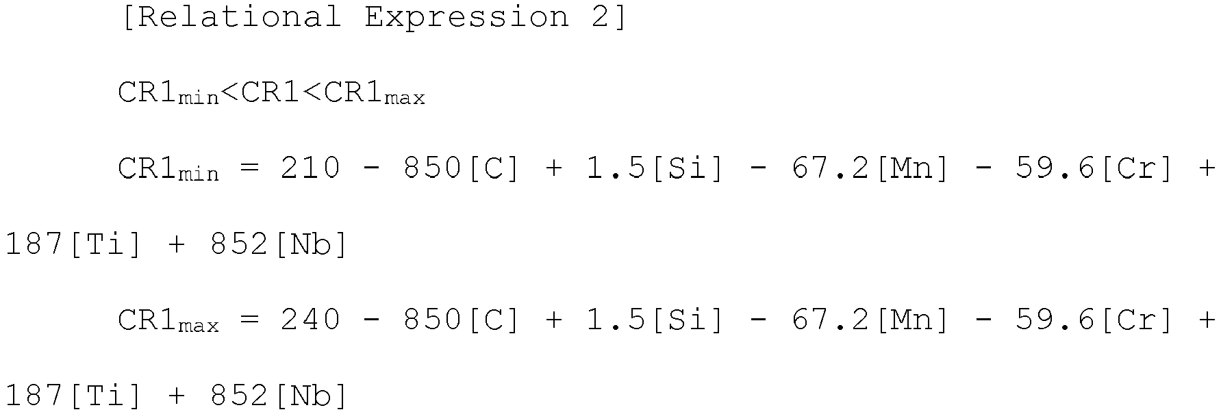 CR1 of the above Relational Expression 2 is a primary cooling rate (°C/sec) in an FDT to MT (550 to 650°C) section,[C], [Si], [Mn], [Cr], [Ti], and [Nb] in the above Relational Expression 2 are wt% of the corresponding alloy element
 CR2OUT of the above Relational Expression 3 is the secondary cooling rate (°C/sec) in MT to coiling temperature section of the HEAD part and the TAIL part,[C], [Si], [Mn], [Cr], [Ti], and [Nb] in the above Relational Expression 3 are wt% of the corresponding alloy element
 CR2IN of the above Relational Expression 4 is the secondary cooling rate (°C/sec) in MT to coiling temperature section of the MID part,[C], [Si], [Mn], [Cr], [Ti], and [Nb] in the above Relational Expression 4 are wt% structure of the corresponding alloy element.
 - The manufacturing method of claim 5, wherein the composite-phase steel has a mixed phase of ferrite and bainite as a base structure, in the base structure, an area fraction of each of a pearlite phase and a martensite and austenite (MA) phase is less than 5%, and an area fraction of a martensite phase is less than 10%, and a product of tensile strength, elongation, and fatigue strength of the outer wound portion of the coil, which is the region of the HEAD part and the TAIL part, is 25 × 105% or greater, and a product of tensile strength, elongation, and fatigue strength of the inner wound portion of the coil, which is the region of the MID part, is 24 × 105% or greater.
- The manufacturing method of claim 5, wherein the wound steel sheet is air-cooled to a temperature range from room temperature to 200°C.
- The manufacturing method of claim 5, further comprising pickling and oiling the coiled steel sheet after the secondary cooling.
- The manufacturing method of claim 8, further comprising heating the pickled or oiled steel sheet to a temperature range from 450 to 740°C, and then hot-dip galvanizing the steel sheet.
- The manufacturing method of claim 9, wherein the hot-dip galvanizing is formed using a plating bath including, by wt%, magnesium (Mg): 0.01 to 30%, Al: 0.01 to 50%, the remaining of Zn, and inevitable impurities.
Applications Claiming Priority (2)
| Application Number | Priority Date | Filing Date | Title |
|---|---|---|---|
| KR1020190158289A KR102307928B1 (en) | 2019-12-02 | 2019-12-02 | High strength multiphase steel sheet with excellent durability and manufacturing method thereof |
| PCT/KR2020/016925 WO2021112488A1 (en) | 2019-12-02 | 2020-11-26 | Thick composite-phase steel having excellent durability and manufacturing method therefor |
Publications (2)
| Publication Number | Publication Date |
|---|---|
| EP4071262A1 true EP4071262A1 (en) | 2022-10-12 |
| EP4071262A4 EP4071262A4 (en) | 2022-12-28 |
Family
ID=76221008
Family Applications (1)
| Application Number | Title | Priority Date | Filing Date |
|---|---|---|---|
| EP20896577.2A Pending EP4071262A4 (en) | 2019-12-02 | 2020-11-26 | THICK COMPOSITE STEEL WITH EXCELLENT DURABILITY AND ITS MANUFACTURING PROCESS |
Country Status (6)
| Country | Link |
|---|---|
| US (2) | US12435400B2 (en) |
| EP (1) | EP4071262A4 (en) |
| JP (1) | JP7431325B2 (en) |
| KR (1) | KR102307928B1 (en) |
| CN (1) | CN114641587B (en) |
| WO (1) | WO2021112488A1 (en) |
Cited By (1)
| Publication number | Priority date | Publication date | Assignee | Title |
|---|---|---|---|---|
| EP4636118A4 (en) * | 2022-12-12 | 2026-04-01 | Posco Co Ltd | STEEL SHEET AND METHOD FOR PRODUCTION OF IT |
Families Citing this family (2)
| Publication number | Priority date | Publication date | Assignee | Title |
|---|---|---|---|---|
| KR20230072050A (en) | 2021-11-17 | 2023-05-24 | 주식회사 포스코 | High strength steel plate having excellent impact toughness after cold forming and high yield ratio and method for manufacturing the same |
| CN117265380B (en) * | 2022-06-15 | 2026-01-20 | 宝山钢铁股份有限公司 | 800 MPa-level high-reaming hot-dip galvanized steel plate and manufacturing method thereof |
Family Cites Families (26)
| Publication number | Priority date | Publication date | Assignee | Title |
|---|---|---|---|---|
| JP3042738B2 (en) | 1992-03-31 | 2000-05-22 | 雪印乳業株式会社 | Ganglioside GM3 composition and method for producing the same |
| JPH05308808A (en) | 1992-05-13 | 1993-11-22 | Mitsubishi Agricult Mach Co Ltd | Apparatus for detecting angular velocity of mobile farm machine |
| JPH08143952A (en) * | 1994-11-21 | 1996-06-04 | Sumitomo Metal Ind Ltd | Method for producing high-strength hot-rolled steel sheet with excellent workability, fatigue characteristics and surface properties |
| JP3477955B2 (en) | 1995-11-17 | 2003-12-10 | Jfeスチール株式会社 | Method for producing high-strength hot-rolled steel sheet having ultrafine structure |
| JP3885314B2 (en) | 1997-09-29 | 2007-02-21 | Jfeスチール株式会社 | Method for producing high-strength hot-rolled steel sheet having excellent shape and workability |
| JP3767132B2 (en) | 1997-11-11 | 2006-04-19 | Jfeスチール株式会社 | Method for producing high-strength hot-rolled steel sheet having high ductility and excellent material uniformity |
| JPH11310852A (en) | 1998-02-26 | 1999-11-09 | Nippon Steel Corp | High-strength hot-rolled steel sheet with extremely excellent fatigue properties and method for producing the same |
| KR100368831B1 (en) | 1998-12-29 | 2003-03-17 | 주식회사 포스코 | Manufacturing method of high strength hot rolled steel sheet with tensile strength of 70 kg / square millimeter |
| KR100340580B1 (en) | 1999-12-27 | 2002-06-12 | 이구택 | A TENSILE STRENGTH OF 780MPa GRDE HOT ROLLED STEEL SHEET FOR AUTOMOBILE AND A METHOD FOR MANUFACTURING IT |
| KR100723200B1 (en) | 2005-12-16 | 2007-05-29 | 주식회사 포스코 | Method for manufacturing high strength hot rolled steel sheet with excellent balance in elongation-elongation and elongation flange-fatigue |
| EP2392682B1 (en) | 2009-01-30 | 2019-09-11 | JFE Steel Corporation | Thick high-tensile-strength hot-rolled steel sheet with excellent low-temperature toughness and process for production of same |
| JP5195469B2 (en) | 2009-01-30 | 2013-05-08 | Jfeスチール株式会社 | Manufacturing method for thick-walled high-tensile hot-rolled steel sheet with excellent low-temperature toughness |
| JP5724267B2 (en) | 2010-09-17 | 2015-05-27 | Jfeスチール株式会社 | High-strength hot-rolled steel sheet excellent in punching workability and manufacturing method thereof |
| KR101536422B1 (en) | 2013-10-10 | 2015-07-13 | 주식회사 포스코 | High strength hot-rolled steel having excellent bending formability and method for manufacturing the same |
| KR101568519B1 (en) * | 2013-12-24 | 2015-11-11 | 주식회사 포스코 | Hot rolled steel sheet having excellent deformation anisotropy in sheared edge and anti fatigue property and method for manufacturing the same |
| KR20150075541A (en) * | 2013-12-26 | 2015-07-06 | 주식회사 포스코 | High strength hot rolled steel sheet have excellent formability and fatigue resistance And Method of manufacturing the same |
| JP6149778B2 (en) | 2014-03-31 | 2017-06-21 | Jfeスチール株式会社 | Steel plate with excellent wear resistance and method for producing the same |
| JP6191769B2 (en) | 2014-05-28 | 2017-09-06 | 新日鐵住金株式会社 | Hot rolled steel sheet and manufacturing method thereof |
| JP6252499B2 (en) | 2015-01-13 | 2017-12-27 | Jfeスチール株式会社 | Manufacturing method of hot-rolled steel strip, cold-rolled steel strip and hot-rolled steel strip |
| JP6202012B2 (en) | 2015-02-03 | 2017-09-27 | Jfeスチール株式会社 | Manufacturing method of high-strength steel sheet with excellent formability |
| KR101758485B1 (en) | 2015-12-15 | 2017-07-17 | 주식회사 포스코 | High strength hot-dip galvanized steel sheet having excellent surface quality and spot weldability, and method for manufacturing the same |
| JP2018016873A (en) * | 2016-07-29 | 2018-02-01 | 株式会社神戸製鋼所 | High strength and high processability cold-rolled steel sheet coil with small variation of strength in coil and manufacturing method thereof |
| BR112019000766B8 (en) | 2016-08-05 | 2023-03-14 | Nippon Steel & Sumitomo Metal Corp | STEEL SHEET |
| KR101797383B1 (en) * | 2016-08-09 | 2017-11-13 | 주식회사 포스코 | High strength hot rolled steel sheet having low deviation of mechanical property and excellent surface quality and method for manufacturing the same |
| US11136643B2 (en) | 2016-08-10 | 2021-10-05 | Jfe Steel Corporation | High-strength steel sheet and method for producing same |
| KR101988765B1 (en) | 2017-12-21 | 2019-06-12 | 주식회사 포스코 | Hot rolled steel sheet with excellent durability and method for manufacturing thereof |
-
2019
- 2019-12-02 KR KR1020190158289A patent/KR102307928B1/en active Active
-
2020
- 2020-11-26 CN CN202080077393.XA patent/CN114641587B/en active Active
- 2020-11-26 US US17/779,096 patent/US12435400B2/en active Active
- 2020-11-26 WO PCT/KR2020/016925 patent/WO2021112488A1/en not_active Ceased
- 2020-11-26 JP JP2022532567A patent/JP7431325B2/en active Active
- 2020-11-26 EP EP20896577.2A patent/EP4071262A4/en active Pending
-
2025
- 2025-10-03 US US19/349,944 patent/US20260028706A1/en active Pending
Cited By (1)
| Publication number | Priority date | Publication date | Assignee | Title |
|---|---|---|---|---|
| EP4636118A4 (en) * | 2022-12-12 | 2026-04-01 | Posco Co Ltd | STEEL SHEET AND METHOD FOR PRODUCTION OF IT |
Also Published As
| Publication number | Publication date |
|---|---|
| US20220403489A1 (en) | 2022-12-22 |
| JP2023504150A (en) | 2023-02-01 |
| US12435400B2 (en) | 2025-10-07 |
| CN114641587B (en) | 2023-08-25 |
| KR20210068808A (en) | 2021-06-10 |
| US20260028706A1 (en) | 2026-01-29 |
| CN114641587A (en) | 2022-06-17 |
| EP4071262A4 (en) | 2022-12-28 |
| KR102307928B1 (en) | 2021-09-30 |
| JP7431325B2 (en) | 2024-02-14 |
| WO2021112488A1 (en) | 2021-06-10 |
Similar Documents
| Publication | Publication Date | Title |
|---|---|---|
| EP2053139B1 (en) | Hot-rolled steel sheets excellent both in workability and in strength and toughness after heat treatment and process for production thereof | |
| US20260028706A1 (en) | Thick composite-phase steel having excellent durability and manufacturing method therefor | |
| EP2653582A1 (en) | Hot-dip zinc-plated steel sheet and process for production thereof | |
| JP2005126733A (en) | Steel sheet for hot pressing and automotive parts with excellent high-temperature workability | |
| US20240337003A1 (en) | High-strength steel having high yield ratio and excellent durability, and method for manufacturing same | |
| CN113166893B (en) | High-strength steel material having excellent durability and method for producing same | |
| CN113840934A (en) | High-strength member, method for producing high-strength member, and method for producing steel sheet for high-strength member | |
| CN116615570B (en) | High-strength thick hot-rolled steel plate with excellent elongation and method for producing the same | |
| CN115461482B (en) | Steel sheet, component, and method for manufacturing same | |
| EP3822383B1 (en) | Hot rolled coated steel sheet having high strength, high formability, excellent bake hardenability and method of manufacturing same | |
| EP3964600A1 (en) | Ultra-high strength steel sheet having excellent shear workability and method for manufacturing same | |
| CN108350550B (en) | High-strength cold-rolled steel sheet having excellent shear workability and method for producing same | |
| EP3730652B1 (en) | Ultrahigh strength cold-rolled steel sheet and manufacturing method thereof | |
| JPH10251794A (en) | Hot rolled steel plate for structural purpose, excellent in press formability and surface characteristic, and its production | |
| EP4234747A1 (en) | High-strength steel plate having excellent workability, and method for manufacturing same | |
| EP4234743A1 (en) | High-strength steel sheet having excellent thermal stability, and method for manufacturing same | |
| CN117616144A (en) | Cold rolled steel plate and manufacturing method thereof | |
| KR102307927B1 (en) | High strength dp steel sheet of which the durability and flexibility are outstanding and a production metfod therefor | |
| EP4640883A1 (en) | Cold-rolled steel sheet and manufacturing method therefor | |
| EP4435135A1 (en) | High-yield ratio high-strength steel plate having excellent impact resistance after cold forming and manufacturing method therefor | |
| EP4640884A1 (en) | Cold rolled steel sheet and method for manufacturing same | |
| KR20230043353A (en) | High strength cold rolled steel sheet having excellent surface quality and low mechanical property deviation and manufacturing method of the same |
Legal Events
| Date | Code | Title | Description |
|---|---|---|---|
| STAA | Information on the status of an ep patent application or granted ep patent |
Free format text: STATUS: THE INTERNATIONAL PUBLICATION HAS BEEN MADE |
|
| PUAI | Public reference made under article 153(3) epc to a published international application that has entered the european phase |
Free format text: ORIGINAL CODE: 0009012 |
|
| STAA | Information on the status of an ep patent application or granted ep patent |
Free format text: STATUS: REQUEST FOR EXAMINATION WAS MADE |
|
| 17P | Request for examination filed |
Effective date: 20220628 |
|
| AK | Designated contracting states |
Kind code of ref document: A1 Designated state(s): AL AT BE BG CH CY CZ DE DK EE ES FI FR GB GR HR HU IE IS IT LI LT LU LV MC MK MT NL NO PL PT RO RS SE SI SK SM TR |
|
| REG | Reference to a national code |
Ref country code: DE Ref legal event code: R079 Free format text: PREVIOUS MAIN CLASS: C22C0038380000 Ipc: C21D0001020000 |
|
| A4 | Supplementary search report drawn up and despatched |
Effective date: 20221128 |
|
| RAP3 | Party data changed (applicant data changed or rights of an application transferred) |
Owner name: POSCO |
|
| RIC1 | Information provided on ipc code assigned before grant |
Ipc: C23C 30/00 20060101ALI20221122BHEP Ipc: C23C 2/12 20060101ALI20221122BHEP Ipc: C23C 2/02 20060101ALI20221122BHEP Ipc: C23C 2/06 20060101ALI20221122BHEP Ipc: C22C 38/38 20060101ALI20221122BHEP Ipc: C22C 38/28 20060101ALI20221122BHEP Ipc: C22C 38/26 20060101ALI20221122BHEP Ipc: C22C 38/04 20060101ALI20221122BHEP Ipc: C22C 38/02 20060101ALI20221122BHEP Ipc: C21D 9/46 20060101ALI20221122BHEP Ipc: C21D 8/02 20060101ALI20221122BHEP Ipc: C21D 1/02 20060101AFI20221122BHEP |
|
| DAV | Request for validation of the european patent (deleted) | ||
| DAX | Request for extension of the european patent (deleted) |