EP4071218A1 - Method for producing non-sintered liquid metal ink - Google Patents
Method for producing non-sintered liquid metal ink Download PDFInfo
- Publication number
- EP4071218A1 EP4071218A1 EP21876738.2A EP21876738A EP4071218A1 EP 4071218 A1 EP4071218 A1 EP 4071218A1 EP 21876738 A EP21876738 A EP 21876738A EP 4071218 A1 EP4071218 A1 EP 4071218A1
- Authority
- EP
- European Patent Office
- Prior art keywords
- liquid metal
- ink
- ethanol
- oxide film
- manufacturing
- Prior art date
- Legal status (The legal status is an assumption and is not a legal conclusion. Google has not performed a legal analysis and makes no representation as to the accuracy of the status listed.)
- Pending
Links
Images



Classifications
-
- C—CHEMISTRY; METALLURGY
- C09—DYES; PAINTS; POLISHES; NATURAL RESINS; ADHESIVES; COMPOSITIONS NOT OTHERWISE PROVIDED FOR; APPLICATIONS OF MATERIALS NOT OTHERWISE PROVIDED FOR
- C09D—COATING COMPOSITIONS, e.g. PAINTS, VARNISHES OR LACQUERS; FILLING PASTES; CHEMICAL PAINT OR INK REMOVERS; INKS; CORRECTING FLUIDS; WOODSTAINS; PASTES OR SOLIDS FOR COLOURING OR PRINTING; USE OF MATERIALS THEREFOR
- C09D11/00—Inks
- C09D11/52—Electrically conductive inks
-
- B—PERFORMING OPERATIONS; TRANSPORTING
- B22—CASTING; POWDER METALLURGY
- B22F—WORKING METALLIC POWDER; MANUFACTURE OF ARTICLES FROM METALLIC POWDER; MAKING METALLIC POWDER; APPARATUS OR DEVICES SPECIALLY ADAPTED FOR METALLIC POWDER
- B22F1/00—Metallic powder; Treatment of metallic powder, e.g. to facilitate working or to improve properties
- B22F1/05—Metallic powder characterised by the size or surface area of the particles
- B22F1/054—Nanosized particles
-
- B—PERFORMING OPERATIONS; TRANSPORTING
- B22—CASTING; POWDER METALLURGY
- B22F—WORKING METALLIC POWDER; MANUFACTURE OF ARTICLES FROM METALLIC POWDER; MAKING METALLIC POWDER; APPARATUS OR DEVICES SPECIALLY ADAPTED FOR METALLIC POWDER
- B22F9/00—Making metallic powder or suspensions thereof
- B22F9/02—Making metallic powder or suspensions thereof using physical processes
- B22F9/06—Making metallic powder or suspensions thereof using physical processes starting from liquid material
- B22F9/08—Making metallic powder or suspensions thereof using physical processes starting from liquid material by casting, e.g. through sieves or in water, by atomising or spraying
-
- C—CHEMISTRY; METALLURGY
- C09—DYES; PAINTS; POLISHES; NATURAL RESINS; ADHESIVES; COMPOSITIONS NOT OTHERWISE PROVIDED FOR; APPLICATIONS OF MATERIALS NOT OTHERWISE PROVIDED FOR
- C09D—COATING COMPOSITIONS, e.g. PAINTS, VARNISHES OR LACQUERS; FILLING PASTES; CHEMICAL PAINT OR INK REMOVERS; INKS; CORRECTING FLUIDS; WOODSTAINS; PASTES OR SOLIDS FOR COLOURING OR PRINTING; USE OF MATERIALS THEREFOR
- C09D11/00—Inks
- C09D11/02—Printing inks
- C09D11/03—Printing inks characterised by features other than the chemical nature of the binder
- C09D11/033—Printing inks characterised by features other than the chemical nature of the binder characterised by the solvent
-
- C—CHEMISTRY; METALLURGY
- C09—DYES; PAINTS; POLISHES; NATURAL RESINS; ADHESIVES; COMPOSITIONS NOT OTHERWISE PROVIDED FOR; APPLICATIONS OF MATERIALS NOT OTHERWISE PROVIDED FOR
- C09D—COATING COMPOSITIONS, e.g. PAINTS, VARNISHES OR LACQUERS; FILLING PASTES; CHEMICAL PAINT OR INK REMOVERS; INKS; CORRECTING FLUIDS; WOODSTAINS; PASTES OR SOLIDS FOR COLOURING OR PRINTING; USE OF MATERIALS THEREFOR
- C09D11/00—Inks
- C09D11/02—Printing inks
- C09D11/03—Printing inks characterised by features other than the chemical nature of the binder
- C09D11/037—Printing inks characterised by features other than the chemical nature of the binder characterised by the pigment
-
- C—CHEMISTRY; METALLURGY
- C09—DYES; PAINTS; POLISHES; NATURAL RESINS; ADHESIVES; COMPOSITIONS NOT OTHERWISE PROVIDED FOR; APPLICATIONS OF MATERIALS NOT OTHERWISE PROVIDED FOR
- C09D—COATING COMPOSITIONS, e.g. PAINTS, VARNISHES OR LACQUERS; FILLING PASTES; CHEMICAL PAINT OR INK REMOVERS; INKS; CORRECTING FLUIDS; WOODSTAINS; PASTES OR SOLIDS FOR COLOURING OR PRINTING; USE OF MATERIALS THEREFOR
- C09D11/00—Inks
- C09D11/02—Printing inks
- C09D11/10—Printing inks based on artificial resins
- C09D11/106—Printing inks based on artificial resins containing macromolecular compounds obtained by reactions only involving carbon-to-carbon unsaturated bonds
-
- C—CHEMISTRY; METALLURGY
- C09—DYES; PAINTS; POLISHES; NATURAL RESINS; ADHESIVES; COMPOSITIONS NOT OTHERWISE PROVIDED FOR; APPLICATIONS OF MATERIALS NOT OTHERWISE PROVIDED FOR
- C09D—COATING COMPOSITIONS, e.g. PAINTS, VARNISHES OR LACQUERS; FILLING PASTES; CHEMICAL PAINT OR INK REMOVERS; INKS; CORRECTING FLUIDS; WOODSTAINS; PASTES OR SOLIDS FOR COLOURING OR PRINTING; USE OF MATERIALS THEREFOR
- C09D7/00—Features of coating compositions, not provided for in group C09D5/00; Processes for incorporating ingredients in coating compositions
- C09D7/80—Processes for incorporating ingredients
-
- B—PERFORMING OPERATIONS; TRANSPORTING
- B22—CASTING; POWDER METALLURGY
- B22F—WORKING METALLIC POWDER; MANUFACTURE OF ARTICLES FROM METALLIC POWDER; MAKING METALLIC POWDER; APPARATUS OR DEVICES SPECIALLY ADAPTED FOR METALLIC POWDER
- B22F2202/00—Treatment under specific physical conditions
- B22F2202/01—Use of vibrations
-
- B—PERFORMING OPERATIONS; TRANSPORTING
- B22—CASTING; POWDER METALLURGY
- B22F—WORKING METALLIC POWDER; MANUFACTURE OF ARTICLES FROM METALLIC POWDER; MAKING METALLIC POWDER; APPARATUS OR DEVICES SPECIALLY ADAPTED FOR METALLIC POWDER
- B22F2304/00—Physical aspects of the powder
- B22F2304/05—Submicron size particles
Definitions
- the present invention relates to a method of manufacturing non-sintered liquid metal ink for flexible electric/electronic devices, and more particularly, to a method of manufacturing liquid metal ink, which is able to manufacture liquid metal ink without a sintering process.
- the liquid metal is defined as a metallic material which maintains the liquid phase even at room temperature due to its low melting point, and is divided into liquid metal including a single element such as mercury or radium and liquid metal including a gallium-based alloy such as a gallium-indium alloy.
- the liquid metal, particularly gallium-based liquid metal known as a next-generation material with all the mechanical, physical, chemical and biological stabilities, has a high electrical conductivity and exists in a liquid phase at room temperature. Therefore, if the liquid metal is injected into an appropriate polymer mold, a super-stretchable electrode can be manufactured, which gives remarkably high utilization of the liquid metal.
- liquid metal when liquid metal is utilized as an ink for printing on the wiring or the electrode, there is a problem that an oxide film is formed on the surface of the ink, thereby losing the electrical conductivity. Accordingly, in order to remove the oxide film formed on the surface of the ink, it is necessary to undergo a sintering process in which heat or pressure is applied thereto. To remove the oxide film, the liquid metal with the oxide film can be pressed or heated with a hot plate, oven, furnace, laser beam or the like.
- liquid metal may be used only for a substrate with little thermal deformation, and it is difficult to use for a substrate with flexibility, i.e., a flexible substrate.
- the sintering process for removing the oxide film formed on the surface of the liquid metal is a process which should be performed as a post-treatment process, additional time and costs are required for the post-treatment process. Further, there is an inconvenience of having to selectively apply an appropriate sintering method depending on types of the substrate, such that simplification of the process by shortening the process time and reducing costs is required.
- a method of manufacturing liquid metal ink including: (a) inputting a solvent into liquid metal in a container at room temperature; (b) performing oxide film-removing treatment on the liquid metal of step (a); and (c) dispersing the liquid metal that has undergone step (b) in a form of nanoparticles through ultrasonic treatment.
- a trace amount of acid may be input into the liquid metal in the container.
- the method may further include inputting a surfactant or a conductive polymer for preventing cracks of the liquid metal, after the step (a).
- the method may further include inputting polyvinylpyrrolidone to improve a coating quality of the liquid metal, after the step (a) .
- the method may further include: primarily dispersing the liquid metal in a form of nanoparticles through ultrasonic treatment, after the step (a); and re-dispersing the dispersed liquid metal through secondary ultrasonic treatment, after performing the step (b).
- the solvent in the step (a) may include a 30 to 65% ethanol aqueous solution.
- Printing through the liquid metal may provide better flexibility for a biaxial deformation than that of the case of metal thin film deposition, and since the liquid metal exists in a liquid phase, it is possible to prevent pattern shape and conductivity from being lost through spontaneous repairing properties despite physical deformation of the substrate.
- a post-treatment process called sintering is essentially performed for removing an oxide film formed thereon, whereas the present invention can omit the sintering process through oxide film-removing treatment, which is possible to reduce the process costs and time while maintaining a high electrical conductivity, and prevent the substrate and pattern from being damaged due to sintering in advance.
- liquid metal ink according to the present invention may be integrated with the existing printing technique to be applied to a flexible electronic device or wearable device.
- a method of manufacturing liquid metal ink according to an embodiment of the present invention includes: (a) inputting a solvent into liquid metal in a container at room temperature; (b) performing oxide film-removing treatment on the liquid metal of step (a); and (c) dispersing the liquid metal that has undergone step (b) in a form of nanoparticles through ultrasonic treatment.
- the method of manufacturing liquid metal ink according to an embodiment of the present invention may include: (a) inputting a solvent into room temperature liquid metal contained in a container; (b) performing oxide film-removing treatment on the liquid metal of step (a); and (c) dispersing the liquid metal that has undergone step (b) in a form of nanoparticles through ultrasonic treatment.
- the present invention is intended to provide a method of manufacturing non-sintered liquid metal ink for process simplification.
- the inventive method includes the step of inputting liquid metal in a container, and inputting a solvent into the container.
- the liquid metal used herein is a metallic material which maintains a liquid phase at room temperature, and may include liquid metal made of a single element such as mercury or gallium, or liquid metal made of a gallium-based alloy such as a gallium-indium alloy, but it is limited thereto.
- a gallium-indium-tin alloy (Galinstan) is preferably used.
- the solvent may include an ethanol aqueous solution in which absolute ethanol and water are mixed, and specifically, may include a 65% ethanol aqueous solution in which 65% of ethanol and 35% of water are mixed, or a 30% ethanol aqueous solution in which 30% of ethanol and 70% of water are mixed, but it is not limited thereto.
- various alcohol solvents such as methanol, ethanol, IPA, and etc. may be used.
- the liquid metal is dispersed in the form of nanoparticles through ultrasonic treatment.
- the step of removing the oxide film is performed before the ultrasonic treatment step.
- a trace amount of acid may be input into the liquid metal in the container.
- the oxide film formed on the liquid metal is preferentially removed by inputting the trace amount of acid (hydrochloric acid is used in the present disclosure) in a state in which the liquid metal is contained in the container, and then the liquid metal contained in the solvent is subjected to ultrasonic treatment, such that the step of sintering the oxide film of the liquid metal dispersed in nanoparticles may be omitted.
- the liquid metal that has been subjected to ultrasonic treatment and dispersed in the nanoparticles may be manufactured as an emulsion ink to be used in various ways, such as a coating or a printing technique.
- the non-sintering liquid metal ink formed through the above-described method has advantages in that it has superior electrical conductivity compared to conventional carbon paste or conductive polymer-based conductive inks, and it is free to deform due to mechanical stimuli such as stretching or shrinkage compared to the ink composed of solid particles at room temperature.
- the inventive method may further include the step of inputting a surfactant or a conductive polymer for preventing cracks of the liquid metal, after the step of inputting the solvent to the container containing the liquid metal.
- the ink composed of nanoparticles is a colloidal form, where a problem of the cracks may occur when forming a colloidal deposition after evaporation.
- the dispersed metal particles have a high density, thereby colloidal particles may be precipitated, and in the case of liquid metal, merging between emulsions occurs due to its own high surface tension, and dispersion stability may be reduced over time.
- the inventive method may further include the step of inputting a surfactant or a conductive polymer, after the solvent is input into the liquid metal.
- the surfactant may include a cationic surfactant such as cetrimonium bromide (CTAB), lysozyme protein (Lys), poly(4-vinyl-1-methyl-pyridinium bromide) (P4VMPB), etc.
- the conductive polymer may include a water-soluble conductive polymer such as a poly(3,4-ethylenedioxythiophene)-polystyrenesulfonic acid (PEDOT-PSS) copolymer, polypyrrole-polystyrenesulfonic acid (PPY-PSS) copolymer, etc.
- the inventive method may further include the step of inputting polyvinylpyrrolidone to improve a coating quality of the liquid metal, after the step (a).
- FIG. 15 is photographs illustrating patterns for three types of inks including ink requiring sintering, non-sintered ink, and only acid-added ink.
- the non-sintered liquid metal ink and the acid-added ink generally had a larger particle diameter than the particle diameter of the liquid metal ink requiring sintering.
- holes appeared in the pattern as shown in the right photograph of FIG. 15 and large droplets having several hundreds of micrometers were found due to excessive merging between droplets, and consequently, it showed an incomplete appearance, for example, a uniform pattern was not formed.
- the pore formation of the pattern was largely reduced, and the quality of the pattern was improved, for example, no large droplets were found.
- the inventive method may further include the step of primarily dispersing the liquid metal in the solvent through ultrasonic treatment, and re-dispersing the dispersed liquid metal through secondary ultrasonic treatment after performing the step of removing the oxide film.
- the step of removing the oxide film by adding the acid briefly, an oxide film-removing treatment, the surface tension of the liquid metal is increased, and thus there was a problem in that a stronger ultrasonic wave should be used when dispersing the liquid metal in the nanoparticles through ultrasonic treatment. Accordingly, power required for an ultrasonic device and heat generated by the ultrasonic wave would be increased.
- the oxide film-removing treatment is not performed immediately after inputting the solvent into the liquid metal in the container, but the oxide film is removed through the oxide film-removing treatment in which the liquid metal is primarily dispersed in the form of nanoparticles through ultrasonic treatment, and acid is added into the resulting emulsion ink, and then the dispersed liquid metal is re-dispersed through secondary ultrasonic treatment. Accordingly, there is an advantage in that it is possible to reduce the excessive use of power in the ultrasonic device and decrease the amount of heat generated by the ultrasonic wave.
- the solvent in the step (a) may include 30 to 65% ethanol aqueous solution.
- the solvent may include an ethanol aqueous solution in which ethanol and water are mixed.
- FIG. 16 illustrates scanning electron microscopic (SEM) images for evaporation patterns of the ink when a solvent including 100% ethanol and an ethanol aqueous solution including 65% ethanol and 35% water were used as a solvent of the ink.
- SEM scanning electron microscopic
- the ethanol aqueous solution preferably includes ethanol in a concentration of 30 to 65%.
- the solvent may include the ethanol aqueous solution in which ethanol and water are mixed
- the solvent may include the ethanol aqueous solution in which ethanol and water are mixed
- an experiment was performed on three aqueous solutions including E30% in which 30% of ethanol and 70% of water were mixed, E65% in which 65% of ethanol and 35% of water were mixed, and E100% including 100% of ethanol.
- [1] 10 mL of ethanol + water is a dispersion medium including only ethanol aqueous solution not liquid metal and corresponds to a control group
- [2] 10 mL of liquid metal ink according to an embodiment of the present invention corresponds to an experimental group.
- pH values of the dispersion medium and the ink were measured, and results thereof are shown in [Table 1] below.
- a degree (X) of removing the oxide film of the dispersion medium and ink depending on the concentration of ethanol that is, the value of X as an index indicating how much the oxide film of liquid metal has been removed may be calculated by the following equation.
- X 10 ⁇ p H Dispersion medium ⁇ 10 ⁇ p H Ink 10 ⁇ p H Dispersion medium
- 10 - pH Dispersion medium means a hydrogen ion concentration of a dispersion medium ink including the ethanol aqueous solution in which ethanol and water are mixed
- 10 -pH Ink means a hydrogen ion concentration value of ink manufactured in a state in which liquid metal is dispersed into an ethanol aqueous solution in which ethanol and water are mixed. Since the concentration of the hydrogen ion is decreased as a larger amount of the oxide film reacts with the input acid, the higher the value of X, the more the oxide film reacts. Herein, the X value becomes O when no hydrogen ions react, and the X value becomes 1 when all hydrogen ions react.
- the X value is 0.941 upon E30%, and the X value is 0.856 upon E65%. From this, the liquid metal that has undergone the oxide film-removing treatment had calculated X of 0.856 to 0.941 when the concentration of ethanol aqueous solution was 30 to 65%, thus it could be seen that most of the oxide film was removed.
- FIG. 5 is photographs for comparing pattern images of inks according to various ethanol aqueous solutions, in the method of manufacturing liquid metal ink according to an embodiment of the present invention.
- FIG. 6 is a photograph illustrating a case in which an acid is added in an excess amount, in the method of manufacturing liquid metal ink according to an embodiment of the present invention.
- the pH is decreased, such that the oxide film may be effectively removed.
- an excessive amount of acid is added, there is a problem in that the evaporation pattern of the ink is not completed and remains as liquid metal droplets. Accordingly, it could be seen that not only the evaporation rate and the degree of spreading of the ink on the substrate could be controlled according to a ratio of the ethanol in the solvent, but also the completeness of the pattern and the electrical conductivity were determined depending on the amount of the acid.
- the X value indicating the degree of removing the oxide film from the liquid metal when 20 ⁇ L of acid was added, the X value was 0.6764, but the pattern after the ink evaporation was not conducted in the energizing test. This means that the it is not electrically conducted without performing a sintering process because the oxide film formed on the liquid metal is not effectively removed due to a small amount of the acid. Next, it was confirmed that the X value was 0.7761 when 30 ⁇ L of acid was added, and at this time, the pattern was conducted in the energizing test. Accordingly, it is preferable that the X value indicating the degree of removing the oxide film from the liquid metal is 0.7 or more.
- FIG. 7 is a photograph and graph illustrating a shape of liquid metal dropped on a foamex substrate, in the method of manufacturing liquid metal ink according to an embodiment of the present invention.
- the pattern had a thickness of about 60 ⁇ m.
- the general evaporation pattern of the colloid including nanoparticles exhibits a coffee ring effect that an edge of the pattern is thick and uniformity of the pattern is decreased, a uniform pattern may be obtained from the pattern result of FIG. 5 .
- FIGS. 8 and 9 are photographs and a graph illustrating shapes of liquid metal when dropping it on various substrates. Similar to the experiment performed in FIG. 7 , it can be seen that, when 5 ⁇ L of liquid metal was dropped on different substrates and the 3D topology was measured, the formed PVC substrate had a thickness of about 25 to 30 ⁇ m and the PDMS substrate had a thickness of about 10 ⁇ m. In particular, it can be seen that the coffee ring effect does not appear at the edge of the pattern and a uniform pattern is obtained.
- FIG. 10 is a resistance graph with respect to time from immediately after the ink pattern dries on the foamex substrate, in the method of manufacturing liquid metal ink according to an embodiment of the present invention.
- a resistance value was calculated from immediately after the evaporation was completed until 25 hours passed, but it can be seen that the electrical conductivity is sufficiently high because the resistance value is low at a level of several ⁇ .
- FIG. 11 is a view and a resistance graph with respect to time immediately after the ink pattern dries in a case in which Cr/Au electrodes are deposited on a foamed PVC and liquid metal ink manufactured according to the method of manufacturing liquid metal ink of an embodiment of the present invention is formed in a dot shape therebetween, and a case in which Cr/Au electrodes are deposited on a polyethylene terephthalate (PET) substrate and liquid metal ink is formed in a square shape therebetween.
- PET polyethylene terephthalate
- FIG. 12 is a photograph and graph illustrating a change in the resistance according to the tensile test in a state in which the ink is printed on the latex substrate, in the method of manufacturing liquid metal ink according to an embodiment of the present invention.
- the resistance of the pattern is increased by about 114% when comparing with the resistance before strain based on 0 to 125% of a strain rate (stretch rate) of the substrate.
- strain rate stress rate
- FIG. 13 is graphs illustrating the change in the resistance according to the bending and tensile tests in a state in which the ink manufactured by the method of manufacturing liquid metal ink according to an embodiment of the present invention is printed.
- a pattern of 2 cm ⁇ 2 cm on a PET substrate was used for bending, and a pattern of 4 cm ⁇ 1 cm (free stretching area 2 cm ⁇ 1 cm) on a PU substrate was used for stretching.
- the resistance was maintained almost constant, but in the case of the stretching, the initial resistance of 0.21 ⁇ was increased by 14.2 times at 600% stretch rate, and from this result, it can be seen that the resistance is changed depending on the stretch rate.
- FIG. 14 is graphs for comparing a particle diameter and a zeta potential of the liquid metal ink, in the method of manufacturing liquid metal ink according to an embodiment of the present invention.
- the particle diameters of the ink were shown in a distribution of several hundred nm to several ⁇ m. In the present embodiment, a distribution having peaks of 715 nm and 2.2 ⁇ m was shown, but this distribution may vary depending on control of sonication power and time. Due to gallium ions, the zeta potential of the liquid metal ink had a positive voltage, and the zeta potential distribution exhibited the peak at around 50 mV.
- the zeta potential is related with the stability of a colloidal solution: when stability is good, a zeta potential of 40 mV or more is measured. Therefore, it can be seen that the liquid metal ink is a colloid with high stability.
Landscapes
- Chemical & Material Sciences (AREA)
- Engineering & Computer Science (AREA)
- Life Sciences & Earth Sciences (AREA)
- Materials Engineering (AREA)
- Wood Science & Technology (AREA)
- Organic Chemistry (AREA)
- Chemical Kinetics & Catalysis (AREA)
- General Chemical & Material Sciences (AREA)
- Inorganic Chemistry (AREA)
- Nanotechnology (AREA)
- Conductive Materials (AREA)
Abstract
Description
- The present invention relates to a method of manufacturing non-sintered liquid metal ink for flexible electric/electronic devices, and more particularly, to a method of manufacturing liquid metal ink, which is able to manufacture liquid metal ink without a sintering process.
- Unless otherwise indicated herein, the contents described in this section are not prior art to the claims of the present application, and inclusion in this section is not admitted to be the prior art.
- Recently, as the market size for wearable devices has been increased, in order to reduce process costs and time in forming a wiring or an electrode of electronic elements, which are essential for reduction in a size and weight, and flexibility of wearable devices, a market related to printing techniques for electronics such as direct printing of metal particles is also growing together.
In the printing techniques for electronics, liquid ink containing electrically conductive powder is used, and many studies have been conducted on metal materials such as platinum, silver, copper, and aluminum with a high electrical conductivity. - In the case of a substrate printed using such metals, when an external pressure is applied thereto, electrical conductivity is lost or properties thereof are changed. Therefore, it is not easy to implement an electronic element having elasticity while maintaining electrical conductivity even if the shape thereof is changed due to bending, folding or the like. Accordingly, many attempts have been made to utilize liquid metal capable of maintaining a liquid phase at room temperature for the printed board.
- As used herein, the liquid metal is defined as a metallic material which maintains the liquid phase even at room temperature due to its low melting point, and is divided into liquid metal including a single element such as mercury or radium and liquid metal including a gallium-based alloy such as a gallium-indium alloy. The liquid metal, particularly gallium-based liquid metal, known as a next-generation material with all the mechanical, physical, chemical and biological stabilities, has a high electrical conductivity and exists in a liquid phase at room temperature. Therefore, if the liquid metal is injected into an appropriate polymer mold, a super-stretchable electrode can be manufactured, which gives remarkably high utilization of the liquid metal.
- However, when liquid metal is utilized as an ink for printing on the wiring or the electrode, there is a problem that an oxide film is formed on the surface of the ink, thereby losing the electrical conductivity. Accordingly, in order to remove the oxide film formed on the surface of the ink, it is necessary to undergo a sintering process in which heat or pressure is applied thereto. To remove the oxide film, the liquid metal with the oxide film can be pressed or heated with a hot plate, oven, furnace, laser beam or the like. In case of sintering by applying heat, there is an advantage in that high conductivity is expressed after sintering, but there is a disadvantage in that the liquid metal may be used only for a substrate with little thermal deformation, and it is difficult to use for a substrate with flexibility, i.e., a flexible substrate.
- In addition, since the sintering process for removing the oxide film formed on the surface of the liquid metal is a process which should be performed as a post-treatment process, additional time and costs are required for the post-treatment process. Further, there is an inconvenience of having to selectively apply an appropriate sintering method depending on types of the substrate, such that simplification of the process by shortening the process time and reducing costs is required.
- It is an object of the present invention to provide a method of manufacturing liquid metal ink for flexible electrical/electronic devices, which is able to manufacture liquid metal ink without a sintering process necessary for removing an oxide film in a process of dispersing liquid metal in a form of nanoparticles in a solvent through ultrasonic waves to manufacture ink.
- In addition, it is not limited to the technical problems as described above, and it is obvious that another technical problem may be derived from the following description.
- To achieve the above object, according to an aspect of the present invention, there is provided a method of manufacturing liquid metal ink including: (a) inputting a solvent into liquid metal in a container at room temperature; (b) performing oxide film-removing treatment on the liquid metal of step (a); and (c) dispersing the liquid metal that has undergone step (b) in a form of nanoparticles through ultrasonic treatment.
- According to a preferred feature of the present invention, in the step (b), a trace amount of acid may be input into the liquid metal in the container.
- According to a preferred feature of the present invention, the method may further include inputting a surfactant or a conductive polymer for preventing cracks of the liquid metal, after the step (a).
- According to a preferred feature of the present invention, the method may further include inputting polyvinylpyrrolidone to improve a coating quality of the liquid metal, after the step (a) .
- According to a preferred feature of the present invention, the method may further include: primarily dispersing the liquid metal in a form of nanoparticles through ultrasonic treatment, after the step (a); and re-dispersing the dispersed liquid metal through secondary ultrasonic treatment, after performing the step (b).
- According to a preferred feature of the present invention, the solvent in the step (a) may include a 30 to 65% ethanol aqueous solution.
- According to a preferred feature of the present invention, in the step (b), a degree (X) of removing an oxide film from the liquid metal is calculated by the following equation:

Dispersion medium is a hydrogen ion concentration of a dispersion medium including the ethanol aqueous solution in which ethanol and water are mixed, and 10-pHInk is a hydrogen ion concentration value of ink manufactured in a state in which liquid metal is dispersed into the ethanol aqueous solution in which ethanol and water are mixed). - According to the present invention, there are advantages as follows. Printing through the liquid metal may provide better flexibility for a biaxial deformation than that of the case of metal thin film deposition, and since the liquid metal exists in a liquid phase, it is possible to prevent pattern shape and conductivity from being lost through spontaneous repairing properties despite physical deformation of the substrate.
- In addition, in the existing metallic ink, a post-treatment process called sintering is essentially performed for removing an oxide film formed thereon, whereas the present invention can omit the sintering process through oxide film-removing treatment, which is possible to reduce the process costs and time while maintaining a high electrical conductivity, and prevent the substrate and pattern from being damaged due to sintering in advance.
- Further, the liquid metal ink according to the present invention may be integrated with the existing printing technique to be applied to a flexible electronic device or wearable device.
- The effects of the present invention are not limited to the above advantages, and those skilled in the art should understand that it includes all effects that can be deduced from the detailed description of the present invention or the configurations of the invention described in the claims.
-
-
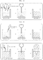
FIGS. 1 and 2 are views schematically illustrating a method of manufacturing liquid metal ink according to an embodiment of the present invention. -
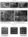
FIG. 3 is photographs illustrating an energizing test in various substrates, in the method of manufacturing liquid metal ink according to an embodiment of the present invention. -
FIG. 4 is photographs illustrating an energizing test according to a tensile test in a state in which ink is printed on a latex board, in the method of manufacturing liquid metal ink according to an embodiment of the present invention. -
FIG. 5 is photographs for comparing pattern images of inks according to various ethanol aqueous solutions, in the method of manufacturing liquid metal ink according to an embodiment of the present invention. -
FIG. 6 is a photograph illustrating a case in which an acid is added in an excess amount, in the method of manufacturing liquid metal ink according to an embodiment of the present invention. -
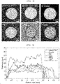
FIG. 7 is a photograph and graph illustrating a shape of liquid metal dropped on a foamex (foamed PVC) substrate, in the method of manufacturing liquid metal ink according to an embodiment of the present invention. -
FIGS. 8 and 9 are photographs and a graph illustrating shapes of liquid metal when dropping it on various substrates, in the method of manufacturing liquid metal ink according to an embodiment of the present invention. -
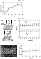
FIG. 10 is a resistance graph with respect to time from immediately after the ink pattern dries on the foamex substrate, in the method of manufacturing liquid metal ink according to an embodiment of the present invention. -
FIG. 11 is a view and a resistance graph with respect to time immediately after the ink pattern dries in a case in which Cr/Au electrodes are deposited on a foamed PVC and liquid metal ink is formed in a dot shape therebetween, and a case in which Cr/Au electrodes are deposited on a polyethylene terephthalate (PET) substrate and liquid metal ink is formed in a square shape therebetween, in the method of manufacturing liquid metal ink according to an embodiment of the present invention. -
FIG. 12 is a photograph and graph illustrating a change in the resistance according to the tensile test in a state in which the ink is printed on the latex board, in the method of manufacturing liquid metal ink according to an embodiment of the present invention. -
FIG. 13 is graphs illustrating the change in the resistance according to the bending and tensile tests in a state in which the ink manufactured by the method of manufacturing liquid metal ink according to an embodiment of the present invention is printed. -
FIG. 14 is graphs for comparing a particle diameter and a zeta potential of the liquid metal ink, in the method of manufacturing liquid metal ink according to an embodiment of the present invention. -
FIG. 15 is photographs illustrating patterns for three types of inks including ink requiring sintering, non-sintered ink, and only acid-added ink, in the method of manufacturing liquid metal ink according to an embodiment of the present invention. - A method of manufacturing liquid metal ink according to an embodiment of the present invention includes: (a) inputting a solvent into liquid metal in a container at room temperature; (b) performing oxide film-removing treatment on the liquid metal of step (a); and (c) dispersing the liquid metal that has undergone step (b) in a form of nanoparticles through ultrasonic treatment.
- Hereinafter, configurations, operations, and effects of a method of manufacturing liquid metal ink according to preferred embodiments will be described with reference to the accompanying drawings. For reference, in the drawings described below, each component is omitted or schematically illustrated for convenience and clarity, and the size of each component does not reflect an actual size. In addition, the same reference numerals are denoted to the same components throughout the specification, and reference numerals for the same components in individual drawings will be omitted.
- The method of manufacturing liquid metal ink according to an embodiment of the present invention may include: (a) inputting a solvent into room temperature liquid metal contained in a container; (b) performing oxide film-removing treatment on the liquid metal of step (a); and (c) dispersing the liquid metal that has undergone step (b) in a form of nanoparticles through ultrasonic treatment.
- In the conventional process of manufacturing ink using metal, since a reduction in the electrical conductivity occurs due to an oxide film formed around the metal, a sintering process for removing the oxide film should be necessarily performed. For the post-treatment process called sintering, adding either a pressing process or a heating process is required. To solve this problem, the present invention is intended to provide a method of manufacturing non-sintered liquid metal ink for process simplification. First, the inventive method includes the step of inputting liquid metal in a container, and inputting a solvent into the container. In this case, the liquid metal used herein is a metallic material which maintains a liquid phase at room temperature, and may include liquid metal made of a single element such as mercury or gallium, or liquid metal made of a gallium-based alloy such as a gallium-indium alloy, but it is limited thereto. In the present disclosure, a gallium-indium-tin alloy (Galinstan) is preferably used.
- Next, a solvent is input into the container containing the liquid metal added thereto. Herein, the solvent may include an ethanol aqueous solution in which absolute ethanol and water are mixed, and specifically, may include a 65% ethanol aqueous solution in which 65% of ethanol and 35% of water are mixed, or a 30% ethanol aqueous solution in which 30% of ethanol and 70% of water are mixed, but it is not limited thereto. In addition to the ethanol aqueous solution, various alcohol solvents such as methanol, ethanol, IPA, and etc. may be used. In this way, in the state in which the liquid metal is contained in the solvent, conventionally, the liquid metal is dispersed in the form of nanoparticles through ultrasonic treatment. However, in the present disclosure, the step of removing the oxide film is performed before the ultrasonic treatment step.
- According to a preferred feature of the present invention, in the step of removing the oxide film, a trace amount of acid may be input into the liquid metal in the container.
- In the step of removing the oxide film, the oxide film formed on the liquid metal is preferentially removed by inputting the trace amount of acid (hydrochloric acid is used in the present disclosure) in a state in which the liquid metal is contained in the container, and then the liquid metal contained in the solvent is subjected to ultrasonic treatment, such that the step of sintering the oxide film of the liquid metal dispersed in nanoparticles may be omitted. The liquid metal that has been subjected to ultrasonic treatment and dispersed in the nanoparticles may be manufactured as an emulsion ink to be used in various ways, such as a coating or a printing technique. The non-sintering liquid metal ink formed through the above-described method has advantages in that it has superior electrical conductivity compared to conventional carbon paste or conductive polymer-based conductive inks, and it is free to deform due to mechanical stimuli such as stretching or shrinkage compared to the ink composed of solid particles at room temperature.
- According to a preferred feature of the present invention, the inventive method may further include the step of inputting a surfactant or a conductive polymer for preventing cracks of the liquid metal, after the step of inputting the solvent to the container containing the liquid metal.
- In the process of printing the emulsion ink in which the liquid metal is dispersed in the form of nanoparticles through ultrasonic treatment, the ink composed of nanoparticles is a colloidal form, where a problem of the cracks may occur when forming a colloidal deposition after evaporation. In particular, there are problems in that, in the ink composed of metal-based nanoparticles, the dispersed metal particles have a high density, thereby colloidal particles may be precipitated, and in the case of liquid metal, merging between emulsions occurs due to its own high surface tension, and dispersion stability may be reduced over time. Accordingly, as one embodiment to prevent the above-described problems, the inventive method may further include the step of inputting a surfactant or a conductive polymer, after the solvent is input into the liquid metal. The surfactant may include a cationic surfactant such as cetrimonium bromide (CTAB), lysozyme protein (Lys), poly(4-vinyl-1-methyl-pyridinium bromide) (P4VMPB), etc., and the conductive polymer may include a water-soluble conductive polymer such as a poly(3,4-ethylenedioxythiophene)-polystyrenesulfonic acid (PEDOT-PSS) copolymer, polypyrrole-polystyrenesulfonic acid (PPY-PSS) copolymer, etc. When inputting the surfactant or the conductive polymer, an occurrence of microcracks may be prevented in advance and dispersion stability may be increased.
- According to a preferred feature of the present invention, the inventive method may further include the step of inputting polyvinylpyrrolidone to improve a coating quality of the liquid metal, after the step (a).
-
FIG. 15 is photographs illustrating patterns for three types of inks including ink requiring sintering, non-sintered ink, and only acid-added ink. Herein, the non-sintered liquid metal ink and the acid-added ink, generally had a larger particle diameter than the particle diameter of the liquid metal ink requiring sintering. In addition, although there is electrical conductivity even when acid is added, holes appeared in the pattern as shown in the right photograph ofFIG. 15 , and large droplets having several hundreds of micrometers were found due to excessive merging between droplets, and consequently, it showed an incomplete appearance, for example, a uniform pattern was not formed. However, after inputting the solvent to the liquid metal, when adding polyvinylpyrrolidone thereto, the pore formation of the pattern was largely reduced, and the quality of the pattern was improved, for example, no large droplets were found. - According to a preferred feature of the present invention, the inventive method may further include the step of primarily dispersing the liquid metal in the solvent through ultrasonic treatment, and re-dispersing the dispersed liquid metal through secondary ultrasonic treatment after performing the step of removing the oxide film.
In this case, due to the step of removing the oxide film by adding the acid, briefly, an oxide film-removing treatment, the surface tension of the liquid metal is increased, and thus there was a problem in that a stronger ultrasonic wave should be used when dispersing the liquid metal in the nanoparticles through ultrasonic treatment. Accordingly, power required for an ultrasonic device and heat generated by the ultrasonic wave would be increased. In order to prevent this problem, the oxide film-removing treatment is not performed immediately after inputting the solvent into the liquid metal in the container, but the oxide film is removed through the oxide film-removing treatment in which the liquid metal is primarily dispersed in the form of nanoparticles through ultrasonic treatment, and acid is added into the resulting emulsion ink, and then the dispersed liquid metal is re-dispersed through secondary ultrasonic treatment. Accordingly, there is an advantage in that it is possible to reduce the excessive use of power in the ultrasonic device and decrease the amount of heat generated by the ultrasonic wave. - According to a preferred feature of the present invention, the solvent in the step (a) may include 30 to 65% ethanol aqueous solution.
- As described above, the solvent may include an ethanol aqueous solution in which ethanol and water are mixed.
FIG. 16 illustrates scanning electron microscopic (SEM) images for evaporation patterns of the ink when a solvent including 100% ethanol and an ethanol aqueous solution including 65% ethanol and 35% water were used as a solvent of the ink. In the case of an ethanol aqueous solution including 65% ethanol and 35% water, partially connected liquid metal paths are formed in the pattern. Due to the path formed in this way, the electrical conductivity of the pattern is maintained even for the liquid metal in which the sintering process is omitted, and the liquid metal path may be formed even in an ethanol aqueous solution including a small amount of water. However, in the case of pure ethanol which does not include water at all, such a path is not formed and electrical conductivity is lost. This suggests that the presence of a certain amount of water in the solvent is related to an effect of removing the oxide film. That is, when using the ethanol aqueous solution including a certain amount of water in the solvent, the oxide film may be removed more efficiently. In addition, when the concentration of ethanol is less than 30%, there is a disadvantage in that the evaporation of the solvent is slow, and when the concentration of ethanol exceeds 65%, the effect of removing the oxide film on the pattern after the ink evaporates is reduced. Therefore, it could be seen that the ethanol aqueous solution preferably includes ethanol in a concentration of 30 to 65%. - As described above, the solvent may include the ethanol aqueous solution in which ethanol and water are mixed, and in the present disclosure, an experiment was performed on three aqueous solutions including E30% in which 30% of ethanol and 70% of water were mixed, E65% in which 65% of ethanol and 35% of water were mixed, and E100% including 100% of ethanol.
- According to a preferred feature of the present invention, in the step of removing the oxide film, a degree (X) of removing an oxide film from the liquid metal may be calculated by the following equation:

Dispersion medium is a hydrogen ion concentration of a dispersion medium including the ethanol aqueous solution in which ethanol and water are mixed, and 10 -pHInk is a hydrogen ion concentration value of ink manufactured in a state in which liquid metal is dispersed into the ethanol aqueous solution in which ethanol and water are mixed). - First, [1] 10 mL of ethanol + water is a dispersion medium including only ethanol aqueous solution not liquid metal and corresponds to a control group, and [2] 10 mL of liquid metal ink according to an embodiment of the present invention corresponds to an experimental group. In order to compare the pH of the dispersion medium and the ink depending on the oxide film-removing treatment, when the acid was not input and when 20 µL, 50 µL, 100 µL, and 200 µL of acids (herein, hydrochloric acid was used) were used, pH values of the dispersion medium and the ink were measured, and results thereof are shown in [Table 1] below.
[TABLE 1] Ethano 1 concen tratio nAcid X Acid 20 µL Acid 50 µL Acid 100 µL Acid 200 µL Note [1] 10 mL of ethanol + water E30% 8.69 2.95 1.48 - - Disper sion medium E65% 8.76 2.14 1.62 1.38 1.02 E100% 8.63 2.12 0.33 - - [2] 10 mL of liquid metal ink E30% 4.67 3.02 2.71 - - Ink E65% 4.62 2.63 2.46 2.34 2.13 (No patter n comple tion) E100% 7.44 2.41 1. 51 - - - When acid is added, a degree (X) of removing the oxide film of the dispersion medium and ink depending on the concentration of ethanol, that is, the value of X as an index indicating how much the oxide film of liquid metal has been removed may be calculated by the following equation.

- Wherein, 10-pH
Dispersion medium means a hydrogen ion concentration of a dispersion medium ink including the ethanol aqueous solution in which ethanol and water are mixed, and 10 -pHInk means a hydrogen ion concentration value of ink manufactured in a state in which liquid metal is dispersed into an ethanol aqueous solution in which ethanol and water are mixed. Since the concentration of the hydrogen ion is decreased as a larger amount of the oxide film reacts with the input acid, the higher the value of X, the more the oxide film reacts. Herein, the X value becomes O when no hydrogen ions react, and the X value becomes 1 when all hydrogen ions react. - Based on the case of inputting 50 µL of acid, the X value is 0.941 upon E30%, and the X value is 0.856 upon E65%. From this, the liquid metal that has undergone the oxide film-removing treatment had calculated X of 0.856 to 0.941 when the concentration of ethanol aqueous solution was 30 to 65%, thus it could be seen that most of the oxide film was removed.
-
FIG. 5 is photographs for comparing pattern images of inks according to various ethanol aqueous solutions, in the method of manufacturing liquid metal ink according to an embodiment of the present invention. - As shown in
FIG. 5 , in the case of E100% including 100% of ethanol, there was a problem in that the ink not only spreads well on the substrate, but also sufficient liquid metal is not left due to a high evaporation rate. Next, in the case of E30% which is a 30% ethanol aqueous solution, there was a disadvantage in that the degree of spreading of the ink on the substrate is relatively small, but the evaporation rate is low, such that the liquid metal is thickly accumulated, and thereby reducing the completeness of the pattern. In the case of 65% ethanol aqueous solution in which 65% of ethanol and 35% of water are mixed, the most appropriate values were shown in terms of the evaporation rate and degree of spreading of the ink. -
FIG. 6 is a photograph illustrating a case in which an acid is added in an excess amount, in the method of manufacturing liquid metal ink according to an embodiment of the present invention. - As the amount of acid added for the oxide film-removing treatment is increased, the pH is decreased, such that the oxide film may be effectively removed. However, when an excessive amount of acid is added, there is a problem in that the evaporation pattern of the ink is not completed and remains as liquid metal droplets. Accordingly, it could be seen that not only the evaporation rate and the degree of spreading of the ink on the substrate could be controlled according to a ratio of the ethanol in the solvent, but also the completeness of the pattern and the electrical conductivity were determined depending on the amount of the acid.
- As another experimental example, in the case in which the oxide film-removing treatment process was performed on the 65% ethanol aqueous solution by inputting 20 µL, 30 µL, and 50 µL of acids into the dispersion medium of the control group [1], and ink of the experimental group [2], each pH value was calculated, and the obtained values are shown in Table 2 below.
[TABLE 2] E65% 20 µL 30 µL 50 µL [1] 10 mL of ethanol + water 2.14 1.85 1.62 [2] 10 mL of liquid metal ink 2.63 2.5 2.46 X 0.6764 0.7761 0.8554 Electrical conductivity X O O - Herein, with respect to the above-described X value indicating the degree of removing the oxide film from the liquid metal, when 20 µL of acid was added, the X value was 0.6764, but the pattern after the ink evaporation was not conducted in the energizing test. This means that the it is not electrically conducted without performing a sintering process because the oxide film formed on the liquid metal is not effectively removed due to a small amount of the acid. Next, it was confirmed that the X value was 0.7761 when 30 µL of acid was added, and at this time, the pattern was conducted in the energizing test. Accordingly, it is preferable that the X value indicating the degree of removing the oxide film from the liquid metal is 0.7 or more.
-
FIG. 7 is a photograph and graph illustrating a shape of liquid metal dropped on a foamex substrate, in the method of manufacturing liquid metal ink according to an embodiment of the present invention. When 3 µL of liquid metal was dropped on the foamex substrate and the 3D topology was measured, it could be seen that the pattern had a thickness of about 60 µm. Further, although it is known that the general evaporation pattern of the colloid including nanoparticles exhibits a coffee ring effect that an edge of the pattern is thick and uniformity of the pattern is decreased, a uniform pattern may be obtained from the pattern result ofFIG. 5 . - In addition,
FIGS. 8 and 9 are photographs and a graph illustrating shapes of liquid metal when dropping it on various substrates. Similar to the experiment performed inFIG. 7 , it can be seen that, when 5 µL of liquid metal was dropped on different substrates and the 3D topology was measured, the formed PVC substrate had a thickness of about 25 to 30 µm and the PDMS substrate had a thickness of about 10 µm. In particular, it can be seen that the coffee ring effect does not appear at the edge of the pattern and a uniform pattern is obtained. -
FIG. 10 is a resistance graph with respect to time from immediately after the ink pattern dries on the foamex substrate, in the method of manufacturing liquid metal ink according to an embodiment of the present invention. - Herein, a resistance value was calculated from immediately after the evaporation was completed until 25 hours passed, but it can be seen that the electrical conductivity is sufficiently high because the resistance value is low at a level of several Ω.
- In addition,
FIG. 11 is a view and a resistance graph with respect to time immediately after the ink pattern dries in a case in which Cr/Au electrodes are deposited on a foamed PVC and liquid metal ink manufactured according to the method of manufacturing liquid metal ink of an embodiment of the present invention is formed in a dot shape therebetween, and a case in which Cr/Au electrodes are deposited on a polyethylene terephthalate (PET) substrate and liquid metal ink is formed in a square shape therebetween. As a result of performing an experiment for about 10 days, it could be seen that the electrical conductivity was high because the resistance value did not become larger than the level of several Ω. -
FIG. 12 is a photograph and graph illustrating a change in the resistance according to the tensile test in a state in which the ink is printed on the latex substrate, in the method of manufacturing liquid metal ink according to an embodiment of the present invention. Herein, the resistance of the pattern is increased by about 114% when comparing with the resistance before strain based on 0 to 125% of a strain rate (stretch rate) of the substrate. Considering the resistance of 2Ω or less inFIG. 6 , it can be seen that the pattern maintains the resistance at the level of several Ω even on the stretched substrate. - Further,
FIG. 13 is graphs illustrating the change in the resistance according to the bending and tensile tests in a state in which the ink manufactured by the method of manufacturing liquid metal ink according to an embodiment of the present invention is printed. A pattern of 2 cm × 2 cm on a PET substrate was used for bending, and a pattern of 4 cm × 1 cm (free stretching area 2 cm × 1 cm) on a PU substrate was used for stretching. In the case of the bending, the resistance was maintained almost constant, but in the case of the stretching, the initial resistance of 0.21Ω was increased by 14.2 times at 600% stretch rate, and from this result, it can be seen that the resistance is changed depending on the stretch rate. -
FIG. 14 is graphs for comparing a particle diameter and a zeta potential of the liquid metal ink, in the method of manufacturing liquid metal ink according to an embodiment of the present invention. The particle diameters of the ink were shown in a distribution of several hundred nm to several µm. In the present embodiment, a distribution having peaks of 715 nm and 2.2 µm was shown, but this distribution may vary depending on control of sonication power and time. Due to gallium ions, the zeta potential of the liquid metal ink had a positive voltage, and the zeta potential distribution exhibited the peak at around 50 mV. The zeta potential is related with the stability of a colloidal solution: when stability is good, a zeta potential of 40 mV or more is measured. Therefore, it can be seen that the liquid metal ink is a colloid with high stability. - Although preferred embodiments of the present invention have been described with reference to the accompanying drawings, the embodiments and drawings described and illustrated in the present disclosure are simply the most preferred embodiment and do not represent all the technical sprites of the present invention, and it will be understood that various modifications and equivalents may be made to take the place of the embodiments at the time of filling the present application. Thus, it is clear that the above-described embodiments are illustrative in all aspects and do not limit the present disclosure. The scope of the present disclosure is defined by the following claims rather than by the detailed description of the embodiment. It shall be understood that all modifications and embodiments conceived from the meaning and scope of the claims and their equivalents are included in the scope of the present disclosure.
Claims (8)
- A method of manufacturing liquid metal ink comprising:(a) inputting a solvent into liquid metal in a container at room temperature;(b) performing oxide film-removing treatment on the liquid metal of step (a); and(c) dispersing the liquid metal that has undergone step (b) in a form of nanoparticles through ultrasonic treatment.
- The method of manufacturing liquid metal ink according to claim 1, wherein in the step (b),
an acid is input into the liquid metal in the container. - The method of manufacturing liquid metal ink according to claim 2, further comprising inputting a surfactant or conductive polymer for preventing cracks of the liquid metal, after the step (a).
- The method of manufacturing liquid metal ink according to claim 1, further comprising: primarily dispersing the liquid metal in a form of nanoparticles through ultrasonic treatment, after the step (a); and
re-dispersing the dispersed liquid metal through secondary ultrasonic treatment, after performing the step (b). - The method of manufacturing liquid metal ink according to claim 1, wherein the solvent in the step (a) includes a 30 to 65% ethanol aqueous solution.
- The method of manufacturing liquid metal ink according to claim 1, wherein in the step (b),a degree (X) of removing an oxide film from the liquid metal is calculated by the following equation:
 (wherein, 10-pH
Dispersion medium is a hydrogen ion concentration of a dispersion medium including an ethanol aqueous solution in which ethanol and water are mixed, and 10-pHInk is a hydrogen ion concentration value of ink manufactured in a state in which liquid metal is dispersed into an ethanol aqueous solution in which ethanol and water are mixed). - The method of manufacturing liquid metal ink according to claim 3, wherein the surfactant includes cetrimonium bromide (CTAB), lysozyme protein (Lys), or poly(4-vinyl-1-methyl-pyridinium bromide) (P4VMPB), and
the conductive polymer includes a poly(3,4-ethylenedioxythiophene)-polystyrenesulfonic acid (PEDOT-PSS) copolymer, or polypyrrole-polystyrenesulfonic acid (PPY-PSS) copolymer. - The method of manufacturing liquid metal ink according to claim 2, further comprising inputting polyvinylpyrrolidone to improve a coating quality of the liquid metal, after the step (a) .
Applications Claiming Priority (2)
| Application Number | Priority Date | Filing Date | Title |
|---|---|---|---|
| KR20210005073 | 2021-01-14 | ||
| PCT/KR2021/019827 WO2022154312A1 (en) | 2021-01-14 | 2021-12-24 | Method for producing non-sintered liquid metal ink |
Publications (2)
| Publication Number | Publication Date |
|---|---|
| EP4071218A1 true EP4071218A1 (en) | 2022-10-12 |
| EP4071218A4 EP4071218A4 (en) | 2024-01-17 |
Family
ID=82448354
Family Applications (1)
| Application Number | Title | Priority Date | Filing Date |
|---|---|---|---|
| EP21876738.2A Pending EP4071218A4 (en) | 2021-01-14 | 2021-12-24 | Method for producing non-sintered liquid metal ink |
Country Status (4)
| Country | Link |
|---|---|
| US (1) | US11920043B2 (en) |
| EP (1) | EP4071218A4 (en) |
| KR (1) | KR102719657B1 (en) |
| WO (1) | WO2022154312A1 (en) |
Cited By (1)
| Publication number | Priority date | Publication date | Assignee | Title |
|---|---|---|---|---|
| CN115975411A (en) * | 2023-01-03 | 2023-04-18 | 山东大学 | Liquid metal conductive coating with cooperative deformability and preparation method thereof |
Families Citing this family (7)
| Publication number | Priority date | Publication date | Assignee | Title |
|---|---|---|---|---|
| KR102834603B1 (en) * | 2022-01-21 | 2025-07-17 | 한국과학기술원 | High-conductivity PEDOT:PSS and ionic liquid composite ink, manufacturing method and application thereof |
| KR102654440B1 (en) * | 2022-06-13 | 2024-04-04 | 경희대학교 산학협력단 | Liquid metal-based electrode and manufacturing method thereof |
| KR102788478B1 (en) * | 2022-10-04 | 2025-04-01 | 광주과학기술원 | Conductive water ink comprising liquid metal nanoparticle-conjugated polymer complex for and preparation method thereof |
| KR102601704B1 (en) | 2023-02-13 | 2023-11-14 | 한국과학기술원 | Thin-film liquid metal electrode, its manufacturing method using sequential deposition and stretchable electronic device using the electrode manufactured therefrom |
| CN116694141B (en) * | 2023-06-28 | 2025-03-04 | 香港中文大学(深圳) | Printable liquid metal ink and preparation method thereof |
| WO2025165538A1 (en) * | 2024-01-31 | 2025-08-07 | The Penn State Research Foundation | Self-assembly enabled printable asymmetric self-insulated stretchable conductor |
| CN119794356B (en) * | 2025-01-03 | 2025-11-28 | 哈尔滨工业大学 | Preparation method and application of flexible wearable wireless data glove |
Family Cites Families (11)
| Publication number | Priority date | Publication date | Assignee | Title |
|---|---|---|---|---|
| US8506849B2 (en) | 2008-03-05 | 2013-08-13 | Applied Nanotech Holdings, Inc. | Additives and modifiers for solvent- and water-based metallic conductive inks |
| KR101963801B1 (en) | 2011-03-29 | 2019-08-01 | 한국과학기술연구원 | conductive ink composition, method for manufacturing the same and method for manufacturing conductive thin layer using the same |
| KR101481629B1 (en) | 2011-08-11 | 2015-01-16 | 주식회사 아모그린텍 | Conductive Metal Nano Particle Ink and Manufacturing Method thereof |
| US9630161B2 (en) * | 2012-03-15 | 2017-04-25 | The Regents Of The University Of California | Metal alloy nanoparticle synthesis via self-assembled monolayer formation and ultrasound |
| KR101635849B1 (en) * | 2014-12-04 | 2016-07-21 | 전남대학교산학협력단 | Liquid metal ink injection type of printer cartridge and printer system thereby |
| KR101890888B1 (en) * | 2017-02-09 | 2018-08-22 | 울산과학기술원 | Carbon-eutectic gallium indium composite material, and method of manufacturing the same, and electrode material having the same |
| KR101993813B1 (en) * | 2017-12-11 | 2019-06-27 | 울산과학기술원 | Room temperature liquid metal capsule ink, method of manufacturing the same, and room temperature liquid metal capsule conductive wire formed by the same |
| CN108384327B (en) * | 2018-04-27 | 2021-07-30 | 国家纳米科学中心 | Stretch-induced conductive liquid metal particle-based conductive ink, preparation method and application thereof |
| US10800948B2 (en) * | 2018-08-02 | 2020-10-13 | Xerox Corporation | Conductive adhesive compositions and method for the same |
| CN111718617A (en) * | 2020-07-09 | 2020-09-29 | 东莞职业技术学院 | Nano metal conductive ink capable of being printed in graphical mode and preparation method thereof |
| CN111774576A (en) * | 2020-07-09 | 2020-10-16 | 东莞职业技术学院 | Preparation method of nano metal particles |
-
2021
- 2021-12-01 KR KR1020210170296A patent/KR102719657B1/en active Active
- 2021-12-24 WO PCT/KR2021/019827 patent/WO2022154312A1/en not_active Ceased
- 2021-12-24 EP EP21876738.2A patent/EP4071218A4/en active Pending
- 2021-12-24 US US17/768,708 patent/US11920043B2/en active Active
Cited By (1)
| Publication number | Priority date | Publication date | Assignee | Title |
|---|---|---|---|---|
| CN115975411A (en) * | 2023-01-03 | 2023-04-18 | 山东大学 | Liquid metal conductive coating with cooperative deformability and preparation method thereof |
Also Published As
| Publication number | Publication date |
|---|---|
| KR20220103028A (en) | 2022-07-21 |
| EP4071218A4 (en) | 2024-01-17 |
| WO2022154312A1 (en) | 2022-07-21 |
| KR102719657B1 (en) | 2024-10-21 |
| US11920043B2 (en) | 2024-03-05 |
| US20230159771A1 (en) | 2023-05-25 |
Similar Documents
| Publication | Publication Date | Title |
|---|---|---|
| US11920043B2 (en) | Method of manufacturing non-sintered liquid metal ink | |
| KR102297023B1 (en) | Ferromagnetic metal nanowire dispersion and method for manufacturing same | |
| US10400119B2 (en) | Method and apparatus for aerosol-based three-dimensional (3D) printing of flexible graphene electronic devices | |
| EP4122989B1 (en) | Conductive liquid metal microparticles comprising hydrogen-doped liquid metal oxide, conductive ink comprising same, and preparation method therefor | |
| KR101276237B1 (en) | Low sintering temperatures Conducting metal layer and the preparation method thereof | |
| EP3508286B1 (en) | Silver-coated alloy powder, electrically conductive paste, electronic part, and electric device | |
| EP1887106B1 (en) | Metal coating, Forming Method Thereof and Metal Wiring | |
| JP6355240B2 (en) | Silver fine particle dispersion | |
| WO2003038838A1 (en) | Ag COMPOUND PASTE | |
| US20210155818A1 (en) | Copper Oxide Ink and Method for Producing Conductive Substrate Using Same, Product Containing Coating Film and Method for Producing Product Using Same, Method for Producing Product with Conductive Pattern, and Product with Conductive Pattern | |
| Pajor-Świerzy et al. | Application of metallic inks based on nickel-silver core–shell nanoparticles for fabrication of conductive films | |
| CN115171978B (en) | High-conductivity aqueous slurry, preparation method thereof and high-conductivity thin film | |
| CN105981111A (en) | Conductive paste and method for manufacturing conductive film using same | |
| KR101767981B1 (en) | Wide field temperature sensor of contraction type using ink of temperature variation type and mathod for manufacturing the same | |
| TW202038257A (en) | Conductive paste, substrate with conductive film, and method for producing substrate with conductive film | |
| KR20150118801A (en) | Conductive composite Cu ink and light sintering method using the same | |
| KR101584202B1 (en) | The product method of ptc calorific plate using ptc ink for gravure | |
| JP6609153B2 (en) | Substrate for printed wiring board, printed wiring board and electronic component | |
| TWI597319B (en) | Dispersant, metal particle dispersion for electroconductive substrate, and method for producing electroconductive substrate | |
| CN101312800B (en) | Liquid colloidal dispersion of silver particles, coating liquid for forming silver film, manufacturing method and silver film | |
| KR20230171195A (en) | Liquid metal-based electrode and manufacturing method thereof | |
| CN119698671A (en) | Composition for forming conductive bonding material, conductive bonding material, device, and method for producing conductive bonding material | |
| JP5072228B2 (en) | Method for producing metal coating | |
| KR102815603B1 (en) | Manufacturing method for metal nanoweb | |
| Bae et al. | Synthesis and characterization of thermo-reversible conductive hydrogel toward smart electrodes |
Legal Events
| Date | Code | Title | Description |
|---|---|---|---|
| STAA | Information on the status of an ep patent application or granted ep patent |
Free format text: STATUS: UNKNOWN |
|
| STAA | Information on the status of an ep patent application or granted ep patent |
Free format text: STATUS: THE INTERNATIONAL PUBLICATION HAS BEEN MADE |
|
| PUAI | Public reference made under article 153(3) epc to a published international application that has entered the european phase |
Free format text: ORIGINAL CODE: 0009012 |
|
| STAA | Information on the status of an ep patent application or granted ep patent |
Free format text: STATUS: REQUEST FOR EXAMINATION WAS MADE |
|
| 17P | Request for examination filed |
Effective date: 20220413 |
|
| AK | Designated contracting states |
Kind code of ref document: A1 Designated state(s): AL AT BE BG CH CY CZ DE DK EE ES FI FR GB GR HR HU IE IS IT LI LT LU LV MC MK MT NL NO PL PT RO RS SE SI SK SM TR |
|
| A4 | Supplementary search report drawn up and despatched |
Effective date: 20231215 |
|
| RIC1 | Information provided on ipc code assigned before grant |
Ipc: C09D 11/033 20140101ALI20231212BHEP Ipc: C09D 11/106 20140101ALI20231212BHEP Ipc: C09D 11/037 20140101ALI20231212BHEP Ipc: C09D 11/52 20140101AFI20231212BHEP |
|
| DAV | Request for validation of the european patent (deleted) | ||
| DAX | Request for extension of the european patent (deleted) | ||
| STAA | Information on the status of an ep patent application or granted ep patent |
Free format text: STATUS: EXAMINATION IS IN PROGRESS |
|
| 17Q | First examination report despatched |
Effective date: 20250611 |