EP4070984A2 - Rotation angle detecting apparatus and power transmission and receiving system for vehicle - Google Patents
Rotation angle detecting apparatus and power transmission and receiving system for vehicle Download PDFInfo
- Publication number
- EP4070984A2 EP4070984A2 EP22163247.4A EP22163247A EP4070984A2 EP 4070984 A2 EP4070984 A2 EP 4070984A2 EP 22163247 A EP22163247 A EP 22163247A EP 4070984 A2 EP4070984 A2 EP 4070984A2
- Authority
- EP
- European Patent Office
- Prior art keywords
- distance measuring
- vehicle
- measuring sensor
- distance
- unit
- Prior art date
- Legal status (The legal status is an assumption and is not a legal conclusion. Google has not performed a legal analysis and makes no representation as to the accuracy of the status listed.)
- Granted
Links
Images


Classifications
-
- G—PHYSICS
- G01—MEASURING; TESTING
- G01B—MEASURING LENGTH, THICKNESS OR SIMILAR LINEAR DIMENSIONS; MEASURING ANGLES; MEASURING AREAS; MEASURING IRREGULARITIES OF SURFACES OR CONTOURS
- G01B21/00—Measuring arrangements or details thereof, where the measuring technique is not covered by the other groups of this subclass, unspecified or not relevant
- G01B21/22—Measuring arrangements or details thereof, where the measuring technique is not covered by the other groups of this subclass, unspecified or not relevant for measuring angles or tapers; for testing the alignment of axes
-
- B—PERFORMING OPERATIONS; TRANSPORTING
- B60—VEHICLES IN GENERAL
- B60L—PROPULSION OF ELECTRICALLY-PROPELLED VEHICLES; SUPPLYING ELECTRIC POWER FOR AUXILIARY EQUIPMENT OF ELECTRICALLY-PROPELLED VEHICLES; ELECTRODYNAMIC BRAKE SYSTEMS FOR VEHICLES IN GENERAL; MAGNETIC SUSPENSION OR LEVITATION FOR VEHICLES; MONITORING OPERATING VARIABLES OF ELECTRICALLY-PROPELLED VEHICLES; ELECTRIC SAFETY DEVICES FOR ELECTRICALLY-PROPELLED VEHICLES
- B60L53/00—Methods of charging batteries, specially adapted for electric vehicles; Charging stations or on-board charging equipment therefor; Exchange of energy storage elements in electric vehicles
- B60L53/10—Methods of charging batteries, specially adapted for electric vehicles; Charging stations or on-board charging equipment therefor; Exchange of energy storage elements in electric vehicles characterised by the energy transfer between the charging station and the vehicle
- B60L53/12—Inductive energy transfer
- B60L53/126—Methods for pairing a vehicle and a charging station, e.g. establishing a one-to-one relation between a wireless power transmitter and a wireless power receiver
-
- B—PERFORMING OPERATIONS; TRANSPORTING
- B60—VEHICLES IN GENERAL
- B60L—PROPULSION OF ELECTRICALLY-PROPELLED VEHICLES; SUPPLYING ELECTRIC POWER FOR AUXILIARY EQUIPMENT OF ELECTRICALLY-PROPELLED VEHICLES; ELECTRODYNAMIC BRAKE SYSTEMS FOR VEHICLES IN GENERAL; MAGNETIC SUSPENSION OR LEVITATION FOR VEHICLES; MONITORING OPERATING VARIABLES OF ELECTRICALLY-PROPELLED VEHICLES; ELECTRIC SAFETY DEVICES FOR ELECTRICALLY-PROPELLED VEHICLES
- B60L53/00—Methods of charging batteries, specially adapted for electric vehicles; Charging stations or on-board charging equipment therefor; Exchange of energy storage elements in electric vehicles
- B60L53/30—Constructional details of charging stations
- B60L53/35—Means for automatic or assisted adjustment of the relative position of charging devices and vehicles
- B60L53/36—Means for automatic or assisted adjustment of the relative position of charging devices and vehicles by positioning the vehicle
-
- B—PERFORMING OPERATIONS; TRANSPORTING
- B60—VEHICLES IN GENERAL
- B60L—PROPULSION OF ELECTRICALLY-PROPELLED VEHICLES; SUPPLYING ELECTRIC POWER FOR AUXILIARY EQUIPMENT OF ELECTRICALLY-PROPELLED VEHICLES; ELECTRODYNAMIC BRAKE SYSTEMS FOR VEHICLES IN GENERAL; MAGNETIC SUSPENSION OR LEVITATION FOR VEHICLES; MONITORING OPERATING VARIABLES OF ELECTRICALLY-PROPELLED VEHICLES; ELECTRIC SAFETY DEVICES FOR ELECTRICALLY-PROPELLED VEHICLES
- B60L53/00—Methods of charging batteries, specially adapted for electric vehicles; Charging stations or on-board charging equipment therefor; Exchange of energy storage elements in electric vehicles
- B60L53/30—Constructional details of charging stations
- B60L53/35—Means for automatic or assisted adjustment of the relative position of charging devices and vehicles
- B60L53/38—Means for automatic or assisted adjustment of the relative position of charging devices and vehicles specially adapted for charging by inductive energy transfer
-
- B—PERFORMING OPERATIONS; TRANSPORTING
- B62—LAND VEHICLES FOR TRAVELLING OTHERWISE THAN ON RAILS
- B62D—MOTOR VEHICLES; TRAILERS
- B62D15/00—Steering not otherwise provided for
- B62D15/02—Steering position indicators ; Steering position determination; Steering aids
- B62D15/027—Parking aids, e.g. instruction means
- B62D15/0285—Parking performed automatically
-
- G—PHYSICS
- G01—MEASURING; TESTING
- G01B—MEASURING LENGTH, THICKNESS OR SIMILAR LINEAR DIMENSIONS; MEASURING ANGLES; MEASURING AREAS; MEASURING IRREGULARITIES OF SURFACES OR CONTOURS
- G01B21/00—Measuring arrangements or details thereof, where the measuring technique is not covered by the other groups of this subclass, unspecified or not relevant
- G01B21/16—Measuring arrangements or details thereof, where the measuring technique is not covered by the other groups of this subclass, unspecified or not relevant for measuring distance of clearance between spaced objects
-
- H—ELECTRICITY
- H02—GENERATION; CONVERSION OR DISTRIBUTION OF ELECTRIC POWER
- H02J—ELECTRIC POWER NETWORKS; CIRCUIT ARRANGEMENTS OR SYSTEMS FOR SUPPLYING OR DISTRIBUTING ELECTRIC POWER; SYSTEMS FOR STORING ELECTRIC ENERGY
- H02J50/00—Circuit arrangements or systems for wireless supply or distribution of electric power
- H02J50/90—Circuit arrangements or systems for wireless supply or distribution of electric power involving detection or optimisation of position, e.g. alignment
-
- B—PERFORMING OPERATIONS; TRANSPORTING
- B60—VEHICLES IN GENERAL
- B60L—PROPULSION OF ELECTRICALLY-PROPELLED VEHICLES; SUPPLYING ELECTRIC POWER FOR AUXILIARY EQUIPMENT OF ELECTRICALLY-PROPELLED VEHICLES; ELECTRODYNAMIC BRAKE SYSTEMS FOR VEHICLES IN GENERAL; MAGNETIC SUSPENSION OR LEVITATION FOR VEHICLES; MONITORING OPERATING VARIABLES OF ELECTRICALLY-PROPELLED VEHICLES; ELECTRIC SAFETY DEVICES FOR ELECTRICALLY-PROPELLED VEHICLES
- B60L53/00—Methods of charging batteries, specially adapted for electric vehicles; Charging stations or on-board charging equipment therefor; Exchange of energy storage elements in electric vehicles
- B60L53/30—Constructional details of charging stations
- B60L53/35—Means for automatic or assisted adjustment of the relative position of charging devices and vehicles
- B60L53/37—Means for automatic or assisted adjustment of the relative position of charging devices and vehicles using optical position determination, e.g. using cameras
Definitions
- the disclosure relates to a rotation angle detecting apparatus that detects a relative rotation angle of an in-vehicle unit with respect to a ground unit, and a power transmission and receiving system for a vehicle.
- JP 2017-200328 A describes a noncontact power transmission and receiving system for a vehicle.
- a ground-side primary coil (power transmission coil) transmits electric power to a vehicle-side secondary coil (power receiving coil) in a noncontact manner.
- the relative position and inclination of the secondary coil with respect to the primary coil are calculated based on a coupling coefficient between the primary coil and the secondary coil and a change in the coupling coefficient over time.
- the disclosure enables detection of a relative rotation angle of an in-vehicle unit with respect to a ground unit with the use of a simple configuration.
- a first aspect of the disclosure relates to a rotation angle detecting apparatus.
- the rotation angle detecting apparatus detects a relative rotation angle of an in-vehicle unit with respect to a ground unit.
- the ground unit is one of a power transmission unit and a power receiving unit and is disposed in a parking space.
- the in-vehicle unit is the other one of the power transmission unit and the power receiving unit and is mounted on a vehicle at a location at which the in-vehicle unit is able to face the ground unit. When the ground unit is viewed from above in a vertical direction, the ground unit has a linear side facing toward the vehicle that approaches the ground unit.
- the rotation angle detecting apparatus includes a first distance measuring sensor, a second distance measuring sensor, a rotation angle sensor, and a processor.
- the first distance measuring sensor and the second distance measuring sensor are mounted on the vehicle so as to be arranged in a right and left direction of the vehicle and to face a road surface at a location at which the first distance measuring sensor and the second distance measuring sensor are able to face the ground unit at a time of parking.
- the rotation angle sensor is configured to detect a rotation angle of a wheel rotary shaft of the vehicle or a rotation angle of a rotary shaft that rotates with the wheel rotary shaft.
- the processor is configured to, after the vehicle starts parking, acquire a first timing at which one of the first distance measuring sensor and the second distance measuring sensor begins to face the ground unit based on a change of an output signal of the one of the first distance measuring sensor and the second distance measuring sensor.
- the processor is configured to, after the first timing is detected, acquire a second timing at which the other one of the first distance measuring sensor and the second distance measuring sensor begins to face the ground unit, based on a change of an output signal of the other one of the first distance measuring sensor and the second distance measuring sensor.
- the processor is configured to calculate a moving distance of the vehicle during a period from the first timing to the second timing based on an output signal of the rotation angle sensor.
- the processor is configured to calculate an arc tangent value of a value obtained by dividing the calculated moving distance by a distance between the first distance measuring sensor and the second distance measuring sensor as a yaw angle.
- the yaw angle is a rotation angle of the in-vehicle unit with respect to the ground unit about a vertical axis of the vehicle.
- the first distance measuring sensor and the second distance measuring sensor may be installed in the in-vehicle unit.
- the rotation angle detecting apparatus may further include a third distance measuring sensor and a fourth distance measuring sensor arranged in the right and left direction and installed in the in-vehicle unit so as to face a road surface.
- the third distance measuring sensor may be disposed apart from the first distance measuring sensor by a predetermined distance in a front and rear direction of the vehicle.
- the fourth distance measuring sensor may be disposed apart from the second distance measuring sensor by the predetermined distance in the front and rear direction.
- the processor may be configured to calculate a first difference between an average value of a first distance detected by the first distance measuring sensor and a third distance detected by the third distance measuring sensor and an average value of a second distance detected by the second distance measuring sensor and a fourth distance detected by the fourth distance measuring sensor.
- the processor may be configured to calculate an arc sine value of a value obtained by dividing the calculated first difference by the distance between the first distance measuring sensor and the second distance measuring sensor as a roll angle that is a rotation angle of the in-vehicle unit with respect to the ground unit about a longitudinal axis of the vehicle.
- the processor may be configured to calculate a second difference between an average value of a first distance detected by the first distance measuring sensor and a second distance detected by the second distance measuring sensor and an average value of a third distance detected by the third distance measuring sensor and a fourth distance detected by the fourth distance measuring sensor.
- the processor may be configured to calculate an arc sine value of a value obtained by dividing the calculated second difference by a distance between the first distance measuring sensor and the third distance measuring sensor as a pitch angle that is a rotation angle of the in-vehicle unit with respect to the ground unit about a transverse axis of the vehicle.
- the in-vehicle unit may include a power transmission coil or a power receiving coil for transmitting or receiving electric power to or from the ground unit in a noncontact manner.
- the first distance measuring sensor, the second distance measuring sensor, the third distance measuring sensor, and the fourth distance measuring sensor may be disposed so as to surround the power transmission coil or the power receiving coil disposed in the in-vehicle unit.
- the rotation angle sensor may be a resolver configured to detect a rotation angle of a rotary shaft of an electric motor that drives the vehicle.
- a second aspect of the disclosure relates to a power transmission and receiving system for a vehicle.
- the power transmission and reception system includes the rotation angle detecting apparatus.
- the power transmission and receiving system may be configured to transmit or receive electric power between the power transmission unit and the power receiving unit in a noncontact manner.
- the yaw angle of the in-vehicle unit with respect to the ground unit can be detected with the use of a simple configuration made up of a pair of distance measuring sensors (the first and second distance measuring sensors) and the rotation angle sensor of the vehicle.
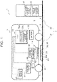
- FIG. 1 is a diagram schematically showing an example of the configuration of a power transmission and receiving system 1 for a vehicle, to which a rotation angle detecting apparatus 50 according to a first embodiment is applied.
- the power transmission and receiving system 1 includes a power transmission apparatus 2 installed at a ground side, and a power receiving apparatus 4 mounted on a vehicle 3.
- the power transmission and receiving system 1 is configured to transfer electric power from the power transmission apparatus 2 to the power receiving apparatus 4 by using, for example, a magnetic field resonance system.
- a noncontact power transfer system is not limited, and another system, such as an electromagnetic induction system, may be used.
- the power transmission apparatus 2 is installed in a parking space 5 of the vehicle 3.
- the power transmission apparatus 2 includes a power transmission unit (hereinafter, also referred to as ground unit) 21.
- the power transmission apparatus 2 is made up of the ground unit 21 and a power transmission station 22 as an example.
- the ground unit 21 includes a case 23.
- the case 23 accommodates a power transmission coil 24.
- the power transmission station 22 is electrically connected to the ground unit 21.
- the power transmission station 22 includes an alternating current power supply 25 and a power transmission circuit 26.
- the alternating current power supply 25 supplies electric power to the ground unit 21 (power transmission coil 24) via the power transmission circuit 26.
- the power transmission circuit 26 includes an inverter and controls a current flowing through the power transmission coil 24.
- the ground unit 21 is placed on a road surface 6 and has a step 27 between a top surface 23a and the road surface 6.
- the height of the step 27 is less than the clearance between the road surface 6 and the bottom surface of the vehicle 3.
- the ground unit 21 just needs to be disposed on the road surface 6 so as to have the step 27 that can be detected by first and second distance measuring sensors 34, 35 (described later) and may also be, for example, embedded in the road surface 6.
- the step 27 may be formed such that the top surface 23a is lower than the road surface 6 instead of an example in which the top surface 23a is higher than the road surface 6 as shown in FIG. 1 .
- the power transmission station 22 is installed at, for example, one end of the parking space 5.
- the power receiving apparatus 4 mounted on the vehicle 3 includes a power receiving unit (hereinafter, also referred to as in-vehicle unit) 41.
- the power receiving apparatus 4 is made up of the in-vehicle unit 41 and a power receiving circuit 42 as an example.
- the in-vehicle unit 41 is mounted on the vehicle 3 at a location at which the in-vehicle unit 41 is able to face the ground unit 21 (that is, the bottom of the vehicle 3).
- the in-vehicle unit 41 receives electric power transferred from the ground unit (power transmission unit) 21.
- the in-vehicle unit 41 includes a case 43.
- the case 43 accommodates a power receiving coil 44.
- the power receiving coil 44 receives electric power transferred from the power transmission coil 24 in a noncontact manner in a state of facing the power transmission coil 24.
- the power receiving circuit 42 includes a rectifier that converts alternating-current power received by the power receiving coil 44 to direct-current power by rectifying the alternating-current power.
- the vehicle 3 includes an electric motor 31 serving as a driving source, and a battery 32 that supplies electric power to the electric motor 31 in addition to the power receiving apparatus 4.
- the vehicle 3 is an electrically-powered vehicle.
- the vehicle 3 is, for example, a battery electric vehicle.
- Other examples of the vehicle 3 include a hybrid vehicle including an internal combustion engine together with the electric motor 31 as a driving source, and a fuel cell electric vehicle.
- the battery 32 is, for example, a lithium ion battery and is connected to the power receiving circuit 42. The battery 32 is charged with electric power supplied from the ground-side power transmission apparatus 2 via the power receiving apparatus 4.
- the vehicle 3 includes an electronic control unit (ECU) 33.
- the ECU 33 is a computer that executes various processes related to the vehicle 3. Specifically, the processes to be executed by the ECU 33 include a process related to control over the electric motor 31, a process related to control over electric power received from the power transmission apparatus 2, and a process related to detecting various rotation angles (yaw angle ⁇ in the first embodiment) (described later).
- the ECU 33 includes a processor 33a and a storage device 33b.
- the processor 33a reads out a program stored in the storage device 33b and runs the program.
- a plurality of the ECUs 33 may be provided.
- the process related to detecting a yaw angle ⁇ may be executed by a dedicated ECU (processor).
- the vehicle 3 includes the pair of distance measuring sensors (first and second distance measuring sensors) 34, 35 and a resolver 36 in order to detect a yaw angle ⁇ .
- the details of the distance measuring sensors 34, 35 will be described later with reference to FIG. 5 .
- the resolver 36 detects the rotation angle of the rotary shaft of the electric motor 31.
- the rotary shaft of the electric motor 31 may be regarded as an example of a rotary shaft that rotates in synchronization with the rotary shafts of wheels 7 of the vehicle 3. Therefore, the ECU 33 is capable of calculating a moving distance of the vehicle 3 based on the rotation angle of the electric motor 31 (more specifically, the rotation angle, a gear ratio between the electric motor 31 and each wheel 7, and the radius of each wheel 7 (tire)).
- the resolver 36 may be regarded as an example of a rotation angle sensor according to the disclosure.
- the rotation angle sensor may be, for example, a wheel speed sensor that detects the rotation angle of the rotary shaft of any one of the wheels 7 instead of the resolver 36.
- the resolver 36 used to detect a rotation angle required to control the electric motor 31 is generally capable of detecting a rotation angle with high accuracy as compared to a wheel speed sensor.
- FIG. 2 is a view from above the vehicle 3 approaching the parking space 5 in the vertical direction (Z-axis direction).
- the reference sign 8 indicates a parking lot line that defines the parking space 5.
- a longitudinal axis, a transverse axis, and a vertical axis of the vehicle 3 are respectively referred to as X-axis, Y-axis, and Z-axis (see FIG. 2 and FIG. 5 and the like (described later)). More specifically, FIG. 2 shows back end parking as an example; however, a method of calculating a yaw angle ⁇ , which will be described below, is also applicable to front end parking.
- the relative position and relative rotation angle of the in-vehicle unit with respect to the ground unit are required to be accurately detected at the time of transmitting and receiving electric power in a noncontact manner. This is to determine whether each of the relative position and the relative rotation angle falls within a range in which noncontact charging is possible.
- the relative position includes an X-axis direction position, a Y-axis direction position, and a Z-axis direction position
- the relative rotation angle includes a yaw angle ⁇ (a rotation angle about the Z-axis), a roll angle ⁇ (a rotation angle about the X-axis), and a pitch angle ⁇ (a rotation angle about the Y-axis).
- FIG. 3A and FIG. 3B are also views of the ground unit 21 and the in-vehicle unit 41 when viewed in the Z-axis direction as in the case of FIG. 2 .
- the longitudinal axis (X-axis) of the vehicle 3 is parallel to the parking lot line 8.
- an axis parallel to the parking lot line 8 in an XY-plane is used as a reference axis L1 of the ground unit 21.
- An axis parallel to the X-axis (longitudinal axis) of the vehicle 3 is used as a reference axis L2 of the in-vehicle unit 41.
- the vehicle 3 is parked in a state where the longitudinal axis (X-axis) is parallel to the parking lot line 8.
- the reference axis L1 and the reference axis L2 are parallel to each other, so the yaw angle ⁇ is zero.
- the reference axis L2 is inclined with respect to the reference axis L1. Therefore, the inclination angle of the reference axis L2 with respect to the reference axis L1 is determined as the yaw angle ⁇ .
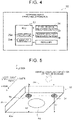
- FIG. 4 is a block diagram showing the configuration of the rotation angle detecting apparatus 50 according to the first embodiment.
- the rotation angle detecting apparatus 50 is made up of the ECU 33, the first and second distance measuring sensors 34, 35, and the resolver 36.
- FIG. 5 is a perspective view of the in-vehicle unit 41 shown in FIG. 1 when viewed from the lower side of the vehicle 3 in the vertical direction.
- a bottom surface 43a of the case 43 of the in-vehicle unit 41 faces the road surface 6 or the ground unit 21.
- the in-vehicle unit 41 is mounted on the vehicle 3 such that the bottom surface 43a is parallel to the XY-plane.
- the first distance measuring sensor 34 is installed in the in-vehicle unit 41 so as to face downward in the Z-axis direction, that is, so as to face the road surface 6 and detects a distance D1 to the road surface 6.
- the second distance measuring sensor 35 is installed in the in-vehicle unit 41 so as to face downward in the Z-axis direction, that is, so as to face the road surface 6 and detects a distance D2 to the road surface 6.
- the first distance measuring sensor 34 and the second distance measuring sensor 35 are disposed so as to be arranged in a right and left direction (Y-axis direction) of the vehicle 3.
- the distance between the first distance measuring sensor 34 and the second distance measuring sensor 35 (hereinafter, referred to as sensor-to-sensor distance DS1) is set so as to be shorter than the width of the ground unit 21 in a direction perpendicular to the reference axis L1.
- sensor-to-sensor distance DS1 the distance between the first distance measuring sensor 34 and the second distance measuring sensor 35
- the distance measuring sensors 34, 35 is able to face the road surface 6 at a location at which each of the distance measuring sensors 34, 35 is able to face the ground unit 21 at the time of parking.
- the distance D1 detected by the first distance measuring sensor 34 changes from a distance from the road surface 6 to a distance from the ground unit 21. Therefore, by measuring the distance D1 with the first distance measuring sensor 34 during parking, the timing at which the first distance measuring sensor 34 begins to face the ground unit 21 can be detected. In other words, the step 27 can be detected. This also applies to the second distance measuring sensor 35.
- the first and second distance measuring sensors 34, 35 are installed in the in-vehicle unit 41.
- the first and second distance measuring sensors 34, 35 may be installed at the bottom surface of the vehicle 3 in an area other than the in-vehicle unit 41.
- the dimensions of the in-vehicle unit 41 in the direction of the reference axis L1 and the direction perpendicular to the reference axis L1 are respectively shorter than the dimensions of the ground unit 21 as an example.
- FIG. 6A, FIG. 6B , and FIG. 7 are views for illustrating the outline of a method of calculating a yaw angle ⁇ according to the first embodiment.
- the drawings are also views of the ground unit 21 and the in-vehicle unit 41 when viewed in the Z-axis direction.
- the drawings show the vehicle being parked in a state where the vehicle-side reference axis L2 is inclined with respect to the ground-side reference axis L1.
- the shape of the case 23 of the ground unit 21, which is a precondition to calculate a yaw angle ⁇ , will be described.
- the basic shape of the case 23 is a rectangular shape as an example.
- a side 21a of the case 23, facing toward the vehicle 3 (in-vehicle unit 41) that approaches the ground unit 21, has a linear shape. More specifically, the side 21a has a linear shape extending in the direction perpendicular to the reference axis L1.
- the linear shape of the side 21a is not necessarily limited to an example having a strict linear shape and is a concept including an example having a substantially linear shape.
- the case 23 of the ground unit 21 installed in the parking space may have a side opposite to the side 21a and having a linear shape as well as the side 21a.
- the case 23 may have any basic shape other than a rectangular shape.
- FIG. 6A corresponds to a first timing T1 at which the second distance measuring sensor 35 begins to face the ground unit 21.
- the first timing T1 can be detected based on a change of the distance D2 resulting from passage of the second distance measuring sensor 35 through the side 21a (the step 27).
- a second timing T2 at which the first distance measuring sensor 34 begins to face the ground unit 21 as shown in FIG. 6B comes.
- the second timing T2 can be detected based on a change of the distance D1 resulting from passage of the first distance measuring sensor 34 through the side 21a (the step 27).
- FIG. 7 is a view showing the relationship between the location of each of the first and second distance measuring sensors 34, 35 at each of the first timing T1 and the second timing T2 in FIG. 6A and FIG. 6B and the location of the ground unit 21 (the side 21a).
- the ECU 33 is able to calculate a moving distance DV of the vehicle 3 during a period from the first timing T1 to the second timing T2 based on the output signal of the resolver 36.
- the sensor-to-sensor distance DS1 is a known value.
- the direction of a straight line connecting the first and second distance measuring sensors 34, 35 that is, the Y-axis direction
- a traveling direction that is, the X-axis direction
- a right angled triangle having a side of which the length is the sensor-to-sensor distance DS1 and a side of which the length is the moving distance DV together with a hypotenuse can be determined.
- an interior angle opposite to the side of which the length is the moving distance DV is equal to an angle formed between the ground-side reference axis L1 and the vehicle-side reference axis L2, that is, the yaw angle ⁇ . Therefore, an arc tangent value of a value obtained by dividing the moving distance DV by the sensor-to-sensor distance DS1 can be calculated as the yaw angle ⁇ based on the following expression (1).
- ⁇ arctan DV / DS 1
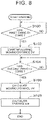
- FIG. 8 is a flowchart showing the flow of a process related to detecting the yaw angle ⁇ according to the first embodiment.
- the process of the flowchart is executed when the vehicle 3 starts parking.
- the ECU 33 determines that parking is started when, for example, operation of a predetermined switch to inform a parking start by the driver is detected.
- the ECU 33 determines that parking is started when, for example, the parking space 5 is detected by using a camera image while the vehicle 3 is backing up.
- the ECU 33 determines that parking is started when, for example, operation of a switch to select the automatic parking function by the driver is detected.
- the ECU 33 (processor 33a) initially determines in step S100 whether the first timing T1 has come.
- the first timing T1 is a timing at which one of the first and second distance measuring sensors 34, 35 begins to face the ground unit 21.
- the first timing T1 can be acquired based on a change of an output signal (the distance D1 or the distance D2) of the first distance measuring sensor 34 or the second distance measuring sensor 35.
- the ECU 33 While the first timing T1 has not come yet in step S100, the ECU 33 repeatedly executes the process of step S100. When the first timing T1 does not come within a predetermined time after the start of the process of step S100, the ECU 33 may cancel the process of detecting the yaw angle ⁇ at the current parking start.
- step S102 the ECU 33 starts measuring the moving distance DV of the vehicle 3, that is, measuring the rotation amount of the rotary shaft of the electric motor 31, with the resolver 36. After that, the process proceeds to step S104.
- step S104 the ECU 33 determines whether the second timing T2 has come.
- the second timing T2 is a timing at which the distance measuring sensor different from the one of the first and second distance measuring sensors 34, 35, which has begun to face the ground unit 21 at the first timing T1, begins to face the ground unit 21.
- the second timing T2, as well as the first timing T1 can be acquired based on a change of an output signal (the distance D1 or the distance D2) of the first distance measuring sensor 34 or the second distance measuring sensor 35.
- step S104 While the second timing T2 has not come yet in step S104, the ECU 33 repeatedly executes the process of step S104.
- the ECU 33 may cancel the process of detecting the yaw angle ⁇ at the current parking start.
- step S106 the ECU 33 calculates a moving distance DV during a period from the first timing T1 to the second timing T2 based on the output signal (more specifically, the measured rotation amount) of the resolver 36. After that, the process proceeds to step S108.
- FIG. 9 is a flowchart showing the flow of a process related to a notification to the driver according to deviation amounts of the relative position and relative rotation angle of the in-vehicle unit 41 with respect to the ground unit 21. The process of the flowchart is also executed when the vehicle 3 starts parking as in the case of FIG. 8 .
- the ECU 33 (processor 33a) initially detects various relative positions (X-axis direction position, Y-axis direction position, and Z-axis direction position) and relative rotation angles (yaw angle ⁇ , roll angle ⁇ , and pitch angle ⁇ ) in step S200.
- the yaw angle ⁇ is detected by the process of the flowchart shown in FIG. 8 .
- the roll angle ⁇ and the pitch angle ⁇ can be detected by a method that will be described in a second embodiment (described later).
- the distance D1 detected by using the first distance measuring sensor 34, the distance D2 detected by using the second distance measuring sensor 35, or an average value of the distance D1 and the distance D2 may be used as the Z-axis direction position.
- the X-axis direction position and the Y-axis direction position can be detected by using any known method.
- step S202 subsequent to step S200 the ECU 33 determines whether each of the various relative positions and relative rotation angles detected in step S200 falls within a predetermined prescribed value (that is, within a range in which noncontact charging can be performed).
- step S204 the ECU 33 executes a process of providing a notification to the driver that the in-vehicle unit 41 falls within the range in which noncontact charging can be performed with respect to the ground unit 21.
- the ECU 33 for example, provides a notification by using a display device 37 installed in an instrument panel of the vehicle 3.
- step S202 determines whether the determination result of step S202 is negative.
- the process proceeds to step S206.
- the ECU 33 for example, executes a process of providing a notification to the driver by using the display device 37 that there is a deviation in at least any one of the relative positions and the relative rotation angles.
- step S208 subsequent to step S206 the ECU 33 determines whether the vehicle 3 has stopped (in other words, whether the driver has stopped parking operation). The determination can be performed based on, for example, whether a change of the rotation angle detected by the resolver 36 has stopped.
- step S208 When the vehicle 3 has not stopped yet in step S208, that is, when parking operation is being performed again, the process returns to step S200. On the other hand, when the vehicle 3 has stopped, the process proceeds to step S210.
- step S210 the ECU 33 executes a process of providing a notification to the driver by using, for example, the display device 37 that noncontact charging is impossible due to a deviation of any one of the relative positions and the relative rotation angles.
- the yaw angle ⁇ of the in-vehicle unit 41 with respect to the ground unit 21 can be detected with the use of a simple configuration made up of the pair of distance measuring sensors 34, 35 and the resolver 36 existing in the vehicle 3.
- the resolver 36 is used to calculate the moving distance DV of the vehicle 3.
- the resolver 36 is a rotation angle sensor for detecting a rotation angle required to control the electric motor 31, so the resolver 36 is existing in the vehicle 3 and is highly accurate. Therefore, the moving distance DV can be accurately calculated without addition of any component.
- the method of detecting the yaw angle ⁇ uses the first and second distance measuring sensors 34, 35 and the resolver 36 and does not need to generate a magnetic field to detect the yaw angle ⁇ .
- the first and second distance measuring sensors 34, 35 and the resolver 36 are independent of the power receiving circuit 42. Therefore, a deviation of the yaw angle ⁇ of the vehicle 3, which can occur due to some reasons, such as being pushed by another vehicle after parking, can be detected during charging. Detecting the roll angle ⁇ and the pitch angle ⁇ with the method described in the next second embodiment can also be performed similarly.
- the first and second distance measuring sensors 34, 35 are able to detect the Z-axis direction position as described in relation to the process of step S200. Therefore, the first and second distance measuring sensors 34, 35 can be used to detect a vehicle height not only at the time of parking but also during charging or another usage. For example, a change in vehicle height can be detected as a result of getting on or off of a person or loading or unloading of baggage. The fact that the vehicle height (relative position in the Z-axis direction) deviates from a prescribed value can be detected by using the first distance measuring sensor 34 or the second distance measuring sensor 35 during charging, and charging can be stopped.
- the power transmission and receiving system 1 for a vehicle includes the following rotation angle detecting apparatus 60 instead of the rotation angle detecting apparatus 50.
- the rotation angle detecting apparatus 60 calculates the roll angle ⁇ and the pitch angle ⁇ in addition to the yaw angle ⁇ described in the first embodiment as the relative rotation angles of the in-vehicle unit 41 with respect to the ground unit 21.
- FIG. 10 is a block diagram showing the configuration of the rotation angle detecting apparatus 60 according to the second embodiment.
- the rotation angle detecting apparatus 60 includes third and fourth distance measuring sensors 38, 39 in addition to the ECU 33, the first and second distance measuring sensors 34, 35, and the resolver 36.
- FIG. 11 is a view for illustrating locations where the third and fourth distance measuring sensors 38, 39 shown in FIG. 10 are disposed.
- FIG. 11 is a perspective view of the in-vehicle unit 41 when viewed from the lower side in the vertical direction of the vehicle 3.
- each of the third and fourth distance measuring sensors 38, 39, as well as the distance measuring sensors 34, 35 is installed in the in-vehicle unit 41 so as to face downward in the Z-axis direction, that is, to face the road surface 6.
- the third and fourth distance measuring sensors 38, 39 are mounted on the in-vehicle unit 41 able to face the ground unit 21, the third and fourth distance measuring sensors 38, 39 are able to face the ground unit 21 at the time of parking.
- the third and fourth distance measuring sensors 38, 39 respectively detect a distance D3 and a distance D4 from the road surface 6. More specifically, the first, second, third, and fourth distance measuring sensors 34, 35, 38, 39 are installed at the bottom surface 43a of the case 43 of the in-vehicle unit 41.
- the third distance measuring sensor 38 and the fourth distance measuring sensor 39 are disposed so as to be arranged in the right and left direction (Y-axis direction) of the vehicle 3.
- the third distance measuring sensor 38 is disposed apart from the first distance measuring sensor 34 by a sensor-to-sensor distance DS2 in the front and rear direction (X-axis direction) of the vehicle 3.
- the fourth distance measuring sensor 39 is disposed apart from the second distance measuring sensor 35 by the sensor-to-sensor distance DS2 in the X-axis direction. Therefore, the distance between the third distance measuring sensor 38 and the fourth distance measuring sensor 39 is also the sensor-to-sensor distance DS1.
- the first, second, third, and fourth distance measuring sensors 34, 35, 38, 39 are disposed so as to surround the power receiving coil 44.
- the basic shape of the bottom surface 43a of the case 43 of the in-vehicle unit 41 is a rectangular shape as an example.
- the first, second, third, and fourth distance measuring sensors 34, 35, 38, 39 are disposed at four corners of the bottom surface 43a.
- a method of calculating the roll angle ⁇ and the pitch angle ⁇ according to the second embodiment will be described with reference to FIG. 12A to FIG. 13B .
- a method of calculating the yaw angle ⁇ is similar to that of the first embodiment. In other words, the yaw angle ⁇ is calculated by using the pair of distance measuring sensors 34, 35. The yaw angle ⁇ may be calculated with a similar method by using the pair of distance measuring sensors 38, 39.
- FIG. 12A is a view of the in-vehicle unit 41 when viewed from the rear side of the vehicle 3.
- the in-vehicle unit 41 is located above the ground unit 21 in a state where the right side (right side on the drawing sheet) of the vehicle 3 is inclined downward with respect to the left side.
- the top surface 23a of the ground unit 21 is parallel or substantially parallel to the road surface 6.
- the ECU 33 calculates a first difference A1.
- the first and third distance measuring sensors 34, 38 are on the same straight line parallel to the X-axis.
- the second and fourth distance measuring sensors 35, 39 are also on another same straight line parallel to the X-axis.
- the first difference A1 is a difference between an average value of the distance D1 and the distance D3 and an average value of the distance D2 and the distance D4.
- a right angled triangle as shown in FIG. 12B is determined.
- an interior angle facing a side of which the length is the first difference A1 is equal to an angle formed between the ground-side top surface 23a and the vehicle-side bottom surface 43a when viewed in the X-axis direction, that is, the roll angle ⁇ .
- the length of the hypotenuse of the right angled triangle is equal to the sensor-to-sensor distance DS1. Therefore, an arc sine value of a value obtained by dividing the first difference A1 by the sensor-to-sensor distance DS1 can be calculated as the roll angle ⁇ based on the following expression (2).
- ⁇ arcsin A 1 / DS 1
- FIG. 13A is a view of the in-vehicle unit 41 when viewed from the left side of the vehicle 3.
- the in-vehicle unit 41 is located above the ground unit 21 in a state where the rear side (right side on the drawing sheet) of the vehicle 3 is inclined so as to be lower than the front side.
- the ECU 33 calculates a second difference A2.
- the first and second distance measuring sensors 34, 35 are on the same straight line parallel to the Y-axis.
- the third and fourth distance measuring sensors 38, 39 are also on another same straight line parallel to the Y-axis.
- the second difference A2 is a difference between an average value of the distance D1 and the distance D2 and an average value of the distance D3 and the distance D4.
- a right angled triangle as shown in FIG. 13B is determined.
- an interior angle facing a side of which the length is the second difference A2 is equal to an angle formed between the ground-side top surface 23a and the vehicle-side bottom surface 43a when viewed in the Y-axis direction, that is, the pitch angle ⁇ .
- the length of the hypotenuse of the right angled triangle is equal to the sensor-to-sensor distance DS2. Therefore, an arc sine value of a value obtained by dividing the second difference A2 by the sensor-to-sensor distance DS2 can be calculated as the pitch angle ⁇ based on the following expression (3).
- ⁇ arcsin A 2 / DS 2
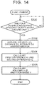
- FIG. 14 is a flowchart showing the flow of a process related to detecting the roll angle ⁇ and the pitch angle ⁇ according to the second embodiment. The process of the flowchart is also executed when the vehicle 3 starts parking as in the case of FIG. 8 .
- the ECU 33 (processor 33a) initially determines in step S300 whether all the four distance measuring sensors 34, 35, 38, 39 are above the ground unit 21. The determination is performed by, for example, comparing each of the distance D1, the distance D2, the distance D3, and the distance D4 with a threshold.
- step S300 While the determination result of step S300 is negative, the ECU 33 repeatedly executes the process of step S300. When the determination result is not affirmative within a predetermined time after the start of the process of step S300, the ECU 33 may cancel the process of detecting the roll angle ⁇ and the pitch angle ⁇ at the current parking start.
- step S302 the ECU 33 acquires the distance D1, the distance D2, the distance D3, and the distance D4. Subsequently, in step S304, the ECU 33 calculates the first difference A1 and the second difference A2 by using the distance D1, the distance D2, the distance D3, and the distance D4 acquired in step S302.
- the rotation angle detecting apparatus 60 additionally includes the pair of distance measuring sensors 38, 39 as compared to the rotation angle detecting apparatus 50 according to the first embodiment in order to detect the roll angle ⁇ and the pitch angle ⁇ .
- the rotation angle detecting apparatus 60 not only the yaw angle ⁇ but also the roll angle ⁇ and the pitch angle ⁇ at the time of parking can be suitably detected with the use of a simple configuration.
- the pair of distance measuring sensors 34, 35 but also the other pair of distance measuring sensors 38, 39 can be used to detect the yaw angle ⁇ .
- one of the distance D1 and the distance D3 may be used.
- an average value of the distance D1 and the distance D3 is used. This also applies to the relationship between the distance D2 and the distance D4.
- the first difference A1 can be calculated while the influence of variations of distances respectively detected by the individual distance measuring sensors is reduced. This also applies to calculation of the second difference A2 in the method of calculating the pitch angle ⁇ .
- the first, second, third, and fourth distance measuring sensors 34, 35, 38, 39 are disposed to surround the power receiving coil 44.
- both the roll angle ⁇ and the pitch angle ⁇ can occur.
- a distance at a location close to the power receiving coil 44 in the front and rear direction of the vehicle 3 can be acquired by using an average value of the distance D1 and the distance D3 as compared to the case where only the distance D1 or the distance D3 is used.
- the rotation angle detecting apparatus 50 and the rotation angle detecting apparatus 60 each are applied to the noncontact power transmission and receiving system 1 for a vehicle.
- the power transmission and receiving system for a vehicle, to which the rotation angle detecting apparatus according to the disclosure is applied may be of a contact type.
- a contact power transmission and receiving system may include, for example, an in-vehicle unit including a vehicle-side connector connected to a ground-side connector, and a ground unit including a robot arm that connects the ground-side connector to the vehicle-side connector.
- the power transmission and receiving system for a vehicle may be configured such that the in-vehicle unit is a power transmission unit and the ground unit is a power receiving unit, opposite to the example of the power transmission and receiving system 1 for a vehicle.
Landscapes
- Engineering & Computer Science (AREA)
- Power Engineering (AREA)
- Mechanical Engineering (AREA)
- Transportation (AREA)
- Computer Networks & Wireless Communication (AREA)
- Physics & Mathematics (AREA)
- General Physics & Mathematics (AREA)
- Chemical & Material Sciences (AREA)
- Combustion & Propulsion (AREA)
- Length Measuring Devices With Unspecified Measuring Means (AREA)
- Traffic Control Systems (AREA)
- Arrangement Or Mounting Of Propulsion Units For Vehicles (AREA)
- Charge And Discharge Circuits For Batteries Or The Like (AREA)
- Measurement Of Length, Angles, Or The Like Using Electric Or Magnetic Means (AREA)
Abstract
Description
- The disclosure relates to a rotation angle detecting apparatus that detects a relative rotation angle of an in-vehicle unit with respect to a ground unit, and a power transmission and receiving system for a vehicle.
-
Japanese Unexamined Patent Application Publication No. 2017-200328 JP 2017-200328 A - As described in
JP 2017-200328 A - The disclosure enables detection of a relative rotation angle of an in-vehicle unit with respect to a ground unit with the use of a simple configuration.
- A first aspect of the disclosure relates to a rotation angle detecting apparatus. The rotation angle detecting apparatus detects a relative rotation angle of an in-vehicle unit with respect to a ground unit. The ground unit is one of a power transmission unit and a power receiving unit and is disposed in a parking space. The in-vehicle unit is the other one of the power transmission unit and the power receiving unit and is mounted on a vehicle at a location at which the in-vehicle unit is able to face the ground unit. When the ground unit is viewed from above in a vertical direction, the ground unit has a linear side facing toward the vehicle that approaches the ground unit. The rotation angle detecting apparatus includes a first distance measuring sensor, a second distance measuring sensor, a rotation angle sensor, and a processor. The first distance measuring sensor and the second distance measuring sensor are mounted on the vehicle so as to be arranged in a right and left direction of the vehicle and to face a road surface at a location at which the first distance measuring sensor and the second distance measuring sensor are able to face the ground unit at a time of parking. The rotation angle sensor is configured to detect a rotation angle of a wheel rotary shaft of the vehicle or a rotation angle of a rotary shaft that rotates with the wheel rotary shaft. The processor is configured to, after the vehicle starts parking, acquire a first timing at which one of the first distance measuring sensor and the second distance measuring sensor begins to face the ground unit based on a change of an output signal of the one of the first distance measuring sensor and the second distance measuring sensor. The processor is configured to, after the first timing is detected, acquire a second timing at which the other one of the first distance measuring sensor and the second distance measuring sensor begins to face the ground unit, based on a change of an output signal of the other one of the first distance measuring sensor and the second distance measuring sensor. The processor is configured to calculate a moving distance of the vehicle during a period from the first timing to the second timing based on an output signal of the rotation angle sensor. The processor is configured to calculate an arc tangent value of a value obtained by dividing the calculated moving distance by a distance between the first distance measuring sensor and the second distance measuring sensor as a yaw angle. The yaw angle is a rotation angle of the in-vehicle unit with respect to the ground unit about a vertical axis of the vehicle.
- The first distance measuring sensor and the second distance measuring sensor may be installed in the in-vehicle unit.
- The rotation angle detecting apparatus may further include a third distance measuring sensor and a fourth distance measuring sensor arranged in the right and left direction and installed in the in-vehicle unit so as to face a road surface. The third distance measuring sensor may be disposed apart from the first distance measuring sensor by a predetermined distance in a front and rear direction of the vehicle. The fourth distance measuring sensor may be disposed apart from the second distance measuring sensor by the predetermined distance in the front and rear direction.
- The processor may be configured to calculate a first difference between an average value of a first distance detected by the first distance measuring sensor and a third distance detected by the third distance measuring sensor and an average value of a second distance detected by the second distance measuring sensor and a fourth distance detected by the fourth distance measuring sensor. The processor may be configured to calculate an arc sine value of a value obtained by dividing the calculated first difference by the distance between the first distance measuring sensor and the second distance measuring sensor as a roll angle that is a rotation angle of the in-vehicle unit with respect to the ground unit about a longitudinal axis of the vehicle.
- The processor may be configured to calculate a second difference between an average value of a first distance detected by the first distance measuring sensor and a second distance detected by the second distance measuring sensor and an average value of a third distance detected by the third distance measuring sensor and a fourth distance detected by the fourth distance measuring sensor. The processor may be configured to calculate an arc sine value of a value obtained by dividing the calculated second difference by a distance between the first distance measuring sensor and the third distance measuring sensor as a pitch angle that is a rotation angle of the in-vehicle unit with respect to the ground unit about a transverse axis of the vehicle.
- The in-vehicle unit may include a power transmission coil or a power receiving coil for transmitting or receiving electric power to or from the ground unit in a noncontact manner. When the in-vehicle unit is viewed in a direction of the vertical axis, the first distance measuring sensor, the second distance measuring sensor, the third distance measuring sensor, and the fourth distance measuring sensor may be disposed so as to surround the power transmission coil or the power receiving coil disposed in the in-vehicle unit.
- The rotation angle sensor may be a resolver configured to detect a rotation angle of a rotary shaft of an electric motor that drives the vehicle.
- A second aspect of the disclosure relates to a power transmission and receiving system for a vehicle. The power transmission and reception system includes the rotation angle detecting apparatus. The power transmission and receiving system may be configured to transmit or receive electric power between the power transmission unit and the power receiving unit in a noncontact manner.
- With the rotation angle detecting apparatus and the power transmission and receiving system including the rotation angle detecting apparatus according to the aspects of the disclosure, the yaw angle of the in-vehicle unit with respect to the ground unit can be detected with the use of a simple configuration made up of a pair of distance measuring sensors (the first and second distance measuring sensors) and the rotation angle sensor of the vehicle.
- Features, advantages, and technical and industrial significance of exemplary embodiments of the invention will be described below with reference to the accompanying drawings, in which like signs denote like elements, and wherein:
-
FIG. 1 is a diagram schematically showing an example of the configuration of a power transmission and receiving system for a vehicle, to which a rotation angle detecting apparatus according to a first embodiment is applied; -
FIG. 2 is a view from above a vehicle approaching a parking space in a vertical direction (Z-axis direction); -
FIG. 3A is a view for illustrating the definition of a yaw angle of an in-vehicle unit with respect to a ground unit; -
FIG. 3B is a view for illustrating the definition of a yaw angle of an in-vehicle unit with respect to a ground unit; -
FIG. 4 is a block diagram showing the configuration of the rotation angle detecting apparatus according to the first embodiment; -
FIG. 5 is a perspective view of the in-vehicle unit shown inFIG. 1 when viewed from a lower side in the vertical direction of the vehicle; -
FIG. 6A is a view for illustrating the outline of a method of calculating a yaw angle according to the first embodiment; -
FIG. 6B is a view for illustrating the outline of a method of calculating a yaw angle according to the first embodiment; -
FIG. 7 is a view for illustrating the outline of a method of calculating a yaw angle according to the first embodiment; -
FIG. 8 is a flowchart showing the flow of a process related to detecting a yaw angle according to the first embodiment; -
FIG. 9 is a flowchart showing the flow of a process related to a notification to a driver according to deviation amounts of a relative position and relative rotation angle of the in-vehicle unit with respect to the ground unit; -
FIG. 10 is a block diagram showing the configuration of a rotation angle detecting apparatus according to a second embodiment; -
FIG. 11 is a view for illustrating locations where third and fourth distance measuring sensors shown inFIG. 10 are disposed; -
FIG. 12A is a view for illustrating a method of calculating a roll angle according to the second Embodiment; -
FIG. 12B is a view for illustrating a method of calculating a roll angle according to the second Embodiment; -
FIG. 13A is a view for illustrating a method of calculating a pitch angle according to the second embodiment; -
FIG. 13B is a view for illustrating a method of calculating a pitch angle according to the second embodiment; and -
FIG. 14 is a flowchart showing the flow of a process related to detecting a roll angle and a pitch angle according to the second embodiment. - In the following embodiments, when the number, count, amount, or range of each element is referred to, the technical idea according to the disclosure is not limited thereto unless otherwise specified or apparently determined to that in principle. The structures, steps, and the like, that will be described in the following embodiments, are not always indispensable to the technical idea according to the disclosure unless otherwise specified or apparently determined to them in principle.
-
FIG. 1 is a diagram schematically showing an example of the configuration of a power transmission and receivingsystem 1 for a vehicle, to which a rotationangle detecting apparatus 50 according to a first embodiment is applied. The power transmission and receivingsystem 1 includes apower transmission apparatus 2 installed at a ground side, and a power receiving apparatus 4 mounted on avehicle 3. The power transmission and receivingsystem 1 is configured to transfer electric power from thepower transmission apparatus 2 to the power receiving apparatus 4 by using, for example, a magnetic field resonance system. However, a noncontact power transfer system is not limited, and another system, such as an electromagnetic induction system, may be used. - The
power transmission apparatus 2 is installed in aparking space 5 of thevehicle 3. Thepower transmission apparatus 2 includes a power transmission unit (hereinafter, also referred to as ground unit) 21. Thepower transmission apparatus 2 is made up of theground unit 21 and apower transmission station 22 as an example. - The
ground unit 21 includes acase 23. Thecase 23 accommodates apower transmission coil 24. Thepower transmission station 22 is electrically connected to theground unit 21. Thepower transmission station 22 includes an alternatingcurrent power supply 25 and apower transmission circuit 26. The alternatingcurrent power supply 25 supplies electric power to the ground unit 21 (power transmission coil 24) via thepower transmission circuit 26. Thepower transmission circuit 26 includes an inverter and controls a current flowing through thepower transmission coil 24. - As shown in
FIG. 1 , theground unit 21 is placed on aroad surface 6 and has astep 27 between atop surface 23a and theroad surface 6. The height of thestep 27 is less than the clearance between theroad surface 6 and the bottom surface of thevehicle 3. Theground unit 21 just needs to be disposed on theroad surface 6 so as to have thestep 27 that can be detected by first and seconddistance measuring sensors 34, 35 (described later) and may also be, for example, embedded in theroad surface 6. Thestep 27 may be formed such that thetop surface 23a is lower than theroad surface 6 instead of an example in which thetop surface 23a is higher than theroad surface 6 as shown inFIG. 1 . Thepower transmission station 22 is installed at, for example, one end of theparking space 5. - The power receiving apparatus 4 mounted on the
vehicle 3 includes a power receiving unit (hereinafter, also referred to as in-vehicle unit) 41. The power receiving apparatus 4 is made up of the in-vehicle unit 41 and apower receiving circuit 42 as an example. The in-vehicle unit 41 is mounted on thevehicle 3 at a location at which the in-vehicle unit 41 is able to face the ground unit 21 (that is, the bottom of the vehicle 3). The in-vehicle unit 41 receives electric power transferred from the ground unit (power transmission unit) 21. - The in-
vehicle unit 41 includes acase 43. Thecase 43 accommodates apower receiving coil 44. Thepower receiving coil 44 receives electric power transferred from thepower transmission coil 24 in a noncontact manner in a state of facing thepower transmission coil 24. Thepower receiving circuit 42 includes a rectifier that converts alternating-current power received by thepower receiving coil 44 to direct-current power by rectifying the alternating-current power. - The
vehicle 3 includes anelectric motor 31 serving as a driving source, and abattery 32 that supplies electric power to theelectric motor 31 in addition to the power receiving apparatus 4. In other words, thevehicle 3 is an electrically-powered vehicle. Specifically, thevehicle 3 is, for example, a battery electric vehicle. Other examples of thevehicle 3 include a hybrid vehicle including an internal combustion engine together with theelectric motor 31 as a driving source, and a fuel cell electric vehicle. Thebattery 32 is, for example, a lithium ion battery and is connected to thepower receiving circuit 42. Thebattery 32 is charged with electric power supplied from the ground-sidepower transmission apparatus 2 via the power receiving apparatus 4. - The
vehicle 3 includes an electronic control unit (ECU) 33. TheECU 33 is a computer that executes various processes related to thevehicle 3. Specifically, the processes to be executed by theECU 33 include a process related to control over theelectric motor 31, a process related to control over electric power received from thepower transmission apparatus 2, and a process related to detecting various rotation angles (yaw angle α in the first embodiment) (described later). TheECU 33 includes aprocessor 33a and astorage device 33b. Theprocessor 33a reads out a program stored in thestorage device 33b and runs the program. Thus, the above-described various processes are implemented by theprocessor 33a. A plurality of theECUs 33 may be provided. For example, the process related to detecting a yaw angle α may be executed by a dedicated ECU (processor). - The
vehicle 3 includes the pair of distance measuring sensors (first and second distance measuring sensors) 34, 35 and aresolver 36 in order to detect a yaw angle α. The details of thedistance measuring sensors FIG. 5 . - The
resolver 36 detects the rotation angle of the rotary shaft of theelectric motor 31. The rotary shaft of theelectric motor 31 may be regarded as an example of a rotary shaft that rotates in synchronization with the rotary shafts ofwheels 7 of thevehicle 3. Therefore, theECU 33 is capable of calculating a moving distance of thevehicle 3 based on the rotation angle of the electric motor 31 (more specifically, the rotation angle, a gear ratio between theelectric motor 31 and eachwheel 7, and the radius of each wheel 7 (tire)). Theresolver 36 may be regarded as an example of a rotation angle sensor according to the disclosure. The rotation angle sensor may be, for example, a wheel speed sensor that detects the rotation angle of the rotary shaft of any one of thewheels 7 instead of theresolver 36. In addition, theresolver 36 used to detect a rotation angle required to control theelectric motor 31 is generally capable of detecting a rotation angle with high accuracy as compared to a wheel speed sensor. -
FIG. 2 is a view from above thevehicle 3 approaching theparking space 5 in the vertical direction (Z-axis direction). Thereference sign 8 indicates a parking lot line that defines theparking space 5. A longitudinal axis, a transverse axis, and a vertical axis of thevehicle 3 are respectively referred to as X-axis, Y-axis, and Z-axis (seeFIG. 2 andFIG. 5 and the like (described later)). More specifically,FIG. 2 shows back end parking as an example; however, a method of calculating a yaw angle α, which will be described below, is also applicable to front end parking. - In a system that performs noncontact charging as in the case of the power transmission and receiving
system 1, the relative position and relative rotation angle of the in-vehicle unit with respect to the ground unit are required to be accurately detected at the time of transmitting and receiving electric power in a noncontact manner. This is to determine whether each of the relative position and the relative rotation angle falls within a range in which noncontact charging is possible. Specifically, the relative position includes an X-axis direction position, a Y-axis direction position, and a Z-axis direction position, and the relative rotation angle includes a yaw angle α (a rotation angle about the Z-axis), a roll angle β (a rotation angle about the X-axis), and a pitch angle γ (a rotation angle about the Y-axis). - The definition of the yaw angle α of the in-
vehicle unit 41 with respect to theground unit 21 will be described with reference toFIG. 3A and FIG. 3B. FIG. 3A and FIG. 3B are also views of theground unit 21 and the in-vehicle unit 41 when viewed in the Z-axis direction as in the case ofFIG. 2 . When thevehicle 3 is properly parked in theparking space 5 as represented by the dashed line inFIG. 2 , the longitudinal axis (X-axis) of thevehicle 3 is parallel to theparking lot line 8. Here, to determine the yaw angle α of the in-vehicle unit 41 with respect to theground unit 21, an axis parallel to theparking lot line 8 in an XY-plane is used as a reference axis L1 of theground unit 21. An axis parallel to the X-axis (longitudinal axis) of thevehicle 3 is used as a reference axis L2 of the in-vehicle unit 41. - In the example shown in
FIG. 3A , thevehicle 3 is parked in a state where the longitudinal axis (X-axis) is parallel to theparking lot line 8. In this case, the reference axis L1 and the reference axis L2 are parallel to each other, so the yaw angle α is zero. On the other hand, in the example shown inFIG. 3B , the reference axis L2 is inclined with respect to the reference axis L1. Therefore, the inclination angle of the reference axis L2 with respect to the reference axis L1 is determined as the yaw angle α. - In the present embodiment, a method of detecting the yaw angle α of the relative position and relative rotation angle will be described.
FIG. 4 is a block diagram showing the configuration of the rotationangle detecting apparatus 50 according to the first embodiment. The rotationangle detecting apparatus 50 is made up of theECU 33, the first and seconddistance measuring sensors resolver 36. -
FIG. 5 is a perspective view of the in-vehicle unit 41 shown inFIG. 1 when viewed from the lower side of thevehicle 3 in the vertical direction. Abottom surface 43a of thecase 43 of the in-vehicle unit 41 faces theroad surface 6 or theground unit 21. As shown inFIG. 5 , the in-vehicle unit 41 is mounted on thevehicle 3 such that thebottom surface 43a is parallel to the XY-plane. - The first
distance measuring sensor 34 is installed in the in-vehicle unit 41 so as to face downward in the Z-axis direction, that is, so as to face theroad surface 6 and detects a distance D1 to theroad surface 6. The seconddistance measuring sensor 35 is installed in the in-vehicle unit 41 so as to face downward in the Z-axis direction, that is, so as to face theroad surface 6 and detects a distance D2 to theroad surface 6. The firstdistance measuring sensor 34 and the seconddistance measuring sensor 35 are disposed so as to be arranged in a right and left direction (Y-axis direction) of thevehicle 3. - More specifically, the distance between the first
distance measuring sensor 34 and the second distance measuring sensor 35 (hereinafter, referred to as sensor-to-sensor distance DS1) is set so as to be shorter than the width of theground unit 21 in a direction perpendicular to the reference axis L1. Thus, except when thevehicle 3 is parked so as to significantly deviate in the direction perpendicular to the reference axis L1 with respect to theground unit 21, each of thedistance measuring sensors road surface 6 at a location at which each of thedistance measuring sensors ground unit 21 at the time of parking. - As the first
distance measuring sensor 34 reaches just above theground unit 21 at the time of parking, the distance D1 detected by the firstdistance measuring sensor 34 changes from a distance from theroad surface 6 to a distance from theground unit 21. Therefore, by measuring the distance D1 with the firstdistance measuring sensor 34 during parking, the timing at which the firstdistance measuring sensor 34 begins to face theground unit 21 can be detected. In other words, thestep 27 can be detected. This also applies to the seconddistance measuring sensor 35. - In the example shown in
FIG. 5 , the first and seconddistance measuring sensors vehicle unit 41. However, as long as the first and seconddistance measuring sensors vehicle 3 so as to face theroad surface 6 at locations at which the first and seconddistance measuring sensors ground unit 21 at the time of parking, the first and seconddistance measuring sensors vehicle 3 in an area other than the in-vehicle unit 41. In addition, as shown inFIG. 3A and FIG. 3B , when viewed from above in the Z-axis direction, the dimensions of the in-vehicle unit 41 in the direction of the reference axis L1 and the direction perpendicular to the reference axis L1 are respectively shorter than the dimensions of theground unit 21 as an example. -
FIG. 6A, FIG. 6B , andFIG. 7 are views for illustrating the outline of a method of calculating a yaw angle α according to the first embodiment. The drawings are also views of theground unit 21 and the in-vehicle unit 41 when viewed in the Z-axis direction. The drawings show the vehicle being parked in a state where the vehicle-side reference axis L2 is inclined with respect to the ground-side reference axis L1. - The shape of the
case 23 of theground unit 21, which is a precondition to calculate a yaw angle α, will be described. As shown inFIG. 6A and FIG. 6B , the basic shape of thecase 23 is a rectangular shape as an example. On this precondition, to calculate the yaw angle α, aside 21a of thecase 23, facing toward the vehicle 3 (in-vehicle unit 41) that approaches theground unit 21, has a linear shape. More specifically, theside 21a has a linear shape extending in the direction perpendicular to the reference axis L1. - In relation to calculation of the yaw angle α, the linear shape of the
side 21a is not necessarily limited to an example having a strict linear shape and is a concept including an example having a substantially linear shape. In an example of a parking space in which thevehicle 3 is able to approach theground unit 21 to park from both sides of the reference axis L1, to detect the yaw angle α at the time of parking from both sides, thecase 23 of theground unit 21 installed in the parking space may have a side opposite to theside 21a and having a linear shape as well as theside 21a. As long as thecase 23 has alinear side 21a described here, thecase 23 may have any basic shape other than a rectangular shape. -
FIG. 6A corresponds to a first timing T1 at which the seconddistance measuring sensor 35 begins to face theground unit 21. The first timing T1 can be detected based on a change of the distance D2 resulting from passage of the seconddistance measuring sensor 35 through theside 21a (the step 27). As thevehicle 3 continues moving after the first timing T1, a second timing T2 at which the firstdistance measuring sensor 34 begins to face theground unit 21 as shown inFIG. 6B comes. The second timing T2 can be detected based on a change of the distance D1 resulting from passage of the firstdistance measuring sensor 34 through theside 21a (the step 27). -
FIG. 7 is a view showing the relationship between the location of each of the first and seconddistance measuring sensors FIG. 6A and FIG. 6B and the location of the ground unit 21 (theside 21a). TheECU 33 is able to calculate a moving distance DV of thevehicle 3 during a period from the first timing T1 to the second timing T2 based on the output signal of theresolver 36. The sensor-to-sensor distance DS1 is a known value. The direction of a straight line connecting the first and seconddistance measuring sensors 34, 35 (that is, the Y-axis direction) and a traveling direction (that is, the X-axis direction) of thevehicle 3 are perpendicular to each other. - Therefore, as represented by the wide line in
FIG. 7 , a right angled triangle having a side of which the length is the sensor-to-sensor distance DS1 and a side of which the length is the moving distance DV together with a hypotenuse can be determined. In the right angled triangle, an interior angle opposite to the side of which the length is the moving distance DV is equal to an angle formed between the ground-side reference axis L1 and the vehicle-side reference axis L2, that is, the yaw angle α. Therefore, an arc tangent value of a value obtained by dividing the moving distance DV by the sensor-to-sensor distance DS1 can be calculated as the yaw angle α based on the following expression (1).
-
FIG. 8 is a flowchart showing the flow of a process related to detecting the yaw angle α according to the first embodiment. The process of the flowchart is executed when thevehicle 3 starts parking. Specifically, in an example in which thevehicle 3 is parked by driver's operation, theECU 33 determines that parking is started when, for example, operation of a predetermined switch to inform a parking start by the driver is detected. Alternatively, theECU 33 determines that parking is started when, for example, theparking space 5 is detected by using a camera image while thevehicle 3 is backing up. In an example in which thevehicle 3 has an automatic parking function, theECU 33 determines that parking is started when, for example, operation of a switch to select the automatic parking function by the driver is detected. - In
FIG. 8 , the ECU 33 (processor 33a) initially determines in step S100 whether the first timing T1 has come. The first timing T1 is a timing at which one of the first and seconddistance measuring sensors ground unit 21. As described above, the first timing T1 can be acquired based on a change of an output signal (the distance D1 or the distance D2) of the firstdistance measuring sensor 34 or the seconddistance measuring sensor 35. - While the first timing T1 has not come yet in step S100, the
ECU 33 repeatedly executes the process of step S100. When the first timing T1 does not come within a predetermined time after the start of the process of step S100, theECU 33 may cancel the process of detecting the yaw angle α at the current parking start. - On the other hand, when the first timing T1 has come in step S100, the process proceeds to step S102. In step S102, the
ECU 33 starts measuring the moving distance DV of thevehicle 3, that is, measuring the rotation amount of the rotary shaft of theelectric motor 31, with theresolver 36. After that, the process proceeds to step S104. - In step S104, the
ECU 33 determines whether the second timing T2 has come. The second timing T2 is a timing at which the distance measuring sensor different from the one of the first and seconddistance measuring sensors ground unit 21 at the first timing T1, begins to face theground unit 21. The second timing T2, as well as the first timing T1, can be acquired based on a change of an output signal (the distance D1 or the distance D2) of the firstdistance measuring sensor 34 or the seconddistance measuring sensor 35. - While the second timing T2 has not come yet in step S104, the
ECU 33 repeatedly executes the process of step S104. When the second timing T2 does not come within a predetermined time after the start of the process of step S104, theECU 33 may cancel the process of detecting the yaw angle α at the current parking start. - On the other hand, when the second timing T2 has come in step S104, the process proceeds to step S106. In step S106, the
ECU 33 calculates a moving distance DV during a period from the first timing T1 to the second timing T2 based on the output signal (more specifically, the measured rotation amount) of theresolver 36. After that, the process proceeds to step S108. - In step S108, the
ECU 33 calculates an arc tangent value (= arctan(DV/DS1)) of a value obtained by dividing the moving distance DV calculated in step S106 by the known sensor-to-sensor distance DS1 as the yaw angle α. -
FIG. 9 is a flowchart showing the flow of a process related to a notification to the driver according to deviation amounts of the relative position and relative rotation angle of the in-vehicle unit 41 with respect to theground unit 21. The process of the flowchart is also executed when thevehicle 3 starts parking as in the case ofFIG. 8 . - In
FIG. 9 , the ECU 33 (processor 33a) initially detects various relative positions (X-axis direction position, Y-axis direction position, and Z-axis direction position) and relative rotation angles (yaw angle α, roll angle β, and pitch angle γ) in step S200. Specifically, the yaw angle α is detected by the process of the flowchart shown inFIG. 8 . The roll angle β and the pitch angle γ can be detected by a method that will be described in a second embodiment (described later). For example, the distance D1 detected by using the firstdistance measuring sensor 34, the distance D2 detected by using the seconddistance measuring sensor 35, or an average value of the distance D1 and the distance D2 may be used as the Z-axis direction position. The X-axis direction position and the Y-axis direction position can be detected by using any known method. - In step S202 subsequent to step S200, the
ECU 33 determines whether each of the various relative positions and relative rotation angles detected in step S200 falls within a predetermined prescribed value (that is, within a range in which noncontact charging can be performed). - When the determination result of step S202 is affirmative, the process proceeds to step S204. In step S204, the
ECU 33 executes a process of providing a notification to the driver that the in-vehicle unit 41 falls within the range in which noncontact charging can be performed with respect to theground unit 21. Specifically, theECU 33, for example, provides a notification by using adisplay device 37 installed in an instrument panel of thevehicle 3. - On the other hand, when the determination result of step S202 is negative, the process proceeds to step S206. In step S206, the
ECU 33, for example, executes a process of providing a notification to the driver by using thedisplay device 37 that there is a deviation in at least any one of the relative positions and the relative rotation angles. - In step S208 subsequent to step S206, the
ECU 33 determines whether thevehicle 3 has stopped (in other words, whether the driver has stopped parking operation). The determination can be performed based on, for example, whether a change of the rotation angle detected by theresolver 36 has stopped. - When the
vehicle 3 has not stopped yet in step S208, that is, when parking operation is being performed again, the process returns to step S200. On the other hand, when thevehicle 3 has stopped, the process proceeds to step S210. In step S210, theECU 33 executes a process of providing a notification to the driver by using, for example, thedisplay device 37 that noncontact charging is impossible due to a deviation of any one of the relative positions and the relative rotation angles. - With the rotation
angle detecting apparatus 50 according to the first embodiment, the yaw angle α of the in-vehicle unit 41 with respect to theground unit 21 can be detected with the use of a simple configuration made up of the pair ofdistance measuring sensors resolver 36 existing in thevehicle 3. - The
resolver 36 is used to calculate the moving distance DV of thevehicle 3. Theresolver 36 is a rotation angle sensor for detecting a rotation angle required to control theelectric motor 31, so theresolver 36 is existing in thevehicle 3 and is highly accurate. Therefore, the moving distance DV can be accurately calculated without addition of any component. - In addition, the method of detecting the yaw angle α according to the present embodiment uses the first and second
distance measuring sensors resolver 36 and does not need to generate a magnetic field to detect the yaw angle α. The first and seconddistance measuring sensors resolver 36 are independent of thepower receiving circuit 42. Therefore, a deviation of the yaw angle α of thevehicle 3, which can occur due to some reasons, such as being pushed by another vehicle after parking, can be detected during charging. Detecting the roll angle β and the pitch angle γ with the method described in the next second embodiment can also be performed similarly. - The first and second
distance measuring sensors distance measuring sensors distance measuring sensor 34 or the seconddistance measuring sensor 35 during charging, and charging can be stopped. - In the second embodiment, the power transmission and receiving
system 1 for a vehicle includes the following rotationangle detecting apparatus 60 instead of the rotationangle detecting apparatus 50. The rotationangle detecting apparatus 60 calculates the roll angle β and the pitch angle γ in addition to the yaw angle α described in the first embodiment as the relative rotation angles of the in-vehicle unit 41 with respect to theground unit 21. -
FIG. 10 is a block diagram showing the configuration of the rotationangle detecting apparatus 60 according to the second embodiment. The rotationangle detecting apparatus 60 includes third and fourthdistance measuring sensors ECU 33, the first and seconddistance measuring sensors resolver 36. -
FIG. 11 is a view for illustrating locations where the third and fourthdistance measuring sensors FIG. 10 are disposed.FIG. 11 is a perspective view of the in-vehicle unit 41 when viewed from the lower side in the vertical direction of thevehicle 3. - The disposition of the first and second
distance measuring sensors distance measuring sensors distance measuring sensors vehicle unit 41 so as to face downward in the Z-axis direction, that is, to face theroad surface 6. In other words, since the third and fourthdistance measuring sensors vehicle unit 41 able to face theground unit 21, the third and fourthdistance measuring sensors ground unit 21 at the time of parking. The third and fourthdistance measuring sensors road surface 6. More specifically, the first, second, third, and fourthdistance measuring sensors bottom surface 43a of thecase 43 of the in-vehicle unit 41. - The third
distance measuring sensor 38 and the fourthdistance measuring sensor 39 are disposed so as to be arranged in the right and left direction (Y-axis direction) of thevehicle 3. The thirddistance measuring sensor 38 is disposed apart from the firstdistance measuring sensor 34 by a sensor-to-sensor distance DS2 in the front and rear direction (X-axis direction) of thevehicle 3. Similarly, the fourthdistance measuring sensor 39 is disposed apart from the seconddistance measuring sensor 35 by the sensor-to-sensor distance DS2 in the X-axis direction. Therefore, the distance between the thirddistance measuring sensor 38 and the fourthdistance measuring sensor 39 is also the sensor-to-sensor distance DS1. - Next, a specific disposition relation among the first, second, third, and fourth
distance measuring sensors power receiving coil 44 in the example shown inFIG. 11 will be described. As shown inFIG. 11 , when the in-vehicle unit 41 is viewed in the direction of the vertical axis (Z-axis) of thevehicle 3, the first, second, third, and fourthdistance measuring sensors power receiving coil 44. In addition, the basic shape of thebottom surface 43a of thecase 43 of the in-vehicle unit 41 is a rectangular shape as an example. The first, second, third, and fourthdistance measuring sensors bottom surface 43a. - A method of calculating the roll angle β and the pitch angle γ according to the second embodiment will be described with reference to
FIG. 12A to FIG. 13B . A method of calculating the yaw angle α is similar to that of the first embodiment. In other words, the yaw angle α is calculated by using the pair ofdistance measuring sensors distance measuring sensors - Initially, a method of calculating the roll angle β will be described.
FIG. 12A is a view of the in-vehicle unit 41 when viewed from the rear side of thevehicle 3. In one example shown inFIG. 12A , the in-vehicle unit 41 is located above theground unit 21 in a state where the right side (right side on the drawing sheet) of thevehicle 3 is inclined downward with respect to the left side. Thetop surface 23a of theground unit 21 is parallel or substantially parallel to theroad surface 6. - To calculate the roll angle β, the
ECU 33 calculates a first difference A1. The first and thirddistance measuring sensors distance measuring sensors - When the first difference A1 is obtained, a right angled triangle as shown in
FIG. 12B is determined. In the right angled triangle, an interior angle facing a side of which the length is the first difference A1 is equal to an angle formed between the ground-sidetop surface 23a and the vehicle-side bottom surface 43a when viewed in the X-axis direction, that is, the roll angle β. The length of the hypotenuse of the right angled triangle is equal to the sensor-to-sensor distance DS1. Therefore, an arc sine value of a value obtained by dividing the first difference A1 by the sensor-to-sensor distance DS1 can be calculated as the roll angle β based on the following expression (2).
- Next, a method of calculating the pitch angle γ will be described.
FIG. 13A is a view of the in-vehicle unit 41 when viewed from the left side of thevehicle 3. In one example shown inFIG. 13A , the in-vehicle unit 41 is located above theground unit 21 in a state where the rear side (right side on the drawing sheet) of thevehicle 3 is inclined so as to be lower than the front side. - To calculate the pitch angle γ, the
ECU 33 calculates a second difference A2. The first and seconddistance measuring sensors distance measuring sensors - When the second difference A2 is obtained, a right angled triangle as shown in
FIG. 13B is determined. In the right angled triangle, an interior angle facing a side of which the length is the second difference A2 is equal to an angle formed between the ground-sidetop surface 23a and the vehicle-side bottom surface 43a when viewed in the Y-axis direction, that is, the pitch angle γ. The length of the hypotenuse of the right angled triangle is equal to the sensor-to-sensor distance DS2. Therefore, an arc sine value of a value obtained by dividing the second difference A2 by the sensor-to-sensor distance DS2 can be calculated as the pitch angle γ based on the following expression (3).
-
FIG. 14 is a flowchart showing the flow of a process related to detecting the roll angle β and the pitch angle γ according to the second embodiment. The process of the flowchart is also executed when thevehicle 3 starts parking as in the case ofFIG. 8 . - In
FIG. 14 , the ECU 33 (processor 33a) initially determines in step S300 whether all the fourdistance measuring sensors ground unit 21. The determination is performed by, for example, comparing each of the distance D1, the distance D2, the distance D3, and the distance D4 with a threshold. - While the determination result of step S300 is negative, the
ECU 33 repeatedly executes the process of step S300. When the determination result is not affirmative within a predetermined time after the start of the process of step S300, theECU 33 may cancel the process of detecting the roll angle β and the pitch angle γ at the current parking start. - On the other hand, when the determination result of step S300 is affirmative, the process proceeds to step S302. In step S302, the
ECU 33 acquires the distance D1, the distance D2, the distance D3, and the distance D4. Subsequently, in step S304, theECU 33 calculates the first difference A1 and the second difference A2 by using the distance D1, the distance D2, the distance D3, and the distance D4 acquired in step S302. - In step S306 subsequent to step S304, the
ECU 33 calculates an arc sine value (= arcsin(A1/DS1)) of a value obtained by dividing the first difference A1 calculated in step S304 by the known sensor-to-sensor distance DS1 as the roll angle β. TheECU 33 calculates an arc sine value (= arcsin(A2/DS2)) of a value obtained by dividing the second difference A2 calculated in step S304 by the known sensor-to-sensor distance DS2 as the pitch angle γ. - The rotation
angle detecting apparatus 60 according to the second embodiment described above additionally includes the pair ofdistance measuring sensors angle detecting apparatus 50 according to the first embodiment in order to detect the roll angle β and the pitch angle γ. In this way, with the rotationangle detecting apparatus 60, not only the yaw angle α but also the roll angle β and the pitch angle γ at the time of parking can be suitably detected with the use of a simple configuration. Not only the pair ofdistance measuring sensors distance measuring sensors - To calculate the first difference A1, one of the distance D1 and the distance D3 may be used. In terms of this point, in the method of calculating the roll angle β according to the present embodiment, an average value of the distance D1 and the distance D3 is used. This also applies to the relationship between the distance D2 and the distance D4. Thus, the first difference A1 can be calculated while the influence of variations of distances respectively detected by the individual distance measuring sensors is reduced. This also applies to calculation of the second difference A2 in the method of calculating the pitch angle γ.
- When the in-
vehicle unit 41 is viewed in the vertical direction (Z-axis direction) of thevehicle 3, the first, second, third, and fourthdistance measuring sensors power receiving coil 44. Thus, the following advantageous effects are obtained. In other words, at the time of parking, both the roll angle β and the pitch angle γ can occur. In terms of this point, with the disposition of the fourdistance measuring sensors power receiving coil 44 in the front and rear direction of thevehicle 3 can be acquired by using an average value of the distance D1 and the distance D3 as compared to the case where only the distance D1 or the distance D3 is used. In other words, by using the average value, when the pitch angle γ is occurring, the roll angle β at a location close to thepower receiving coil 44 can be detected. This also applies to the use of an average value of the distance D2 and the distance D4. This also applies to detecting the pitch angle γ. - In the first and second embodiments, the rotation
angle detecting apparatus 50 and the rotationangle detecting apparatus 60 each are applied to the noncontact power transmission and receivingsystem 1 for a vehicle. However, the power transmission and receiving system for a vehicle, to which the rotation angle detecting apparatus according to the disclosure is applied, may be of a contact type. Specifically, a contact power transmission and receiving system may include, for example, an in-vehicle unit including a vehicle-side connector connected to a ground-side connector, and a ground unit including a robot arm that connects the ground-side connector to the vehicle-side connector. - The power transmission and receiving system for a vehicle, to which the rotation angle detecting apparatus according to the disclosure is applied, may be configured such that the in-vehicle unit is a power transmission unit and the ground unit is a power receiving unit, opposite to the example of the power transmission and receiving
system 1 for a vehicle.
Claims (9)
- A rotation angle detecting apparatus (50; 60) configured to detect a relative rotation angle of an in-vehicle unit (41) with respect to a ground unit (21),the ground unit (21) being one of a power transmission unit and a power receiving unit and disposed in a parking space (5),the in-vehicle unit (41) being the other one of the power transmission unit and the power receiving unit and mounted on a vehicle (3) at a location at which the in-vehicle unit (41) is able to face the ground unit (21),when the ground unit (21) is viewed from above in a vertical direction, the ground unit (21) having a linear side (21a) facing toward the vehicle (3) that approaches the ground unit (21),the rotation angle detecting apparatus (50; 60) comprising:a first distance measuring sensor (34) and a second distance measuring sensor (35) mounted on the vehicle (3) so as to be arranged in a right and left direction of the vehicle (3) and to face a road surface (6) at a location at which the first distance measuring sensor (34) and the second distance measuring sensor (35) are able to face the ground unit (21) at a time of parking;a rotation angle sensor (36) configured to detect a rotation angle of a wheel rotary shaft of the vehicle (3) or a rotation angle of a rotary shaft that rotates with the wheel rotary shaft; anda processor (33a) configured to:after the vehicle (3) starts parking, acquire a first timing (T1) at which one of the first distance measuring sensor (34) and the second distance measuring sensor (35) begins to face the ground unit (21), based on a change of an output signal of the one of the first distance measuring sensor (34) and the second distance measuring sensor (35),after the first timing (T1) is acquired, acquire a second timing (T2) at which the other one of the first distance measuring sensor (34) and the second distance measuring sensor (35) begins to face the ground unit (21), based on a change of an output signal of the other one of the first distance measuring sensor (34) and the second distance measuring sensor (35),calculate a moving distance of the vehicle (3) during a period from the first timing (T1) to the second timing (T2) based on an output signal of the rotation angle sensor (36), andcalculate an arc tangent value of a value obtained by dividing the calculated moving distance by a distance between the first distance measuring sensor (34) and the second distance measuring sensor (35) as a yaw angle, the yaw angle being a rotation angle of the in-vehicle unit (41) with respect to the ground unit (21) about a vertical axis of the vehicle (3).
- The rotation angle detecting apparatus (50; 60) according to claim 1, wherein the first distance measuring sensor (34) and the second distance measuring sensor (35) are installed in the in-vehicle unit (41).
- The rotation angle detecting apparatus (50; 60) according to claim 2, further comprising a third distance measuring sensor (38) and a fourth distance measuring sensor (39) arranged in the right and left direction and installed in the in-vehicle unit (41) so as to face the road surface (6), wherein:the third distance measuring sensor (38) is disposed apart from the first distance measuring sensor (34) by a predetermined distance in a front and rear direction of the vehicle (3); andthe fourth distance measuring sensor (39) is disposed apart from the second distance measuring sensor (35) by the predetermined distance in the front and rear direction.
- The rotation angle detecting apparatus (50; 60) according to claim 3, wherein:the processor (33a) is configured to calculate a first difference between an average value of a first distance detected by the first distance measuring sensor (34) and a third distance detected by the third distance measuring sensor (38) and an average value of a second distance detected by the second distance measuring sensor (35) and a fourth distance detected by the fourth distance measuring sensor (39); andthe processor (33a) is configured to calculate an arc sine value of a value obtained by dividing the calculated first difference by the distance between the first distance measuring sensor (34) and the second distance measuring sensor (35) as a roll angle that is a rotation angle of the in-vehicle unit (41) with respect to the ground unit (21) about a longitudinal axis of the vehicle (3).
- The rotation angle detecting apparatus (50; 60) according to claim 3 or 4, wherein:the processor (33a) is configured to calculate a second difference between an average value of a first distance detected by the first distance measuring sensor (34) and a second distance detected by the second distance measuring sensor (35) and an average value of a third distance detected by the third distance measuring sensor (38) and a fourth distance detected by the fourth distance measuring sensor (39); andthe processor (33a) is configured to calculate an arc sine value of a value obtained by dividing the calculated second difference by a distance between the first distance measuring sensor (34) and the third distance measuring sensor (38) as a pitch angle that is a rotation angle of the in-vehicle unit (41) with respect to the ground unit (21) about a transverse axis of the vehicle (3).
- The rotation angle detecting apparatus (50; 60) according to claim 4 or 5, wherein:the in-vehicle unit (41) includes a power transmission coil (24) or a power receiving coil (44) configured to transmit or receive electric power to or from the ground unit (21) in a noncontact manner; andwhen the in-vehicle unit (41) is viewed in a direction of the vertical axis, the first distance measuring sensor (34), the second distance measuring sensor (35), the third distance measuring sensor (38), and the fourth distance measuring sensor (39) are disposed so as to surround the power transmission coil (24) or the power receiving coil (44) disposed in the in-vehicle unit (41).
- The rotation angle detecting apparatus (50; 60) according to any of claims 1 to 6, wherein the rotation angle sensor (36) is a resolver configured to detect a rotation angle of a rotary shaft of an electric motor (31) configured to drive the vehicle (3).
- A power transmission and receiving system (1) for a vehicle, the power transmission and receiving system comprising the rotation angle detecting apparatus (50; 60) according to any of claims 1 to 7.
- The power transmission and receiving system (1) according to claim 8, wherein the power transmission and receiving system (1) is configured to transmit or receive electric power between the power transmission unit and the power receiving unit in a noncontact manner.
Applications Claiming Priority (1)
| Application Number | Priority Date | Filing Date | Title |
|---|---|---|---|
| JP2021047450A JP7585911B2 (en) | 2021-03-22 | 2021-03-22 | Rotation angle detection device and vehicle power transmission/reception system |
Publications (3)
| Publication Number | Publication Date |
|---|---|
| EP4070984A2 true EP4070984A2 (en) | 2022-10-12 |
| EP4070984A3 EP4070984A3 (en) | 2022-10-19 |
| EP4070984B1 EP4070984B1 (en) | 2023-10-25 |
Family
ID=80928765
Family Applications (1)
| Application Number | Title | Priority Date | Filing Date |
|---|---|---|---|
| EP22163247.4A Active EP4070984B1 (en) | 2021-03-22 | 2022-03-21 | Rotation angle detecting apparatus and power transmission and receiving system for vehicle |
Country Status (4)
| Country | Link |
|---|---|
| US (1) | US12151576B2 (en) |
| EP (1) | EP4070984B1 (en) |
| JP (1) | JP7585911B2 (en) |
| CN (1) | CN115112078A (en) |
Citations (1)
| Publication number | Priority date | Publication date | Assignee | Title |
|---|---|---|---|---|
| JP2017200328A (en) | 2016-04-27 | 2017-11-02 | 本田技研工業株式会社 | Power receiver, transport apparatus, power transmitter, power transmission/reception system, and control method |
Family Cites Families (20)
| Publication number | Priority date | Publication date | Assignee | Title |
|---|---|---|---|---|
| CA1235782A (en) * | 1984-05-09 | 1988-04-26 | Kazuo Sato | Apparatus for calculating position of vehicle |
| JP2503386B2 (en) * | 1985-03-18 | 1996-06-05 | 株式会社日本自動車部品総合研究所 | Wheel abnormality detection device |
| JP2007240381A (en) * | 2006-03-09 | 2007-09-20 | Nissan Motor Co Ltd | Lane recognition device and lane recognition method |
| JP5139185B2 (en) * | 2008-07-16 | 2013-02-06 | 株式会社日本自動車部品総合研究所 | Road surface monitoring device, suspension control device |
| JP5440621B2 (en) * | 2012-01-18 | 2014-03-12 | 株式会社デンソー | Non-contact power feeding device |
| JP5199495B1 (en) * | 2012-03-29 | 2013-05-15 | パナソニック株式会社 | Vehicle guidance device, vehicle guidance information providing device, and vehicle guidance method |
| EP2712762B1 (en) * | 2012-09-28 | 2021-09-01 | Valeo Siemens eAutomotive Germany GmbH | Positioning system and method for positioning a vehicle |
| CN204439036U (en) * | 2015-01-13 | 2015-07-01 | 北京汽车研究总院有限公司 | The measurement mechanism at vehicle side inclination angle |
| CN205273357U (en) * | 2015-12-10 | 2016-06-01 | 奇瑞汽车股份有限公司 | Automobile body gesture indicating system |
| JP6193419B2 (en) * | 2016-02-29 | 2017-09-06 | 本田技研工業株式会社 | Lawn mower |
| JP2017200330A (en) * | 2016-04-27 | 2017-11-02 | 本田技研工業株式会社 | Power receiver, transport apparatus, power transmitter, power transmission/reception system, and control method |
| WO2017208327A1 (en) * | 2016-05-31 | 2017-12-07 | 三菱電機株式会社 | Optical axis control device for headlights |
| JP6450414B2 (en) * | 2017-03-31 | 2019-01-09 | 本田技研工業株式会社 | Non-contact power transmission system |
| JP6446086B2 (en) * | 2017-03-31 | 2018-12-26 | 本田技研工業株式会社 | Non-contact power transmission system |
| JP6513119B2 (en) * | 2017-03-31 | 2019-05-15 | 本田技研工業株式会社 | Contactless power transmission system |
| US10852737B2 (en) * | 2018-03-22 | 2020-12-01 | Micron Technology, Inc. | Power management, dynamic routing and memory management for autonomous driving vehicles |
| JP2020090254A (en) * | 2018-12-07 | 2020-06-11 | 住友電気工業株式会社 | In-vehicle device, parking control method, computer program, in-vehicle system, and power supply unit |
| JP2021030892A (en) * | 2019-08-23 | 2021-03-01 | トヨタ自動車株式会社 | Vehicle travel control device |
| CN110816355B (en) * | 2019-11-12 | 2021-07-20 | 深圳创维数字技术有限公司 | Vehicle charging method, device, and computer-readable storage medium |
| CN111089562A (en) * | 2019-12-26 | 2020-05-01 | 湖北航天技术研究院总体设计所 | Detection method and system suitable for body posture of special vehicle and special vehicle |
-
2021
- 2021-03-22 JP JP2021047450A patent/JP7585911B2/en active Active
-
2022
- 2022-03-15 US US17/694,886 patent/US12151576B2/en active Active
- 2022-03-18 CN CN202210268950.7A patent/CN115112078A/en active Pending
- 2022-03-21 EP EP22163247.4A patent/EP4070984B1/en active Active
Patent Citations (1)
| Publication number | Priority date | Publication date | Assignee | Title |
|---|---|---|---|---|
| JP2017200328A (en) | 2016-04-27 | 2017-11-02 | 本田技研工業株式会社 | Power receiver, transport apparatus, power transmitter, power transmission/reception system, and control method |
Also Published As
| Publication number | Publication date |
|---|---|
| JP2022146472A (en) | 2022-10-05 |
| JP7585911B2 (en) | 2024-11-19 |
| EP4070984B1 (en) | 2023-10-25 |
| EP4070984A3 (en) | 2022-10-19 |
| US12151576B2 (en) | 2024-11-26 |
| CN115112078A (en) | 2022-09-27 |
| US20220297562A1 (en) | 2022-09-22 |
Similar Documents
| Publication | Publication Date | Title |
|---|---|---|
| US9463706B2 (en) | Infrared triangulation method for locating vehicles for hands-free electric vehicle charging | |
| CN108749594B (en) | Contactless Power Transmission System | |
| US9477893B2 (en) | Positioning system and method for positioning a vehicle | |
| CN105083046B (en) | Localization by ultrasonic for charging system for motor-driven vehicle | |
| CN108688489B (en) | Contactless Power Transmission System | |
| US10596918B2 (en) | Power reception apparatus, vehicle, power transmission apparatus, power transmission and reception system, and control method | |
| EP3575135B1 (en) | Parking assistance method and parking assistance device | |
| US20170313202A1 (en) | Power reception apparatus, vehicle, power transmission apparatus, power transmission and reception system, and control method | |
| US20200101860A1 (en) | Vehicle-mountable control device and vehicle | |
| US20170313203A1 (en) | Power reception apparatus, vehicle, power transmission apparatus, power transmission and reception system, and control method | |
| EP4070984B1 (en) | Rotation angle detecting apparatus and power transmission and receiving system for vehicle | |
| CN115534736B (en) | Abnormality detection apparatus and abnormality detection method therefor | |
| CN108688488A (en) | Non-contact electric energy transmission system | |
| CN113022307A (en) | Control device | |
| US20250135933A1 (en) | Coil position estimating apparatus and vehicle control apparatus | |
| CN110495071B (en) | Contactless electrical power transmission system | |
| JP2023137923A (en) | Power transmission control device and power transmission control method | |
| EP4614764A1 (en) | Abnormality diagnosis method | |
| US20220402379A1 (en) | Power supply assistance apparatus, vehicle, and power supply device | |
| EP4269978A1 (en) | Vehicle control device, vehicle control method, and tire testing system | |
| CN121084220A (en) | Non-contact charging control device | |
| CN118339443A (en) | Tire evaluation method and tire evaluation device | |
| JP2018174688A (en) | Non-contact power transmission system |
Legal Events
| Date | Code | Title | Description |
|---|---|---|---|
| PUAI | Public reference made under article 153(3) epc to a published international application that has entered the european phase |
Free format text: ORIGINAL CODE: 0009012 |
|
| STAA | Information on the status of an ep patent application or granted ep patent |
Free format text: STATUS: REQUEST FOR EXAMINATION WAS MADE |
|
| PUAL | Search report despatched |
Free format text: ORIGINAL CODE: 0009013 |
|
| 17P | Request for examination filed |
Effective date: 20220321 |
|
| AK | Designated contracting states |
Kind code of ref document: A2 Designated state(s): AL AT BE BG CH CY CZ DE DK EE ES FI FR GB GR HR HU IE IS IT LI LT LU LV MC MK MT NL NO PL PT RO RS SE SI SK SM TR |
|
| AK | Designated contracting states |
Kind code of ref document: A3 Designated state(s): AL AT BE BG CH CY CZ DE DK EE ES FI FR GB GR HR HU IE IS IT LI LT LU LV MC MK MT NL NO PL PT RO RS SE SI SK SM TR |
|
| RIC1 | Information provided on ipc code assigned before grant |
Ipc: B62D 15/02 20060101ALI20220912BHEP Ipc: B60L 53/38 20190101ALI20220912BHEP Ipc: B60L 53/36 20190101AFI20220912BHEP |
|
| GRAP | Despatch of communication of intention to grant a patent |
Free format text: ORIGINAL CODE: EPIDOSNIGR1 |
|
| STAA | Information on the status of an ep patent application or granted ep patent |
Free format text: STATUS: GRANT OF PATENT IS INTENDED |
|
| INTG | Intention to grant announced |
Effective date: 20230511 |
|
| GRAS | Grant fee paid |
Free format text: ORIGINAL CODE: EPIDOSNIGR3 |
|
| GRAA | (expected) grant |
Free format text: ORIGINAL CODE: 0009210 |
|
| STAA | Information on the status of an ep patent application or granted ep patent |
Free format text: STATUS: THE PATENT HAS BEEN GRANTED |
|
| AK | Designated contracting states |
Kind code of ref document: B1 Designated state(s): AL AT BE BG CH CY CZ DE DK EE ES FI FR GB GR HR HU IE IS IT LI LT LU LV MC MK MT NL NO PL PT RO RS SE SI SK SM TR |
|
| REG | Reference to a national code |
Ref country code: GB Ref legal event code: FG4D |
|
| REG | Reference to a national code |
Ref country code: CH Ref legal event code: EP |
|
| REG | Reference to a national code |
Ref country code: DE Ref legal event code: R096 Ref document number: 602022000761 Country of ref document: DE |
|
| REG | Reference to a national code |
Ref country code: IE Ref legal event code: FG4D |
|
| P01 | Opt-out of the competence of the unified patent court (upc) registered |
Effective date: 20231024 |
|
| REG | Reference to a national code |
Ref country code: LT Ref legal event code: MG9D |
|
| REG | Reference to a national code |
Ref country code: NL Ref legal event code: MP Effective date: 20231025 |
|
| REG | Reference to a national code |
Ref country code: AT Ref legal event code: MK05 Ref document number: 1624349 Country of ref document: AT Kind code of ref document: T Effective date: 20231025 |
|
| PG25 | Lapsed in a contracting state [announced via postgrant information from national office to epo] |
Ref country code: NL Free format text: LAPSE BECAUSE OF FAILURE TO SUBMIT A TRANSLATION OF THE DESCRIPTION OR TO PAY THE FEE WITHIN THE PRESCRIBED TIME-LIMIT Effective date: 20231025 |
|
| PG25 | Lapsed in a contracting state [announced via postgrant information from national office to epo] |
Ref country code: GR Free format text: LAPSE BECAUSE OF FAILURE TO SUBMIT A TRANSLATION OF THE DESCRIPTION OR TO PAY THE FEE WITHIN THE PRESCRIBED TIME-LIMIT Effective date: 20240126 |
|
| PG25 | Lapsed in a contracting state [announced via postgrant information from national office to epo] |
Ref country code: IS Free format text: LAPSE BECAUSE OF FAILURE TO SUBMIT A TRANSLATION OF THE DESCRIPTION OR TO PAY THE FEE WITHIN THE PRESCRIBED TIME-LIMIT Effective date: 20240225 |
|
| PG25 | Lapsed in a contracting state [announced via postgrant information from national office to epo] |
Ref country code: LT Free format text: LAPSE BECAUSE OF FAILURE TO SUBMIT A TRANSLATION OF THE DESCRIPTION OR TO PAY THE FEE WITHIN THE PRESCRIBED TIME-LIMIT Effective date: 20231025 |
|
| REG | Reference to a national code |
Ref country code: DE Ref legal event code: R084 Ref document number: 602022000761 Country of ref document: DE |
|
| PG25 | Lapsed in a contracting state [announced via postgrant information from national office to epo] |
Ref country code: AT Free format text: LAPSE BECAUSE OF FAILURE TO SUBMIT A TRANSLATION OF THE DESCRIPTION OR TO PAY THE FEE WITHIN THE PRESCRIBED TIME-LIMIT Effective date: 20231025 |
|
| PG25 | Lapsed in a contracting state [announced via postgrant information from national office to epo] |
Ref country code: ES Free format text: LAPSE BECAUSE OF FAILURE TO SUBMIT A TRANSLATION OF THE DESCRIPTION OR TO PAY THE FEE WITHIN THE PRESCRIBED TIME-LIMIT Effective date: 20231025 |
|
| PG25 | Lapsed in a contracting state [announced via postgrant information from national office to epo] |
Ref country code: LT Free format text: LAPSE BECAUSE OF FAILURE TO SUBMIT A TRANSLATION OF THE DESCRIPTION OR TO PAY THE FEE WITHIN THE PRESCRIBED TIME-LIMIT Effective date: 20231025 Ref country code: IS Free format text: LAPSE BECAUSE OF FAILURE TO SUBMIT A TRANSLATION OF THE DESCRIPTION OR TO PAY THE FEE WITHIN THE PRESCRIBED TIME-LIMIT Effective date: 20240225 Ref country code: GR Free format text: LAPSE BECAUSE OF FAILURE TO SUBMIT A TRANSLATION OF THE DESCRIPTION OR TO PAY THE FEE WITHIN THE PRESCRIBED TIME-LIMIT Effective date: 20240126 Ref country code: ES Free format text: LAPSE BECAUSE OF FAILURE TO SUBMIT A TRANSLATION OF THE DESCRIPTION OR TO PAY THE FEE WITHIN THE PRESCRIBED TIME-LIMIT Effective date: 20231025 Ref country code: BG Free format text: LAPSE BECAUSE OF FAILURE TO SUBMIT A TRANSLATION OF THE DESCRIPTION OR TO PAY THE FEE WITHIN THE PRESCRIBED TIME-LIMIT Effective date: 20240125 Ref country code: AT Free format text: LAPSE BECAUSE OF FAILURE TO SUBMIT A TRANSLATION OF THE DESCRIPTION OR TO PAY THE FEE WITHIN THE PRESCRIBED TIME-LIMIT Effective date: 20231025 Ref country code: PT Free format text: LAPSE BECAUSE OF FAILURE TO SUBMIT A TRANSLATION OF THE DESCRIPTION OR TO PAY THE FEE WITHIN THE PRESCRIBED TIME-LIMIT Effective date: 20240226 |
|
| PG25 | Lapsed in a contracting state [announced via postgrant information from national office to epo] |
Ref country code: SE Free format text: LAPSE BECAUSE OF FAILURE TO SUBMIT A TRANSLATION OF THE DESCRIPTION OR TO PAY THE FEE WITHIN THE PRESCRIBED TIME-LIMIT Effective date: 20231025 Ref country code: RS Free format text: LAPSE BECAUSE OF FAILURE TO SUBMIT A TRANSLATION OF THE DESCRIPTION OR TO PAY THE FEE WITHIN THE PRESCRIBED TIME-LIMIT Effective date: 20231025 Ref country code: PL Free format text: LAPSE BECAUSE OF FAILURE TO SUBMIT A TRANSLATION OF THE DESCRIPTION OR TO PAY THE FEE WITHIN THE PRESCRIBED TIME-LIMIT Effective date: 20231025 Ref country code: NO Free format text: LAPSE BECAUSE OF FAILURE TO SUBMIT A TRANSLATION OF THE DESCRIPTION OR TO PAY THE FEE WITHIN THE PRESCRIBED TIME-LIMIT Effective date: 20240125 Ref country code: LV Free format text: LAPSE BECAUSE OF FAILURE TO SUBMIT A TRANSLATION OF THE DESCRIPTION OR TO PAY THE FEE WITHIN THE PRESCRIBED TIME-LIMIT Effective date: 20231025 Ref country code: HR Free format text: LAPSE BECAUSE OF FAILURE TO SUBMIT A TRANSLATION OF THE DESCRIPTION OR TO PAY THE FEE WITHIN THE PRESCRIBED TIME-LIMIT Effective date: 20231025 |
|
| PG25 | Lapsed in a contracting state [announced via postgrant information from national office to epo] |
Ref country code: DK Free format text: LAPSE BECAUSE OF FAILURE TO SUBMIT A TRANSLATION OF THE DESCRIPTION OR TO PAY THE FEE WITHIN THE PRESCRIBED TIME-LIMIT Effective date: 20231025 |
|
| PG25 | Lapsed in a contracting state [announced via postgrant information from national office to epo] |
Ref country code: CZ Free format text: LAPSE BECAUSE OF FAILURE TO SUBMIT A TRANSLATION OF THE DESCRIPTION OR TO PAY THE FEE WITHIN THE PRESCRIBED TIME-LIMIT Effective date: 20231025 |
|
| REG | Reference to a national code |
Ref country code: DE Ref legal event code: R097 Ref document number: 602022000761 Country of ref document: DE |
|
| PG25 | Lapsed in a contracting state [announced via postgrant information from national office to epo] |
Ref country code: SK Free format text: LAPSE BECAUSE OF FAILURE TO SUBMIT A TRANSLATION OF THE DESCRIPTION OR TO PAY THE FEE WITHIN THE PRESCRIBED TIME-LIMIT Effective date: 20231025 |
|
| PG25 | Lapsed in a contracting state [announced via postgrant information from national office to epo] |
Ref country code: SM Free format text: LAPSE BECAUSE OF FAILURE TO SUBMIT A TRANSLATION OF THE DESCRIPTION OR TO PAY THE FEE WITHIN THE PRESCRIBED TIME-LIMIT Effective date: 20231025 Ref country code: SK Free format text: LAPSE BECAUSE OF FAILURE TO SUBMIT A TRANSLATION OF THE DESCRIPTION OR TO PAY THE FEE WITHIN THE PRESCRIBED TIME-LIMIT Effective date: 20231025 Ref country code: RO Free format text: LAPSE BECAUSE OF FAILURE TO SUBMIT A TRANSLATION OF THE DESCRIPTION OR TO PAY THE FEE WITHIN THE PRESCRIBED TIME-LIMIT Effective date: 20231025 Ref country code: IT Free format text: LAPSE BECAUSE OF FAILURE TO SUBMIT A TRANSLATION OF THE DESCRIPTION OR TO PAY THE FEE WITHIN THE PRESCRIBED TIME-LIMIT Effective date: 20231025 Ref country code: EE Free format text: LAPSE BECAUSE OF FAILURE TO SUBMIT A TRANSLATION OF THE DESCRIPTION OR TO PAY THE FEE WITHIN THE PRESCRIBED TIME-LIMIT Effective date: 20231025 Ref country code: DK Free format text: LAPSE BECAUSE OF FAILURE TO SUBMIT A TRANSLATION OF THE DESCRIPTION OR TO PAY THE FEE WITHIN THE PRESCRIBED TIME-LIMIT Effective date: 20231025 Ref country code: CZ Free format text: LAPSE BECAUSE OF FAILURE TO SUBMIT A TRANSLATION OF THE DESCRIPTION OR TO PAY THE FEE WITHIN THE PRESCRIBED TIME-LIMIT Effective date: 20231025 |
|
| PLBE | No opposition filed within time limit |
Free format text: ORIGINAL CODE: 0009261 |
|
| STAA | Information on the status of an ep patent application or granted ep patent |
Free format text: STATUS: NO OPPOSITION FILED WITHIN TIME LIMIT |
|
| 26N | No opposition filed |
Effective date: 20240726 |
|
| PG25 | Lapsed in a contracting state [announced via postgrant information from national office to epo] |
Ref country code: SI Free format text: LAPSE BECAUSE OF FAILURE TO SUBMIT A TRANSLATION OF THE DESCRIPTION OR TO PAY THE FEE WITHIN THE PRESCRIBED TIME-LIMIT Effective date: 20231025 |
|
| PG25 | Lapsed in a contracting state [announced via postgrant information from national office to epo] |
Ref country code: SI Free format text: LAPSE BECAUSE OF FAILURE TO SUBMIT A TRANSLATION OF THE DESCRIPTION OR TO PAY THE FEE WITHIN THE PRESCRIBED TIME-LIMIT Effective date: 20231025 |
|
| PG25 | Lapsed in a contracting state [announced via postgrant information from national office to epo] |
Ref country code: LU Free format text: LAPSE BECAUSE OF NON-PAYMENT OF DUE FEES Effective date: 20240321 |
|
| PG25 | Lapsed in a contracting state [announced via postgrant information from national office to epo] |
Ref country code: MC Free format text: LAPSE BECAUSE OF FAILURE TO SUBMIT A TRANSLATION OF THE DESCRIPTION OR TO PAY THE FEE WITHIN THE PRESCRIBED TIME-LIMIT Effective date: 20231025 |
|
| PG25 | Lapsed in a contracting state [announced via postgrant information from national office to epo] |
Ref country code: MC Free format text: LAPSE BECAUSE OF FAILURE TO SUBMIT A TRANSLATION OF THE DESCRIPTION OR TO PAY THE FEE WITHIN THE PRESCRIBED TIME-LIMIT Effective date: 20231025 Ref country code: LU Free format text: LAPSE BECAUSE OF NON-PAYMENT OF DUE FEES Effective date: 20240321 |
|
| REG | Reference to a national code |
Ref country code: BE Ref legal event code: MM Effective date: 20240331 |
|
| PG25 | Lapsed in a contracting state [announced via postgrant information from national office to epo] |
Ref country code: BE Free format text: LAPSE BECAUSE OF NON-PAYMENT OF DUE FEES Effective date: 20240331 |
|
| PG25 | Lapsed in a contracting state [announced via postgrant information from national office to epo] |
Ref country code: IE Free format text: LAPSE BECAUSE OF NON-PAYMENT OF DUE FEES Effective date: 20240321 |
|
| PG25 | Lapsed in a contracting state [announced via postgrant information from national office to epo] |
Ref country code: IE Free format text: LAPSE BECAUSE OF NON-PAYMENT OF DUE FEES Effective date: 20240321 Ref country code: BE Free format text: LAPSE BECAUSE OF NON-PAYMENT OF DUE FEES Effective date: 20240331 |
|
| PG25 | Lapsed in a contracting state [announced via postgrant information from national office to epo] |
Ref country code: CY Free format text: LAPSE BECAUSE OF FAILURE TO SUBMIT A TRANSLATION OF THE DESCRIPTION OR TO PAY THE FEE WITHIN THE PRESCRIBED TIME-LIMIT; INVALID AB INITIO Effective date: 20220321 |
|
| PG25 | Lapsed in a contracting state [announced via postgrant information from national office to epo] |
Ref country code: FI Free format text: LAPSE BECAUSE OF FAILURE TO SUBMIT A TRANSLATION OF THE DESCRIPTION OR TO PAY THE FEE WITHIN THE PRESCRIBED TIME-LIMIT Effective date: 20231025 |
|
| REG | Reference to a national code |
Ref country code: CH Ref legal event code: H13 Free format text: ST27 STATUS EVENT CODE: U-0-0-H10-H13 (AS PROVIDED BY THE NATIONAL OFFICE) Effective date: 20251023 |
|
| PG25 | Lapsed in a contracting state [announced via postgrant information from national office to epo] |
Ref country code: TR Free format text: LAPSE BECAUSE OF FAILURE TO SUBMIT A TRANSLATION OF THE DESCRIPTION OR TO PAY THE FEE WITHIN THE PRESCRIBED TIME-LIMIT Effective date: 20231025 |
|
| PG25 | Lapsed in a contracting state [announced via postgrant information from national office to epo] |
Ref country code: CH Free format text: LAPSE BECAUSE OF NON-PAYMENT OF DUE FEES Effective date: 20250331 |
|
| PGFP | Annual fee paid to national office [announced via postgrant information from national office to epo] |
Ref country code: DE Payment date: 20260128 Year of fee payment: 5 |
|
| PGFP | Annual fee paid to national office [announced via postgrant information from national office to epo] |
Ref country code: FR Payment date: 20260209 Year of fee payment: 5 |