EP4070836A1 - Syringe with safety mechanism - Google Patents
Syringe with safety mechanism Download PDFInfo
- Publication number
- EP4070836A1 EP4070836A1 EP20899324.6A EP20899324A EP4070836A1 EP 4070836 A1 EP4070836 A1 EP 4070836A1 EP 20899324 A EP20899324 A EP 20899324A EP 4070836 A1 EP4070836 A1 EP 4070836A1
- Authority
- EP
- European Patent Office
- Prior art keywords
- needle cover
- syringe
- needle
- use position
- protection
- Prior art date
- Legal status (The legal status is an assumption and is not a legal conclusion. Google has not performed a legal analysis and makes no representation as to the accuracy of the status listed.)
- Pending
Links
Images







Classifications
-
- A—HUMAN NECESSITIES
- A61—MEDICAL OR VETERINARY SCIENCE; HYGIENE
- A61M—DEVICES FOR INTRODUCING MEDIA INTO, OR ONTO, THE BODY; DEVICES FOR TRANSDUCING BODY MEDIA OR FOR TAKING MEDIA FROM THE BODY; DEVICES FOR PRODUCING OR ENDING SLEEP OR STUPOR
- A61M5/00—Devices for bringing media into the body in a subcutaneous, intra-vascular or intramuscular way; Accessories therefor, e.g. filling or cleaning devices, arm rests
- A61M5/178—Syringes
- A61M5/31—Details
- A61M5/32—Needles; Details of needles pertaining to their connection with syringe or hub; Accessories for bringing the needle into, or holding the needle on, the body; Devices for protection of needles
- A61M5/3205—Apparatus for removing or disposing of used needles or syringes, e.g. containers; Means for protection against accidental injuries from used needles
- A61M5/321—Means for protection against accidental injuries by used needles
- A61M5/3243—Means for protection against accidental injuries by used needles being axially-extensible, e.g. protective sleeves coaxially slidable on the syringe barrel
- A61M5/3271—Means for protection against accidental injuries by used needles being axially-extensible, e.g. protective sleeves coaxially slidable on the syringe barrel with guiding tracks for controlled sliding of needle protective sleeve from needle exposing to needle covering position
-
- A—HUMAN NECESSITIES
- A61—MEDICAL OR VETERINARY SCIENCE; HYGIENE
- A61M—DEVICES FOR INTRODUCING MEDIA INTO, OR ONTO, THE BODY; DEVICES FOR TRANSDUCING BODY MEDIA OR FOR TAKING MEDIA FROM THE BODY; DEVICES FOR PRODUCING OR ENDING SLEEP OR STUPOR
- A61M5/00—Devices for bringing media into the body in a subcutaneous, intra-vascular or intramuscular way; Accessories therefor, e.g. filling or cleaning devices, arm rests
- A61M5/178—Syringes
- A61M5/31—Details
- A61M5/32—Needles; Details of needles pertaining to their connection with syringe or hub; Accessories for bringing the needle into, or holding the needle on, the body; Devices for protection of needles
-
- A—HUMAN NECESSITIES
- A61—MEDICAL OR VETERINARY SCIENCE; HYGIENE
- A61M—DEVICES FOR INTRODUCING MEDIA INTO, OR ONTO, THE BODY; DEVICES FOR TRANSDUCING BODY MEDIA OR FOR TAKING MEDIA FROM THE BODY; DEVICES FOR PRODUCING OR ENDING SLEEP OR STUPOR
- A61M5/00—Devices for bringing media into the body in a subcutaneous, intra-vascular or intramuscular way; Accessories therefor, e.g. filling or cleaning devices, arm rests
- A61M5/178—Syringes
- A61M5/31—Details
- A61M5/32—Needles; Details of needles pertaining to their connection with syringe or hub; Accessories for bringing the needle into, or holding the needle on, the body; Devices for protection of needles
- A61M5/3202—Devices for protection of the needle before use, e.g. caps
-
- A—HUMAN NECESSITIES
- A61—MEDICAL OR VETERINARY SCIENCE; HYGIENE
- A61M—DEVICES FOR INTRODUCING MEDIA INTO, OR ONTO, THE BODY; DEVICES FOR TRANSDUCING BODY MEDIA OR FOR TAKING MEDIA FROM THE BODY; DEVICES FOR PRODUCING OR ENDING SLEEP OR STUPOR
- A61M5/00—Devices for bringing media into the body in a subcutaneous, intra-vascular or intramuscular way; Accessories therefor, e.g. filling or cleaning devices, arm rests
- A61M5/178—Syringes
- A61M5/31—Details
- A61M5/32—Needles; Details of needles pertaining to their connection with syringe or hub; Accessories for bringing the needle into, or holding the needle on, the body; Devices for protection of needles
- A61M5/3205—Apparatus for removing or disposing of used needles or syringes, e.g. containers; Means for protection against accidental injuries from used needles
- A61M5/321—Means for protection against accidental injuries by used needles
- A61M5/3243—Means for protection against accidental injuries by used needles being axially-extensible, e.g. protective sleeves coaxially slidable on the syringe barrel
- A61M5/3245—Constructional features thereof, e.g. to improve manipulation or functioning
-
- A—HUMAN NECESSITIES
- A61—MEDICAL OR VETERINARY SCIENCE; HYGIENE
- A61M—DEVICES FOR INTRODUCING MEDIA INTO, OR ONTO, THE BODY; DEVICES FOR TRANSDUCING BODY MEDIA OR FOR TAKING MEDIA FROM THE BODY; DEVICES FOR PRODUCING OR ENDING SLEEP OR STUPOR
- A61M5/00—Devices for bringing media into the body in a subcutaneous, intra-vascular or intramuscular way; Accessories therefor, e.g. filling or cleaning devices, arm rests
- A61M5/178—Syringes
- A61M5/31—Details
- A61M5/32—Needles; Details of needles pertaining to their connection with syringe or hub; Accessories for bringing the needle into, or holding the needle on, the body; Devices for protection of needles
- A61M5/3205—Apparatus for removing or disposing of used needles or syringes, e.g. containers; Means for protection against accidental injuries from used needles
- A61M5/321—Means for protection against accidental injuries by used needles
- A61M5/3243—Means for protection against accidental injuries by used needles being axially-extensible, e.g. protective sleeves coaxially slidable on the syringe barrel
- A61M5/3269—Means for protection against accidental injuries by used needles being axially-extensible, e.g. protective sleeves coaxially slidable on the syringe barrel guided by means not coaxially aligned with syringe barrel, e.g. channel-like member formed on exterior surface of syringe barrel for guiding a pushing rod connected to and displacing needle safety sheath
-
- A—HUMAN NECESSITIES
- A61—MEDICAL OR VETERINARY SCIENCE; HYGIENE
- A61M—DEVICES FOR INTRODUCING MEDIA INTO, OR ONTO, THE BODY; DEVICES FOR TRANSDUCING BODY MEDIA OR FOR TAKING MEDIA FROM THE BODY; DEVICES FOR PRODUCING OR ENDING SLEEP OR STUPOR
- A61M5/00—Devices for bringing media into the body in a subcutaneous, intra-vascular or intramuscular way; Accessories therefor, e.g. filling or cleaning devices, arm rests
- A61M5/178—Syringes
- A61M5/31—Details
- A61M5/32—Needles; Details of needles pertaining to their connection with syringe or hub; Accessories for bringing the needle into, or holding the needle on, the body; Devices for protection of needles
- A61M5/3205—Apparatus for removing or disposing of used needles or syringes, e.g. containers; Means for protection against accidental injuries from used needles
- A61M5/321—Means for protection against accidental injuries by used needles
- A61M5/3243—Means for protection against accidental injuries by used needles being axially-extensible, e.g. protective sleeves coaxially slidable on the syringe barrel
- A61M5/3245—Constructional features thereof, e.g. to improve manipulation or functioning
- A61M2005/3247—Means to impede repositioning of protection sleeve from needle covering to needle uncovering position
Definitions
- This invention relates to a syringe with safety mechanism.
- EP 2376153 discloses a syringe with safety mechanism, the syringe including a syringe with needle, a needle cap, an inner sleeve, and an outer sleeve.
- the needle cap of this syringe with safety mechanism is removed at the time of use.
- the outer sleeve may be used as a needle cover.
- the syringe with safety mechanism may be constructed such that the needle cover (outer sleeve) can be displaced (slid) toward the needle relatively with respect to the syringe as far as a protection position where the needle is surrounded, after use of the syringe.
- the needle cover is slid to the protection position and thereafter the needle cover returns to a use position where the needle is exposed, however, inadvertent prick or the like may occur.
- the needle cover is displaced toward the protection position due to vibration during transport or the like before use, that is, before removal of the needle cap, it becomes difficult to remove the needle cap at the time of use.
- An object of the present invention is to provide a syringe with safety mechanism capable of suppressing displacement of a needle cover from a protection position to a use position.
- a syringe with safety mechanism includes a syringe, a needle connected to a tip end portion of the syringe, a holder fixed to the syringe, and a needle cover displaceable relatively with respect to the syringe along an axial direction of the syringe from a use position where the needle is exposed toward a protection position where the needle is surrounded.
- the holder includes a locking portion that locks the needle cover at the use position from a radially inner side of the needle cover to hold the needle cover at the use position and locks the needle cover at the protection position from the radially inner side to hold the needle cover at the protection position.
- At least one member of the holder and the needle cover includes a protruding portion that protrudes toward the other member of the holder and the needle cover and the other member includes a restriction portion that abuts on the protruding portion to restrict relative displacement of the needle cover with respect to the syringe along the axial direction of the syringe from the protection position toward the use position.
- a syringe with safety mechanism capable of suppressing displacement of a needle cover from a protection position to a use position.
- a syringe with safety mechanism 1 includes a syringe 100, a needle 200, a needle cap 300, a holder 400, and a needle cover 500.
- needle cap 300 is removed therefrom, and after use, needle cover 500 is moved from a use position (a position shown in Fig. 2 ) to a protection position (a position shown in Fig. 3 ), so that inadvertent prick or the like can be suppressed.
- Syringe 100 includes a cylindrically formed barrel main body 110 and a needle holding portion 120 connected to a tip end portion (an upper end portion in Fig. 5 ) of barrel main body 110. Each figure does not show a plunger and a gasket.
- Needle holding portion 120 is smaller in outer geometry than barrel main body 110. Needle holding portion 120 holds needle 200. As shown in Figs. 5 to 8 , a tip end portion 122 of the needle holding portion is in a shape extending in a radially outward direction of barrel main body 110.
- Needle cap 300 is attached to syringe 100 to cover needle 200. Specifically, needle cap 300 has an opening end portion 310 (see Fig. 5 ) fitted to tip end portion 122 of needle holding portion 120. Needle cap 300 is removable from syringe 100.
- Holder 400 is fixed to needle holding portion 120 of syringe 100.
- Holder 400 is not displaceable relatively with respect to barrel main body 110 in an axial direction of barrel main body 110 but relatively rotatable with respect to barrel main body 110 around a central axis of barrel main body 110.
- Holder 400 includes a surrounding cylinder 410, a neck portion 420, a locking cylinder 430, and a guide protrusion 440.
- Surrounding cylinder 410 surrounds needle holding portion 120. Surrounding cylinder 410 is cylindrically formed. Surrounding cylinder 410 is rotatable relatively with respect to needle holding portion 120 around the central axis of barrel main body 110. As shown in Fig. 9 , a notch that extends in the axial direction of surrounding cylinder 410 is provided in surrounding cylinder 410.
- Neck portion 420 is in a shape protruding in the radially inward direction of surrounding cylinder 410 from the tip end portion (the upper end portion in Fig. 5 ) of surrounding cylinder 410. Neck portion 420 is engaged with tip end portion 122 of needle holding portion 120. Detachment of holder 400 from barrel main body 110 is thus prevented.
- Locking cylinder 430 is a portion that locks needle cover 500.
- Locking cylinder 430 is formed on an outer side of surrounding cylinder 410 in the radial direction of surrounding cylinder 410.
- Locking cylinder 430 is in a shape that extends toward one side and the other side in the axial direction of surrounding cylinder 410 from an outer peripheral portion of neck portion 420. As shown in Fig. 5 , locking cylinder 430 surrounds opening end portion 310 of needle cap 300. Opening end portion 310 is pressed into locking cylinder 430. Details of locking cylinder 430 will be described later.
- Guide protrusion 440 is in a shape protruding in the radially outward direction of surrounding cylinder 410 from an outer circumferential surface of locking cylinder 430.
- Guide protrusion 440 is formed like a disc or a column.
- holder 400 includes a pair of guide protrusions 440 provided at positions between which the center of surrounding cylinder 410 lies.
- Needle cover 500 is displaceable relatively with respect to syringe 100 along the axial direction of syringe 100 from the use position (the position shown in Fig. 2 ) where needle 200 is exposed toward the protection position (the position shown in Fig. 3 ) where needle 200 is surrounded. More specifically, needle cover 500 is displaceable relatively with respect to barrel main body 110 from the use position toward the protection position while needle cap 300 is not attached to syringe 100. On the other hand, displacement of needle cover 500 along the axial direction of barrel main body 110 from the protection position toward the use position is restricted. Needle cover 500 includes a cover main body 510 and an expansion portion 520.
- Cover main body 510 is cylindrically formed. Cover main body 510 has an inner diameter as large as or slightly larger than an outer diameter of barrel main body 110. Cover main body 510 surrounds locking cylinder 430. Cover main body 510 includes a use position engagement portion 511, a protection position engagement portion 512, and a guide groove 513.
- Use position engagement portion 511 is a portion where cover main body 510 is engaged with locking cylinder 430 at the use position.
- use position engagement portion 511 is provided as a through hole that passes through cover main body 510 in the radial direction thereof.
- Use position engagement portion 511 is provided in the vicinity of the tip end portion of cover main body 510 in an orientation (which is denoted as a "direction of protection" below) in which cover main body 510 moves from the use position toward the protection position.
- Protection position engagement portion 512 is a portion where cover main body 510 is engaged with locking cylinder 430 at the protection position.
- protection position engagement portion 512 is provided as a through hole that passes through cover main body 510 in the radial direction thereof. Protection position engagement portion 512 is provided at a portion of cover main body 510 distant from use position engagement portion 511 in an orientation opposite to the direction of protection.
- Guide groove 513 guides guide protrusion 440 when cover main body 510 is displaced from the use position toward the protection position.
- guide protrusion 440 is in a shape protruding toward needle cover 500, and moves within guide groove 513 when cover main body 510 is displaced from the use position to the protection position.
- Guide groove 513 is provided as a through hole that passes through cover main body 510 in the radial direction thereof.
- Guide groove 513 includes a guide surface 513a and an abutment surface 513b.
- Guide surface 513a is in a shape that causes cover main body 510 to rotate around the central axis of barrel main body 110 when cover main body 510 is displaced from the use position to the protection position.
- guide surface 513a is in a shape that causes cover main body 510 to rotate by forty-five degrees around the central axis of barrel main body 110 when cover main body 510 is displaced from the use position to the protection position.
- abutment surface 513b abuts on guide protrusion 440 when cover main body 510 is displaced from the protection position toward the use position along the axial direction of barrel main body 110. Therefore, displacement of cover main body 510 from the protection position toward the use position along the axial direction of barrel main body 110 is restricted.
- guide protrusion 440 constitutes the protruding portion that protrudes toward needle cover 500 and abutment surface 513b constitutes the restriction portion that restricts relative displacement of cover main body 510 with respect to barrel main body 110 from the protection position toward the use position along the axial direction of barrel main body 110. While guide protrusion 440 abuts on abutment surface 513b (a state shown in Figs. 4 , 10 , and 11 ), needle 200 is surrounded by needle cover 500.
- Expansion portion 520 is in a shape that expands in the radially inward direction of cover main body 510 from an inner circumferential surface of cover main body 510.
- Expansion portion 520 includes a first longitudinal rib 521 and a second longitudinal rib 522.
- first longitudinal rib 521 is provided at a position distant from abutment surface 513b in the direction of protection (upward in Fig. 10 ).
- First longitudinal rib 521 is in a shape extending along the axial direction of cover main body 510.
- expansion portion 520 includes a pair of first longitudinal ribs 521 provided at positions between which the central axis of cover main body 510 lies.
- second longitudinal rib 522 is provided at a position distant from protection position engagement portion 512 in the direction of protection (upward in Fig. 11 ).
- Second longitudinal rib 522 is in a shape extending along the axial direction of cover main body 510.
- Second longitudinal rib 522 is provided at a position turned by ninety degrees from first longitudinal rib 521 in the circumferential direction of cover main body 510.
- expansion portion 520 includes a pair of second longitudinal ribs 522 provided at positions between which the central axis of cover main body 510 lies.
- locking cylinder 430 includes a first wall portion 432, a second wall portion 431, and a locking portion 433.
- First wall portion 432 is formed at a position opposed to expansion portion 520 at the use position in the radial direction of needle cover 500.
- locking cylinder 430 includes four first wall portions 432 provided at ninety-degree intervals along the circumferential direction of surrounding cylinder 410.
- First wall portion 432 opposed to first longitudinal rib 521 of needle cover 500 at the use position in the radial direction of needle cover 500 may be denoted as a "first wall portion 432A" and first wall portion 432 opposed to second longitudinal rib 522 of needle cover 500 at the use position in the radial direction of needle cover 500 may be denoted as a "first wall portion 432B" below.
- Each first wall portion 432 allows displacement of needle cover 500 from the use position toward the protection position while it rotates around the central axis of barrel main body 110.
- An outer surface of each first wall portion 432 is formed as being flat.
- a gap is provided between first longitudinal rib 521 of needle cover 500 at the use position and first wall portion 432A opposed thereto.
- a gap is provided between second longitudinal rib 522 of needle cover 500 at the use position and first wall portion 432B opposed thereto. Therefore, as shown in Figs. 12 to 15 , displacement of needle cover 500 from the use position toward the protection position while it rotates around the central axis of barrel main body 110 is allowed.
- Figs. 12 , 14 , and 15 show only first longitudinal rib 521 of expansion portion 520.
- Fig. 14 does not show a locking protrusion 435.
- Second wall portion 431 is provided between adjacent first wall portions 432.
- locking cylinder 430 includes a pair of second wall portions 431 between which the center of surrounding cylinder 410 lies. More specifically, each second wall portion 431 is provided at a position adjacent to first wall portion 432A (first wall portion 432 opposed in the radial direction to first longitudinal rib 521 at the use position) in a direction the same as a direction of rotation of needle cover 500 around the central axis of barrel main body 110 when needle cover 500 is displaced from the use position to the protection position. Each second wall portion 431 is larger in thickness than first wall portion 432.
- Each second wall portion 431 includes a receiving portion 431a formed at a tip end in the direction of protection.
- Receiving portion 431a is opposed in the axial direction to first longitudinal rib 521 of needle cover 500 at the protection position and abuts on first longitudinal rib 521 when needle cover 500 is displaced from the protection position toward the use position along the axial direction.
- first longitudinal rib 521 constitutes the protruding portion that protrudes toward holder 400
- receiving portion 431a constitutes the restriction portion that restricts relative displacement of needle cover 500 with respect to barrel main body 110 from the protection position toward the use position along the axial direction of barrel main body 110.
- Locking portion 433 locks needle cover 500 from the radially inner side of needle cover 500. Locking portion 433 holds needle cover 500 at the use position. Specifically, locking portion 433 is engaged with use position engagement portion 511 of needle cover 500 at the use position. Locking portion 433 holds needle cover 500 at the protection position. Specifically, locking portion 433 is engaged with protection position engagement portion 512 of needle cover 500 at the protection position.
- Locking portion 433 is provided between adjacent first wall portions 432.
- locking cylinder 430 includes a pair of locking portions 433 between which the center of surrounding cylinder 410 lies. More specifically, each locking portion 433 is provided at a position adjacent to first wall portion 432B (first wall portion 432 opposed in the radial direction to second longitudinal rib 522 at the use position) in a direction the same as the direction of rotation of needle cover 500 around the central axis of barrel main body 110 when needle cover 500 is displaced from the use position to the protection position.
- a pair of slits S is provided on opposing sides of each locking portion 433 of locking cylinder 430.
- Each locking portion 433 can thus be bent in the radially inward direction of surrounding cylinder 410.
- Locking portion 433 includes a flexible piece 434 and locking protrusion 435.
- Flexible piece 434 lies between the pair of slits S and formed like a plate.
- Locking protrusion 435 is in a shape protruding radially outward from an outer surface of flexible piece 434. Locking protrusion 435 is engaged with use position engagement portion 511 and protection position engagement portion 512 from the radially inner side of needle cover 500. Locking protrusion 435 is provided on an outer surface of a tip end portion of flexible piece 434 in the direction of protection.
- Flexible piece 434 is elastically deformable such that locking protrusion 435 is displaced between an engagement position and a detachment position.
- the engagement position refers to a position (a position shown in Fig. 6 ) where locking protrusion 435 is engaged with use position engagement portion 511 while needle cover 500 is located at the use position.
- the detachment position refers to a position (a position shown in Fig. 7 ) where locking protrusion 435 is detached radially inward from use position engagement portion 511 when needle cover 500 is displaced from the use position to the protection position.
- flexible piece 434 includes a receiving portion 434a formed at a tip end in the direction of protection.
- Receiving portion 434a is opposed in the axial direction to second longitudinal rib 522 of needle cover 500 at the protection position and abuts on second longitudinal rib 522 when needle cover 500 is displaced from the protection position toward the use position along the axial direction.
- second longitudinal rib 522 constitutes the protruding portion that protrudes toward holder 400
- receiving portion 434a constitutes the restriction portion that restricts relative displacement of needle cover 500 with respect to barrel main body 110 along the axial direction of barrel main body 110 from the protection position toward the use position.
- opening end portion 310 of needle cap 300 is pressed in between tip end portion 122 of needle holding portion 120 and flexible piece 434.
- opening end portion 310 constitutes a support portion that supports locking portion 433 from the radially inner side to restrict radially inward bending of locking portion 433.
- needle cap 300 is attached to syringe 100.
- opening end portion (support portion) 310 of needle cap 300 supports locking portion 433 from the radially inner side. Therefore, radially inward bending of locking portion 433 is suppressed. Therefore, while needle cap 300 is attached to syringe 100, needle cover 500 is held at the use position. In other words, with this syringe with safety mechanism 1, displacement of needle cover 500 to the protection position before removal of needle cap 300 is restricted.
- needle cap 300 is removed. Needle 200 is thus exposed.
- needle cover 500 is moved from the use position toward the protection position with respect to barrel main body 110.
- this movement is started, there is no support of locking portion 433 by opening end portion 310 of needle cap 300. Therefore, locking protrusion 435 is pressed by cover main body 510, and flexible piece 434 is bent radially inward. Therefore, movement of needle cover 500 in the direction of protection is allowed.
- Needle cover 500 moves to the protection position while it rotates around the central axis of barrel main body 110 along guide groove 513. When needle cover 500 moves as rotating, first longitudinal rib 521 is maintained distant from first wall portion 432A and second longitudinal rib 522 is maintained distant from first wall portion 432B.
- first longitudinal rib 521 is opposed in the axial direction to receiving portion 431a of second wall portion 431.
- Second longitudinal rib 522 is opposed in the axial direction to receiving portion 434a of flexible piece 434.
- locking portion 433 performs both of a function to lock needle cover 500 at the use position or the protection position and a function to restrict displacement of needle cover 500 from the protection position toward the use position along the axial direction by being in coordination with second longitudinal rib 522.
- displacement of needle cap 500 with respect to syringe 100 from the protection position toward the use position along the axial direction can be restricted by a restriction mechanism composed of a single protruding portion and a single restriction portion. Therefore, any one or two of a restriction mechanism composed of guide protrusion 440 and abutment surface 513b, a restriction mechanism composed of first longitudinal rib 521 and receiving portion 431a, and a restriction mechanism composed of second longitudinal rib 522 and receiving portion 434a may be omitted.
- a syringe with safety mechanism includes a syringe, a needle connected to a tip end portion of the syringe, a holder fixed to the syringe, and a needle cover displaceable relatively with respect to the syringe along an axial direction of the syringe from a use position where the needle is exposed toward a protection position where the needle is surrounded, the holder includes a locking portion that locks the needle cover at the use position from a radially inner side of the needle cover to hold the needle cover at the use position and locks the needle cover at the protection position from the radially inner side to hold the needle cover at the protection position, and at least one member of the holder and the needle cover includes a protruding portion that protrudes toward the other member of the holder and the needle cover and the other member includes a restriction portion that abuts on the protruding portion to restrict relative displacement of the needle cover with respect to the syringe along the axial direction of the holder
- At least one member of the holder and the needle cover includes the protruding portion and the other member includes the restriction portion. Therefore, the protruding portion abuts on the restriction portion when the needle cover is relatively displaced with respect to the syringe from the protection position toward the use position along the axial direction of the syringe. Therefore, displacement of the needle cover from the protection position to the use position is suppressed.
- the holder may include a guide protrusion in a shape protruding toward the needle cover
- the needle cover may be provided with a guide groove that guides the guide protrusion when the needle cover is displaced from the use position toward the protection position
- the guide groove may include a guide surface in a shape that causes the needle cover to rotate around a central axis of the syringe when the needle cover is displaced from the use position to the protection position and an abutment surface that abuts on the guide protrusion when the needle cover is displaced from the protection position toward the use position along the axial direction
- the guide protrusion may constitute the protruding portion and the abutment surface may constitute the restriction portion.
- the guide protrusion achieves both of stable movement of the needle cover from the use position to the protection position and suppression of displacement of the needle cover from the protection position to the use position.
- the needle cover may include an expansion portion that expands toward the holder
- the holder may include a receiving portion that is opposed in the axial direction to the expansion portion of the needle cover at the protection position and abuts on the expansion portion when the needle cover is displaced from the protection position toward the use position along the axial direction
- the expansion portion may constitute the protruding portion and the receiving portion may constitute the restriction portion.
- the holder includes a guide protrusion in a shape protruding toward the needle cover
- the needle cover is provided with a guide groove that guides the guide protrusion when the needle cover is displaced from the use position toward the protection position
- the guide groove includes a guide surface in a shape that causes the needle cover to rotate around a central axis of the syringe when the needle cover is displaced from the use position to the protection position
- the holder includes a first wall portion formed at a position where the first wall portion is opposed to the expansion portion of the needle cover at the use position in a radial direction of the needle cover, the first wall portion allowing displacement of the needle cover from the use position toward the protection position while the needle cover rotates around the central axis of the syringe and a second wall portion provided at a position adjacent to the first wall portion in a direction identical to a direction of rotation of the needle cover around the central axis of the syringe when the needle cover is displaced from the use position to the protection position
- the holder further includes another first wall portion different from the first wall portion
- the locking portion is provided at a position adjacent to another first wall portion in the direction identical to the direction of rotation of the needle cover around the central axis of the syringe when the needle cover is displaced from the use position to the protection position
- the expansion portion includes a first longitudinal rib opposed to the first wall portion in the radial direction of the needle cover when the needle cover is located at the use position and opposed to the second wall portion in the axial direction when the needle cover is located at the protection position and a second longitudinal rib opposed to another first wall portion in the radial direction of the needle cover when the needle cover is located at the use position and opposed to the locking portion in the axial direction when the needle cover is located at the protection position, and a tip end portion of the locking portion in the orientation in which the needle cover moves from the use position toward the protection position constitutes the receiving portion.
- the guide groove further includes an abutment surface that abuts on the guide protrusion when the needle cover is displaced from the protection position toward the use position along the axial direction, and the guide protrusion constitutes the protruding portion and the abutment surface constitutes the restriction portion.
- a syringe with safety mechanism includes a syringe, a needle connected to a tip end portion of the syringe, a needle cap attached to the syringe to cover the needle, the needle cap being removable from the syringe, a holder fixed to the syringe, and a needle cover displaceable relatively with respect to the syringe along an axial direction of the syringe from a use position where the needle is exposed while the needle cap is not attached to the syringe toward a protection position where the needle is surrounded while the needle cap is not attached to the syringe
- the holder includes a locking portion that locks the needle cover at the use position from a radially inner side of the needle cover to hold the needle cover at the use position, the locking portion is elastically deformable to be bent radially inward to allow movement of the needle cover from the use position to the protection position
- the needle cap includes a support portion that supports the locking portion from the
- a slit that extends in a direction in parallel to the axial direction of the syringe is provided.
- the locking portion is thus effectively elastically deformed when the needle cover is displaced from the use position to the protection position.
- the locking portion includes a flexible piece in a shape extending in the direction in parallel to the axial direction of the syringe and a locking protrusion in a shape protruding radially outward from the flexible piece
- the needle cover includes a use position engagement portion engaged with the locking protrusion at the use position
- the flexible piece is elastically deformable such that the locking protrusion is displaced between an engagement position where the locking protrusion is engaged with the use position engagement portion while the needle cover is located at the use position and a detachment position where the locking protrusion is detached radially inward from the use position engagement portion when the needle cover is displaced from the use position to the protection position.
- the needle cover further includes a protection position engagement portion engaged with the locking protrusion at the protection position.
- 1 syringe with safety mechanism 100 syringe; 110 barrel main body; 120 needle holding portion; 122 tip end portion; 200 needle; 300 needle cap; 310 opening end portion (support portion); 400 holder; 410 surrounding cylinder; 420 neck portion; 430 locking cylinder; 431 second wall portion; 431a receiving portion (restriction portion); 432 first wall portion; 432A first wall portion; 432B first wall portion; 433 locking portion; 434 flexible piece; 434a receiving portion (restriction portion); 435 locking protrusion; 440 guide protrusion (protruding portion); 500 needle cover; 510 cover main body; 511 use position engagement portion; 512 protection position engagement portion; 513 guide groove; 513a guide surface; 513b abutment surface (restriction portion); 520 expansion portion (protruding portion); 521 first longitudinal rib (protruding portion); 522 second longitudinal rib (protruding portion)
Landscapes
- Health & Medical Sciences (AREA)
- Engineering & Computer Science (AREA)
- Heart & Thoracic Surgery (AREA)
- Vascular Medicine (AREA)
- Anesthesiology (AREA)
- Biomedical Technology (AREA)
- Hematology (AREA)
- Life Sciences & Earth Sciences (AREA)
- Animal Behavior & Ethology (AREA)
- General Health & Medical Sciences (AREA)
- Public Health (AREA)
- Veterinary Medicine (AREA)
- Environmental & Geological Engineering (AREA)
- Infusion, Injection, And Reservoir Apparatuses (AREA)
Abstract
Description
- This invention relates to a syringe with safety mechanism.
- For example,
EP 2376153 discloses a syringe with safety mechanism, the syringe including a syringe with needle, a needle cap, an inner sleeve, and an outer sleeve. The needle cap of this syringe with safety mechanism is removed at the time of use. - PTL 1:
EP 2376153 - In the syringe with safety mechanism as described in
EP 2376153 , in order to prevent inadvertent prick or the like after use, the outer sleeve may be used as a needle cover. Specifically, the syringe with safety mechanism may be constructed such that the needle cover (outer sleeve) can be displaced (slid) toward the needle relatively with respect to the syringe as far as a protection position where the needle is surrounded, after use of the syringe. When the needle cover is slid to the protection position and thereafter the needle cover returns to a use position where the needle is exposed, however, inadvertent prick or the like may occur. In addition, if the needle cover is displaced toward the protection position due to vibration during transport or the like before use, that is, before removal of the needle cap, it becomes difficult to remove the needle cap at the time of use. - An object of the present invention is to provide a syringe with safety mechanism capable of suppressing displacement of a needle cover from a protection position to a use position.
- A syringe with safety mechanism according to one aspect of this invention includes a syringe, a needle connected to a tip end portion of the syringe, a holder fixed to the syringe, and a needle cover displaceable relatively with respect to the syringe along an axial direction of the syringe from a use position where the needle is exposed toward a protection position where the needle is surrounded. The holder includes a locking portion that locks the needle cover at the use position from a radially inner side of the needle cover to hold the needle cover at the use position and locks the needle cover at the protection position from the radially inner side to hold the needle cover at the protection position. At least one member of the holder and the needle cover includes a protruding portion that protrudes toward the other member of the holder and the needle cover and the other member includes a restriction portion that abuts on the protruding portion to restrict relative displacement of the needle cover with respect to the syringe along the axial direction of the syringe from the protection position toward the use position.
- According to this invention, a syringe with safety mechanism capable of suppressing displacement of a needle cover from a protection position to a use position can be provided.
-
-
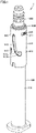
Fig. 1 is a perspective view of a syringe with safety mechanism in one embodiment of the present invention. -
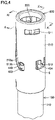
Fig. 2 is a perspective view of a state where a cap has been removed from the syringe with safety mechanism shown inFig. 1 . -
Fig. 3 is a perspective view of a state where a needle cover is located at a protection position. -
Fig. 4 is a perspective view in a state where a guide protrusion abuts on an abutment surface. -
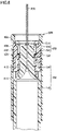
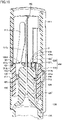
Fig. 5 is a cross-sectional view of the syringe with safety mechanism shown inFig. 1 . -
Fig. 6 is a cross-sectional view of a state where the cap has been removed as compared withFig. 5 . -
Fig. 7 is a cross-sectional view showing a state of slight displacement toward a needle cover protection position as compared withFig. 6 . -
Fig. 8 is a cross-sectional view of a state where the needle cover is located at the protection position. -
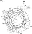
Fig. 9 is a perspective view of a holder. -
Fig. 10 is a cross-sectional view along the line X-X shown inFig. 4 . -
Fig. 11 is a cross-sectional view along the line XI-XI shown inFig. 4 . -
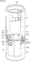
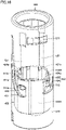
Fig. 12 is a perspective view of the holder and the needle cover in a state where the needle cover is located at a use position. -
Fig. 13 is a cross-sectional view along the line XIII-XIII inFig. 12 . -
Fig. 14 is a perspective view showing a state of slight displacement of the needle cover toward the protection position from the state shown inFig. 12 . -
Fig. 15 is a perspective view of the holder and the needle cover in a state where the needle cover is located at the protection position. -
Fig. 16 is a perspective view showing a state of displacement of the needle cover toward the use position along an axial direction from the state shown inFig. 15 . - An embodiment of this invention will be described with reference to the drawings. The same or corresponding members in the drawings referred to below have the same reference characters allotted.
- As shown in
Figs. 1 to 9 , a syringe withsafety mechanism 1 includes asyringe 100, aneedle 200, aneedle cap 300, aholder 400, and aneedle cover 500. When this syringe withsafety mechanism 1 is used,needle cap 300 is removed therefrom, and after use,needle cover 500 is moved from a use position (a position shown inFig. 2 ) to a protection position (a position shown inFig. 3 ), so that inadvertent prick or the like can be suppressed. - Syringe 100 includes a cylindrically formed barrel
main body 110 and aneedle holding portion 120 connected to a tip end portion (an upper end portion inFig. 5 ) of barrelmain body 110. Each figure does not show a plunger and a gasket. -
Needle holding portion 120 is smaller in outer geometry than barrelmain body 110.Needle holding portion 120 holdsneedle 200. As shown inFigs. 5 to 8 , atip end portion 122 of the needle holding portion is in a shape extending in a radially outward direction of barrelmain body 110. -
Needle cap 300 is attached tosyringe 100 to coverneedle 200. Specifically,needle cap 300 has an opening end portion 310 (seeFig. 5 ) fitted totip end portion 122 ofneedle holding portion 120. Needlecap 300 is removable fromsyringe 100. -
Holder 400 is fixed toneedle holding portion 120 ofsyringe 100.Holder 400 is not displaceable relatively with respect to barrelmain body 110 in an axial direction of barrelmain body 110 but relatively rotatable with respect to barrelmain body 110 around a central axis of barrelmain body 110.Holder 400 includes a surroundingcylinder 410, aneck portion 420, alocking cylinder 430, and aguide protrusion 440. - Surrounding
cylinder 410 surroundsneedle holding portion 120. Surroundingcylinder 410 is cylindrically formed. Surroundingcylinder 410 is rotatable relatively with respect toneedle holding portion 120 around the central axis of barrelmain body 110. As shown inFig. 9 , a notch that extends in the axial direction of surroundingcylinder 410 is provided in surroundingcylinder 410. -
Neck portion 420 is in a shape protruding in the radially inward direction of surroundingcylinder 410 from the tip end portion (the upper end portion inFig. 5 ) of surroundingcylinder 410.Neck portion 420 is engaged withtip end portion 122 ofneedle holding portion 120. Detachment ofholder 400 from barrelmain body 110 is thus prevented. - Locking
cylinder 430 is a portion that locksneedle cover 500.Locking cylinder 430 is formed on an outer side of surroundingcylinder 410 in the radial direction of surroundingcylinder 410.Locking cylinder 430 is in a shape that extends toward one side and the other side in the axial direction of surroundingcylinder 410 from an outer peripheral portion ofneck portion 420. As shown inFig. 5 ,locking cylinder 430 surroundsopening end portion 310 ofneedle cap 300.Opening end portion 310 is pressed into lockingcylinder 430. Details of lockingcylinder 430 will be described later. -
Guide protrusion 440 is in a shape protruding in the radially outward direction of surroundingcylinder 410 from an outer circumferential surface of lockingcylinder 430.Guide protrusion 440 is formed like a disc or a column. In the present embodiment,holder 400 includes a pair ofguide protrusions 440 provided at positions between which the center of surroundingcylinder 410 lies. -
Needle cover 500 is displaceable relatively with respect tosyringe 100 along the axial direction ofsyringe 100 from the use position (the position shown inFig. 2 ) whereneedle 200 is exposed toward the protection position (the position shown inFig. 3 ) whereneedle 200 is surrounded. More specifically,needle cover 500 is displaceable relatively with respect to barrelmain body 110 from the use position toward the protection position whileneedle cap 300 is not attached tosyringe 100. On the other hand, displacement ofneedle cover 500 along the axial direction of barrelmain body 110 from the protection position toward the use position is restricted.Needle cover 500 includes a covermain body 510 and anexpansion portion 520. - Cover
main body 510 is cylindrically formed. Covermain body 510 has an inner diameter as large as or slightly larger than an outer diameter of barrelmain body 110. Covermain body 510 surrounds lockingcylinder 430. Covermain body 510 includes a useposition engagement portion 511, a protectionposition engagement portion 512, and aguide groove 513. - Use
position engagement portion 511 is a portion where covermain body 510 is engaged withlocking cylinder 430 at the use position. In the present embodiment, useposition engagement portion 511 is provided as a through hole that passes through covermain body 510 in the radial direction thereof. Useposition engagement portion 511 is provided in the vicinity of the tip end portion of covermain body 510 in an orientation (which is denoted as a "direction of protection" below) in which covermain body 510 moves from the use position toward the protection position. - Protection
position engagement portion 512 is a portion where covermain body 510 is engaged withlocking cylinder 430 at the protection position. In the present embodiment, protectionposition engagement portion 512 is provided as a through hole that passes through covermain body 510 in the radial direction thereof. Protectionposition engagement portion 512 is provided at a portion of covermain body 510 distant from useposition engagement portion 511 in an orientation opposite to the direction of protection. -
Guide groove 513 guides guideprotrusion 440 when covermain body 510 is displaced from the use position toward the protection position. In other words, guideprotrusion 440 is in a shape protruding towardneedle cover 500, and moves withinguide groove 513 when covermain body 510 is displaced from the use position to the protection position.Guide groove 513 is provided as a through hole that passes through covermain body 510 in the radial direction thereof.Guide groove 513 includes aguide surface 513a and anabutment surface 513b. -
Guide surface 513a is in a shape that causes covermain body 510 to rotate around the central axis of barrelmain body 110 when covermain body 510 is displaced from the use position to the protection position. In the present embodiment,guide surface 513a is in a shape that causes covermain body 510 to rotate by forty-five degrees around the central axis of barrelmain body 110 when covermain body 510 is displaced from the use position to the protection position. - As shown in
Figs. 4 and10 ,abutment surface 513b abuts onguide protrusion 440 when covermain body 510 is displaced from the protection position toward the use position along the axial direction of barrelmain body 110. Therefore, displacement of covermain body 510 from the protection position toward the use position along the axial direction of barrelmain body 110 is restricted. In other words, guideprotrusion 440 constitutes the protruding portion that protrudes towardneedle cover 500 andabutment surface 513b constitutes the restriction portion that restricts relative displacement of covermain body 510 with respect to barrelmain body 110 from the protection position toward the use position along the axial direction of barrelmain body 110. Whileguide protrusion 440 abuts onabutment surface 513b (a state shown inFigs. 4 ,10 , and11 ),needle 200 is surrounded byneedle cover 500. -
Expansion portion 520 is in a shape that expands in the radially inward direction of covermain body 510 from an inner circumferential surface of covermain body 510.Expansion portion 520 includes a firstlongitudinal rib 521 and a secondlongitudinal rib 522. - As shown in
Fig. 10 , firstlongitudinal rib 521 is provided at a position distant fromabutment surface 513b in the direction of protection (upward inFig. 10 ). Firstlongitudinal rib 521 is in a shape extending along the axial direction of covermain body 510. As shown inFigs. 10 and13 ,expansion portion 520 includes a pair of firstlongitudinal ribs 521 provided at positions between which the central axis of covermain body 510 lies. - As shown in
Fig. 11 , secondlongitudinal rib 522 is provided at a position distant from protectionposition engagement portion 512 in the direction of protection (upward inFig. 11 ). Secondlongitudinal rib 522 is in a shape extending along the axial direction of covermain body 510. Secondlongitudinal rib 522 is provided at a position turned by ninety degrees from firstlongitudinal rib 521 in the circumferential direction of covermain body 510. As shown inFigs. 11 and13 ,expansion portion 520 includes a pair of secondlongitudinal ribs 522 provided at positions between which the central axis of covermain body 510 lies. - Locking
cylinder 430 will now be described. As shown inFig. 9 , lockingcylinder 430 includes afirst wall portion 432, asecond wall portion 431, and a lockingportion 433. -
First wall portion 432 is formed at a position opposed toexpansion portion 520 at the use position in the radial direction ofneedle cover 500. In the present embodiment, lockingcylinder 430 includes fourfirst wall portions 432 provided at ninety-degree intervals along the circumferential direction of surroundingcylinder 410.First wall portion 432 opposed to firstlongitudinal rib 521 ofneedle cover 500 at the use position in the radial direction ofneedle cover 500 may be denoted as a "first wall portion 432A" andfirst wall portion 432 opposed to secondlongitudinal rib 522 ofneedle cover 500 at the use position in the radial direction ofneedle cover 500 may be denoted as a "first wall portion 432B" below. - Each
first wall portion 432 allows displacement ofneedle cover 500 from the use position toward the protection position while it rotates around the central axis of barrelmain body 110. An outer surface of eachfirst wall portion 432 is formed as being flat. As shown inFig. 13 , a gap is provided between firstlongitudinal rib 521 ofneedle cover 500 at the use position andfirst wall portion 432A opposed thereto. A gap is provided between secondlongitudinal rib 522 ofneedle cover 500 at the use position andfirst wall portion 432B opposed thereto. Therefore, as shown inFigs. 12 to 15 , displacement ofneedle cover 500 from the use position toward the protection position while it rotates around the central axis of barrelmain body 110 is allowed.Figs. 12 ,14 , and15 show only firstlongitudinal rib 521 ofexpansion portion 520.Fig. 14 does not show a lockingprotrusion 435. -
Second wall portion 431 is provided between adjacentfirst wall portions 432. In other words, lockingcylinder 430 includes a pair ofsecond wall portions 431 between which the center of surroundingcylinder 410 lies. More specifically, eachsecond wall portion 431 is provided at a position adjacent tofirst wall portion 432A (first wall portion 432 opposed in the radial direction to firstlongitudinal rib 521 at the use position) in a direction the same as a direction of rotation ofneedle cover 500 around the central axis of barrelmain body 110 whenneedle cover 500 is displaced from the use position to the protection position. Eachsecond wall portion 431 is larger in thickness thanfirst wall portion 432. - Each
second wall portion 431 includes a receivingportion 431a formed at a tip end in the direction of protection. Receivingportion 431a is opposed in the axial direction to firstlongitudinal rib 521 ofneedle cover 500 at the protection position and abuts on firstlongitudinal rib 521 whenneedle cover 500 is displaced from the protection position toward the use position along the axial direction. In other words, firstlongitudinal rib 521 constitutes the protruding portion that protrudes towardholder 400 and receivingportion 431a constitutes the restriction portion that restricts relative displacement ofneedle cover 500 with respect to barrelmain body 110 from the protection position toward the use position along the axial direction of barrelmain body 110. - Locking
portion 433locks needle cover 500 from the radially inner side ofneedle cover 500. Lockingportion 433 holdsneedle cover 500 at the use position. Specifically, lockingportion 433 is engaged with useposition engagement portion 511 ofneedle cover 500 at the use position. Lockingportion 433 holdsneedle cover 500 at the protection position. Specifically, lockingportion 433 is engaged with protectionposition engagement portion 512 ofneedle cover 500 at the protection position. - Locking
portion 433 is provided between adjacentfirst wall portions 432. In other words, lockingcylinder 430 includes a pair of lockingportions 433 between which the center of surroundingcylinder 410 lies. More specifically, each lockingportion 433 is provided at a position adjacent tofirst wall portion 432B (first wall portion 432 opposed in the radial direction to secondlongitudinal rib 522 at the use position) in a direction the same as the direction of rotation ofneedle cover 500 around the central axis of barrelmain body 110 whenneedle cover 500 is displaced from the use position to the protection position. - A pair of slits S is provided on opposing sides of each locking
portion 433 of lockingcylinder 430. Each lockingportion 433 can thus be bent in the radially inward direction of surroundingcylinder 410. Lockingportion 433 includes aflexible piece 434 and lockingprotrusion 435. -
Flexible piece 434 lies between the pair of slits S and formed like a plate. - Locking
protrusion 435 is in a shape protruding radially outward from an outer surface offlexible piece 434. Lockingprotrusion 435 is engaged with useposition engagement portion 511 and protectionposition engagement portion 512 from the radially inner side ofneedle cover 500. Lockingprotrusion 435 is provided on an outer surface of a tip end portion offlexible piece 434 in the direction of protection. -
Flexible piece 434 is elastically deformable such that lockingprotrusion 435 is displaced between an engagement position and a detachment position. The engagement position refers to a position (a position shown inFig. 6 ) where lockingprotrusion 435 is engaged with useposition engagement portion 511 whileneedle cover 500 is located at the use position. The detachment position refers to a position (a position shown inFig. 7 ) where lockingprotrusion 435 is detached radially inward from useposition engagement portion 511 whenneedle cover 500 is displaced from the use position to the protection position. - As shown in
Figs. 9 to 11 ,flexible piece 434 includes a receivingportion 434a formed at a tip end in the direction of protection. Receivingportion 434a is opposed in the axial direction to secondlongitudinal rib 522 ofneedle cover 500 at the protection position and abuts on secondlongitudinal rib 522 whenneedle cover 500 is displaced from the protection position toward the use position along the axial direction. In other words, secondlongitudinal rib 522 constitutes the protruding portion that protrudes towardholder 400 and receivingportion 434a constitutes the restriction portion that restricts relative displacement ofneedle cover 500 with respect to barrelmain body 110 along the axial direction of barrelmain body 110 from the protection position toward the use position. - As shown in
Fig. 5 , whileneedle cap 300 is attached tosyringe 100, openingend portion 310 ofneedle cap 300 is pressed in betweentip end portion 122 ofneedle holding portion 120 andflexible piece 434. In other words, openingend portion 310 constitutes a support portion that supports lockingportion 433 from the radially inner side to restrict radially inward bending of lockingportion 433. - A procedure of use of syringe with
safety mechanism 1 will now be described. Initially, before this syringe withsafety mechanism 1 is used, as shown inFigs. 1 and5 ,needle cap 300 is attached tosyringe 100. In this state, opening end portion (support portion) 310 ofneedle cap 300supports locking portion 433 from the radially inner side. Therefore, radially inward bending of lockingportion 433 is suppressed. Therefore, whileneedle cap 300 is attached tosyringe 100,needle cover 500 is held at the use position. In other words, with this syringe withsafety mechanism 1, displacement ofneedle cover 500 to the protection position before removal ofneedle cap 300 is restricted. - At the time of use of syringe with
safety mechanism 1,needle cap 300 is removed.Needle 200 is thus exposed. - Then, after use,
needle cover 500 is moved from the use position toward the protection position with respect to barrelmain body 110. When this movement is started, there is no support of lockingportion 433 by openingend portion 310 ofneedle cap 300. Therefore, lockingprotrusion 435 is pressed by covermain body 510, andflexible piece 434 is bent radially inward. Therefore, movement ofneedle cover 500 in the direction of protection is allowed.Needle cover 500 moves to the protection position while it rotates around the central axis of barrelmain body 110 alongguide groove 513. Whenneedle cover 500 moves as rotating, firstlongitudinal rib 521 is maintained distant fromfirst wall portion 432A and secondlongitudinal rib 522 is maintained distant fromfirst wall portion 432B. - Then, when
needle cover 500 reaches the protection position,flexible piece 434 returns such that lockingprotrusion 435 is engaged with protectionposition engagement portion 512. Therefore,needle cover 500 is held at the protection position. At this time, as shown inFig. 15 , firstlongitudinal rib 521 is opposed in the axial direction to receivingportion 431a ofsecond wall portion 431. Secondlongitudinal rib 522 is opposed in the axial direction to receivingportion 434a offlexible piece 434. - When external force that causes
needle cover 500 to move from the protection position to the use position along the axial direction of barrelmain body 110 is applied toneedle cover 500, as shown inFigs. 4 ,10 , and16 ,guide protrusion 440 abuts onabutment surface 513b, firstlongitudinal rib 521 abuts on receivingportion 431a ofsecond wall portion 431, and secondlongitudinal rib 522 abuts on receivingportion 434a offlexible piece 434. Therefore, further displacement ofneedle cap 500 in an orientation opposite to the direction of protection along the axial direction of barrelmain body 110 is restricted.Fig. 16 does not show secondlongitudinal rib 522. - Thus, while the protruding portion (guide
protrusion 440, firstlongitudinal rib 521, second longitudinal rib 522) abuts on the restriction portion (abutment surface 513b, receivingportion 431a, receivingportion 434a),needle 200 is surrounded byneedle cover 500. Therefore, occurrence of inadvertent prick or the like after use is suppressed. - In the present embodiment, locking
portion 433 performs both of a function to lockneedle cover 500 at the use position or the protection position and a function to restrict displacement ofneedle cover 500 from the protection position toward the use position along the axial direction by being in coordination with secondlongitudinal rib 522. - It should be understood that the embodiment disclosed herein is illustrative and non-restrictive in every respect. The scope of the present invention is defined by the terms of the claims rather than the description of the embodiment above and is intended to include any modifications within the scope and meaning equivalent to the terms of the claims.
- For example, displacement of
needle cap 500 with respect tosyringe 100 from the protection position toward the use position along the axial direction can be restricted by a restriction mechanism composed of a single protruding portion and a single restriction portion. Therefore, any one or two of a restriction mechanism composed ofguide protrusion 440 andabutment surface 513b, a restriction mechanism composed of firstlongitudinal rib 521 and receivingportion 431a, and a restriction mechanism composed of secondlongitudinal rib 522 and receivingportion 434a may be omitted. - An illustrative embodiment described above is understood by a person skilled in the art as a specific example of aspects below.
- A syringe with safety mechanism according to one aspect of this invention includes a syringe, a needle connected to a tip end portion of the syringe, a holder fixed to the syringe, and a needle cover displaceable relatively with respect to the syringe along an axial direction of the syringe from a use position where the needle is exposed toward a protection position where the needle is surrounded, the holder includes a locking portion that locks the needle cover at the use position from a radially inner side of the needle cover to hold the needle cover at the use position and locks the needle cover at the protection position from the radially inner side to hold the needle cover at the protection position, and at least one member of the holder and the needle cover includes a protruding portion that protrudes toward the other member of the holder and the needle cover and the other member includes a restriction portion that abuts on the protruding portion to restrict relative displacement of the needle cover with respect to the syringe along the axial direction of the syringe from the protection position toward the use position.
- In this syringe with safety mechanism, at least one member of the holder and the needle cover includes the protruding portion and the other member includes the restriction portion. Therefore, the protruding portion abuts on the restriction portion when the needle cover is relatively displaced with respect to the syringe from the protection position toward the use position along the axial direction of the syringe. Therefore, displacement of the needle cover from the protection position to the use position is suppressed.
- In the syringe with safety mechanism, the holder may include a guide protrusion in a shape protruding toward the needle cover, the needle cover may be provided with a guide groove that guides the guide protrusion when the needle cover is displaced from the use position toward the protection position, the guide groove may include a guide surface in a shape that causes the needle cover to rotate around a central axis of the syringe when the needle cover is displaced from the use position to the protection position and an abutment surface that abuts on the guide protrusion when the needle cover is displaced from the protection position toward the use position along the axial direction, and the guide protrusion may constitute the protruding portion and the abutment surface may constitute the restriction portion.
- In this aspect, the guide protrusion achieves both of stable movement of the needle cover from the use position to the protection position and suppression of displacement of the needle cover from the protection position to the use position.
- Alternatively, in the syringe with safety mechanism, the needle cover may include an expansion portion that expands toward the holder, the holder may include a receiving portion that is opposed in the axial direction to the expansion portion of the needle cover at the protection position and abuts on the expansion portion when the needle cover is displaced from the protection position toward the use position along the axial direction, and the expansion portion may constitute the protruding portion and the receiving portion may constitute the restriction portion.
- In this case, preferably, the holder includes a guide protrusion in a shape protruding toward the needle cover, the needle cover is provided with a guide groove that guides the guide protrusion when the needle cover is displaced from the use position toward the protection position, the guide groove includes a guide surface in a shape that causes the needle cover to rotate around a central axis of the syringe when the needle cover is displaced from the use position to the protection position, the holder includes a first wall portion formed at a position where the first wall portion is opposed to the expansion portion of the needle cover at the use position in a radial direction of the needle cover, the first wall portion allowing displacement of the needle cover from the use position toward the protection position while the needle cover rotates around the central axis of the syringe and a second wall portion provided at a position adjacent to the first wall portion in a direction identical to a direction of rotation of the needle cover around the central axis of the syringe when the needle cover is displaced from the use position to the protection position, and a tip end portion of the second wall portion in an orientation in which the needle cover moves from the use position toward the protection position constitutes the receiving portion.
- In this aspect, both of smooth movement of the needle cover from the use position to the protection position and suppression of displacement of the needle cover from the protection position to the use position are achieved.
- Further in this case, preferably, the holder further includes another first wall portion different from the first wall portion, the locking portion is provided at a position adjacent to another first wall portion in the direction identical to the direction of rotation of the needle cover around the central axis of the syringe when the needle cover is displaced from the use position to the protection position, the expansion portion includes a first longitudinal rib opposed to the first wall portion in the radial direction of the needle cover when the needle cover is located at the use position and opposed to the second wall portion in the axial direction when the needle cover is located at the protection position and a second longitudinal rib opposed to another first wall portion in the radial direction of the needle cover when the needle cover is located at the use position and opposed to the locking portion in the axial direction when the needle cover is located at the protection position, and a tip end portion of the locking portion in the orientation in which the needle cover moves from the use position toward the protection position constitutes the receiving portion.
- Displacement of the needle cover from the protection position to the use position is thus more reliably suppressed.
- Preferably, the guide groove further includes an abutment surface that abuts on the guide protrusion when the needle cover is displaced from the protection position toward the use position along the axial direction, and the guide protrusion constitutes the protruding portion and the abutment surface constitutes the restriction portion.
- As set forth above, according to the syringe with safety mechanism according to the one aspect of this invention, displacement of the needle cover from the protection position to the use position is suppressed.
- A syringe with safety mechanism according to another aspect of this invention includes a syringe, a needle connected to a tip end portion of the syringe, a needle cap attached to the syringe to cover the needle, the needle cap being removable from the syringe, a holder fixed to the syringe, and a needle cover displaceable relatively with respect to the syringe along an axial direction of the syringe from a use position where the needle is exposed while the needle cap is not attached to the syringe toward a protection position where the needle is surrounded while the needle cap is not attached to the syringe, the holder includes a locking portion that locks the needle cover at the use position from a radially inner side of the needle cover to hold the needle cover at the use position, the locking portion is elastically deformable to be bent radially inward to allow movement of the needle cover from the use position to the protection position, and the needle cap includes a support portion that supports the locking portion from the radially inner side to restrict radially inward bending of the locking portion.
- With this syringe with safety mechanism, while the needle cap is attached to the syringe, the support portion of the needle cap supports the locking portion from the radially inner side. Therefore, radially inward bending of the locking portion is suppressed. Therefore, while the needle cap is attached to the syringe, the needle cover is held at the use position. In other words, with this syringe with safety mechanism, displacement of the needle cover to the protection position before removal of the needle cap is restricted. On the other hand, while the needle cap is not attached to the syringe, the locking portion can be bent radially inward, and hence displacement of the needle cover from the use position to the protection position is allowed.
- Preferably, in the holder, on each of opposing sides of the locking portion in a circumferential direction of the holder, a slit that extends in a direction in parallel to the axial direction of the syringe is provided.
- The locking portion is thus effectively elastically deformed when the needle cover is displaced from the use position to the protection position.
- Preferably, the locking portion includes a flexible piece in a shape extending in the direction in parallel to the axial direction of the syringe and a locking protrusion in a shape protruding radially outward from the flexible piece, the needle cover includes a use position engagement portion engaged with the locking protrusion at the use position, and the flexible piece is elastically deformable such that the locking protrusion is displaced between an engagement position where the locking protrusion is engaged with the use position engagement portion while the needle cover is located at the use position and a detachment position where the locking protrusion is detached radially inward from the use position engagement portion when the needle cover is displaced from the use position to the protection position.
- In this case, preferably, the needle cover further includes a protection position engagement portion engaged with the locking protrusion at the protection position.
- Displacement of the needle cover from the protection position to the use position after use is thus suppressed.
- As set forth above, according to the syringe with safety mechanism according to another aspect of this invention, sliding of the needle cover to the protection position before the needle cap is removed is restricted.
- 1 syringe with safety mechanism; 100 syringe; 110 barrel main body; 120 needle holding portion; 122 tip end portion; 200 needle; 300 needle cap; 310 opening end portion (support portion); 400 holder; 410 surrounding cylinder; 420 neck portion; 430 locking cylinder; 431 second wall portion; 431a receiving portion (restriction portion); 432 first wall portion; 432A first wall portion; 432B first wall portion; 433 locking portion; 434 flexible piece; 434a receiving portion (restriction portion); 435 locking protrusion; 440 guide protrusion (protruding portion); 500 needle cover; 510 cover main body; 511 use position engagement portion; 512 protection position engagement portion; 513 guide groove; 513a guide surface; 513b abutment surface (restriction portion); 520 expansion portion (protruding portion); 521 first longitudinal rib (protruding portion); 522 second longitudinal rib (protruding portion)
Claims (10)
- A syringe with safety mechanism comprising:a syringe;a needle connected to a tip end portion of the syringe;a holder fixed to the syringe; anda needle cover displaceable relatively with respect to the syringe along an axial direction of the syringe from a use position where the needle is exposed toward a protection position where the needle is surrounded, whereinthe holder includes a locking portion that locks the needle cover at the use position from a radially inner side of the needle cover to hold the needle cover at the use position and locks the needle cover at the protection position from the radially inner side to hold the needle cover at the protection position, andat least one member of the holder and the needle cover includes a protruding portion that protrudes toward the other member of the holder and the needle cover and the other member includes a restriction portion that abuts on the protruding portion to restrict relative displacement of the needle cover with respect to the syringe along the axial direction of the syringe from the protection position toward the use position.
- The syringe with safety mechanism according to claim 1, whereinthe holder includes a guide protrusion in a shape protruding toward the needle cover,the needle cover is provided with a guide groove that guides the guide protrusion when the needle cover is displaced from the use position toward the protection position,the guide groove includesa guide surface in a shape that causes the needle cover to rotate around a central axis of the syringe when the needle cover is displaced from the use position to the protection position, andan abutment surface that abuts on the guide protrusion when the needle cover is displaced from the protection position toward the use position along the axial direction, andthe guide protrusion constitutes the protruding portion and the abutment surface constitutes the restriction portion.
- The syringe with safety mechanism according to claim 1, whereinthe needle cover includes an expansion portion that expands toward the holder,the holder includes a receiving portion that is opposed in the axial direction to the expansion portion of the needle cover at the protection position and abuts on the expansion portion when the needle cover is displaced from the protection position toward the use position along the axial direction, andthe expansion portion constitutes the protruding portion and the receiving portion constitutes the restriction portion.
- The syringe with safety mechanism according to claim 3, whereinthe holder includes a guide protrusion in a shape protruding toward the needle cover,the needle cover is provided with a guide groove that guides the guide protrusion when the needle cover is displaced from the use position toward the protection position,the guide groove includes a guide surface in a shape that causes the needle cover to rotate around a central axis of the syringe when the needle cover is displaced from the use position to the protection position,the holder includesa first wall portion formed at a position where the first wall portion is opposed to the expansion portion of the needle cover at the use position in a radial direction of the needle cover, the first wall portion allowing displacement of the needle cover from the use position toward the protection position while the needle cover rotates around the central axis of the syringe, anda second wall portion provided at a position adjacent to the first wall portion in a direction identical to a direction of rotation of the needle cover around the central axis of the syringe when the needle cover is displaced from the use position to the protection position, anda tip end portion of the second wall portion in an orientation in which the needle cover moves from the use position toward the protection position constitutes the receiving portion.
- The syringe with safety mechanism according to claim 4, whereinthe holder further includes another first wall portion different from the first wall portion,the locking portion is provided at a position adjacent to the another first wall portion in a direction identical to the direction of rotation of the needle cover around the central axis of the syringe when the needle cover is displaced from the use position to the protection position,the expansion portion includesa first longitudinal rib opposed to the first wall portion in the radial direction of the needle cover when the needle cover is located at the use position and opposed to the second wall portion in the axial direction when the needle cover is located at the protection position, anda second longitudinal rib opposed to the another first wall portion in the radial direction of the needle cover when the needle cover is located at the use position and opposed to the locking portion in the axial direction when the needle cover is located at the protection position, anda tip end portion of the locking portion in the orientation in which the needle cover moves from the use position toward the protection position constitutes the receiving portion.
- The syringe with safety mechanism according to claim 4 or 5, whereinthe guide groove further includes an abutment surface that abuts on the guide protrusion when the needle cover is displaced from the protection position toward the use position along the axial direction, andthe guide protrusion constitutes the protruding portion and the abutment surface constitutes the restriction portion.
- The syringe with safety mechanism according to claim 1, further comprising a needle cap attached to the syringe to cover the needle, the needle cap being removable from the syringe, whereinthe needle cover is displaceable relatively with respect to the syringe from the use position toward the protection position while the needle cap is not attached to the syringe,the locking portion is elastically deformable to be bent radially inward to allow movement of the needle cover from the use position to the protection position, andthe needle cap includes a support portion that supports the locking portion from the radially inner side to restrict radially inward bending of the locking portion.
- The syringe with safety mechanism according to claim 7, wherein
in the holder, on each of opposing sides of the locking portion in a circumferential direction of the holder, a slit that extends in a direction in parallel to the axial direction of the syringe is provided. - The syringe with safety mechanism according to claim 8, whereinthe locking portion includesa flexible piece in a shape extending in the direction in parallel to the axial direction of the syringe, anda locking protrusion in a shape protruding radially outward from the flexible piece,the needle cover includes a use position engagement portion engaged with the locking protrusion at the use position, andthe flexible piece is elastically deformable such that the locking protrusion is displaced between an engagement position where the locking protrusion is engaged with the use position engagement portion while the needle cover is located at the use position and a detachment position where the locking protrusion is detached radially inward from the use position engagement portion when the needle cover is displaced from the use position to the protection position.
- The syringe with safety mechanism according to claim 9, wherein
the needle cover further includes a protection position engagement portion engaged with the locking protrusion at the protection position.
Applications Claiming Priority (3)
| Application Number | Priority Date | Filing Date | Title |
|---|---|---|---|
| JP2019222815A JP7380163B2 (en) | 2019-12-10 | 2019-12-10 | Syringe with safety mechanism |
| JP2019222817A JP7443738B2 (en) | 2019-12-10 | 2019-12-10 | Syringe with safety mechanism |
| PCT/JP2020/045771 WO2021117751A1 (en) | 2019-12-10 | 2020-12-09 | Syringe with safety mechanism |
Publications (2)
| Publication Number | Publication Date |
|---|---|
| EP4070836A1 true EP4070836A1 (en) | 2022-10-12 |
| EP4070836A4 EP4070836A4 (en) | 2023-12-13 |
Family
ID=76329878
Family Applications (1)
| Application Number | Title | Priority Date | Filing Date |
|---|---|---|---|
| EP20899324.6A Pending EP4070836A4 (en) | 2019-12-10 | 2020-12-09 | SYRINGE WITH SAFETY MECHANISM |
Country Status (6)
| Country | Link |
|---|---|
| US (1) | US12485230B2 (en) |
| EP (1) | EP4070836A4 (en) |
| KR (1) | KR102719156B1 (en) |
| CN (1) | CN115038482B (en) |
| MX (1) | MX2022006961A (en) |
| WO (1) | WO2021117751A1 (en) |
Families Citing this family (1)
| Publication number | Priority date | Publication date | Assignee | Title |
|---|---|---|---|---|
| EP4319848A4 (en) | 2021-04-08 | 2025-02-26 | Love Lifesciences LLC | SAFETY DEVICES AND PRE-FILLED SYRINGE INJECTORS, SYSTEMS AND METHODS OF USE |
Family Cites Families (23)
| Publication number | Priority date | Publication date | Assignee | Title |
|---|---|---|---|---|
| FR2837107B1 (en) | 2002-03-18 | 2005-02-25 | Sedat | NEEDLE PROTECTION DEVICE FOR SYRINGE, AND INJECTION DEVICE COMPRISING SYRINGE AND PROTECTIVE DEVICE |
| FR2874505B1 (en) | 2004-08-27 | 2007-06-08 | Sedat Sa | INJECTION DEVICE COMPRISING A SYRINGE |
| AU2005326534A1 (en) | 2005-02-03 | 2006-08-10 | Douglas Arthur Emmott | A safety needle |
| US8597255B2 (en) | 2005-02-03 | 2013-12-03 | Salvus Technology Limited | Safety needle |
| DE102006041809B4 (en) | 2006-09-06 | 2012-11-15 | Tecpharma Licensing Ag | Needle protection device with blocking device |
| GB0823066D0 (en) | 2008-12-18 | 2009-01-28 | Medical House Plc The | Safety syringe for autoinjector |
| JP5433075B2 (en) * | 2009-04-27 | 2014-03-05 | エス・ホー・エル・グループ・アクチボラゲット | Safety pen needle device |
| US8663174B2 (en) | 2009-11-13 | 2014-03-04 | Becton, Dickinson And Company | Hub assembly having a hidden needle for a drug delivery pen |
| DK3721925T3 (en) * | 2010-07-02 | 2023-07-24 | Sanofi Aventis Deutschland | SAFETY DEVICE FOR A FILLED SYRINGE, INJECTION DEVICE AND INJECTION KIT |
| EP2468333A1 (en) | 2010-12-21 | 2012-06-27 | Sanofi-Aventis Deutschland GmbH | Auto-injector |
| CN103429286B (en) * | 2011-01-04 | 2016-03-16 | 赛诺菲-安万特德国有限公司 | Safety devices and injection devices for prefilled syringes |
| EP2714156B1 (en) * | 2011-06-02 | 2018-07-11 | West Pharmaceutical Services, Inc. | Needle-protection device for a syringe |
| BR112014005036B1 (en) * | 2011-08-31 | 2020-12-29 | Shl Medical Ag | injection device |
| US10342930B1 (en) * | 2012-01-09 | 2019-07-09 | Verena Solutions LLC | Protective cover for a syringe needle |
| US10004854B2 (en) * | 2012-03-07 | 2018-06-26 | West Pharmaceutical Services, Inc. | Low radial profile needle safety device |
| CA2873681C (en) * | 2013-12-10 | 2022-05-24 | Becton, Dickinson And Company | Passive safety pen needle assembly |
| EP3117856A4 (en) | 2014-03-11 | 2017-10-04 | Nipro Corporation | Needle assembly |
| JPWO2016158627A1 (en) | 2015-03-30 | 2018-01-25 | テルモ株式会社 | Puncture needle protecting assembly, syringe assembly and manufacturing method thereof |
| CN108697842A (en) * | 2016-02-25 | 2018-10-23 | 诺和诺德股份有限公司 | Medical injection device with axially movable shield |
| US12478772B2 (en) | 2016-08-04 | 2025-11-25 | Nipro Corporation | Valved needle assembly and indwelling needle assembly |
| JP6886146B2 (en) | 2017-06-27 | 2021-06-16 | 大成化工株式会社 | Syringe |
| WO2019061420A1 (en) * | 2017-09-30 | 2019-04-04 | 群康生技股份有限公司 | Safety needle and safety needle device |
| KR200491264Y1 (en) | 2017-10-26 | 2020-03-11 | (주)신아메드 | safety syringe |
-
2020
- 2020-12-09 US US17/783,909 patent/US12485230B2/en active Active
- 2020-12-09 WO PCT/JP2020/045771 patent/WO2021117751A1/en not_active Ceased
- 2020-12-09 EP EP20899324.6A patent/EP4070836A4/en active Pending
- 2020-12-09 MX MX2022006961A patent/MX2022006961A/en unknown
- 2020-12-09 KR KR1020227022868A patent/KR102719156B1/en active Active
- 2020-12-09 CN CN202080095585.3A patent/CN115038482B/en active Active
Also Published As
| Publication number | Publication date |
|---|---|
| US12485230B2 (en) | 2025-12-02 |
| KR20220110545A (en) | 2022-08-08 |
| CA3161398A1 (en) | 2021-06-17 |
| CN115038482A (en) | 2022-09-09 |
| WO2021117751A1 (en) | 2021-06-17 |
| US20230001102A1 (en) | 2023-01-05 |
| EP4070836A4 (en) | 2023-12-13 |
| KR102719156B1 (en) | 2024-10-17 |
| CN115038482B (en) | 2024-04-30 |
| MX2022006961A (en) | 2022-08-08 |
Similar Documents
| Publication | Publication Date | Title |
|---|---|---|
| EP1690562A1 (en) | Syringe needle | |
| EP3226944B1 (en) | Needle shield puller cap assembly | |
| CN104284782B (en) | Writing instrument with removable case | |
| EP2455058A1 (en) | Connection device | |
| CN107635609B (en) | Safety device for syringe | |
| US11331454B2 (en) | Needle tip protector for indwelling needle and indwelling needle assembly | |
| US20160220766A1 (en) | Safety needle assembly | |
| AU2016213009B2 (en) | Protection device and medical equipment assembled body | |
| US12485230B2 (en) | Syringe with safety mechanism | |
| CN109475466B (en) | Medicament container holder for a medicament delivery device and method of assembling a medicament delivery device | |
| US11524123B2 (en) | Safety assembly and medical device with safety assembly | |
| WO2014175237A1 (en) | Syringe | |
| KR20090102643A (en) | Rod article feeding-out mechanism | |
| JP7708260B2 (en) | Puncture needle with protector | |
| JP7443738B2 (en) | Syringe with safety mechanism | |
| JP4368583B2 (en) | Devices for medical applications with improved safety, in particular syringes | |
| JP7380163B2 (en) | Syringe with safety mechanism | |
| JPH021289A (en) | Injection device equipped with protector | |
| JP6886146B2 (en) | Syringe | |
| EP3915615B1 (en) | A safety needle device | |
| JP6433369B2 (en) | Syringe | |
| JP7491871B2 (en) | Clip and clip attachment structure | |
| CN110448767A (en) | A kind of fit structure and a kind of injection needle of needle stand and sheath | |
| JP2023118532A (en) | indwelling needle | |
| JP2004524907A (en) | Syringe or similar device |
Legal Events
| Date | Code | Title | Description |
|---|---|---|---|
| STAA | Information on the status of an ep patent application or granted ep patent |
Free format text: STATUS: THE INTERNATIONAL PUBLICATION HAS BEEN MADE |
|
| PUAI | Public reference made under article 153(3) epc to a published international application that has entered the european phase |
Free format text: ORIGINAL CODE: 0009012 |
|
| STAA | Information on the status of an ep patent application or granted ep patent |
Free format text: STATUS: REQUEST FOR EXAMINATION WAS MADE |
|
| 17P | Request for examination filed |
Effective date: 20220707 |
|
| AK | Designated contracting states |
Kind code of ref document: A1 Designated state(s): AL AT BE BG CH CY CZ DE DK EE ES FI FR GB GR HR HU IE IS IT LI LT LU LV MC MK MT NL NO PL PT RO RS SE SI SK SM TR |
|
| DAV | Request for validation of the european patent (deleted) | ||
| DAX | Request for extension of the european patent (deleted) | ||
| A4 | Supplementary search report drawn up and despatched |
Effective date: 20231109 |
|
| RIC1 | Information provided on ipc code assigned before grant |
Ipc: A61M 5/32 20060101AFI20231103BHEP |
|
| STAA | Information on the status of an ep patent application or granted ep patent |
Free format text: STATUS: EXAMINATION IS IN PROGRESS |
|
| 17Q | First examination report despatched |
Effective date: 20250728 |