EP4070764A1 - Stent graft - Google Patents
Stent graft Download PDFInfo
- Publication number
- EP4070764A1 EP4070764A1 EP20896721.6A EP20896721A EP4070764A1 EP 4070764 A1 EP4070764 A1 EP 4070764A1 EP 20896721 A EP20896721 A EP 20896721A EP 4070764 A1 EP4070764 A1 EP 4070764A1
- Authority
- EP
- European Patent Office
- Prior art keywords
- stent
- graft
- opening
- proximal
- cover membrane
- Prior art date
- Legal status (The legal status is an assumption and is not a legal conclusion. Google has not performed a legal analysis and makes no representation as to the accuracy of the status listed.)
- Granted
Links
Images





Classifications
-
- A—HUMAN NECESSITIES
- A61—MEDICAL OR VETERINARY SCIENCE; HYGIENE
- A61F—FILTERS IMPLANTABLE INTO BLOOD VESSELS; PROSTHESES; DEVICES PROVIDING PATENCY TO, OR PREVENTING COLLAPSING OF, TUBULAR STRUCTURES OF THE BODY, e.g. STENTS; ORTHOPAEDIC, NURSING OR CONTRACEPTIVE DEVICES; FOMENTATION; TREATMENT OR PROTECTION OF EYES OR EARS; BANDAGES, DRESSINGS OR ABSORBENT PADS; FIRST-AID KITS
- A61F2/00—Filters implantable into blood vessels; Prostheses, i.e. artificial substitutes or replacements for parts of the body; Appliances for connecting them with the body; Devices providing patency to, or preventing collapsing of, tubular structures of the body, e.g. stents
- A61F2/02—Prostheses implantable into the body
- A61F2/04—Hollow or tubular parts of organs, e.g. bladders, tracheae, bronchi or bile ducts
- A61F2/06—Blood vessels
- A61F2/07—Stent-grafts
-
- A—HUMAN NECESSITIES
- A61—MEDICAL OR VETERINARY SCIENCE; HYGIENE
- A61F—FILTERS IMPLANTABLE INTO BLOOD VESSELS; PROSTHESES; DEVICES PROVIDING PATENCY TO, OR PREVENTING COLLAPSING OF, TUBULAR STRUCTURES OF THE BODY, e.g. STENTS; ORTHOPAEDIC, NURSING OR CONTRACEPTIVE DEVICES; FOMENTATION; TREATMENT OR PROTECTION OF EYES OR EARS; BANDAGES, DRESSINGS OR ABSORBENT PADS; FIRST-AID KITS
- A61F2/00—Filters implantable into blood vessels; Prostheses, i.e. artificial substitutes or replacements for parts of the body; Appliances for connecting them with the body; Devices providing patency to, or preventing collapsing of, tubular structures of the body, e.g. stents
- A61F2/82—Devices providing patency to, or preventing collapsing of, tubular structures of the body, e.g. stents
- A61F2/848—Devices providing patency to, or preventing collapsing of, tubular structures of the body, e.g. stents having means for fixation to the vessel wall, e.g. barbs
-
- A—HUMAN NECESSITIES
- A61—MEDICAL OR VETERINARY SCIENCE; HYGIENE
- A61F—FILTERS IMPLANTABLE INTO BLOOD VESSELS; PROSTHESES; DEVICES PROVIDING PATENCY TO, OR PREVENTING COLLAPSING OF, TUBULAR STRUCTURES OF THE BODY, e.g. STENTS; ORTHOPAEDIC, NURSING OR CONTRACEPTIVE DEVICES; FOMENTATION; TREATMENT OR PROTECTION OF EYES OR EARS; BANDAGES, DRESSINGS OR ABSORBENT PADS; FIRST-AID KITS
- A61F2/00—Filters implantable into blood vessels; Prostheses, i.e. artificial substitutes or replacements for parts of the body; Appliances for connecting them with the body; Devices providing patency to, or preventing collapsing of, tubular structures of the body, e.g. stents
- A61F2/82—Devices providing patency to, or preventing collapsing of, tubular structures of the body, e.g. stents
- A61F2/86—Stents in a form characterised by the wire-like elements; Stents in the form characterised by a net-like or mesh-like structure
- A61F2/90—Stents in a form characterised by the wire-like elements; Stents in the form characterised by a net-like or mesh-like structure characterised by a net-like or mesh-like structure
- A61F2/91—Stents in a form characterised by the wire-like elements; Stents in the form characterised by a net-like or mesh-like structure characterised by a net-like or mesh-like structure made from perforated sheets or tubes, e.g. perforated by laser cuts or etched holes
- A61F2/915—Stents in a form characterised by the wire-like elements; Stents in the form characterised by a net-like or mesh-like structure characterised by a net-like or mesh-like structure made from perforated sheets or tubes, e.g. perforated by laser cuts or etched holes with bands having a meander structure, adjacent bands being connected to each other
-
- A—HUMAN NECESSITIES
- A61—MEDICAL OR VETERINARY SCIENCE; HYGIENE
- A61F—FILTERS IMPLANTABLE INTO BLOOD VESSELS; PROSTHESES; DEVICES PROVIDING PATENCY TO, OR PREVENTING COLLAPSING OF, TUBULAR STRUCTURES OF THE BODY, e.g. STENTS; ORTHOPAEDIC, NURSING OR CONTRACEPTIVE DEVICES; FOMENTATION; TREATMENT OR PROTECTION OF EYES OR EARS; BANDAGES, DRESSINGS OR ABSORBENT PADS; FIRST-AID KITS
- A61F2/00—Filters implantable into blood vessels; Prostheses, i.e. artificial substitutes or replacements for parts of the body; Appliances for connecting them with the body; Devices providing patency to, or preventing collapsing of, tubular structures of the body, e.g. stents
- A61F2/02—Prostheses implantable into the body
- A61F2/04—Hollow or tubular parts of organs, e.g. bladders, tracheae, bronchi or bile ducts
- A61F2/06—Blood vessels
- A61F2/07—Stent-grafts
- A61F2002/072—Encapsulated stents, e.g. wire or whole stent embedded in lining
-
- A—HUMAN NECESSITIES
- A61—MEDICAL OR VETERINARY SCIENCE; HYGIENE
- A61F—FILTERS IMPLANTABLE INTO BLOOD VESSELS; PROSTHESES; DEVICES PROVIDING PATENCY TO, OR PREVENTING COLLAPSING OF, TUBULAR STRUCTURES OF THE BODY, e.g. STENTS; ORTHOPAEDIC, NURSING OR CONTRACEPTIVE DEVICES; FOMENTATION; TREATMENT OR PROTECTION OF EYES OR EARS; BANDAGES, DRESSINGS OR ABSORBENT PADS; FIRST-AID KITS
- A61F2/00—Filters implantable into blood vessels; Prostheses, i.e. artificial substitutes or replacements for parts of the body; Appliances for connecting them with the body; Devices providing patency to, or preventing collapsing of, tubular structures of the body, e.g. stents
- A61F2/02—Prostheses implantable into the body
- A61F2/04—Hollow or tubular parts of organs, e.g. bladders, tracheae, bronchi or bile ducts
- A61F2/06—Blood vessels
- A61F2/07—Stent-grafts
- A61F2002/075—Stent-grafts the stent being loosely attached to the graft material, e.g. by stitching
-
- A—HUMAN NECESSITIES
- A61—MEDICAL OR VETERINARY SCIENCE; HYGIENE
- A61F—FILTERS IMPLANTABLE INTO BLOOD VESSELS; PROSTHESES; DEVICES PROVIDING PATENCY TO, OR PREVENTING COLLAPSING OF, TUBULAR STRUCTURES OF THE BODY, e.g. STENTS; ORTHOPAEDIC, NURSING OR CONTRACEPTIVE DEVICES; FOMENTATION; TREATMENT OR PROTECTION OF EYES OR EARS; BANDAGES, DRESSINGS OR ABSORBENT PADS; FIRST-AID KITS
- A61F2/00—Filters implantable into blood vessels; Prostheses, i.e. artificial substitutes or replacements for parts of the body; Appliances for connecting them with the body; Devices providing patency to, or preventing collapsing of, tubular structures of the body, e.g. stents
- A61F2/82—Devices providing patency to, or preventing collapsing of, tubular structures of the body, e.g. stents
- A61F2/848—Devices providing patency to, or preventing collapsing of, tubular structures of the body, e.g. stents having means for fixation to the vessel wall, e.g. barbs
- A61F2002/8486—Devices providing patency to, or preventing collapsing of, tubular structures of the body, e.g. stents having means for fixation to the vessel wall, e.g. barbs provided on at least one of the ends
-
- A—HUMAN NECESSITIES
- A61—MEDICAL OR VETERINARY SCIENCE; HYGIENE
- A61F—FILTERS IMPLANTABLE INTO BLOOD VESSELS; PROSTHESES; DEVICES PROVIDING PATENCY TO, OR PREVENTING COLLAPSING OF, TUBULAR STRUCTURES OF THE BODY, e.g. STENTS; ORTHOPAEDIC, NURSING OR CONTRACEPTIVE DEVICES; FOMENTATION; TREATMENT OR PROTECTION OF EYES OR EARS; BANDAGES, DRESSINGS OR ABSORBENT PADS; FIRST-AID KITS
- A61F2/00—Filters implantable into blood vessels; Prostheses, i.e. artificial substitutes or replacements for parts of the body; Appliances for connecting them with the body; Devices providing patency to, or preventing collapsing of, tubular structures of the body, e.g. stents
- A61F2/82—Devices providing patency to, or preventing collapsing of, tubular structures of the body, e.g. stents
- A61F2/86—Stents in a form characterised by the wire-like elements; Stents in the form characterised by a net-like or mesh-like structure
- A61F2/90—Stents in a form characterised by the wire-like elements; Stents in the form characterised by a net-like or mesh-like structure characterised by a net-like or mesh-like structure
- A61F2/91—Stents in a form characterised by the wire-like elements; Stents in the form characterised by a net-like or mesh-like structure characterised by a net-like or mesh-like structure made from perforated sheets or tubes, e.g. perforated by laser cuts or etched holes
- A61F2/915—Stents in a form characterised by the wire-like elements; Stents in the form characterised by a net-like or mesh-like structure characterised by a net-like or mesh-like structure made from perforated sheets or tubes, e.g. perforated by laser cuts or etched holes with bands having a meander structure, adjacent bands being connected to each other
- A61F2002/9155—Adjacent bands being connected to each other
- A61F2002/91575—Adjacent bands being connected to each other connected peak to trough
-
- A—HUMAN NECESSITIES
- A61—MEDICAL OR VETERINARY SCIENCE; HYGIENE
- A61F—FILTERS IMPLANTABLE INTO BLOOD VESSELS; PROSTHESES; DEVICES PROVIDING PATENCY TO, OR PREVENTING COLLAPSING OF, TUBULAR STRUCTURES OF THE BODY, e.g. STENTS; ORTHOPAEDIC, NURSING OR CONTRACEPTIVE DEVICES; FOMENTATION; TREATMENT OR PROTECTION OF EYES OR EARS; BANDAGES, DRESSINGS OR ABSORBENT PADS; FIRST-AID KITS
- A61F2220/00—Fixations or connections for prostheses classified in groups A61F2/00 - A61F2/26 or A61F2/82 or A61F9/00 or A61F11/00 or subgroups thereof
- A61F2220/0025—Connections or couplings between prosthetic parts, e.g. between modular parts; Connecting elements
- A61F2220/0041—Connections or couplings between prosthetic parts, e.g. between modular parts; Connecting elements using additional screws, bolts, dowels or rivets, e.g. connecting screws
-
- A—HUMAN NECESSITIES
- A61—MEDICAL OR VETERINARY SCIENCE; HYGIENE
- A61F—FILTERS IMPLANTABLE INTO BLOOD VESSELS; PROSTHESES; DEVICES PROVIDING PATENCY TO, OR PREVENTING COLLAPSING OF, TUBULAR STRUCTURES OF THE BODY, e.g. STENTS; ORTHOPAEDIC, NURSING OR CONTRACEPTIVE DEVICES; FOMENTATION; TREATMENT OR PROTECTION OF EYES OR EARS; BANDAGES, DRESSINGS OR ABSORBENT PADS; FIRST-AID KITS
- A61F2230/00—Geometry of prostheses classified in groups A61F2/00 - A61F2/26 or A61F2/82 or A61F9/00 or A61F11/00 or subgroups thereof
- A61F2230/0002—Two-dimensional shapes, e.g. cross-sections
- A61F2230/0017—Angular shapes
- A61F2230/0019—Angular shapes rectangular
-
- A—HUMAN NECESSITIES
- A61—MEDICAL OR VETERINARY SCIENCE; HYGIENE
- A61F—FILTERS IMPLANTABLE INTO BLOOD VESSELS; PROSTHESES; DEVICES PROVIDING PATENCY TO, OR PREVENTING COLLAPSING OF, TUBULAR STRUCTURES OF THE BODY, e.g. STENTS; ORTHOPAEDIC, NURSING OR CONTRACEPTIVE DEVICES; FOMENTATION; TREATMENT OR PROTECTION OF EYES OR EARS; BANDAGES, DRESSINGS OR ABSORBENT PADS; FIRST-AID KITS
- A61F2250/00—Special features of prostheses classified in groups A61F2/00 - A61F2/26 or A61F2/82 or A61F9/00 or A61F11/00 or subgroups thereof
- A61F2250/0014—Special features of prostheses classified in groups A61F2/00 - A61F2/26 or A61F2/82 or A61F9/00 or A61F11/00 or subgroups thereof having different values of a given property or geometrical feature, e.g. mechanical property or material property, at different locations within the same prosthesis
- A61F2250/0037—Special features of prostheses classified in groups A61F2/00 - A61F2/26 or A61F2/82 or A61F9/00 or A61F11/00 or subgroups thereof having different values of a given property or geometrical feature, e.g. mechanical property or material property, at different locations within the same prosthesis differing in height or in length
Definitions
- the embodiments of the present invention provide a stent-graft having a proximal greater curvature side and a proximal lesser curvature side.
- the stent-graft includes a stent body, an inner cover membrane disposed on the inner side of the stent body, and an outer cover membrane disposed on the outer side of the stent body.
- the stent body includes a plurality of wave rings arranged axially at intervals. Alternatively arranged crests and troughs are formed on the wave rings.
- the outer cover membrane is provided with a first opening, and the first opening exposes at least one trough located at or nearer to the proximal greater curvature side.
- the stent-graft of the embodiments of the present invention has relatively lesser exposure of the troughs through the first opening, and it can be understood that when the exposed area of the stent body is smaller, the area of the stent-graft having uneven thickness of the cover membrane is relatively reduced, so that the risk of rupture of the membrane is reduced.
- spatially relative terms such as “inside”, “outside”, “inner”, “outer”, “under”, “below”, “over”, “above”, may be used herein to describe the relationship of an element or feature relative to another element or feature as illustrated.
- Such spatially relative terms are intended to encompass different orientations of the device in use or in operation in addition to the orientations depicted in the drawings. For example, if a device in a drawing is turned over, elements described as “under other elements or features” or “below other elements or features” would then be oriented as “over other elements or features” or “above other elements or features”.
- the example term “below” can encompass both an orientation of above and below.
- the device may be oriented otherwise (rotated by 90 degrees or in other directions) and will be interpreted by the spatially relative descriptors used herein accordingly.
- first openings 21 there may be one or a plurality of the first openings 21, and when there are a plurality of the first openings 21, the plurality of the first openings 21 are arranged at intervals in the axial direction of the stent-graft 100. It can be understood that a greater number of first openings 21 may expose a greater number of wave rings 11 at the proximal end, and thus providing a better anchoring effect of the proximal end of the stent-graft 100 in the blood vessel.
- the exposed crest 111 can easily hang on a vessel wall, thereby enhancing the anchoring force between the distal end of the stent-graft 100 and the blood vessel, thereby preventing the distal end of the stent-graft 100 from contracting proximally.
- the second openings 22 there may be one or a plurality of the second openings 22, and when there are a plurality of the second openings 22, the plurality of the second openings 22 are arranged at intervals in the axial direction of the stent-graft 100. It can be understood that a greater number of second openings 22 may expose a greater number of wave rings 11 at the distal end, and thereby providing a better anchoring effect of the distal end of the stent-graft 100 in the blood vessel.
- the height a of the exposed portion of the wave ring 11 is no more than one third of the wave ring height c, i.e., a ⁇ l/3c, wherein the wave ring height c refers to the dimension of the wave ring 11 in the axial direction of the stent-graft 100 and the height a refers to the dimension of the exposed portion of the wave ring 11 in the axial direction of the stent-graft 100.
- a greater height c of the exposed portion of the wave ring 11 may cause a smaller contact area between the unexposed portion and the outer cover membrane 20, resulting in an easy shifting of the metal wire constituting the wave ring 11 relative to the outer cover membrane 20. Therefore, limiting the height a of the exposed portion of the wave ring 11 to l/3c reduces the risk of the metal wire shifting relative to the outer cover membrane 20.
- the reinforcement wire 30 may be a PTFE wire, i.e., a wire made of PTFE material.
- a second embodiment of the present invention provides a stent-graft 100 having substantially the same structure as the first embodiment except that the shape of the first opening 21 is different.
Landscapes
- Health & Medical Sciences (AREA)
- Engineering & Computer Science (AREA)
- Biomedical Technology (AREA)
- Life Sciences & Earth Sciences (AREA)
- General Health & Medical Sciences (AREA)
- Transplantation (AREA)
- Heart & Thoracic Surgery (AREA)
- Vascular Medicine (AREA)
- Cardiology (AREA)
- Animal Behavior & Ethology (AREA)
- Oral & Maxillofacial Surgery (AREA)
- Public Health (AREA)
- Veterinary Medicine (AREA)
- Gastroenterology & Hepatology (AREA)
- Pulmonology (AREA)
- Physics & Mathematics (AREA)
- Optics & Photonics (AREA)
- Prostheses (AREA)
- Media Introduction/Drainage Providing Device (AREA)
Abstract
Description
- The present invention belongs to the field of medical devices, and specifically relates to a stent-graft.
- This section provides background information related to the disclosure only and is not necessarily the prior art.
- Aortic stent-grafts are generally used for aortic interventional minimally invasive surgery to treat mainly aortic lesions such as aortic aneurysms and aortic dissections. Aortic stent-grafts can isolate the site of aortic lesions from the bloodstream so as to achieve proper cure. Existing aortic stent-grafts are mainly composed of a Nitinol metal stent and PTFE cover membrane. The PTFE cover membrane is divided into two layers, the inner and the outer, and the metal stent is encapsulated between the outer cover membrane and the inner cover membrane. The inner and the outer cover membranes are tightly fused together by a cover membrane heat treatment process at high temperature. In this type of stent-graft, since the metal stent is completely encapsulated by the PTFE membranes, the only portion of the stent-graft that directly contacts with the vessel wall is the outer PTFE membrane. The PTFE membrane is characterized by a very smooth surface. A smooth inner surface of the stent-graft makes thrombosis less likely to occur when blood flow passes through. However, a smooth outer surface of the stent-graft provides less friction so that the stent can more easily shift from its implanted position when it is attached to the inner surface of the vessel wall. Once the stent shifts, the procedure may fail.
- As shown in
Fig. 1 , in order to reduce the risk of shifting of the stent-graft 200, it is common practice to use a narrowrectangular cover membrane 230 to form theouter cover membrane 20, so as to expose a portion of crests or troughs of themetal stent 10, thereby improving the anti-shifting performance of the stent. However, such a stent-graft 200 also has the following problems during use:
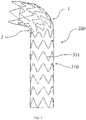
Fig. 2 shows one state of a conventional stent-graft (the outer cover membrane of which is not using a narrow rectangular cover membrane) 300 when it is bent. In thefigure, 1 is the greater curvature side (the side with a larger bending radius) of the stent, and 2 is the lesser curvature side (the side with a smaller bending radius) of the stent. When the stent-graft 300 is bent, the trough of themetal wave ring 311 on themetal stent 310 will upwarp relative to the side wall of the stent, and the upwarping direction is opposite to the direction in which the stent-graft 300 is bent. Viewed from the outside of the stent, on thelesser curvature side 2 of the stent, the troughs of themetal wave ring 311 are embedded to the inner side of the crests of the lower metal wave ring 311 (the side closer to the axis of the stent-graft is the inner side, and the side further away from the axis of the stent-graft is the outer side). Viewed from the lumen of stent, the stacking form of the cover membrane and themetal wave ring 311 at the lumen of the stent is that the troughs of the uppermetal wave ring 311 cover the crests of the lowermetal wave ring 311. Therefore, the stacking form of the cover membrane and themetal wave ring 311 at the lumen of stent is along the blood flow direction. -
Fig. 3 shows the state of the stent-graft 200 with theouter cover membrane 20 using a narrowrectangular membrane 230 when the stent-graft 200 is bent; and when the stent-graft 200 is bent, the exposed trough of the metal wavy rings will upwarp. On thelesser curvature side 2 of the stent, the exposed troughs of the metal wave rings are blocked by the lower narrowstrip cover membrane 230 when tilting upwardly. Therefore, when viewed from the outside of the stent, the troughs of the metal wave ring at thelesser curvature side 2 of the stent cover the crests of the lower metal wave rings. In this case, the stacking form of the cover membrane and the metal wave ring at the lumen of stent is reverse to the blood flow direction, which can easily result in thrombosis, and can also affect the patency of blood flow. - In view of the above problems, it is an object of the present invention to at least solve the problem of thrombosis at the bend that is experienced by the existing stent-graft having an outer membrane using a narrow rectangular membrane. This object is achieved through the following technical solution:
The embodiments of the present invention provide a stent-graft having a proximal greater curvature side and a proximal lesser curvature side. The stent-graft includes a stent body, an inner cover membrane disposed on the inner side of the stent body, and an outer cover membrane disposed on the outer side of the stent body. The stent body includes a plurality of wave rings arranged axially at intervals. Alternatively arranged crests and troughs are formed on the wave rings. The outer cover membrane is provided with a first opening, and the first opening exposes at least one trough located at or nearer to the proximal greater curvature side. - In some embodiments of the present invention, the first opening extends from the proximal lesser curvature side to the proximal greater curvature side, with the height of the first opening gradually increasing from the proximal lesser curvature side to the proximal greater curvature side. The first opening exposes a plurality of troughs located at or nearer to the proximal greater curvature side. Troughs located at the proximal lesser curvature side are all covered by the outer cover membrane.
- In some embodiments of the present invention, the first opening is a circumferentially extending rectangular opening disposed on the proximal greater curvature side, the rectangular opening exposing a plurality of troughs on the same wave ring.
- In some embodiments of the present invention, the length of the first opening in the circumferential direction is one third to two thirds of the length of the outer cover membrane in the circumferential direction.
- In some embodiments of the present invention, there are a plurality of the first openings and they are distributed at and nearer to the proximal greater curvature side, with each of the first openings being a rectangular opening exposing one of the troughs.
- In some embodiments of the present invention, there are a plurality of the first openings and they are distributed at and nearer to the proximal greater curvature side, with each of the first openings being a slit through which one of the troughs protrudes out of the outer cover membrane.
- In some embodiments of the present invention, a second opening is further provided on the outer cover membrane. The second opening is nearer to a distal end of the stent body, and the second opening is a circumferentially extending and end-to-end annular opening. The second opening exposes all the crests on the same wave ring.
- In some embodiments of the present invention, the stent-graft further includes a plurality of reinforcement wires arranged axially at intervals, each of the reinforcement wires being circumferentially wound around the stent body, and the reinforcement wires being positioned to avoid the first opening and the second opening.
- In some embodiments of the present invention, the height of the exposed portion of the wave ring is no more than one third of the height of the wave ring.
- In some embodiments of the present invention, for wave rings having at least a portion exposed, the screw rods on which the crests and troughs are connected are provided with arc-shaped transition sections.
- The advantages of the present invention are that:
According to the stent-graft of the embodiments of the present invention, the outer cover membrane is provided with a first opening, and the first opening exposes at least one trough located at or nearer to the proximal greater curvature side; and the exposed trough can easily hang on a vessel wall, and thereby achieve the function of preventing the stent-graft from shifting. The crests and troughs located at the proximal lesser curvature side of the stent-graft remain covered by the outer cover membrane; the troughs of the wave ring at the proximal lesser curvature side are embedded to the inner side of the crests of the adjacent lower wave ring thereto. Viewed from the stent lumen, the stacking form of the cover membrane and the wave ring at the stent lumen is that the troughs of the upper wave ring cover the crests of the lower wave ring, so that the stack form of the cover membrane and the wave ring at the stent lumen is in the blood flow direction, thereby reducing the risk of thrombosis. In addition, when a conventional stent-graft uses a narrow rectangular cover membrane as the outer cover membrane, since the exposed portion of the metal stent is covered with only the inner cover membrane but lacks the outer cover membrane, it may cause an uneven thickness of the overall cover membrane and the risk of rupture at the position where the membrane thickness is thin. Compared with this stent-graft, the stent-graft of the embodiments of the present invention has relatively lesser exposure of the troughs through the first opening, and it can be understood that when the exposed area of the stent body is smaller, the area of the stent-graft having uneven thickness of the cover membrane is relatively reduced, so that the risk of rupture of the membrane is reduced. - The drawings are only for purposes of illustrating the preferred implementations and are not to be construed as limiting the present invention. And throughout the drawings, like reference numerals represent like components. In the drawings:
-
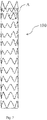
Fig. 1 is a schematic view of a stent-graft with an outer cover membrane using a narrow rectangular cover membrane in the prior art; -
Fig. 2 is a schematic view of a conventional stent-graft in the prior art; -
Fig. 3 is a schematic view of the stent-graft shown inFig. 1 when bent; -
Fig. 4 is a schematic view of a stent-graft according to a first embodiment of the present invention; -
Fig. 5 is a schematic view of the stent-graft shown inFig. 4 when bent; -
Fig. 6 is a schematic view of the stent-graft of the first embodiment of the present invention provided with reinforcement wires; -
Fig. 7 is a schematic view of the stent-graft of the first embodiment of the present invention with arc-shaped transition sections being provided on the screw rod of the wave ring; -
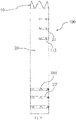
Fig. 8 is an enlarged view of the area A ofFig. 7 ; -
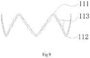
Fig. 9 is a schematic view of the stent-graft according to another embodiment of the present invention with protrusions being provided on the screw rod of the wave ring; -
Fig. 10 is a schematic view of a stent-graft according a second embodiment of the present invention; -
Fig. 11 is a schematic view of a stent-graft according to a third embodiment of the present invention; and -
Fig. 12 is a schematic view of a stent-graft according to a fourth embodiment of the present invention. - Exemplary implementations of the present disclosure will be described in more detail below with reference to the accompanying drawings. Although the drawings show the exemplary implementations of the present disclosure, it should be understood that the present disclosure may be implemented in various forms and should not be limited to the implementations described herein. Instead, these implementations are provided such that the present disclosure can be understood more thoroughly, and can fully convey the scope of the present disclosure to those skilled in the art.
- It should be understood that the terms used herein are for the purpose of describing specific exemplary implementations only, and are not intended to give any limitation. As used herein, the singular forms "a/an", "one" and "the" may also include plural forms, unless the context clearly indicates otherwise. The terms "comprise", "include", "contain" and "have" are inclusive, and indicate the existence of features, steps, operations, elements and/or components stated, but do not exclude the existence or addition of one or more other features, steps, operations, elements, components, and/or combinations thereof. The method steps, processes, and operations described herein are not to be construed as necessarily requiring them to be executed in the particular order described or illustrated, unless the order of execution is explicitly indicated. It should also be understood that additional or alternative steps may be used.
- Although the terms first, second, third, etc., may be used herein to describe a plurality of elements, components, regions, layers and/or sections, these elements, components, regions, layers and/or sections should not be limited by these terms. These terms may be used solely to distinguish one element, component, region, layer or section from another region, layer or section. The terms such as "first", "second", and other numerical terms are not used to imply an order or sequence herein unless it is clearly indicated in the context. Thus, a first element, component, region, layer or section discussed below could be termed a second element, component, region, layer or section without departing from the teachings of the example implementations.
- To facilitate description, spatially relative terms, such as "inside", "outside", "inner", "outer", "under", "below", "over", "above", may be used herein to describe the relationship of an element or feature relative to another element or feature as illustrated. Such spatially relative terms are intended to encompass different orientations of the device in use or in operation in addition to the orientations depicted in the drawings. For example, if a device in a drawing is turned over, elements described as "under other elements or features" or "below other elements or features" would then be oriented as "over other elements or features" or "above other elements or features". Thus, the example term "below" can encompass both an orientation of above and below. The device may be oriented otherwise (rotated by 90 degrees or in other directions) and will be interpreted by the spatially relative descriptors used herein accordingly.
- In addition, when illustrating the implant, it is feasible to define the orientation according to the blood flow direction, and define that the blood flow flows from the proximal end to the distal end; for example, for the stent, it is defined in the present invention that the end where the blood flows in is "proximal end" and the end where the blood flows out is "distal end"; "axial" direction generally refers to the longitudinal direction of the stent as it is delivered.
- As shown in
Figs. 4 and5 , a first embodiment of the present invention provides a stent-graft 100 having a proximalgreater curvature side 110 and a proximallesser curvature side 120, wherein the greater curvature side refers to the side with a larger bending radius and the lesser curvature side refers to the side with a smaller bending radius when the stent-graft 100 is bent after implantation in a blood vessel. Specifically, the stent-graft 100 includes astent body 10, an inner cover membrane (not shown in the figure) disposed on the inner side of thestent body 10, and anouter cover membrane 20 disposed on the outer side of thestent body 10, wherein thestent body 10 includes a plurality of wave rings 11 arranged axially at intervals, and alternating arrangedcrests 111 andtroughs 112 are formed on the wave rings 11, and theouter cover membrane 20 is provided with afirst opening 21, and thefirst opening 21 exposes at least onetrough 112 located at or nearer to the proximalgreater curvature side 110. - It should be noted that, in the present invention, among the inflection points formed on the wave rings 11, the inflection point nearer to the proximal end of the stent-
graft 100 is defined as a crest, and the inflection point nearer to the distal end of the stent-graft 100 is defined as a trough. - According to the stent-
graft 100 according to one embodiment of the present invention, whose form is shown inFig. 5 when it is implanted in the bend position of the thoracic aortic arch, theouter cover membrane 20 of the stent-graft 100 is provided with afirst opening 21, and thefirst opening 21 exposes at least onetrough 112 located at or nearer to the proximalgreater curvature side 110. The exposedtrough 112 can easily hang on a vessel wall, thereby achieving the function of preventing the stent-graft 100 from shifting. The crests and troughs located at the proximallesser curvature side 120 of the stent-graft 100 remain covered by theouter cover membrane 20; and thetroughs 112 of thewave ring 11 at the proximallesser curvature side 120 are embedded to the inner side of thecrests 111 of thelower wave ring 11 adjacent thereto. When viewed from the stent lumen, the stacking form of the cover membrane and wave ring of the stent lumen shows that thetroughs 111 of theupper wave ring 11 cover the crests of thelower wave ring 11, so that the stack form of the cover membrane and thewave ring 11 at the stent lumen is in the blood flow direction, thereby reducing the risk of thrombosis. - In addition, when a stent-graft uses a narrow rectangular cover membrane as the outer cover membrane, since the exposed portion of the metal stent is covered with only the inner cover membrane but lacks the outer cover membrane, it may result in an uneven thickness of the overall cover membrane and there is a risk of rupture at the position where the membrane thickness is thin. Compared with this stent-graft, the stent-
graft 100 of the embodiments of the present invention has relatively less exposure of thetroughs 112 through thefirst opening 21, and it can be understood that when the exposed area of thestent body 10 is smaller, the area of the stent-graft 100 having uneven thickness of the cover membrane is relatively reduced, so that the risk of rupture of the membrane is reduced. - Further, the
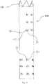
first opening 21 extends from the proximallesser curvature side 120 to the proximalgreater curvature side 110, with the height of thefirst opening 21 gradually increasing from the proximallesser curvature side 120 to the proximalgreater curvature side 110. Thefirst opening 21 exposes a plurality oftroughs 112 located at or nearer to the proximalgreater curvature side 110. Thetroughs 112 located at the proximallesser curvature side 120 are all covered by theouter cover membrane 20. - In the present embodiment, the
first opening 21 extends from the proximallesser curvature side 120 to the proximalgreater curvature side 110, and the height of thefirst opening 21 gradually increases from the proximallesser curvature side 120 to the proximalgreater curvature side 110. Therefore, thefirst opening 21 may be formed by cutting theouter cover membrane 20 covering thestent body 10 along an oblique line, so as to expose thetroughs 112 located at and nearer to the proximalgreater curvature side 110. In addition, this way of forming thefirst opening 21 makes it possible to make the membrane at the proximallesser curvature side 120 thicker and the membrane at the proximalgreater curvature side 110 relatively thinner, thereby making it easier to bend the stent-graft 100 from the proximalgreater curvature side 110 to the proximallesser curvature side 120, and making the stent-graft 100 more flexible. - Further, there may be one or a plurality of the
first openings 21, and when there are a plurality of thefirst openings 21, the plurality of thefirst openings 21 are arranged at intervals in the axial direction of the stent-graft 100. It can be understood that a greater number offirst openings 21 may expose a greater number of wave rings 11 at the proximal end, and thus providing a better anchoring effect of the proximal end of the stent-graft 100 in the blood vessel. - Further, a
second opening 22 is provided on theouter cover membrane 20. Thesecond opening 22 is nearer to a distal end of thestent body 10, and thesecond opening 22 is a circumferentially extending and end-to-end annular opening. Thesecond opening 22 exposes all thecrests 111 on thesame wave ring 11. The distal end of the stent-graft 100 is generally positioned in a straight section of the aortic vessel without significant bending. Therefore, thesecond opening 22 may be formed in such a way that exposes all thecrests 111 of theentire wave ring 11. Thesecond opening 22 is provided for exposing thecrests 111 of thewave ring 11 nearer to the distal end of the stent-graft 100. The exposedcrest 111 can easily hang on a vessel wall, thereby enhancing the anchoring force between the distal end of the stent-graft 100 and the blood vessel, thereby preventing the distal end of the stent-graft 100 from contracting proximally. - Further, there may be one or a plurality of the
second openings 22, and when there are a plurality of thesecond openings 22, the plurality of thesecond openings 22 are arranged at intervals in the axial direction of the stent-graft 100. It can be understood that a greater number ofsecond openings 22 may expose a greater number of wave rings 11 at the distal end, and thereby providing a better anchoring effect of the distal end of the stent-graft 100 in the blood vessel. - Further, the height a of the exposed portion of the
wave ring 11 is no more than one third of the wave ring height c, i.e., a ≤ l/3c, wherein the wave ring height c refers to the dimension of thewave ring 11 in the axial direction of the stent-graft 100 and the height a refers to the dimension of the exposed portion of thewave ring 11 in the axial direction of the stent-graft 100. It can be understood that a greater height c of the exposed portion of thewave ring 11 may cause a smaller contact area between the unexposed portion and theouter cover membrane 20, resulting in an easy shifting of the metal wire constituting thewave ring 11 relative to theouter cover membrane 20. Therefore, limiting the height a of the exposed portion of thewave ring 11 to l/3c reduces the risk of the metal wire shifting relative to theouter cover membrane 20. - Further, as shown in
Fig. 6 , the stent-graft 100 further includes a plurality ofreinforcement wires 30 axially arranged at intervals, each of thereinforcement wires 30 being circumferentially wound around thestent body 10, and thereinforcement wires 30 are provided so as to effectively reinforce the bonding force of thewave ring 11 with theouter cover membrane 20. Especially for thewave ring 11 having an exposed portion, thereinforcement wires 30 are beneficial to prevent thewave ring 11 from shifting relative to theouter cover membrane 20. - Further, the
reinforcement wires 30 are disposed in a manner that avoids thefirst opening 21 and thesecond opening 22. Specifically, thereinforcement wire 30 may be maintained at a distance of 2 mm to 3 mm from the edge of thefirst opening 21 at a position nearer to thefirst opening 21 to ensure that thereinforcement wire 30 will not be exposed beyond theouter cover membrane 20 through thefirst opening 21. Similarly, thereinforcement wire 30 may be maintained at a distance of 2 mm to 3 mm from the edge of thesecond opening 22 at a position nearer to thesecond opening 22 to ensure that thereinforcement wire 30 will not be exposed beyond theouter cover membrane 20 through thesecond opening 22. - Further, the
reinforcement wire 30 may be a PTFE wire, i.e., a wire made of PTFE material. - Further, as shown in
Figs. 7 and8 , for wave rings 11 having at least a portion thereof exposed (including thewave ring 11 havingtrough 112 exposed at the proximal end and thewave ring 11 havingcrest 111 exposed at the distal end), the screw rods on which the crests and troughs are connected are provided withprotrusions 113. In the present embodiment, eachprotrusion 113 is an arc-shaped transition section. For thewave ring 11, except for thecrest 111 andtrough 112, the other portions are straight transitions; after heat treatment of the cover membrane, since there is an exposed portion on thewave ring 11, after the metal wire is combined with the membrane, the force is along the direction of the straight section of the metal wire. Therefore, the force of thewave ring 11 against the shifting of the metal wire relative to the membrane is relatively small, which is easy to cause a shifting problem. In the present embodiment, thewave ring 11 having an exposed portion can be set as an arc section transition with a smaller curvature during heat-setting, thereby increasing the contact area between the metal wire and the cover membrane. In addition, after this structure is covered with the cover membrane, the force exerted by the metal wire on the inner and outer cover membrane is not along the longitudinal direction of the wire, but along the direction of the tangent of the arc section of the metal wire, so as to greatly improve the force against the shifting of the metal wire of thewave ring 11 and the cover membrane, and thereby reduce the risk of shifting between thewave ring 11 and the membrane. It can be understood that the arc-shaped transition sections in the present embodiment are not limited to being formed by braiding, but may be formed by cutting. - Further, as shown in
Fig. 9 , for wave rings 11 having at least a portion exposed (including thewave ring 11 havingtroughs 112 exposed at the proximal end and thewave ring 11 havingcrests 111 exposed at the distal end), the screw rod between thecrest 111 and thetrough 112 is provided with at least oneprotrusion 113. Theprotrusion 113 is used to increase the contact area between the metal wire and the cover membrane, so as to improve the bonding force between the metal wire and the cover membrane, and thereby reduce the risk of shifting of thewave ring 11 and the cover membrane. The shape of theprotrusion 113 is not limited, as long as the contact area between the metal wire and the cover membrane can be increased. Specifically, theprotrusion 113 is not limited to a ring shape, but may be an arc shape, a sphere shape, or the like. In the present embodiment, the specific shape of theprotrusion 113 is formed by cutting. - As shown in
Fig. 10 , a second embodiment of the present invention provides a stent-graft 100 having substantially the same structure as the first embodiment except that the shape of thefirst opening 21 is different. - Specifically, the
second opening 21 is a circumferentially extending rectangular opening disposed on the proximalgreater curvature side 110, the rectangular opening exposing a plurality oftroughs 112 on thesame wave ring 11. Thus, thetroughs 112 at the proximalgreater curvature side 110 may also be exposed, while the crests and troughs at the proximallesser curvature side 120 remain covered by theouter cover membrane 20, thereby reducing the risk of thrombosis. In addition, the stent-graft 100 of the present embodiment can also provide an area which reduces the unevenness of the thickness of the cover membrane to a certain extent, thereby reducing the risk of membrane rupture. - Further, the length of the
first opening 21 in the circumferential direction is one third to two thirds of the length of theouter cover membrane 20 in the circumferential direction, making it possible to obtain both a significant enhancement in the anchoring force of the proximal end of the stent-graft 100 to the blood vessel and an insignificant reduction in the force against shifting between thewave ring 11 and theouter cover membrane 20. - As shown in
Fig. 11 , a third embodiment of the present invention provides a stent-graft 100 having substantially the same structure as the second embodiment except that the shape of thefirst opening 21 is different. - Specifically, there are a plurality of the
first openings 21 and they are distributed along, and nearer to, the proximalgreater curvature side 110, with each of thefirst openings 21 being a rectangular opening exposing one of thetroughs 112. Compared with the second embodiment, the way of disposing thefirst opening 21 in this embodiment can further reduce the area of the portion of thestent body 10 that is not covered by theouter cover membrane 20, thereby further reducing the area of the stent-graft 100 having an uneven thickness of the cover membrane, thereby further reducing the risk of membrane rupture. - As shown in
Fig. 12 , a fourth embodiment of the present invention provides a stent-graft 100 having substantially the same structure as the third embodiment except for further improving the form of thefirst opening 21. - Specifically, there are a plurality of the
first openings 21 and they are distributed along and nearer to the proximalgreater curvature side 110, with each of thefirst openings 21 being a slit through which one of thetroughs 112 protrudes out of theouter cover membrane 20. Compared with the third embodiment, thefirst opening 21 in this embodiment is a slit, and thetrough 112 protrudes out of theouter cover membrane 20 through the slit. In this way, the integrity of theouter cover membrane 20 can be ensured, so that the stent-graft 100 does not form uneven cover membrane thickness, thereby minimizing the risk of membrane rupture. - The above descriptions are merely better specific implementations of the present invention, but the protection scope of the present invention is not limited thereto. Any skilled person who is familiar with this art could readily think of variations or substitutions within the disclosed technical scope of the present invention, and these variations or substitutions shall fall within the protection scope of the present invention. Therefore, the protection scope of the present invention shall be subject to the protection scope of the claims.
Claims (10)
- A stent-graft having a proximal greater curvature side and a proximal lesser curvature side, characterized in that the stent-graft comprises a stent body, an inner cover membrane disposed on an inner side of the stent body, and an outer cover membrane disposed on an outer side of the stent body, wherein the stent body comprises a plurality of wave rings arranged axially at intervals, with alternatively arranged crests and troughs formed on the wave rings, wherein the outer cover membrane is provided with a first opening, and the first opening exposes at least one trough located at or nearer to the proximal greater curvature side.
- The stent-graft of claim 1, characterized in that the first opening extends from the proximal lesser curvature side to the proximal greater curvature side, the height of the first opening gradually increasing from the proximal lesser curvature side to the proximal greater curvature side, the first opening exposing a plurality of troughs located at or nearer to the proximal greater curvature side, and the troughs located at the proximal lesser curvature side are all covered by the outer cover membrane.
- The stent-graft of claim 1, characterized in that the first opening is a circumferentially extending rectangular opening disposed on the proximal greater curvature side, the rectangular opening exposing the plurality of troughs on the same wave ring.
- The stent-graft of claim 3, characterized in that the length of the first opening in the circumferential direction is one third to two thirds of the length of the outer cover membrane in the circumferential direction.
- The stent-graft of claim 1, characterized in that there are a plurality of the first openings and they are distributed at and nearer to the proximal greater curvature side, with each of the first openings being a rectangular opening exposing one of the troughs.
- The stent-graft of claim 1, characterized in that there are a plurality of the first openings and they are distributed at and nearer to the proximal greater curvature side, with each of the first openings being a slit through which one of the troughs protrudes out of the outer cover membrane.
- The stent-graft of claim 1, characterized in that a second opening is further provided on the outer cover membrane, the second opening is nearer to a distal end of the stent body, the second opening is a circumferentially extending and end-to-end annular opening, and the second opening exposes all the crests on the same wave ring.
- The stent-graft of claim 7, characterized in that the stent-graft further comprises a plurality of reinforcement wires arranged axially at intervals, each of the reinforcement wires being circumferentially wound around the stent body, and the reinforcement wires being positioned to avoid the first opening and the second opening.
- The stent-graft of any one of claims 1-8, characterized in that the height of the exposed portion of the wave ring is no more than one third of the height of the wave ring.
- The stent-graft of any one of claims 1-8, characterized in that for the wave rings having at least a portion exposed, screw rods on which the crests and the troughs are connected are provided with protrusions.
Applications Claiming Priority (2)
| Application Number | Priority Date | Filing Date | Title |
|---|---|---|---|
| CN201911223422.4A CN112891019B (en) | 2019-12-03 | 2019-12-03 | Covered stent |
| PCT/CN2020/133175 WO2021110001A1 (en) | 2019-12-03 | 2020-12-01 | Stent graft |
Publications (3)
| Publication Number | Publication Date |
|---|---|
| EP4070764A1 true EP4070764A1 (en) | 2022-10-12 |
| EP4070764A4 EP4070764A4 (en) | 2024-01-17 |
| EP4070764B1 EP4070764B1 (en) | 2026-04-22 |
Family
ID=76104318
Family Applications (1)
| Application Number | Title | Priority Date | Filing Date |
|---|---|---|---|
| EP20896721.6A Active EP4070764B1 (en) | 2019-12-03 | 2020-12-01 | Stent graft |
Country Status (4)
| Country | Link |
|---|---|
| US (1) | US12167957B2 (en) |
| EP (1) | EP4070764B1 (en) |
| CN (1) | CN112891019B (en) |
| WO (1) | WO2021110001A1 (en) |
Families Citing this family (6)
| Publication number | Priority date | Publication date | Assignee | Title |
|---|---|---|---|---|
| JPWO2023127943A1 (en) * | 2021-12-28 | 2023-07-06 | ||
| CN116370142B (en) * | 2021-12-31 | 2026-01-20 | 先健科技(深圳)有限公司 | A covered scaffold |
| CN116919684A (en) * | 2022-04-08 | 2023-10-24 | 上海微创心脉医疗科技(集团)股份有限公司 | Medical support |
| CN115363819B (en) * | 2022-10-27 | 2023-01-31 | 北京华脉泰科医疗器械股份有限公司 | Covered stent and preparation method thereof |
| CN115969591B (en) * | 2022-12-01 | 2025-11-04 | 先健科技(深圳)有限公司 | Lumen stents and stent systems |
| CN121081166A (en) * | 2025-11-07 | 2025-12-09 | 苏州鼎科医疗技术股份有限公司 | Tectorial membrane support |
Family Cites Families (21)
| Publication number | Priority date | Publication date | Assignee | Title |
|---|---|---|---|---|
| US5282823A (en) * | 1992-03-19 | 1994-02-01 | Medtronic, Inc. | Intravascular radially expandable stent |
| US6042605A (en) * | 1995-12-14 | 2000-03-28 | Gore Enterprose Holdings, Inc. | Kink resistant stent-graft |
| US6533807B2 (en) * | 1998-02-05 | 2003-03-18 | Medtronic, Inc. | Radially-expandable stent and delivery system |
| US8382821B2 (en) * | 1998-12-03 | 2013-02-26 | Medinol Ltd. | Helical hybrid stent |
| US6398803B1 (en) * | 1999-02-02 | 2002-06-04 | Impra, Inc., A Subsidiary Of C.R. Bard, Inc. | Partial encapsulation of stents |
| US7186264B2 (en) * | 2001-03-29 | 2007-03-06 | Viacor, Inc. | Method and apparatus for improving mitral valve function |
| US20090099650A1 (en) * | 2001-11-28 | 2009-04-16 | Lee Bolduc | Devices, systems, and methods for endovascular staple and/or prosthesis delivery and implantation |
| CN101283937B (en) * | 2008-05-21 | 2010-08-18 | 微创医疗器械(上海)有限公司 | Tethering methods for open stent grafts |
| CN102488575A (en) * | 2011-11-11 | 2012-06-13 | 许尚栋 | Aortic windowing stent |
| ES2658237T3 (en) * | 2012-02-27 | 2018-03-08 | Hiroshima University | Stent graft |
| CN104434252B (en) | 2013-09-23 | 2017-02-08 | 瑞奇外科器械(中国)有限公司 | End effector, surgical operating instrument and purse-string forceps |
| CN103720529B (en) * | 2013-12-30 | 2017-02-08 | 先健科技(深圳)有限公司 | Arcus aortae intraoperative stent and method for manufacturing stent |
| CN104434352B (en) * | 2014-12-14 | 2016-08-17 | 韩新巍 | A kind of compliance recyclable air flue mushroom covered stent and preparation method thereof |
| FR3045312B1 (en) * | 2015-12-21 | 2020-12-11 | Ludovic Canaud | STENT TYPE AORTIC IMPLANT |
| US10561510B2 (en) * | 2016-06-10 | 2020-02-18 | Medtronic Vascular, Inc. | Customizing the elution profile of a stent |
| CN107536658B (en) * | 2016-06-28 | 2020-12-04 | 上海鸿脉医疗科技有限公司 | Covered stent and manufacturing method thereof |
| CN106344210B (en) * | 2016-11-17 | 2018-05-22 | 浙江归创医疗器械有限公司 | drug-coated stent graft |
| CN208525133U (en) * | 2017-09-07 | 2019-02-22 | 普霖医疗科技(广州)有限公司 | A kind of overlay film frame suitable for dissection of aorta operation |
| EP3733120A4 (en) * | 2017-12-27 | 2021-10-13 | Lifetech Scientific (Shenzhen) Co., Ltd. | COVERED STENT |
| CN110393605B (en) * | 2018-04-23 | 2022-11-04 | 黄健兵 | Aortic arch area branch tectorial membrane support blood vessel composite set |
| CN110393607B (en) * | 2019-07-17 | 2022-04-05 | 深圳市先健畅通医疗有限公司 | stent graft |
-
2019
- 2019-12-03 CN CN201911223422.4A patent/CN112891019B/en active Active
-
2020
- 2020-12-01 EP EP20896721.6A patent/EP4070764B1/en active Active
- 2020-12-01 US US17/774,977 patent/US12167957B2/en active Active
- 2020-12-01 WO PCT/CN2020/133175 patent/WO2021110001A1/en not_active Ceased
Also Published As
| Publication number | Publication date |
|---|---|
| CN112891019A (en) | 2021-06-04 |
| US20220378571A1 (en) | 2022-12-01 |
| EP4070764A4 (en) | 2024-01-17 |
| EP4070764B1 (en) | 2026-04-22 |
| CN112891019B (en) | 2022-09-20 |
| US12167957B2 (en) | 2024-12-17 |
| WO2021110001A1 (en) | 2021-06-10 |
Similar Documents
| Publication | Publication Date | Title |
|---|---|---|
| US12167957B2 (en) | Stent graft | |
| RU2627637C2 (en) | Implanited device for application in human and/or animal body for body valve replacement | |
| CN109419568B (en) | covered stent | |
| CN107441615B (en) | Self-sealing tubular grafts, patches and methods of making and using the same | |
| JP6435262B2 (en) | TREATMENT KIT, TREATMENT DEVICE, AND PRODUCTION METHOD | |
| CN111067664A (en) | stent graft | |
| WO2023140214A1 (en) | Stent | |
| KR102184238B1 (en) | Longitudinal Medical Device | |
| EP3903729B1 (en) | Vascular stent | |
| WO2019128703A1 (en) | Covered stent | |
| US11918452B2 (en) | Covered stent | |
| JP7185739B2 (en) | stent graft | |
| WO2021098578A1 (en) | Dual-layer lumen stent | |
| JP7771046B2 (en) | stent graft | |
| WO2022183955A1 (en) | Reinforcing rib for stent graft and stent graft system | |
| CN109730805B (en) | Branch type blood vessel support | |
| CN113893062B (en) | Covered stent | |
| US20180116782A1 (en) | Stent graft | |
| CN215458977U (en) | Blood vessel support | |
| CN113476176A (en) | Blood vessel support | |
| JP4429833B2 (en) | Stent and stent graft | |
| CN119302783A (en) | Intraluminal implant, suturing method and vascular plug system | |
| CN206934211U (en) | Branch type overlay film frame | |
| CN114642526B (en) | Covered stent | |
| KR20140068092A (en) | Self-expandable double plastic stent |
Legal Events
| Date | Code | Title | Description |
|---|---|---|---|
| STAA | Information on the status of an ep patent application or granted ep patent |
Free format text: STATUS: THE INTERNATIONAL PUBLICATION HAS BEEN MADE |
|
| PUAI | Public reference made under article 153(3) epc to a published international application that has entered the european phase |
Free format text: ORIGINAL CODE: 0009012 |
|
| STAA | Information on the status of an ep patent application or granted ep patent |
Free format text: STATUS: REQUEST FOR EXAMINATION WAS MADE |
|
| 17P | Request for examination filed |
Effective date: 20220627 |
|
| AK | Designated contracting states |
Kind code of ref document: A1 Designated state(s): AL AT BE BG CH CY CZ DE DK EE ES FI FR GB GR HR HU IE IS IT LI LT LU LV MC MK MT NL NO PL PT RO RS SE SI SK SM TR |
|
| DAV | Request for validation of the european patent (deleted) | ||
| DAX | Request for extension of the european patent (deleted) | ||
| A4 | Supplementary search report drawn up and despatched |
Effective date: 20231218 |
|
| RIC1 | Information provided on ipc code assigned before grant |
Ipc: A61F 2/07 20130101ALI20231212BHEP Ipc: A61F 2/06 20130101ALI20231212BHEP Ipc: A61F 2/82 20130101AFI20231212BHEP |
|
| RAP1 | Party data changed (applicant data changed or rights of an application transferred) |
Owner name: LIFETECH SCIENTIFIC (SHENZHEN) CO., LTD. |
|
| RAP1 | Party data changed (applicant data changed or rights of an application transferred) |
Owner name: LIFETECH SCIENTIFIC (SHENZHEN) CO., LTD. |
|
| GRAP | Despatch of communication of intention to grant a patent |
Free format text: ORIGINAL CODE: EPIDOSNIGR1 |
|
| STAA | Information on the status of an ep patent application or granted ep patent |
Free format text: STATUS: GRANT OF PATENT IS INTENDED |
|
| INTG | Intention to grant announced |
Effective date: 20251202 |
|
| P01 | Opt-out of the competence of the unified patent court (upc) registered |
Free format text: CASE NUMBER: UPC_APP_0002277_4070764/2026 Effective date: 20260122 |
|
| GRAS | Grant fee paid |
Free format text: ORIGINAL CODE: EPIDOSNIGR3 |
|
| GRAA | (expected) grant |
Free format text: ORIGINAL CODE: 0009210 |
|
| STAA | Information on the status of an ep patent application or granted ep patent |
Free format text: STATUS: THE PATENT HAS BEEN GRANTED |
|
| AK | Designated contracting states |
Kind code of ref document: B1 Designated state(s): AL AT BE BG CH CY CZ DE DK EE ES FI FR GB GR HR HU IE IS IT LI LT LU LV MC MK MT NL NO PL PT RO RS SE SI SK SM TR |
|
| REG | Reference to a national code |
Ref country code: CH Ref legal event code: F10 Free format text: ST27 STATUS EVENT CODE: U-0-0-F10-F00 (AS PROVIDED BY THE NATIONAL OFFICE) Effective date: 20260422 Ref country code: GB Ref legal event code: FG4D |
|
| REG | Reference to a national code |
Ref country code: DE Ref legal event code: R096 Ref document number: 602020070931 Country of ref document: DE |