EP4070494B1 - Joint channel state information for virtual user equipment - Google Patents
Joint channel state information for virtual user equipment Download PDFInfo
- Publication number
- EP4070494B1 EP4070494B1 EP20825360.9A EP20825360A EP4070494B1 EP 4070494 B1 EP4070494 B1 EP 4070494B1 EP 20825360 A EP20825360 A EP 20825360A EP 4070494 B1 EP4070494 B1 EP 4070494B1
- Authority
- EP
- European Patent Office
- Prior art keywords
- joint
- base station
- uecs
- channel state
- indication
- Prior art date
- Legal status (The legal status is an assumption and is not a legal conclusion. Google has not performed a legal analysis and makes no representation as to the accuracy of the status listed.)
- Active
Links
Images




Classifications
-
- H—ELECTRICITY
- H04—ELECTRIC COMMUNICATION TECHNIQUE
- H04L—TRANSMISSION OF DIGITAL INFORMATION, e.g. TELEGRAPHIC COMMUNICATION
- H04L5/00—Arrangements affording multiple use of the transmission path
- H04L5/0001—Arrangements for dividing the transmission path
- H04L5/0014—Three-dimensional division
- H04L5/0023—Time-frequency-space
-
- H—ELECTRICITY
- H04—ELECTRIC COMMUNICATION TECHNIQUE
- H04B—TRANSMISSION
- H04B7/00—Radio transmission systems, i.e. using radiation field
- H04B7/02—Diversity systems; Multi-antenna system, i.e. transmission or reception using multiple antennas
- H04B7/04—Diversity systems; Multi-antenna system, i.e. transmission or reception using multiple antennas using two or more spaced independent antennas
- H04B7/06—Diversity systems; Multi-antenna system, i.e. transmission or reception using multiple antennas using two or more spaced independent antennas at the transmitting station
- H04B7/0613—Diversity systems; Multi-antenna system, i.e. transmission or reception using multiple antennas using two or more spaced independent antennas at the transmitting station using simultaneous transmission
- H04B7/0615—Diversity systems; Multi-antenna system, i.e. transmission or reception using multiple antennas using two or more spaced independent antennas at the transmitting station using simultaneous transmission of weighted versions of same signal
- H04B7/0619—Diversity systems; Multi-antenna system, i.e. transmission or reception using multiple antennas using two or more spaced independent antennas at the transmitting station using simultaneous transmission of weighted versions of same signal using feedback from receiving side
- H04B7/0621—Feedback content
- H04B7/0626—Channel coefficients, e.g. channel state information [CSI]
-
- H—ELECTRICITY
- H04—ELECTRIC COMMUNICATION TECHNIQUE
- H04B—TRANSMISSION
- H04B7/00—Radio transmission systems, i.e. using radiation field
- H04B7/02—Diversity systems; Multi-antenna system, i.e. transmission or reception using multiple antennas
- H04B7/022—Site diversity; Macro-diversity
- H04B7/026—Co-operative diversity, e.g. using fixed or mobile stations as relays
-
- H—ELECTRICITY
- H04—ELECTRIC COMMUNICATION TECHNIQUE
- H04B—TRANSMISSION
- H04B7/00—Radio transmission systems, i.e. using radiation field
- H04B7/02—Diversity systems; Multi-antenna system, i.e. transmission or reception using multiple antennas
- H04B7/04—Diversity systems; Multi-antenna system, i.e. transmission or reception using multiple antennas using two or more spaced independent antennas
- H04B7/06—Diversity systems; Multi-antenna system, i.e. transmission or reception using multiple antennas using two or more spaced independent antennas at the transmitting station
- H04B7/0613—Diversity systems; Multi-antenna system, i.e. transmission or reception using multiple antennas using two or more spaced independent antennas at the transmitting station using simultaneous transmission
- H04B7/0615—Diversity systems; Multi-antenna system, i.e. transmission or reception using multiple antennas using two or more spaced independent antennas at the transmitting station using simultaneous transmission of weighted versions of same signal
- H04B7/0619—Diversity systems; Multi-antenna system, i.e. transmission or reception using multiple antennas using two or more spaced independent antennas at the transmitting station using simultaneous transmission of weighted versions of same signal using feedback from receiving side
- H04B7/0621—Feedback content
- H04B7/0628—Diversity capabilities
-
- H—ELECTRICITY
- H04—ELECTRIC COMMUNICATION TECHNIQUE
- H04L—TRANSMISSION OF DIGITAL INFORMATION, e.g. TELEGRAPHIC COMMUNICATION
- H04L1/00—Arrangements for detecting or preventing errors in the information received
- H04L1/0001—Systems modifying transmission characteristics according to link quality, e.g. power backoff
- H04L1/0023—Systems modifying transmission characteristics according to link quality, e.g. power backoff characterised by the signalling
- H04L1/0026—Transmission of channel quality indication
-
- H—ELECTRICITY
- H04—ELECTRIC COMMUNICATION TECHNIQUE
- H04L—TRANSMISSION OF DIGITAL INFORMATION, e.g. TELEGRAPHIC COMMUNICATION
- H04L5/00—Arrangements affording multiple use of the transmission path
- H04L5/003—Arrangements for allocating sub-channels of the transmission path
- H04L5/0048—Allocation of pilot signals, i.e. of signals known to the receiver
-
- H—ELECTRICITY
- H04—ELECTRIC COMMUNICATION TECHNIQUE
- H04L—TRANSMISSION OF DIGITAL INFORMATION, e.g. TELEGRAPHIC COMMUNICATION
- H04L5/00—Arrangements affording multiple use of the transmission path
- H04L5/003—Arrangements for allocating sub-channels of the transmission path
- H04L5/0053—Allocation of signalling, i.e. of overhead other than pilot signals
- H04L5/0057—Physical resource allocation for CQI
-
- H—ELECTRICITY
- H04—ELECTRIC COMMUNICATION TECHNIQUE
- H04L—TRANSMISSION OF DIGITAL INFORMATION, e.g. TELEGRAPHIC COMMUNICATION
- H04L5/00—Arrangements affording multiple use of the transmission path
- H04L5/0091—Signalling for the administration of the divided path, e.g. signalling of configuration information
- H04L5/0094—Indication of how sub-channels of the path are allocated
-
- H—ELECTRICITY
- H04—ELECTRIC COMMUNICATION TECHNIQUE
- H04B—TRANSMISSION
- H04B7/00—Radio transmission systems, i.e. using radiation field
- H04B7/02—Diversity systems; Multi-antenna system, i.e. transmission or reception using multiple antennas
- H04B7/04—Diversity systems; Multi-antenna system, i.e. transmission or reception using multiple antennas using two or more spaced independent antennas
- H04B7/0413—MIMO systems
- H04B7/0417—Feedback systems
-
- H—ELECTRICITY
- H04—ELECTRIC COMMUNICATION TECHNIQUE
- H04L—TRANSMISSION OF DIGITAL INFORMATION, e.g. TELEGRAPHIC COMMUNICATION
- H04L1/00—Arrangements for detecting or preventing errors in the information received
- H04L1/0001—Systems modifying transmission characteristics according to link quality, e.g. power backoff
- H04L1/0023—Systems modifying transmission characteristics according to link quality, e.g. power backoff characterised by the signalling
- H04L1/0028—Formatting
- H04L1/0031—Multiple signaling transmission
-
- H—ELECTRICITY
- H04—ELECTRIC COMMUNICATION TECHNIQUE
- H04L—TRANSMISSION OF DIGITAL INFORMATION, e.g. TELEGRAPHIC COMMUNICATION
- H04L5/00—Arrangements affording multiple use of the transmission path
- H04L5/003—Arrangements for allocating sub-channels of the transmission path
- H04L5/0058—Allocation criteria
- H04L5/006—Quality of the received signal, e.g. BER, SNR, water filling
Definitions
- This disclosure relates generally to wireless communications and, more particularly, to grouping strategies for coordinating user devices in wireless communication systems.
- a base station In wireless communication systems, such as fifth-generation (5G) radio access (“NR”) networks, a base station (e.g., a gNB) must configure downlink and uplink transmissions to and from user devices within the base station's coverage area. To perform this configuration, the base station transmits control information indicating random access channel information, scheduling grants, power control commands, coding information, etc. via a control channel.
- control information indicating random access channel information, scheduling grants, power control commands, coding information, etc. via a control channel.
- handling the configuration of a large number of user devices can require extensive control channel overhead (e.g., time and frequency resources), leading to a reduction in network efficiency.
- the signal strength at the location of a particular user device (commonly referred to as a user equipment ("UE")) and/or the reception capability of a particular UE may be poor.
- the UE may be located at a cell edge or experiencing fading effects due to Doppler shift, multipath propagation, or shadowing.
- the base station may struggle to establish communication with the UE, further diminishing overall network efficiency.
- WO 2016/120686 A1 relates to coordinating device-to-device communications amongst a plurality of devices.
- the document states that the helper UE device may be able to send a single CQI value and/or single CSI value for the collective channel.
- one or more of the UE devices may determine a CQI or CSI value defined based on the plurality of channels (between each device and the RRH) and their qualities when the devices are helping each other.
- a number of UEs form a group (referred to herein as a "UE Coordination Set” or "UECS") that a base station views-at least in some respects and at some protocol stack layers-as a single UE or “virtual" UE.
- UECS UE Coordination Set
- the base station of the serving cell is unaware of changing joint reception capabilities of the UE group (or UECS, as the UE group is referred to herein) over time (e.g., as particular UEs experience poor channel conditions)
- the techniques of this disclosure provide feedback to the base station that the base station can use to quickly adapt downlink transmissions to suit current capabilities of the UECS.
- a coordinating or "master" UE of the UECS collects individual reception capability information from each UE in the UECS.
- the capability information may indicate how many multiple-input, multiple-output (MIMO) layers the UE can process, and possibly other information (e.g., whether the UE can perform non-linear processing on a received MIMO signal).
- MIMO multiple-input, multiple-output
- a UE with two antennas may report a 2-layer, 2x2 MIMO processing capability.
- the master UE analyzes the individual UE capabilities to determine a joint capability for the UECS, which the master UE reports to the base station.
- the master UE may report a 4-layer MIMO processing capability for the UECS.
- the same two UEs may only be able to support single-input, single-output (SISO) processing under their current channel conditions, and the master consequently reports a 2-layer MIMO processing capability for the UECS.
- the master UE then distributes the joint capability information to the other UEs in the UECS to enable joint transmission from the UECS to the base station.
- the base station Based on the received joint capability information of the UECS, the base station defines/determines a channel state information (CSI) process configuration that is specific to the UECS.
- the CSI process configuration includes, for example, timing and frequency information for a reference signal (e.g., for a CSI-RS) that the base station will send to the UECS.
- the CSI process configuration may also include other information needed for the CSI process, such as code domain information (e.g., for signal pre-coding).
- the base station transmits a control signal (e.g., a radio resource control (RRC) message, or a lower layer message) including the CSI process configuration to the UECS.
- RRC radio resource control
- the UECS jointly receives the control signal, and the UEs process the CSI process configuration in order to, for example, identify the time and frequency resources on which the UEs are to receive the reference signal.
- the base station defines resources for, and transmits, multiple reference signals (e.g., one per base station antenna).
- the base station transmits the reference signal to the UECS, and each of the UEs performs measurements on the received reference signal to determine UE-specific channel quality and generate a UE-specific CSI report.
- Each UE-specific CSI report may include parameters such as a channel quality indicator (CQI), a precoding matrix indicator (PMI), a rank indicator (RI), and/or a modulation and coding scheme (MCS) index.
- CQI channel quality indicator
- PMI precoding matrix indicator
- RI rank indicator
- MCS modulation and coding scheme
- the UEs in the UECS forward their respective individual CSI reports to the master UE, which then calculates a joint CSI report for the UECS as a whole.
- the joint CSI report may include the same types of parameters as the individual CSI reports, for example.
- the parameters include parameters that indicate how many streams, or MIMO layers, the base station should use.
- one or more parameters in the joint CSI report may depend on certain joint processing capabilities of the UECS. For example, if the UECS only includes UEs that are capable of linear joint processing, then the master UE may report a lower/worse joint CQI (in the joint CSI report) than would be the case if at least one UE were capable of non-linear joint processing.
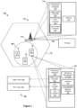
- Fig. 1 illustrates an example communication system 100 in which joint channel state feedback techniques for a User Equipment Coordination Set (UECS) of this disclosure can be implemented.
- the communication system 100 includes a number of user equipment (UE), including UE 102, UE 104, and UE 106.
- UE user equipment
- Each of UEs 102, 104, and 106 can be any suitable device capable of wireless communication (e.g., any of the exemplary user devices discussed below after the description of the figures).
- the UEs 102, 104, and 106 form a UE group 108, also referred to herein as a UECS 108.
- Fig. 1 depicts three UEs, the UECS 108 may include any number (greater than one) of UEs.
- the UECS 108 can locally coordinate uplink (UL) transmission and downlink (DL) reception to and from a base station 114, using techniques described in further detail below.
- the base station 114 is communicatively connected to a core network (CN) 110 via an NG interface, for example.
- the base station 114 is a 5G New Radio (NR) base station operating as a g Node B (gNB), and the CN 110 is a 5G core network (5GC).
- the communication system 100 can include one or more base stations that operate according to radio access technologies (RATs) of types other than NR, and these base stations can be connected to CNs of other types.
- the CN 110 can be, for example, a 5G core network (5GC), a less advanced core network (e.g., an evolved packet core (EPC)), or, conversely, a more advanced core network.
- 5GC 5G New Radio
- EPC evolved packet core
- the base station 114 is associated with a RAN 112 and provides coverage to a cell 116. While Fig. 1 depicts the base station 114 as associated with only one cell 116, it is understood that the base station 114 may also cover one or more additional cells not shown in Fig. 1 . Further, the RAN 112 can include any suitable number of base stations that collectively support one or more RATs. Each UE, such as the UE 102, can communicatively connect with the RAN 112 via the base station 114 when operating within the cell 116, and in turn can communicatively connect with the CN 110 via the RAN 112.
- the UE 102 is equipped with at least processing hardware 130, a UE group management unit 136, at least one antenna 140, and a local wireless network interface 150. While Fig. 1 depicts only the UE 102 as including the processing hardware 130, the UE group management unit 136, the antenna 140, and the local wireless network 150, it is understood that each of the UEs 104 and 106 also include the same or similar elements.
- the processing hardware 130 can include one or more general-purpose processors (e.g., CPUs) and at least one non-transitory computer-readable memory storing instructions executable on the one or more general processors and/or special-purpose processing units, such as a wireless communication chipset.
- the processing hardware 130 includes a physical (PHY) layer controller 132.
- the PHY layer controller 132 is responsible for internal procedures at a PHY layer 182 of a wireless communication protocol stack 180, such as demodulating and decoding downlink control and data signals received from a base station (e.g., the base station 114), encoding and modulating uplink control and data signals, and so on.
- the PHY layer controller 132 includes a channel state information (CSI) controller 133.
- the CSI may conform to the CSI defined by current standards (e.g., 3GPP Technical Specifications 36.312 and/or 38.312), or may correspond to channel state information more generally.
- the CSI controller 133 supports functions related to determining reception capability information, joint reception capability information, CSI reports, and/or joint CSI reports, as described below with reference to Figs. 3A-4 .
- the processing hardware 130 also includes an upper layer controller 134.
- the upper layer controller 134 is responsible for internal procedures at a corresponding upper layer 184 above the PHY layer 182 of the protocol stack 180, such as aggregating uplink data and disaggregating downlink data for the UECS 108.
- the upper layer 184 may be, for example, a medium access control (MAC) layer, a packet data convergence protocol (PDCP) layer, or a radio link control (RLC) layer.
- the upper layer controller 134 may support channel access, addressing, quality of service (QoS) and other functions of a MAC layer, user plane data transfer, control plane data transfer, integrity protection and other functions of a PDCP layer, or segmentation and other functions of an RLC layer.
- the processing hardware 130 may also include a controller for each of a number of other layers, such as a Radio Resource Control (RRC) controller and a mobility management (MM) controller associated with RRC and MM layers of the protocol stack 180, respectively.
- RRC Radio Resource Control
- the UE group management unit 136 of the UE 102 is generally responsible for functions related to UE grouping functions, such as sharing signals with the other UEs of the UECS 108 (e.g., the UEs 104 and 106) as discussed further below.
- the UEs of the UECS 108 may communicate with each other over at least one local wireless network, which is not depicted in Fig. 1 .
- the local wireless network may correspond to a personal area network (PAN), near-field communication (NFC), Bluetooth TM , wireless local area network (WLAN), or any other suitable communication standard(s) or protocol(s).
- the local wireless network interface 150 of the UE 102 generally facilitates communications with the other UEs of the UECS 108 on the local wireless network.
- the UE group management unit 136 may be jointly implemented by the processing hardware 130 and the local wireless network interface 150, or may be implemented by another controller of the UE 102 that is not shown in Fig. 1 .
- the base station 114 includes at least one antenna 170 to communicate with the other elements of the communication system 100.
- the base station 114 also includes processing hardware 160, which can include one or more general-purpose processors (e.g., CPUs) and at least one non-transitory computer-readable memory storing instructions executable on the one or more general processors and/or special-purpose processing units, such as a wireless communication chipset. Similar to the processing hardware 130 of the UE 102, the processing hardware 160 can include a PHY layer controller 162 and an upper layer controller 164 corresponding to the PHY layer 182 and upper layer 184, respectively, of the protocol stack 180.
- general-purpose processors e.g., CPUs
- the processing hardware 160 can include a PHY layer controller 162 and an upper layer controller 164 corresponding to the PHY layer 182 and upper layer 184, respectively, of the protocol stack 180.
- Controllers 162 and 164 may perform similar or corresponding functions as controllers 132 and 134, but from the perspective of the base station 114 rather than the UE 102.
- the PHY layer controller 162 may encode and modulate downlink control and data signals transmitted to the UECS 108
- the upper layer controller 164 may aggregate downlink data for the UECS 108 and disaggregate uplink data received from the UECS 108..
- the PHY layer controller 162 includes a CSI process controller 163.
- the CSI process controller 163 may perform similar functions as the CSI controller 133, but from the perspective of the base station 114 rather than the UE 102.
- the CSI process controller 163 defines CSI process configurations that the base station 114 will transmit to the UECS 108, as described below with reference to Figs. 3B and 4 .
- the upper layer controllers 134 and 164, PHY layer controllers 132 and 162, CSI controller 133 and CSI process controller 163, and UE group management unit 136 can each be implemented using any suitable combination of hardware, software, and/or firmware.
- the controllers 132, 133, 134, 162, 163, and 164 and/or the UE group management unit 136 are a set of instructions that the respective processing hardware 130 or 160 executes to perform the various functions described herein.
- the UE 102 includes at least one antenna 140, for receiving signals transmitted to the UE 102 and transmitting signals from the UE 102.
- the UE 102 may be equipped with multiple antennas 140 to support multiple-input, multiple-output (MIMO) communications, or with only a single antenna 140.
- MIMO multiple-input, multiple-output
- the UE 102 may have two transmit-receive antennas to support two simultaneous transmission/reception paths, or may have separate transmit and receive antennas, etc.
- MIMO communication between the base station 114 and the UEs 102, 104 is discussed below with reference to Fig. 2 .
- the base station 114 e.g., the PHY controller 162 may determine an antenna port at the PHY layer 182 for each physical antenna 140 of the UE 102.
- the UEs 102, 104, and 106, and possibly other UEs not depicted in Fig. 1 form the UECS 108.
- the UECS 108 may be formed in a variety of ways, depending on the implementation and/or scenario. In some implementations, for example, UEs can locally coordinate with each other, with little or no input from the base station 114, to form the UECS 108. The UEs 102, 104, and 106 can choose to coordinate with each other based on, for example, their respective distances from each other, and/or based on other suitable factors.
- the UEs 102, 104 and 106 may jointly select a coordinating or "master" UE from among the UEs 102, 104 and 106, for example, based on the relative processing capabilities of the UEs 102, 104 and 106 and/or other factors (e.g., proximity to the base station 114).
- the base station 114 directs or partially directs formation of the UECS 108.
- the base station 114 detects the UEs 102, 104, and 106 within the cell 116, and assigns each UE to the UECS 108.
- the base station 114 may also request that the UEs 102, 104 and 106 form the UECS 108, and only assign a particular UE to the UECS 108 if that UE responds with an acknowledgement and/or approval of the request.
- the base station 114 may select UEs for the UECS 108 based on the location of each UE relative to the base station 114 and to the other UEs, and/or other factors.
- the base station 114 may also select certain UEs for the UECS 108 depending on beam scheduling, for example, with the base station 114 only selecting UEs that are in the same beam. The base station 114 may also select which single UE is to function as the master UE of the UECS 108.
- the UECS 108 can jointly receive downlink control and data signals from the base station 114, and jointly transmit uplink control and data signals to the base station 114. Because each UE of the UECS 108 is equipped with at least one antenna (e.g., the antenna 140 of the UE 102), the UECS 108 can utilize the antennas of the individual UEs as a distributed antenna arrangement for both reception and transmission. Accordingly, the UECS 108 can have reception and transmission capabilities that exceed those of the individual UEs 102, 104, and 106.
- the UECS 108 can leverage the combined processing power of the UEs 102, 104, and 106 to demodulate data and control signals, thereby improving reception for the UECS 108 as a whole.
- the master UE may function as a "joint-receiver" UE to perform the functions necessary to facilitate joint reception, or the master UE may delegate that responsibility by assigning another UE to be the joint-receiver UE.
- the base station 114 directs the master UE to select a joint-receiver UE, or directly assigns the joint-receiver UE.
- the master UE selects a joint-receiver UE with little or no input from the base station.
- the master UE may change which UE acts as the joint-receiver UE depending on changing power and reception conditions and/or capabilities of the UEs in the UECS 108. Regardless of how the joint-receiver UE is selected, or re-assigned, the joint-receiver UE may facilitate joint reception using any of the various techniques described below with respect to Figs. 3B-4 .
- the UECS 108 and base station 114 take advantage of the distributed antenna arrangement of the UEs by implementing multiple-input, multiple-output (MIMO) communications for the uplink and/or downlink.
- MIMO communications can improve data rates (with spatial multiplexing, i.e., transmitting different data from different antennas) or error rates (with spatial diversity, i.e., transmitting redundant data on different antennas), for both the uplink and downlink.
- the base station 114 includes four transmit-receive antennas 202, 204, 206, and 208 each having its own transmit/receive circuitry in the radio frequency (RF) front end
- the UE 102 includes two transmit-receive antennas 210 and 212 each having its own transmit/receive circuitry in the RF front end
- the UE 104 also includes two transmit-receive antennas 214 and 216 each having its own transmit/receive path in the RF front end.
- each of the UEs 102 and 104 can support two downlink and two uplink streams, corresponding to two MIMO layers (2x2 MIMO communication).
- the base station 114 using its four transmit-receive antennas, can support four MIMO layers. While a single one of the UEs 102, 104 is only capable of 2x2 MIMO communication with the base station 114, the UEs 102 and 104 combined, as the UECS 108, are capable of 4x4 communication with the base station 114. It is understood that the UEs 102 and 104, and/or the base station 114, may instead have more or fewer antennas than are depicted in Fig. 2 , thereby supporting more or fewer MIMO layers.
- the base station 114 To configure MIMO communications with the UECS 108, the base station 114 first determines the total number of antennas the UECS 108 (i.e., the UEs 102 and 104) has available, and the signal quality of the different streams between the UECS 108 and the base station 114. It is understood that references made herein to the number of different antennas of a UE or base station may mean the number of physical antennas, or may mean the number of antennas or antenna sets that are coupled to different RF front ends.
- a combination of a patch antenna and a monopole antenna at a UE or base station may "count" as only one antenna if both antennas are coupled to the same RF front end (e.g., for purposes of generating a particular antenna radiation pattern).
- the base station 114 determines how to configure MIMO communications with a UE (e.g., the UE 102) based on CSI received from the UE 102.
- the base station 114 similarly defines a CSI process configuration that indicates time and frequency resources that the base station 114 will use to transmit a reference signal (e.g., a CSI-RS) to the UECS 108.
- a reference signal e.g., a CSI-RS
- the UE 102 can use (e.g., perform measurements on) the reference signal to estimate various parameters relating to channel quality and to estimate suitable MIMO or SISO configurations for the downlink, and transmits this information to the base station 114 in a CSI report.
- Parameters included in the CSI report indicate how well the UE 102 (and more specifically, the antennas of UE 102) is currently able to receive from the base station 114 (i.e., as a result of the channel conditions currently experienced at the antennas of the UE 102).
- the CSI report can include indications of how many streams, or MIMO layers, the UE 102 can currently process, thereby indicating a number of antennas of the UE 102 that are available for reception.
- Examples of the parameters that the UE 102 can include in the CSI report include a channel quality indicator (CQI), a rank indicator (RI), and a precoding matrix indicator (PMI).
- the CQI may indicate a modulation and coding scheme (MCS) (e.g., by including an MCS index).
- MCS modulation and coding scheme
- the RI specifies a suggested number of MIMO layers the base station 114 should use when transmitting to the UE 102, and is based on the number of antennas the UE 102 has available to receive MIMO streams.
- the PMI may suggest a suitable MIMO precoding matrix for the specified RI
- the CQI may specify a modulation and coding scheme (MCS) suitable for the specified PMI.
- the CSI report can also include a CSI-RS resource indicator (CRI) to identify a beam the CSI report is based on (for example, if the base station 114 transmits reference signals on multiple beams).
- CRI CSI-RS resource indicator
- the UE 102 also can include in the CSI report a layer indicator (LI) to notify the base station 114 which MIMO layer the UE 102 has identified as the best one, as well as a Synchronization Signal Block (SSB) Physical Broadcast Channel (PBCH) Block Resource Indicator (SSBRI) and layer 1 reference signal received power (L1-RSRP), which the base station 114 can use in beam management and mobility procedures.
- LI layer indicator
- SSB Synchronization Signal Block
- PBCH Physical Broadcast Channel
- SSBRI Block Resource Indicator
- L1-RSRP layer 1 reference signal received power
- the base station 114 transmits a reference signal to each of the UEs 102 and 104 in accordance with a CSI process configuration defined by the base station 114 for each of the UEs 102 and 104 (i.e., with different time/frequency resources for the two reference signals).
- a CSI process configuration defined by the base station 114 for each of the UEs 102 and 104 (i.e., with different time/frequency resources for the two reference signals).
- Each of the UEs 102 and 104 receives its respective reference signal, processes the respective reference signal, and transmits a UE-specific CSI-report (i.e., corresponding only to the individual UE) to the base station 114.
- the base station 114 can define a single CSI process configuration for the UECS 108 as a whole, and transmit a reference signal in accordance with the CSI process configuration defined for the group.
- the UECS 108 can jointly receive and process the control signal including the CSI process configuration, and each UE can receive and process (e.g., perform measurements on) the reference signal.
- the UECS 108 determines a joint CSI report, which may (depending on current channel conditions for each UE) reflect a greater reception capability than is possible for any individual UE.
- the UEs of the UECS 108 can determine a joint CSI report based on the joint reception capability of the group, and transmit the joint CSI report together to the base station 114. While Figs. 3A-7 and the accompanying descriptions refer specifically to the UEs 102, 104, 106, the UECS 108, and the base station 114 of Fig. 1 , it is understood that the following techniques may be implemented by other components and/or in systems other than the communication system 100 of Fig. 1 .
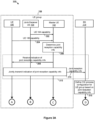
- Figs. 3A and 3B together illustrate a messaging diagram of a first example scenario 300 in which the UEs of the UECS 108 transmit joint reception capability and state information of the UECS 108 to the base station 114.
- the UE 102 is acting as the master UE of the UECS 108
- the UE 104 is acting as the joint-receiver UE 104 of the UECS 108
- the UE 106 is another UE in the UECS 108 that is neither the master nor the joint-receiver.
- the UEs 102, 104, and/or 106 can have other roles within the UECS 108.
- the master UE 102 does not assign a joint-receiver UE, and instead performs the joint-reception functions.
- the example scenario 300 begins when a UE in a UECS 108, such as the joint-receiver UE 104, transmits 302 its own UE-specific reception capability information to the master UE 102 via a local wireless network (e.g., the local wireless network discussed above in connection with Fig. 1 ).
- the UE-specific reception capability information may indicate, for example, how many MIMO layers the UE can process, or can currently process under current channel conditions. For example, a UE with two antennas can report a 2-layer, 2x2 MIMO processing capability.
- UE-specific reception capability information indicates that the corresponding UE only supports SISO processing.
- the UE-specific reception capability information also indicates whether the UE can perform linear or non-linear processing on a received MIMO (or SISO) signal. More generally, the UE-specific reception capability information may indicate a number of antennas of the UE, or include an indication of a number of antenna ports the base station 114 can determine for the UE. Further, the UE-specific reception capability information reported by each UE may be specific to each of one or more carrier frequency bands. For instance, a UE may report a first number of MIMO layers available for processing signals carried on a first band (e.g., low band), and a second, different number of MIMO layers available for processing signals carried on a different, second band (e.g., mid band).
- a first band e.g., low band
- second band e.g., mid band
- Another UE such as UE 106, may also transmit 304 its UE-specific reception capability information to the master UE 102 via the local wireless network. While Fig. 3A depicts the UE 106 as transmitting 304 its UE-specific reception capability information after the joint-receiver UE 104, the relative timing of the transmissions differ from what is shown. For example, the UE 106 may transmit 304 its information prior to, or at the same time that, the joint-receiver UE 104 transmits 302 its information.
- the master UE 102 may instead receive the UE-specific reception capability information from the UEs 104 and 106 in other ways.
- the UE 106 may first transmit its UE-specific reception capability information to the joint-receiver UE 104 or another UE of the UECS 108, and the joint-receiver UE 104 or other UE may forward the information corresponding to the UE 106 to the master UE 102 (e.g., that information alone, or grouped with the UE-specific reception capability information of the forwarding UE).
- Such scenarios can occur, for example, if the UE 106 has a poor wireless local connection with the master UE 102 but can communicate better with the joint-receiver UE 104 or another UE of the UECS 108 perhaps using a different wireless local communication technology such as Bluetooth TM .
- the UE-specific reception capability information of a particular UE may be transmitted through several UEs of the UECS 108 before it reaches the master UE 102, depending on channel conditions and the capabilities of the respective UEs.
- the master UE 102 determines 306 joint reception capability information corresponding to the reception capability of the UECS 108 as a whole (i.e., when jointly receiving signals from the BS 114). At least in some scenarios, the joint reception capability of the UECS 108 is different from the reception capability of any individual UE in the UECS 108. For example, the number of MIMO layers that the UECS 108 can process may scale with the number of UEs (and possibly UE antennas) in the UECS 108.
- the master UE 102 determines that the UECS 108 supports 6-layer MIMO processing.
- the master UE 102 can delegate the task of determining 306 the joint reception capability information to the joint-receiver UE 104 or another designated UE of the UECS 108.
- the master UE 102 collects the individual UE-specific reception capability information and forwards the grouped information to the joint-receiver UE 104 or other designated UE, or informs the other UEs of the UECS 108 to transmit their UE-specific reception capability information directly to the joint-receiver UE 104 or other designated UE.
- the master UE 102 after determining 306 the joint reception capability information, the master UE 102, alone, transmits an indication of the joint reception capability information to the base station 114.
- the master UE 102 may leverage the joint transmission ability of the UECS 108 to provide the joint reception capability information to the base station 114.
- the master UE 102 transmits 308 an indication of the joint reception capability information to the UEs 104 and 106.
- the master UE 102 can choose a joint transmission scheme and coordinate joint transmission from the group in any suitable manner.
- the master UE 102 can generate I/Q samples corresponding to the indication of joint channel state and transmit these I/Q samples to the UEs 104 and 106 to facilitate joint transmission.
- the UEs of the UECS 108 i.e., the UEs 102, 104, and 106) can then act as a distributed antenna transmitter, and jointly transmit 310 the indication of joint reception capability information to the base station 114.
- the UEs use their respective antennas to transmit the indication of joint reception capability information to the base station 114 in a time-aligned, signal-aligned manner.
- Events 308 and 310 are collectively referred to in Fig. 3A as event 315.
- the base station 114 then defines 316 a CSI process configuration for the UECS 108 based on the received joint reception capability information, such that the CSI process configuration is a joint CSI process configuration for the UECS 108 as a whole.
- the base station 114 allocates resource elements for a reference signal (e.g., for a CSI-RS) that the base station 114 will transmit to the UECS 108 at a later time. More specifically, the CSI process configuration includes time and frequency domain information that the UECS 108 can use to prepare to receive the reference signal.
- the CSI process configuration may also include other information, such as an indication of what information the base station 114 would like to receive from the UECS 108 when the UECS 108 provides a joint CSI report in response to the reference signal.
- the CSI process configuration may include an indication of PHY layer 182 parameters the base station 114 seeks from the UECS 108.
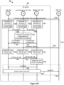
- the base station 114 After defining 316 a CSI process configuration for the UECS 108, the base station 114 transmits 318 a control signal including the CSI process configuration to the UECS 108, as shown in Fig. 3B .
- the base station 114 transmits 318 the control signal to the UECS 108 via a single control channel (e.g., PDCCH) that is specific to the UECS 108.
- the control signal including the CSI process configuration may be an RRC message, or a higher level message such as a MAC message, RLC message, or PDCP message.
- the base station 114 includes the CSI process configuration within downlink control information (DCI) included in the control signal.
- DCI downlink control information
- Each UE of the UECS 108 can receive the same control signal (channel conditions permitting), with the UECS 108 effectively operating as a distributed antenna receiver. If a particular UE is experiencing problems receiving signals from the base station 114 but can still communicate with one or more other UEs in the UECS 108, other UEs of the UECS 108 may receive the control signal, process the control signal in the manner discussed below, and forward the processed control information to that UE using a wireless local connection.
- all of the UEs 102, 104, and 106 receive the control signal transmitted 318 by the base station 114.
- each of the UE 106, the UE 104, and the master UE 102 generates (320, 322, and 324, respectively) respective I/Q samples by demodulating the received control signal.
- the I/Q samples represent the control signal after the RF signal is down-converted and demodulated into in-phase (I) and quadrature (Q) components.
- the UE 104 is acting as the joint-receiver UE that performs joint processing.
- the UE 106 transmits 328 its I/Q samples to the joint-receiver UE 104, and the master UE 102 transmits 326 its I/Q samples to the joint-receiver UE 104, via the local wireless network.
- the joint-receiver UE 104 After the joint-receiver UE 104 receives the I/Q samples from the UEs 102, 106, the joint-receiver UE 104 decodes 330 the CSI process configuration by processing the I/Q samples received from the UEs 102, 106 together with the I/Q samples that the joint-receiver UE 104 itself generated 322. To decode 330 the CSI process configuration, the joint-receiver UE 104 first time aligns and consolidates (e.g., sums) the I/Q samples of UEs 102, 104, and 106.
- consolidates e.g., sums
- the joint-receiver UE 104 By consolidating the I/Q samples, the joint-receiver UE 104 produces a linear power gain and can obtain a stronger signal compared to the signal received by any individual UE, thereby increasing the likelihood that the joint-receiver UE 104 will be able to successfully decode 330 the CSI process configuration (and the DCI as a whole, if the CSI process configuration is included in the DCI).
- the joint-receiver UE 104 then distributes the decoded CSI process configuration by transmitting (332, 334) the CSI process configuration to the other UEs (106, 102) in the UECS 108 via the local wireless network.
- the joint-receiver UE 104 transmits 334 the CSI process configuration to the master UE 102 but not to the UE 106, and the master UE 102 then transmits the CSI process configuration to each UE in the UECS 108 (possibly excluding the joint-receiver UE 104), or to at least one other UE in the UECS 108 that then further distributes the CSI process configuration (e.g., forming part of a transmission chain within the local wireless network).
- Events 320 through 336 are collectively referred to in Fig. 3B as event 337.
- each of the UEs 102, 104, and 106 may self-configure according to the information in the CSI process configuration, in order to prepare to receive the reference signal from the base station 114. That is, when the base station 114 at some later point transmits 336 the reference signal (e.g., CSI-RS) to the UECS 108, the UEs 102, 104, and 106 know the timing and the frequency of that reference signal, and therefore can detect and measure the reference signal.
- the base station 114 transmitting 336 a "reference signal," in the singular. It is understood, however, that the base station 114 may transmit a set of multiple reference signals to the UECS 108 as a whole. For example, the base station 114 may transmit a different reference signal from each antenna (e.g., of multiple antennas 170) of the base station 114.
- Each UE that detects/receives the reference signal determines (338, 340, and 342, respectively) a UE-specific CSI report based on the reference signal.
- the UE-specific CSI report includes a variety of information estimated by the UE based on how well the UE was able to receive the reference signal.
- the UE-specific CSI report may include a CQI, PMI, and/or RI as determined by the individual UE based on its measurements of the reference signal, with the CQI indicating an MCS that the individual UE supports.
- the information in the UE-specific CSI report indicates how many MIMO layers the individual UE can process and/or how many antennas the UE has available for reception.
- the UEs 104 and 106 transmit (344, 346) their respective UE-specific CSI reports to the master UE 102, which processes the UE-specific CSI reports to determine 348 a joint CSI report for the UECS 108.
- the master UE 102 may assign another UE of the UECS 108 (e.g., the joint-receiver UE 104) to perform the processing to determine the joint CSI report. If the master UE 102 assigns the joint-receiver UE 104 to determine the joint CSI report, for example, then the UE 106 and the master UE 102 transmit their respective UE-specific CSI reports to the joint-receiver UE 104.
- the joint CSI report may include the same types of parameters as the individual, UE-specific CSI report, but the values of the parameters reflect the current channel quality and current reception capabilities of the UECS 108 as a whole.
- the joint CSI report is, in some implementations and scenarios, different from the UE-specific CSI report for any individual UE.
- the parameters of the joint CSI report indicate how many streams, or MIMO layers, the base station 114 should use to transmit to the UECS 108.
- One or more parameters in the joint CSI report may depend on joint processing capabilities of the UECS 108 (e.g., as determined 306 by the master UE 102).
- the master UE 102 may determine a joint CQI of the joint CSI report that is lower/worse than if at least one UE were capable of non-linear joint processing. In some implementations, the master UE 102 determines the joint CQI specifically based on the processing capability of the current joint-receiver UE (i.e., in this example, based on whether UE 104 is capable of non-linear joint processing).
- the master UE 102 may choose a particular UE as the joint-receiver UE based at least in part on that UE being capable of non-linear joint processing, particularly if other available UEs of the UECS 108 are only capable of linear joint processing.
- the joint CSI report may also include (e.g., within a CQI of the joint CSI report) a suggested MCS that can be supported by the UECS 108 during joint reception, and/or otherwise indicate a suitable MCS for the UECS 108.
- the suggested MCS generally depends on the joint reception capability information of the UECS 108. That is, in at least some scenarios, the UECS 108 can successfully (jointly) receive signals from the base station 114 that use the suggested MCS, but each individual UE of the UECS 108 is unable to do so.
- the master UE 102 after the master UE 102 (or another UE of the UECS 108, if the master UE 102 has delegated the determination of the joint CSI report) determines 348 the joint CSI report, the master UE 102 alone transmits the joint CSI report to the base station 114.
- the master UE 102 may leverage the joint transmission ability of the UECS 108 to provide the joint CSI report to the base station 114 (e.g., similar to step 315 of Fig. 3A ). In such implementations, the master UE 102 first transmits 350 the joint CSI report to the UEs 104 and 106.
- the master UE 102 may facilitate joint transmission by generating I/Q samples corresponding to the joint CSI report and transmitting these I/Q samples to the UEs 104 and 106.
- the UEs of the UECS 108 i.e., the UEs 102, 104, and 106) then act as a distributed antenna transmitter to jointly transmit 352 the joint CSI report to the base station 114.
- Events 350 and 352 are collectively referred to in Fig. 3B as event 355.
- the sequence of events shown in Fig. 3B is repeated whenever the base station 114 defines a new CSI process configuration for the UECS 108.
- the sequence of events may be repeated because the base station 114 has received a new indication of joint reception capability information from the UECS 108 (e.g., similar to event 310) perhaps reflective of a new UECS composition of UEs, or possibly because the base station has received a joint CSI report from the UECS 108 that requires an updated channel configuration (e.g., similar to event 352).
- Fig. 4 is a messaging diagram of a more specific example scenario in which one UE of the UECS 108 (UE 106) reports a poor CQI to the master UE 102.
- the UECS 108 includes the master UE 102, the joint-receiver UE 104, and the UE 106.
- the joint-receiver UE 104 is shown as a separate UE, the master UE 102 in other scenarios also performs the functions of the joint-receiver and thus UE 104 is not present or behaves similar to non-master, non-joint-receiver UE 106.
- the scenario 400 begins when, similar to 302, the UE 104 transmits 402 its UE-specific reception capability information to the master UE 102.
- the UE 104 has two transmit-receive antennas and RF front ends (e.g., as in Fig. 2 ), and its UE-specific reception capability information therefore indicates that the UE 104 can support 2-layer (2x2) MIMO.
- the UE 106 also transmits 404 its UE-specific reception capability information to the master UE 102.
- the UE 106 also has two transmit-receive antennas (e.g., as in Fig. 2 ), and its UE-specific reception capability information likewise indicates that the UE 106 can support 2-layer MIMO.
- the master UE 102 analyzes the UE-specific reception capability information received from the UEs 104 and 106 to determine 406 joint reception capability information for the UECS 108. Combining the capabilities of the UE 104 and the UE 106 with its own 2-layer reception capability, the master UE 102 determines 406 joint reception capability information indicating a 6-layer (6x6) MIMO capability.
- the UECS 108 then distributes the 6x6 joint reception capability information amongst the group, and jointly transmits an indication of the 6x6 joint reception capability information to the base station 114.
- Event 415 may be similar to event 315 of Fig. 3A , for example.
- the base station 114 then defines 416 a CSI process configuration for the UECS 108 based on the 6x6 joint reception capability reported by the UECS 108, and transmits 418 the CSI process configuration to the UECS 108.
- the UEs of the UECS 108 jointly receive the CSI process configuration, prepare to receive a reference signal using the CSI process configuration, and receive the reference signal according to the CSI process configuration.
- Event 437 may be similar to event 337 of Fig. 3A , for example.
- the UEs 106, 104, and 102 use (e.g., measure) the reference signal to determine (438, 440, and 442, respectively) their respective UE-specific CSI reports.
- the UE 106 is experiencing poor channel conditions (e.g., due to fading, multipath, distance from the base station 114, etc.), and therefore determines 438 a CSI report that includes a poor CQI.
- the UE 106 may measure a weak/noisy reference signal on either of its two antennas (e.g., because of a low signal-to-noise ratio (SNR) or signal-to-interference-plus-noise ratio (SINR)).
- SNR signal-to-noise ratio
- SINR signal-to-interference-plus-noise ratio
- the UE 104 is not experiencing poor channel conditions, and therefore determines 440 a CSI report that includes a better CQI.
- the UEs 104 and 106 transmit (444, 446) their respective UE-specific CSI reports to the master UE 102, and the master UE 102 processes the received UE-specific CSI reports, and its own CSI report, to determine 448 a joint CSI report for the UECS 108. Because the CSI report for the UE 106 indicates a poor CQI, the joint CSI report indicates that the UECS 108 only has a 4-layer (4x4) MIMO reception capability, even though (under better conditions) the UECS 108 theoretically has a 6-layer MIMO reception capability, as was indicated by the joint reception capability information determined 406 earlier by the master UE 102.
- the master UE 102 distributes the joint CSI report to the UECS 108, and the UECS 108 jointly transmits the joint CSI report indicating a 4-layer MIMO reception capability to the base station 114.
- the event 455 may be similar to the event 355 of Fig. 3B , for example.
- the base station 114 then may adjust 456 any future transmissions and/or resource allocation for the UECS 106 to reflect the 4-layer MIMO reception capability of the UECS 108.
- the base station 114 may define a new CSI process configuration based on the received joint CSI report and transmit the new CSI process configuration to the UECS 108, similar to events 316 and 318, respectively, of Fig. 3A and 3B .
- the base station 114 may transmit 458 a signal (which could be either a control signal or a data signal) to the UECS 108 in accordance with the current 4-layer MIMO reception capability of the UECS 108.
- the UE 106 because of its poor CQI, does not effectively participate in the joint reception. Instead, the UEs 104 and 102 jointly receive the 4x4 MIMO transmission, by operating as a distributed antenna receiver with a lower number of antenna elements. Thus, only the UEs 104 and 102 generate (462, 464) I/Q samples by demodulating the signal.
- the UE 104 If the UE 104 is acting as the joint-receiver UE 104, as is the case in scenario 400, then the UE 102 transmits 466 its I/Q samples to the joint-receiver UE 104.
- the joint-receiver UE 104 then may decode the signal content (control information or data, depending on the signal type) by processing the I/Q samples, similar to event 330 of Fig. 3A .
- the joint-receiver UE 104 then can transmit (470, 472) the control information or data to both the UE 106 and the UE 102.
- Fig. 5 is a flow diagram of an example method 500 for transmitting an indication of joint channel state to a base station (e.g., the base station 114), which can be implemented in a UE of Fig. 1 .
- the UE that performs the method 500 may be acting as a master UE of a UECS (e.g., the master UE 102 of the UECS 108 in Figs. 3A-4 ). In some implementations, the UE may also be acting as the joint-receiver UE.
- the method 500 begins at block 502, where the UE receives a reference signal from the base station (e.g., event 336 of Fig. 3B ).
- the UE determines a first indication of UE-specific channel state at block 504 (e.g., event 342 of Fig. 3B or event 442 of Fig. 4 ).
- the UE receives a second indication of UE-specific channel state from a second UE (e.g., event 344 or 346 of Fig. 3B , or events 444 or 446 of Fig. 4 ).
- the UE determines an indication of joint channel state based on the first indication of UE-specific channel state and the second indication of UE-specific channel state (e.g., event 348 of Fig. 3B or event 448 of Fig. 4 ).
- the UE transmits the indication of joint channel state to the base station.
- the UE may transmit the indication of joint channel state (e.g., a joint CSI report) to the base station by itself, or may distribute the indication of joint channel state to the other UEs of the UECS, which jointly transmit the indication of joint channel state to the base station (e.g., event 355 of Fig. 3B or event 455 of Fig. 4 ).
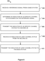
- Fig. 6 is flow diagram of an example method 600 for transmitting an indication of joint channel state to a base station (e.g., the base station 114), which can be implemented in a UE of Fig. 1 .
- the UE that performs the method 600 may be acting as a joint-receiver UE of the UECS 108 (e.g., the joint-receiver UE 104 of Fig. 3A and 3B ) or as another UE of the UECS 108 that is not the joint-receiver UE or the master UE (e.g., the UE 106 of Fig. 3A and 3B ).
- the method 600 begins at block 602, where the UE receives a reference signal from the base station (e.g., event 336 of Fig. 3B ). Based on the reference signal, the UE determines an indication of UE-specific channel state based on the reference signal at block 604 (e.g., event 340 of Fig. 3B or event 440 of Fig. 4B). In some implementations, blocks 602 and 604 include receiving and processing, respectively, a set of multiple reference signals (e.g., one per base station antenna, etc.). Next, at block 606, the UE transmits the indication of UE-specific channel state to a second UE (e.g., event 344 of Fig. 3B or event 444 of Fig. 4 ).
- a second UE e.g., event 344 of Fig. 3B or event 444 of Fig. 4 .
- the UE receives an indication of joint channel state from the second UE (e.g., event 350 of Fig. 3B ).
- the UE transmits the indication of joint channel state to the base station (e.g., event 352 of Fig. 3B ).
- Fig. 7 is a flow diagram of an example method 700 for transmitting a CSI process configuration to a UECS (e.g., the UECS 108) and receiving an indication of joint channel state from the UECS, which can be implemented in a base station (e.g., the base station 114 of Fig. 1 ).
- the method 700 begins at block 702, where the base station determines a CSI process configuration for the UECS (e.g., event 316 of Fig. 3A or event 416 of Fig. 4 ).
- the base station transmits a control signal including the CSI process configuration to the UECS (e.g., event 318 of Fig. 3B or event 418 of Fig. 4 ).
- the base station transmits a reference signal to the UECS in accordance with the CSI process configuration (e.g., event 336 of Fig. 3B or event 437 of Fig. 4 ).
- block 706 includes transmitting a set of multiple reference signals (e.g., one per base station antenna, etc.).
- the base station receives an indication of joint channel state of the UECS from at least one UE of the UE group (e.g., event 354 of Fig. 3B or event 455 of Fig. 4 ).
- a user device in which the techniques of this disclosure can be implemented can be any suitable device capable of wireless communications such as a smartphone, a tablet computer, a laptop computer, a mobile gaming console, a point-of-sale (POS) terminal, a health monitoring device, a drone, a camera, a media-streaming dongle or another personal media device, a wearable device such as a smartwatch, a wireless hotspot, a femtocell, or a broadband router.
- the user device in some cases may be embedded in an electronic system such as the head unit of a vehicle or an advanced driver assistance system (ADAS).
- ADAS advanced driver assistance system
- the user device can operate as an internet-of-things (IoT) device or a mobile-internet device (MID).
- IoT internet-of-things
- MID mobile-internet device
- the user device can include one or more general-purpose processors, a computer-readable memory, a user interface, one or more network interfaces, one or more sensors, etc.
- Modules may can be software modules (e.g., code, or machine-readable instructions stored on non-transitory machine-readable medium) or hardware modules.
- a hardware module is a tangible unit capable of performing certain operations and may be configured or arranged in a certain manner.
- a hardware module can comprise dedicated circuitry or logic that is permanently configured (e.g., as a special-purpose processor, such as a field programmable gate array (FPGA) or an application-specific integrated circuit (ASIC), a digital signal processor (DSP), etc.) to perform certain operations.
- FPGA field programmable gate array
- ASIC application-specific integrated circuit
- DSP digital signal processor
- a hardware module may also comprise programmable logic or circuitry (e.g., as encompassed within a general-purpose processor or other programmable processor) that is temporarily configured by software to perform certain operations.
- programmable logic or circuitry e.g., as encompassed within a general-purpose processor or other programmable processor
- the decision to implement a hardware module in dedicated and permanently configured circuitry, or in temporarily configured circuitry (e.g., configured by software) may be driven by cost and time considerations.
- the techniques can be provided as part of the operating system, a library used by multiple applications, a particular software application, etc.
- the software can be executed by one or more general-purpose processors or one or more special-purpose processors.
Landscapes
- Engineering & Computer Science (AREA)
- Signal Processing (AREA)
- Computer Networks & Wireless Communication (AREA)
- Quality & Reliability (AREA)
- Mobile Radio Communication Systems (AREA)
Description
- This disclosure relates generally to wireless communications and, more particularly, to grouping strategies for coordinating user devices in wireless communication systems.
- In wireless communication systems, such as fifth-generation (5G) radio access ("NR") networks, a base station (e.g., a gNB) must configure downlink and uplink transmissions to and from user devices within the base station's coverage area. To perform this configuration, the base station transmits control information indicating random access channel information, scheduling grants, power control commands, coding information, etc. via a control channel. However, handling the configuration of a large number of user devices can require extensive control channel overhead (e.g., time and frequency resources), leading to a reduction in network efficiency.
- Further, the signal strength at the location of a particular user device (commonly referred to as a user equipment ("UE")) and/or the reception capability of a particular UE may be poor. For example, the UE may be located at a cell edge or experiencing fading effects due to Doppler shift, multipath propagation, or shadowing. The base station may struggle to establish communication with the UE, further diminishing overall network efficiency.
- To address some of these issues, various schemes for coordination (or "grouping") among different UEs have been proposed. Despite these various schemes, there are further opportunities to capture more of the network efficiency improvements that UE groupings can offer, and to flexibly scale coordination schemes to better leverage larger UE group sizes.
-
WO 2016/120686 A1 relates to coordinating device-to-device communications amongst a plurality of devices. The document states that the helper UE device may be able to send a single CQI value and/or single CSI value for the collective channel. Specifically, one or more of the UE devices may determine a CQI or CSI value defined based on the plurality of channels (between each device and the RRH) and their qualities when the devices are helping each other. - According to techniques of this disclosure, a number of UEs form a group (referred to herein as a "UE Coordination Set" or "UECS") that a base station views-at least in some respects and at some protocol stack layers-as a single UE or "virtual" UE. While in previously proposed UE grouping schemes, the base station of the serving cell is unaware of changing joint reception capabilities of the UE group (or UECS, as the UE group is referred to herein) over time (e.g., as particular UEs experience poor channel conditions), the techniques of this disclosure provide feedback to the base station that the base station can use to quickly adapt downlink transmissions to suit current capabilities of the UECS.
- In particular, a coordinating or "master" UE of the UECS collects individual reception capability information from each UE in the UECS. The capability information may indicate how many multiple-input, multiple-output (MIMO) layers the UE can process, and possibly other information (e.g., whether the UE can perform non-linear processing on a received MIMO signal). For example, a UE with two antennas may report a 2-layer, 2x2 MIMO processing capability. The master UE analyzes the individual UE capabilities to determine a joint capability for the UECS, which the master UE reports to the base station. For instance, if the UECS consists of two UEs that each support 2-layer MIMO processing under the current channel conditions, the master UE may report a 4-layer MIMO processing capability for the UECS. As another example, the same two UEs may only be able to support single-input, single-output (SISO) processing under their current channel conditions, and the master consequently reports a 2-layer MIMO processing capability for the UECS. The master UE then distributes the joint capability information to the other UEs in the UECS to enable joint transmission from the UECS to the base station.
- Based on the received joint capability information of the UECS, the base station defines/determines a channel state information (CSI) process configuration that is specific to the UECS. The CSI process configuration includes, for example, timing and frequency information for a reference signal (e.g., for a CSI-RS) that the base station will send to the UECS. The CSI process configuration may also include other information needed for the CSI process, such as code domain information (e.g., for signal pre-coding). The base station transmits a control signal (e.g., a radio resource control (RRC) message, or a lower layer message) including the CSI process configuration to the UECS. The UECS jointly receives the control signal, and the UEs process the CSI process configuration in order to, for example, identify the time and frequency resources on which the UEs are to receive the reference signal. In some implementations and/or scenarios, the base station defines resources for, and transmits, multiple reference signals (e.g., one per base station antenna).
- At a later time, the base station transmits the reference signal to the UECS, and each of the UEs performs measurements on the received reference signal to determine UE-specific channel quality and generate a UE-specific CSI report. Each UE-specific CSI report may include parameters such as a channel quality indicator (CQI), a precoding matrix indicator (PMI), a rank indicator (RI), and/or a modulation and coding scheme (MCS) index. The UEs in the UECS forward their respective individual CSI reports to the master UE, which then calculates a joint CSI report for the UECS as a whole. The joint CSI report may include the same types of parameters as the individual CSI reports, for example. In some implementations, the parameters include parameters that indicate how many streams, or MIMO layers, the base station should use. Moreover, one or more parameters in the joint CSI report may depend on certain joint processing capabilities of the UECS. For example, if the UECS only includes UEs that are capable of linear joint processing, then the master UE may report a lower/worse joint CQI (in the joint CSI report) than would be the case if at least one UE were capable of non-linear joint processing.
- The invention is defined by the subject-matter of the independent claims. Particular embodiments of the invention are set out in the dependent claims.
-
-
Fig. 1 illustrates an example communication system in which joint channel state feedback techniques for a User Equipment Coordination Set (UECS) of this disclosure can be implemented; -
Fig. 2 illustrates an example antenna arrangement supporting multiple-input, multiple-output (MIMO) communications between UEs and a base station; -
Figs. 3A and3B are a messaging diagram of an example scenario in which the UEs of a UECS transmit joint reception capability and state information of the UECS to a base station; -
Fig. 4 is a messaging diagram of a more specific example scenario in which one UE of the UECS reports a poor channel quality indicator (CQI) to the master UE; -
Fig. 5 is a flow diagram of an example method for providing a base station with an indication of joint channel state, which can be implemented in a UE ofFig. 1 that is acting as a master UE; -
Fig. 6 is flow diagram of another example method for providing a base station with an indication of joint channel state, which can be implemented in a UE ofFig. 1 that is not acting as a master UE; -
Fig. 7 is a flow diagram of an example method for obtaining joint channel state feedback from a UECS, which can be implemented in the base station ofFig. 1 . - The embodiments related to
figures 3A ,3B ,5 ,6 , and7 are comprised within the scope of the claims. -
Fig. 1 illustrates anexample communication system 100 in which joint channel state feedback techniques for a User Equipment Coordination Set (UECS) of this disclosure can be implemented. Thecommunication system 100 includes a number of user equipment (UE), including UE 102, UE 104, and UE 106. Each ofUEs group 108, also referred to herein as a UECS 108. WhileFig. 1 depicts three UEs, the UECS 108 may include any number (greater than one) of UEs. The UECS 108 can locally coordinate uplink (UL) transmission and downlink (DL) reception to and from abase station 114, using techniques described in further detail below. - The
base station 114 is communicatively connected to a core network (CN) 110 via an NG interface, for example. In some implementations, thebase station 114 is a 5G New Radio (NR) base station operating as a g Node B (gNB), and theCN 110 is a 5G core network (5GC). In other implementations, however, thecommunication system 100 can include one or more base stations that operate according to radio access technologies (RATs) of types other than NR, and these base stations can be connected to CNs of other types. The CN 110 can be, for example, a 5G core network (5GC), a less advanced core network (e.g., an evolved packet core (EPC)), or, conversely, a more advanced core network. - The
base station 114 is associated with a RAN 112 and provides coverage to acell 116. WhileFig. 1 depicts thebase station 114 as associated with only onecell 116, it is understood that thebase station 114 may also cover one or more additional cells not shown inFig. 1 . Further, the RAN 112 can include any suitable number of base stations that collectively support one or more RATs. Each UE, such as the UE 102, can communicatively connect with the RAN 112 via thebase station 114 when operating within thecell 116, and in turn can communicatively connect with theCN 110 via the RAN 112. - The UE 102 is equipped with at least
processing hardware 130, a UE group management unit 136, at least oneantenna 140, and a localwireless network interface 150. WhileFig. 1 depicts only theUE 102 as including theprocessing hardware 130, the UE group management unit 136, theantenna 140, and thelocal wireless network 150, it is understood that each of theUEs processing hardware 130 can include one or more general-purpose processors (e.g., CPUs) and at least one non-transitory computer-readable memory storing instructions executable on the one or more general processors and/or special-purpose processing units, such as a wireless communication chipset. - The
processing hardware 130 includes a physical (PHY)layer controller 132. ThePHY layer controller 132 is responsible for internal procedures at aPHY layer 182 of a wirelesscommunication protocol stack 180, such as demodulating and decoding downlink control and data signals received from a base station (e.g., the base station 114), encoding and modulating uplink control and data signals, and so on. Additionally, thePHY layer controller 132 includes a channel state information (CSI)controller 133. As referred to herein, the CSI may conform to the CSI defined by current standards (e.g., 3GPP Technical Specifications 36.312 and/or 38.312), or may correspond to channel state information more generally. TheCSI controller 133 supports functions related to determining reception capability information, joint reception capability information, CSI reports, and/or joint CSI reports, as described below with reference toFigs. 3A-4 . - The
processing hardware 130 also includes an upper layer controller 134. The upper layer controller 134 is responsible for internal procedures at a correspondingupper layer 184 above thePHY layer 182 of theprotocol stack 180, such as aggregating uplink data and disaggregating downlink data for theUECS 108. Theupper layer 184 may be, for example, a medium access control (MAC) layer, a packet data convergence protocol (PDCP) layer, or a radio link control (RLC) layer. For example, the upper layer controller 134 may support channel access, addressing, quality of service (QoS) and other functions of a MAC layer, user plane data transfer, control plane data transfer, integrity protection and other functions of a PDCP layer, or segmentation and other functions of an RLC layer. While not shown inFig. 1 , theprocessing hardware 130 may also include a controller for each of a number of other layers, such as a Radio Resource Control (RRC) controller and a mobility management (MM) controller associated with RRC and MM layers of theprotocol stack 180, respectively. - The UE group management unit 136 of the
UE 102 is generally responsible for functions related to UE grouping functions, such as sharing signals with the other UEs of the UECS 108 (e.g., theUEs 104 and 106) as discussed further below. The UEs of theUECS 108 may communicate with each other over at least one local wireless network, which is not depicted inFig. 1 . The local wireless network may correspond to a personal area network (PAN), near-field communication (NFC), Bluetooth™, wireless local area network (WLAN), or any other suitable communication standard(s) or protocol(s). The localwireless network interface 150 of theUE 102 generally facilitates communications with the other UEs of theUECS 108 on the local wireless network. The UE group management unit 136 may be jointly implemented by theprocessing hardware 130 and the localwireless network interface 150, or may be implemented by another controller of theUE 102 that is not shown inFig. 1 . - The
base station 114 includes at least oneantenna 170 to communicate with the other elements of thecommunication system 100. Thebase station 114 also includesprocessing hardware 160, which can include one or more general-purpose processors (e.g., CPUs) and at least one non-transitory computer-readable memory storing instructions executable on the one or more general processors and/or special-purpose processing units, such as a wireless communication chipset. Similar to theprocessing hardware 130 of theUE 102, theprocessing hardware 160 can include aPHY layer controller 162 and an upper layer controller 164 corresponding to thePHY layer 182 andupper layer 184, respectively, of theprotocol stack 180.Controllers 162 and 164 may perform similar or corresponding functions ascontrollers 132 and 134, but from the perspective of thebase station 114 rather than theUE 102. For example, thePHY layer controller 162 may encode and modulate downlink control and data signals transmitted to theUECS 108, and the upper layer controller 164 may aggregate downlink data for theUECS 108 and disaggregate uplink data received from theUECS 108.. - In addition, the
PHY layer controller 162 includes a CSI process controller 163. The CSI process controller 163 may perform similar functions as theCSI controller 133, but from the perspective of thebase station 114 rather than theUE 102. For example, the CSI process controller 163 defines CSI process configurations that thebase station 114 will transmit to theUECS 108, as described below with reference toFigs. 3B and4 . - The upper layer controllers 134 and 164,
PHY layer controllers CSI controller 133 and CSI process controller 163, and UE group management unit 136 can each be implemented using any suitable combination of hardware, software, and/or firmware. In one example implementation, thecontrollers respective processing hardware - As noted above, the
UE 102 includes at least oneantenna 140, for receiving signals transmitted to theUE 102 and transmitting signals from theUE 102. TheUE 102 may be equipped withmultiple antennas 140 to support multiple-input, multiple-output (MIMO) communications, or with only asingle antenna 140. For example, theUE 102 may have two transmit-receive antennas to support two simultaneous transmission/reception paths, or may have separate transmit and receive antennas, etc. MIMO communication between thebase station 114 and theUEs Fig. 2 . Moreover, as discussed further below, the base station 114 (e.g., the PHY controller 162) may determine an antenna port at thePHY layer 182 for eachphysical antenna 140 of theUE 102. - Initially, as noted above, the
UEs Fig. 1 , form theUECS 108. TheUECS 108 may be formed in a variety of ways, depending on the implementation and/or scenario. In some implementations, for example, UEs can locally coordinate with each other, with little or no input from thebase station 114, to form theUECS 108. TheUEs UEs UEs UEs - In other implementations, the
base station 114 directs or partially directs formation of theUECS 108. Thebase station 114, for example, detects theUEs cell 116, and assigns each UE to theUECS 108. Thebase station 114 may also request that theUEs UECS 108, and only assign a particular UE to theUECS 108 if that UE responds with an acknowledgement and/or approval of the request. Thebase station 114 may select UEs for theUECS 108 based on the location of each UE relative to thebase station 114 and to the other UEs, and/or other factors. Thebase station 114 may also select certain UEs for theUECS 108 depending on beam scheduling, for example, with thebase station 114 only selecting UEs that are in the same beam. Thebase station 114 may also select which single UE is to function as the master UE of theUECS 108. - Grouping of UEs into the
UECS 108 can provide various advantages. In some implementations, for example, theUECS 108 can jointly receive downlink control and data signals from thebase station 114, and jointly transmit uplink control and data signals to thebase station 114. Because each UE of theUECS 108 is equipped with at least one antenna (e.g., theantenna 140 of the UE 102), theUECS 108 can utilize the antennas of the individual UEs as a distributed antenna arrangement for both reception and transmission. Accordingly, theUECS 108 can have reception and transmission capabilities that exceed those of theindividual UEs UECS 108 experiences poor reception, that UE may rely on the other UEs of theUECS 108 to receive information from thebase station 114 and forward that information to the UE with poor reception. Further, theUECS 108 can leverage the combined processing power of theUEs UECS 108 as a whole. - The master UE may function as a "joint-receiver" UE to perform the functions necessary to facilitate joint reception, or the master UE may delegate that responsibility by assigning another UE to be the joint-receiver UE. In some implementations, the
base station 114 directs the master UE to select a joint-receiver UE, or directly assigns the joint-receiver UE. In other implementations, the master UE selects a joint-receiver UE with little or no input from the base station. The master UE may change which UE acts as the joint-receiver UE depending on changing power and reception conditions and/or capabilities of the UEs in theUECS 108. Regardless of how the joint-receiver UE is selected, or re-assigned, the joint-receiver UE may facilitate joint reception using any of the various techniques described below with respect toFigs. 3B-4 . - In some implementations of the
communication system 100, theUECS 108 andbase station 114 take advantage of the distributed antenna arrangement of the UEs by implementing multiple-input, multiple-output (MIMO) communications for the uplink and/or downlink. MIMO communications can improve data rates (with spatial multiplexing, i.e., transmitting different data from different antennas) or error rates (with spatial diversity, i.e., transmitting redundant data on different antennas), for both the uplink and downlink. - In the
example antenna arrangement 200 ofFig. 2 , thebase station 114 includes four transmit-receiveantennas UE 102 includes two transmit-receiveantennas 210 and 212 each having its own transmit/receive circuitry in the RF front end, and theUE 104 also includes two transmit-receiveantennas UEs base station 114, using its four transmit-receive antennas, can support four MIMO layers. While a single one of theUEs base station 114, theUEs UECS 108, are capable of 4x4 communication with thebase station 114. It is understood that theUEs base station 114, may instead have more or fewer antennas than are depicted inFig. 2 , thereby supporting more or fewer MIMO layers. - To configure MIMO communications with the
UECS 108, thebase station 114 first determines the total number of antennas the UECS 108 (i.e., theUEs 102 and 104) has available, and the signal quality of the different streams between theUECS 108 and thebase station 114. It is understood that references made herein to the number of different antennas of a UE or base station may mean the number of physical antennas, or may mean the number of antennas or antenna sets that are coupled to different RF front ends. Thus, for example, a combination of a patch antenna and a monopole antenna at a UE or base station may "count" as only one antenna if both antennas are coupled to the same RF front end (e.g., for purposes of generating a particular antenna radiation pattern). - Generally speaking, for the downlink, the
base station 114 determines how to configure MIMO communications with a UE (e.g., the UE 102) based on CSI received from theUE 102. Thebase station 114 similarly defines a CSI process configuration that indicates time and frequency resources that thebase station 114 will use to transmit a reference signal (e.g., a CSI-RS) to theUECS 108. In some implementations, theUE 102 can use (e.g., perform measurements on) the reference signal to estimate various parameters relating to channel quality and to estimate suitable MIMO or SISO configurations for the downlink, and transmits this information to thebase station 114 in a CSI report. - Parameters included in the CSI report indicate how well the UE 102 (and more specifically, the antennas of UE 102) is currently able to receive from the base station 114 (i.e., as a result of the channel conditions currently experienced at the antennas of the UE 102). For instance, the CSI report can include indications of how many streams, or MIMO layers, the
UE 102 can currently process, thereby indicating a number of antennas of theUE 102 that are available for reception. Examples of the parameters that theUE 102 can include in the CSI report include a channel quality indicator (CQI), a rank indicator (RI), and a precoding matrix indicator (PMI). The CQI may indicate a modulation and coding scheme (MCS) (e.g., by including an MCS index). - The RI, for instance, specifies a suggested number of MIMO layers the
base station 114 should use when transmitting to theUE 102, and is based on the number of antennas theUE 102 has available to receive MIMO streams. The PMI may suggest a suitable MIMO precoding matrix for the specified RI, and the CQI may specify a modulation and coding scheme (MCS) suitable for the specified PMI. Further, the CSI report can also include a CSI-RS resource indicator (CRI) to identify a beam the CSI report is based on (for example, if thebase station 114 transmits reference signals on multiple beams). In implementations where thebase station 114 is a gNB, theUE 102 also can include in the CSI report a layer indicator (LI) to notify thebase station 114 which MIMO layer theUE 102 has identified as the best one, as well as a Synchronization Signal Block (SSB) Physical Broadcast Channel (PBCH) Block Resource Indicator (SSBRI) and layer 1 reference signal received power (L1-RSRP), which thebase station 114 can use in beam management and mobility procedures. - If the
UEs Fig. 2 have not formed a UE group (e.g., the UECS 108), then thebase station 114 transmits a reference signal to each of theUEs base station 114 for each of theUEs 102 and 104 (i.e., with different time/frequency resources for the two reference signals). Each of theUEs base station 114. However, if theUEs UECS 108, thebase station 114 can define a single CSI process configuration for theUECS 108 as a whole, and transmit a reference signal in accordance with the CSI process configuration defined for the group. TheUECS 108 can jointly receive and process the control signal including the CSI process configuration, and each UE can receive and process (e.g., perform measurements on) the reference signal. Based on CSI reports generated by the individual UEs of theUECS 108, theUECS 108 determines a joint CSI report, which may (depending on current channel conditions for each UE) reflect a greater reception capability than is possible for any individual UE. - Using the techniques discussed below with reference to
Figs. 3A-7 , the UEs of theUECS 108 can determine a joint CSI report based on the joint reception capability of the group, and transmit the joint CSI report together to thebase station 114. WhileFigs. 3A-7 and the accompanying descriptions refer specifically to theUEs UECS 108, and thebase station 114 ofFig. 1 , it is understood that the following techniques may be implemented by other components and/or in systems other than thecommunication system 100 ofFig. 1 . -
Figs. 3A and3B together illustrate a messaging diagram of afirst example scenario 300 in which the UEs of theUECS 108 transmit joint reception capability and state information of theUECS 108 to thebase station 114. In theexample scenario 300, theUE 102 is acting as the master UE of theUECS 108, theUE 104 is acting as the joint-receiver UE 104 of theUECS 108, and theUE 106 is another UE in theUECS 108 that is neither the master nor the joint-receiver. It is understood that, in some scenarios and/or implementations, theUEs UECS 108. Moreover, in some scenarios and/or implementations, themaster UE 102 does not assign a joint-receiver UE, and instead performs the joint-reception functions. - The
example scenario 300 begins when a UE in aUECS 108, such as the joint-receiver UE 104, transmits 302 its own UE-specific reception capability information to themaster UE 102 via a local wireless network (e.g., the local wireless network discussed above in connection withFig. 1 ). For each UE, the UE-specific reception capability information may indicate, for example, how many MIMO layers the UE can process, or can currently process under current channel conditions. For example, a UE with two antennas can report a 2-layer, 2x2 MIMO processing capability. In some cases, UE-specific reception capability information indicates that the corresponding UE only supports SISO processing. In some implementations, the UE-specific reception capability information also indicates whether the UE can perform linear or non-linear processing on a received MIMO (or SISO) signal. More generally, the UE-specific reception capability information may indicate a number of antennas of the UE, or include an indication of a number of antenna ports thebase station 114 can determine for the UE. Further, the UE-specific reception capability information reported by each UE may be specific to each of one or more carrier frequency bands. For instance, a UE may report a first number of MIMO layers available for processing signals carried on a first band (e.g., low band), and a second, different number of MIMO layers available for processing signals carried on a different, second band (e.g., mid band). - Another UE, such as
UE 106, may also transmit 304 its UE-specific reception capability information to themaster UE 102 via the local wireless network. WhileFig. 3A depicts theUE 106 as transmitting 304 its UE-specific reception capability information after the joint-receiver UE 104, the relative timing of the transmissions differ from what is shown. For example, theUE 106 may transmit 304 its information prior to, or at the same time that, the joint-receiver UE 104 transmits 302 its information. In addition, while inscenario 300 theUEs master UE 102, themaster UE 102 may instead receive the UE-specific reception capability information from theUEs UE 106 may first transmit its UE-specific reception capability information to the joint-receiver UE 104 or another UE of theUECS 108, and the joint-receiver UE 104 or other UE may forward the information corresponding to theUE 106 to the master UE 102 (e.g., that information alone, or grouped with the UE-specific reception capability information of the forwarding UE). Such scenarios can occur, for example, if theUE 106 has a poor wireless local connection with themaster UE 102 but can communicate better with the joint-receiver UE 104 or another UE of theUECS 108 perhaps using a different wireless local communication technology such as Bluetooth™. The UE-specific reception capability information of a particular UE may be transmitted through several UEs of theUECS 108 before it reaches themaster UE 102, depending on channel conditions and the capabilities of the respective UEs. - By analyzing the UE-specific reception capability information received from the other UEs of the
UECS 108, as well as its own UE-specific reception capability, themaster UE 102 determines 306 joint reception capability information corresponding to the reception capability of theUECS 108 as a whole (i.e., when jointly receiving signals from the BS 114). At least in some scenarios, the joint reception capability of theUECS 108 is different from the reception capability of any individual UE in theUECS 108. For example, the number of MIMO layers that theUECS 108 can process may scale with the number of UEs (and possibly UE antennas) in theUECS 108. If the information received from the joint-receiver UE 104 and theUE 106 atevents UEs master UE 102 itself supports 2-layer processing, then themaster UE 102 determines that theUECS 108 supports 6-layer MIMO processing. - Additionally, in some implementations, the
master UE 102 can delegate the task of determining 306 the joint reception capability information to the joint-receiver UE 104 or another designated UE of theUECS 108. In such implementations, themaster UE 102 collects the individual UE-specific reception capability information and forwards the grouped information to the joint-receiver UE 104 or other designated UE, or informs the other UEs of theUECS 108 to transmit their UE-specific reception capability information directly to the joint-receiver UE 104 or other designated UE. - In some implementations (not shown in
Fig. 3A ), after determining 306 the joint reception capability information, themaster UE 102, alone, transmits an indication of the joint reception capability information to thebase station 114. Alternatively, as depicted inFig. 3A , themaster UE 102 may leverage the joint transmission ability of theUECS 108 to provide the joint reception capability information to thebase station 114. In such implementations, themaster UE 102 transmits 308 an indication of the joint reception capability information to theUEs master UE 102 can choose a joint transmission scheme and coordinate joint transmission from the group in any suitable manner. For example, themaster UE 102 can generate I/Q samples corresponding to the indication of joint channel state and transmit these I/Q samples to theUEs UEs base station 114. For thejoint transmission 310, the UEs use their respective antennas to transmit the indication of joint reception capability information to thebase station 114 in a time-aligned, signal-aligned manner.Events Fig. 3A asevent 315. - The
base station 114 then defines 316 a CSI process configuration for theUECS 108 based on the received joint reception capability information, such that the CSI process configuration is a joint CSI process configuration for theUECS 108 as a whole. To define the CSI process configuration, thebase station 114 allocates resource elements for a reference signal (e.g., for a CSI-RS) that thebase station 114 will transmit to theUECS 108 at a later time. More specifically, the CSI process configuration includes time and frequency domain information that theUECS 108 can use to prepare to receive the reference signal. The CSI process configuration may also include other information, such as an indication of what information thebase station 114 would like to receive from theUECS 108 when theUECS 108 provides a joint CSI report in response to the reference signal. For example, the CSI process configuration may include an indication ofPHY layer 182 parameters thebase station 114 seeks from theUECS 108. - After defining 316 a CSI process configuration for the
UECS 108, thebase station 114 transmits 318 a control signal including the CSI process configuration to theUECS 108, as shown inFig. 3B . In some implementations, thebase station 114 transmits 318 the control signal to theUECS 108 via a single control channel (e.g., PDCCH) that is specific to theUECS 108. The control signal including the CSI process configuration may be an RRC message, or a higher level message such as a MAC message, RLC message, or PDCP message. In some implementations and scenarios, thebase station 114 includes the CSI process configuration within downlink control information (DCI) included in the control signal. - Each UE of the
UECS 108 can receive the same control signal (channel conditions permitting), with theUECS 108 effectively operating as a distributed antenna receiver. If a particular UE is experiencing problems receiving signals from thebase station 114 but can still communicate with one or more other UEs in theUECS 108, other UEs of theUECS 108 may receive the control signal, process the control signal in the manner discussed below, and forward the processed control information to that UE using a wireless local connection. - In the
example scenario 300, all of theUEs base station 114. Thus, each of theUE 106, theUE 104, and themaster UE 102 generates (320, 322, and 324, respectively) respective I/Q samples by demodulating the received control signal. The I/Q samples represent the control signal after the RF signal is down-converted and demodulated into in-phase (I) and quadrature (Q) components. In theexample scenario 300, theUE 104 is acting as the joint-receiver UE that performs joint processing. Thus, theUE 106 transmits 328 its I/Q samples to the joint-receiver UE 104, and themaster UE 102 transmits 326 its I/Q samples to the joint-receiver UE 104, via the local wireless network. - After the joint-
receiver UE 104 receives the I/Q samples from theUEs receiver UE 104 decodes 330 the CSI process configuration by processing the I/Q samples received from theUEs receiver UE 104 itself generated 322. To decode 330 the CSI process configuration, the joint-receiver UE 104 first time aligns and consolidates (e.g., sums) the I/Q samples ofUEs receiver UE 104 produces a linear power gain and can obtain a stronger signal compared to the signal received by any individual UE, thereby increasing the likelihood that the joint-receiver UE 104 will be able to successfully decode 330 the CSI process configuration (and the DCI as a whole, if the CSI process configuration is included in the DCI). - In the implementation shown in
Fig. 3B , the joint-receiver UE 104 then distributes the decoded CSI process configuration by transmitting (332, 334) the CSI process configuration to the other UEs (106, 102) in theUECS 108 via the local wireless network. In other implementations and/or scenarios, the joint-receiver UE 104 transmits 334 the CSI process configuration to themaster UE 102 but not to theUE 106, and themaster UE 102 then transmits the CSI process configuration to each UE in the UECS 108 (possibly excluding the joint-receiver UE 104), or to at least one other UE in theUECS 108 that then further distributes the CSI process configuration (e.g., forming part of a transmission chain within the local wireless network).Events 320 through 336 are collectively referred to inFig. 3B asevent 337. - After receiving the CSI process configuration, each of the
UEs base station 114. That is, when thebase station 114 at some later point transmits 336 the reference signal (e.g., CSI-RS) to theUECS 108, theUEs base station 114 transmitting 336 a "reference signal," in the singular. It is understood, however, that thebase station 114 may transmit a set of multiple reference signals to theUECS 108 as a whole. For example, thebase station 114 may transmit a different reference signal from each antenna (e.g., of multiple antennas 170) of thebase station 114. - Each UE that detects/receives the reference signal (i.e., the
UE 106, the joint-receiver UE 104, and themaster UE 102 in scenario 300) determines (338, 340, and 342, respectively) a UE-specific CSI report based on the reference signal. As discussed above with reference toFig. 2 , the UE-specific CSI report includes a variety of information estimated by the UE based on how well the UE was able to receive the reference signal. For example, the UE-specific CSI report may include a CQI, PMI, and/or RI as determined by the individual UE based on its measurements of the reference signal, with the CQI indicating an MCS that the individual UE supports. The information in the UE-specific CSI report indicates how many MIMO layers the individual UE can process and/or how many antennas the UE has available for reception. - The
UEs master UE 102, which processes the UE-specific CSI reports to determine 348 a joint CSI report for theUECS 108. Alternatively, themaster UE 102 may assign another UE of the UECS 108 (e.g., the joint-receiver UE 104) to perform the processing to determine the joint CSI report. If themaster UE 102 assigns the joint-receiver UE 104 to determine the joint CSI report, for example, then theUE 106 and themaster UE 102 transmit their respective UE-specific CSI reports to the joint-receiver UE 104. - The joint CSI report may include the same types of parameters as the individual, UE-specific CSI report, but the values of the parameters reflect the current channel quality and current reception capabilities of the
UECS 108 as a whole. The joint CSI report is, in some implementations and scenarios, different from the UE-specific CSI report for any individual UE. In some implementations, the parameters of the joint CSI report indicate how many streams, or MIMO layers, thebase station 114 should use to transmit to theUECS 108. One or more parameters in the joint CSI report may depend on joint processing capabilities of the UECS 108 (e.g., as determined 306 by the master UE 102). For example, if theUECS 108 includes only UEs that are capable of linear joint processing, then themaster UE 102 may determine a joint CQI of the joint CSI report that is lower/worse than if at least one UE were capable of non-linear joint processing. In some implementations, themaster UE 102 determines the joint CQI specifically based on the processing capability of the current joint-receiver UE (i.e., in this example, based on whetherUE 104 is capable of non-linear joint processing). Moreover, themaster UE 102 may choose a particular UE as the joint-receiver UE based at least in part on that UE being capable of non-linear joint processing, particularly if other available UEs of theUECS 108 are only capable of linear joint processing. - As another example, the joint CSI report may also include (e.g., within a CQI of the joint CSI report) a suggested MCS that can be supported by the
UECS 108 during joint reception, and/or otherwise indicate a suitable MCS for theUECS 108. The suggested MCS generally depends on the joint reception capability information of theUECS 108. That is, in at least some scenarios, theUECS 108 can successfully (jointly) receive signals from thebase station 114 that use the suggested MCS, but each individual UE of theUECS 108 is unable to do so. - In some implementations (not shown in
Fig. 3B ), after the master UE 102 (or another UE of theUECS 108, if themaster UE 102 has delegated the determination of the joint CSI report) determines 348 the joint CSI report, themaster UE 102 alone transmits the joint CSI report to thebase station 114. Alternatively, as depicted inFig. 3B , themaster UE 102 may leverage the joint transmission ability of theUECS 108 to provide the joint CSI report to the base station 114 (e.g., similar to step 315 ofFig. 3A ). In such implementations, themaster UE 102first transmits 350 the joint CSI report to theUEs event 308, themaster UE 102 may facilitate joint transmission by generating I/Q samples corresponding to the joint CSI report and transmitting these I/Q samples to theUEs UEs base station 114.Events Fig. 3B asevent 355. - In some implementations, the sequence of events shown in
Fig. 3B is repeated whenever thebase station 114 defines a new CSI process configuration for theUECS 108. For example, the sequence of events may be repeated because thebase station 114 has received a new indication of joint reception capability information from the UECS 108 (e.g., similar to event 310) perhaps reflective of a new UECS composition of UEs, or possibly because the base station has received a joint CSI report from theUECS 108 that requires an updated channel configuration (e.g., similar to event 352). -
Fig. 4 is a messaging diagram of a more specific example scenario in which one UE of the UECS 108 (UE 106) reports a poor CQI to themaster UE 102. In theexample scenario 400, theUECS 108 includes themaster UE 102, the joint-receiver UE 104, and theUE 106. As mentioned earlier, although the joint-receiver UE 104 is shown as a separate UE, themaster UE 102 in other scenarios also performs the functions of the joint-receiver and thusUE 104 is not present or behaves similar to non-master, non-joint-receiver UE 106. Thescenario 400 begins when, similar to 302, theUE 104 transmits 402 its UE-specific reception capability information to themaster UE 102. In thescenario 400, theUE 104 has two transmit-receive antennas and RF front ends (e.g., as inFig. 2 ), and its UE-specific reception capability information therefore indicates that theUE 104 can support 2-layer (2x2) MIMO. Similar to 304, theUE 106 also transmits 404 its UE-specific reception capability information to themaster UE 102. In thescenario 400, theUE 106 also has two transmit-receive antennas (e.g., as inFig. 2 ), and its UE-specific reception capability information likewise indicates that theUE 106 can support 2-layer MIMO. Themaster UE 102 analyzes the UE-specific reception capability information received from theUEs UECS 108. Combining the capabilities of theUE 104 and theUE 106 with its own 2-layer reception capability, themaster UE 102 determines 406 joint reception capability information indicating a 6-layer (6x6) MIMO capability. - At
event 415, theUECS 108 then distributes the 6x6 joint reception capability information amongst the group, and jointly transmits an indication of the 6x6 joint reception capability information to thebase station 114.Event 415 may be similar toevent 315 ofFig. 3A , for example. Thebase station 114 then defines 416 a CSI process configuration for theUECS 108 based on the 6x6 joint reception capability reported by theUECS 108, and transmits 418 the CSI process configuration to theUECS 108. Atevent 437, the UEs of theUECS 108 jointly receive the CSI process configuration, prepare to receive a reference signal using the CSI process configuration, and receive the reference signal according to the CSI process configuration.Event 437 may be similar toevent 337 ofFig. 3A , for example. - The
UEs scenario 400, theUE 106 is experiencing poor channel conditions (e.g., due to fading, multipath, distance from thebase station 114, etc.), and therefore determines 438 a CSI report that includes a poor CQI. For example, theUE 106 may measure a weak/noisy reference signal on either of its two antennas (e.g., because of a low signal-to-noise ratio (SNR) or signal-to-interference-plus-noise ratio (SINR)). Conversely, in thescenario 400, theUE 104 is not experiencing poor channel conditions, and therefore determines 440 a CSI report that includes a better CQI. - The
UEs master UE 102, and themaster UE 102 processes the received UE-specific CSI reports, and its own CSI report, to determine 448 a joint CSI report for theUECS 108. Because the CSI report for theUE 106 indicates a poor CQI, the joint CSI report indicates that theUECS 108 only has a 4-layer (4x4) MIMO reception capability, even though (under better conditions) theUECS 108 theoretically has a 6-layer MIMO reception capability, as was indicated by the joint reception capability information determined 406 earlier by themaster UE 102. - At
event 455, themaster UE 102 distributes the joint CSI report to theUECS 108, and theUECS 108 jointly transmits the joint CSI report indicating a 4-layer MIMO reception capability to thebase station 114. Theevent 455 may be similar to theevent 355 ofFig. 3B , for example. Thebase station 114 then may adjust 456 any future transmissions and/or resource allocation for theUECS 106 to reflect the 4-layer MIMO reception capability of theUECS 108. In some implementations, thebase station 114 may define a new CSI process configuration based on the received joint CSI report and transmit the new CSI process configuration to theUECS 108, similar toevents Fig. 3A and3B . - For example, based on the received joint CSI report, the
base station 114 may transmit 458 a signal (which could be either a control signal or a data signal) to theUECS 108 in accordance with the current 4-layer MIMO reception capability of theUECS 108. TheUE 106, because of its poor CQI, does not effectively participate in the joint reception. Instead, theUEs UEs UE 104 is acting as the joint-receiver UE 104, as is the case inscenario 400, then theUE 102 transmits 466 its I/Q samples to the joint-receiver UE 104. The joint-receiver UE 104 then may decode the signal content (control information or data, depending on the signal type) by processing the I/Q samples, similar toevent 330 ofFig. 3A . The joint-receiver UE 104 then can transmit (470, 472) the control information or data to both theUE 106 and theUE 102. -
Fig. 5 is a flow diagram of anexample method 500 for transmitting an indication of joint channel state to a base station (e.g., the base station 114), which can be implemented in a UE ofFig. 1 . The UE that performs themethod 500 may be acting as a master UE of a UECS (e.g., themaster UE 102 of theUECS 108 inFigs. 3A-4 ). In some implementations, the UE may also be acting as the joint-receiver UE. Themethod 500 begins atblock 502, where the UE receives a reference signal from the base station (e.g.,event 336 ofFig. 3B ). Based on the reference signal, the UE determines a first indication of UE-specific channel state at block 504 (e.g.,event 342 ofFig. 3B orevent 442 ofFig. 4 ). Next, atblock 506, the UE receives a second indication of UE-specific channel state from a second UE (e.g.,event Fig. 3B , orevents Fig. 4 ). - At
block 508, the UE determines an indication of joint channel state based on the first indication of UE-specific channel state and the second indication of UE-specific channel state (e.g.,event 348 ofFig. 3B orevent 448 ofFig. 4 ). Atblock 510, the UE transmits the indication of joint channel state to the base station. The UE may transmit the indication of joint channel state (e.g., a joint CSI report) to the base station by itself, or may distribute the indication of joint channel state to the other UEs of the UECS, which jointly transmit the indication of joint channel state to the base station (e.g.,event 355 ofFig. 3B orevent 455 ofFig. 4 ). -
Fig. 6 is flow diagram of anexample method 600 for transmitting an indication of joint channel state to a base station (e.g., the base station 114), which can be implemented in a UE ofFig. 1 . The UE that performs themethod 600 may be acting as a joint-receiver UE of the UECS 108 (e.g., the joint-receiver UE 104 ofFig. 3A and3B ) or as another UE of theUECS 108 that is not the joint-receiver UE or the master UE (e.g., theUE 106 ofFig. 3A and3B ). - The
method 600 begins atblock 602, where the UE receives a reference signal from the base station (e.g.,event 336 ofFig. 3B ). Based on the reference signal, the UE determines an indication of UE-specific channel state based on the reference signal at block 604 (e.g.,event 340 ofFig. 3B or event 440 of Fig. 4B). In some implementations, blocks 602 and 604 include receiving and processing, respectively, a set of multiple reference signals (e.g., one per base station antenna, etc.). Next, atblock 606, the UE transmits the indication of UE-specific channel state to a second UE (e.g.,event 344 ofFig. 3B orevent 444 ofFig. 4 ). - At
block 608, the UE receives an indication of joint channel state from the second UE (e.g.,event 350 ofFig. 3B ). Atblock 610, the UE transmits the indication of joint channel state to the base station (e.g.,event 352 ofFig. 3B ). -
Fig. 7 is a flow diagram of anexample method 700 for transmitting a CSI process configuration to a UECS (e.g., the UECS 108) and receiving an indication of joint channel state from the UECS, which can be implemented in a base station (e.g., thebase station 114 ofFig. 1 ). Themethod 700 begins atblock 702, where the base station determines a CSI process configuration for the UECS (e.g.,event 316 ofFig. 3A orevent 416 ofFig. 4 ). Atblock 704, the base station transmits a control signal including the CSI process configuration to the UECS (e.g.,event 318 ofFig. 3B orevent 418 ofFig. 4 ). Next, atblock 706, the base station transmits a reference signal to the UECS in accordance with the CSI process configuration (e.g.,event 336 ofFig. 3B orevent 437 ofFig. 4 ). In some implementations, block 706 includes transmitting a set of multiple reference signals (e.g., one per base station antenna, etc.). Atblock 708, the base station receives an indication of joint channel state of the UECS from at least one UE of the UE group (e.g., event 354 ofFig. 3B orevent 455 ofFig. 4 ). - A user device in which the techniques of this disclosure can be implemented (e.g., the UE 102) can be any suitable device capable of wireless communications such as a smartphone, a tablet computer, a laptop computer, a mobile gaming console, a point-of-sale (POS) terminal, a health monitoring device, a drone, a camera, a media-streaming dongle or another personal media device, a wearable device such as a smartwatch, a wireless hotspot, a femtocell, or a broadband router. Further, the user device in some cases may be embedded in an electronic system such as the head unit of a vehicle or an advanced driver assistance system (ADAS). Still further, the user device can operate as an internet-of-things (IoT) device or a mobile-internet device (MID). Depending on the type, the user device can include one or more general-purpose processors, a computer-readable memory, a user interface, one or more network interfaces, one or more sensors, etc.
- Certain embodiments are described in this disclosure as including logic or a number of components or modules. Modules may can be software modules (e.g., code, or machine-readable instructions stored on non-transitory machine-readable medium) or hardware modules. A hardware module is a tangible unit capable of performing certain operations and may be configured or arranged in a certain manner. A hardware module can comprise dedicated circuitry or logic that is permanently configured (e.g., as a special-purpose processor, such as a field programmable gate array (FPGA) or an application-specific integrated circuit (ASIC), a digital signal processor (DSP), etc.) to perform certain operations. A hardware module may also comprise programmable logic or circuitry (e.g., as encompassed within a general-purpose processor or other programmable processor) that is temporarily configured by software to perform certain operations. The decision to implement a hardware module in dedicated and permanently configured circuitry, or in temporarily configured circuitry (e.g., configured by software) may be driven by cost and time considerations.
- When implemented in software, the techniques can be provided as part of the operating system, a library used by multiple applications, a particular software application, etc. The software can be executed by one or more general-purpose processors or one or more special-purpose processors.
Claims (14)
- A method in a base station (114) communicatively connected to a group (108) including a first user equipment, UE (102, 104, 106), and a second UE (102, 104, 106), the method comprising:receiving, from at least one UE of the group (108), joint reception capability information of the group,determining (702), by the base station (114), a channel state information, CSI, process configuration for the group (108) based at least in part on the joint reception capability information;transmitting (704) a control signal including the CSI process configuration to the group (108);transmitting (706) a reference signal to the group (108) in accordance with the CSI process configuration; andin response to transmitting the reference signal to the group (108), receiving (708) from at least one UE of the group (108) an indication of joint channel state of the group.
- The method of claim 1, wherein the indication of joint channel state indicates at least a multiple-input multiple-output, MIMO, reception capability of the group (108).
- The method of claim 1, wherein the indication of joint channel state indicates at least an antenna availability of the group (108).
- The method of claim 1, wherein the joint reception capability information indicates how many multiple-input multiple-output, MIMO, layers are supported by the group (108).
- The method of claim 1, wherein receiving the indication of joint channel state includes receiving a joint channel quality indicator, CQI, of the group (108).
- A base station (114) comprising hardware and configured to perform the method of any one of claims 1-5.
- A method in a first user equipment, UE (102), of a group (108) that includes the first UE (102) and a second UE (104, 106), the method comprising:transmitting, to a base station (114), joint reception capability information of the group;receiving, from the base station (114), a control signal including a channel state information, CSI, process configuration of the group;receiving (502) a reference signal from the base station (114);determining (504), by the first UE (102), a first indication of UE-specific channel state based on the reference signal;receiving (506), from the second UE (104, 106) via a local wireless network, a second indication of UE-specific channel state determined by the second UE (104, 106) based on the reference signal;determining (508), by the first UE (102) and based on at least the first indication of UE-specific channel state and the second indication of UE-specific channel state, an indication of joint channel state; andtransmitting (510) the indication of joint channel state to the base station (114).
- The method of claim 7, wherein transmitting (510) the indication of joint channel state to the base station (114) comprises:
transmitting the indication of joint channel state to the second UE (104, 106) via the local wireless network for transmission to the base station (114). - The method of claim 7, wherein the first indication of UE-specific channel state, the second indication of UE-specific channel state, and the indication of joint channel state indicates at least an antenna availability of the first UE (102), the second UE (104, 106), and the group (108), respectively.
- The method of claim 7, wherein the CSI process configuration includes one or both of i) time domain information, and ii) frequency domain information, for the reference signal.
- The method of claim 10, further comprising:before receiving the control signal, receiving UE-specific reception capability information from the second UE (104, 106) via the local wireless network; anddetermining, by the first UE, the joint reception capability information of the group (108) based on at least i) the UE-specific reception capability information from the second UE (104, 106) and ii) UE-specific reception capability information of the first UE (102).
- A method in a first user equipment, UE (104, 106), of a group (108) that includes the first UE (104, 106) and a second UE (102), the method comprising:transmitting, to a base station (114), joint reception capability information of the group (108);receiving, from the base station (114), a control signal including a CSI process configuration of the group (108);receiving (602) a reference signal from the base station (114);determining (604), by the first UE (104, 106), an indication of UE-specific channel state based on the reference signal;transmitting (606) the indication of UE-specific channel state to the second UE (102) via a local wireless network;receiving (608) an indication of joint channel state from the second UE (102) via the local wireless network; andtransmitting (610) the indication of joint channel state to the base station (114).
- The method of any one of claims 7-12, wherein the indication of joint channel state indicates at least a joint MIMO reception capability of the group (108).
- A user equipment, UE (102, 104, 106), comprising hardware and configured to perform the method of any one of claims 7-13.
Applications Claiming Priority (2)
| Application Number | Priority Date | Filing Date | Title |
|---|---|---|---|
| US201962949742P | 2019-12-18 | 2019-12-18 | |
| PCT/US2020/062031 WO2021126495A1 (en) | 2019-12-18 | 2020-11-24 | Joint channel state information for virtual user equipment |
Publications (2)
| Publication Number | Publication Date |
|---|---|
| EP4070494A1 EP4070494A1 (en) | 2022-10-12 |
| EP4070494B1 true EP4070494B1 (en) | 2024-08-21 |
Family
ID=73854952
Family Applications (1)
| Application Number | Title | Priority Date | Filing Date |
|---|---|---|---|
| EP20825360.9A Active EP4070494B1 (en) | 2019-12-18 | 2020-11-24 | Joint channel state information for virtual user equipment |
Country Status (4)
| Country | Link |
|---|---|
| US (1) | US12537576B2 (en) |
| EP (1) | EP4070494B1 (en) |
| CN (1) | CN114982182B (en) |
| WO (1) | WO2021126495A1 (en) |
Families Citing this family (7)
| Publication number | Priority date | Publication date | Assignee | Title |
|---|---|---|---|---|
| KR20220065767A (en) * | 2019-08-14 | 2022-05-20 | 프라운호퍼 게젤샤프트 쭈르 푀르데룽 데어 안겐반텐 포르슝 에. 베. | How to Consider Data Stream Separation Capability in Wireless Communication Networks |
| JP7546002B2 (en) * | 2020-02-04 | 2024-09-05 | 株式会社Nttドコモ | Terminal, wireless communication method and system |
| US12562858B2 (en) * | 2020-08-24 | 2026-02-24 | Qualcomm Incorporated | Downlink and uplink processing for a cooperative user equipment |
| WO2023000328A1 (en) * | 2021-07-23 | 2023-01-26 | Oppo广东移动通信有限公司 | Wireless communication method, terminal device, and network device |
| US20230318943A1 (en) * | 2022-03-29 | 2023-10-05 | Qualcomm Incorporated | Non-linear filtering of measurement report |
| WO2024120634A1 (en) * | 2022-12-08 | 2024-06-13 | Telefonaktiebolaget Lm Ericsson (Publ) | Beam management in a reconfigurable virtual user equipment |
| EP4666404A1 (en) * | 2023-02-14 | 2025-12-24 | Telefonaktiebolaget LM Ericsson (publ) | Methods, devices, and computer program for downlink communication |
Family Cites Families (35)
| Publication number | Priority date | Publication date | Assignee | Title |
|---|---|---|---|---|
| US20120113950A1 (en) | 2009-07-22 | 2012-05-10 | Peter Skov | Method Of Coordinating The Transmission Resources In A Coordinated Multipoint Transmission/Receiving Communication Network |
| WO2011037413A2 (en) * | 2009-09-23 | 2011-03-31 | 한국전자통신연구원 | Method and device for managing interference in neighbouring cells having multiple sending and receiving nodes |
| CN102696183B (en) | 2010-03-17 | 2016-01-13 | Lg电子株式会社 | Method and apparatus for providing channel state information-reference signal (CSI-RS) configuration information in a wireless communication system supporting multiple antennas |
| WO2012059135A1 (en) | 2010-11-05 | 2012-05-10 | Telefonaktiebolaget Lm Ericsson (Publ) | Comp operation in cellular communication networks |
| TW201320692A (en) | 2011-08-10 | 2013-05-16 | Ind Tech Res Inst | Method for data transmission and base station and user equipment using the same |
| CN103918195A (en) | 2011-11-07 | 2014-07-09 | 摩托罗拉移动有限责任公司 | Method and apparatus for CSI feedback for joint processing schemes in an orthogonal frequency division multiplexing communication system with coordinated multi-point transmission |
| US9155098B2 (en) | 2012-03-29 | 2015-10-06 | Qualcomm Incorporated | Channel state information reference signal (CSI-RS) configuration and CSI reporting restrictions |
| AU2013278127B2 (en) | 2012-06-18 | 2017-01-19 | Samsung Electronics Co., Ltd. | Aperiodic and periodic CSI feedback modes for coordinated multi-point transmission |
| EP2852194B1 (en) | 2012-06-27 | 2016-11-09 | Huawei Technologies Co., Ltd. | Message transmission method, ue and network device |
| EP2869478A4 (en) | 2012-07-02 | 2016-02-24 | Lg Electronics Inc | Method and device for reporting channel state information in wireless communication system |
| US8902907B2 (en) | 2012-10-05 | 2014-12-02 | Futurewei Technologies, Inc. | Terminal based grouping virtual transmission and reception in wireless networks |
| EP2912875A4 (en) | 2012-10-23 | 2016-07-06 | Lg Electronics Inc | METHOD FOR RETRIEVING CHANNEL STATE INFORMATION IN A WIRELESS COMMUNICATION SYSTEM AND APPARATUS THEREFOR |
| CN103813454B (en) | 2012-11-15 | 2017-08-29 | 上海贝尔股份有限公司 | Carry out the method and corresponding control method of device-to-device communication |
| US9042938B2 (en) | 2012-12-27 | 2015-05-26 | Google Technology Holdings LLC | Method and apparatus for device-to-device communication |
| WO2015003395A1 (en) | 2013-07-12 | 2015-01-15 | 华为技术有限公司 | Multiple user cooperative communication trigger method and device |
| WO2015084094A1 (en) * | 2013-12-05 | 2015-06-11 | 엘지전자 주식회사 | Method for feeding back channel state information in wireless communication system, and apparatus therefor |
| US10033507B2 (en) * | 2014-07-28 | 2018-07-24 | Lg Electronics Inc. | Method for performing channel estimation, and apparatus therefor |
| US9668194B2 (en) * | 2015-01-30 | 2017-05-30 | Huawei Technologies Co., Ltd. | System and method for coordinating device-to-device communications |
| US10567554B2 (en) | 2015-05-15 | 2020-02-18 | Hfi Innovation Inc. | Routing solutions for LTE-WLAN aggregation |
| US9629033B2 (en) | 2015-06-16 | 2017-04-18 | Cisco Technology, Inc. | System and method to facilitate service hand-outs using user equipment groups in a network environment |
| KR102574954B1 (en) * | 2015-08-13 | 2023-09-05 | 삼성전자주식회사 | Method and apparatus of tranceiving a reference signal in a communication system |
| US10484060B2 (en) * | 2015-11-18 | 2019-11-19 | Samsung Electronics Co., Ltd | Method and device for transmitting and receiving channel state information in mobile communication system |
| CN107135490A (en) | 2016-02-29 | 2017-09-05 | 中兴通讯股份有限公司 | Method for group cooperative data transmission, base station and user equipment group |
| CN107529224B (en) | 2016-06-21 | 2020-11-06 | 华为技术有限公司 | Configuration information transmission method, device and system |
| US11038563B2 (en) | 2016-07-15 | 2021-06-15 | Telefonaktiebolaget Lm Ericsson (Publ) | Method and apparatus for group transmissions from multiple users to a mobile telecommunications network |
| CN109314556B (en) * | 2016-09-02 | 2022-04-08 | Tcl通讯科技(成都)有限公司 | A multi-user multiple-input multiple-output joint scheduling method with interference measurement, base station and user equipment |
| US11272429B2 (en) * | 2017-02-13 | 2022-03-08 | Qualcomm Incorporated | Initiation of mobility reference signal based on quality of initial access signals |
| CN110945936B (en) | 2017-05-04 | 2023-08-25 | 皇家飞利浦有限公司 | UE group, UE group manager UE and UE group member UE |
| US11206682B2 (en) | 2017-07-04 | 2021-12-21 | Telefonaktiebolaget Lm Ericsson (Publ) | Methods and devices for scheduling group uplink communication |
| CN111064591B (en) | 2018-10-16 | 2021-03-26 | 杭州海康威视数字技术股份有限公司 | Data aggregation method, apparatus, device, storage medium and system |
| CN111262608B (en) * | 2018-12-03 | 2022-04-12 | 华为技术有限公司 | Channel measurement configuration method and communication device |
| WO2020150997A1 (en) | 2019-01-25 | 2020-07-30 | Mediatek Singapore Pte. Ltd. | Apparatus and methods to support dual-protocol for mobility enhancement |
| US11476899B2 (en) * | 2019-04-18 | 2022-10-18 | Huawei Technologies Co., Ltd. | Uplink multi-user equipment (UE) cooperative transmission |
| US11044632B2 (en) | 2019-05-13 | 2021-06-22 | Qualcomm Incorporated | Header compression handling during handover |
| EP4042784A4 (en) * | 2019-10-09 | 2024-01-17 | JRD Communication (Shenzhen) Ltd | Sidelink communications |
-
2020
- 2020-11-24 US US17/787,037 patent/US12537576B2/en active Active
- 2020-11-24 CN CN202080093595.3A patent/CN114982182B/en active Active
- 2020-11-24 WO PCT/US2020/062031 patent/WO2021126495A1/en not_active Ceased
- 2020-11-24 EP EP20825360.9A patent/EP4070494B1/en active Active
Also Published As
| Publication number | Publication date |
|---|---|
| US12537576B2 (en) | 2026-01-27 |
| US20230078501A1 (en) | 2023-03-16 |
| WO2021126495A1 (en) | 2021-06-24 |
| CN114982182A (en) | 2022-08-30 |
| CN114982182B (en) | 2025-03-04 |
| EP4070494A1 (en) | 2022-10-12 |
Similar Documents
| Publication | Publication Date | Title |
|---|---|---|
| US12537576B2 (en) | Joint channel state information for virtual user equipment | |
| CN113574815B (en) | Low-overhead channel state information (CSI) feedback for multiple transmission point (TRP) transmissions | |
| US11337189B2 (en) | Terminal, network device, and communication method to improve transmission reliability | |
| CN110521135B (en) | Systems and methods for communications beam recovery | |
| JP2023029370A (en) | Method, system and apparatus | |
| US8792881B2 (en) | Method and apparatus for determining cell for executing comp in multi-cell environment | |
| US11985085B2 (en) | Method and apparatus for communications in a distributed antenna system | |
| US9203591B2 (en) | Apparatus and method for performing inter-cell interference coordination in a wireless communication system | |
| US9820290B2 (en) | Virtual antenna mapping method and apparatus for feedback of virtual antenna mapping information in MIMO system | |
| KR101502717B1 (en) | Wireless communication with co-operating cells | |
| CN104272628B (en) | method and arrangement in a wireless communication system | |
| US20150049692A1 (en) | Channel state information feedback method and user equipment | |
| US20110134875A1 (en) | Method for cooperative communications among base stations | |
| EP2219309B1 (en) | Transmitter, method for controlling transmission, and communication device | |
| US11811484B2 (en) | Apparatuses and methods for multi-user transmissions | |
| US10420109B2 (en) | System and method for providing explicit feedback in communications systems with multi-point connectivity | |
| JP6888880B2 (en) | How to specify, identify, base stations and terminals for large-scale channel parameters | |
| WO2013090334A1 (en) | Multi-hypothesis channel quality indicator feedback | |
| WO2012099273A1 (en) | Channel state information feedback method and user equipment | |
| KR20100046338A (en) | Device and method for precoding beam by channel sensitive scheduling in wireless communication system | |
| KR20110033079A (en) | Method and apparatus for managing neighbor cell interference with multiple transmit / receive nodes | |
| US10277430B2 (en) | Coordinated multi point transmission modes | |
| US20200059986A1 (en) | Method and device for performing communication by using virtual terminal in inter-vehicle communication system | |
| US9642150B2 (en) | Mobile station, reception method, base station, and method of controlling an operation of a receiver | |
| US12156195B2 (en) | Virtual user equipment with data aggregation |
Legal Events
| Date | Code | Title | Description |
|---|---|---|---|
| STAA | Information on the status of an ep patent application or granted ep patent |
Free format text: STATUS: UNKNOWN |
|
| STAA | Information on the status of an ep patent application or granted ep patent |
Free format text: STATUS: THE INTERNATIONAL PUBLICATION HAS BEEN MADE |
|
| PUAI | Public reference made under article 153(3) epc to a published international application that has entered the european phase |
Free format text: ORIGINAL CODE: 0009012 |
|
| STAA | Information on the status of an ep patent application or granted ep patent |
Free format text: STATUS: REQUEST FOR EXAMINATION WAS MADE |
|
| 17P | Request for examination filed |
Effective date: 20220707 |
|
| AK | Designated contracting states |
Kind code of ref document: A1 Designated state(s): AL AT BE BG CH CY CZ DE DK EE ES FI FR GB GR HR HU IE IS IT LI LT LU LV MC MK MT NL NO PL PT RO RS SE SI SK SM TR |
|
| DAV | Request for validation of the european patent (deleted) | ||
| DAX | Request for extension of the european patent (deleted) | ||
| GRAP | Despatch of communication of intention to grant a patent |
Free format text: ORIGINAL CODE: EPIDOSNIGR1 |
|
| STAA | Information on the status of an ep patent application or granted ep patent |
Free format text: STATUS: GRANT OF PATENT IS INTENDED |
|
| RIC1 | Information provided on ipc code assigned before grant |
Ipc: H04B 7/06 20060101ALI20240229BHEP Ipc: H04B 7/0417 20170101ALI20240229BHEP Ipc: H04B 7/026 20170101ALI20240229BHEP Ipc: H04L 1/00 20060101ALI20240229BHEP Ipc: H04L 5/00 20060101AFI20240229BHEP |
|
| INTG | Intention to grant announced |
Effective date: 20240313 |
|
| GRAS | Grant fee paid |
Free format text: ORIGINAL CODE: EPIDOSNIGR3 |
|
| GRAA | (expected) grant |
Free format text: ORIGINAL CODE: 0009210 |
|
| STAA | Information on the status of an ep patent application or granted ep patent |
Free format text: STATUS: THE PATENT HAS BEEN GRANTED |
|
| P01 | Opt-out of the competence of the unified patent court (upc) registered |
Free format text: CASE NUMBER: APP_39134/2024 Effective date: 20240701 |
|
| AK | Designated contracting states |
Kind code of ref document: B1 Designated state(s): AL AT BE BG CH CY CZ DE DK EE ES FI FR GB GR HR HU IE IS IT LI LT LU LV MC MK MT NL NO PL PT RO RS SE SI SK SM TR |
|
| REG | Reference to a national code |
Ref country code: GB Ref legal event code: FG4D |
|
| REG | Reference to a national code |
Ref country code: CH Ref legal event code: EP |
|
| REG | Reference to a national code |
Ref country code: DE Ref legal event code: R096 Ref document number: 602020036360 Country of ref document: DE |
|
| REG | Reference to a national code |
Ref country code: IE Ref legal event code: FG4D |
|
| REG | Reference to a national code |
Ref country code: LT Ref legal event code: MG9D |
|
| REG | Reference to a national code |
Ref country code: NL Ref legal event code: MP Effective date: 20240821 |
|
| PG25 | Lapsed in a contracting state [announced via postgrant information from national office to epo] |
Ref country code: NO Free format text: LAPSE BECAUSE OF FAILURE TO SUBMIT A TRANSLATION OF THE DESCRIPTION OR TO PAY THE FEE WITHIN THE PRESCRIBED TIME-LIMIT Effective date: 20241121 |
|
| REG | Reference to a national code |
Ref country code: AT Ref legal event code: MK05 Ref document number: 1716585 Country of ref document: AT Kind code of ref document: T Effective date: 20240821 |
|
| PG25 | Lapsed in a contracting state [announced via postgrant information from national office to epo] |
Ref country code: FI Free format text: LAPSE BECAUSE OF FAILURE TO SUBMIT A TRANSLATION OF THE DESCRIPTION OR TO PAY THE FEE WITHIN THE PRESCRIBED TIME-LIMIT Effective date: 20240821 Ref country code: NL Free format text: LAPSE BECAUSE OF FAILURE TO SUBMIT A TRANSLATION OF THE DESCRIPTION OR TO PAY THE FEE WITHIN THE PRESCRIBED TIME-LIMIT Effective date: 20240821 Ref country code: PT Free format text: LAPSE BECAUSE OF FAILURE TO SUBMIT A TRANSLATION OF THE DESCRIPTION OR TO PAY THE FEE WITHIN THE PRESCRIBED TIME-LIMIT Effective date: 20241223 Ref country code: PL Free format text: LAPSE BECAUSE OF FAILURE TO SUBMIT A TRANSLATION OF THE DESCRIPTION OR TO PAY THE FEE WITHIN THE PRESCRIBED TIME-LIMIT Effective date: 20240821 Ref country code: GR Free format text: LAPSE BECAUSE OF FAILURE TO SUBMIT A TRANSLATION OF THE DESCRIPTION OR TO PAY THE FEE WITHIN THE PRESCRIBED TIME-LIMIT Effective date: 20241122 |
|
| PG25 | Lapsed in a contracting state [announced via postgrant information from national office to epo] |
Ref country code: BG Free format text: LAPSE BECAUSE OF FAILURE TO SUBMIT A TRANSLATION OF THE DESCRIPTION OR TO PAY THE FEE WITHIN THE PRESCRIBED TIME-LIMIT Effective date: 20240821 |
|
| PG25 | Lapsed in a contracting state [announced via postgrant information from national office to epo] |
Ref country code: LV Free format text: LAPSE BECAUSE OF FAILURE TO SUBMIT A TRANSLATION OF THE DESCRIPTION OR TO PAY THE FEE WITHIN THE PRESCRIBED TIME-LIMIT Effective date: 20240821 |
|
| PG25 | Lapsed in a contracting state [announced via postgrant information from national office to epo] |
Ref country code: IS Free format text: LAPSE BECAUSE OF FAILURE TO SUBMIT A TRANSLATION OF THE DESCRIPTION OR TO PAY THE FEE WITHIN THE PRESCRIBED TIME-LIMIT Effective date: 20241221 Ref country code: AT Free format text: LAPSE BECAUSE OF FAILURE TO SUBMIT A TRANSLATION OF THE DESCRIPTION OR TO PAY THE FEE WITHIN THE PRESCRIBED TIME-LIMIT Effective date: 20240821 |
|
| PG25 | Lapsed in a contracting state [announced via postgrant information from national office to epo] |
Ref country code: HR Free format text: LAPSE BECAUSE OF FAILURE TO SUBMIT A TRANSLATION OF THE DESCRIPTION OR TO PAY THE FEE WITHIN THE PRESCRIBED TIME-LIMIT Effective date: 20240821 |
|
| PG25 | Lapsed in a contracting state [announced via postgrant information from national office to epo] |
Ref country code: ES Free format text: LAPSE BECAUSE OF FAILURE TO SUBMIT A TRANSLATION OF THE DESCRIPTION OR TO PAY THE FEE WITHIN THE PRESCRIBED TIME-LIMIT Effective date: 20240821 Ref country code: RS Free format text: LAPSE BECAUSE OF FAILURE TO SUBMIT A TRANSLATION OF THE DESCRIPTION OR TO PAY THE FEE WITHIN THE PRESCRIBED TIME-LIMIT Effective date: 20241121 |
|
| PG25 | Lapsed in a contracting state [announced via postgrant information from national office to epo] |
Ref country code: RS Free format text: LAPSE BECAUSE OF FAILURE TO SUBMIT A TRANSLATION OF THE DESCRIPTION OR TO PAY THE FEE WITHIN THE PRESCRIBED TIME-LIMIT Effective date: 20241121 Ref country code: PT Free format text: LAPSE BECAUSE OF FAILURE TO SUBMIT A TRANSLATION OF THE DESCRIPTION OR TO PAY THE FEE WITHIN THE PRESCRIBED TIME-LIMIT Effective date: 20241223 Ref country code: PL Free format text: LAPSE BECAUSE OF FAILURE TO SUBMIT A TRANSLATION OF THE DESCRIPTION OR TO PAY THE FEE WITHIN THE PRESCRIBED TIME-LIMIT Effective date: 20240821 Ref country code: NO Free format text: LAPSE BECAUSE OF FAILURE TO SUBMIT A TRANSLATION OF THE DESCRIPTION OR TO PAY THE FEE WITHIN THE PRESCRIBED TIME-LIMIT Effective date: 20241121 Ref country code: NL Free format text: LAPSE BECAUSE OF FAILURE TO SUBMIT A TRANSLATION OF THE DESCRIPTION OR TO PAY THE FEE WITHIN THE PRESCRIBED TIME-LIMIT Effective date: 20240821 Ref country code: LV Free format text: LAPSE BECAUSE OF FAILURE TO SUBMIT A TRANSLATION OF THE DESCRIPTION OR TO PAY THE FEE WITHIN THE PRESCRIBED TIME-LIMIT Effective date: 20240821 Ref country code: IS Free format text: LAPSE BECAUSE OF FAILURE TO SUBMIT A TRANSLATION OF THE DESCRIPTION OR TO PAY THE FEE WITHIN THE PRESCRIBED TIME-LIMIT Effective date: 20241221 Ref country code: HR Free format text: LAPSE BECAUSE OF FAILURE TO SUBMIT A TRANSLATION OF THE DESCRIPTION OR TO PAY THE FEE WITHIN THE PRESCRIBED TIME-LIMIT Effective date: 20240821 Ref country code: GR Free format text: LAPSE BECAUSE OF FAILURE TO SUBMIT A TRANSLATION OF THE DESCRIPTION OR TO PAY THE FEE WITHIN THE PRESCRIBED TIME-LIMIT Effective date: 20241122 Ref country code: FI Free format text: LAPSE BECAUSE OF FAILURE TO SUBMIT A TRANSLATION OF THE DESCRIPTION OR TO PAY THE FEE WITHIN THE PRESCRIBED TIME-LIMIT Effective date: 20240821 Ref country code: ES Free format text: LAPSE BECAUSE OF FAILURE TO SUBMIT A TRANSLATION OF THE DESCRIPTION OR TO PAY THE FEE WITHIN THE PRESCRIBED TIME-LIMIT Effective date: 20240821 Ref country code: BG Free format text: LAPSE BECAUSE OF FAILURE TO SUBMIT A TRANSLATION OF THE DESCRIPTION OR TO PAY THE FEE WITHIN THE PRESCRIBED TIME-LIMIT Effective date: 20240821 Ref country code: AT Free format text: LAPSE BECAUSE OF FAILURE TO SUBMIT A TRANSLATION OF THE DESCRIPTION OR TO PAY THE FEE WITHIN THE PRESCRIBED TIME-LIMIT Effective date: 20240821 |
|
| PG25 | Lapsed in a contracting state [announced via postgrant information from national office to epo] |
Ref country code: RO Free format text: LAPSE BECAUSE OF FAILURE TO SUBMIT A TRANSLATION OF THE DESCRIPTION OR TO PAY THE FEE WITHIN THE PRESCRIBED TIME-LIMIT Effective date: 20240821 Ref country code: DK Free format text: LAPSE BECAUSE OF FAILURE TO SUBMIT A TRANSLATION OF THE DESCRIPTION OR TO PAY THE FEE WITHIN THE PRESCRIBED TIME-LIMIT Effective date: 20240821 Ref country code: SM Free format text: LAPSE BECAUSE OF FAILURE TO SUBMIT A TRANSLATION OF THE DESCRIPTION OR TO PAY THE FEE WITHIN THE PRESCRIBED TIME-LIMIT Effective date: 20240821 |
|
| PG25 | Lapsed in a contracting state [announced via postgrant information from national office to epo] |
Ref country code: EE Free format text: LAPSE BECAUSE OF FAILURE TO SUBMIT A TRANSLATION OF THE DESCRIPTION OR TO PAY THE FEE WITHIN THE PRESCRIBED TIME-LIMIT Effective date: 20240821 |
|
| PG25 | Lapsed in a contracting state [announced via postgrant information from national office to epo] |
Ref country code: CZ Free format text: LAPSE BECAUSE OF FAILURE TO SUBMIT A TRANSLATION OF THE DESCRIPTION OR TO PAY THE FEE WITHIN THE PRESCRIBED TIME-LIMIT Effective date: 20240821 |
|
| PG25 | Lapsed in a contracting state [announced via postgrant information from national office to epo] |
Ref country code: SK Free format text: LAPSE BECAUSE OF FAILURE TO SUBMIT A TRANSLATION OF THE DESCRIPTION OR TO PAY THE FEE WITHIN THE PRESCRIBED TIME-LIMIT Effective date: 20240821 |
|
| REG | Reference to a national code |
Ref country code: DE Ref legal event code: R097 Ref document number: 602020036360 Country of ref document: DE |
|
| PLBE | No opposition filed within time limit |
Free format text: ORIGINAL CODE: 0009261 |
|
| STAA | Information on the status of an ep patent application or granted ep patent |
Free format text: STATUS: NO OPPOSITION FILED WITHIN TIME LIMIT |
|
| REG | Reference to a national code |
Ref country code: CH Ref legal event code: PL |
|
| PG25 | Lapsed in a contracting state [announced via postgrant information from national office to epo] |
Ref country code: MC Free format text: LAPSE BECAUSE OF FAILURE TO SUBMIT A TRANSLATION OF THE DESCRIPTION OR TO PAY THE FEE WITHIN THE PRESCRIBED TIME-LIMIT Effective date: 20240821 |
|
| PG25 | Lapsed in a contracting state [announced via postgrant information from national office to epo] |
Ref country code: LU Free format text: LAPSE BECAUSE OF NON-PAYMENT OF DUE FEES Effective date: 20241124 |
|
| REG | Reference to a national code |
Ref country code: CH Ref legal event code: PL |
|
| PG25 | Lapsed in a contracting state [announced via postgrant information from national office to epo] |
Ref country code: CH Free format text: LAPSE BECAUSE OF NON-PAYMENT OF DUE FEES Effective date: 20241130 |
|
| 26N | No opposition filed |
Effective date: 20250522 |
|
| REG | Reference to a national code |
Ref country code: BE Ref legal event code: MM Effective date: 20241130 |
|
| PG25 | Lapsed in a contracting state [announced via postgrant information from national office to epo] |
Ref country code: SE Free format text: LAPSE BECAUSE OF FAILURE TO SUBMIT A TRANSLATION OF THE DESCRIPTION OR TO PAY THE FEE WITHIN THE PRESCRIBED TIME-LIMIT Effective date: 20240821 |
|
| PG25 | Lapsed in a contracting state [announced via postgrant information from national office to epo] |
Ref country code: BE Free format text: LAPSE BECAUSE OF NON-PAYMENT OF DUE FEES Effective date: 20241130 |
|
| PG25 | Lapsed in a contracting state [announced via postgrant information from national office to epo] |
Ref country code: IE Free format text: LAPSE BECAUSE OF NON-PAYMENT OF DUE FEES Effective date: 20241124 |
|
| PGFP | Annual fee paid to national office [announced via postgrant information from national office to epo] |
Ref country code: DE Payment date: 20251128 Year of fee payment: 6 |
|
| PGFP | Annual fee paid to national office [announced via postgrant information from national office to epo] |
Ref country code: GB Payment date: 20251127 Year of fee payment: 6 |
|
| PGFP | Annual fee paid to national office [announced via postgrant information from national office to epo] |
Ref country code: IT Payment date: 20251119 Year of fee payment: 6 |
|
| PGFP | Annual fee paid to national office [announced via postgrant information from national office to epo] |
Ref country code: FR Payment date: 20251125 Year of fee payment: 6 |
|
| PG25 | Lapsed in a contracting state [announced via postgrant information from national office to epo] |
Ref country code: HU Free format text: LAPSE BECAUSE OF FAILURE TO SUBMIT A TRANSLATION OF THE DESCRIPTION OR TO PAY THE FEE WITHIN THE PRESCRIBED TIME-LIMIT; INVALID AB INITIO Effective date: 20201124 |
|
| PG25 | Lapsed in a contracting state [announced via postgrant information from national office to epo] |
Ref country code: CY Free format text: LAPSE BECAUSE OF FAILURE TO SUBMIT A TRANSLATION OF THE DESCRIPTION OR TO PAY THE FEE WITHIN THE PRESCRIBED TIME-LIMIT; INVALID AB INITIO Effective date: 20201124 |