EP4069546B1 - Light source - Google Patents
Light source Download PDFInfo
- Publication number
- EP4069546B1 EP4069546B1 EP20811430.6A EP20811430A EP4069546B1 EP 4069546 B1 EP4069546 B1 EP 4069546B1 EP 20811430 A EP20811430 A EP 20811430A EP 4069546 B1 EP4069546 B1 EP 4069546B1
- Authority
- EP
- European Patent Office
- Prior art keywords
- light source
- dynamic
- light
- source according
- cone
- Prior art date
- Legal status (The legal status is an assumption and is not a legal conclusion. Google has not performed a legal analysis and makes no representation as to the accuracy of the status listed.)
- Active
Links
Images
Classifications
-
- G—PHYSICS
- G02—OPTICS
- G02B—OPTICAL ELEMENTS, SYSTEMS OR APPARATUS
- G02B19/00—Condensers, e.g. light collectors or similar non-imaging optics
- G02B19/0033—Condensers, e.g. light collectors or similar non-imaging optics characterised by the use
- G02B19/0047—Condensers, e.g. light collectors or similar non-imaging optics characterised by the use for use with a light source
-
- G—PHYSICS
- G02—OPTICS
- G02B—OPTICAL ELEMENTS, SYSTEMS OR APPARATUS
- G02B19/00—Condensers, e.g. light collectors or similar non-imaging optics
- G02B19/0004—Condensers, e.g. light collectors or similar non-imaging optics characterised by the optical means employed
- G02B19/0019—Condensers, e.g. light collectors or similar non-imaging optics characterised by the optical means employed having reflective surfaces only (e.g. louvre systems, systems with multiple planar reflectors)
-
- B—PERFORMING OPERATIONS; TRANSPORTING
- B60—VEHICLES IN GENERAL
- B60K—ARRANGEMENT OR MOUNTING OF PROPULSION UNITS OR OF TRANSMISSIONS IN VEHICLES; ARRANGEMENT OR MOUNTING OF PLURAL DIVERSE PRIME-MOVERS IN VEHICLES; AUXILIARY DRIVES FOR VEHICLES; INSTRUMENTATION OR DASHBOARDS FOR VEHICLES; ARRANGEMENTS IN CONNECTION WITH COOLING, AIR INTAKE, GAS EXHAUST OR FUEL SUPPLY OF PROPULSION UNITS IN VEHICLES
- B60K35/00—Instruments specially adapted for vehicles; Arrangement of instruments in or on vehicles
- B60K35/50—Instruments characterised by their means of attachment to or integration in the vehicle
-
- B—PERFORMING OPERATIONS; TRANSPORTING
- B60—VEHICLES IN GENERAL
- B60K—ARRANGEMENT OR MOUNTING OF PROPULSION UNITS OR OF TRANSMISSIONS IN VEHICLES; ARRANGEMENT OR MOUNTING OF PLURAL DIVERSE PRIME-MOVERS IN VEHICLES; AUXILIARY DRIVES FOR VEHICLES; INSTRUMENTATION OR DASHBOARDS FOR VEHICLES; ARRANGEMENTS IN CONNECTION WITH COOLING, AIR INTAKE, GAS EXHAUST OR FUEL SUPPLY OF PROPULSION UNITS IN VEHICLES
- B60K35/00—Instruments specially adapted for vehicles; Arrangement of instruments in or on vehicles
- B60K35/60—Instruments characterised by their location or relative disposition in or on vehicles
-
- F—MECHANICAL ENGINEERING; LIGHTING; HEATING; WEAPONS; BLASTING
- F21—LIGHTING
- F21V—FUNCTIONAL FEATURES OR DETAILS OF LIGHTING DEVICES OR SYSTEMS THEREOF; STRUCTURAL COMBINATIONS OF LIGHTING DEVICES WITH OTHER ARTICLES, NOT OTHERWISE PROVIDED FOR
- F21V1/00—Shades for light sources, i.e. lampshades for table, floor, wall or ceiling lamps
-
- F—MECHANICAL ENGINEERING; LIGHTING; HEATING; WEAPONS; BLASTING
- F21—LIGHTING
- F21V—FUNCTIONAL FEATURES OR DETAILS OF LIGHTING DEVICES OR SYSTEMS THEREOF; STRUCTURAL COMBINATIONS OF LIGHTING DEVICES WITH OTHER ARTICLES, NOT OTHERWISE PROVIDED FOR
- F21V7/00—Reflectors for light sources
-
- F—MECHANICAL ENGINEERING; LIGHTING; HEATING; WEAPONS; BLASTING
- F21—LIGHTING
- F21V—FUNCTIONAL FEATURES OR DETAILS OF LIGHTING DEVICES OR SYSTEMS THEREOF; STRUCTURAL COMBINATIONS OF LIGHTING DEVICES WITH OTHER ARTICLES, NOT OTHERWISE PROVIDED FOR
- F21V7/00—Reflectors for light sources
- F21V7/0058—Reflectors for light sources adapted to cooperate with light sources of shapes different from point-like or linear, e.g. circular light sources
-
- F—MECHANICAL ENGINEERING; LIGHTING; HEATING; WEAPONS; BLASTING
- F21—LIGHTING
- F21V—FUNCTIONAL FEATURES OR DETAILS OF LIGHTING DEVICES OR SYSTEMS THEREOF; STRUCTURAL COMBINATIONS OF LIGHTING DEVICES WITH OTHER ARTICLES, NOT OTHERWISE PROVIDED FOR
- F21V7/00—Reflectors for light sources
- F21V7/0066—Reflectors for light sources specially adapted to cooperate with point like light sources; specially adapted to cooperate with light sources the shape of which is unspecified
-
- F—MECHANICAL ENGINEERING; LIGHTING; HEATING; WEAPONS; BLASTING
- F21—LIGHTING
- F21V—FUNCTIONAL FEATURES OR DETAILS OF LIGHTING DEVICES OR SYSTEMS THEREOF; STRUCTURAL COMBINATIONS OF LIGHTING DEVICES WITH OTHER ARTICLES, NOT OTHERWISE PROVIDED FOR
- F21V7/00—Reflectors for light sources
- F21V7/0091—Reflectors for light sources using total internal reflection
-
- F—MECHANICAL ENGINEERING; LIGHTING; HEATING; WEAPONS; BLASTING
- F21—LIGHTING
- F21V—FUNCTIONAL FEATURES OR DETAILS OF LIGHTING DEVICES OR SYSTEMS THEREOF; STRUCTURAL COMBINATIONS OF LIGHTING DEVICES WITH OTHER ARTICLES, NOT OTHERWISE PROVIDED FOR
- F21V7/00—Reflectors for light sources
- F21V7/04—Optical design
- F21V7/041—Optical design with conical or pyramidal surface
-
- F—MECHANICAL ENGINEERING; LIGHTING; HEATING; WEAPONS; BLASTING
- F21—LIGHTING
- F21V—FUNCTIONAL FEATURES OR DETAILS OF LIGHTING DEVICES OR SYSTEMS THEREOF; STRUCTURAL COMBINATIONS OF LIGHTING DEVICES WITH OTHER ARTICLES, NOT OTHERWISE PROVIDED FOR
- F21V9/00—Elements for modifying spectral properties, polarisation or intensity of the light emitted, e.g. filters
- F21V9/40—Elements for modifying spectral properties, polarisation or intensity of the light emitted, e.g. filters with provision for controlling spectral properties, e.g. colour, or intensity
-
- G—PHYSICS
- G02—OPTICS
- G02B—OPTICAL ELEMENTS, SYSTEMS OR APPARATUS
- G02B19/00—Condensers, e.g. light collectors or similar non-imaging optics
-
- G—PHYSICS
- G02—OPTICS
- G02B—OPTICAL ELEMENTS, SYSTEMS OR APPARATUS
- G02B19/00—Condensers, e.g. light collectors or similar non-imaging optics
- G02B19/0033—Condensers, e.g. light collectors or similar non-imaging optics characterised by the use
- G02B19/0047—Condensers, e.g. light collectors or similar non-imaging optics characterised by the use for use with a light source
- G02B19/0061—Condensers, e.g. light collectors or similar non-imaging optics characterised by the use for use with a light source the light source comprising a LED
-
- G—PHYSICS
- G02—OPTICS
- G02B—OPTICAL ELEMENTS, SYSTEMS OR APPARATUS
- G02B27/00—Optical systems or apparatus not provided for by any of the groups G02B1/00 - G02B26/00, G02B30/00
- G02B27/09—Beam shaping, e.g. changing the cross-sectional area, not otherwise provided for
-
- G—PHYSICS
- G02—OPTICS
- G02B—OPTICAL ELEMENTS, SYSTEMS OR APPARATUS
- G02B27/00—Optical systems or apparatus not provided for by any of the groups G02B1/00 - G02B26/00, G02B30/00
- G02B27/09—Beam shaping, e.g. changing the cross-sectional area, not otherwise provided for
- G02B27/0905—Dividing and/or superposing multiple light beams
-
- G—PHYSICS
- G02—OPTICS
- G02B—OPTICAL ELEMENTS, SYSTEMS OR APPARATUS
- G02B27/00—Optical systems or apparatus not provided for by any of the groups G02B1/00 - G02B26/00, G02B30/00
- G02B27/10—Beam splitting or combining systems
- G02B27/108—Beam splitting or combining systems for sampling a portion of a beam or combining a small beam in a larger one, e.g. wherein the area ratio or power ratio of the divided beams significantly differs from unity, without spectral selectivity
-
- G—PHYSICS
- G02—OPTICS
- G02B—OPTICAL ELEMENTS, SYSTEMS OR APPARATUS
- G02B27/00—Optical systems or apparatus not provided for by any of the groups G02B1/00 - G02B26/00, G02B30/00
- G02B27/10—Beam splitting or combining systems
- G02B27/14—Beam splitting or combining systems operating by reflection only
-
- G—PHYSICS
- G03—PHOTOGRAPHY; CINEMATOGRAPHY; ANALOGOUS TECHNIQUES USING WAVES OTHER THAN OPTICAL WAVES; ELECTROGRAPHY; HOLOGRAPHY
- G03B—APPARATUS OR ARRANGEMENTS FOR TAKING PHOTOGRAPHS OR FOR PROJECTING OR VIEWING THEM; APPARATUS OR ARRANGEMENTS EMPLOYING ANALOGOUS TECHNIQUES USING WAVES OTHER THAN OPTICAL WAVES; ACCESSORIES THEREFOR
- G03B21/00—Projectors or projection-type viewers; Accessories therefor
- G03B21/14—Details
- G03B21/20—Lamp housings
-
- G—PHYSICS
- G03—PHOTOGRAPHY; CINEMATOGRAPHY; ANALOGOUS TECHNIQUES USING WAVES OTHER THAN OPTICAL WAVES; ELECTROGRAPHY; HOLOGRAPHY
- G03B—APPARATUS OR ARRANGEMENTS FOR TAKING PHOTOGRAPHS OR FOR PROJECTING OR VIEWING THEM; APPARATUS OR ARRANGEMENTS EMPLOYING ANALOGOUS TECHNIQUES USING WAVES OTHER THAN OPTICAL WAVES; ACCESSORIES THEREFOR
- G03B21/00—Projectors or projection-type viewers; Accessories therefor
- G03B21/14—Details
- G03B21/20—Lamp housings
- G03B21/2006—Lamp housings characterised by the light source
- G03B21/2013—Plural light sources
-
- G—PHYSICS
- G03—PHOTOGRAPHY; CINEMATOGRAPHY; ANALOGOUS TECHNIQUES USING WAVES OTHER THAN OPTICAL WAVES; ELECTROGRAPHY; HOLOGRAPHY
- G03B—APPARATUS OR ARRANGEMENTS FOR TAKING PHOTOGRAPHS OR FOR PROJECTING OR VIEWING THEM; APPARATUS OR ARRANGEMENTS EMPLOYING ANALOGOUS TECHNIQUES USING WAVES OTHER THAN OPTICAL WAVES; ACCESSORIES THEREFOR
- G03B21/00—Projectors or projection-type viewers; Accessories therefor
- G03B21/14—Details
- G03B21/20—Lamp housings
- G03B21/2006—Lamp housings characterised by the light source
- G03B21/2033—LED or laser light sources
-
- G—PHYSICS
- G03—PHOTOGRAPHY; CINEMATOGRAPHY; ANALOGOUS TECHNIQUES USING WAVES OTHER THAN OPTICAL WAVES; ELECTROGRAPHY; HOLOGRAPHY
- G03B—APPARATUS OR ARRANGEMENTS FOR TAKING PHOTOGRAPHS OR FOR PROJECTING OR VIEWING THEM; APPARATUS OR ARRANGEMENTS EMPLOYING ANALOGOUS TECHNIQUES USING WAVES OTHER THAN OPTICAL WAVES; ACCESSORIES THEREFOR
- G03B21/00—Projectors or projection-type viewers; Accessories therefor
- G03B21/14—Details
- G03B21/20—Lamp housings
- G03B21/2053—Intensity control of illuminating light
-
- G—PHYSICS
- G03—PHOTOGRAPHY; CINEMATOGRAPHY; ANALOGOUS TECHNIQUES USING WAVES OTHER THAN OPTICAL WAVES; ELECTROGRAPHY; HOLOGRAPHY
- G03B—APPARATUS OR ARRANGEMENTS FOR TAKING PHOTOGRAPHS OR FOR PROJECTING OR VIEWING THEM; APPARATUS OR ARRANGEMENTS EMPLOYING ANALOGOUS TECHNIQUES USING WAVES OTHER THAN OPTICAL WAVES; ACCESSORIES THEREFOR
- G03B21/00—Projectors or projection-type viewers; Accessories therefor
- G03B21/14—Details
- G03B21/20—Lamp housings
- G03B21/2066—Reflectors in illumination beam
-
- G—PHYSICS
- G03—PHOTOGRAPHY; CINEMATOGRAPHY; ANALOGOUS TECHNIQUES USING WAVES OTHER THAN OPTICAL WAVES; ELECTROGRAPHY; HOLOGRAPHY
- G03B—APPARATUS OR ARRANGEMENTS FOR TAKING PHOTOGRAPHS OR FOR PROJECTING OR VIEWING THEM; APPARATUS OR ARRANGEMENTS EMPLOYING ANALOGOUS TECHNIQUES USING WAVES OTHER THAN OPTICAL WAVES; ACCESSORIES THEREFOR
- G03B21/00—Projectors or projection-type viewers; Accessories therefor
- G03B21/14—Details
- G03B21/20—Lamp housings
- G03B21/208—Homogenising, shaping of the illumination light
-
- B—PERFORMING OPERATIONS; TRANSPORTING
- B60—VEHICLES IN GENERAL
- B60K—ARRANGEMENT OR MOUNTING OF PROPULSION UNITS OR OF TRANSMISSIONS IN VEHICLES; ARRANGEMENT OR MOUNTING OF PLURAL DIVERSE PRIME-MOVERS IN VEHICLES; AUXILIARY DRIVES FOR VEHICLES; INSTRUMENTATION OR DASHBOARDS FOR VEHICLES; ARRANGEMENTS IN CONNECTION WITH COOLING, AIR INTAKE, GAS EXHAUST OR FUEL SUPPLY OF PROPULSION UNITS IN VEHICLES
- B60K2360/00—Indexing scheme associated with groups B60K35/00 or B60K37/00 relating to details of instruments or dashboards
- B60K2360/20—Optical features of instruments
- B60K2360/33—Illumination features
- B60K2360/343—Illumination of matrix displays
-
- F—MECHANICAL ENGINEERING; LIGHTING; HEATING; WEAPONS; BLASTING
- F21—LIGHTING
- F21Y—INDEXING SCHEME ASSOCIATED WITH SUBCLASSES F21K, F21L, F21S and F21V, RELATING TO THE FORM OR THE KIND OF THE LIGHT SOURCES OR OF THE COLOUR OF THE LIGHT EMITTED
- F21Y2115/00—Light-generating elements of semiconductor light sources
- F21Y2115/10—Light-emitting diodes [LED]
-
- G—PHYSICS
- G02—OPTICS
- G02B—OPTICAL ELEMENTS, SYSTEMS OR APPARATUS
- G02B27/00—Optical systems or apparatus not provided for by any of the groups G02B1/00 - G02B26/00, G02B30/00
- G02B27/01—Head-up displays
- G02B27/0101—Head-up displays characterised by optical features
- G02B2027/0118—Head-up displays characterised by optical features comprising devices for improving the contrast of the display / brillance control visibility
-
- G—PHYSICS
- G02—OPTICS
- G02B—OPTICAL ELEMENTS, SYSTEMS OR APPARATUS
- G02B6/00—Light guides; Structural details of arrangements comprising light guides and other optical elements, e.g. couplings
- G02B6/24—Coupling light guides
- G02B6/42—Coupling light guides with opto-electronic elements
- G02B6/4201—Packages, e.g. shape, construction, internal or external details
- G02B6/4204—Packages, e.g. shape, construction, internal or external details the coupling comprising intermediate optical elements, e.g. lenses, holograms
- G02B6/4214—Packages, e.g. shape, construction, internal or external details the coupling comprising intermediate optical elements, e.g. lenses, holograms the intermediate optical element having redirecting reflective means, e.g. mirrors, prisms for deflecting the radiation from horizontal to down- or upward direction toward a device
Definitions
- a light source that has a high range of output intensities, for example a light source for a head up display (HUD) or head mounted display (HMD).
- HUD head up display
- HMD head mounted display
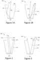
- Figure 1A illustrates a conventional light source 100.
- Conventional light source 100 comprises a light source 120 located inside a light pipe 110 comprising a reflective aperture 150.
- Light pipe 110 and light source 120 are configured to allow output light 130 to exit light pipe 110 in a cone of angles, and to prevent light exiting the light pipe outside of the cone of angles. The light may be prevented from exiting outside of the cone of angles by the presence of the reflective aperture 150. This is described with relation to Figure 1B .
- the reflective aperture 150 reflects incident light 140 that is incident onto aperture 140 such that the light is reflected back towards the light source 120, increasing the amount of useful power output from the conventional light source 100 by providing light recycling. This may a direct reflection from the reflective aperture 150 or indirect, via the sides of the light pipe 110.
- a range of micro Amps to ⁇ 1 Amp (a dynamic range of approximately 1:10 6 ). This may require very complicated and large electronics.
- an LED has an approximately linear relationship between output power and drive current. Therefore, to obtain a dynamic power range of approximately 1:10 6 of power, a drive current range of approximately 1:10 6 is also needed. This may be particularly problematic when the conventional light source 100 is used on a HMD, as this could make the helmet bulky and heavy.
- US 2007/206164 A1 describes a dynamic light source comprising LEDs attached to the inside surfaces of a light recycling cavity.
- the light output of the light recycling cavity can be dynamically changed and is controlled by the respective current sources and control units of the LEDs.
- FIG. 2 illustrates a dynamic light source 200 in accordance with some examples.
- Dynamic light source 200 comprises a first device 210, a first light source 220 and a second light source 230.
- the first light source 220 is located inside first device 210 and the first device 210 is configured to allow light from the first light source 220 to exit the first device 210 in a first cone of angles 240.
- the first device 210 is further configured to reflect light incident outside the first cone of angles 240 back towards the first light source 220, similar to the conventional light source 100 described in relation to Figure 1 .
- Dynamic in this context refers to the fact that the optical power of the dynamic light source 200 may be varied.
- Second light source 230 emits light towards the first light source 220, which is then reflected in a second cone of angles 250 substantially coincident with the first cone of angles. At least due to the fact that light emitted from the second light source 230 is reflected from the first light source 220, the output power of the second cone of angles 250 is attenuated more compared to the output power directly from the first light source 220. This may allow the dynamic light source 200 to have a dynamic range of power or luminance that is greater for the same current range than the dynamic range that would be allowed if the second light source 230 was not used. This is because the second light source 230 may be used to obtain the low power outputs that would conventionally require the first light source 220 to be driven with small electrical currents.
- light output by the dynamic light source 200 from second light source 230 is attenuated more than light output from the first light source 220 by taking advantage of attenuation in the second light source, insertion/output losses, and loss when light is reflected at the first light source. This is counter-intuitive, as normally the losses would be carefully limited.
- the amount of attenuation is based on the intended dynamic power or luminance range of the dynamic light source 200. This may allow substantially similar light sources to be used, with substantially similar drive current demands, but still able obtain a higher dynamic range than would be possible with a single conventional LED.
- the first light source 220 and the second light source 230 may be driven with substantially the same range of input currents, but may result in a different range of output powers from the light source 100. In some examples the output powers may differ by approximately an order of magnitude. In some examples the first light source 220 may be used to output light from the light source 200 with a drive current in the range of ⁇ 0.01 A to ⁇ 1 A and the second light source may output light from the light source 200 as if the first light source was driven with a current the range of ⁇ 1 micro A to ⁇ 0.01 A.
- the attenuation may be based on the square root of the desired optical power range of the dynamic light source 200. For example, if desired dynamic range of optical power is 1:10 6 then the attenuation factor may be greater than approximately the square root of 10 6 , i.e. 1000 (or -30dB). In some examples the attenuation may be greater than approximately 100 (-20db). According to the claimed invention, the attenuation factor is greater than 10 (-10dB).
- the first device 210 comprises a homogenising light pipe. In some examples the first device 210 comprises a tapered light pipe.
- the first device 210 comprises an aperture to allow light to be output in the cone of angles.
- the second light source 230 is located substantially adjacent to the aperture.
- the first light source 220 comprises at least one light emitting diode (LED). In some examples the first light source comprises a plurality of LEDs mounted on a die.
- LED light emitting diode
- Figure 3 illustrates the dynamic light source 200 according to some examples, substantially similar to the description of Figure 2 , however the second light source 230 comprises a fibre optic cable 240.
- the fibre optic cable 240 may be used to couple the light from an external light source into the first device 210. This may allow a conventional light source 100, similar to that described with relation to Figure 1 to be adapted to have the same output power range with a smaller electrical current range without needing to add a second LED to the light source 100.
- the use of the fibre optic cable may also allow a smaller and simpler device.
- references to 'a', 'an', 'first', 'second', etc. do not preclude a plurality.
- the term 'comprising' or "including” does not exclude the presence of other elements.
Landscapes
- Physics & Mathematics (AREA)
- Engineering & Computer Science (AREA)
- General Physics & Mathematics (AREA)
- Optics & Photonics (AREA)
- General Engineering & Computer Science (AREA)
- Transportation (AREA)
- Mechanical Engineering (AREA)
- Chemical & Material Sciences (AREA)
- Combustion & Propulsion (AREA)
- Spectroscopy & Molecular Physics (AREA)
- Multimedia (AREA)
- Signal Processing (AREA)
- Non-Portable Lighting Devices Or Systems Thereof (AREA)
- Led Device Packages (AREA)
- Light Guides In General And Applications Therefor (AREA)
Description
- For some applications it is desirable to have a light source that has a high range of output intensities, for example a light source for a head up display (HUD) or head mounted display (HMD).
-
-
Figures 1A and 1B illustrate a conventional light source. -
Figure 2 illustrates a light source in accordance with some examples. -
Figure 3 illustrates a light source comprising a fibre optic cable in accordance with some examples. -
Figure 1A illustrates aconventional light source 100.Conventional light source 100 comprises alight source 120 located inside alight pipe 110 comprising areflective aperture 150.Light pipe 110 andlight source 120 are configured to allowoutput light 130 to exitlight pipe 110 in a cone of angles, and to prevent light exiting the light pipe outside of the cone of angles. The light may be prevented from exiting outside of the cone of angles by the presence of thereflective aperture 150. This is described with relation toFigure 1B . - The
reflective aperture 150 reflectsincident light 140 that is incident ontoaperture 140 such that the light is reflected back towards thelight source 120, increasing the amount of useful power output from theconventional light source 100 by providing light recycling. This may a direct reflection from thereflective aperture 150 or indirect, via the sides of thelight pipe 110. - However, some applications use very high dynamic ranges of optical power and therefore high current ranges are required. In some examples a range of micro Amps to ~1 Amp (a dynamic range of approximately 1:106). This may require very complicated and large electronics. Typically an LED has an approximately linear relationship between output power and drive current. Therefore, to obtain a dynamic power range of approximately 1:106 of power, a drive current range of approximately 1:106 is also needed. This may be particularly problematic when the
conventional light source 100 is used on a HMD, as this could make the helmet bulky and heavy. -
US 2007/206164 A1 describes a dynamic light source comprising LEDs attached to the inside surfaces of a light recycling cavity. The light output of the light recycling cavity can be dynamically changed and is controlled by the respective current sources and control units of the LEDs. -
Figure 2 illustrates adynamic light source 200 in accordance with some examples.Dynamic light source 200 comprises afirst device 210, afirst light source 220 and asecond light source 230. Thefirst light source 220 is located insidefirst device 210 and thefirst device 210 is configured to allow light from thefirst light source 220 to exit thefirst device 210 in a first cone ofangles 240. Thefirst device 210 is further configured to reflect light incident outside the first cone ofangles 240 back towards thefirst light source 220, similar to theconventional light source 100 described in relation toFigure 1 . Dynamic in this context refers to the fact that the optical power of thedynamic light source 200 may be varied. -
Second light source 230 emits light towards thefirst light source 220, which is then reflected in a second cone ofangles 250 substantially coincident with the first cone of angles. At least due to the fact that light emitted from thesecond light source 230 is reflected from thefirst light source 220, the output power of the second cone ofangles 250 is attenuated more compared to the output power directly from thefirst light source 220. This may allow thedynamic light source 200 to have a dynamic range of power or luminance that is greater for the same current range than the dynamic range that would be allowed if thesecond light source 230 was not used. This is because thesecond light source 230 may be used to obtain the low power outputs that would conventionally require thefirst light source 220 to be driven with small electrical currents. - According to the claimed invention, light output by the
dynamic light source 200 fromsecond light source 230 is attenuated more than light output from thefirst light source 220 by taking advantage of attenuation in the second light source, insertion/output losses, and loss when light is reflected at the first light source. This is counter-intuitive, as normally the losses would be carefully limited. The amount of attenuation is based on the intended dynamic power or luminance range of thedynamic light source 200. This may allow substantially similar light sources to be used, with substantially similar drive current demands, but still able obtain a higher dynamic range than would be possible with a single conventional LED. - In some examples the
first light source 220 and thesecond light source 230 may be driven with substantially the same range of input currents, but may result in a different range of output powers from thelight source 100. In some examples the output powers may differ by approximately an order of magnitude. In some examples thefirst light source 220 may be used to output light from thelight source 200 with a drive current in the range of ~0.01 A to ~1 A and the second light source may output light from thelight source 200 as if the first light source was driven with a current the range of ~1 micro A to ~0.01 A. - In some examples the attenuation may be based on the square root of the desired optical power range of the
dynamic light source 200. For example, if desired dynamic range of optical power is 1:106 then the attenuation factor may be greater than approximately the square root of 106, i.e. 1000 (or -30dB). In some examples the attenuation may be greater than approximately 100 (-20db). According to the claimed invention, the attenuation factor is greater than 10 (-10dB). - In some examples the
first device 210 comprises a homogenising light pipe. In some examples thefirst device 210 comprises a tapered light pipe. - In some examples the
first device 210 comprises an aperture to allow light to be output in the cone of angles. In some examples thesecond light source 230 is located substantially adjacent to the aperture. - In some examples the
first light source 220 comprises at least one light emitting diode (LED). In some examples the first light source comprises a plurality of LEDs mounted on a die. -
Figure 3 illustrates thedynamic light source 200 according to some examples, substantially similar to the description ofFigure 2 , however thesecond light source 230 comprises a fibreoptic cable 240. The fibreoptic cable 240 may be used to couple the light from an external light source into thefirst device 210. This may allow aconventional light source 100, similar to that described with relation toFigure 1 to be adapted to have the same output power range with a smaller electrical current range without needing to add a second LED to thelight source 100. The use of the fibre optic cable may also allow a smaller and simpler device. - Although the present invention has been described in connection with some examples, it is not intended to be limited to the specific form set forth herein. Rather, the scope of the present invention is limited only by the accompanying claims. Additionally, although a feature may appear to be described in connection with particular examples, one skilled in the art would recognize that various features of the described examples may be combined in accordance with the invention. In the claims, the term 'comprising' does not exclude the presence of other elements or steps.
- Furthermore, singular references do not exclude a plurality. Thus, references to 'a', 'an', 'first', 'second', etc. do not preclude a plurality. In the claims, the term 'comprising' or "including" does not exclude the presence of other elements.
Claims (13)
- A dynamic light source (200) for a display, the light source comprisinga first light source (220) located inside a first device (210); a second light source (230);wherein the first device is configured to allow light from the first light source to exit the first device in a first cone of angles and to reflect light incident outside the cone of angles back towards the first light source;wherein the first device is configured such that injected light from the second light source is reflected by the first light source in a second cone of angles substantially coincident with the first cone of angles and that light output by the first device from the second light source is attenuated more than light output by the first light source, and an amount of attenuation is based on an intended dynamic power range of the dynamic light source, wherein the attenuation is greater than a factor of 10.
- The dynamic light source according to claim 1, wherein the attenuation is greater than a factor of 100.
- The dynamic light source according to claim 1, wherein the attenuation is greater than a factor of 1000.
- The dynamic light source according to claim 1, wherein the attenuation is substantially equal to a square root of the intended dynamic power range of the dynamic light source.
- The dynamic light source according to any preceding claim, wherein the first device comprises a homogenising light pipe.
- The dynamic light source according to any preceding claim, wherein first device comprises a tapered light pipe.
- The dynamic light source according to any preceding claim wherein the first device comprises an aperture to allow light to be output in the cone of angles.
- The dynamic light source according to claim 7, wherein the second light source is located substantially adjacent to the aperture.
- The dynamic light source according to any preceding claim wherein the second light source comprises a fibre optic cable (240).
- The dynamic light source according to claim 9, wherein the fibre optic cable is coupled to an external light source.
- The dynamic light source according to any preceding claim, wherein the first light source comprises at least one light emitting diode
- The dynamic light source according to any preceding claim, wherein the first light source comprises a die comprising a plurality of light emitting diodes
- The dynamic light source according to any preceding claim, wherein the first light source and second light source operate using substantially the same range of drive currents.
Applications Claiming Priority (3)
| Application Number | Priority Date | Filing Date | Title |
|---|---|---|---|
| GBGB1917889.6A GB201917889D0 (en) | 2019-12-06 | 2019-12-06 | Light source |
| EP19275144.4A EP3831637A1 (en) | 2019-12-06 | 2019-12-06 | Light source |
| PCT/GB2020/052949 WO2021111103A1 (en) | 2019-12-06 | 2020-11-19 | Light source |
Publications (2)
| Publication Number | Publication Date |
|---|---|
| EP4069546A1 EP4069546A1 (en) | 2022-10-12 |
| EP4069546B1 true EP4069546B1 (en) | 2024-11-06 |
Family
ID=73543300
Family Applications (1)
| Application Number | Title | Priority Date | Filing Date |
|---|---|---|---|
| EP20811430.6A Active EP4069546B1 (en) | 2019-12-06 | 2020-11-19 | Light source |
Country Status (5)
| Country | Link |
|---|---|
| US (1) | US11828455B2 (en) |
| EP (1) | EP4069546B1 (en) |
| ES (1) | ES3001533T3 (en) |
| GB (1) | GB2591846B (en) |
| WO (1) | WO2021111103A1 (en) |
Families Citing this family (3)
| Publication number | Priority date | Publication date | Assignee | Title |
|---|---|---|---|---|
| ME03421B (en) | 2013-06-21 | 2020-01-20 | Karyopharm Therapeutics Inc | 1,2,4-TRIAZOLES AS NUCLEAR TRANSPORT MODULATORS AND USES THEREOF |
| KR102608259B1 (en) | 2014-08-15 | 2023-11-29 | 카리오팜 쎄라퓨틱스, 인코포레이티드 | Polymorphs of selinexor |
| GB2591846B (en) | 2019-12-06 | 2024-08-14 | Bae Systems Plc | Light source |
Family Cites Families (19)
| Publication number | Priority date | Publication date | Assignee | Title |
|---|---|---|---|---|
| US4897771A (en) * | 1987-11-24 | 1990-01-30 | Lumitex, Inc. | Reflector and light system |
| US6280054B1 (en) | 1999-07-02 | 2001-08-28 | Zight Corporation | Image generator having an improved illumination system |
| EP1321902B1 (en) * | 2001-12-20 | 2015-08-12 | MEI, Inc. | Currency acceptor and light source for use therein |
| US7040774B2 (en) | 2003-05-23 | 2006-05-09 | Goldeneye, Inc. | Illumination systems utilizing multiple wavelength light recycling |
| US6960872B2 (en) * | 2003-05-23 | 2005-11-01 | Goldeneye, Inc. | Illumination systems utilizing light emitting diodes and light recycling to enhance output radiance |
| US6995355B2 (en) | 2003-06-23 | 2006-02-07 | Advanced Optical Technologies, Llc | Optical integrating chamber lighting using multiple color sources |
| US7431463B2 (en) | 2004-03-30 | 2008-10-07 | Goldeneye, Inc. | Light emitting diode projection display systems |
| US7025464B2 (en) | 2004-03-30 | 2006-04-11 | Goldeneye, Inc. | Projection display systems utilizing light emitting diodes and light recycling |
| WO2007040540A1 (en) * | 2005-10-05 | 2007-04-12 | Goldeneye, Inc. | Light emitting diode projection display systems |
| US8033693B2 (en) * | 2009-04-30 | 2011-10-11 | Avago Technologies Ecbu Ip (Singapore) Pte. Ltd. | Lighting structure with multiple reflective surfaces |
| JP2011039395A (en) * | 2009-08-17 | 2011-02-24 | Canon Inc | Illuminator and image display device having the same |
| US8517550B2 (en) * | 2010-02-15 | 2013-08-27 | Abl Ip Holding Llc | Phosphor-centric control of color of light |
| WO2011123622A1 (en) * | 2010-04-01 | 2011-10-06 | Wavien, Inc. | Led illumination system with recycled light |
| US20130021793A1 (en) * | 2011-07-22 | 2013-01-24 | Zimmerman Scott M | Recycling light cavity with enhanced reflectivity |
| JP6382305B2 (en) * | 2014-05-09 | 2018-08-29 | マクセル株式会社 | Head-up display device |
| EP3181988A1 (en) * | 2015-12-16 | 2017-06-21 | Ivoclar Vivadent AG | Homogenizer |
| US20180059482A1 (en) | 2016-08-30 | 2018-03-01 | Apple Inc. | Light Diffusers for Backlit Displays |
| GB201705364D0 (en) | 2017-04-03 | 2017-05-17 | Optovate Ltd | Illumination apparatus |
| GB2591846B (en) | 2019-12-06 | 2024-08-14 | Bae Systems Plc | Light source |
-
2020
- 2020-11-19 GB GB2018163.2A patent/GB2591846B/en active Active
- 2020-11-19 EP EP20811430.6A patent/EP4069546B1/en active Active
- 2020-11-19 WO PCT/GB2020/052949 patent/WO2021111103A1/en not_active Ceased
- 2020-11-19 ES ES20811430T patent/ES3001533T3/en active Active
- 2020-11-19 US US17/756,827 patent/US11828455B2/en active Active
Also Published As
| Publication number | Publication date |
|---|---|
| GB202018163D0 (en) | 2021-01-06 |
| US20230024251A1 (en) | 2023-01-26 |
| WO2021111103A1 (en) | 2021-06-10 |
| GB2591846A (en) | 2021-08-11 |
| GB2591846B (en) | 2024-08-14 |
| US11828455B2 (en) | 2023-11-28 |
| EP4069546A1 (en) | 2022-10-12 |
| ES3001533T3 (en) | 2025-03-05 |
Similar Documents
| Publication | Publication Date | Title |
|---|---|---|
| EP4069546B1 (en) | Light source | |
| US7430349B2 (en) | Method for increasing daylight display brightness for helmet mounted displays | |
| US7837370B2 (en) | Low profile side emission TIR lens for LED | |
| WO2019205500A1 (en) | Semiconductor laser beam combining device | |
| WO2021055297A3 (en) | Display device with holographic diffuser display and see-through lens assembly | |
| US10585351B1 (en) | Colinear light source with active optical waveguide coupling | |
| US20130329448A1 (en) | Lighting apparatus with phosphor element | |
| GB2510370A (en) | Fibre Optical Laser Combiner | |
| US9823404B2 (en) | Backlight system | |
| US20150036332A1 (en) | Display illuminating module | |
| CN107923599A (en) | Lighting apparatus for headlight for vehicle | |
| CN104501096A (en) | Reflecting transmission device and laser backlight source with same | |
| EP1601070A3 (en) | Wavelength stabilized laser | |
| US10591657B2 (en) | Optical fiber laser module, lighting device, and treatment device | |
| CN102128418A (en) | Backlight module and liquid crystal display device | |
| US20160341921A1 (en) | Power-by-light architecture for optically remote analog-to-digital converters | |
| KR20140129156A (en) | Backlight light guide | |
| CN105207058A (en) | White laser module, laser display system and laser projection system | |
| EP3831637A1 (en) | Light source | |
| CN202305904U (en) | Optical fiber connector of light-emitting diode (LED) light source | |
| US20070039077A1 (en) | Endoscope | |
| US9448351B2 (en) | Reflector, illuminating device and backlight module using the reflector | |
| US20140160392A1 (en) | Optical fiber for backlight module, backlight module and liquid crystal display device | |
| US20210033870A1 (en) | Optical device and image display apparatus | |
| KR102166400B1 (en) | Switchable laser and fiber based lamphouse for optimal power output in different wavelength bands and pixel sizes |
Legal Events
| Date | Code | Title | Description |
|---|---|---|---|
| STAA | Information on the status of an ep patent application or granted ep patent |
Free format text: STATUS: UNKNOWN |
|
| STAA | Information on the status of an ep patent application or granted ep patent |
Free format text: STATUS: THE INTERNATIONAL PUBLICATION HAS BEEN MADE |
|
| PUAI | Public reference made under article 153(3) epc to a published international application that has entered the european phase |
Free format text: ORIGINAL CODE: 0009012 |
|
| STAA | Information on the status of an ep patent application or granted ep patent |
Free format text: STATUS: REQUEST FOR EXAMINATION WAS MADE |
|
| 17P | Request for examination filed |
Effective date: 20220629 |
|
| AK | Designated contracting states |
Kind code of ref document: A1 Designated state(s): AL AT BE BG CH CY CZ DE DK EE ES FI FR GB GR HR HU IE IS IT LI LT LU LV MC MK MT NL NO PL PT RO RS SE SI SK SM TR |
|
| DAV | Request for validation of the european patent (deleted) | ||
| DAX | Request for extension of the european patent (deleted) | ||
| REG | Reference to a national code |
Ref country code: DE Ref legal event code: R079 Free format text: PREVIOUS MAIN CLASS: B60K0037020000 Ipc: B60K0035000000 Ref document number: 602020040954 Country of ref document: DE |
|
| GRAP | Despatch of communication of intention to grant a patent |
Free format text: ORIGINAL CODE: EPIDOSNIGR1 |
|
| STAA | Information on the status of an ep patent application or granted ep patent |
Free format text: STATUS: GRANT OF PATENT IS INTENDED |
|
| RIC1 | Information provided on ipc code assigned before grant |
Ipc: G02B 6/42 20060101ALN20240619BHEP Ipc: G02B 27/14 20060101ALI20240619BHEP Ipc: G02B 27/10 20060101ALI20240619BHEP Ipc: G02B 27/01 20060101ALI20240619BHEP Ipc: G02B 19/00 20060101ALI20240619BHEP Ipc: F21V 8/00 20060101ALI20240619BHEP Ipc: F21V 7/00 20060101ALI20240619BHEP Ipc: B60K 35/00 20060101AFI20240619BHEP |
|
| INTG | Intention to grant announced |
Effective date: 20240708 |
|
| GRAS | Grant fee paid |
Free format text: ORIGINAL CODE: EPIDOSNIGR3 |
|
| GRAA | (expected) grant |
Free format text: ORIGINAL CODE: 0009210 |
|
| STAA | Information on the status of an ep patent application or granted ep patent |
Free format text: STATUS: THE PATENT HAS BEEN GRANTED |
|
| AK | Designated contracting states |
Kind code of ref document: B1 Designated state(s): AL AT BE BG CH CY CZ DE DK EE ES FI FR GB GR HR HU IE IS IT LI LT LU LV MC MK MT NL NO PL PT RO RS SE SI SK SM TR |
|
| REG | Reference to a national code |
Ref country code: GB Ref legal event code: FG4D |
|
| REG | Reference to a national code |
Ref country code: CH Ref legal event code: EP |
|
| REG | Reference to a national code |
Ref country code: DE Ref legal event code: R096 Ref document number: 602020040954 Country of ref document: DE |
|
| REG | Reference to a national code |
Ref country code: IE Ref legal event code: FG4D |
|
| REG | Reference to a national code |
Ref country code: LT Ref legal event code: MG9D |
|
| REG | Reference to a national code |
Ref country code: NL Ref legal event code: MP Effective date: 20241106 |
|
| PG25 | Lapsed in a contracting state [announced via postgrant information from national office to epo] |
Ref country code: PT Free format text: LAPSE BECAUSE OF FAILURE TO SUBMIT A TRANSLATION OF THE DESCRIPTION OR TO PAY THE FEE WITHIN THE PRESCRIBED TIME-LIMIT Effective date: 20250306 Ref country code: HR Free format text: LAPSE BECAUSE OF FAILURE TO SUBMIT A TRANSLATION OF THE DESCRIPTION OR TO PAY THE FEE WITHIN THE PRESCRIBED TIME-LIMIT Effective date: 20241106 Ref country code: IS Free format text: LAPSE BECAUSE OF FAILURE TO SUBMIT A TRANSLATION OF THE DESCRIPTION OR TO PAY THE FEE WITHIN THE PRESCRIBED TIME-LIMIT Effective date: 20250306 |
|
| PG25 | Lapsed in a contracting state [announced via postgrant information from national office to epo] |
Ref country code: NL Free format text: LAPSE BECAUSE OF FAILURE TO SUBMIT A TRANSLATION OF THE DESCRIPTION OR TO PAY THE FEE WITHIN THE PRESCRIBED TIME-LIMIT Effective date: 20241106 Ref country code: FI Free format text: LAPSE BECAUSE OF FAILURE TO SUBMIT A TRANSLATION OF THE DESCRIPTION OR TO PAY THE FEE WITHIN THE PRESCRIBED TIME-LIMIT Effective date: 20241106 |
|
| REG | Reference to a national code |
Ref country code: AT Ref legal event code: MK05 Ref document number: 1739026 Country of ref document: AT Kind code of ref document: T Effective date: 20241106 |
|
| PG25 | Lapsed in a contracting state [announced via postgrant information from national office to epo] |
Ref country code: BG Free format text: LAPSE BECAUSE OF FAILURE TO SUBMIT A TRANSLATION OF THE DESCRIPTION OR TO PAY THE FEE WITHIN THE PRESCRIBED TIME-LIMIT Effective date: 20241106 |
|
| PG25 | Lapsed in a contracting state [announced via postgrant information from national office to epo] |
Ref country code: NO Free format text: LAPSE BECAUSE OF FAILURE TO SUBMIT A TRANSLATION OF THE DESCRIPTION OR TO PAY THE FEE WITHIN THE PRESCRIBED TIME-LIMIT Effective date: 20250206 |
|
| PG25 | Lapsed in a contracting state [announced via postgrant information from national office to epo] |
Ref country code: AT Free format text: LAPSE BECAUSE OF FAILURE TO SUBMIT A TRANSLATION OF THE DESCRIPTION OR TO PAY THE FEE WITHIN THE PRESCRIBED TIME-LIMIT Effective date: 20241106 Ref country code: LV Free format text: LAPSE BECAUSE OF FAILURE TO SUBMIT A TRANSLATION OF THE DESCRIPTION OR TO PAY THE FEE WITHIN THE PRESCRIBED TIME-LIMIT Effective date: 20241106 Ref country code: GR Free format text: LAPSE BECAUSE OF FAILURE TO SUBMIT A TRANSLATION OF THE DESCRIPTION OR TO PAY THE FEE WITHIN THE PRESCRIBED TIME-LIMIT Effective date: 20250207 |
|
| PG25 | Lapsed in a contracting state [announced via postgrant information from national office to epo] |
Ref country code: PL Free format text: LAPSE BECAUSE OF FAILURE TO SUBMIT A TRANSLATION OF THE DESCRIPTION OR TO PAY THE FEE WITHIN THE PRESCRIBED TIME-LIMIT Effective date: 20241106 |
|
| PG25 | Lapsed in a contracting state [announced via postgrant information from national office to epo] |
Ref country code: RS Free format text: LAPSE BECAUSE OF FAILURE TO SUBMIT A TRANSLATION OF THE DESCRIPTION OR TO PAY THE FEE WITHIN THE PRESCRIBED TIME-LIMIT Effective date: 20250206 |
|
| REG | Reference to a national code |
Ref country code: CH Ref legal event code: PL |
|
| PG25 | Lapsed in a contracting state [announced via postgrant information from national office to epo] |
Ref country code: SM Free format text: LAPSE BECAUSE OF FAILURE TO SUBMIT A TRANSLATION OF THE DESCRIPTION OR TO PAY THE FEE WITHIN THE PRESCRIBED TIME-LIMIT Effective date: 20241106 |
|
| PG25 | Lapsed in a contracting state [announced via postgrant information from national office to epo] |
Ref country code: DK Free format text: LAPSE BECAUSE OF FAILURE TO SUBMIT A TRANSLATION OF THE DESCRIPTION OR TO PAY THE FEE WITHIN THE PRESCRIBED TIME-LIMIT Effective date: 20241106 |
|
| PG25 | Lapsed in a contracting state [announced via postgrant information from national office to epo] |
Ref country code: LU Free format text: LAPSE BECAUSE OF NON-PAYMENT OF DUE FEES Effective date: 20241119 |
|
| REG | Reference to a national code |
Ref country code: CH Ref legal event code: PL |
|
| PG25 | Lapsed in a contracting state [announced via postgrant information from national office to epo] |
Ref country code: EE Free format text: LAPSE BECAUSE OF FAILURE TO SUBMIT A TRANSLATION OF THE DESCRIPTION OR TO PAY THE FEE WITHIN THE PRESCRIBED TIME-LIMIT Effective date: 20241106 |
|
| PG25 | Lapsed in a contracting state [announced via postgrant information from national office to epo] |
Ref country code: CH Free format text: LAPSE BECAUSE OF NON-PAYMENT OF DUE FEES Effective date: 20241130 |
|
| PG25 | Lapsed in a contracting state [announced via postgrant information from national office to epo] |
Ref country code: RO Free format text: LAPSE BECAUSE OF FAILURE TO SUBMIT A TRANSLATION OF THE DESCRIPTION OR TO PAY THE FEE WITHIN THE PRESCRIBED TIME-LIMIT Effective date: 20241106 |
|
| PG25 | Lapsed in a contracting state [announced via postgrant information from national office to epo] |
Ref country code: SK Free format text: LAPSE BECAUSE OF FAILURE TO SUBMIT A TRANSLATION OF THE DESCRIPTION OR TO PAY THE FEE WITHIN THE PRESCRIBED TIME-LIMIT Effective date: 20241106 |
|
| PG25 | Lapsed in a contracting state [announced via postgrant information from national office to epo] |
Ref country code: CZ Free format text: LAPSE BECAUSE OF FAILURE TO SUBMIT A TRANSLATION OF THE DESCRIPTION OR TO PAY THE FEE WITHIN THE PRESCRIBED TIME-LIMIT Effective date: 20241106 |
|
| REG | Reference to a national code |
Ref country code: DE Ref legal event code: R097 Ref document number: 602020040954 Country of ref document: DE |
|
| REG | Reference to a national code |
Ref country code: BE Ref legal event code: MM Effective date: 20241130 |
|
| PG25 | Lapsed in a contracting state [announced via postgrant information from national office to epo] |
Ref country code: SE Free format text: LAPSE BECAUSE OF FAILURE TO SUBMIT A TRANSLATION OF THE DESCRIPTION OR TO PAY THE FEE WITHIN THE PRESCRIBED TIME-LIMIT Effective date: 20241106 |
|
| PLBE | No opposition filed within time limit |
Free format text: ORIGINAL CODE: 0009261 |
|
| STAA | Information on the status of an ep patent application or granted ep patent |
Free format text: STATUS: NO OPPOSITION FILED WITHIN TIME LIMIT |
|
| PG25 | Lapsed in a contracting state [announced via postgrant information from national office to epo] |
Ref country code: MC Free format text: LAPSE BECAUSE OF FAILURE TO SUBMIT A TRANSLATION OF THE DESCRIPTION OR TO PAY THE FEE WITHIN THE PRESCRIBED TIME-LIMIT Effective date: 20241106 |
|
| 26N | No opposition filed |
Effective date: 20250807 |
|
| PG25 | Lapsed in a contracting state [announced via postgrant information from national office to epo] |
Ref country code: BE Free format text: LAPSE BECAUSE OF NON-PAYMENT OF DUE FEES Effective date: 20241130 |
|
| PG25 | Lapsed in a contracting state [announced via postgrant information from national office to epo] |
Ref country code: IE Free format text: LAPSE BECAUSE OF NON-PAYMENT OF DUE FEES Effective date: 20241119 |
|
| PGFP | Annual fee paid to national office [announced via postgrant information from national office to epo] |
Ref country code: DE Payment date: 20251022 Year of fee payment: 6 |
|
| PGFP | Annual fee paid to national office [announced via postgrant information from national office to epo] |
Ref country code: GB Payment date: 20251023 Year of fee payment: 6 |
|
| PGFP | Annual fee paid to national office [announced via postgrant information from national office to epo] |
Ref country code: IT Payment date: 20251022 Year of fee payment: 6 |
|
| PGFP | Annual fee paid to national office [announced via postgrant information from national office to epo] |
Ref country code: FR Payment date: 20251023 Year of fee payment: 6 |
|
| PGFP | Annual fee paid to national office [announced via postgrant information from national office to epo] |
Ref country code: TR Payment date: 20251028 Year of fee payment: 6 |
|
| PGFP | Annual fee paid to national office [announced via postgrant information from national office to epo] |
Ref country code: ES Payment date: 20251201 Year of fee payment: 6 |
|
| PG25 | Lapsed in a contracting state [announced via postgrant information from national office to epo] |
Ref country code: HU Free format text: LAPSE BECAUSE OF FAILURE TO SUBMIT A TRANSLATION OF THE DESCRIPTION OR TO PAY THE FEE WITHIN THE PRESCRIBED TIME-LIMIT; INVALID AB INITIO Effective date: 20201119 |
|
| PG25 | Lapsed in a contracting state [announced via postgrant information from national office to epo] |
Ref country code: CY Free format text: LAPSE BECAUSE OF FAILURE TO SUBMIT A TRANSLATION OF THE DESCRIPTION OR TO PAY THE FEE WITHIN THE PRESCRIBED TIME-LIMIT; INVALID AB INITIO Effective date: 20201119 |