EP4068894A1 - Polling and keep-alive signals for multimedia broadcast multicast service - Google Patents
Polling and keep-alive signals for multimedia broadcast multicast service Download PDFInfo
- Publication number
- EP4068894A1 EP4068894A1 EP22160520.7A EP22160520A EP4068894A1 EP 4068894 A1 EP4068894 A1 EP 4068894A1 EP 22160520 A EP22160520 A EP 22160520A EP 4068894 A1 EP4068894 A1 EP 4068894A1
- Authority
- EP
- European Patent Office
- Prior art keywords
- downlink control
- control channel
- example embodiments
- physical downlink
- user equipment
- Prior art date
- Legal status (The legal status is an assumption and is not a legal conclusion. Google has not performed a legal analysis and makes no representation as to the accuracy of the status listed.)
- Granted
Links
Images



Classifications
-
- H—ELECTRICITY
- H04—ELECTRIC COMMUNICATION TECHNIQUE
- H04W—WIRELESS COMMUNICATION NETWORKS
- H04W74/00—Wireless channel access
- H04W74/002—Transmission of channel access control information
- H04W74/006—Transmission of channel access control information in the downlink, i.e. towards the terminal
-
- H—ELECTRICITY
- H04—ELECTRIC COMMUNICATION TECHNIQUE
- H04W—WIRELESS COMMUNICATION NETWORKS
- H04W72/00—Local resource management
- H04W72/50—Allocation or scheduling criteria for wireless resources
- H04W72/53—Allocation or scheduling criteria for wireless resources based on regulatory allocation policies
-
- H—ELECTRICITY
- H04—ELECTRIC COMMUNICATION TECHNIQUE
- H04L—TRANSMISSION OF DIGITAL INFORMATION, e.g. TELEGRAPHIC COMMUNICATION
- H04L1/00—Arrangements for detecting or preventing errors in the information received
- H04L1/0001—Systems modifying transmission characteristics according to link quality, e.g. power backoff
- H04L1/0036—Systems modifying transmission characteristics according to link quality, e.g. power backoff arrangements specific to the receiver
- H04L1/0038—Blind format detection
-
- H—ELECTRICITY
- H04—ELECTRIC COMMUNICATION TECHNIQUE
- H04L—TRANSMISSION OF DIGITAL INFORMATION, e.g. TELEGRAPHIC COMMUNICATION
- H04L1/00—Arrangements for detecting or preventing errors in the information received
- H04L1/004—Arrangements for detecting or preventing errors in the information received by using forward error control
- H04L1/0056—Systems characterized by the type of code used
- H04L1/0061—Error detection codes
-
- H—ELECTRICITY
- H04—ELECTRIC COMMUNICATION TECHNIQUE
- H04W—WIRELESS COMMUNICATION NETWORKS
- H04W52/00—Power management, e.g. Transmission Power Control [TPC] or power classes
- H04W52/04—Transmission power control [TPC]
- H04W52/30—Transmission power control [TPC] using constraints in the total amount of available transmission power
- H04W52/36—Transmission power control [TPC] using constraints in the total amount of available transmission power with a discrete range or set of values, e.g. step size, ramping or offsets
-
- H—ELECTRICITY
- H04—ELECTRIC COMMUNICATION TECHNIQUE
- H04W—WIRELESS COMMUNICATION NETWORKS
- H04W72/00—Local resource management
- H04W72/04—Wireless resource allocation
- H04W72/044—Wireless resource allocation based on the type of the allocated resource
- H04W72/0466—Wireless resource allocation based on the type of the allocated resource the resource being a scrambling code
-
- H—ELECTRICITY
- H04—ELECTRIC COMMUNICATION TECHNIQUE
- H04W—WIRELESS COMMUNICATION NETWORKS
- H04W72/00—Local resource management
- H04W72/20—Control channels or signalling for resource management
- H04W72/23—Control channels or signalling for resource management in the downlink direction of a wireless link, i.e. towards a terminal
-
- H—ELECTRICITY
- H04—ELECTRIC COMMUNICATION TECHNIQUE
- H04W—WIRELESS COMMUNICATION NETWORKS
- H04W76/00—Connection management
- H04W76/10—Connection setup
- H04W76/11—Allocation or use of connection identifiers
-
- H—ELECTRICITY
- H04—ELECTRIC COMMUNICATION TECHNIQUE
- H04W—WIRELESS COMMUNICATION NETWORKS
- H04W4/00—Services specially adapted for wireless communication networks; Facilities therefor
- H04W4/06—Selective distribution of broadcast services, e.g. multimedia broadcast multicast service [MBMS]; Services to user groups; One-way selective calling services
-
- H—ELECTRICITY
- H04—ELECTRIC COMMUNICATION TECHNIQUE
- H04W—WIRELESS COMMUNICATION NETWORKS
- H04W8/00—Network data management
- H04W8/18—Processing of user or subscriber data, e.g. subscribed services, user preferences or user profiles; Transfer of user or subscriber data
- H04W8/186—Processing of subscriber group data
Definitions
- Some example embodiments may generally relate to mobile or wireless telecommunication systems, such as Long Term Evolution (LTE) or fifth generation (5G) radio access technology or new radio (NR) access technology, or other communications systems.
- LTE Long Term Evolution
- 5G fifth generation
- NR new radio
- certain example embodiments may relate to apparatuses, systems, and/or methods for polling and keep-alive signals for multimedia broadcast multicast service.
- Examples of mobile or wireless telecommunication systems may include the Universal Mobile Telecommunications System (UMTS) Terrestrial Radio Access Network (UTRAN), Long Term Evolution (LTE) Evolved UTRAN (E-UTRAN), LTE-Advanced (LTE-A), MulteFire, LTE-A Pro, and/or fifth generation (5G) radio access technology or new radio (NR) access technology.
- UMTS Universal Mobile Telecommunications System
- UTRAN Universal Mobile Telecommunications System
- LTE Long Term Evolution
- E-UTRAN Evolved UTRAN
- LTE-A LTE-Advanced
- MulteFire LTE-A Pro
- NR new radio
- Fifth generation (5G) wireless systems refer to the next generation (NG) of radio systems and network architecture.
- 5G network technology is mostly based on NR technology, but the 5G (or NG) network can also build on E-UTRAN radio.
- NR will provide bitrates on the order of 10-20 Gbit/s or higher and will support at least enhanced mobile broadband (eMBB) and ultra-reliable low-latency-communication (URLLC) as well as massive machine type communication (mMTC).
- eMBB enhanced mobile broadband
- URLLC ultra-reliable low-latency-communication
- mMTC massive machine type communication
- NR is expected to deliver extreme broadband and ultra-robust, low latency connectivity and massive networking to support the Internet of Things (IoT).
- IoT Internet of Things
- M2M machine-to-machine
- the nodes that can provide radio access functionality to a user equipment are named gNB when built on NR technology and named NG-eNB when built on E-UTRAN radio.
- Some example embodiments may be directed to a method.
- the method may include receiving a physical downlink control channel order addressed to a group-radio network temporary identifier.
- the method may also include performing uplink transmission of a signal in response to the physical downlink control channel order.
- the apparatus may include at least one processor and at least one memory including computer program code.
- the at least one memory and computer program code may be configured to, with the at least one processor, cause the apparatus at least to receive a physical downlink control channel order addressed to a group-radio network temporary identifier.
- the apparatus may also be configured to perform uplink transmission of a signal in response to the physical downlink control channel order.
- the apparatus may include means for receiving a physical downlink control channel order addressed to a group-radio network temporary identifier.
- the apparatus may also include means for performing perform uplink transmission of a signal in response to the physical downlink control channel order.
- a non-transitory computer readable medium may be encoded with instructions that may, when executed in hardware, perform a method.
- the method may include receiving a physical downlink control channel order addressed to a group-radio network temporary identifier.
- the method may also include performing uplink transmission of a signal in response to the physical downlink control channel order.
- the method may include receiving a physical downlink control channel order addressed to a group-radio network temporary identifier.
- the method may also include performing uplink transmission of a signal in response to the physical downlink control channel order.
- Other example embodiments may be directed to an apparatus that may include circuitry configured to receive a physical downlink control channel order addressed to a group-radio network temporary identifier.
- the apparatus may also include circuitry configured to perform uplink transmission of a signal in response to the physical downlink control channel order.
- Certain example embodiments may be directed to a method.
- the method may include configuring a user equipment with a configuration linked to a group-radio network temporary identifier.
- the method may also include sending a physical downlink control channel order to the user equipment addressed to the group-radio network temporary identifier.
- the method may further include receiving an uplink transmission of a signal from the user equipment according to the physical downlink control channel order.
- the apparatus may include at least one processor and at least one memory including computer program code.
- the at least one memory and computer program code may be configured to, with the at least one processor, cause the apparatus at least to configure a user equipment with a configuration linked to a group-radio network temporary identifier.
- the apparatus may also be configured to send a physical downlink control channel order to the user equipment addressed to the group-radio network temporary identifier.
- the apparatus may further be configured to receive an uplink transmission of a signal from the user equipment according to the physical downlink control channel order.
- the apparatus may include means for configuring a user equipment with a configuration linked to a group-radio network temporary identifier.
- the apparatus may also include means for sending a physical downlink control channel order to the user equipment addressed to the group-radio network temporary identifier.
- the apparatus may further include means for receiving receive an uplink transmission of a signal from the user equipment according to the physical downlink control channel order.
- a non-transitory computer readable medium may be encoded with instructions that may, when executed in hardware, perform a method.
- the method may include configuring a user equipment with a configuration linked to a group-radio network temporary identifier.
- the method may also include sending a physical downlink control channel order to the user equipment addressed to the group-radio network temporary identifier.
- the method may further include receiving an uplink transmission of a signal from the user equipment according to the physical downlink control channel order.
- the method may include configuring a user equipment with a configuration linked to a group-radio network temporary identifier.
- the method may also include sending a physical downlink control channel order to the user equipment addressed to the group-radio network temporary identifier.
- the method may further include receiving an uplink transmission of a signal from the user equipment according to the physical downlink control channel order.
- Other example embodiments may be directed to an apparatus that may include circuitry configured to configure a user equipment with a configuration linked to a group-radio network temporary identifier.
- the apparatus may also include circuitry configured to send a physical downlink control channel order to the user equipment addressed to the group-radio network temporary identifier.
- the apparatus may further include circuitry configured to receive an uplink transmission of a signal from the user equipment according to the physical downlink control channel order.
- Certain example embodiments may be directed to a method.
- the method may include receiving a configuration from a network element that is linked to a group-radio network temporary identifier.
- the method may also include periodically transmitting signals in uplink according to the configuration.
- the apparatus may include at least one processor and at least one memory including computer program code.
- the at least one memory and computer program code may be configured to, with the at least one processor, cause the apparatus at least to receive a configuration from a network element that is linked to a group-radio network temporary identifier.
- the apparatus may also be configured to periodically transmit signals in uplink according to the configuration.
- the apparatus may include means for receiving a configuration from a network element that is linked to a group-radio network temporary identifier.
- the apparatus may also include means for periodically transmitting signals in uplink according to the configuration.
- a non-transitory computer readable medium may be encoded with instructions that may, when executed in hardware, perform a method.
- the method may include receiving a configuration from a network element that is linked to a group-radio network temporary identifier.
- the method may also include periodically transmitting signals in uplink according to the configuration.
- the method may include receiving a configuration from a network element that is linked to a group-radio network temporary identifier.
- the method may also include periodically transmitting signals in uplink according to the configuration.
- FIG. 1 may depict an apparatus that may include circuitry configured to receive a configuration from a network element that is linked to a group-radio network temporary identifier.
- the apparatus may also include circuitry configured to periodically transmit signals in uplink according to the configuration.
- Certain example embodiments may be directed to a method.
- the method may include configuring a user equipment with a configuration linked to a group-radio network temporary identifier.
- the method may also include periodically receive signals in uplink according to the configuration.
- the apparatus may include at least one processor and at least one memory including computer program code.
- the at least one memory and computer program code may be configured to, with the at least one processor, cause the apparatus at least to configure a user equipment with a configuration linked to a group-radio network temporary identifier.
- the apparatus may also be configured to periodically receive signals in uplink according to the configuration.
- the apparatus may include means for configuring a user equipment with a configuration linked to a group-radio network temporary identifier.
- the apparatus may also include means for periodically receive signals in uplink according to the configuration.
- a non-transitory computer readable medium may be encoded with instructions that may, when executed in hardware, perform a method.
- the method may include configuring a user equipment with a configuration linked to a group-radio network temporary identifier.
- the method may also include periodically receive signals in uplink according to the configuration.
- the method may include configuring a user equipment with a configuration linked to a group-radio network temporary identifier.
- the method may also include periodically receive signals in uplink according to the configuration.
- FIG. 1 may depict an apparatus that may include circuitry configured to configure a user equipment with a configuration linked to a group-radio network temporary identifier.
- the apparatus may also include circuitry configured to periodically receive signals in uplink according to the configuration.
- 3GPP 3 rd Generation Partnership Project
- MBS multimedia broadcast multicast service
- NR new radio
- MMS multimedia broadcast multicast service
- PDUs protocol data units
- G-RNTI group radio network temporary identifier
- Multiple services may be carried in the same transport block and addressed by the same G-RNTI, or different G-RNTI may be used for different MBS services.
- the network may not know if it should use downlink (DL) resources to transmit an MBS service.
- IDLE state the location of a UE within a tracking area is typically not known.
- INACTIVE state although the network may know how many inactive UEs are within a radio access network (RAN) based notification area (RNA) (since pushing a UE to RRC_INACTIVE is a network decision), the precise location of UEs within an RNA may be unknown.
- RAN radio access network
- RNA notification area
- the network may not know if and how many INACTIVE UEs are receiving a multicast service, if and how many INACTIVE UEs are receiving a broadcast service, and if and how many IDLE UEs are receiving a broadcast service.
- some example embodiments may implement a polling procedure by using a physical downlink control channel (PDCCH) order addressed to a group-common RNTI or G-RNTI.
- PDCCH physical downlink control channel
- the control channel information sent to the users receiving multicast or broadcast service may be scrambled using a group-common RNTI associated with a particular service, which may be signaled to the UE.
- the UEs receiving an MBS service as addressed by the G-RNTI may also receive the PDCCH order and initiate an uplink (UL) transmission of a preamble according to that PDCCH order. Unlike a regular PDCCH order, this may not initiate a full random-access procedure; just the transmission of one UL preamble.
- the network may be able to check whether any UE is receiving the service in the cell. If no UE responds, then the network may know that no UE is receiving this service, and can stop transmitting it.
- the network would be aware of the fact that the UE is receiving multicast data. If the UE is receiving broadcast traffic, the network might not be aware that the UE is receiving the broadcast data. It may further be assumed that the multicast traffic is received by users in RRC CONNECTED and/or RRC_INACTIVE state, whereas broadcast traffic could be received by UEs in any RRC state.
- regular preamble power ramping by the UE may also be used where the network responds with a random-access response message to terminate the power ramping process.
- the UE may first transmit the random-access preamble with low power. If no random-access response is received from the network, the UE may retransmit the preamble with a higher power. The UE may repeat the transmission of the preamble (every time with a higher power) until it receives the related random-access response from the network or reaches the maximum number of preamble transmissions.
- the random-access response may include a medium access control (MAC) sub-header with a random-access preamble ID (RAPID) (i.e., similar to acknowledgment for system information (SI) request).
- MAC medium access control
- RAPID random-access preamble ID
- SI system information
- the UE may be configured by the higher layers - such as a radio resource control (RRC) layer (as described in 3GPP TS 38.331) which uses RRC setup or reconfiguration messages to configure UE regarding the use of G-RNTI based PDCCH order, which may enable the UE to perform blind decoding using an appropriate downlink control information (DCI) format.
- RRC radio resource control
- DCI downlink control information
- the UL transmission of the preamble may be triggered by using a modified group-common PDCCH or DCI, which may be used for scheduling the MBS service.
- another way to assess whether some INACTIVE/IDLE UEs are receiving an MBS service in a cell through energy detection on a given preamble may be via a procedure used to determine whether the service should still be provided (i.e., a keep-alive procedure).
- the procedure may include configuring periodic transmission of preambles.
- the UEs receiving an MBS service may periodically send preambles in UL according to the configuration.
- the configuration e.g., preamble, physical random-access channel (PRACH) resource, and periodicity
- PRACH physical random-access channel
- a preamble may be an example of a shared/common UL resource.
- shared/common UL resource may be used.
- Another example that may be used by UEs with proper time alignment is the physical uplink control channel (PUCCH).
- the shared/common UL resource used for polling and for periodic transmissions may be different or the same.
- different shared/common UL resources may be used to optimize UL power (i.e., limit the risk of excessive inter-cell interference in singular UL resources) and/or retransmissions. For instance, when power ramping is not used for polling, if a large number of UEs respond at the same time, this may generate a power spike at the gNB. Thus, certain example embodiments may provide solutions to this problem by way of the gNB off-loading some UEs to use different shared/common UL resources.
- the gNB may use PDCCH signaling (e.g., a bit within the existing MBS physical downlink control channel (PDCCH) DCI) to request UEs to ramp down/up the power they use to transmit to the common UL resource.
- PDCCH signaling e.g., a bit within the existing MBS physical downlink control channel (PDCCH) DCI
- periodicity of the resources provisioned for periodic transmission of signals may be shorter than the interval at which individual UEs are requested to send the periodic transmission signal. This way, the network may provide new UEs with frequent opportunities to declare their interest for the sake of service, while periodic transmission activity of incumbent UEs is limited.
- the two mechanisms of polling and periodic transmissions may allow the network to decide to either maintain or disable a broadcast/multicast service.
- UEs interested in maintaining the broadcast/multicast service may transmit preambles at regular periods (configured by the network), to effectively "keep alive" the service.
- the network may regularly poll interested UEs. Energy detection on the shared/common UL resource may give the network a rough idea of how many UEs (if any) are receiving the corresponding service(s).
- the absence of "keep alive" energy in the shared/common UL resource for a configurable period of time or a configurable number of interest indication occasions may be used as a trigger to disable the MBS service.
- a two-stage approach may be used. For instance, while the period of the periodic transmission signal (i.e., first stage) may be large (e.g., in the order of seconds), the network may, in case absence of the regular periodic transmission signal is detected, dynamically request/poll (a sequence of) additional periodic transmission signal transmission(s) at short intervals (i.e., second stage), possibly with power ramping, to confirm that there is no more UE interested in the broadcast service. If the periodicity of the resources provisioned for periodic transmission signals are shorter than the interval at which individual UEs are requested to send the periodic transmission signal as described above, these additional transmissions with shorter periodicity may be in the grid of the resources provided for periodic transmissions. A difference here may be that the UEs may now be requested to use each of these transmission opportunities.
- the use of PDCCH order for the purposes of UL preamble message triggering may need the UE to be configured with a new flag within the higher layer, or radio resource control (RRC) configurations related to G-RNTI and other MBS service-related parameters.
- RRC radio resource control
- this enables the UE to monitor or blind decode for the appropriate DCI format containing the PDCCH order in the appropriate MBS service control resource set (CORESET).
- the RRC configurations may be made as part of common or UE-specific search space configurations.
- the information configuring the UE to monitor for the G-RNTI scrambled PDCCH order may be contained in multiple place including but not limited to, for example: 1) configurations related to G-RNTI and other MBS service-related parameters; 2) common search space configuration; and 3) UE-specific search space configuration.
- the triggering of the UL preamble transmission may optionally be done using in-band signaling using the group-common PDCCH (PDCCH with cyclic redundancy check (CRC) scrambled by G-RNTI) DCI.
- PDCCH DCI message containing the MBS service DL scheduling information may also be used to trigger the UL preamble transmission.
- HARQ process number field or new data indicator within the DCI may be used for this purpose.
- these parameters may be considered as mandatory, which enables the UE to estimate the DCI size accurately while blind decoding.
- FIG. 1 illustrates an example flow diagram of a method, according to certain example embodiments.
- the method of FIG. 1 may be performed by a network entity, network node, or a group of multiple network elements in a 3GPP system, such as LTE or 5G-NR.
- the method of FIG. 1 may be performed by a UE, for instance similar to apparatus 10 illustrated in FIG. 5(a) .
- the method of FIG. 1 may include, at 100, receiving a physical downlink control channel order addressed to a group-radio network temporary identifier.
- the method may include performing uplink transmission of a signal in response to the physical downlink control channel order.
- the physical downlink control channel order may be received with cyclic redundancy check scrambled by the group-radio network temporary identifier, and informs a user equipment that the physical downlink control channel order is associated with a particular service being received by the user equipment.
- the method may also include performing blind decoding using an appropriate downlink control information format according to a configuration for blind decoding in searching for the physical downlink control channel order.
- the physical downlink control channel order may include a modified group common physical downlink control channel or downlink control information.
- the transmitted signal may be a random-access preamble.
- the transmitted signal may be a random-access preamble that is transmitted using power ramping, and power ramping may be terminated by reception of a random-access response.
- uplink transmission of the signal may be performed while the apparatus is in an INACTIVE mode or an IDLE mode.
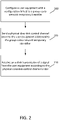
- FIG. 2 illustrates an example flow diagram of another method, according to certain example embodiments.
- the method of FIG. 2 may be performed by a network entity, network node, or a group of multiple network elements in a 3GPP system, such as LTE or 5G-NR.
- the method of FIG. 2 may be performed by a gNB, for instance similar to apparatus 20 illustrated in FIG. 5(b) .
- the method of FIG. 2 may include, at 200, configuring a user equipment with a configuration linked to a group-radio network temporary identifier.
- the method may include sending a physical downlink control channel order to the user equipment addressed to the group-radio network temporary identifier.
- the method may include receiving an uplink transmission of a signal from the user equipment according to the physical downlink control channel order.
- the method may also include determining which user equipment is receiving a multicast service or a broadcast service based on the received uplink transmission of the signal. According to some example embodiments, the method may also include maintaining or disabling the multicast service or the broadcast service based on the received uplink transmission of the signal. According to other example embodiments, the method may further include sending a response to the user equipment to terminate a power ramping process when power ramping is configured for the transmission of the signal.
- the method may also dynamically requesting signal transmissions from the user equipment at predefined intervals include. In other example embodiments, the method may further include off-loading the user equipment to use different uplink resources, and requesting the user equipment via physical downlink control channel signaling to adjust an amount of power used to transmit the uplink transmission.
- FIG. 3 illustrates an example flow diagram of a further method, according to certain example embodiments.
- the method of FIG. 3 may be performed by a network entity, network node, or a group of multiple network elements in a 3GPP system, such as LTE or 5G-NR.
- the method of FIG. 3 may be performed by a UE, for instance similar to apparatus 10 illustrated in FIG. 5(a) .
- the method of FIG. 3 may include, at 300, receiving a configuration from a network element that is linked to a group-radio network temporary identifier. At 305, the method may include periodically transmitting signals in uplink according to the configuration.
- the signals may be random-access preambles.
- the configuration may be linked to a particular service being received by the apparatus.
- the method may further include receiving a periodicity of resources for the signals.
- the periodicity of the resources provisioned for the signals may be shorter than an interval that the apparatus is requested to transmit the signals.
- FIG. 4 illustrates an example flow diagram of yet another method, according to certain example embodiments.
- the method of FIG. 4 may be performed by a network entity, network node, or a group of multiple network elements in a 3GPP system, such as LTE or 5G-NR.
- the method of FIG. 4 may be performed by a gNB, for instance similar to apparatus 20 illustrated in FIG. 5(b) .
- the method of FIG. 4 may include, at 400, configuring a user equipment with a configuration linked to a group-radio network temporary identifier. At 405, the method may include periodically receiving signals in uplink according to the configuration.
- the configuration may be linked to a particular service being received by the user equipment.
- the method may also include provisioning a periodicity of resources for the signals.
- the method may further include requesting the user equipment to transmit the signals at a predefined interval.
- the periodicity of the resources provisioned for the signals may be shorter than the interval that the user equipment is requested to transmit the signals.
- FIG. 5(a) illustrates an apparatus 10 according to certain example embodiments.
- apparatus 10 may be a node or element in a communications network or associated with such a network, such as a UE, mobile equipment (ME), mobile station, mobile device, stationary device, or other device. It should be noted that one of ordinary skill in the art would understand that apparatus 10 may include components or features not shown in FIG. 5(a) .
- apparatus 10 may include one or more processors, one or more computer-readable storage medium (for example, memory, storage, or the like), one or more radio access components (for example, a modem, a transceiver, or the like), and/or a user interface.
- apparatus 10 may be configured to operate using one or more radio access technologies, such as GSM, LTE, LTE-A, NR, 5G, WLAN, WiFi, NB-IoT, Bluetooth, NFC, MulteFire, and/or any other radio access technologies. It should be noted that one of ordinary skill in the art would understand that apparatus 10 may include components or features not shown in FIG. 5(a) .
- apparatus 10 may include or be coupled to a processor 12 for processing information and executing instructions or operations.
- processor 12 may be any type of general or specific purpose processor.
- processor 12 may include one or more of general-purpose computers, special purpose computers, microprocessors, digital signal processors (DSPs), field-programmable gate arrays (FPGAs), application-specific integrated circuits (ASICs), and processors based on a multi-core processor architecture, as examples. While a single processor 12 is shown in FIG. 5(a) , multiple processors may be utilized according to other example embodiments.
- apparatus 10 may include two or more processors that may form a multiprocessor system (e.g., in this case processor 12 may represent a multiprocessor) that may support multiprocessing.
- processor 12 may represent a multiprocessor
- the multiprocessor system may be tightly coupled or loosely coupled (e.g., to form a computer cluster).
- Processor 12 may perform functions associated with the operation of apparatus 10 including, as some examples, precoding of antenna gain/phase parameters, encoding and decoding of individual bits forming a communication message, formatting of information, and overall control of the apparatus 10, including processes illustrated in FIGs. 1 and 3 .
- Apparatus 10 may further include or be coupled to a memory 14 (internal or external), which may be coupled to processor 12, for storing information and instructions that may be executed by processor 12.
- Memory 14 may be one or more memories and of any type suitable to the local application environment, and may be implemented using any suitable volatile or nonvolatile data storage technology such as a semiconductor-based memory device, a magnetic memory device and system, an optical memory device and system, fixed memory, and/or removable memory.
- memory 14 can be comprised of any combination of random access memory (RAM), read only memory (ROM), static storage such as a magnetic or optical disk, hard disk drive (HDD), or any other type of non-transitory machine or computer readable media.
- the instructions stored in memory 14 may include program instructions or computer program code that, when executed by processor 12, enable the apparatus 10 to perform tasks as described herein.
- apparatus 10 may further include or be coupled to (internal or external) a drive or port that is configured to accept and read an external computer readable storage medium, such as an optical disc, USB drive, flash drive, or any other storage medium.
- an external computer readable storage medium such as an optical disc, USB drive, flash drive, or any other storage medium.
- the external computer readable storage medium may store a computer program or software for execution by processor 12 and/or apparatus 10 to perform any of the methods illustrated in FIGs. 1 and 3 .
- apparatus 10 may also include or be coupled to one or more antennas 15 for receiving a downlink signal and for transmitting via an uplink from apparatus 10.
- Apparatus 10 may further include a transceiver 18 configured to transmit and receive information.
- the transceiver 18 may also include a radio interface (e.g., a modem) coupled to the antenna 15.
- the radio interface may correspond to a plurality of radio access technologies including one or more of GSM, LTE, LTE-A, 5G, NR, WLAN, NB-IoT, Bluetooth, BT-LE, NFC, RFID, UWB, and the like.
- the radio interface may include other components, such as filters, converters (for example, digital-to-analog converters and the like), symbol demappers, signal shaping components, an Inverse Fast Fourier Transform (IFFT) module, and the like, to process symbols, such as OFDMA symbols, carried by a downlink or an uplink.
- filters for example, digital-to-analog converters and the like
- symbol demappers for example, digital-to-analog converters and the like
- signal shaping components for example, an Inverse Fast Fourier Transform (IFFT) module, and the like
- IFFT Inverse Fast Fourier Transform
- transceiver 18 may be configured to modulate information on to a carrier waveform for transmission by the antenna(s) 15 and demodulate information received via the antenna(s) 15 for further processing by other elements of apparatus 10.
- transceiver 18 may be capable of transmitting and receiving signals or data directly.
- apparatus 10 may include an input and/or output device (I/O device).
- apparatus 10 may further include a user interface, such as a graphical user interface or touchscreen.
- memory 14 stores software modules that provide functionality when executed by processor 12.
- the modules may include, for example, an operating system that provides operating system functionality for apparatus 10.
- the memory may also store one or more functional modules, such as an application or program, to provide additional functionality for apparatus 10.
- the components of apparatus 10 may be implemented in hardware, or as any suitable combination of hardware and software.
- apparatus 10 may optionally be configured to communicate with apparatus 20 via a wireless or wired communications link 70 according to any radio access technology, such as NR.
- processor 12 and memory 14 may be included in or may form a part of processing circuitry or control circuitry.
- transceiver 18 may be included in or may form a part of transceiving circuitry.
- apparatus 10 may be controlled by memory 14 and processor 12 to receive a physical downlink control channel order addressed to a group-radio network temporary identifier.
- the apparatus 10 may also be controlled by memory 14 and processor 12 to perform uplink transmission of a signal in response to the physical downlink control channel order.
- apparatus 10 may be controlled by memory 14 and processor 12 to receive a configuration from a network element that is linked to a group-radio network temporary identifier. Apparatus 10 may also be controlled by memory 14 and processor 12 to periodically transmit signals in uplink according to the configuration.
- FIG. 5(b) illustrates an apparatus 20 according to certain example embodiments.
- the apparatus 20 may be a node or element in a communications network or associated with such a network, such as a base station, a Node B, an evolved Node B (eNB), 5G Node B or access point, next generation Node B (NG-NB or gNB), NM, and/or WLAN access point, associated with a radio access network (RAN), such as an LTE network, 5G or NR.
- RAN radio access network
- apparatus 20 may include components or features not shown in FIG. 5(b) .
- apparatus 20 may include a processor 22 for processing information and executing instructions or operations.
- processor 22 may be any type of general or specific purpose processor.
- processor 22 may include one or more of general-purpose computers, special purpose computers, microprocessors, digital signal processors (DSPs), field-programmable gate arrays (FPGAs), application-specific integrated circuits (ASICs), and processors based on a multi-core processor architecture, as examples. While a single processor 22 is shown in FIG. 5(b) , multiple processors may be utilized according to other example embodiments.
- apparatus 20 may include two or more processors that may form a multiprocessor system (e.g., in this case processor 22 may represent a multiprocessor) that may support multiprocessing.
- processor 22 may represent a multiprocessor
- the multiprocessor system may be tightly coupled or loosely coupled (e.g., to form a computer cluster).
- processor 22 may perform functions associated with the operation of apparatus 20, which may include, for example, precoding of antenna gain/phase parameters, encoding and decoding of individual bits forming a communication message, formatting of information, and overall control of the apparatus 20, including processes illustrated in FIGs. 2 and 4 .
- Apparatus 20 may further include or be coupled to a memory 24 (internal or external), which may be coupled to processor 22, for storing information and instructions that may be executed by processor 22.
- Memory 24 may be one or more memories and of any type suitable to the local application environment, and may be implemented using any suitable volatile or nonvolatile data storage technology such as a semiconductor-based memory device, a magnetic memory device and system, an optical memory device and system, fixed memory, and/or removable memory.
- memory 24 can be comprised of any combination of random access memory (RAM), read only memory (ROM), static storage such as a magnetic or optical disk, hard disk drive (HDD), or any other type of non-transitory machine or computer readable media.
- the instructions stored in memory 24 may include program instructions or computer program code that, when executed by processor 22, enable the apparatus 20 to perform tasks as described herein.
- apparatus 20 may further include or be coupled to (internal or external) a drive or port that is configured to accept and read an external computer readable storage medium, such as an optical disc, USB drive, flash drive, or any other storage medium.
- an external computer readable storage medium such as an optical disc, USB drive, flash drive, or any other storage medium.
- the external computer readable storage medium may store a computer program or software for execution by processor 22 and/or apparatus 20 to perform the methods illustrated in FIGs. 2 and 4 .
- apparatus 20 may also include or be coupled to one or more antennas 25 for transmitting and receiving signals and/or data to and from apparatus 20.
- Apparatus 20 may further include or be coupled to a transceiver 28 configured to transmit and receive information.
- the transceiver 28 may include, for example, a plurality of radio interfaces that may be coupled to the antenna(s) 25.
- the radio interfaces may correspond to a plurality of radio access technologies including one or more of GSM, NB-IoT, LTE, 5G, WLAN, Bluetooth, BT-LE, NFC, radio frequency identifier (RFID), ultrawideband (UWB), MulteFire, and the like.
- the radio interface may include components, such as filters, converters (for example, digital-to-analog converters and the like), mappers, a Fast Fourier Transform (FFT) module, and the like, to generate symbols for a transmission via one or more downlinks and to receive symbols (for example, via an uplink).
- filters for example, digital-to-analog converters and the like
- mappers for example, mappers
- FFT Fast Fourier Transform
- transceiver 28 may be configured to modulate information on to a carrier waveform for transmission by the antenna(s) 25 and demodulate information received via the antenna(s) 25 for further processing by other elements of apparatus 20.
- transceiver 18 may be capable of transmitting and receiving signals or data directly.
- apparatus 20 may include an input and/or output device (I/O device).
- memory 24 may store software modules that provide functionality when executed by processor 22.
- the modules may include, for example, an operating system that provides operating system functionality for apparatus 20.
- the memory may also store one or more functional modules, such as an application or program, to provide additional functionality for apparatus 20.
- the components of apparatus 20 may be implemented in hardware, or as any suitable combination of hardware and software.
- processor 22 and memory 24 may be included in or may form a part of processing circuitry or control circuitry.
- transceiver 28 may be included in or may form a part of transceiving circuitry.
- circuitry may refer to hardware-only circuitry implementations (e.g., analog and/or digital circuitry), combinations of hardware circuits and software, combinations of analog and/or digital hardware circuits with software/firmware, any portions of hardware processor(s) with software (including digital signal processors) that work together to cause an apparatus (e.g., apparatus 10 and 20) to perform various functions, and/or hardware circuit(s) and/or processor(s), or portions thereof, that use software for operation but where the software may not be present when it is not needed for operation.
- hardware-only circuitry implementations e.g., analog and/or digital circuitry
- combinations of hardware circuits and software combinations of analog and/or digital hardware circuits with software/firmware, any portions of hardware processor(s) with software (including digital signal processors) that work together to cause an apparatus (e.g., apparatus 10 and 20) to perform various functions, and/or hardware circuit(s) and/or processor(s), or portions thereof, that use software for operation but where the software may not be present when it is not needed
- circuitry may also cover an implementation of merely a hardware circuit or processor (or multiple processors), or portion of a hardware circuit or processor, and its accompanying software and/or firmware.
- circuitry may also cover, for example, a baseband integrated circuit in a server, cellular network node or device, or other computing or network device.
- apparatus 20 may be controlled by memory 24 and processor 22 to configure a user equipment with a configuration linked to a group-radio network temporary identifier.
- Apparatus 20 may also be controlled by memory 24 and processor 22 to send a physical downlink control channel order to the user equipment addressed to the group-radio network temporary identifier.
- Apparatus 20 may further be controlled by memory 24 and processor 22 to receive an uplink transmission of a signal from the user equipment according to the physical downlink control channel order.
- apparatus 20 may be controlled by memory 24 and processor 22 to configure a user equipment with a configuration linked to a group-radio network temporary identifier. Apparatus 20 may also be controlled by memory 24 and processor 22 to periodically receive signals in uplink according to the configuration.
- Certain example embodiments may be directed to an apparatus that includes means for receiving a physical downlink control channel order addressed to a group-radio network temporary identifier.
- the apparatus may also include means for performing uplink transmission of a signal in response to the physical downlink control channel order.
- FIG. 1 For example embodiments, may be directed to an apparatus that includes means for receiving a configuration from a network element that is linked to a group-radio network temporary identifier.
- the apparatus may also include means for periodically transmitting signals in uplink according to the configuration.
- Other example embodiments may be directed to an apparatus that includes means for configuring a user equipment with a configuration linked to a group-radio network temporary identifier.
- the apparatus may also include means for sending a physical downlink control channel order to the user equipment addressed to the group-radio network temporary identifier.
- the apparatus may further include means for receiving an uplink transmission of a signal from the user equipment according to the physical downlink control channel order.
- Additional example embodiments may be directed to an apparatus that includes means for configuring a user equipment with a configuration linked to a group-radio network temporary identifier.
- the apparatus may also include means for periodically receiving signals in uplink according to the configuration.
- Certain example embodiments described herein provide several technical improvements, enhancements, and /or advantages.
- the network may be possible to enable the network to decide to either maintain or disable a broadcast/multicast service.
- the RRC configurations may be made as part of the common or UE-specific search space configurations.
- a computer program product may include one or more computer-executable components which, when the program is run, are configured to carry out some example embodiments.
- the one or more computer-executable components may be at least one software code or portions of it. Modifications and configurations required for implementing functionality of certain example embodiments may be performed as routine(s), which may be implemented as added or updated software routine(s). Software routine(s) may be downloaded into the apparatus.
- software or a computer program code or portions of it may be in a source code form, object code form, or in some intermediate form, and it may be stored in some sort of carrier, distribution medium, or computer readable medium, which may be any entity or device capable of carrying the program.
- carrier may include a record medium, computer memory, read-only memory, photoelectrical and/or electrical carrier signal, telecommunications signal, and software distribution package, for example.
- the computer program may be executed in a single electronic digital computer or it may be distributed amongst a number of computers.
- the computer readable medium or computer readable storage medium may be a non-transitory medium.
- the functionality may be performed by hardware or circuitry included in an apparatus (e.g., apparatus 10 or apparatus 20), for example through the use of an application specific integrated circuit (ASIC), a programmable gate array (PGA), a field programmable gate array (FPGA), or any other combination of hardware and software.
- ASIC application specific integrated circuit
- PGA programmable gate array
- FPGA field programmable gate array
- the functionality may be implemented as a signal, a non-tangible means that can be carried by an electromagnetic signal downloaded from the Internet or other network.
- an apparatus such as a node, device, or a corresponding component, may be configured as circuitry, a computer or a microprocessor, such as single-chip computer element, or as a chipset, including at least a memory for providing storage capacity used for arithmetic operation and an operation processor for executing the arithmetic operation.
Landscapes
- Engineering & Computer Science (AREA)
- Computer Networks & Wireless Communication (AREA)
- Signal Processing (AREA)
- Quality & Reliability (AREA)
- Mobile Radio Communication Systems (AREA)
Abstract
Description
- Some example embodiments may generally relate to mobile or wireless telecommunication systems, such as Long Term Evolution (LTE) or fifth generation (5G) radio access technology or new radio (NR) access technology, or other communications systems. For example, certain example embodiments may relate to apparatuses, systems, and/or methods for polling and keep-alive signals for multimedia broadcast multicast service.
- Examples of mobile or wireless telecommunication systems may include the Universal Mobile Telecommunications System (UMTS) Terrestrial Radio Access Network (UTRAN), Long Term Evolution (LTE) Evolved UTRAN (E-UTRAN), LTE-Advanced (LTE-A), MulteFire, LTE-A Pro, and/or fifth generation (5G) radio access technology or new radio (NR) access technology. Fifth generation (5G) wireless systems refer to the next generation (NG) of radio systems and network architecture. 5G network technology is mostly based on NR technology, but the 5G (or NG) network can also build on E-UTRAN radio. It is estimated that NR will provide bitrates on the order of 10-20 Gbit/s or higher and will support at least enhanced mobile broadband (eMBB) and ultra-reliable low-latency-communication (URLLC) as well as massive machine type communication (mMTC). NR is expected to deliver extreme broadband and ultra-robust, low latency connectivity and massive networking to support the Internet of Things (IoT). With IoT and machine-to-machine (M2M) communication becoming more widespread, there will be a growing need for networks that meet the needs of lower power, low data rate, and long battery life. It is noted that, in 5G, the nodes that can provide radio access functionality to a user equipment (i.e., similar to Node B in UTRAN or eNB in LTE) are named gNB when built on NR technology and named NG-eNB when built on E-UTRAN radio.
- Some example embodiments may be directed to a method. The method may include receiving a physical downlink control channel order addressed to a group-radio network temporary identifier. The method may also include performing uplink transmission of a signal in response to the physical downlink control channel order.
- Other example embodiments may be directed to an apparatus. The apparatus may include at least one processor and at least one memory including computer program code. The at least one memory and computer program code may be configured to, with the at least one processor, cause the apparatus at least to receive a physical downlink control channel order addressed to a group-radio network temporary identifier. The apparatus may also be configured to perform uplink transmission of a signal in response to the physical downlink control channel order.
- Other example embodiments may be directed to an apparatus. The apparatus may include means for receiving a physical downlink control channel order addressed to a group-radio network temporary identifier. The apparatus may also include means for performing perform uplink transmission of a signal in response to the physical downlink control channel order.
- In accordance with other example embodiments, a non-transitory computer readable medium may be encoded with instructions that may, when executed in hardware, perform a method. The method may include receiving a physical downlink control channel order addressed to a group-radio network temporary identifier. The method may also include performing uplink transmission of a signal in response to the physical downlink control channel order.
- Other example embodiments may be directed to a computer program product that performs a method. The method may include receiving a physical downlink control channel order addressed to a group-radio network temporary identifier. The method may also include performing uplink transmission of a signal in response to the physical downlink control channel order.
- Other example embodiments may be directed to an apparatus that may include circuitry configured to receive a physical downlink control channel order addressed to a group-radio network temporary identifier. The apparatus may also include circuitry configured to perform uplink transmission of a signal in response to the physical downlink control channel order.
- Certain example embodiments may be directed to a method. The method may include configuring a user equipment with a configuration linked to a group-radio network temporary identifier. The method may also include sending a physical downlink control channel order to the user equipment addressed to the group-radio network temporary identifier. The method may further include receiving an uplink transmission of a signal from the user equipment according to the physical downlink control channel order.
- Other example embodiments may be directed to an apparatus. The apparatus may include at least one processor and at least one memory including computer program code. The at least one memory and computer program code may be configured to, with the at least one processor, cause the apparatus at least to configure a user equipment with a configuration linked to a group-radio network temporary identifier. The apparatus may also be configured to send a physical downlink control channel order to the user equipment addressed to the group-radio network temporary identifier. The apparatus may further be configured to receive an uplink transmission of a signal from the user equipment according to the physical downlink control channel order.
- Other example embodiments may be directed to an apparatus. The apparatus may include means for configuring a user equipment with a configuration linked to a group-radio network temporary identifier. The apparatus may also include means for sending a physical downlink control channel order to the user equipment addressed to the group-radio network temporary identifier. The apparatus may further include means for receiving receive an uplink transmission of a signal from the user equipment according to the physical downlink control channel order.
- In accordance with other example embodiments, a non-transitory computer readable medium may be encoded with instructions that may, when executed in hardware, perform a method. The method may include configuring a user equipment with a configuration linked to a group-radio network temporary identifier. The method may also include sending a physical downlink control channel order to the user equipment addressed to the group-radio network temporary identifier. The method may further include receiving an uplink transmission of a signal from the user equipment according to the physical downlink control channel order.
- Other example embodiments may be directed to a computer program product that performs a method. The method may include configuring a user equipment with a configuration linked to a group-radio network temporary identifier. The method may also include sending a physical downlink control channel order to the user equipment addressed to the group-radio network temporary identifier. The method may further include receiving an uplink transmission of a signal from the user equipment according to the physical downlink control channel order.
- Other example embodiments may be directed to an apparatus that may include circuitry configured to configure a user equipment with a configuration linked to a group-radio network temporary identifier. The apparatus may also include circuitry configured to send a physical downlink control channel order to the user equipment addressed to the group-radio network temporary identifier. The apparatus may further include circuitry configured to receive an uplink transmission of a signal from the user equipment according to the physical downlink control channel order.
- Certain example embodiments may be directed to a method. The method may include receiving a configuration from a network element that is linked to a group-radio network temporary identifier. The method may also include periodically transmitting signals in uplink according to the configuration.
- Other example embodiments may be directed to an apparatus. The apparatus may include at least one processor and at least one memory including computer program code. The at least one memory and computer program code may be configured to, with the at least one processor, cause the apparatus at least to receive a configuration from a network element that is linked to a group-radio network temporary identifier. The apparatus may also be configured to periodically transmit signals in uplink according to the configuration.
- Other example embodiments may be directed to an apparatus. The apparatus may include means for receiving a configuration from a network element that is linked to a group-radio network temporary identifier. The apparatus may also include means for periodically transmitting signals in uplink according to the configuration.
- In accordance with other example embodiments, a non-transitory computer readable medium may be encoded with instructions that may, when executed in hardware, perform a method. The method may include receiving a configuration from a network element that is linked to a group-radio network temporary identifier. The method may also include periodically transmitting signals in uplink according to the configuration.
- Other example embodiments may be directed to a computer program product that performs a method. The method may include receiving a configuration from a network element that is linked to a group-radio network temporary identifier. The method may also include periodically transmitting signals in uplink according to the configuration.
- Other example embodiments may be directed to an apparatus that may include circuitry configured to receive a configuration from a network element that is linked to a group-radio network temporary identifier. The apparatus may also include circuitry configured to periodically transmit signals in uplink according to the configuration.
- Certain example embodiments may be directed to a method. The method may include configuring a user equipment with a configuration linked to a group-radio network temporary identifier. The method may also include periodically receive signals in uplink according to the configuration.
- Other example embodiments may be directed to an apparatus. The apparatus may include at least one processor and at least one memory including computer program code. The at least one memory and computer program code may be configured to, with the at least one processor, cause the apparatus at least to configure a user equipment with a configuration linked to a group-radio network temporary identifier. The apparatus may also be configured to periodically receive signals in uplink according to the configuration.
- Other example embodiments may be directed to an apparatus. The apparatus may include means for configuring a user equipment with a configuration linked to a group-radio network temporary identifier. The apparatus may also include means for periodically receive signals in uplink according to the configuration.
- In accordance with other example embodiments, a non-transitory computer readable medium may be encoded with instructions that may, when executed in hardware, perform a method. The method may include configuring a user equipment with a configuration linked to a group-radio network temporary identifier. The method may also include periodically receive signals in uplink according to the configuration.
- Other example embodiments may be directed to a computer program product that performs a method. The method may include configuring a user equipment with a configuration linked to a group-radio network temporary identifier. The method may also include periodically receive signals in uplink according to the configuration.
- Other example embodiments may be directed to an apparatus that may include circuitry configured to configure a user equipment with a configuration linked to a group-radio network temporary identifier. The apparatus may also include circuitry configured to periodically receive signals in uplink according to the configuration.
- For proper understanding of example embodiments, reference should be made to the accompanying drawings, wherein:
-
FIG. 1 illustrates an example flow diagram of a method, according to certain example embodiments. -
FIG. 2 illustrates an example flow diagram of another method, according to certain example embodiments. -
FIG. 3 illustrates an example flow diagram of yet another method, according to certain example embodiments. -
FIG. 4 illustrates an example flow diagram of a further method, according to certain example embodiments. -
FIG. 5(a) illustrates an apparatus, according to certain example embodiments. -
FIG. 5(b) illustrates another apparatus, according to certain example embodiments. - It will be readily understood that the components of certain example embodiments, as generally described and illustrated in the figures herein, may be arranged and designed in a wide variety of different configurations. The following is a detailed description of some example embodiments of systems, methods, apparatuses, and computer program products for polling and keep-alive signals for multimedia broadcast multicast service.
- The features, structures, or characteristics of example embodiments described throughout this specification may be combined in any suitable manner in one or more example embodiments. For example, the usage of the phrases "certain embodiments," "an example embodiment," "some embodiments," or other similar language, throughout this specification refers to the fact that a particular feature, structure, or characteristic described in connection with an embodiment may be included in at least one embodiment. Thus, appearances of the phrases "in certain embodiments," "an example embodiment," "in some embodiments," "in other embodiments," or other similar language, throughout this specification do not necessarily refer to the same group of embodiments, and the described features, structures, or characteristics may be combined in any suitable manner in one or more example embodiments.
- 3rd Generation Partnership Project (3GPP) provides support of multimedia broadcast multicast service (MBMS) for new radio (NR). For instance, multicast reception in RRC-CONNECTED state has been agreed upon in RAN2, and broadcast reception in IDLE, CONNECTED, and INACTIVE states have been agreed upon. Additionally, multicast broadcast services (MBS) may be carried in protocol data units (PDUs) conveyed in transport blocks addressed by a group radio network temporary identifier (G-RNTI). Multiple services may be carried in the same transport block and addressed by the same G-RNTI, or different G-RNTI may be used for different MBS services.
- Not knowing whether INACTIVE and IDLE user equipment (UEs) are receiving an MBS service, the network may not know if it should use downlink (DL) resources to transmit an MBS service. In IDLE state, the location of a UE within a tracking area is typically not known. In INACTIVE state, although the network may know how many inactive UEs are within a radio access network (RAN) based notification area (RNA) (since pushing a UE to RRC_INACTIVE is a network decision), the precise location of UEs within an RNA may be unknown. In other words, in a given cell, the network may not know if and how many INACTIVE UEs are receiving a multicast service, if and how many INACTIVE UEs are receiving a broadcast service, and if and how many IDLE UEs are receiving a broadcast service.
- A method relying on a group wake-up or trigger signal as a counting procedure of how many UEs are receiving an MBS service has been discussed. An alternative suggests having multiple UEs transmit the same preamble and estimating the number of UEs from the received signal strength. However, this does not provide a way to know what kind of DL signal should be used. Thus, certain example embodiments provide solution(s) to assess whether some INACTIVE/IDLE UEs are receiving an MBS service in a cell.
- According to certain example embodiments, it may be possible to assess whether some INACTIVE/IDLE UEs are receiving an MBS service in a cell through energy detection on a given preamble. For instance, some example embodiments may implement a polling procedure by using a physical downlink control channel (PDCCH) order addressed to a group-common RNTI or G-RNTI. This implies that the control channel information sent to the users receiving multicast or broadcast service may be scrambled using a group-common RNTI associated with a particular service, which may be signaled to the UE. Specifically, in certain example embodiments, the UEs receiving an MBS service as addressed by the G-RNTI may also receive the PDCCH order and initiate an uplink (UL) transmission of a preamble according to that PDCCH order. Unlike a regular PDCCH order, this may not initiate a full random-access procedure; just the transmission of one UL preamble. According to certain example embodiments, by sending PDCCH order using the G-RNTI of the MBS service, the network may be able to check whether any UE is receiving the service in the cell. If no UE responds, then the network may know that no UE is receiving this service, and can stop transmitting it.
- If the UE is receiving multicast traffic, it may be assumed that the network would be aware of the fact that the UE is receiving multicast data. If the UE is receiving broadcast traffic, the network might not be aware that the UE is receiving the broadcast data. It may further be assumed that the multicast traffic is received by users in RRC CONNECTED and/or RRC_INACTIVE state, whereas broadcast traffic could be received by UEs in any RRC state.
- According to certain example embodiments, regular preamble power ramping by the UE (as described in 3GPP TS 38.321) may also be used where the network responds with a random-access response message to terminate the power ramping process. When power ramping is applied, the UE may first transmit the random-access preamble with low power. If no random-access response is received from the network, the UE may retransmit the preamble with a higher power. The UE may repeat the transmission of the preamble (every time with a higher power) until it receives the related random-access response from the network or reaches the maximum number of preamble transmissions. In certain example embodiments, the random-access response may include a medium access control (MAC) sub-header with a random-access preamble ID (RAPID) (i.e., similar to acknowledgment for system information (SI) request). Thus, no Msg3 is transmitted by the UE. Whether one preamble or multiple preambles with power ramping is used may be configured by the network.
- In certain example embodiments, the UE may be configured by the higher layers - such as a radio resource control (RRC) layer (as described in 3GPP TS 38.331) which uses RRC setup or reconfiguration messages to configure UE regarding the use of G-RNTI based PDCCH order, which may enable the UE to perform blind decoding using an appropriate downlink control information (DCI) format. In other example embodiments, the UL transmission of the preamble may be triggered by using a modified group-common PDCCH or DCI, which may be used for scheduling the MBS service.
- According to other example embodiments, another way to assess whether some INACTIVE/IDLE UEs are receiving an MBS service in a cell through energy detection on a given preamble may be via a procedure used to determine whether the service should still be provided (i.e., a keep-alive procedure). For instance, in certain example embodiments, the procedure may include configuring periodic transmission of preambles. Specifically, the UEs receiving an MBS service may periodically send preambles in UL according to the configuration. According to certain example embodiments, the configuration (e.g., preamble, physical random-access channel (PRACH) resource, and periodicity) may be linked to a particular G-RNTI, or to a particular service. To avoid possible collisions with preamble transmissions from regular random-access procedures from other UEs, certain example embodiments may employ resource segregation. According to some example embodiments, a preamble may be an example of a shared/common UL resource. As described herein, shared/common UL resource may be used. Another example that may be used by UEs with proper time alignment is the physical uplink control channel (PUCCH). According to certain example embodiments, the shared/common UL resource used for polling and for periodic transmissions may be different or the same.
- In certain example embodiments, different shared/common UL resources may be used to optimize UL power (i.e., limit the risk of excessive inter-cell interference in singular UL resources) and/or retransmissions. For instance, when power ramping is not used for polling, if a large number of UEs respond at the same time, this may generate a power spike at the gNB. Thus, certain example embodiments may provide solutions to this problem by way of the gNB off-loading some UEs to use different shared/common UL resources. In other example embodiments, the gNB may use PDCCH signaling (e.g., a bit within the existing MBS physical downlink control channel (PDCCH) DCI) to request UEs to ramp down/up the power they use to transmit to the common UL resource.
- According to certain example embodiments, periodicity of the resources provisioned for periodic transmission of signals may be shorter than the interval at which individual UEs are requested to send the periodic transmission signal. This way, the network may provide new UEs with frequent opportunities to declare their interest for the sake of service, while periodic transmission activity of incumbent UEs is limited.
- In certain example embodiments, the two mechanisms of polling and periodic transmissions may allow the network to decide to either maintain or disable a broadcast/multicast service. UEs interested in maintaining the broadcast/multicast service may transmit preambles at regular periods (configured by the network), to effectively "keep alive" the service. Alternatively, or as a complementary measure, in other example embodiments, the network may regularly poll interested UEs. Energy detection on the shared/common UL resource may give the network a rough idea of how many UEs (if any) are receiving the corresponding service(s). In certain example embodiments, the absence of "keep alive" energy in the shared/common UL resource for a configurable period of time or a configurable number of interest indication occasions may be used as a trigger to disable the MBS service.
- According to certain example embodiments, a two-stage approach may be used. For instance, while the period of the periodic transmission signal (i.e., first stage) may be large (e.g., in the order of seconds), the network may, in case absence of the regular periodic transmission signal is detected, dynamically request/poll (a sequence of) additional periodic transmission signal transmission(s) at short intervals (i.e., second stage), possibly with power ramping, to confirm that there is no more UE interested in the broadcast service. If the periodicity of the resources provisioned for periodic transmission signals are shorter than the interval at which individual UEs are requested to send the periodic transmission signal as described above, these additional transmissions with shorter periodicity may be in the grid of the resources provided for periodic transmissions. A difference here may be that the UEs may now be requested to use each of these transmission opportunities.
- In certain example embodiments, the use of PDCCH order for the purposes of UL preamble message triggering (i.e., second stage when used in combination with periodic signals) may need the UE to be configured with a new flag within the higher layer, or radio resource control (RRC) configurations related to G-RNTI and other MBS service-related parameters. According to certain example embodiments, this enables the UE to monitor or blind decode for the appropriate DCI format containing the PDCCH order in the appropriate MBS service control resource set (CORESET). Additionally, the RRC configurations may be made as part of common or UE-specific search space configurations. For instance, in certain example embodiments, the information configuring the UE to monitor for the G-RNTI scrambled PDCCH order may be contained in multiple place including but not limited to, for example: 1) configurations related to G-RNTI and other MBS service-related parameters; 2) common search space configuration; and 3) UE-specific search space configuration.
- According to certain example embodiments, the triggering of the UL preamble transmission may optionally be done using in-band signaling using the group-common PDCCH (PDCCH with cyclic redundancy check (CRC) scrambled by G-RNTI) DCI. If this option is used, the PDCCH DCI message containing the MBS service DL scheduling information may also be used to trigger the UL preamble transmission. For example, since IDLE/INACTIVE UEs may not transmit hybrid automatic repeat request (HARQ) feedback, HARQ process number field or new data indicator within the DCI may be used for this purpose. In this example, these parameters may be considered as mandatory, which enables the UE to estimate the DCI size accurately while blind decoding.
-
FIG. 1 illustrates an example flow diagram of a method, according to certain example embodiments. In an example embodiment, the method ofFIG. 1 may be performed by a network entity, network node, or a group of multiple network elements in a 3GPP system, such as LTE or 5G-NR. For instance, in an example embodiment, the method ofFIG. 1 may be performed by a UE, for instance similar toapparatus 10 illustrated inFIG. 5(a) . - According to certain example embodiments, the method of
FIG. 1 may include, at 100, receiving a physical downlink control channel order addressed to a group-radio network temporary identifier. At 105, the method may include performing uplink transmission of a signal in response to the physical downlink control channel order. - According to certain example embodiments, the physical downlink control channel order may be received with cyclic redundancy check scrambled by the group-radio network temporary identifier, and informs a user equipment that the physical downlink control channel order is associated with a particular service being received by the user equipment. According to other example embodiments, the method may also include performing blind decoding using an appropriate downlink control information format according to a configuration for blind decoding in searching for the physical downlink control channel order. According to some example embodiments, the physical downlink control channel order may include a modified group common physical downlink control channel or downlink control information.
- In some example embodiments, the transmitted signal may be a random-access preamble. In some example embodiments, the transmitted signal may be a random-access preamble that is transmitted using power ramping, and power ramping may be terminated by reception of a random-access response. In other example embodiments, uplink transmission of the signal may be performed while the apparatus is in an INACTIVE mode or an IDLE mode.
-
FIG. 2 illustrates an example flow diagram of another method, according to certain example embodiments. In an example embodiment, the method ofFIG. 2 may be performed by a network entity, network node, or a group of multiple network elements in a 3GPP system, such as LTE or 5G-NR. For instance, in an example embodiment, the method ofFIG. 2 may be performed by a gNB, for instance similar toapparatus 20 illustrated inFIG. 5(b) . - According to certain example embodiments, the method of
FIG. 2 may include, at 200, configuring a user equipment with a configuration linked to a group-radio network temporary identifier. At 205, the method may include sending a physical downlink control channel order to the user equipment addressed to the group-radio network temporary identifier. At 210, the method may include receiving an uplink transmission of a signal from the user equipment according to the physical downlink control channel order. - According to certain example embodiments, the method may also include determining which user equipment is receiving a multicast service or a broadcast service based on the received uplink transmission of the signal. According to some example embodiments, the method may also include maintaining or disabling the multicast service or the broadcast service based on the received uplink transmission of the signal. According to other example embodiments, the method may further include sending a response to the user equipment to terminate a power ramping process when power ramping is configured for the transmission of the signal.
- In certain example embodiments, the method may also dynamically requesting signal transmissions from the user equipment at predefined intervals include. In other example embodiments, the method may further include off-loading the user equipment to use different uplink resources, and requesting the user equipment via physical downlink control channel signaling to adjust an amount of power used to transmit the uplink transmission.
-
FIG. 3 illustrates an example flow diagram of a further method, according to certain example embodiments. In an example embodiment, the method ofFIG. 3 may be performed by a network entity, network node, or a group of multiple network elements in a 3GPP system, such as LTE or 5G-NR. For instance, in an example embodiment, the method ofFIG. 3 may be performed by a UE, for instance similar toapparatus 10 illustrated inFIG. 5(a) . - According to certain example embodiments, the method of
FIG. 3 may include, at 300, receiving a configuration from a network element that is linked to a group-radio network temporary identifier. At 305, the method may include periodically transmitting signals in uplink according to the configuration. - According to certain example embodiments, the signals may be random-access preambles. According to further example embodiments, the configuration may be linked to a particular service being received by the apparatus. According to some example embodiments, the method may further include receiving a periodicity of resources for the signals. According to other example embodiments, the periodicity of the resources provisioned for the signals may be shorter than an interval that the apparatus is requested to transmit the signals.
-
FIG. 4 illustrates an example flow diagram of yet another method, according to certain example embodiments. In an example embodiment, the method ofFIG. 4 may be performed by a network entity, network node, or a group of multiple network elements in a 3GPP system, such as LTE or 5G-NR. For instance, in an example embodiment, the method ofFIG. 4 may be performed by a gNB, for instance similar toapparatus 20 illustrated inFIG. 5(b) . - According to certain example embodiments, the method of
FIG. 4 may include, at 400, configuring a user equipment with a configuration linked to a group-radio network temporary identifier. At 405, the method may include periodically receiving signals in uplink according to the configuration. - According to certain example embodiments, the configuration may be linked to a particular service being received by the user equipment. According to other example embodiments, the method may also include provisioning a periodicity of resources for the signals. According to some example embodiments, the method may further include requesting the user equipment to transmit the signals at a predefined interval. In some example embodiments, the periodicity of the resources provisioned for the signals may be shorter than the interval that the user equipment is requested to transmit the signals.
-
FIG. 5(a) illustrates anapparatus 10 according to certain example embodiments. In certain example embodiments,apparatus 10 may be a node or element in a communications network or associated with such a network, such as a UE, mobile equipment (ME), mobile station, mobile device, stationary device, or other device. It should be noted that one of ordinary skill in the art would understand thatapparatus 10 may include components or features not shown inFIG. 5(a) . - In some example embodiments,
apparatus 10 may include one or more processors, one or more computer-readable storage medium (for example, memory, storage, or the like), one or more radio access components (for example, a modem, a transceiver, or the like), and/or a user interface. In some example embodiments,apparatus 10 may be configured to operate using one or more radio access technologies, such as GSM, LTE, LTE-A, NR, 5G, WLAN, WiFi, NB-IoT, Bluetooth, NFC, MulteFire, and/or any other radio access technologies. It should be noted that one of ordinary skill in the art would understand thatapparatus 10 may include components or features not shown inFIG. 5(a) . - As illustrated in the example of
FIG. 5(a) ,apparatus 10 may include or be coupled to aprocessor 12 for processing information and executing instructions or operations.Processor 12 may be any type of general or specific purpose processor. In fact,processor 12 may include one or more of general-purpose computers, special purpose computers, microprocessors, digital signal processors (DSPs), field-programmable gate arrays (FPGAs), application-specific integrated circuits (ASICs), and processors based on a multi-core processor architecture, as examples. While asingle processor 12 is shown inFIG. 5(a) , multiple processors may be utilized according to other example embodiments. For example, it should be understood that in certain example embodiments,apparatus 10 may include two or more processors that may form a multiprocessor system (e.g., in thiscase processor 12 may represent a multiprocessor) that may support multiprocessing. According to certain example embodiments, the multiprocessor system may be tightly coupled or loosely coupled (e.g., to form a computer cluster). -
Processor 12 may perform functions associated with the operation ofapparatus 10 including, as some examples, precoding of antenna gain/phase parameters, encoding and decoding of individual bits forming a communication message, formatting of information, and overall control of theapparatus 10, including processes illustrated inFIGs. 1 and3 . -
Apparatus 10 may further include or be coupled to a memory 14 (internal or external), which may be coupled toprocessor 12, for storing information and instructions that may be executed byprocessor 12.Memory 14 may be one or more memories and of any type suitable to the local application environment, and may be implemented using any suitable volatile or nonvolatile data storage technology such as a semiconductor-based memory device, a magnetic memory device and system, an optical memory device and system, fixed memory, and/or removable memory. For example,memory 14 can be comprised of any combination of random access memory (RAM), read only memory (ROM), static storage such as a magnetic or optical disk, hard disk drive (HDD), or any other type of non-transitory machine or computer readable media. The instructions stored inmemory 14 may include program instructions or computer program code that, when executed byprocessor 12, enable theapparatus 10 to perform tasks as described herein. - In certain example embodiments,
apparatus 10 may further include or be coupled to (internal or external) a drive or port that is configured to accept and read an external computer readable storage medium, such as an optical disc, USB drive, flash drive, or any other storage medium. For example, the external computer readable storage medium may store a computer program or software for execution byprocessor 12 and/orapparatus 10 to perform any of the methods illustrated inFIGs. 1 and3 . - In some example embodiments,
apparatus 10 may also include or be coupled to one ormore antennas 15 for receiving a downlink signal and for transmitting via an uplink fromapparatus 10.Apparatus 10 may further include atransceiver 18 configured to transmit and receive information. Thetransceiver 18 may also include a radio interface (e.g., a modem) coupled to theantenna 15. The radio interface may correspond to a plurality of radio access technologies including one or more of GSM, LTE, LTE-A, 5G, NR, WLAN, NB-IoT, Bluetooth, BT-LE, NFC, RFID, UWB, and the like. The radio interface may include other components, such as filters, converters (for example, digital-to-analog converters and the like), symbol demappers, signal shaping components, an Inverse Fast Fourier Transform (IFFT) module, and the like, to process symbols, such as OFDMA symbols, carried by a downlink or an uplink. - For instance,
transceiver 18 may be configured to modulate information on to a carrier waveform for transmission by the antenna(s) 15 and demodulate information received via the antenna(s) 15 for further processing by other elements ofapparatus 10. In other example embodiments,transceiver 18 may be capable of transmitting and receiving signals or data directly. Additionally or alternatively, in some example embodiments,apparatus 10 may include an input and/or output device (I/O device). In certain example embodiments,apparatus 10 may further include a user interface, such as a graphical user interface or touchscreen. - In certain example embodiments,
memory 14 stores software modules that provide functionality when executed byprocessor 12. The modules may include, for example, an operating system that provides operating system functionality forapparatus 10. The memory may also store one or more functional modules, such as an application or program, to provide additional functionality forapparatus 10. The components ofapparatus 10 may be implemented in hardware, or as any suitable combination of hardware and software. According to certain example embodiments,apparatus 10 may optionally be configured to communicate withapparatus 20 via a wireless or wired communications link 70 according to any radio access technology, such as NR. - According to certain example embodiments,
processor 12 andmemory 14 may be included in or may form a part of processing circuitry or control circuitry. In addition, in some example embodiments,transceiver 18 may be included in or may form a part of transceiving circuitry. - For instance, in certain example embodiments,
apparatus 10 may be controlled bymemory 14 andprocessor 12 to receive a physical downlink control channel order addressed to a group-radio network temporary identifier. Theapparatus 10 may also be controlled bymemory 14 andprocessor 12 to perform uplink transmission of a signal in response to the physical downlink control channel order. - In other example embodiments,
apparatus 10 may be controlled bymemory 14 andprocessor 12 to receive a configuration from a network element that is linked to a group-radio network temporary identifier.Apparatus 10 may also be controlled bymemory 14 andprocessor 12 to periodically transmit signals in uplink according to the configuration. -
FIG. 5(b) illustrates anapparatus 20 according to certain example embodiments. In certain example embodiments, theapparatus 20 may be a node or element in a communications network or associated with such a network, such as a base station, a Node B, an evolved Node B (eNB), 5G Node B or access point, next generation Node B (NG-NB or gNB), NM, and/or WLAN access point, associated with a radio access network (RAN), such as an LTE network, 5G or NR. It should be noted that one of ordinary skill in the art would understand thatapparatus 20 may include components or features not shown inFIG. 5(b) . - As illustrated in the example of
FIG. 5(b) ,apparatus 20 may include aprocessor 22 for processing information and executing instructions or operations.Processor 22 may be any type of general or specific purpose processor. For example,processor 22 may include one or more of general-purpose computers, special purpose computers, microprocessors, digital signal processors (DSPs), field-programmable gate arrays (FPGAs), application-specific integrated circuits (ASICs), and processors based on a multi-core processor architecture, as examples. While asingle processor 22 is shown inFIG. 5(b) , multiple processors may be utilized according to other example embodiments. For example, it should be understood that in certain example embodiments,apparatus 20 may include two or more processors that may form a multiprocessor system (e.g., in thiscase processor 22 may represent a multiprocessor) that may support multiprocessing. In certain example embodiments, the multiprocessor system may be tightly coupled or loosely coupled (e.g., to form a computer cluster). - According to certain example embodiments,
processor 22 may perform functions associated with the operation ofapparatus 20, which may include, for example, precoding of antenna gain/phase parameters, encoding and decoding of individual bits forming a communication message, formatting of information, and overall control of theapparatus 20, including processes illustrated inFIGs. 2 and4 . -
Apparatus 20 may further include or be coupled to a memory 24 (internal or external), which may be coupled toprocessor 22, for storing information and instructions that may be executed byprocessor 22.Memory 24 may be one or more memories and of any type suitable to the local application environment, and may be implemented using any suitable volatile or nonvolatile data storage technology such as a semiconductor-based memory device, a magnetic memory device and system, an optical memory device and system, fixed memory, and/or removable memory. For example,memory 24 can be comprised of any combination of random access memory (RAM), read only memory (ROM), static storage such as a magnetic or optical disk, hard disk drive (HDD), or any other type of non-transitory machine or computer readable media. The instructions stored inmemory 24 may include program instructions or computer program code that, when executed byprocessor 22, enable theapparatus 20 to perform tasks as described herein. - In certain example embodiments,
apparatus 20 may further include or be coupled to (internal or external) a drive or port that is configured to accept and read an external computer readable storage medium, such as an optical disc, USB drive, flash drive, or any other storage medium. For example, the external computer readable storage medium may store a computer program or software for execution byprocessor 22 and/orapparatus 20 to perform the methods illustrated inFIGs. 2 and4 . - In certain example embodiments,
apparatus 20 may also include or be coupled to one ormore antennas 25 for transmitting and receiving signals and/or data to and fromapparatus 20.Apparatus 20 may further include or be coupled to atransceiver 28 configured to transmit and receive information. Thetransceiver 28 may include, for example, a plurality of radio interfaces that may be coupled to the antenna(s) 25. The radio interfaces may correspond to a plurality of radio access technologies including one or more of GSM, NB-IoT, LTE, 5G, WLAN, Bluetooth, BT-LE, NFC, radio frequency identifier (RFID), ultrawideband (UWB), MulteFire, and the like. The radio interface may include components, such as filters, converters (for example, digital-to-analog converters and the like), mappers, a Fast Fourier Transform (FFT) module, and the like, to generate symbols for a transmission via one or more downlinks and to receive symbols (for example, via an uplink). - As such,
transceiver 28 may be configured to modulate information on to a carrier waveform for transmission by the antenna(s) 25 and demodulate information received via the antenna(s) 25 for further processing by other elements ofapparatus 20. In other example embodiments,transceiver 18 may be capable of transmitting and receiving signals or data directly. Additionally or alternatively, in some example embodiments,apparatus 20 may include an input and/or output device (I/O device). - In certain example embodiment,
memory 24 may store software modules that provide functionality when executed byprocessor 22. The modules may include, for example, an operating system that provides operating system functionality forapparatus 20. The memory may also store one or more functional modules, such as an application or program, to provide additional functionality forapparatus 20. The components ofapparatus 20 may be implemented in hardware, or as any suitable combination of hardware and software. - According to some example embodiments,
processor 22 andmemory 24 may be included in or may form a part of processing circuitry or control circuitry. In addition, in some example embodiments,transceiver 28 may be included in or may form a part of transceiving circuitry. - As used herein, the term "circuitry" may refer to hardware-only circuitry implementations (e.g., analog and/or digital circuitry), combinations of hardware circuits and software, combinations of analog and/or digital hardware circuits with software/firmware, any portions of hardware processor(s) with software (including digital signal processors) that work together to cause an apparatus (e.g.,
apparatus 10 and 20) to perform various functions, and/or hardware circuit(s) and/or processor(s), or portions thereof, that use software for operation but where the software may not be present when it is not needed for operation. As a further example, as used herein, the term "circuitry" may also cover an implementation of merely a hardware circuit or processor (or multiple processors), or portion of a hardware circuit or processor, and its accompanying software and/or firmware. The term circuitry may also cover, for example, a baseband integrated circuit in a server, cellular network node or device, or other computing or network device. - In other example embodiments,
apparatus 20 may be controlled bymemory 24 andprocessor 22 to configure a user equipment with a configuration linked to a group-radio network temporary identifier.Apparatus 20 may also be controlled bymemory 24 andprocessor 22 to send a physical downlink control channel order to the user equipment addressed to the group-radio network temporary identifier.Apparatus 20 may further be controlled bymemory 24 andprocessor 22 to receive an uplink transmission of a signal from the user equipment according to the physical downlink control channel order. - In further example embodiments,
apparatus 20 may be controlled bymemory 24 andprocessor 22 to configure a user equipment with a configuration linked to a group-radio network temporary identifier.Apparatus 20 may also be controlled bymemory 24 andprocessor 22 to periodically receive signals in uplink according to the configuration. - Certain example embodiments may be directed to an apparatus that includes means for receiving a physical downlink control channel order addressed to a group-radio network temporary identifier. The apparatus may also include means for performing uplink transmission of a signal in response to the physical downlink control channel order.
- Further example embodiments may be directed to an apparatus that includes means for receiving a configuration from a network element that is linked to a group-radio network temporary identifier. The apparatus may also include means for periodically transmitting signals in uplink according to the configuration.
- Other example embodiments may be directed to an apparatus that includes means for configuring a user equipment with a configuration linked to a group-radio network temporary identifier. The apparatus may also include means for sending a physical downlink control channel order to the user equipment addressed to the group-radio network temporary identifier. The apparatus may further include means for receiving an uplink transmission of a signal from the user equipment according to the physical downlink control channel order.
- Additional example embodiments may be directed to an apparatus that includes means for configuring a user equipment with a configuration linked to a group-radio network temporary identifier. The apparatus may also include means for periodically receiving signals in uplink according to the configuration.
- Certain example embodiments described herein provide several technical improvements, enhancements, and /or advantages. In some example embodiments, it may be possible to know if and roughly how many INACTIVE UEs are receiving a multicast service, if and roughly how many INACTIVE UEs are receiving a broadcast service, and if and roughly how many IDLE UEs are receiving a broadcast service. According to other example embodiments, it may be possible for the UE to optimize UL power and/or retransmissions. In certain example embodiments, it may be possible for the network to provide new UEs with frequency opportunities to declare their interest for the sake of service, while keep-alive transmission activity of incumbent UEs is limited. In further example embodiments, it may be possible to enable the network to decide to either maintain or disable a broadcast/multicast service. In other example embodiments, it may be possible for the UE to monitor/blind decode for an appropriate DCI format containing the PDCCH order in an appropriate MBS service CORESET. Furthermore, the RRC configurations may be made as part of the common or UE-specific search space configurations.
- A computer program product may include one or more computer-executable components which, when the program is run, are configured to carry out some example embodiments. The one or more computer-executable components may be at least one software code or portions of it. Modifications and configurations required for implementing functionality of certain example embodiments may be performed as routine(s), which may be implemented as added or updated software routine(s). Software routine(s) may be downloaded into the apparatus.
- As an example, software or a computer program code or portions of it may be in a source code form, object code form, or in some intermediate form, and it may be stored in some sort of carrier, distribution medium, or computer readable medium, which may be any entity or device capable of carrying the program. Such carriers may include a record medium, computer memory, read-only memory, photoelectrical and/or electrical carrier signal, telecommunications signal, and software distribution package, for example. Depending on the processing power needed, the computer program may be executed in a single electronic digital computer or it may be distributed amongst a number of computers. The computer readable medium or computer readable storage medium may be a non-transitory medium.
- In other example embodiments, the functionality may be performed by hardware or circuitry included in an apparatus (e.g.,
apparatus 10 or apparatus 20), for example through the use of an application specific integrated circuit (ASIC), a programmable gate array (PGA), a field programmable gate array (FPGA), or any other combination of hardware and software. In yet another example embodiment, the functionality may be implemented as a signal, a non-tangible means that can be carried by an electromagnetic signal downloaded from the Internet or other network. - According to certain example embodiments, an apparatus, such as a node, device, or a corresponding component, may be configured as circuitry, a computer or a microprocessor, such as single-chip computer element, or as a chipset, including at least a memory for providing storage capacity used for arithmetic operation and an operation processor for executing the arithmetic operation.
- One having ordinary skill in the art will readily understand that the invention as discussed above may be practiced with procedures in a different order, and/or with hardware elements in configurations which are different than those which are disclosed. Therefore, although the invention has been described based upon these example embodiments, it would be apparent to those of skill in the art that certain modifications, variations, and alternative constructions would be apparent, while remaining within the spirit and scope of example embodiments. Although the above embodiments refer to 5G NR and LTE technology, the above embodiments may also apply to any other present or future 3GPP technology, such as LTE-advanced, and/or fourth generation (4G) technology.
-
- 3GPP
- 3rd Generation Partnership Project
- 5G
- 5th Generation
- 5GCN
- 5G Core Network
- BS
- Base Station
- CORESET
- Control Resource Set
- CRC
- Cyclic Redundancy Check
- CSI
- Channel State Information
- DCI
- Downlink Control Information
- DL
- Downlink
- eNB
- Enhanced Node B
- GC
- Group Common
- gNB
- 5G or Next Generation NodeB
- G-RNTI
- Group-RNTI
- HARQ
- Hybrid Automatic Repeat Request
- LTE
- Long Term Evolution
- MBMS
- Multimedia Broadcast Multicast Service
- NR
- New Radio
- PDCCH
- Physical Downlink Control Channel
- PDCP
- Packet Data Convergence Protocol
- PDSCH
- Physical Downlink Shared Channel
- PUCCH
- Physical Uplink Control Channel
- RAN
- Radio Access Network
- RNA
- RAN-based Notification Area
- RRC
- Radio Resource Control
- RNTI
- Radio Network Temporary Identifier
- UE
- User Equipment
Claims (15)
- An apparatus, comprising:means for receiving a physical downlink control channel order addressed to a group-radio network temporary identifier; andmeans for performing uplink transmission of a signal based on the physical downlink control channel order.
- The apparatus according to claim 1, wherein the physical downlink control channel order is received with cyclic redundancy check scrambled by the group-radio network temporary identifier and informs the apparatus that the physical downlink control channel order is associated with a particular service being received by the apparatus.
- The apparatus according to claim 1, means for receiving the physical downlink control channel order further comprising:
means for blind decoding using a downlink control information format according to a configuration for blind decoding in searching for the physical downlink control channel order. - The apparatus according to claim 1, wherein the physical downlink control channel order comprises a modified group common physical downlink control channel or a downlink control information.
- The apparatus according to claim 1, wherein the transmitted signal is a random-access preamble that is transmitted using power ramping, and wherein power ramping is terminated by reception of a random-access response.
- The apparatus according to claim 1, wherein the uplink transmission of the signal is performed while the apparatus is in an inactive mode or an idle mode.
- An apparatus, comprising:means for sending a physical downlink control channel order to a user equipment addressed to a group-radio network temporary identifier; andmeans for receiving an uplink transmission of a signal from the user equipment according to the physical downlink control channel order.
- The apparatus according to claim 7, further comprising:means for determining which user equipment is receiving a multicast service or a broadcast service based on the received uplink transmission of the signal; andmeans for maintaining or disabling the multicast service or the broadcast service based on the received uplink transmission of the signal.
- The apparatus according to claim 7, further comprising:
means for sending a response to the received uplink signal to the user equipment to terminate a power ramping process when power ramping is configured for the transmission of the signal. - The apparatus according to claim 7, further comprising:
means for dynamically requesting signal transmissions from the user equipment at predefined intervals. - The apparatus according to claim 7, further comprising:means for off-loading the user equipment to use different uplink resources; ormeans for requesting the user equipment via physical downlink control channel signaling to adjust an amount of power used to transmit the uplink transmission.
- An apparatus, comprising:means for receiving a configuration from a network element that is linked to a group-radio network temporary identifier; andmeans for transmitting signals periodically in uplink according to the configuration.
- The apparatus according to claim 12, further comprising:
means for receiving a periodicity of resources for the signals, wherein the periodicity of the resources provisioned for the signals is shorter than an interval that the apparatus is requested to transmit the signals. - An apparatus, comprising:means for configuring a user equipment with a configuration linked to a group-radio network temporary identifier; andmeans for receiving signals periodically in uplink according to the configuration.
- The apparatus according to claim 14, further comprising:means for provisioning a periodicity of resources for the signals; andmeans for requesting the user equipment to transmit the signals at a predefined interval, wherein the periodicity of the resources provisioned for the signals is shorter than the interval that the user equipment is requested to transmit the signals.
Applications Claiming Priority (1)
| Application Number | Priority Date | Filing Date | Title |
|---|---|---|---|
| US17/221,648 US11716747B2 (en) | 2021-04-02 | 2021-04-02 | Polling and keep-alive signals for multimedia broadcast multicast service |
Publications (2)
| Publication Number | Publication Date |
|---|---|
| EP4068894A1 true EP4068894A1 (en) | 2022-10-05 |
| EP4068894B1 EP4068894B1 (en) | 2025-01-01 |
Family
ID=81326233
Family Applications (1)
| Application Number | Title | Priority Date | Filing Date |
|---|---|---|---|
| EP22160520.7A Active EP4068894B1 (en) | 2021-04-02 | 2022-03-07 | Polling and keep-alive signals for multimedia broadcast multicast service |
Country Status (2)
| Country | Link |
|---|---|
| US (1) | US11716747B2 (en) |
| EP (1) | EP4068894B1 (en) |
Families Citing this family (1)
| Publication number | Priority date | Publication date | Assignee | Title |
|---|---|---|---|---|
| EP4562967A1 (en) | 2022-07-29 | 2025-06-04 | Ofinno, LLC | Multicast broadcast service control |
Citations (4)
| Publication number | Priority date | Publication date | Assignee | Title |
|---|---|---|---|---|
| WO2013079114A1 (en) * | 2011-12-01 | 2013-06-06 | Nokia Siemens Networks Oy | Resource allocation for small data volume packet switched service messages in a mobile communications network system |
| US20130242730A1 (en) * | 2012-03-16 | 2013-09-19 | Interdigital Patent Holdings, Inc. | Random access procedures in wireless systems |
| US20150092554A1 (en) * | 2012-04-27 | 2015-04-02 | Mitsubishi Electric Corporation | Communication system |
| US20170347276A1 (en) * | 2016-05-30 | 2017-11-30 | Mediatek Inc. | Reference Signal Provisioning and Channel Information Reporting for Wireless Directional Transmission Systems |
Family Cites Families (14)
| Publication number | Priority date | Publication date | Assignee | Title |
|---|---|---|---|---|
| US20040157640A1 (en) * | 2003-02-11 | 2004-08-12 | Juho Pirskanen | System and method for counting user equipments (UEs) in idle mode in a multimedia broadcast multi-service (MBMS) |
| EP1624610B1 (en) * | 2004-08-06 | 2006-12-27 | Matsushita Electric Industrial Co., Ltd. | Feedback control for multicast or broadcast services |
| JP5115273B2 (en) * | 2008-03-28 | 2013-01-09 | 富士通株式会社 | Wireless communication system, wireless base station device, multi-service management device |
| CN101999219B (en) * | 2008-04-14 | 2014-02-19 | Lg电子株式会社 | Method and device for performing random access procedure |
| US10292191B2 (en) * | 2014-03-25 | 2019-05-14 | Futurewei Technologies, Inc. | Systems and methods for control plane for D2D communications |
| CN105992347B (en) * | 2015-01-29 | 2021-11-12 | 北京三星通信技术研究有限公司 | Uplink signal sending method, user equipment and base station |
| ES2818593T3 (en) * | 2017-09-22 | 2021-04-13 | Asustek Comp Inc | Procedure and apparatus to prevent misalignment of the part of the bandwidth in a wireless communication system |
| PL3603254T3 (en) * | 2018-01-12 | 2024-03-11 | Telefonaktiebolaget Lm Ericsson (Publ) | Scheduling request resource configuration |
| WO2019158686A1 (en) * | 2018-02-16 | 2019-08-22 | Telefonaktiebolaget Lm Ericsson (Publ) | Resource block assignment for msg3 transmission |
| EP3922068B1 (en) * | 2019-02-08 | 2025-05-14 | QUALCOMM Incorporated | Transmitting group scheduling control information over a physical downlink shared channel |
| US11382126B2 (en) * | 2019-08-02 | 2022-07-05 | Qualcomm Incorporated | Transmission configuration indicator determination for mixed mode operation |
| US11317296B2 (en) * | 2019-10-02 | 2022-04-26 | Charter Communications Operating, Llc | Apparatus and methods for interference handling and switching operating frequencies for devices being supported by a wireless access node |
| US12317274B2 (en) * | 2020-01-31 | 2025-05-27 | Qualcomm Incorporated | Physical downlink shared channel including part of a downlink control information |
| US12295003B2 (en) * | 2020-10-20 | 2025-05-06 | Qualcomm Incorporated | Configured grant small data transfer response transmission and uplink priority handling |
-
2021
- 2021-04-02 US US17/221,648 patent/US11716747B2/en active Active
-
2022
- 2022-03-07 EP EP22160520.7A patent/EP4068894B1/en active Active
Patent Citations (4)
| Publication number | Priority date | Publication date | Assignee | Title |
|---|---|---|---|---|
| WO2013079114A1 (en) * | 2011-12-01 | 2013-06-06 | Nokia Siemens Networks Oy | Resource allocation for small data volume packet switched service messages in a mobile communications network system |
| US20130242730A1 (en) * | 2012-03-16 | 2013-09-19 | Interdigital Patent Holdings, Inc. | Random access procedures in wireless systems |
| US20150092554A1 (en) * | 2012-04-27 | 2015-04-02 | Mitsubishi Electric Corporation | Communication system |
| US20170347276A1 (en) * | 2016-05-30 | 2017-11-30 | Mediatek Inc. | Reference Signal Provisioning and Channel Information Reporting for Wireless Directional Transmission Systems |
Non-Patent Citations (3)
| Title |
|---|
| 3GPP TS 38.321 |
| 3GPP TS 38.331 |
| ZTE: "Discussion on mechanisms to Support Group Scheduling for RRC_CONNECTED UEs", vol. RAN WG1, no. e-Meeting; 20210125 - 20210205, 19 January 2021 (2021-01-19), XP051970811, Retrieved from the Internet <URL:https://ftp.3gpp.org/tsg_ran/WG1_RL1/TSGR1_104-e/Docs/R1-2100106.zip R1-2100106 Discussion on mechanisms to Support Group Scheduling for RRC_CONNECTED UEs.docx> [retrieved on 20210119] * |
Also Published As
| Publication number | Publication date |
|---|---|
| US20220322355A1 (en) | 2022-10-06 |
| US11716747B2 (en) | 2023-08-01 |
| EP4068894B1 (en) | 2025-01-01 |
Similar Documents
| Publication | Publication Date | Title |
|---|---|---|
| CN114128173B (en) | Method and apparatus for sending and receiving a beam failure recovery request for a secondary cell | |
| KR20230026332A (en) | Channel Access with Reserves for Sidelink Communications Unlicensed Spectrum | |
| US12213183B2 (en) | Receiving random access response with extended response window | |
| CN114080761A (en) | Method and apparatus for handling concurrent occurrence of scheduling request (SR) cancellation, random access (RA) prioritization and beam failure recovery (BFR) with respect to primary cell (PCell) and secondary cell (SCell) | |
| TW202123741A (en) | Time-dependent adaptation of a wake-up signal configuration | |
| US20240137908A1 (en) | Method and apparatus for paging procedure in wireless communication system | |
| CN116783908A (en) | Downlink control channel monitoring for multicast/broadcast services | |
| US11291074B2 (en) | Radio beam management reporting operation with connected mode discontinuous reception | |
| CN111713135A (en) | Method and apparatus for prioritized random access during handover | |
| US11218891B2 (en) | Enhanced radio link monitoring for user equipment | |
| WO2018202941A1 (en) | Providing security information | |
| US12506631B2 (en) | Separate session start request indication | |
| US20200351704A1 (en) | Buffer status report for sidelink resource allocation | |
| CN117981419A (en) | Method and apparatus for paging based on paging sub group in wireless communication system | |
| EP4068894B1 (en) | Polling and keep-alive signals for multimedia broadcast multicast service | |
| CN115399008B (en) | Wireless device transmit and receive capabilities in sidelink control information | |
| WO2017051078A1 (en) | Paging for enhanced coverage user equipment | |
| US12063674B2 (en) | Reduced channel state information reporting time for cell activation | |
| WO2018197659A1 (en) | Delay-based trigger for activating uplink splitting | |
| US12063706B2 (en) | Logical channel selection for non-discontinuous reception enabled devices | |
| US12143292B2 (en) | Methods and apparatuses for configuration of user device(s) for reception of point-to-multipoint transmission | |
| US20260025703A1 (en) | Buffer status reporting | |
| US12022428B2 (en) | Remote user equipment direct to indirect path switching in sidelink relay | |
| WO2024218587A1 (en) | Early user equipment capability indication delivery | |
| WO2025021335A1 (en) | Declaration of sidelink radio link failure in sidelink carrier aggregation |
Legal Events
| Date | Code | Title | Description |
|---|---|---|---|
| PUAI | Public reference made under article 153(3) epc to a published international application that has entered the european phase |
Free format text: ORIGINAL CODE: 0009012 |
|
| STAA | Information on the status of an ep patent application or granted ep patent |
Free format text: STATUS: THE APPLICATION HAS BEEN PUBLISHED |
|
| AK | Designated contracting states |
Kind code of ref document: A1 Designated state(s): AL AT BE BG CH CY CZ DE DK EE ES FI FR GB GR HR HU IE IS IT LI LT LU LV MC MK MT NL NO PL PT RO RS SE SI SK SM TR |
|
| STAA | Information on the status of an ep patent application or granted ep patent |
Free format text: STATUS: REQUEST FOR EXAMINATION WAS MADE |
|
| 17P | Request for examination filed |
Effective date: 20230320 |
|
| RBV | Designated contracting states (corrected) |
Designated state(s): AL AT BE BG CH CY CZ DE DK EE ES FI FR GB GR HR HU IE IS IT LI LT LU LV MC MK MT NL NO PL PT RO RS SE SI SK SM TR |
|
| RIC1 | Information provided on ipc code assigned before grant |
Ipc: H04W 8/18 20090101ALN20240815BHEP Ipc: H04W 4/06 20090101ALN20240815BHEP Ipc: H04W 74/00 20090101AFI20240815BHEP |
|
| GRAP | Despatch of communication of intention to grant a patent |
Free format text: ORIGINAL CODE: EPIDOSNIGR1 |
|
| STAA | Information on the status of an ep patent application or granted ep patent |
Free format text: STATUS: GRANT OF PATENT IS INTENDED |
|
| INTG | Intention to grant announced |
Effective date: 20240920 |
|
| GRAS | Grant fee paid |
Free format text: ORIGINAL CODE: EPIDOSNIGR3 |
|
| GRAA | (expected) grant |
Free format text: ORIGINAL CODE: 0009210 |
|
| STAA | Information on the status of an ep patent application or granted ep patent |
Free format text: STATUS: THE PATENT HAS BEEN GRANTED |
|
| AK | Designated contracting states |
Kind code of ref document: B1 Designated state(s): AL AT BE BG CH CY CZ DE DK EE ES FI FR GB GR HR HU IE IS IT LI LT LU LV MC MK MT NL NO PL PT RO RS SE SI SK SM TR |
|
| REG | Reference to a national code |
Ref country code: GB Ref legal event code: FG4D |
|
| REG | Reference to a national code |
Ref country code: CH Ref legal event code: EP |
|
| REG | Reference to a national code |
Ref country code: DE Ref legal event code: R096 Ref document number: 602022009215 Country of ref document: DE |
|
| REG | Reference to a national code |
Ref country code: IE Ref legal event code: FG4D |
|
| PGFP | Annual fee paid to national office [announced via postgrant information from national office to epo] |
Ref country code: AT Payment date: 20250417 Year of fee payment: 4 |
|
| REG | Reference to a national code |
Ref country code: LT Ref legal event code: MG9D |
|
| REG | Reference to a national code |
Ref country code: NL Ref legal event code: MP Effective date: 20250101 |
|
| REG | Reference to a national code |
Ref country code: AT Ref legal event code: MK05 Ref document number: 1757614 Country of ref document: AT Kind code of ref document: T Effective date: 20250101 |
|
| PG25 | Lapsed in a contracting state [announced via postgrant information from national office to epo] |
Ref country code: NL Free format text: LAPSE BECAUSE OF FAILURE TO SUBMIT A TRANSLATION OF THE DESCRIPTION OR TO PAY THE FEE WITHIN THE PRESCRIBED TIME-LIMIT Effective date: 20250101 |
|
| PG25 | Lapsed in a contracting state [announced via postgrant information from national office to epo] |
Ref country code: FI Free format text: LAPSE BECAUSE OF FAILURE TO SUBMIT A TRANSLATION OF THE DESCRIPTION OR TO PAY THE FEE WITHIN THE PRESCRIBED TIME-LIMIT Effective date: 20250101 |
|
| PG25 | Lapsed in a contracting state [announced via postgrant information from national office to epo] |
Ref country code: PL Free format text: LAPSE BECAUSE OF FAILURE TO SUBMIT A TRANSLATION OF THE DESCRIPTION OR TO PAY THE FEE WITHIN THE PRESCRIBED TIME-LIMIT Effective date: 20250101 |
|
| PG25 | Lapsed in a contracting state [announced via postgrant information from national office to epo] |
Ref country code: ES Free format text: LAPSE BECAUSE OF FAILURE TO SUBMIT A TRANSLATION OF THE DESCRIPTION OR TO PAY THE FEE WITHIN THE PRESCRIBED TIME-LIMIT Effective date: 20250101 |
|
| PG25 | Lapsed in a contracting state [announced via postgrant information from national office to epo] |
Ref country code: NO Free format text: LAPSE BECAUSE OF FAILURE TO SUBMIT A TRANSLATION OF THE DESCRIPTION OR TO PAY THE FEE WITHIN THE PRESCRIBED TIME-LIMIT Effective date: 20250401 Ref country code: IS Free format text: LAPSE BECAUSE OF FAILURE TO SUBMIT A TRANSLATION OF THE DESCRIPTION OR TO PAY THE FEE WITHIN THE PRESCRIBED TIME-LIMIT Effective date: 20250501 |
|
| PG25 | Lapsed in a contracting state [announced via postgrant information from national office to epo] |
Ref country code: HR Free format text: LAPSE BECAUSE OF FAILURE TO SUBMIT A TRANSLATION OF THE DESCRIPTION OR TO PAY THE FEE WITHIN THE PRESCRIBED TIME-LIMIT Effective date: 20250101 |
|
| PG25 | Lapsed in a contracting state [announced via postgrant information from national office to epo] |
Ref country code: LV Free format text: LAPSE BECAUSE OF FAILURE TO SUBMIT A TRANSLATION OF THE DESCRIPTION OR TO PAY THE FEE WITHIN THE PRESCRIBED TIME-LIMIT Effective date: 20250101 Ref country code: PT Free format text: LAPSE BECAUSE OF FAILURE TO SUBMIT A TRANSLATION OF THE DESCRIPTION OR TO PAY THE FEE WITHIN THE PRESCRIBED TIME-LIMIT Effective date: 20250502 |
|
| PG25 | Lapsed in a contracting state [announced via postgrant information from national office to epo] |
Ref country code: GR Free format text: LAPSE BECAUSE OF FAILURE TO SUBMIT A TRANSLATION OF THE DESCRIPTION OR TO PAY THE FEE WITHIN THE PRESCRIBED TIME-LIMIT Effective date: 20250402 Ref country code: BG Free format text: LAPSE BECAUSE OF FAILURE TO SUBMIT A TRANSLATION OF THE DESCRIPTION OR TO PAY THE FEE WITHIN THE PRESCRIBED TIME-LIMIT Effective date: 20250101 |
|
| PG25 | Lapsed in a contracting state [announced via postgrant information from national office to epo] |
Ref country code: AT Free format text: LAPSE BECAUSE OF FAILURE TO SUBMIT A TRANSLATION OF THE DESCRIPTION OR TO PAY THE FEE WITHIN THE PRESCRIBED TIME-LIMIT Effective date: 20250101 |
|
| PG25 | Lapsed in a contracting state [announced via postgrant information from national office to epo] |
Ref country code: CZ Free format text: LAPSE BECAUSE OF FAILURE TO SUBMIT A TRANSLATION OF THE DESCRIPTION OR TO PAY THE FEE WITHIN THE PRESCRIBED TIME-LIMIT Effective date: 20250101 |
|
| PG25 | Lapsed in a contracting state [announced via postgrant information from national office to epo] |
Ref country code: SE Free format text: LAPSE BECAUSE OF FAILURE TO SUBMIT A TRANSLATION OF THE DESCRIPTION OR TO PAY THE FEE WITHIN THE PRESCRIBED TIME-LIMIT Effective date: 20250101 |
|
| REG | Reference to a national code |
Ref country code: DE Ref legal event code: R119 Ref document number: 602022009215 Country of ref document: DE |
|
| PG25 | Lapsed in a contracting state [announced via postgrant information from national office to epo] |
Ref country code: SM Free format text: LAPSE BECAUSE OF FAILURE TO SUBMIT A TRANSLATION OF THE DESCRIPTION OR TO PAY THE FEE WITHIN THE PRESCRIBED TIME-LIMIT Effective date: 20250101 |
|
| PG25 | Lapsed in a contracting state [announced via postgrant information from national office to epo] |
Ref country code: DK Free format text: LAPSE BECAUSE OF FAILURE TO SUBMIT A TRANSLATION OF THE DESCRIPTION OR TO PAY THE FEE WITHIN THE PRESCRIBED TIME-LIMIT Effective date: 20250101 |
|
| PG25 | Lapsed in a contracting state [announced via postgrant information from national office to epo] |
Ref country code: MC Free format text: LAPSE BECAUSE OF FAILURE TO SUBMIT A TRANSLATION OF THE DESCRIPTION OR TO PAY THE FEE WITHIN THE PRESCRIBED TIME-LIMIT Effective date: 20250101 |
|
| PG25 | Lapsed in a contracting state [announced via postgrant information from national office to epo] |
Ref country code: IT Free format text: LAPSE BECAUSE OF FAILURE TO SUBMIT A TRANSLATION OF THE DESCRIPTION OR TO PAY THE FEE WITHIN THE PRESCRIBED TIME-LIMIT Effective date: 20250101 |
|
| PG25 | Lapsed in a contracting state [announced via postgrant information from national office to epo] |
Ref country code: EE Free format text: LAPSE BECAUSE OF FAILURE TO SUBMIT A TRANSLATION OF THE DESCRIPTION OR TO PAY THE FEE WITHIN THE PRESCRIBED TIME-LIMIT Effective date: 20250101 |
|
| REG | Reference to a national code |
Ref country code: CH Ref legal event code: H13 Free format text: ST27 STATUS EVENT CODE: U-0-0-H10-H13 (AS PROVIDED BY THE NATIONAL OFFICE) Effective date: 20251023 |
|
| PG25 | Lapsed in a contracting state [announced via postgrant information from national office to epo] |
Ref country code: RO Free format text: LAPSE BECAUSE OF FAILURE TO SUBMIT A TRANSLATION OF THE DESCRIPTION OR TO PAY THE FEE WITHIN THE PRESCRIBED TIME-LIMIT Effective date: 20250101 |
|
| PG25 | Lapsed in a contracting state [announced via postgrant information from national office to epo] |
Ref country code: SK Free format text: LAPSE BECAUSE OF FAILURE TO SUBMIT A TRANSLATION OF THE DESCRIPTION OR TO PAY THE FEE WITHIN THE PRESCRIBED TIME-LIMIT Effective date: 20250101 |
|
| PLBE | No opposition filed within time limit |
Free format text: ORIGINAL CODE: 0009261 |
|
| STAA | Information on the status of an ep patent application or granted ep patent |
Free format text: STATUS: NO OPPOSITION FILED WITHIN TIME LIMIT |
|
| PG25 | Lapsed in a contracting state [announced via postgrant information from national office to epo] |
Ref country code: LU Free format text: LAPSE BECAUSE OF NON-PAYMENT OF DUE FEES Effective date: 20250307 |
|
| 26N | No opposition filed |
Effective date: 20251002 |
|
| REG | Reference to a national code |
Ref country code: BE Ref legal event code: MM Effective date: 20250331 |
|
| PG25 | Lapsed in a contracting state [announced via postgrant information from national office to epo] |
Ref country code: DE Free format text: LAPSE BECAUSE OF NON-PAYMENT OF DUE FEES Effective date: 20251001 |
|
| PG25 | Lapsed in a contracting state [announced via postgrant information from national office to epo] |
Ref country code: BE Free format text: LAPSE BECAUSE OF NON-PAYMENT OF DUE FEES Effective date: 20250331 |
|
| PG25 | Lapsed in a contracting state [announced via postgrant information from national office to epo] |
Ref country code: CH Free format text: LAPSE BECAUSE OF NON-PAYMENT OF DUE FEES Effective date: 20250331 |
|
| PG25 | Lapsed in a contracting state [announced via postgrant information from national office to epo] |
Ref country code: IE Free format text: LAPSE BECAUSE OF NON-PAYMENT OF DUE FEES Effective date: 20250307 |
|
| PGFP | Annual fee paid to national office [announced via postgrant information from national office to epo] |
Ref country code: FR Payment date: 20260209 Year of fee payment: 5 |