EP4068693A1 - Methods and devices for network monitoring - Google Patents
Methods and devices for network monitoring Download PDFInfo
- Publication number
- EP4068693A1 EP4068693A1 EP21165759.8A EP21165759A EP4068693A1 EP 4068693 A1 EP4068693 A1 EP 4068693A1 EP 21165759 A EP21165759 A EP 21165759A EP 4068693 A1 EP4068693 A1 EP 4068693A1
- Authority
- EP
- European Patent Office
- Prior art keywords
- resource
- alarm
- dependency
- type
- ads
- Prior art date
- Legal status (The legal status is an assumption and is not a legal conclusion. Google has not performed a legal analysis and makes no representation as to the accuracy of the status listed.)
- Granted
Links
Images










Classifications
-
- H—ELECTRICITY
- H04—ELECTRIC COMMUNICATION TECHNIQUE
- H04L—TRANSMISSION OF DIGITAL INFORMATION, e.g. TELEGRAPHIC COMMUNICATION
- H04L41/00—Arrangements for maintenance, administration or management of data switching networks, e.g. of packet switching networks
- H04L41/06—Management of faults, events, alarms or notifications
- H04L41/0631—Management of faults, events, alarms or notifications using root cause analysis; using analysis of correlation between notifications, alarms or events based on decision criteria, e.g. hierarchy, tree or time analysis
- H04L41/065—Management of faults, events, alarms or notifications using root cause analysis; using analysis of correlation between notifications, alarms or events based on decision criteria, e.g. hierarchy, tree or time analysis involving logical or physical relationship, e.g. grouping and hierarchies
-
- H—ELECTRICITY
- H04—ELECTRIC COMMUNICATION TECHNIQUE
- H04L—TRANSMISSION OF DIGITAL INFORMATION, e.g. TELEGRAPHIC COMMUNICATION
- H04L41/00—Arrangements for maintenance, administration or management of data switching networks, e.g. of packet switching networks
- H04L41/06—Management of faults, events, alarms or notifications
- H04L41/069—Management of faults, events, alarms or notifications using logs of notifications; Post-processing of notifications
-
- H—ELECTRICITY
- H04—ELECTRIC COMMUNICATION TECHNIQUE
- H04L—TRANSMISSION OF DIGITAL INFORMATION, e.g. TELEGRAPHIC COMMUNICATION
- H04L41/00—Arrangements for maintenance, administration or management of data switching networks, e.g. of packet switching networks
- H04L41/12—Discovery or management of network topologies
- H04L41/122—Discovery or management of network topologies of virtualised topologies, e.g. software-defined networks [SDN] or network function virtualisation [NFV]
-
- H—ELECTRICITY
- H04—ELECTRIC COMMUNICATION TECHNIQUE
- H04L—TRANSMISSION OF DIGITAL INFORMATION, e.g. TELEGRAPHIC COMMUNICATION
- H04L41/00—Arrangements for maintenance, administration or management of data switching networks, e.g. of packet switching networks
- H04L41/14—Network analysis or design
- H04L41/142—Network analysis or design using statistical or mathematical methods
-
- H—ELECTRICITY
- H04—ELECTRIC COMMUNICATION TECHNIQUE
- H04L—TRANSMISSION OF DIGITAL INFORMATION, e.g. TELEGRAPHIC COMMUNICATION
- H04L41/00—Arrangements for maintenance, administration or management of data switching networks, e.g. of packet switching networks
- H04L41/16—Arrangements for maintenance, administration or management of data switching networks, e.g. of packet switching networks using machine learning or artificial intelligence
-
- H—ELECTRICITY
- H04—ELECTRIC COMMUNICATION TECHNIQUE
- H04L—TRANSMISSION OF DIGITAL INFORMATION, e.g. TELEGRAPHIC COMMUNICATION
- H04L41/00—Arrangements for maintenance, administration or management of data switching networks, e.g. of packet switching networks
- H04L41/22—Arrangements for maintenance, administration or management of data switching networks, e.g. of packet switching networks comprising specially adapted graphical user interfaces [GUI]
Definitions
- the present application concerns methods and devices for network monitoring, in particular for detecting network states such as faulty behavior in the context of communication networks.
- An embodiment concerns a device for providing training data to a classifier for monitoring a network of resource instances wherein resource instances are organized according to a topology, resource instances having respective resource types defining a resource category, at least part of the resource instances generating alarms, alarms having respective alarm types defining alarm categories, the device comprising:
- the means for obtaining a first alarm dependency structure are further configured to obtain the dependencies of said first alarm dependency structure are from an analysis of correlations and/or causal relationships of events in an alarm log.
- the topology comprises resources instances of said network and physical and/or virtual and/or logical connections between said network resources.
- the topological information comprises, for hierarchical network topologies, one of:
- the topological information comprises, for flat network topologies, the shortest common resource type sequence between two resource instances of alarms linked by a dependency.
- said assigning, replacing and merging means are further configured to process a plurality of alarm dependency structures to obtain a single summarized alarm dependency structure.
- said class is one among one or more normal behavior states and one or more faulty behavior states.
- said training means are further configured to train a classifier with a plurality of summarized alarm dependency structures associated with at least one class.
- the device further comprises
- said means for merging are further configured to aggregate metadata associated with at least part of a plurality of dependencies of said alarm dependency structure being merged into one dependency, to form metadata of the one dependency resulting from the merging.
- An embodiment concerns a device for monitoring a network of resource instances wherein resource instances are organized according to a topology, resource instances having respective resource types defining a resource category, at least part of the resource instances generating alarms, alarms having respective alarm types defining alarm categories, comprising:
- said classifier means use a classifier model obtained from prior training based on at least one summarized alarm dependency structure and an associated known network state class.
- An embodiment concerns a method for providing training data to a classifier for monitoring a network of resource instances wherein resource instances are organized according to a topology, resource instances having respective resource types defining a resource category, at least part of the resource instances generating alarms, alarms having respective alarm types defining alarm categories, comprising:
- An embodiment concerns method for monitoring a network of resource instances wherein resource instances are organized according to a topology, resource instances having respective resource types defining a resource category, at least part of the resource instances generating alarms, alarms having respective alarm types defining alarm categories, comprising:
- said classifier means use a classifier model obtained from prior training based on at least one summarized alarm dependency structure and an associated known network state class.
- any functions, engines, block diagrams, flow diagrams, state transition diagrams and / or flowcharts herein represent conceptual views of illustrative circuitry embodying the principles of the invention.
- any flow charts, flow diagrams, state transition diagrams, pseudo code, and the like represent various processes which may be substantially represented in computer readable medium and so executed by a computer or processing apparatus, whether or not such computer or processor is explicitly shown.
- Each described function, engine, block, step can be implemented in hardware, software, firmware, middleware, microcode, or any suitable combination thereof. If implemented in software, the functions, engines, blocks of the block diagrams and/or flowchart illustrations can be implemented by computer program instructions / software code, which may be stored or transmitted over a computer-readable medium, or loaded onto a general purpose computer, special purpose computer or other programmable processing apparatus and / or system to produce a machine, such that the computer program instructions or software code which execute on the computer or other programmable processing apparatus, create the means for implementing the functions described herein.
- any entity described herein as “means”, may correspond to or be implemented as “one or more modules", “one or more devices”, “one or more units”, etc.
- the functions may be provided by a single dedicated processor, by a single shared processor, or by a plurality of individual processors, some of which may be shared.
- processor or “controller” should not be construed to refer exclusively to hardware capable of executing software, and may implicitly include, without limitation, digital signal processor (DSP) hardware, network processor, application specific integrated circuit (ASIC), field programmable gate array (FPGA), read only memory (ROM) for storing software, random access memory (RAM), and non-volatile storage.
- DSP digital signal processor
- ASIC application specific integrated circuit
- FPGA field programmable gate array
- ROM read only memory
- RAM random access memory
- non-volatile storage non-volatile storage.
- Other hardware conventional or custom, may also be included. Their function may be carried out through the operation of program logic, through dedicated logic, through the interaction of program control and dedicated logic, or even manually, the particular technique being selectable by the implementer as more specifically understood from the context.
- a process may be terminated when its operations are completed, but may also have additional steps not included in the figure.
- a process may correspond to a method, function, procedure, subroutine, subprogram, etc.
- a process corresponds to a function
- its termination may correspond to a return of the function to the calling function or the main function.
- the term "storage medium”, “computer readable storage medium” or “non-transitory computer readable storage medium” may be any physical media that can be read, written or more generally accessed by a computer / a processing device.
- Examples of computer storage media include, but are not limited to, a flash drive or other flash memory devices (e.g. memory keys, memory sticks, USB key drive), CD-ROM or other optical storage, DVD, magnetic disk storage or other magnetic storage devices, solid state memory, memory chip, RAM, ROM, EEPROM, smart cards, a relational database management system, a traditional database, or any other suitable medium that can be used to carry or store program code in the form of instructions or data structures which can be read by a computer processor.
- various forms of computer-readable medium may be used to transmit or carry instructions to a computer, including a router, gateway, server, or other transmission device, wired (coaxial cable, fiber, twisted pair, DSL cable) or wireless (infrared, radio, cellular, microwave).
- the instructions may include code from any computer-programming language, including, but not limited to, assembly, C, C++, Basic, SQL, MySQL, HTML, PHP, Python, Java, Javascript, etc.
- Embodiments of a computer-readable medium include, but are not limited to, both computer storage media and communication media including any medium that facilitates transfer of a computer program from one place to another.
- program instructions or computer readable program code to perform embodiments described herein may be stored, temporarily or permanently, in whole or in part, on a non-transitory computer readable medium of a local or remote storage device including one or more storage media.
- example embodiments may be implemented by hardware, software, firmware, middleware, microcode, hardware description languages, or any combination thereof.
- the program code or code segments to perform the necessary tasks may be stored in a machine or computer readable medium such as a computer readable storage medium.
- a processor or processors When implemented in software, a processor or processors will perform the necessary tasks.
- at least one memory may include or store computer program code
- the at least one memory and the computer program code may be configured to, with at least one processor, cause a network element or network device to perform the necessary tasks.
- the processor, memory and example algorithms, encoded as computer program code serve as means for providing or causing performance of operations discussed herein.
- a code segment of computer program code may represent a procedure, function, subprogram, program, routine, subroutine, module, software package, class, or any combination of instructions, data structures or program statements.
- a code segment may be coupled to another code segment or a hardware circuit by passing and/or receiving information, data, arguments, parameters or memory contents.
- Information, arguments, parameters, data, etc. may be passed, forwarded, or transmitted via any suitable technique including memory sharing, message passing, token passing, network transmission, etc.
- Some, but not all, examples of techniques available for communicating or referencing the object/information being indicated include the conveyance of the object/information being indicated, the conveyance of an identifier of the object/information being indicated, the conveyance of information used to generate the object/information being indicated, the conveyance of some part or portion of the object/information being indicated, the conveyance of some derivation of the object/information being indicated, and the conveyance of some symbol representing the object/information being indicated.
- first, second, etc. may be used herein to describe various elements, these elements should not be limited by these terms. These terms are only used to distinguish one element from another. For example, a first element could be termed a second element, and similarly, a second element could be termed a first element, without departing from the scope of this disclosure.
- the term "and/or,” includes any and all combinations of one or more of the associated listed items.
- network elements, network devices, data servers, network resource controllers, network apparatuses, clients, routers, gateways, network nodes, computers, cloud-based servers, web servers, application servers, proxies or proxy servers, or the like may be (or include) hardware, firmware, hardware executing software or any combination thereof.
- Such hardware may include processing or control circuitry such as, but not limited to, one or more processors, one or more CPUs, one or more integrated circuits one or more controllers, one or more ALUs, one or more DSPs, one or more microcomputers, one or more FPGAs, one or more SoCs, one or more PLUs, one or more microprocessors, one or more ASICs, or any other device or devices capable of responding to and executing instructions in a defined manner.
- processing or control circuitry such as, but not limited to, one or more processors, one or more CPUs, one or more integrated circuits one or more controllers, one or more ALUs, one or more DSPs, one or more microcomputers, one or more FPGAs, one or more SoCs, one or more PLUs, one or more microprocessors, one or more ASICs, or any other device or devices capable of responding to and executing instructions in a defined manner.
- circuitry may refer to one or more or all of the following:
- circuitry also covers an implementation of merely a hardware circuit or processor (or multiple processors) or portion of a hardware circuit or processor and its (or their) accompanying software and/or firmware.
- circuitry also covers, for example and if applicable to the particular claim element, a baseband integrated circuit or processor integrated circuit for a mobile device or a similar integrated circuit in server, a cellular network device, or other computing or network device.
- a set of interconnected entities generates a flow of events. This can be the case for managed objects in networks, such as telecommunication networks. Fault situations may need to be identified and the root causes localized. Events can for example comprise alarms and/or notifications that reflect local state changes at each network object. Other types of events may also be taken into consideration. Events such as alarms and notifications can be present during the normal operation of the network, they can also reflect the occurrence of important faults in the underlying hardware or software components. In what follows, the terms event and alarm are used interchangeably.
- reusable characteristics of event series that can help automate fault identification and root cause localization are defined. More specifically, given a set of classified or categorized situations, reusable representations of the corresponding event series are extracted. These representations are reproduced in other network deployments of the same type.
- summarized alarm dependency structures are generated, these structures representing patterns of dependencies that characterize network situations of interest such as different fault types or normal behaviors that manifest themselves through generation of alarms and notifications.
- the summarized structures preserve some information on the topological context. This enables creation of abstractions which are applicable to different network instances with topology variations. This feature is particularly relevant to 5G radio access and core networks, given the virtualization and adaptability features; 5G networks can be dynamically deployed, reconfigured, or scaled up/down. In such networks, the summarized alarm dependency structures as detailed below can be transferred to alternative deployments or modified topologies.
- a log file can comprise multiple lines of the following format: ST;ET;RI;RT;AT where:
- FIG. 1 is a high level functional diagram of the functional blocks used in the summarization.
- the input to the summarization comprises two graph structures:
- the two dependency graphs ADS and TOPO are fed to a summarization module 103, which outputs a 'summarized ADS' graph, SADS, 104.
- the summarization module carries out three main operations S 1, S2 and S3 in FIG. 1 and which will be described in detail below. Visualization of graphs may be performed, e.g. module 105 for visualizing the ADS and its topological context, or module 106 for visualizing the SADS.
- the summarization process may use topological graphs representing very different topologies. Two examples are provided in FIG. 2 and FIG. 3 .
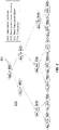
- FIG. 2 is a schematic diagram of a non-limiting exemplary topology, in this case a hierarchical topology 200 in the context of a Radio Access Network, RAN, in a cellular network.
- RAN Radio Access Network
- each node represents a resource instance
- resource type labels are indicated in upper case letters
- resource instance labels are indicated in lower case letters
- an identifier composed of a number of digits that depends on the level in the hierarchy (one digit for a BSC instance to four digits for TRX instance).
- An edge indicates a topological link between resource instances, directed from parent node to child node, indicating a hierarchical relationship in this case.
- a parent BSC can have multiple BCF as children.
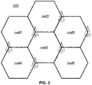
- FIG. 3 is a schematic diagram of another exemplary topology, in this case a 'flat' topology 300.
- the context is again that of cells in a cellular network - 'RC' stands for 'Radio Cell', which in the case of the present example is one resource type, and 'cellx' stands for a cell ID, with 'x' being an identifier of the cell instance.
- any two cells may either be adjacent or non-adjacent.
- the topological context between two cells (labelled 'TOPO_CONTEXT' in the present description) is set as equal to 1 in case of a geographical adjacency between the radio cells, 0 in case of no geographical adjacency.
- the topology can be expressed as follows:
- each Alarm contains a reference to a resource instance, ⁇ AT_i,RI_i:RT_i>
- the two input graphs can be connected into a common graph structure by mapping Alarm nodes in the ADS graph to resource instance nodes in the TOPO graph.
- ADS are derived from the data generated in a fixed network topology and can therefore be reused in identical network contexts, they capture more general behaviors that can be reproduced on many variants of the original topology. According to the present embodiment, such specific ADS structures are generalized in order to enable their applicability in other network contexts which preserve some topological constraints, i.e. deployments of the same network technology having similar (but not necessarily identical) topologies.
- topological context may simple be set to 'empty' .
- FIG. 4a and FIG. 4b are two examples of ADS visualizations corresponding to two different topologies.
- FIG. 4c and FIG. 4d are the respective equivalents to FIG. 4a and FIG. 4b in the frame of the non-limiting cellular network example and resource types of FIG. 2 .
- non-limiting examples of transmitter alarm types are as follows, noting that only alarm types AT1 and AT2 are used in the frame of FIG. 4c and FIG. 4d .
- the D-channel is the channel that carries control and signaling information ("D” stands for "delta”).
- FIG. 4a and FIG. 4b can be used to show the impact of the topological graph information (taken into account in step 1) on the summarization process. To illustrate this impact, only the last two steps, without the 'topological labeling' of step 1, are applied to the two graphs of FIG. 4a and FIG. 4b . This creates an abstraction from the specific network topology, where the resulting graph will merge all the ADS nodes which differ only by their resource instance but map to the same ⁇ AT_i,RT_i>.
- FIG. 4a For example, considering two alarm dependencies 401, 402 with pairwise identical alarm and resource types ⁇ AT1, r1:RT>, ⁇ AT2, r2:RT>> and ⁇ AT1, r1':RT>, ⁇ AT2, r2':RT>>, as respectively shown in FIG. 4a and FIG. 4b .
- steps 2 and 3 two nodes with a single edge ⁇ AT1, RT>, ⁇ AT2, RT>> are obtained, as illustrated in FIG. 5a.
- FIG. 5b is the equivalent of FIG. 5a in the cellular network context of FIG. 2 .
- Such an abstraction does not preserve any topological information, although it is desired to maintain information about the topological relationships between the resource instances involved in each alarm dependency at a desired level, e.g. at least at a high level. Namely, in the example above it can be important to preserve the difference between the two topological contexts; according to the tree structure of the topology graph, the resource instances on the left-side, r1 and r2, share a common parent, while the ones on the right-side share only a common grand-parent.
- This information can be encoded as an edge label, which can also be called edge type, in step 1, which would prevent from the two dependencies being merged during the summarization.
- edge label which can also be called edge type, in step 1, which would prevent from the two dependencies being merged during the summarization.
- FIG. 4a is the parent and in case of FIG. 4b is the grand-parent, grouping their alarm dependencies without considering their topological contexts would produce an abstract pattern, FIG. 5a , with two possible root-causes, which is ambiguous and not useful for other network instances with the same configuration.
- keeping the detailed topological information, including the resource instances would not permit the use of the identified alarm dependency patterns in different network instances since the involved resource instances would be different.
- the function of the topological labelling introduced at step 1 is to capture certain aspects of the topological relationships between two resource instances. Capturing this information for use in the summarization process can be performed in different ways.
- the topological context used corresponds to the longest common prefix in terms of resource instances leading from the root node to each of the resource instances, in which the involved resource instances are replaced by their types.
- the result can be used to generate the required label.
- the shortest path between two resource instances is used to model the topological context.
- the topology of FIG. 3 is an extreme case - the binary topological context mentioned above and indicative of the presence or absence of a direct neighborhood relationship can be used.
- topological context can be used to reflect the operator experience on what should be considered as a topological differentiator for the representation of reusable dependency patterns.
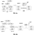
- FIG. 6a and FIG. 6b are graphs providing an example of summarization using this method; the right part of FIG. 6a shows the summarized graph SADS-1 600 which is obtained from ADS-1 400 as shown also in FIG. 4a , whereas the right part of FIG. 6b shows the summarized graph SADS-2 which is obtained from ADS-2 as shown in FIG. 4b .
- SADS-1 and SADS-2 differ in their topological context, i.e. their edge labels corresponding to the longest common prefix, RTO/RT1 and RT0, respectively, referenced 601 and 602 in the drawings.
- FIG. 6c shows the summarized graph SADS-1 when in the context of the exemplary communication network of FIG. 2 .
- FIG. 6d shows the summarized graph SADS-2 when in the context of the exemplary communication network of FIG. 2 .
- FIG. 7a provides another example of summarization - the same summarized graph SADS-3 is obtained from two equivalent ADS, which are ADS-1 and ADS-3.
- the graph ADS-1 is the same as ADS-1 in FIG. 4a .
- the second graph ADS-3 contains two alarm dependencies «AT1, rl':RT>, ⁇ AT2, r2":RT» and ⁇ AT1, rl':RT>, ⁇ AT2, r2''':RT>>, with all the edge leaves sharing the same parent.
- the summarized graph SADS-3 has an edge labelled with the shared topological context between modified alarm vertices corresponding to the longest common prefix, RTO/RT1.
- FIG. 7b shows the graphs of FIG. 7a when in the context of the exemplary communication network of FIG. 2 .
- the summarization process takes as input two graph structures: the Alarm Dependency Structure (ADS) and the Resource Topology graph (TOPO), as defined in the previous section.
- ADS Alarm Dependency Structure
- TOPO Resource Topology graph
- the ADS can be either fetched by the summarization process or the visualization module from a database or streamed to them.
- the TOPO is fetched by the summarization process or the visualization module from a database.
- a tabular representation for ADS comprising a set of dependency relationships with the following format:
- Dep(i,j) corresponds to a dependency or link ⁇ AT i , RI i : RT i >, ⁇ AT j , RI j : RT j > >.
- undirected dependencies For undirected dependencies, a pair of symmetric dependencies Dep(i,j) and Dep(j,i) is used, while for directed dependencies, only the dependency or link corresponding to this specific direction is used.
- a non-limiting example of undirected alarm dependencies comprises correlations, while a non-limiting example of directed dependencies comprises causal relationships between alarms.
- FIG. 8a represents two exemplary ADS graphs which will be considered in the detailed description of the role of module/functional blocks shown in FIG. 1 .
- FIG. 8b shows the graphs of FIG. 8a when in the context of the exemplary communication network of FIG. 2 .
- the two ADS graphs ADS-1 and ADS-4 shown on FIG. 8a can respectively be coded as follows:
- Graph visualization may optionally be performed, e.g. to allow an operator such as an expert or system administrator to carry out a first root cause analysis.
- each Alarm is associated with a resource Instance ⁇ AT i , RI i : RT i >
- the two graphs TOPO and ADS can be connected into a common graph structure by mapping Alarm nodes in ADS to resource instance nodes in TOPO, and this is the visualization shown in FIG. 8a .
- the set of alarm dependency structures in the tabular format is the input to the summarization process.
- the process comprises the steps already mentioned earlier, but applied here to the tabular data format.
- FIG. 9 is a functional block diagram similar to that of FIG. 1 in which only some modules relevant for the ADS visualization and the first step S1 have been kept and in which the first step S1 'Label ADS links' is detailed.
- ADS dependency relationship Dep ( i,j ) fetched from the ADS database or received from a stream, the topological links TOPO_links (RI i , RI j ) connecting involved resource instances RI i and RI j are retrieved from the Resource Topology Graph (TOPO) in a sub-step S1_1.
- TOPO_links in hierarchical topologies (tree structures), TOPO_links (RI i , RI j ) can correspond to the longest common prefix in terms of resource instances leading from the root node to each of the resource instances RI i and RI j .
- TOPO_links can determine the shortest path between the two resource instances RI j and RI j .
- step S1_2 can keep only the resource type of the last term of the prefix determined at sub-step S 1_1.
- ADS-1 dependencies are obtained (the last term on each line is the label):
- FIG. 10 is a functional block diagram similar to that of FIG. 1 in which only some modules relevant for the second step S2 have been kept and in which this second step S2 'Modify ADS nodes' is detailed.
- a sub-step S2_1 for each ADS dependency relationship, enriched with L ij label at previous step, the involved resource instances RI i and RI j are removed and only their types RT i and RT j are kept.
- dependencies (1) and (3) respectively dependencies (2) and (4) are identical, i.e. occur twice.
- FIG. 11 is a functional block diagram similar to that of FIG. 1 in which only some modules relevant for the third step S3 have been kept and in which this third step S3 'Merge identical ADS nodes' is detailed.
- the alarm dependency relationships in each ADS are grouped using a composed key including the alarm types AT i and AT j , the resource types RT i and RT j , and the common topological context L ij .
- SADS summarized alarm dependency structure
- Metadata is added to nodes and/or edges of the SADS.
- This metadata can result from an aggregation of metadata present in nodes and/or edges of the initial ADS graphs, or generated separately.
- the metadata can have a numerical and/or textual format or another format. It can for example reflect application specific information such as a correlation degree and/or a statistical confidence measure for edges.
- certain statistics can for example be added to grouped dependencies sharing a same key. One such statistic that may be added is for example the number of occurrences of a dependency, e.g. to weigh dependencies differently. Other statistics may comprise an average correlation degree, a corresponding statistical confidence, histograms and/or other statistical moments.
- FIG. 12 is a functional block diagram similar to that of FIG. 11 in which only some modules relevant for sub-step S3_2 have been kept and in which this sub-step S3_2 'Represent SADS graphs' is detailed.
- Summarizing the alarm dependency structures as described above comprises grouping the nodes, and consequently the edges including the topological context labels, by their resource and alarm types. This produces a new type of graph, the Summarized ADS or 'SADS' which is received as input to the graph representation module S3_2.
- FIG. 13a is a representation of the graph SADS-4 based on the summarization of the graphs ADS-1 and ADS-4 of FIG. 8a and using generic Alarm types and resource types
- FIG. 13b is a representation of SADS-4 in the context of the cellular communication network of FIG. 2 , i.e. based on the graphs illustrated in FIG. 8b .
- the occurrences of each dependency are indicated in parentheses.
- graph G at ( N at , E at ) is a graph describing the resource and alarm types dependencies SADS, where:
- the SADS in tabular format is used to derive the graph representation G at as follows.
- Reference will be made to FIG. 13c to 13i which represent the graphs at different stages of the representation construction.
- the graphs of FIG. 13c to 13i are only represented in their generalized format, not in the context of the communication network of FIG. 2 .
- processing the next summarized dependency relationship of SADS-4 DepLMM (2,1) will transform the directed edge ⁇ RT, AT 1 >, RT 1, ⁇ RT,AT 2 >> into a non-directed edge (symmetric summarized relationship), as shown in FIG. 13f .
- step 2a Processing the next summarized dependency relationship of SADS-4 DepLMM(1,3) and applying step 2a will result in no change compared to the previous graph of FIG. 13f , since the left-hand node of the expression already exists.
- Applying step 2b adds a third node corresponding to the right-hand node of the expression as illustrated by FIG. 13g and lastly applying step 2c adds an edge associated with the topological information 'RT0' as illustrated by FIG. 13h .
- the result of applying the summarization to a set of ADS is a set of unique summarized graphs (outputs of S3_2 on FIG. 12 ) which represent reusable alarm propagation scenarios and which can be instantiated in multiple similar (but not exactly the same, non-isomorphic) topological contexts.
- the summarization of graphs is a normal form representation which enables identifying the same alarm propagation patterns in different datasets.
- the summarized ADS may be visualized as shown in FIG. 14a (and FIG. 14b when considering the context of the network of FIG. 2 ) using the visualization module 106 as shown e.g. in FIG. 1 and FIG. 12 , so as to be examined by an expert and/or system administrator.
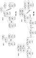
- FIG. 14 both the original ADS (here ADS-1 and ADS-4) and the summarized ADS (here SADS-4) are shown jointly, allowing to navigate back and forth between the two. This gives the possibility of viewing the ADS that were summarized into one or more SADS and vice-versa.
- FIG. 15 is a functional block diagram of a non-limiting embodiment of a classifier training architecture
- FIG. 16 is a functional block diagram of a non-limiting embodiment of an architecture using a previously trained classifier to classify new alarm logs. While the functional blocks of each architecture are presented separately, the functions corresponding to an architecture may be carried out by a single device or shared among several devices. Also, one or more functions of the classifier training architecture and functions of the log classification architecture may be combined in a same device.
- the classifier training architecture comprises an event dependency source 1501 - this may be an interface receiving a data stream, or a storage medium comprising a set of data.
- the source provides a set of labelled alarm logs where the label indicates the class to which the log belongs e.g. "normal behavior" or the type of fault represented by the alarms.
- a graph dependency builder 1502 then creates an ADS graph, associated with its class, and that will feed the graph summarizer 103.
- the graph summarizer will produce a summarized ADS, SADS, as previously explained, again associated with a class, the resulting summarized alarm dependencies serving as inputs to the classifier training, at module 1503.
- SADS summarized ADS
- an ADS graph may comprise more than a single sub-graph, i.e. a plurality of disconnected sub-graphs.
- a resulting SADS may comprise one or more sub-graphs.
- one or more alarm logs may be used to generate a single ADS.
- a single alarm log is used to generate an ADS.
- Classification algorithms per se will not be detailed here - some examples of applicable classifiers include various ML models such as Deep Neural Nets, Decision Trees, Random Forests, or Bayesian classifiers. Trained classifier models are stored in a classifier model storage module for later use.
- the classifier assigns each unlabeled log to the most appropriate class according to the model built using the samples labelled with a class.
- the architecture of FIG. 16 comprises an event dependency source 1601, generating event or alarm logs for which a class is to be determined.
- a graph builder 1602 uses the logs to build an alarm dependency graph ADS, which is then summarized by summarizer module 1603.
- Summarizer module 1603 is similar to the summarizer module 103 described above.
- the output SADS of summarizer 1603 is fed to a classifier 1604, using which applies models resulting from prior training and available from storage module 1605.
- the resulting class is then provided to a user, e.g.
- the output the summarization process can be used as input of a classifier because it captures invariant patterns of event dependencies.
- the same phenomenon appearing in two different but similar network contexts having different instance alarm dependency graphs
- this similarity will be used by the classifier to assign the two summarized alarm dependency graphs to a same class.
- the methods described herein enables obtaining normalized - and hence comparable - representations through generalization of event logs collected from different application contexts and different instantiations.
- FIG. 17 is a block diagram of a device 1700 that, according to an exemplary embodiment, can be used to implement any one or more of the functional blocks presented in FIG.1 , FIG. 9 to 12 , FIG. 15 and/or FIG. 16 and to carry out partially or fully the methods described herein.
- the device 1700 comprises a printed circuit board 1701 on which a communication bus 1702 connects a processor 1703, a random access memory 1704, a storage medium 1711, an interface 1705 for connecting a display 1706, a series of connectors 1707 for connecting user interface devices or modules such as a mouse or trackpad 1708 and a keyboard 1709, a wireless network interface 1710 and a wired network interface 1712.
- the device may implement only part of the above.
- Certain modules of the device 1700 may be internal or connected externally, in which case they do not necessarily form integral part of the device itself.
- display 1706 may be a display that is connected to a device only under specific circumstances, or the device may be controlled through another device with a display, i.e. no specific display 1706 and interface 1705 are then required for device 1700.
- Storage medium 1711 contains software code which, when executed by processor 1703, causes the device to carry out the methods described herein.
- the device according to UA1 further configured to cause the dependencies of said first alarm dependency structure to be obtained from an analysis of correlations and/or causal relationships of events in an alarm log.
- UA3 The device according to UA1 or UA2, wherein the topology comprises resources instances of said network and physical and/or virtual and/or logical connections between said network resources.
- topological information comprises, for hierarchical network topologies, one of:
- topological information comprises, for flat network topologies, the shortest common resource type sequence between two resource instances of alarms linked by a dependency.
- the device further configured to cause application of said assigning, replacing and merging to a plurality of alarm dependency structures (400) to obtain a single summarized alarm dependency structure (600).
- the device further configured to cause visualization of said alarm dependency structure in the form of a graph in which dependencies are shown as edges linking vertices, wherein a vertex representation comprises a resource instance and a corresponding resource type, and an alarm type for resource instances which generated an alarm.
- the device further configured to cause visualization said of summarized alarm dependency structure in the form of a graph in which dependencies are shown as edges linking vertices, wherein dependencies are represented with their associated topology information and wherein a vertex representation comprises a resource type and an alarm type.
- the device further configured to cause aggregation of metadata associated with at least part of a plurality of dependencies of said alarm dependency structure being merged into one dependency, to form metadata of the one dependency resulting from the merging.
- UA12 The device according to example UA11, further configured to cause said classifier means to use a classifier model obtained from prior training based on at least one summarized alarm dependency structure and an associated known network state class.
Landscapes
- Engineering & Computer Science (AREA)
- Computer Networks & Wireless Communication (AREA)
- Signal Processing (AREA)
- Human Computer Interaction (AREA)
- Physics & Mathematics (AREA)
- Algebra (AREA)
- General Physics & Mathematics (AREA)
- Mathematical Analysis (AREA)
- Mathematical Optimization (AREA)
- Mathematical Physics (AREA)
- Probability & Statistics with Applications (AREA)
- Pure & Applied Mathematics (AREA)
- Artificial Intelligence (AREA)
- Computer Vision & Pattern Recognition (AREA)
- Databases & Information Systems (AREA)
- Evolutionary Computation (AREA)
- Medical Informatics (AREA)
- Software Systems (AREA)
- Data Exchanges In Wide-Area Networks (AREA)
Abstract
Description
- The present application concerns methods and devices for network monitoring, in particular for detecting network states such as faulty behavior in the context of communication networks.
- Complex networked systems such as modern telecommunication networks generate huge amounts of alarm logs and notifications, in which it is extremely challenging to distinguish real fault symptoms from noisy alarms. Exemplary networks combine for example 5G, IoT and Cloud technologies. Human operators striving to identify fault situations and localize the root causes may be overwhelmed with high volumes of data and may fail to provide timely explanations. There is a need for powerful tools for automated fault identification and root cause analysis (RCA).
- An embodiment concerns a device for providing training data to a classifier for monitoring a network of resource instances wherein resource instances are organized according to a topology, resource instances having respective resource types defining a resource category, at least part of the resource instances generating alarms, alarms having respective alarm types defining alarm categories, the device comprising:
- means for obtaining an alarm dependency structure, ADS, comprising dependencies between alarms, wherein an alarm of said ADS is associated with the resource instance which generated it and with its alarm type, said ADS being associated with a network state class;
- means for assigning topological information to a given dependency, said topological information being function of a link, within the topology, of the resource instances associated with the alarms linked by said given dependency;
- means for replacing respective resource instances associated with alarms by their respective resource types;
- means for merging a first pair of resource types and associated alarm types linked by a first dependency and a second pair of resource types and associated alarm types linked by a second dependency if (a) a first resource type and its associated alarm type of the first pair are identical to a first resource type and associated alarm type of the second pair and (b) a second resource type and its associated alarm type of the first pair are identical to a second resource type and associated alarm of the second pair and (c) if the topological information of the first dependency and of the second dependency is identical;
- means for providing classifier training data comprising said network state class and a summarized alarm dependency structure, SADS, resulting from said assigning, replacing and merging.
- According to an embodiment, the means for obtaining a first alarm dependency structure are further configured to obtain the dependencies of said first alarm dependency structure are from an analysis of correlations and/or causal relationships of events in an alarm log.
- According to an embodiment, the topology comprises resources instances of said network and physical and/or virtual and/or logical connections between said network resources.
- According to an embodiment, the topological information comprises, for hierarchical network topologies, one of:
- the resource type sequence of the longest common resource instance sequence obtained by matching resource instance sequences leading from a root node of said hierarchical topology to the resource instances of alarms linked by a dependency; or
- the last common term closest to the resource instances of the resource type sequence of the longest common resource instance sequence obtained by matching resource instance sequences leading from a root node of said hierarchical topology to the resource instances of alarms linked by a dependency, in case said last term of the longest common resource type sequence allows to deterministically determine said type sequence from the root.
- According to an embodiment, the topological information comprises, for flat network topologies, the shortest common resource type sequence between two resource instances of alarms linked by a dependency.
- According to an embodiment, said assigning, replacing and merging means are further configured to process a plurality of alarm dependency structures to obtain a single summarized alarm dependency structure.
- According to an embodiment, said class is one among one or more normal behavior states and one or more faulty behavior states.
- According to an embodiment, said training means are further configured to train a classifier with a plurality of summarized alarm dependency structures associated with at least one class.
- According to an embodiment, the device further comprises
- means for visualizing said alarm dependency structure in the form of a graph in which dependencies are shown as edges linking vertices, wherein a vertex representation comprises a resource instance and a corresponding resource type, and an alarm type for resource instances which generated an alarm; and
- means for visualizing said summarized alarm dependency structure in the form of a graph in which dependencies are shown as edges linking vertices, wherein dependencies are represented with their associated topology information and wherein a vertex representation comprises a resource type and an alarm type.
- According to an embodiment, said means for merging are further configured to aggregate metadata associated with at least part of a plurality of dependencies of said alarm dependency structure being merged into one dependency, to form metadata of the one dependency resulting from the merging.
- An embodiment concerns a device for monitoring a network of resource instances wherein resource instances are organized according to a topology, resource instances having respective resource types defining a resource category, at least part of the resource instances generating alarms, alarms having respective alarm types defining alarm categories, comprising:
- means for obtaining a second alarm dependency structure, ADS, for which a network state class is to be determined, said ADS comprising dependencies between alarms, wherein an alarm of said ADS is associated with the resource instance which generated it and with its alarm type;
- means for assigning topological information to a given dependency, said topological information being function of a link, within the topology, of the resource instances associated with the alarms linked by said given dependency;
- means for replacing respective resource instances associated with alarms by their respective resource types;
- means for merging a first pair of resource types and associated alarm types linked by a first dependency and a second pair of resource types and associated alarm types linked by a second dependency if (a) a first resource type and its associated alarm type of the first pair are identical to a first resource type and associated alarm type of the second pair and (b) a second resource type and its associated alarm type of the first pair are identical to a second resource type and associated alarm of the second pair and (c) if the topological information of the first dependency and of the second dependency is identical, and for providing a summarized alarm dependency structure, SADS, resulting from said assigning, replacing and merging, to classifier means;
- classifier means for providing a network state class as a function of said SADS.
- According to an embodiment, said classifier means use a classifier model obtained from prior training based on at least one summarized alarm dependency structure and an associated known network state class.
- An embodiment concerns a method for providing training data to a classifier for monitoring a network of resource instances wherein resource instances are organized according to a topology, resource instances having respective resource types defining a resource category, at least part of the resource instances generating alarms, alarms having respective alarm types defining alarm categories, comprising:
- obtaining an alarm dependency structure, ADS, comprising dependencies between alarms, wherein an alarm of said ADS is associated with the resource instance which generated it and with its alarm type, said ADS being associated with a network state class;
- assigning topological information to a given dependency, said topological information being function of a link, within the topology, of the resource instances associated with the alarms linked by said given dependency;
- replacing respective resource instances associated with alarms by their respective resource types;
- merging a first pair of resource types and associated alarm types linked by a first dependency and a second pair of resource types and associated alarm types linked by a second dependency if (a) a first resource type and its associated alarm type of the first pair are identical to a first resource type and associated alarm type of the second pair and (b) a second resource type and its associated alarm type of the first pair are identical to a second resource type and associated alarm of the second pair and (c) if the topological information of the first dependency and of the second dependency is identical;
- providing said network state class and a summarized alarm dependency structure, SADS, resulting from said assigning, replacing and merging, for classifier training.
- An embodiment concerns method for monitoring a network of resource instances wherein resource instances are organized according to a topology, resource instances having respective resource types defining a resource category, at least part of the resource instances generating alarms, alarms having respective alarm types defining alarm categories, comprising:
- obtaining an alarm dependency structure, ADS, for which a network state class is to be determined, said ADS comprising dependencies between alarms, wherein an alarm of said ADS is associated with the resource instance which generated it and with its alarm type;
- assigning topological information to a given dependency, said topological information being function of a link, within the topology, of the resource instances associated with the alarms linked by said given dependency;
- replacing respective resource instances associated with alarms by their respective resource types;
- merging a first pair of resource types and associated alarm types linked by a first dependency and a second pair of resource types and associated alarm types linked by a second dependency if (a) a first resource type and its associated alarm type of the first pair are identical to a first resource type and associated alarm type of the second pair and (b) a second resource type and its associated alarm type of the first pair are identical to a second resource type and associated alarm of the second pair and (c) if the topological information of the first dependency and of the second dependency is identical;
- providing a summarized alarm dependency structure, SADS, resulting from said assigning, replacing and merging, to a classifier;
- obtaining a network state class as a function of said SADS.
- According to an embodiment, said classifier means use a classifier model obtained from prior training based on at least one summarized alarm dependency structure and an associated known network state class.
- Example embodiments will be more fully understood from the detailed description given herein below and the accompanying drawings, which are given by way of illustration only.
-
FIG. 1 is a block diagram of high-level functional blocks for the summarization of alarm dependency structures according to an embodiment; -
FIG. 2 is a diagram of a non-limiting example of a hierarchical topology of a radio access network, RAN, architecture in a cellular network context; -
FIG. 3 is a diagram of a non-limiting example of a flat topology of cells in the context of a cellular network; -
FIG. 4a and FIG. 4b are respective visualizations of two Alarm Dependency Structure, ADS, graphs with different topological contexts, according to a non-limiting embodiment; -
FIG. 4c and FIG. 4d are respective visualizations of the graphs ofFIG. 4a and FIG. 4b in the topological context of the cellular network illustrated byFIG. 2 ; -
FIG. 5a is a visualization of the Summarized Alarm Dependency Structure, SADS, ofFIG. 4a and FIG. 4b when topological information is disregarded in the summarization process; -
FIG. 5b is a visualization of the Summarized Alarm Dependency Structure, SADS, ofFIG. 4c and FIG. 4d when topological information is disregarded in the summarization process; -
FIG. 6a and FIG. 6b are respective visualizations of the summarizations resulting from the graphs ofFIG. 4a and FIG. 4b , respectively, when topological information is taken into account according to a non-limiting embodiment; -
FIG. 6c and FIG. 6d are respective visualizations of the summarizations resulting from the graphs ofFIG. 4c and FIG. 4d in the topological context of the cellular network illustrated byFIG. 2 ; -
FIG. 7a is a visualization of two ADS graphs and the resulting SADS identical for both ADS according to a non-limiting embodiment,FIG.7b being the counterpart toFIG. 7a in the context of the network ofFIG. 2 ; -
FIG. 8a is a visualization of two ADS graphs to be combined into a single SADS,FIG.8b being the counterpart toFIG. 8a in the context of the network ofFIG. 2 ; -
FIG. 9 is a functional block diagram detailing a first operation within an ADS summarization functional block ofFIG. 1 according to a non-limiting embodiment; -
FIG. 10 is a functional block diagram detailing a second operation within an ADS summarization functional block ofFIG. 1 according to a non-limiting embodiment; -
FIG. 11 is a functional block diagram detailing a third operation within an ADS summarization functional block ofFIG. 1 according to a non-limiting embodiment; -
FIG. 12 is a functional block diagram detailing sub-steps of the third operation of an ADS summarization functional block ofFIG. 1 according to a non-limiting embodiment; -
FIG. 13a is a visualization of a SADS resulting from the summarization of the two ADS graphs ofFIG. 8a ,FIG. 13b being the counterpart toFIG. 13a in the context of the network ofFIG. 2 ; -
FIG. 13c to FIG. 13i are visualizations of the SADS graph ofFIG. 13a according to the method shown in the sub-steps ofFIG. 12 based on a table format for graph representation according to a non-limiting embodiment; -
FIG. 14a is a visualization of the summarization of the ADS graphs ofFIG. 8a resulting in the SADS graph ofFIG. 13a , whereasFIG. 14b is the counterpart ofFIG. 13b ; -
FIG. 15 is a functional block diagram of a non-limiting embodiment of a classifier training architecture; -
FIG. 16 is a functional block diagram of a non-limiting embodiment of an architecture using a previously trained classifier to classify alarm logs; -
FIG. 17 is a block diagram of a processing device for carrying out part or all of the methods described herein. - It should be noted that these figures are intended to illustrate the general characteristics of methods, structure and/or materials utilized in certain example embodiments and to supplement the written description provided below. These drawings are not, however, to scale and may not precisely reflect the precise structural or performance characteristics of any given embodiment, and should not be interpreted as defining or limiting the range of values or properties encompassed by example embodiments. The use of similar or identical reference numbers in the various drawings is intended to indicate the presence of a similar or identical element or feature.
- Various exemplary embodiments will now be described more fully with reference to the accompanying drawings. However, specific structural and functional details disclosed herein are merely representative for purposes of describing example embodiments. The exemplary embodiments may be embodied in many alternate forms and should not be construed as limited to only the embodiments set forth herein. It should be understood that there is no intent to limit example embodiments to the particular forms disclosed.
- It should be appreciated by those skilled in the art that any functions, engines, block diagrams, flow diagrams, state transition diagrams and / or flowcharts herein represent conceptual views of illustrative circuitry embodying the principles of the invention. Similarly, it will be appreciated that any flow charts, flow diagrams, state transition diagrams, pseudo code, and the like represent various processes which may be substantially represented in computer readable medium and so executed by a computer or processing apparatus, whether or not such computer or processor is explicitly shown.
- Each described function, engine, block, step can be implemented in hardware, software, firmware, middleware, microcode, or any suitable combination thereof. If implemented in software, the functions, engines, blocks of the block diagrams and/or flowchart illustrations can be implemented by computer program instructions / software code, which may be stored or transmitted over a computer-readable medium, or loaded onto a general purpose computer, special purpose computer or other programmable processing apparatus and / or system to produce a machine, such that the computer program instructions or software code which execute on the computer or other programmable processing apparatus, create the means for implementing the functions described herein.
- In the present description, functional blocks denoted as "means configured to perform ..." (a certain function) shall be understood as functional blocks comprising circuitry that is adapted for performing or configured to perform a certain function. A means being configured to perform a certain function does, hence, not imply that such means necessarily is performing said function (at a given time instant). Moreover, any entity described herein as "means", may correspond to or be implemented as "one or more modules", "one or more devices", "one or more units", etc. When provided by a processor, the functions may be provided by a single dedicated processor, by a single shared processor, or by a plurality of individual processors, some of which may be shared. Moreover, explicit use of the term "processor" or "controller" should not be construed to refer exclusively to hardware capable of executing software, and may implicitly include, without limitation, digital signal processor (DSP) hardware, network processor, application specific integrated circuit (ASIC), field programmable gate array (FPGA), read only memory (ROM) for storing software, random access memory (RAM), and non-volatile storage. Other hardware, conventional or custom, may also be included. Their function may be carried out through the operation of program logic, through dedicated logic, through the interaction of program control and dedicated logic, or even manually, the particular technique being selectable by the implementer as more specifically understood from the context.
- Although a flow chart may describe the operations as a sequential process, many of the operations may be performed in parallel, concurrently or simultaneously. In addition, the order of the operations may be re-arranged. A process may be terminated when its operations are completed, but may also have additional steps not included in the figure. A process may correspond to a method, function, procedure, subroutine, subprogram, etc. When a process corresponds to a function, its termination may correspond to a return of the function to the calling function or the main function.
- As disclosed herein, the term "storage medium", "computer readable storage medium" or "non-transitory computer readable storage medium" may be any physical media that can be read, written or more generally accessed by a computer / a processing device. Examples of computer storage media include, but are not limited to, a flash drive or other flash memory devices (e.g. memory keys, memory sticks, USB key drive), CD-ROM or other optical storage, DVD, magnetic disk storage or other magnetic storage devices, solid state memory, memory chip, RAM, ROM, EEPROM, smart cards, a relational database management system, a traditional database, or any other suitable medium that can be used to carry or store program code in the form of instructions or data structures which can be read by a computer processor. Also, various forms of computer-readable medium may be used to transmit or carry instructions to a computer, including a router, gateway, server, or other transmission device, wired (coaxial cable, fiber, twisted pair, DSL cable) or wireless (infrared, radio, cellular, microwave). The instructions may include code from any computer-programming language, including, but not limited to, assembly, C, C++, Basic, SQL, MySQL, HTML, PHP, Python, Java, Javascript, etc. Embodiments of a computer-readable medium include, but are not limited to, both computer storage media and communication media including any medium that facilitates transfer of a computer program from one place to another. Specifically, program instructions or computer readable program code to perform embodiments described herein may be stored, temporarily or permanently, in whole or in part, on a non-transitory computer readable medium of a local or remote storage device including one or more storage media.
- Furthermore, example embodiments may be implemented by hardware, software, firmware, middleware, microcode, hardware description languages, or any combination thereof. When implemented in software, firmware, middleware or microcode, the program code or code segments to perform the necessary tasks may be stored in a machine or computer readable medium such as a computer readable storage medium. When implemented in software, a processor or processors will perform the necessary tasks. For example, as mentioned above, according to one or more example embodiments, at least one memory may include or store computer program code, and the at least one memory and the computer program code may be configured to, with at least one processor, cause a network element or network device to perform the necessary tasks. Additionally, the processor, memory and example algorithms, encoded as computer program code, serve as means for providing or causing performance of operations discussed herein.
- A code segment of computer program code may represent a procedure, function, subprogram, program, routine, subroutine, module, software package, class, or any combination of instructions, data structures or program statements. A code segment may be coupled to another code segment or a hardware circuit by passing and/or receiving information, data, arguments, parameters or memory contents. Information, arguments, parameters, data, etc. may be passed, forwarded, or transmitted via any suitable technique including memory sharing, message passing, token passing, network transmission, etc.
- The terms "including" and/or "having," as used herein, are defined as comprising (i.e., open language). The term "coupled," as used herein, is defined as connected, although not necessarily directly, and not necessarily mechanically. Terminology derived from the word "indicating" (e.g., "indicates" and "indication") is intended to encompass all the various techniques available for communicating or referencing the object/information being indicated. Some, but not all, examples of techniques available for communicating or referencing the object/information being indicated include the conveyance of the object/information being indicated, the conveyance of an identifier of the object/information being indicated, the conveyance of information used to generate the object/information being indicated, the conveyance of some part or portion of the object/information being indicated, the conveyance of some derivation of the object/information being indicated, and the conveyance of some symbol representing the object/information being indicated.
- Although the terms first, second, etc. may be used herein to describe various elements, these elements should not be limited by these terms. These terms are only used to distinguish one element from another. For example, a first element could be termed a second element, and similarly, a second element could be termed a first element, without departing from the scope of this disclosure. As used herein, the term "and/or," includes any and all combinations of one or more of the associated listed items.
- According to example embodiments, network elements, network devices, data servers, network resource controllers, network apparatuses, clients, routers, gateways, network nodes, computers, cloud-based servers, web servers, application servers, proxies or proxy servers, or the like, may be (or include) hardware, firmware, hardware executing software or any combination thereof. Such hardware may include processing or control circuitry such as, but not limited to, one or more processors, one or more CPUs, one or more integrated circuits one or more controllers, one or more ALUs, one or more DSPs, one or more microcomputers, one or more FPGAs, one or more SoCs, one or more PLUs, one or more microprocessors, one or more ASICs, or any other device or devices capable of responding to and executing instructions in a defined manner.
- As used in this application, the term "circuitry" may refer to one or more or all of the following:
- (a) hardware-only circuit implementations (such as implementations in only analog and/or digital circuitry) and
- (b) combinations of hardware circuits and software, such as (as applicable):
- (i) a combination of analog and/or digital hardware circuit(s) with software/firmware and
- (ii) any portions of hardware processor(s) with software (including digital signal processor(s)), software, and memory(ies) that work together to cause an apparatus, such as a mobile phone or server, to perform various functions) and
- (c) hardware circuit(s) and or processor(s), such as a microprocessor(s) or a portion of a microprocessor(s), that requires software (e.g., firmware) for operation, but the software may not be present when it is not needed for operation.
- This definition of circuitry applies to all uses of this term in this application, including in any claims. As a further example, as used in this application, the term circuitry also covers an implementation of merely a hardware circuit or processor (or multiple processors) or portion of a hardware circuit or processor and its (or their) accompanying software and/or firmware. The term circuitry also covers, for example and if applicable to the particular claim element, a baseband integrated circuit or processor integrated circuit for a mobile device or a similar integrated circuit in server, a cellular network device, or other computing or network device.
- A set of interconnected entities generates a flow of events. This can be the case for managed objects in networks, such as telecommunication networks. Fault situations may need to be identified and the root causes localized. Events can for example comprise alarms and/or notifications that reflect local state changes at each network object. Other types of events may also be taken into consideration. Events such as alarms and notifications can be present during the normal operation of the network, they can also reflect the occurrence of important faults in the underlying hardware or software components. In what follows, the terms event and alarm are used interchangeably.
- According to an embodiment, reusable characteristics of event series that can help automate fault identification and root cause localization are defined. More specifically, given a set of classified or categorized situations, reusable representations of the corresponding event series are extracted. These representations are reproduced in other network deployments of the same type.
- According to an embodiment, summarized alarm dependency structures are generated, these structures representing patterns of dependencies that characterize network situations of interest such as different fault types or normal behaviors that manifest themselves through generation of alarms and notifications. The summarized structures preserve some information on the topological context. This enables creation of abstractions which are applicable to different network instances with topology variations. This feature is particularly relevant to 5G radio access and core networks, given the virtualization and adaptability features; 5G networks can be dynamically deployed, reconfigured, or scaled up/down. In such networks, the summarized alarm dependency structures as detailed below can be transferred to alternative deployments or modified topologies.
- Several network management and supervision related products such as NetAct, NetCool, UFM (Unified Fault Management) / PTF, can benefit from the capability provided by the current invention to detect, and classify fault situations, to help in root causes identification and to represent the topology in a reusable summarized form.
- In the following description, the notations 'X_y' and 'Xy' are equivalent.
- In what follows, the following terminology used:
- A managed object is an abstract representation of network resources, covering their physical or logical entities, hardware or software components. In a telecommunications environment, a managed object corresponds to a resource within this telecommunications environment that may be managed through the use of operation, administration, maintenance, and provisioning protocols. In the present description, managed objects are referred to as 'Resource Instances', RI.
- 'Resource Types', RT, represent categories of network resources, e.g. a base station, a multiradio base transceiver station (MRBTS), LTE eNodeB Base Transceiver Station (LNBTS), a controller, a cell, radio transmitter, software components, other managed object types that may generate events... The notation 'RI:RT' is used to indicate that a resource instance RI is of type RT.
- 'Alarm' (or 'Notification', or 'Event') is an event associated with a resource instance and which is raised when the latter enters some state of interest, e.g. encounters performance issues, or fails to deliver an expected service. Alarms do not necessarily characterize a fault, but as indicated above may qualify any state of interest. Alarm is defined as a tuple <Alarm Type, Resource Instance:RT>, or <AT, RI:RT>. An Alarm can have multiple occurrences (at different times) at the same resource instance.
- 'Alarm log' is a list of Alarm occurrences at possibly different resource instances.
- 'Alarm Type', AT, allows network administrator to group alarms into categories according to their common semantics or the function used to generate them, e.g. Excessive CPU Usage, Loss of Signal, Channel Failure Rate Above Threshold, etc.
- 'Resource Topology', TOPO, is a graph composed of resource instances as nodes, and their (topological) connections as edges.
- A non-limiting example of a log file is provided below. A log file can comprise multiple lines of the following format:
ST;ET;RI;RT;AT where: - ST: Start Timestamp of the alarm
- ET: End Timestamp of the alarm
- RI: Resource Instance on which the alarm occurred
- RT: Resource Type
- AT: Alarm Type
-
- 2021/03/15 00:13:24;2021/01/13 00:35:11;trx_1112;TRX;AT2
- 2021/03/15 00:22:05;2021/01/13 00:47:54;trx_1111;TRX;AT1
- 2021/03/15 01:05:18;2021/01/13 01:17:33;trx_1111;TRX;AT1
- 2021/03/15 01:09:37;2021/01/13 01:24:39;trx_1112;TRX;AT2
- According to the present embodiment, identification of states in event logs, such as fault identification in alarm logs is based on the summarization of dependency structures.
FIG. 1 is a high level functional diagram of the functional blocks used in the summarization. - According to the present embodiment, the input to the summarization comprises two graph structures:
- An Alarm Dependency Structure, ADS, the source of which is referenced 101 in
FIG. 1 , which is based on a set of dependencies such as correlations or causal relationships between Alarms. Such dependencies are typically derived from data based on the analysis of co-occurrences or temporal orderings of events.
ADS is a graph defined by alarms <Alarm Type, Resource Instance:RT>, as vertices and alarm dependencies as edges, <<AT_i, RI_i:RT_i>,<AT_j, RI_j:RTj>> - these edges are represented as thick lines in the drawings.
Non-limiting examples of methods to determine dependencies comprise :- (a) use of a Jaccard coefficient to identify alarm correlations, by measuring the proportion of time during which two alarms are active with respect to the time during which at least one of them is active (https://en.wikipedia.org/wiki/Jaccard_index); and
- (b) use of Granger Causality to determine if one event series is useful to forecast another (https://en.wikipedia.org/wiki/Granger_causality).
- A Resource Topology graph, TOPO, the source of which is referenced 102 in
FIG. 1 , as defined above; it contains resource instance dependencies which can be retrieved 1/ from the hierarchy of managed objects (e.g. from resource naming schemes), 2/ from object connectivity data in configuration or provisioning tools, 3/ from other sources describing network device architecture and implementation. In other words, the resource topology graph reflects physical, virtual and/or logical connectivity between the network resources and describes the specifics of a given (sub-)network deployment.
TOPO is a graph defined by resource instances <Resource Instance:RT> as vertices and topological relationships <<RI_i:RT_i>,<RI_j:RTj>> of the resource instances as edges - these edges are represented by thin lines in the drawings. - The two dependency graphs ADS and TOPO are fed to a
summarization module 103, which outputs a 'summarized ADS' graph, SADS, 104. The summarization module carries out threemain operations S 1, S2 and S3 inFIG. 1 and which will be described in detail below. Visualization of graphs may be performed,e.g. module 105 for visualizing the ADS and its topological context, ormodule 106 for visualizing the SADS. - The summarization process may use topological graphs representing very different topologies. Two examples are provided in
FIG. 2 andFIG. 3 . -
FIG. 2 is a schematic diagram of a non-limiting exemplary topology, in this case ahierarchical topology 200 in the context of a Radio Access Network, RAN, in a cellular network. This example will be referred to at numerous occasions in the detailed explanations of the summarization process to exemplify a possible, but non-limiting, real-world implementation. - The following resource types RT are used in the example of
FIG. 2 , in an order from the highest hierarchical component to the lowest hierarchical component: - BSC: Base Station Controller
- BCF: Base Station Control Function
- BTS: Base Transceiver Station
- TRX: Transceiver
- In
FIG. 2 , each node represents a resource instance, resource type labels are indicated in upper case letters, while resource instance labels are indicated in lower case letters, followed by an identifier composed of a number of digits that depends on the level in the hierarchy (one digit for a BSC instance to four digits for TRX instance). An edge indicates a topological link between resource instances, directed from parent node to child node, indicating a hierarchical relationship in this case. E.g. a parent BSC can have multiple BCF as children. -
FIG. 3 is a schematic diagram of another exemplary topology, in this case a 'flat'topology 300. The context is again that of cells in a cellular network - 'RC' stands for 'Radio Cell', which in the case of the present example is one resource type, and 'cellx' stands for a cell ID, with 'x' being an identifier of the cell instance. In this example, any two cells may either be adjacent or non-adjacent. As a non-limiting example, the topological context between two cells (labelled 'TOPO_CONTEXT' in the present description) is set as equal to 1 in case of a geographical adjacency between the radio cells, 0 in case of no geographical adjacency. For the example ofFIG. 3 , the topology can be expressed as follows: - TOPO_CONTEXT(cell1:RC,cell2:RC) = 1
- TOPO_CONTEXT(cell1:RC,cell3:RC) = 1
- TOPO_CONTEXT(cell1:RC,cell5:RC) = 0
- Given that each Alarm contains a reference to a resource instance, <AT_i,RI_i:RT_i>, the two input graphs can be connected into a common graph structure by mapping Alarm nodes in the ADS graph to resource instance nodes in the TOPO graph.
- While ADS are derived from the data generated in a fixed network topology and can therefore be reused in identical network contexts, they capture more general behaviors that can be reproduced on many variants of the original topology. According to the present embodiment, such specific ADS structures are generalized in order to enable their applicability in other network contexts which preserve some topological constraints, i.e. deployments of the same network technology having similar (but not necessarily identical) topologies.
- An exemplary embodiment of the ADS summarization module will now be described. According to this embodiment, the following steps, or operations, are performed:
- Step 1 ('S1'): label (i.e. associate / map) each alarm dependency <<AT_i, RI_i:RT_i>,<AT_j, RI_j:RT_j>> by (with / to) the topological context that relates the two resource instances present in its vertices:
Label(<<AT_i, RI_i:RT_i>,<AT_j ,RI_j:RT_j>>) = TOPO_CONTEXT(RI_i:RT_i,
RI_j:RT_j), - Step 2 ('S2'): modify each alarm vertex by replacing the resource instance by its type:
<AT_i, RI_i:RT_i> => <AT_i, RT_i>, - Step 3 ('S3'): merge the resulting identical vertices and edges, considering the labels (i.e. labels of two edges need to be identical for a merge to be possible).
- Note that a given topology may not always enable deriving a topological context for each dependency - in this case, the topological context may simple be set to 'empty' .
-
FIG. 4a and FIG. 4b are two examples of ADS visualizations corresponding to two different topologies.FIG. 4c and FIG. 4d are the respective equivalents toFIG. 4a and FIG. 4b in the frame of the non-limiting cellular network example and resource types ofFIG. 2 . In the context ofFIG. 4c and FIG. 4d and also some of the subsequent drawings, non-limiting examples of transmitter alarm types are as follows, noting that only alarm types AT1 and AT2 are used in the frame ofFIG. 4c and FIG. 4d . - AT1: "D-CHANNEL FAILURE"
- AT2: "TRANSMITTER (TRX) FAULTY"
- AT3: "TRANSMITTER (TRX) RESTARTED"
- AT4: "EXCESSIVE TRANSMISSION CHANNEL (TCH) INTERFERENCE"
- In the above example, the D-channel is the channel that carries control and signaling information ("D" stands for "delta").
-
FIG. 4a and FIG. 4b can be used to show the impact of the topological graph information (taken into account in step 1) on the summarization process. To illustrate this impact, only the last two steps, without the 'topological labeling' ofstep 1, are applied to the two graphs ofFIG. 4a and FIG. 4b . This creates an abstraction from the specific network topology, where the resulting graph will merge all the ADS nodes which differ only by their resource instance but map to the same <AT_i,RT_i>. For example, considering twoalarm dependencies FIG. 4a and FIG. 4b . By applyingsteps FIG. 5a. FIG. 5b is the equivalent ofFIG. 5a in the cellular network context ofFIG. 2 . - Such an abstraction, however, does not preserve any topological information, although it is desired to maintain information about the topological relationships between the resource instances involved in each alarm dependency at a desired level, e.g. at least at a high level. Namely, in the example above it can be important to preserve the difference between the two topological contexts; according to the tree structure of the topology graph, the resource instances on the left-side, r1 and r2, share a common parent, while the ones on the right-side share only a common grand-parent. This information can be encoded as an edge label, which can also be called edge type, in
step 1, which would prevent from the two dependencies being merged during the summarization. As an example, if the root-cause in case ofFIG. 4a is the parent and in case ofFIG. 4b is the grand-parent, grouping their alarm dependencies without considering their topological contexts would produce an abstract pattern,FIG. 5a , with two possible root-causes, which is ambiguous and not useful for other network instances with the same configuration. On the other hand, keeping the detailed topological information, including the resource instances, would not permit the use of the identified alarm dependency patterns in different network instances since the involved resource instances would be different. - The function of the topological labelling introduced at
step 1 is to capture certain aspects of the topological relationships between two resource instances. Capturing this information for use in the summarization process can be performed in different ways. - According to a first non-limiting example, which can be used in hierarchical topologies (tree structures), the topological context used corresponds to the longest common prefix in terms of resource instances leading from the root node to each of the resource instances, in which the involved resource instances are replaced by their types. The result can be used to generate the required label. This approach will be used in conjunction with the examples in the drawings.
- According to a second non-limiting example, which can be used in flat hierarchies, the shortest path between two resource instances is used to model the topological context. With regard to this second example, the topology of
FIG. 3 is an extreme case - the binary topological context mentioned above and indicative of the presence or absence of a direct neighborhood relationship can be used. - Other practical definitions of topological context can be used to reflect the operator experience on what should be considered as a topological differentiator for the representation of reusable dependency patterns.
-
FIG. 6a and FIG. 6b are graphs providing an example of summarization using this method; the right part ofFIG. 6a shows the summarized graph SADS-1 600 which is obtained from ADS-1 400 as shown also inFIG. 4a , whereas the right part ofFIG. 6b shows the summarized graph SADS-2 which is obtained from ADS-2 as shown inFIG. 4b . As expected, SADS-1 and SADS-2 differ in their topological context, i.e. their edge labels corresponding to the longest common prefix, RTO/RT1 and RT0, respectively, referenced 601 and 602 in the drawings. -
FIG. 6c shows the summarized graph SADS-1 when in the context of the exemplary communication network ofFIG. 2 .FIG. 6d shows the summarized graph SADS-2 when in the context of the exemplary communication network ofFIG. 2 . - According to a variant embodiment, for cases in which the topology is such that the path from the root to each involved resource type is deterministic, such as for hierarchical topologies, only the last term of the prefix is kept, , since in these cases, the terms above this last term are identical. For example for SADS-1 in
FIG. 6a , the label RTO/RT1 could be reduced to RT1. For clarity purposes, labels in the drawings will however show all terms. -
FIG. 7a provides another example of summarization - the same summarized graph SADS-3 is obtained from two equivalent ADS, which are ADS-1 and ADS-3. The graph ADS-1 is the same as ADS-1 inFIG. 4a . The second graph ADS-3 contains two alarm dependencies «AT1, rl':RT>,<AT2, r2":RT» and <<AT1, rl':RT>,<AT2, r2''':RT>>, with all the edge leaves sharing the same parent. Similarly to SADS-1, the summarized graph SADS-3 has an edge labelled with the shared topological context between modified alarm vertices corresponding to the longest common prefix, RTO/RT1. In the case of ADS-3, there are two resources of the same type (r2":RT and r2''':RT) each associated with alarms of the same type (Alarm 6: AT2 and Alarm 7: AT2) which in the summarization process are merged into a single vertex given that they also have dependencies with identical topological information to another resource, r1': RT. As a result, both ADS-1 and ADS-3 give the same SADS, SADS-3. -
FIG. 7b shows the graphs ofFIG. 7a when in the context of the exemplary communication network ofFIG. 2 . - According to a variant embodiment, when different ADS can be summarized in a same SADS (i.e. several ADS summarized individually result in the same SADS), information representative of this fact is associated with the SADS, since this is an indicator of the frequency of the pattern. More weight can then be given a SADS based on this information.
- The summarization process according to an embodiment will now be described in more detail. As indicated in
Figure 1 , the summarization process takes as input two graph structures: the Alarm Dependency Structure (ADS) and the Resource Topology graph (TOPO), as defined in the previous section. The ADS can be either fetched by the summarization process or the visualization module from a database or streamed to them. The TOPO is fetched by the summarization process or the visualization module from a database. - According to an embodiment, in order to facilitate the application of the summarization solution, a tabular representation for ADS is used, comprising a set of dependency relationships with the following format:

- For undirected dependencies, a pair of symmetric dependencies Dep(i,j) and Dep(j,i) is used, while for directed dependencies, only the dependency or link corresponding to this specific direction is used. A non-limiting example of undirected alarm dependencies comprises correlations, while a non-limiting example of directed dependencies comprises causal relationships between alarms.
- In a preliminary step, the ADS graphs are translated into this tabular representation. This is optional in the sense that the graphs may already be available in this format.
FIG. 8a represents two exemplary ADS graphs which will be considered in the detailed description of the role of module/functional blocks shown inFIG. 1 .FIG. 8b shows the graphs ofFIG. 8a when in the context of the exemplary communication network ofFIG. 2 . The two ADS graphs ADS-1 and ADS-4 shown onFIG. 8a can respectively be coded as follows:

- Other representations than the tabular format can be devised by the person skilled in the art, even if the tabular format is used as example in the detailed description of the different operations explained below.
- Graph visualization may optionally be performed, e.g. to allow an operator such as an expert or system administrator to carry out a first root cause analysis. Given that each Alarm is associated with a resource Instance < ATi, RIi : RTi >, the two graphs TOPO and ADS can be connected into a common graph structure by mapping Alarm nodes in ADS to resource instance nodes in TOPO, and this is the visualization shown in
FIG. 8a . - According to an embodiment, the set of alarm dependency structures in the tabular format is the input to the summarization process. The process comprises the steps already mentioned earlier, but applied here to the tabular data format.
- S1 - Label (associate / map) each alarm dependency Dep(i,j) = ATi | RIi | RTi | ATj | RIj | RTj by (with / to) the topological context that relates the two resource instances present in its vertices:


- S2 - Modify each alarm vertex by replacing the resource instance by its type. In tabular format, this translates in deleting the resource instance columns:
ATi | RIi | RTi => ATi | RTi, - S3 - Merge the resulting identical vertices and edges (including the labels). In tabular format, this correspond to a grouping operation. The resulting object is a Summarized ADS (SADS).
-
FIG. 9 is a functional block diagram similar to that ofFIG. 1 in which only some modules relevant for the ADS visualization and the first step S1 have been kept and in which the first step S1 'Label ADS links' is detailed. For each ADS dependency relationship Dep(i,j), fetched from the ADS database or received from a stream, the topological links TOPO_links(RIi , RIj) connecting involved resource instances RIi and RIj are retrieved from the Resource Topology Graph (TOPO) in a sub-step S1_1. As non-limiting examples, in hierarchical topologies (tree structures), TOPO_links(RIi , RIj) can correspond to the longest common prefix in terms of resource instances leading from the root node to each of the resource instances RIi and RIj. Similarly, for flat connectivity topologies, TOPO_links(RIi, RIj) can determine the shortest path between the two resource instances RIj and RIj. - The output of sub-step S1_1 will be processed at sub-step S1_2 in
FIG. 9 , to replace the involved resource instances by their types and generate the desired label Lij = TOPO_CONTEXT(RIi,RIj). Note that without loss of generality, in case of hierarchical topologies, step S1_2 can keep only the resource type of the last term of the prefix determined at sub-step S 1_1. The ADS dependency relationship will be afterwards enriched with the generated label Lij as follows:
- Taking the example of ADS-1 and ADS-4, these are labelled as follows with their topological contexts:
-
- Applying S1_1:
TOPO_links(r1, r2) = r0:RT0/r3:RT1, corresponding to the longest common prefix from r0 to r1 and r2 in the tree structure. - Applying S1_2:
TOPO_CONTEXT(rl, r2) = RES_TYPES(TOPO_links(r1, r2)) = RT0/RT1= RT1. In the frame of the present embodiment, the variant according to which only the last term of the prefix RT0/RT1 is kept is applied, i.e. RT0/RT1 is reduced to RT1, since we are dealing with hierarchical topologies.
The following label is obtained: L12 = TOPO_CONTEXT(rl, r2) = RT1 - The application of steps S1_1 and S1_2 will result in the following label:
L21 = TOPO_CONTEXT(r2, r1) = RES_TYPES(TOPO_links(r2, r1)) = RES_TYPES(r0:RT0/r3:RT1)=RT0/RT1=RT1
The following labelled ADS-1 dependencies are obtained (the last term on each line is the label): - AT1 | r1 | RT | AT2 | r2 | RT | RT1
- AT2 | r2 | RT | AT1 | r1 | RT | RT1
- Similarly, applying steps S1_1 and S1_2 on ADS-4 will result in the following labelled dependency relationships (the last term on each line is the label):
- AT1 | r4 | RT | AT2 | r5 | RT | RT1
- AT2 | r5 | RT | AT1 | r4 | RT | RT1
- AT1 | r5' | RT | AT2 | r6 | RT1 | RT0
- AT2 | r6 | RT1 | AT1 | r5' | RT | RT0
-
FIG. 10 is a functional block diagram similar to that ofFIG. 1 in which only some modules relevant for the second step S2 have been kept and in which this second step S2 'Modify ADS nodes' is detailed. In a sub-step S2_1, for each ADS dependency relationship, enriched with Lij label at previous step, the involved resource instances RIi and RIj are removed and only their types RTi and RTj are kept. The output of this operation will be the modified ADS dependency relationships of the following format:
- Applying this to the graphs ADS-1 and ADS-4 of
FIG. 8a taken as examples: - Modified Labelled ADS-1:
- AT1 | RT | AT2 | RT | RT1 (1)
- AT2 | RT | AT1 | RT | RT1 (2)
- Modified Labelled ADS-4:
- AT1 | RT | AT2 | RT | RT1 (3)
- AT2 | RT | AT1 | RT | RT1 (4)
- AT1 | RT | AT2 | RT1 | RT0 (5)
- AT2 | RT1 AT1 | RT | RT0 (6)
- It is to be noted that dependencies (1) and (3), respectively dependencies (2) and (4) are identical, i.e. occur twice.
-
FIG. 11 is a functional block diagram similar to that ofFIG. 1 in which only some modules relevant for the third step S3 have been kept and in which this third step S3 'Merge identical ADS nodes' is detailed. In a sub-step S3_1, the alarm dependency relationships in each ADS are grouped using a composed key including the alarm types ATi and ATj, the resource types RTi and RTj, and the common topological context Lij. - A summarized graph can then be generated. The set of summarized dependencies generated from an ADS constitutes what is called herein a summarized alarm dependency structure (SADS).
- Optionally, metadata is added to nodes and/or edges of the SADS. This metadata can result from an aggregation of metadata present in nodes and/or edges of the initial ADS graphs, or generated separately. The metadata can have a numerical and/or textual format or another format. It can for example reflect application specific information such as a correlation degree and/or a statistical confidence measure for edges. With regard to separately generated metadata, certain statistics can for example be added to grouped dependencies sharing a same key. One such statistic that may be added is for example the number of occurrences of a dependency, e.g. to weigh dependencies differently. Other statistics may comprise an average correlation degree, a corresponding statistical confidence, histograms and/or other statistical moments.
- The output of sub-step 3_1 is as follows, using the tabular format:
DepLMM(i,j) = ATi | RTi | ATj | RTj | Lij | stats(#occur,...) which can be also represented as:
- Applying this sub-step to the graphs ADS-1 and ADS-4 of
FIG. 8a taken as examples, i.e. summarizing the modified labelled ADS-1 and ADS-4 dependencies, obtained at the last step, the following SADS-4 is generated (represented in tabular format): - Merger of the modified labelled ADS-1 and the first two dependencies of ADS-4:
- DepLMM(1,2) = AT1 | RT | AT2 | RT | RT1 | stats(2, ...)
- DepLMM(2,1) = AT2 | RT | AT1 | RT | RT1 | stats(2, ...)
- Summarizing the last two modified labelled dependencies of ADS-4:
- DepLMM(1,3) = AT1 | RT | AT2 | RT1 | RT0 | stats(1, ...)
- DepLMM(3,1) = AT2 | RT1 | AT1 | RT | RT0 | stats(1, ...)
- The summarized graph will be referred to as SADS-4 in what follows.
-
FIG. 12 is a functional block diagram similar to that ofFIG. 11 in which only some modules relevant for sub-step S3_2 have been kept and in which this sub-step S3_2 'Represent SADS graphs' is detailed. - Summarizing the alarm dependency structures as described above comprises grouping the nodes, and consequently the edges including the topological context labels, by their resource and alarm types. This produces a new type of graph, the Summarized ADS or 'SADS' which is received as input to the graph representation module S3_2.
-
FIG. 13a is a representation of the graph SADS-4 based on the summarization of the graphs ADS-1 and ADS-4 ofFIG. 8a and using generic Alarm types and resource types, whereasFIG. 13b is a representation of SADS-4 in the context of the cellular communication network ofFIG. 2 , i.e. based on the graphs illustrated inFIG. 8b . In bothFIG. 13a and FIG. 13b , the occurrences of each dependency are indicated in parentheses. - Coming back to
FIG. 12 , graph Gat = (Nat, Eat ) is a graph describing the resource and alarm types dependencies SADS, where: - ∘ Nat = {nodes: representing all the resource and alarm type associations < ATi, RTi >},
- ∘ Eat = {edges: dependency relationships in terms of types << ATi, RTi >, Lij , < ATj, RTj >> }.
- According to an embodiment, the SADS in tabular format, generated in the previous step, is used to derive the graph representation Gat as follows. Reference will be made to
FIG. 13c to 13i , which represent the graphs at different stages of the representation construction. For conciseness, the graphs ofFIG. 13c to 13i are only represented in their generalized format, not in the context of the communication network ofFIG. 2 . - 1. Initiate an empty graph Gat (Step S3_2_1 in
FIG. 12 ), - 2. Process each SADS summarized dependency relationship DepLMM(i,j) sequentially, while applying the following operations:
- a. Extract the left part (ATi | RTi ) of current relationship DepLMM(i,j) and create the corresponding node in Gat graph, unless this node has already been created, using RTi and ATi (Step S3_2_2 in
FIG. 12 ).
As an example, processing the left part of SADS-4 DepLMM(1,2) will result in the node shown inFIG. 13c . - b. Extract the right part (ATj | RTj ) of current SADS summarized dependency DepLMM(i,j) and create the corresponding node in Gat graph, unless this node has already been created, using RTj and ATj (Step S3_2_3 in
FIG. 12 ),
As an example, processing the right part of the previous SADS-4 DepLMM(1,2) will result in the graph shown inFIG. 13d . - c. Generate an edge between < RTi, ATi > and < RTj, ATj > nodes, labelled with Lij , and possibly weighted with the summarized statistics (e.g. the number of occurrences #occur) (Step S3_2_4 in
FIG. 12 ).
As an example, processing Lij of the previous SADS-4 DepLMM(1,2) will result in the graph ofFIG. 13e . Note that this results in a directed edge, since the line that was processed corresponds to a single direction.
- a. Extract the left part (ATi | RTi ) of current relationship DepLMM(i,j) and create the corresponding node in Gat graph, unless this node has already been created, using RTi and ATi (Step S3_2_2 in
- Then, processing the next summarized dependency relationship of SADS-4 DepLMM(2,1) will transform the directed edge << RT, AT1 >, RT1,< RT,AT2 >> into a non-directed edge (symmetric summarized relationship), as shown in
FIG. 13f . - Processing the next summarized dependency relationship of SADS-4 DepLMM(1,3) and applying step 2a will result in no change compared to the previous graph of
FIG. 13f , since the left-hand node of the expression already exists. Applying step 2b adds a third node corresponding to the right-hand node of the expression as illustrated byFIG. 13g and lastly applying step 2c adds an edge associated with the topological information 'RT0' as illustrated byFIG. 13h . - Finally, processing the next summarized dependency relationship of SADS-4 DepLMM(3,1) will transform the directed edge << RT,AT1 >, RT0, < RT1,AT2 >> into a non-directed edge, because of the symmetric summarized relationship, resulting in the graph of
FIG. 13i . The edge << RT, AT1 >, RT1, < RT, AT2 >> edge has a greater weight than << RT,AT1 >, RT0, < RT1, AT2 >> (2 occurrences instead of 1). - The result of applying the summarization to a set of ADS is a set of unique summarized graphs (outputs of S3_2 on
FIG. 12 ) which represent reusable alarm propagation scenarios and which can be instantiated in multiple similar (but not exactly the same, non-isomorphic) topological contexts. In other words, the summarization of graphs is a normal form representation which enables identifying the same alarm propagation patterns in different datasets. - The summarized ADS may be visualized as shown in
FIG. 14a (and FIG. 14b when considering the context of the network ofFIG. 2 ) using thevisualization module 106 as shown e.g. inFIG. 1 andFIG. 12 , so as to be examined by an expert and/or system administrator. InFIG. 14 , both the original ADS (here ADS-1 and ADS-4) and the summarized ADS (here SADS-4) are shown jointly, allowing to navigate back and forth between the two. This gives the possibility of viewing the ADS that were summarized into one or more SADS and vice-versa. - According to a non-limiting embodiment, the summarized alarm dependency structures described above are applied to the identification of fault and normal behaviors for classifying new alarm propagation scenarios as faulty or normal. This application will be described in conjunction with
FIG. 15 , which is a functional block diagram of a non-limiting embodiment of a classifier training architecture andFIG. 16 , which is a functional block diagram of a non-limiting embodiment of an architecture using a previously trained classifier to classify new alarm logs. While the functional blocks of each architecture are presented separately, the functions corresponding to an architecture may be carried out by a single device or shared among several devices. Also, one or more functions of the classifier training architecture and functions of the log classification architecture may be combined in a same device. - The application starts by training a classifier to distinguish between different fault classes and normal behaviors as shown in
FIG. 15 . For this purpose, the classifier training architecture comprises an event dependency source 1501 - this may be an interface receiving a data stream, or a storage medium comprising a set of data. According to the present embodiment, the source provides a set of labelled alarm logs where the label indicates the class to which the log belongs e.g. "normal behavior" or the type of fault represented by the alarms. Agraph dependency builder 1502 then creates an ADS graph, associated with its class, and that will feed thegraph summarizer 103. The graph summarizer will produce a summarized ADS, SADS, as previously explained, again associated with a class, the resulting summarized alarm dependencies serving as inputs to the classifier training, atmodule 1503. Note that while simple examples of ADS graphs have been described, an ADS graph may comprise more than a single sub-graph, i.e. a plurality of disconnected sub-graphs. Similarly, a resulting SADS may comprise one or more sub-graphs. According to one variant embodiment, one or more alarm logs may be used to generate a single ADS. According to another variant embodiment, a single alarm log is used to generate an ADS. Classification algorithms per se will not be detailed here - some examples of applicable classifiers include various ML models such as Deep Neural Nets, Decision Trees, Random Forests, or Bayesian classifiers. Trained classifier models are stored in a classifier model storage module for later use. - Once the classifier is trained, new logs can be classified into one of the classes used during the training step as shown in
FIG. 16 . The classifier assigns each unlabeled log to the most appropriate class according to the model built using the samples labelled with a class. The architecture ofFIG. 16 comprises anevent dependency source 1601, generating event or alarm logs for which a class is to be determined. Agraph builder 1602 uses the logs to build an alarm dependency graph ADS, which is then summarized bysummarizer module 1603.Summarizer module 1603 is similar to thesummarizer module 103 described above. The output SADS ofsummarizer 1603 is fed to aclassifier 1604, using which applies models resulting from prior training and available fromstorage module 1605. The resulting class is then provided to a user, e.g. on adisplay 1606, possibly along the ADS and the SADS graph representations.
The output the summarization process can be used as input of a classifier because it captures invariant patterns of event dependencies. In other words, the same phenomenon appearing in two different but similar network contexts (having different instance alarm dependency graphs) will have a similar summarized alarm dependency graph, and this similarity will be used by the classifier to assign the two summarized alarm dependency graphs to a same class. The methods described herein enables obtaining normalized - and hence comparable - representations through generalization of event logs collected from different application contexts and different instantiations. -
FIG. 17 is a block diagram of adevice 1700 that, according to an exemplary embodiment, can be used to implement any one or more of the functional blocks presented inFIG.1 ,FIG. 9 to 12 ,FIG. 15 and/orFIG. 16 and to carry out partially or fully the methods described herein. Thedevice 1700 comprises a printedcircuit board 1701 on which acommunication bus 1702 connects aprocessor 1703, arandom access memory 1704, astorage medium 1711, aninterface 1705 for connecting adisplay 1706, a series ofconnectors 1707 for connecting user interface devices or modules such as a mouse ortrackpad 1708 and akeyboard 1709, awireless network interface 1710 and awired network interface 1712. Depending on the functionality required, the device may implement only part of the above. Certain modules of thedevice 1700 may be internal or connected externally, in which case they do not necessarily form integral part of the device itself. E.g.display 1706 may be a display that is connected to a device only under specific circumstances, or the device may be controlled through another device with a display, i.e. nospecific display 1706 andinterface 1705 are then required fordevice 1700.Storage medium 1711 contains software code which, when executed byprocessor 1703, causes the device to carry out the methods described herein. - UA1 - A device for providing training data to a classifier for monitoring a network of resource instances wherein resource instances are organized according to a topology, resource instances having respective resource types defining a resource category, at least part of the resource instances generating alarms, alarms having respective alarm types defining alarm categories, said device comprising at least one processor and at least one memory comprising computer program code, the at least one memory and the computer program code being configured to, with the at least one processor, to cause the device to at least perform
- obtaining an alarm dependency structure, ADS, (400) comprising dependencies (401) between alarms, wherein an alarm of said ADS is associated with the resource instance which generated it and with its alarm type, said ADS being associated with a network state class;
- assigning (S1) topological information to a given dependency, said topological information being function of a link, within the topology, of the resource instances associated with the alarms linked by said given dependency;
- replacing (S2) respective resource instances associated with alarms by their respective resource types;
- merging (S3) a first pair of resource types and associated alarm types linked by a first dependency and a second pair of resource types and associated alarm types linked by a second dependency if (a) a first resource type and its associated alarm type of the first pair are identical to a first resource type and associated alarm type of the second pair and (b) a second resource type and its associated alarm type of the first pair are identical to a second resource type and associated alarm of the second pair and (c) if the topological information of the first dependency and of the second dependency is identical;
- providing said network state class and a summarized alarm dependency structure, SADS, resulting from said assigning, replacing and merging, for classifier training.
- UA2. The device according to UA1 further configured to cause the dependencies of said first alarm dependency structure to be obtained from an analysis of correlations and/or causal relationships of events in an alarm log.
- UA3. The device according to UA1 or UA2, wherein the topology comprises resources instances of said network and physical and/or virtual and/or logical connections between said network resources.
- UA4. The device according to one of the preceding examples, wherein said topological information comprises, for hierarchical network topologies, one of:
- the resource type sequence of the longest common resource instance sequence (601) obtained by matching resource instance sequences leading from a root node of said hierarchical topology to the resource instances of alarms linked by a dependency; or
- the last common term closest to the resource instances of the resource type sequence of the longest common resource instance sequence obtained by matching resource instance sequences leading from a root node of said hierarchical topology to the resource instances of alarms linked by a dependency, in case said last term of the longest common resource type sequence allows to deterministically determine said type sequence from the root.
- UA5. The device according to one of the examples U1 to UA3, wherein said topological information comprises, for flat network topologies, the shortest common resource type sequence between two resource instances of alarms linked by a dependency.
- UA6. The device according to one of the preceding examples, further configured to cause application of said assigning, replacing and merging to a plurality of alarm dependency structures (400) to obtain a single summarized alarm dependency structure (600).
- UA7. The device according to one of the preceding examples, wherein said class is one among one or more normal behavior classes and/or one or more faulty behavior classes.
- UA8. The device according to one of the preceding examples, further configured to cause visualization of said alarm dependency structure in the form of a graph in which dependencies are shown as edges linking vertices, wherein a vertex representation comprises a resource instance and a corresponding resource type, and an alarm type for resource instances which generated an alarm.
- UA9. The device according to one of the preceding examples, further configured to cause visualization said of summarized alarm dependency structure in the form of a graph in which dependencies are shown as edges linking vertices, wherein dependencies are represented with their associated topology information and wherein a vertex representation comprises a resource type and an alarm type.
- UA10. The device according to one of the preceding examples, further configured to cause aggregation of metadata associated with at least part of a plurality of dependencies of said alarm dependency structure being merged into one dependency, to form metadata of the one dependency resulting from the merging.
- UA11 - A device for monitoring a network of resource instances wherein resource instances are organized according to a topology, resource instances having respective resource types defining a resource category, at least part of the resource instances generating alarms, alarms having respective alarm types defining alarm categories, said device comprising at least one processor and at least one memory comprising computer program code, the at least one memory and the computer program code being configured to, with the at least one processor, to cause the device to at least perform
- obtaining an alarm dependency structure, ADS, (400) for which a network state class is to be determined, said ADS comprising dependencies (401) between alarms, wherein an alarm of said ADS is associated with the resource instance which generated it and with its alarm type;
- assigning (S1) topological information to a given dependency, said topological information being function of a link, within the topology, of the resource instances associated with the alarms linked by said given dependency;
- replacing (S2) respective resource instances associated with alarms by their respective resource types;
- merging (S3) a first pair of resource types and associated alarm types linked by a first dependency and a second pair of resource types and associated alarm types linked by a second dependency if (a) a first resource type and its associated alarm type of the first pair are identical to a first resource type and associated alarm type of the second pair and (b) a second resource type and its associated alarm type of the first pair are identical to a second resource type and associated alarm of the second pair and (c) if the topological information of the first dependency and of the second dependency is identical;
- providing a summarized alarm dependency structure, SADS, resulting from said assigning, replacing and merging, to a classifier;
- obtaining a network state class as a function of said SADS.
- UA12 - The device according to example UA11, further configured to cause said classifier means to use a classifier model obtained from prior training based on at least one summarized alarm dependency structure and an associated known network state class.
- UA13 - The device according to UA11 in combination with any of the examples UA2 to UA10.
Claims (15)
- A device for providing training data to a classifier for monitoring a network of resource instances wherein resource instances are organized according to a topology, resource instances having respective resource types defining a resource category, at least part of the resource instances generating alarms, alarms having respective alarm types defining alarm categories, comprising:- means (1501, 1502) for obtaining an alarm dependency structure, ADS, (400) comprising dependencies (401) between alarms, wherein an alarm of said ADS is associated with the resource instance which generated it and with its alarm type, said ADS being associated with a network state class;- means for assigning (103, S 1) topological information to a given dependency, said topological information being function of a link, within the topology, of the resource instances associated with the alarms linked by said given dependency;- means for replacing (103, S2) respective resource instances associated with alarms by their respective resource types;- means for merging (103, S3) a first pair of resource types and associated alarm types linked by a first dependency and a second pair of resource types and associated alarm types linked by a second dependency if (a) a first resource type and its associated alarm type of the first pair are identical to a first resource type and associated alarm type of the second pair and (b) a second resource type and its associated alarm type of the first pair are identical to a second resource type and associated alarm of the second pair and (c) if the topological information of the first dependency and of the second dependency is identical;- means (103) for providing classifier training data comprising said network state class and a summarized alarm dependency structure, SADS, resulting from said assigning, replacing and merging.
- The device of claim 1, wherein said means (1501, 1502) for obtaining a first alarm dependency structure are further configured to obtain the dependencies of said first alarm dependency structure are from an analysis of correlations and/or causal relationships of events in an alarm log.
- The device according to one of the preceding claims, wherein the topology comprises resources instances of said network and physical and/or virtual and/or logical connections between said network resources.
- The device according to one of the preceding claims, wherein said topological information comprises, for hierarchical network topologies, one of:- the resource type sequence of the longest common resource instance sequence (601) obtained by matching resource instance sequences leading from a root node of said hierarchical topology to the resource instances of alarms linked by a dependency; or- the last common term closest to the resource instances of the resource type sequence of the longest common resource instance sequence obtained by matching resource instance sequences leading from a root node of said hierarchical topology to the resource instances of alarms linked by a dependency, in case said last term of the longest common resource type sequence allows to deterministically determine said type sequence from the root.
- The device according to one of the claims 1 to 3, wherein said topological information comprises, for flat network topologies, the shortest common resource type sequence between two resource instances of alarms linked by a dependency.
- The device according to one of the preceding claims, wherein said assigning, replacing and merging means are further configured to process a plurality of alarm dependency structures (400) to obtain a single summarized alarm dependency structure (600).
- The device according to one of the preceding claims, wherein said class is one among one or more normal behavior states and one or more faulty behavior states.
- The device according to one of the preceding claims, wherein said training means are further configured to train a classifier with a plurality of summarized alarm dependency structures associated with at least one class.
- The device according to one of the preceding claims, further comprising- means (105) for visualizing said alarm dependency structure in the form of a graph in which dependencies are shown as edges linking vertices, wherein a vertex representation comprises a resource instance and a corresponding resource type, and an alarm type for resource instances which generated an alarm; and- means (106) for visualizing said summarized alarm dependency structure in the form of a graph in which dependencies are shown as edges linking vertices, wherein dependencies are represented with their associated topology information and wherein a vertex representation comprises a resource type and an alarm type.
- The device according to one of the preceding claims, wherein said means for merging are further configured to aggregate metadata associated with at least part of a plurality of dependencies of said alarm dependency structure being merged into one dependency, to form metadata of the one dependency resulting from the merging.
- A device for monitoring a network of resource instances wherein resource instances are organized according to a topology, resource instances having respective resource types defining a resource category, at least part of the resource instances generating alarms, alarms having respective alarm types defining alarm categories, comprising:- means (1601, 1602) for obtaining a second alarm dependency structure, ADS, (400) for which a network state class is to be determined, said ADS comprising dependencies (401) between alarms, wherein an alarm of said ADS is associated with the resource instance which generated it and with its alarm type;- means for assigning (1603) topological information to a given dependency, said topological information being function of a link, within the topology, of the resource instances associated with the alarms linked by said given dependency;- means for replacing (1603) respective resource instances associated with alarms by their respective resource types;- means for merging (1603) a first pair of resource types and associated alarm types linked by a first dependency and a second pair of resource types and associated alarm types linked by a second dependency if (a) a first resource type and its associated alarm type of the first pair are identical to a first resource type and associated alarm type of the second pair and (b) a second resource type and its associated alarm type of the first pair are identical to a second resource type and associated alarm of the second pair and (c) if the topological information of the first dependency and of the second dependency is identical, and for providing a summarized alarm dependency structure, SADS, resulting from said assigning, replacing and merging, to classifier means (1604);- classifier means (1604) for providing a network state class as a function of said SADS.
- The device according to claim 11, wherein said classifier means use a classifier model obtained from prior training based on at least one summarized alarm dependency structure and an associated known network state class.
- A method for providing training data to a classifier for monitoring a network of resource instances wherein resource instances are organized according to a topology, resource instances having respective resource types defining a resource category, at least part of the resource instances generating alarms, alarms having respective alarm types defining alarm categories, comprising:- obtaining an alarm dependency structure, ADS, (400) comprising dependencies (401) between alarms, wherein an alarm of said ADS is associated with the resource instance which generated it and with its alarm type, said ADS being associated with a network state class;- assigning (S1) topological information to a given dependency, said topological information being function of a link, within the topology, of the resource instances associated with the alarms linked by said given dependency;- replacing (S2) respective resource instances associated with alarms by their respective resource types;- merging (S3) a first pair of resource types and associated alarm types linked by a first dependency and a second pair of resource types and associated alarm types linked by a second dependency if (a) a first resource type and its associated alarm type of the first pair are identical to a first resource type and associated alarm type of the second pair and (b) a second resource type and its associated alarm type of the first pair are identical to a second resource type and associated alarm of the second pair and (c) if the topological information of the first dependency and of the second dependency is identical;- providing said network state class and a summarized alarm dependency structure, SADS, resulting from said assigning, replacing and merging, for classifier training.
- A method for monitoring a network of resource instances wherein resource instances are organized according to a topology, resource instances having respective resource types defining a resource category, at least part of the resource instances generating alarms, alarms having respective alarm types defining alarm categories, comprising:- obtaining an alarm dependency structure, ADS, (400) for which a network state class is to be determined, said ADS comprising dependencies (401) between alarms, wherein an alarm of said ADS is associated with the resource instance which generated it and with its alarm type;- assigning (S1) topological information to a given dependency, said topological information being function of a link, within the topology, of the resource instances associated with the alarms linked by said given dependency;- replacing (S2) respective resource instances associated with alarms by their respective resource types;- merging (S3) a first pair of resource types and associated alarm types linked by a first dependency and a second pair of resource types and associated alarm types linked by a second dependency if (a) a first resource type and its associated alarm type of the first pair are identical to a first resource type and associated alarm type of the second pair and (b) a second resource type and its associated alarm type of the first pair are identical to a second resource type and associated alarm of the second pair and (c) if the topological information of the first dependency and of the second dependency is identical;- providing a summarized alarm dependency structure, SADS, resulting from said assigning, replacing and merging, to a classifier;- obtaining a network state class as a function of said SADS.
- The method according to claim 14, wherein said classifier means use a classifier model obtained from prior training based on at least one summarized alarm dependency structure and an associated known network state class.
Priority Applications (1)
| Application Number | Priority Date | Filing Date | Title |
|---|---|---|---|
| EP21165759.8A EP4068693B1 (en) | 2021-03-30 | 2021-03-30 | Methods and devices for network monitoring |
Applications Claiming Priority (1)
| Application Number | Priority Date | Filing Date | Title |
|---|---|---|---|
| EP21165759.8A EP4068693B1 (en) | 2021-03-30 | 2021-03-30 | Methods and devices for network monitoring |
Publications (2)
| Publication Number | Publication Date |
|---|---|
| EP4068693A1 true EP4068693A1 (en) | 2022-10-05 |
| EP4068693B1 EP4068693B1 (en) | 2025-10-22 |
Family
ID=75302227
Family Applications (1)
| Application Number | Title | Priority Date | Filing Date |
|---|---|---|---|
| EP21165759.8A Active EP4068693B1 (en) | 2021-03-30 | 2021-03-30 | Methods and devices for network monitoring |
Country Status (1)
| Country | Link |
|---|---|
| EP (1) | EP4068693B1 (en) |
Cited By (3)
| Publication number | Priority date | Publication date | Assignee | Title |
|---|---|---|---|---|
| CN116307612A (en) * | 2023-03-27 | 2023-06-23 | 中国联合网络通信集团有限公司 | Training method for rule generation model, method and device for dispatching rule generation |
| US12476880B2 (en) | 2023-01-20 | 2025-11-18 | Nokia Solutions And Networks Oy | Method and apparatus for predictive maintenance |
| CN121923989A (en) * | 2026-03-27 | 2026-04-24 | 海看网络科技(山东)股份有限公司 | Multi-mode fault root cause positioning method and system for cable television network |
Citations (2)
| Publication number | Priority date | Publication date | Assignee | Title |
|---|---|---|---|---|
| US20170279660A1 (en) * | 2016-03-28 | 2017-09-28 | Ca, Inc. | Context graph augmentation |
| EP3796176A1 (en) * | 2018-06-15 | 2021-03-24 | Huawei Technologies Co., Ltd. | Fault root cause analysis method and apparatus |
-
2021
- 2021-03-30 EP EP21165759.8A patent/EP4068693B1/en active Active
Patent Citations (2)
| Publication number | Priority date | Publication date | Assignee | Title |
|---|---|---|---|---|
| US20170279660A1 (en) * | 2016-03-28 | 2017-09-28 | Ca, Inc. | Context graph augmentation |
| EP3796176A1 (en) * | 2018-06-15 | 2021-03-24 | Huawei Technologies Co., Ltd. | Fault root cause analysis method and apparatus |
Non-Patent Citations (1)
| Title |
|---|
| ELMAJED ARIJ ET AL: "Machine Learning Approaches to Early Fault Detection and Identification in NFV Architectures", 2020 6TH IEEE CONFERENCE ON NETWORK SOFTWARIZATION (NETSOFT), IEEE, 29 June 2020 (2020-06-29), pages 200 - 208, XP033809892, DOI: 10.1109/NETSOFT48620.2020.9165361 * |
Cited By (3)
| Publication number | Priority date | Publication date | Assignee | Title |
|---|---|---|---|---|
| US12476880B2 (en) | 2023-01-20 | 2025-11-18 | Nokia Solutions And Networks Oy | Method and apparatus for predictive maintenance |
| CN116307612A (en) * | 2023-03-27 | 2023-06-23 | 中国联合网络通信集团有限公司 | Training method for rule generation model, method and device for dispatching rule generation |
| CN121923989A (en) * | 2026-03-27 | 2026-04-24 | 海看网络科技(山东)股份有限公司 | Multi-mode fault root cause positioning method and system for cable television network |
Also Published As
| Publication number | Publication date |
|---|---|
| EP4068693B1 (en) | 2025-10-22 |
Similar Documents
| Publication | Publication Date | Title |
|---|---|---|
| US12572854B2 (en) | Root cause discovery engine | |
| EP3720051B1 (en) | Anomaly detection and troubleshooting system for a network using machine learning and/or artificial intelligence | |
| EP3796176B1 (en) | Fault root cause analysis method and apparatus | |
| EP4068693B1 (en) | Methods and devices for network monitoring | |
| CN111669281B (en) | Alarm analysis method, device, equipment and storage medium | |
| US20230161661A1 (en) | Utilizing topology-centric monitoring to model a system and correlate low level system anomalies and high level system impacts | |
| CN113590451B (en) | Root cause positioning method, operation and maintenance server and storage medium | |
| KR20230031889A (en) | Anomaly detection in network topology | |
| CN114756301A (en) | Log processing method, device and system | |
| US20250132969A1 (en) | Systems and methods for performing root cause analysis | |
| US12580805B2 (en) | Responsible incident prediction | |
| Zaman et al. | A recommender system architecture for predictive telecom network management | |
| US20240089279A1 (en) | Method and network node for detecting anomalous access behaviours | |
| US12284089B2 (en) | Alert correlating using sequence model with topology reinforcement systems and methods | |
| CN114579407A (en) | Causal relationship inspection and micro-service index prediction alarm method | |
| Dani et al. | K-means application for anomaly detection and log classification in hpc | |
| Solmaz et al. | ALACA: A platform for dynamic alarm collection and alert notification in network management systems | |
| Li et al. | Logspy: System log anomaly detection for distributed systems | |
| Tan et al. | Adapting network information into semantics for generalizable and plug-and-play multi-scenario network diagnosis | |
| US20250021423A1 (en) | Intelligent failure detection and analysis system for operation and maintenance in modern mobile and fixed network | |
| CN119272037A (en) | Data anomaly detection model training method, data anomaly detection method and device | |
| CN117041034A (en) | Method for training intelligent fault diagnosis model, diagnosis method, system and equipment | |
| He et al. | A distributed network alarm correlation analysis mechanism for heterogeneous networks | |
| US12511297B2 (en) | Techniques for detecting similar incidents | |
| Ding et al. | Variational Autoencoder and Graph Attention Root Cause Localization Model Based on Log Data and Graph Structure |
Legal Events
| Date | Code | Title | Description |
|---|---|---|---|
| PUAI | Public reference made under article 153(3) epc to a published international application that has entered the european phase |
Free format text: ORIGINAL CODE: 0009012 |
|
| STAA | Information on the status of an ep patent application or granted ep patent |
Free format text: STATUS: THE APPLICATION HAS BEEN PUBLISHED |
|
| AK | Designated contracting states |
Kind code of ref document: A1 Designated state(s): AL AT BE BG CH CY CZ DE DK EE ES FI FR GB GR HR HU IE IS IT LI LT LU LV MC MK MT NL NO PL PT RO RS SE SI SK SM TR |
|
| STAA | Information on the status of an ep patent application or granted ep patent |
Free format text: STATUS: REQUEST FOR EXAMINATION WAS MADE |
|
| 17P | Request for examination filed |
Effective date: 20230127 |
|
| RBV | Designated contracting states (corrected) |
Designated state(s): AL AT BE BG CH CY CZ DE DK EE ES FI FR GB GR HR HU IE IS IT LI LT LU LV MC MK MT NL NO PL PT RO RS SE SI SK SM TR |
|
| STAA | Information on the status of an ep patent application or granted ep patent |
Free format text: STATUS: EXAMINATION IS IN PROGRESS |
|
| 17Q | First examination report despatched |
Effective date: 20240123 |
|
| REG | Reference to a national code |
Ref country code: DE Ref legal event code: R079 Free format text: PREVIOUS MAIN CLASS: H04L0012240000 Ipc: H04L0041063100 Ref country code: DE Ref legal event code: R079 Ref document number: 602021040707 Country of ref document: DE Free format text: PREVIOUS MAIN CLASS: H04L0012240000 Ipc: H04L0041063100 |
|
| GRAP | Despatch of communication of intention to grant a patent |
Free format text: ORIGINAL CODE: EPIDOSNIGR1 |
|
| STAA | Information on the status of an ep patent application or granted ep patent |
Free format text: STATUS: GRANT OF PATENT IS INTENDED |
|
| RIC1 | Information provided on ipc code assigned before grant |
Ipc: H04L 41/122 20220101ALI20250325BHEP Ipc: H04L 41/22 20220101ALI20250325BHEP Ipc: H04L 41/069 20220101ALI20250325BHEP Ipc: H04L 41/142 20220101ALI20250325BHEP Ipc: H04L 41/16 20220101ALI20250325BHEP Ipc: H04L 41/0631 20220101AFI20250325BHEP |
|
| INTG | Intention to grant announced |
Effective date: 20250407 |
|
| GRAJ | Information related to disapproval of communication of intention to grant by the applicant or resumption of examination proceedings by the epo deleted |
Free format text: ORIGINAL CODE: EPIDOSDIGR1 |
|
| STAA | Information on the status of an ep patent application or granted ep patent |
Free format text: STATUS: EXAMINATION IS IN PROGRESS |
|
| GRAP | Despatch of communication of intention to grant a patent |
Free format text: ORIGINAL CODE: EPIDOSNIGR1 |
|
| STAA | Information on the status of an ep patent application or granted ep patent |
Free format text: STATUS: GRANT OF PATENT IS INTENDED |
|
| INTG | Intention to grant announced |
Effective date: 20250812 |
|
| GRAS | Grant fee paid |
Free format text: ORIGINAL CODE: EPIDOSNIGR3 |
|
| GRAA | (expected) grant |
Free format text: ORIGINAL CODE: 0009210 |
|
| STAA | Information on the status of an ep patent application or granted ep patent |
Free format text: STATUS: THE PATENT HAS BEEN GRANTED |
|
| AK | Designated contracting states |
Kind code of ref document: B1 Designated state(s): AL AT BE BG CH CY CZ DE DK EE ES FI FR GB GR HR HU IE IS IT LI LT LU LV MC MK MT NL NO PL PT RO RS SE SI SK SM TR |
|
| REG | Reference to a national code |
Ref country code: CH Ref legal event code: F10 Free format text: ST27 STATUS EVENT CODE: U-0-0-F10-F00 (AS PROVIDED BY THE NATIONAL OFFICE) Effective date: 20251022 Ref country code: GB Ref legal event code: FG4D |
|
| REG | Reference to a national code |
Ref country code: DE Ref legal event code: R096 Ref document number: 602021040707 Country of ref document: DE |
|
| REG | Reference to a national code |
Ref country code: IE Ref legal event code: FG4D |
|
| REG | Reference to a national code |
Ref country code: NL Ref legal event code: MP Effective date: 20251022 |
|
| PG25 | Lapsed in a contracting state [announced via postgrant information from national office to epo] |
Ref country code: NL Free format text: LAPSE BECAUSE OF FAILURE TO SUBMIT A TRANSLATION OF THE DESCRIPTION OR TO PAY THE FEE WITHIN THE PRESCRIBED TIME-LIMIT Effective date: 20251022 |
|
| PGFP | Annual fee paid to national office [announced via postgrant information from national office to epo] |
Ref country code: GB Payment date: 20260209 Year of fee payment: 6 |
|
| PG25 | Lapsed in a contracting state [announced via postgrant information from national office to epo] |
Ref country code: ES Free format text: LAPSE BECAUSE OF FAILURE TO SUBMIT A TRANSLATION OF THE DESCRIPTION OR TO PAY THE FEE WITHIN THE PRESCRIBED TIME-LIMIT Effective date: 20251022 |
|
| REG | Reference to a national code |
Ref country code: LT Ref legal event code: MG9D |
|
| PG25 | Lapsed in a contracting state [announced via postgrant information from national office to epo] |
Ref country code: NO Free format text: LAPSE BECAUSE OF FAILURE TO SUBMIT A TRANSLATION OF THE DESCRIPTION OR TO PAY THE FEE WITHIN THE PRESCRIBED TIME-LIMIT Effective date: 20260122 |
|
| PGFP | Annual fee paid to national office [announced via postgrant information from national office to epo] |
Ref country code: DE Payment date: 20260204 Year of fee payment: 6 |
|
| PG25 | Lapsed in a contracting state [announced via postgrant information from national office to epo] |
Ref country code: AT Free format text: LAPSE BECAUSE OF FAILURE TO SUBMIT A TRANSLATION OF THE DESCRIPTION OR TO PAY THE FEE WITHIN THE PRESCRIBED TIME-LIMIT Effective date: 20251022 Ref country code: FI Free format text: LAPSE BECAUSE OF FAILURE TO SUBMIT A TRANSLATION OF THE DESCRIPTION OR TO PAY THE FEE WITHIN THE PRESCRIBED TIME-LIMIT Effective date: 20251022 Ref country code: HR Free format text: LAPSE BECAUSE OF FAILURE TO SUBMIT A TRANSLATION OF THE DESCRIPTION OR TO PAY THE FEE WITHIN THE PRESCRIBED TIME-LIMIT Effective date: 20251022 |
|
| REG | Reference to a national code |
Ref country code: AT Ref legal event code: MK05 Ref document number: 1850235 Country of ref document: AT Kind code of ref document: T Effective date: 20251022 |
|
| PG25 | Lapsed in a contracting state [announced via postgrant information from national office to epo] |
Ref country code: RS Free format text: LAPSE BECAUSE OF FAILURE TO SUBMIT A TRANSLATION OF THE DESCRIPTION OR TO PAY THE FEE WITHIN THE PRESCRIBED TIME-LIMIT Effective date: 20260122 |
|
| PG25 | Lapsed in a contracting state [announced via postgrant information from national office to epo] |
Ref country code: IS Free format text: LAPSE BECAUSE OF FAILURE TO SUBMIT A TRANSLATION OF THE DESCRIPTION OR TO PAY THE FEE WITHIN THE PRESCRIBED TIME-LIMIT Effective date: 20260222 |
|
| PG25 | Lapsed in a contracting state [announced via postgrant information from national office to epo] |
Ref country code: PT Free format text: LAPSE BECAUSE OF FAILURE TO SUBMIT A TRANSLATION OF THE DESCRIPTION OR TO PAY THE FEE WITHIN THE PRESCRIBED TIME-LIMIT Effective date: 20260223 |
|
| PG25 | Lapsed in a contracting state [announced via postgrant information from national office to epo] |
Ref country code: PL Free format text: LAPSE BECAUSE OF FAILURE TO SUBMIT A TRANSLATION OF THE DESCRIPTION OR TO PAY THE FEE WITHIN THE PRESCRIBED TIME-LIMIT Effective date: 20251022 |
|
| PG25 | Lapsed in a contracting state [announced via postgrant information from national office to epo] |
Ref country code: LV Free format text: LAPSE BECAUSE OF FAILURE TO SUBMIT A TRANSLATION OF THE DESCRIPTION OR TO PAY THE FEE WITHIN THE PRESCRIBED TIME-LIMIT Effective date: 20251022 |
|
| PG25 | Lapsed in a contracting state [announced via postgrant information from national office to epo] |
Ref country code: BG Free format text: LAPSE BECAUSE OF FAILURE TO SUBMIT A TRANSLATION OF THE DESCRIPTION OR TO PAY THE FEE WITHIN THE PRESCRIBED TIME-LIMIT Effective date: 20251022 |