EP4068590A1 - Diode mounting ring with contact band inserts - Google Patents
Diode mounting ring with contact band inserts Download PDFInfo
- Publication number
- EP4068590A1 EP4068590A1 EP22161302.9A EP22161302A EP4068590A1 EP 4068590 A1 EP4068590 A1 EP 4068590A1 EP 22161302 A EP22161302 A EP 22161302A EP 4068590 A1 EP4068590 A1 EP 4068590A1
- Authority
- EP
- European Patent Office
- Prior art keywords
- mounting ring
- pin
- assembly
- contact band
- rra
- Prior art date
- Legal status (The legal status is an assumption and is not a legal conclusion. Google has not performed a legal analysis and makes no representation as to the accuracy of the status listed.)
- Pending
Links
Images


Classifications
-
- H—ELECTRICITY
- H02—GENERATION; CONVERSION OR DISTRIBUTION OF ELECTRIC POWER
- H02M—APPARATUS FOR CONVERSION BETWEEN AC AND AC, BETWEEN AC AND DC, OR BETWEEN DC AND DC, AND FOR USE WITH MAINS OR SIMILAR POWER SUPPLY SYSTEMS; CONVERSION OF DC OR AC INPUT POWER INTO SURGE OUTPUT POWER; CONTROL OR REGULATION THEREOF
- H02M7/00—Conversion of AC power input into DC power output; Conversion of DC power input into AC power output
- H02M7/02—Conversion of AC power input into DC power output without possibility of reversal
- H02M7/30—Conversion of AC power input into DC power output without possibility of reversal by dynamic converters
- H02M7/32—Conversion of AC power input into DC power output without possibility of reversal by dynamic converters using mechanical contact-making and -breaking parts
- H02M7/34—Conversion of AC power input into DC power output without possibility of reversal by dynamic converters using mechanical contact-making and -breaking parts wherein the parts are rotating and collectors co-operate with brushes or rollers
-
- H—ELECTRICITY
- H02—GENERATION; CONVERSION OR DISTRIBUTION OF ELECTRIC POWER
- H02M—APPARATUS FOR CONVERSION BETWEEN AC AND AC, BETWEEN AC AND DC, OR BETWEEN DC AND DC, AND FOR USE WITH MAINS OR SIMILAR POWER SUPPLY SYSTEMS; CONVERSION OF DC OR AC INPUT POWER INTO SURGE OUTPUT POWER; CONTROL OR REGULATION THEREOF
- H02M7/00—Conversion of AC power input into DC power output; Conversion of DC power input into AC power output
- H02M7/003—Constructional details, e.g. physical layout, assembly, wiring or busbar connections
-
- H—ELECTRICITY
- H02—GENERATION; CONVERSION OR DISTRIBUTION OF ELECTRIC POWER
- H02M—APPARATUS FOR CONVERSION BETWEEN AC AND AC, BETWEEN AC AND DC, OR BETWEEN DC AND DC, AND FOR USE WITH MAINS OR SIMILAR POWER SUPPLY SYSTEMS; CONVERSION OF DC OR AC INPUT POWER INTO SURGE OUTPUT POWER; CONTROL OR REGULATION THEREOF
- H02M7/00—Conversion of AC power input into DC power output; Conversion of DC power input into AC power output
- H02M7/02—Conversion of AC power input into DC power output without possibility of reversal
-
- H—ELECTRICITY
- H02—GENERATION; CONVERSION OR DISTRIBUTION OF ELECTRIC POWER
- H02K—DYNAMO-ELECTRIC MACHINES
- H02K11/00—Structural association of dynamo-electric machines with electric components or with devices for shielding, monitoring or protection
- H02K11/04—Structural association of dynamo-electric machines with electric components or with devices for shielding, monitoring or protection for rectification
- H02K11/042—Rectifiers associated with rotating parts, e.g. rotor cores or rotary shafts
Definitions
- This disclosure relates generally to electrical machines and more particularly to diode mounting rings for rotating rectifier assemblies for generators.
- the rotating rectifier assembly (RRA) is mounted in the rotor shaft of a variable frequency generator (VFG). It is used to convert alternating current to direct current using a full bridge rectifier configuration.
- VFG variable frequency generator
- Two mounting rings are located in the RRA. Each one is connected to the AC (alternating current) power source through three diodes. The diodes the convert the alternating current to direct current, which is then transmitted from the body of the mounting ring to the contact band connected to the DC (direct current) pins.
- the DC pins connect the RRA to the resistor assembly and to the main field winding of the VFG.
- the RRA uses two mounting rings with brazed pins to make the DC connections.
- the braze joints can weaken the material.
- the mounting rings are traditionally made of Beryllium Copper (BeCu), which is a potential health hazard when machined.
- BeCu Beryllium Copper
- An assembly comprises a mounting ring for a rotating rectifier assembly (RRA) having a pin bore defined in the mounting ring oriented in an axial direction and at least one contact band seated in a the pin bore of the mounting ring for mounting a direct current (DC) pin to the mounting ring.
- RRA rotating rectifier assembly
- a respective joining interface can be formed between each of the at least one contact bands and the mounting ring, wherein the joining interface can be free of braze and each respective joining interface of the at least one contact bands can be an interference fit.
- the at least one contact band can include a first contact band and a second contact band. The first contact band can be axially stacked with the second contact band within the pin bore.
- the contact bands can be spring type contact bands.
- the mounting ring can be of Aluminum, the at least one contact band can be of a metallic material, and both the mounting ring and at least one contact band can be free of BeCu.
- At least one axial channel can be included on a radially outer surface of the mounting ring for accommodating a DC pin of another mounting ring in the RRA.
- At least one circumferential coolant channel can be defined on an outward surface of the mounting ring.
- a DC pin can be seated in the at least one contact band.
- the mounting ring can be a first mounting ring, and the DC pin can be a first DC pin.
- a second mounting ring for an RRA having a pin bore defined in the second mounting ring oriented in the axial direction can be included. At least one contact band seated in a the pin bore of the second mounting ring and a second DC pin can be seated in the at least one contact band of the second mounting ring.
- the second DC pin can pass through an axial channel on a radially outer surface of the first mounting ring.
- the first and second mounting rings can be assembled into the RRA of a variable frequency generator (VFG).
- the first and second DC pins can electrically connect between diodes and a field winding of the VFG for rectifying alternating current (AC) to DC in the RRA
- a method includes forming a mounting ring for a rotating rectifier assembly (RRA) and forming a pin bore in the mounting ring oriented in an axial direction. The method also includes installing at least one contact band into a the pin bore of the mounting ring.
- RRA rotating rectifier assembly
- the method can include mounting a direct current (DC) pin to the mounting ring by seating the DC pin in the at least one contact band.
- the method can also include assembling the mounting ring into an RRA, wherein mounting ring is a first mounting ring, and the DC pin is a first DC pin.
- the method can include assembling a second a mounting ring to the RRA can be included, wherein a pin bore can be defined in the second mounting ring oriented in the axial direction, and at least one contact band can be seated in a the pin bore of the second mounting ring.
- the method can include mounting a second DC pin seated in the at least one contact band of the second mounting ring, wherein the second DC pin can pass through an axial channel on a radially outer surface of the first mounting ring.
- the contact bands can be spring type contact bands and are assembled with interference fits into the respective first and second mounting rings without braze.
- the first and second mounting rings can be assembled into the RRA of a variable frequency generator (VFG).
- the method can also include electrically connecting the first and second DC pins between diodes and a field winding of the VFG for rectifying AC to DC in the RRA
- FIG. 1 a partial view of an embodiment of an assembly in accordance with the disclosure is shown in Fig. 1 and is designated generally by reference character 100.
- FIGs. 2-5 Other embodiments of systems in accordance with the disclosure, or aspects thereof, are provided in Figs. 2-5 , as will be described.
- the systems and methods described herein can be used to improve conductivity of a rotating rectifier assembly.
- an assembly 100 can included a mounting ring 102 for a rotating rectifier assembly (RRA) 10 which can be mounted in a generator 1 (e.g. a brushless and/or variable frequency generator (VFG)).
- the mounting ring 102 can have a pin bore 104 defined in the mounting ring 102 oriented in an axial direction (e.g. along axis A).
- the mounting ring 102 can be of Aluminum, however any suitable conductive material can be used.
- At least one contact band 106 can be seated in the pin bore 104 of the mounting ring 102 for mounting a direct current (DC) pin 108 to the mounting ring 102.
- the at least one contact band 106 can allow for precise, durable positioning of the DC pin 108 within the mounting ring 102.
- the at least one contact band 106 can be of a metallic material, for example a material that allows the DC pin 108 to electrically connect between diodes 110 and a field winding 112 of the VFG 1 for rectifying alternating current (AC) to DC in the RRA 10.
- Both the mounting ring 102 and at least one contact band 106 can be free of BeCu, however it is contemplated that the entire assembly 100 as described herein can be free of BeCu.
- a respective joining interface 114 can be formed between each of the at least one contact bands 106 and the mounting ring 102. Brazing the DC pin 108 to the mounting ring 102 can weaken the assembly 100, therefore the joining interface 114 can be free of braze.
- Each respective joining interface 114 of the at least one contact band 106 can be an interference fit, for example, the at least one contact band 106 can be spring type contact band.
- the at least one contact band 106 can include a first contact band 106a and a second contact band 106b. The first contact band 106a can be axially stacked with the second contact band 106b within the pin bore 104.
- At least one axial channel 116 can be included on a radially outer surface 118 of the mounting ring 102 for accommodating a DC pin 108 of another mounting ring 102 in the RRA10.
- the mounting ring 102 can be a first mounting ring 102a and the assembly 100 can include a second mounting ring 102b, and the DC pin 108 can be a first DC pin 108.
- the second a mounting ring 102b can also have a pin bore 104b defined therein in the axial direction, as described for the mounting ring 102a.
- the second mounting ring 102b can also include at least one contact band 120a,b seated within the pin bore 104b
- the second DC pin 108b can pass through the axial channel 116 of the first mounting ring 102a, and through the pin bore 104b of the second mounting ring 102b, as shown in Figs. 3-4 .
- At least one circumferential coolant channel 122 can be defined on radially outer surface 118 of the mounting ring 102a,b, for example, each mounting ring 102a,b can include a coolant channel 122 on each axial end of the mounting ring 102a,b.
- method 200 comprises forming a mounting ring 102 for an RRA 10, including forming 202 a pin bore 104 in the mounting ring 102 oriented in an axial direction, and installing 204 at least one contact band 106 into a the pin bore 104 of the mounting ring 102.
- the method 200 can include mounting 206 a DC pin to the mounting ring 102 by seating the DC pin 108 in the at least one contact band 106.
- the method 200 can also include assembling 208 the mounting ring into the RRA 10.
- Assembling 210 a second a mounting ring 102b to the RRA 10 can be included in the method 200, wherein a pin bore 104b can be defined in the second mounting ring 102b oriented in the axial direction, and at least one contact band 120a,b can be seated in the pin bore 104b of the second mounting ring 102b.
- the method 200 can further include mounting 212 a second DC pin 108b seated in the at least one contact band 120a,b of the second mounting ring 102b, wherein the second DC pin 108b can pass through an axial channel 116 on a radially outer surface 118 of the first mounting ring 102a.
Landscapes
- Engineering & Computer Science (AREA)
- Power Engineering (AREA)
- Synchronous Machinery (AREA)
- Microelectronics & Electronic Packaging (AREA)
Abstract
Description
- This disclosure relates generally to electrical machines and more particularly to diode mounting rings for rotating rectifier assemblies for generators.
- The rotating rectifier assembly (RRA) is mounted in the rotor shaft of a variable frequency generator (VFG). It is used to convert alternating current to direct current using a full bridge rectifier configuration.
- Two mounting rings are located in the RRA. Each one is connected to the AC (alternating current) power source through three diodes. The diodes the convert the alternating current to direct current, which is then transmitted from the body of the mounting ring to the contact band connected to the DC (direct current) pins. The DC pins connect the RRA to the resistor assembly and to the main field winding of the VFG.
- In traditional configurations, the RRA uses two mounting rings with brazed pins to make the DC connections. The braze joints can weaken the material. The mounting rings are traditionally made of Beryllium Copper (BeCu), which is a potential health hazard when machined.
- The conventional techniques have been considered satisfactory for their intended purpose. However, there is an ever present need for improved systems and methods for mounting diode pins within a generator. This disclosure provides a solution for this need.
- An assembly comprises a mounting ring for a rotating rectifier assembly (RRA) having a pin bore defined in the mounting ring oriented in an axial direction and at least one contact band seated in a the pin bore of the mounting ring for mounting a direct current (DC) pin to the mounting ring.
- A respective joining interface can be formed between each of the at least one contact bands and the mounting ring, wherein the joining interface can be free of braze and each respective joining interface of the at least one contact bands can be an interference fit. The at least one contact band can include a first contact band and a second contact band. The first contact band can be axially stacked with the second contact band within the pin bore. The contact bands can be spring type contact bands. The mounting ring can be of Aluminum, the at least one contact band can be of a metallic material, and both the mounting ring and at least one contact band can be free of BeCu.
- At least one axial channel can be included on a radially outer surface of the mounting ring for accommodating a DC pin of another mounting ring in the RRA. At least one circumferential coolant channel can be defined on an outward surface of the mounting ring. A DC pin can be seated in the at least one contact band.
- The mounting ring can be a first mounting ring, and the DC pin can be a first DC pin. A second mounting ring for an RRA having a pin bore defined in the second mounting ring oriented in the axial direction can be included. At least one contact band seated in a the pin bore of the second mounting ring and a second DC pin can be seated in the at least one contact band of the second mounting ring. The second DC pin can pass through an axial channel on a radially outer surface of the first mounting ring. The first and second mounting rings can be assembled into the RRA of a variable frequency generator (VFG). The first and second DC pins can electrically connect between diodes and a field winding of the VFG for rectifying alternating current (AC) to DC in the RRA
- A method includes forming a mounting ring for a rotating rectifier assembly (RRA) and forming a pin bore in the mounting ring oriented in an axial direction. The method also includes installing at least one contact band into a the pin bore of the mounting ring.
- The method can include mounting a direct current (DC) pin to the mounting ring by seating the DC pin in the at least one contact band. The method can also include assembling the mounting ring into an RRA, wherein mounting ring is a first mounting ring, and the DC pin is a first DC pin. The method can include assembling a second a mounting ring to the RRA can be included, wherein a pin bore can be defined in the second mounting ring oriented in the axial direction, and at least one contact band can be seated in a the pin bore of the second mounting ring. The method can include mounting a second DC pin seated in the at least one contact band of the second mounting ring, wherein the second DC pin can pass through an axial channel on a radially outer surface of the first mounting ring.
- The contact bands can be spring type contact bands and are assembled with interference fits into the respective first and second mounting rings without braze. The first and second mounting rings can be assembled into the RRA of a variable frequency generator (VFG). The method can also include electrically connecting the first and second DC pins between diodes and a field winding of the VFG for rectifying AC to DC in the RRA
- These and other features of the systems and methods of the subject disclosure will become more readily apparent to those skilled in the art from the following detailed description taken in conjunction with the drawings.
- So that those skilled in the art to which the subject disclosure appertains will readily understand how to make and use the devices and methods of the subject disclosure without undue experimentation, embodiments thereof will be described in detail herein below with reference to certain figures, wherein:
-
Fig. 1 is a schematic cross-sectional view of an embodiment of a generator constructed in accordance with the present disclosure, showing a rotating rectifier assembly; -
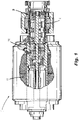
Fig. 2 is a schematic cross sectional view of the rotating rectifier assembly ofFig. 2 , showing a mounting ring assembly; -
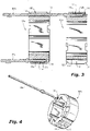
Fig. 3 is a schematic cross sectional view of the mounting ring assembly ofFig. 2 ; -
Fig. 4 is a perspective view of the mounting ring assembly ofFig. 3 ; and -
Fig. 5 is a schematic box diagram of a method in accordance with at least one aspect of this disclosure. - Reference will now be made to the drawings wherein like reference numerals identify similar structural features or aspects of the subject disclosure. For purposes of explanation and illustration, and not limitation, a partial view of an embodiment of an assembly in accordance with the disclosure is shown in
Fig. 1 and is designated generally by reference character 100. Other embodiments of systems in accordance with the disclosure, or aspects thereof, are provided inFigs. 2-5 , as will be described. The systems and methods described herein can be used to improve conductivity of a rotating rectifier assembly. - Shown in
Fig. 1 , an assembly 100 can included a mounting ring 102 for a rotating rectifier assembly (RRA) 10 which can be mounted in a generator 1 (e.g. a brushless and/or variable frequency generator (VFG)). The mounting ring 102 can have apin bore 104 defined in the mounting ring 102 oriented in an axial direction (e.g. along axis A). In embodiments, the mounting ring 102 can be of Aluminum, however any suitable conductive material can be used. - At least one contact band 106 can be seated in the
pin bore 104 of the mounting ring 102 for mounting a direct current (DC) pin 108 to the mounting ring 102. The at least one contact band 106 can allow for precise, durable positioning of the DC pin 108 within the mounting ring 102. The at least one contact band 106 can be of a metallic material, for example a material that allows the DC pin 108 to electrically connect between diodes 110 and a field winding 112 of theVFG 1 for rectifying alternating current (AC) to DC in theRRA 10. Both the mounting ring 102 and at least one contact band 106 can be free of BeCu, however it is contemplated that the entire assembly 100 as described herein can be free of BeCu. - A
respective joining interface 114 can be formed between each of the at least one contact bands 106 and the mounting ring 102. Brazing the DC pin 108 to the mounting ring 102 can weaken the assembly 100, therefore thejoining interface 114 can be free of braze. Eachrespective joining interface 114 of the at least one contact band 106 can be an interference fit, for example, the at least one contact band 106 can be spring type contact band. The at least one contact band 106 can include afirst contact band 106a and asecond contact band 106b. Thefirst contact band 106a can be axially stacked with thesecond contact band 106b within the pin bore 104. - At least one
axial channel 116 can be included on a radiallyouter surface 118 of the mounting ring 102 for accommodating a DC pin 108 of another mounting ring 102 in the RRA10. For example, the mounting ring 102 can be afirst mounting ring 102a and the assembly 100 can include asecond mounting ring 102b, and the DC pin 108 can be a first DC pin 108. The second a mountingring 102b can also have a pin bore 104b defined therein in the axial direction, as described for the mountingring 102a. Thesecond mounting ring 102b can also include at least onecontact band 120a,b seated within the pin bore 104b Thesecond DC pin 108b can pass through theaxial channel 116 of thefirst mounting ring 102a, and through the pin bore 104b of thesecond mounting ring 102b, as shown inFigs. 3-4 . At least onecircumferential coolant channel 122 can be defined on radiallyouter surface 118 of the mountingring 102a,b, for example, each mountingring 102a,b can include acoolant channel 122 on each axial end of the mountingring 102a,b. - Shown in
Fig. 5 .method 200 comprises forming a mounting ring 102 for anRRA 10, including forming 202 apin bore 104 in the mounting ring 102 oriented in an axial direction, and installing 204 at least one contact band 106 into a the pin bore 104 of the mounting ring 102. Themethod 200 can include mounting 206 a DC pin to the mounting ring 102 by seating the DC pin 108 in the at least one contact band 106. Themethod 200 can also include assembling 208 the mounting ring into theRRA 10. - Assembling 210 a second a mounting
ring 102b to theRRA 10 can be included in themethod 200, wherein a pin bore 104b can be defined in thesecond mounting ring 102b oriented in the axial direction, and at least onecontact band 120a,b can be seated in the pin bore 104b of thesecond mounting ring 102b. Themethod 200 can further include mounting 212 asecond DC pin 108b seated in the at least onecontact band 120a,b of thesecond mounting ring 102b, wherein thesecond DC pin 108b can pass through anaxial channel 116 on a radiallyouter surface 118 of thefirst mounting ring 102a. - The methods and systems of the present disclosure, as described above and shown in the drawings, provide for decreased complexity in assembly, reduced manufacturing cost and compliance requirements, improved cooling and thermal conductivity, and improved conductivity. While the apparatus and methods of the subject disclosure have been shown and described, those skilled in the art will readily appreciate that changes and/or modifications may be made thereto without departing from the scope of the subject disclosure.
Claims (15)
- An assembly comprising:a mounting ring (102) for a rotating rectifier assembly, RRA (10), wherein a pin bore (104) is defined in the mounting ring (102) oriented in an axial direction; andat least one contact band (106) seated in the pin bore (104) of the mounting ring for mounting a direct current, DC, pin (108) to the mounting ring (102).
- The assembly as recited in claim 1, wherein a respective joining interface (114) is formed between each of the at least one contact bands (106) and the mounting ring (102), wherein the joining interface (114) is free of braze, and preferably wherein each respective joining interface (114) of the at least one contact bands is an interference fit.
- The assembly as recited in claim 1 or 2, wherein the at least one contact band (106) includes a first contact band (106a) and a second contact band (106b), wherein the first contact band is axially stacked with the second contact band within the pin bore (104).
- The assembly as recited in any preceding claim, wherein the mounting ring (102) is of Aluminum; and/or
wherein the at least one contact band (106) is of a metallic material. - The assembly as recited in any preceding claim, further comprising at least one axial channel (116) on a radially outer surface (118) of the mounting ring (102) for accommodating a DC pin of another mounting ring in the RRA (10).
- The assembly as recited in any preceding claim, wherein at least one circumferential coolant channel (122) is defined on an outward surface of the mounting ring (102).
- The assembly as recited in any preceding claim, further comprising a DC pin (108) seated in the at least one contact band (106).
- The assembly as recited in claim 7, wherein the mounting ring (102) is a first mounting ring (102a), and the DC pin is a first DC pin (108a), and further comprising:a second a mounting ring (102b) for an RRA, wherein a pin bore (104b) is defined in the second mounting ring (102b) oriented in the axial direction;at least one contact band (106) seated in the pin bore (104b) of the second mounting ring (102b); anda second DC pin (108b) seated in the at least one contact band (106) of the second mounting ring (102b), wherein the second DC pin (108b) passes through an axial channel on a radially outer surface of the first mounting ring (108a).
- The assembly as recited in claim 8, wherein the assembly is free of Beryllium Copper (BeCu); and/or wherein the contact bands (106) are spring type contact bands.
- The assembly as recited in claim 8 or 9, wherein the first and second mounting rings (102a, 102b) are assembled into the RRA of a variable frequency generator, VFG, and preferably wherein the first and second DC pins (108a, 108b) electrically connect between diodes and a field winding of the VFG for rectifying alternating current, AC, to DC in the RRA
- A method comprising:forming a mounting ring for a rotating rectifier assembly, RRA, including forming a pin bore in the mounting ring oriented in an axial direction; andinstalling at least one contact band into the pin bore of the mounting ring.
- The method as recited in claim 11, further comprising mounting a direct current, DC, pin to the mounting ring by seating the DC pin in the at least one contact band.
- The method as recited in claim 12, further comprising assembling the mounting ring into an RRA, wherein the mounting ring is a first mounting ring, and the DC pin is a first DC pin, and further comprising:assembling a second a mounting ring to the RRA, wherein a pin bore is defined in the second mounting ring oriented in the axial direction, and at least one contact band is seated in a the pin bore of the second mounting ring; andmounting a second DC pin seated in the at least one contact band of the second mounting ring, wherein the second DC pin passes through an axial channel on a radially outer surface of the first mounting ring.
- The method as recited in claim 13, wherein the contact bands are spring type contact bands and are assembled with interference fits into the respective first and second mounting rings without braze.
- The method as recited in claim 13 or 14, wherein the first and second mounting rings are assembled into the RRA of a variable frequency generator, VFG, and preferably further comprising electrically connecting the first and second DC pins between diodes and a field winding of the VFG for rectifying AC to DC in the RRA
Applications Claiming Priority (1)
| Application Number | Priority Date | Filing Date | Title |
|---|---|---|---|
| US17/200,823 US11799391B2 (en) | 2021-03-13 | 2021-03-13 | Diode mounting ring with contact band inserts |
Publications (1)
| Publication Number | Publication Date |
|---|---|
| EP4068590A1 true EP4068590A1 (en) | 2022-10-05 |
Family
ID=80685198
Family Applications (1)
| Application Number | Title | Priority Date | Filing Date |
|---|---|---|---|
| EP22161302.9A Pending EP4068590A1 (en) | 2021-03-13 | 2022-03-10 | Diode mounting ring with contact band inserts |
Country Status (2)
| Country | Link |
|---|---|
| US (1) | US11799391B2 (en) |
| EP (1) | EP4068590A1 (en) |
Citations (3)
| Publication number | Priority date | Publication date | Assignee | Title |
|---|---|---|---|---|
| GB2473535A (en) * | 2009-09-14 | 2011-03-16 | Hamilton Sundstrand Corp | Grounding bush for a rotor busbar in a generator |
| US20140210320A1 (en) * | 2013-01-29 | 2014-07-31 | Powerex, Inc. | Electric machine and rectifier assembly therefor |
| US20180316248A1 (en) * | 2017-04-28 | 2018-11-01 | Hamilton Sundstrand Corporation | Rotating rectifier assembly |
Family Cites Families (14)
| Publication number | Priority date | Publication date | Assignee | Title |
|---|---|---|---|---|
| US4492887A (en) | 1983-08-25 | 1985-01-08 | Sundstrand Corporation | Compact resistor assembly for rotary electric machine |
| US5219617A (en) * | 1989-09-19 | 1993-06-15 | Michigan Chrome And Chemical Company | Corrosion resistant coated articles and process for making same |
| JP2679499B2 (en) * | 1991-12-27 | 1997-11-19 | 三菱電機株式会社 | Circuit breaker and switch operating mechanism |
| US20080218035A1 (en) * | 2007-03-09 | 2008-09-11 | C.E. Niehoff & Co. | Rotating rectifier assembly |
| US9035508B2 (en) | 2012-05-08 | 2015-05-19 | Hamilton Sundstrand Corporation | Rotating resistor assembly |
| US9474189B2 (en) * | 2012-05-23 | 2016-10-18 | Mitsubishi Electric Corporation | Inverter device |
| US20140226383A1 (en) | 2013-02-11 | 2014-08-14 | Hamilton Sundstrand Corporation | Coaxial rotating rectifier package assembly for generator |
| US9312742B2 (en) | 2013-03-01 | 2016-04-12 | Hamilton Sundstrand Corporation | Connector and spring assembly for a generator |
| US9912213B2 (en) * | 2015-02-02 | 2018-03-06 | Hamilton Sundstrand Corporation | Rotating rectifiers with nested diodes |
| EP3587832B1 (en) | 2018-06-24 | 2024-04-03 | Hamilton Sundstrand Corporation | Servo valve housing |
| US10460861B1 (en) | 2018-10-29 | 2019-10-29 | Hamilton Sundstrand Corporation | High speed rotor connection assembly |
| TWI679830B (en) | 2019-01-04 | 2019-12-11 | 建準電機工業股份有限公司 | Motor and ceiling fan including the same |
| US10879772B2 (en) | 2019-01-08 | 2020-12-29 | Hamilton Sundstrand Corporation | Rotating resistor assemblies |
| US11245312B2 (en) | 2019-06-28 | 2022-02-08 | Hamilton Sundstrand Corporation | High speed generator connection assembly |
-
2021
- 2021-03-13 US US17/200,823 patent/US11799391B2/en active Active
-
2022
- 2022-03-10 EP EP22161302.9A patent/EP4068590A1/en active Pending
Patent Citations (3)
| Publication number | Priority date | Publication date | Assignee | Title |
|---|---|---|---|---|
| GB2473535A (en) * | 2009-09-14 | 2011-03-16 | Hamilton Sundstrand Corp | Grounding bush for a rotor busbar in a generator |
| US20140210320A1 (en) * | 2013-01-29 | 2014-07-31 | Powerex, Inc. | Electric machine and rectifier assembly therefor |
| US20180316248A1 (en) * | 2017-04-28 | 2018-11-01 | Hamilton Sundstrand Corporation | Rotating rectifier assembly |
Also Published As
| Publication number | Publication date |
|---|---|
| US11799391B2 (en) | 2023-10-24 |
| US20220294315A1 (en) | 2022-09-15 |
Similar Documents
| Publication | Publication Date | Title |
|---|---|---|
| KR20210145656A (en) | Combined insulator and conductor assembly for bearings with clip-mounted conductor | |
| JP2021162156A (en) | Composite insulators and conductor assemblies for bearings with fixed conductors | |
| EP2918004B1 (en) | Electric motor | |
| US20180316248A1 (en) | Rotating rectifier assembly | |
| JP6752323B1 (en) | Stator winding of rotary electric machine and its manufacturing method | |
| CN107800255B (en) | Induction rotor and method of assembling an induction rotor | |
| JP2014166138A (en) | Rotating rectifier assembly for electric machine | |
| KR20010093641A (en) | Stator for an automotive alternator | |
| EP3681020B1 (en) | Rotating resistor assemblies | |
| US9812834B2 (en) | Rotor of rotating electric machine | |
| CN103904803A (en) | Hairpin and hairpin winding motors with hairpin | |
| US11799391B2 (en) | Diode mounting ring with contact band inserts | |
| EP2166643B1 (en) | Method of manufacturing rotor for dynamoelectric machine | |
| US11621601B2 (en) | Generator main field connection | |
| EP3716447A1 (en) | Generators with flat wire windings and methods of making generators with flat wire windings | |
| EP4064299A1 (en) | Resistor plate assembly with contact bands | |
| CN102549887B (en) | Electric machine | |
| CN103944299B (en) | Method For Connecting Lead Wires Of Phase Winding Of Stator Winding Of Motor And Motor Thereof | |
| US7247966B2 (en) | Flexible rotor pole crossover for a generator | |
| CN102498644B (en) | Electrical motor | |
| US2251152A (en) | Winding for electrical apparatus | |
| JP6689125B2 (en) | Rotating electric machine and method of manufacturing rotating electric machine | |
| CN102630366B (en) | Cooling device for use in a rectifier unit of an electric motor | |
| US7148600B1 (en) | Electrical current transferring and brush pressure exerting interlocking slip ring assembly | |
| JP2002262519A (en) | Commutator for rotating electric machine and method of manufacturing the same |
Legal Events
| Date | Code | Title | Description |
|---|---|---|---|
| PUAI | Public reference made under article 153(3) epc to a published international application that has entered the european phase |
Free format text: ORIGINAL CODE: 0009012 |
|
| STAA | Information on the status of an ep patent application or granted ep patent |
Free format text: STATUS: THE APPLICATION HAS BEEN PUBLISHED |
|
| AK | Designated contracting states |
Kind code of ref document: A1 Designated state(s): AL AT BE BG CH CY CZ DE DK EE ES FI FR GB GR HR HU IE IS IT LI LT LU LV MC MK MT NL NO PL PT RO RS SE SI SK SM TR |
|
| STAA | Information on the status of an ep patent application or granted ep patent |
Free format text: STATUS: REQUEST FOR EXAMINATION WAS MADE |
|
| 17P | Request for examination filed |
Effective date: 20230404 |
|
| RBV | Designated contracting states (corrected) |
Designated state(s): AL AT BE BG CH CY CZ DE DK EE ES FI FR GB GR HR HU IE IS IT LI LT LU LV MC MK MT NL NO PL PT RO RS SE SI SK SM TR |
|
| STAA | Information on the status of an ep patent application or granted ep patent |
Free format text: STATUS: EXAMINATION IS IN PROGRESS |
|
| 17Q | First examination report despatched |
Effective date: 20250616 |