EP4068576A1 - Hybrid axial/radial electric motor - Google Patents
Hybrid axial/radial electric motor Download PDFInfo
- Publication number
- EP4068576A1 EP4068576A1 EP22166163.0A EP22166163A EP4068576A1 EP 4068576 A1 EP4068576 A1 EP 4068576A1 EP 22166163 A EP22166163 A EP 22166163A EP 4068576 A1 EP4068576 A1 EP 4068576A1
- Authority
- EP
- European Patent Office
- Prior art keywords
- stator
- radial
- segment
- axial
- central rotor
- Prior art date
- Legal status (The legal status is an assumption and is not a legal conclusion. Google has not performed a legal analysis and makes no representation as to the accuracy of the status listed.)
- Pending
Links
Images



Classifications
-
- H—ELECTRICITY
- H02—GENERATION; CONVERSION OR DISTRIBUTION OF ELECTRIC POWER
- H02K—DYNAMO-ELECTRIC MACHINES
- H02K1/00—Details of the magnetic circuit
- H02K1/06—Details of the magnetic circuit characterised by the shape, form or construction
- H02K1/22—Rotating parts of the magnetic circuit
- H02K1/27—Rotor cores with permanent magnets
- H02K1/2793—Rotors axially facing stators
- H02K1/2795—Rotors axially facing stators the rotor consisting of two or more circumferentially positioned magnets
- H02K1/2796—Rotors axially facing stators the rotor consisting of two or more circumferentially positioned magnets where both axial sides of the rotor face a stator
-
- H—ELECTRICITY
- H02—GENERATION; CONVERSION OR DISTRIBUTION OF ELECTRIC POWER
- H02K—DYNAMO-ELECTRIC MACHINES
- H02K16/00—Machines with more than one rotor or stator
- H02K16/04—Machines with one rotor and two stators
-
- H—ELECTRICITY
- H02—GENERATION; CONVERSION OR DISTRIBUTION OF ELECTRIC POWER
- H02K—DYNAMO-ELECTRIC MACHINES
- H02K1/00—Details of the magnetic circuit
- H02K1/06—Details of the magnetic circuit characterised by the shape, form or construction
- H02K1/22—Rotating parts of the magnetic circuit
- H02K1/32—Rotating parts of the magnetic circuit with channels or ducts for flow of cooling medium
-
- H—ELECTRICITY
- H02—GENERATION; CONVERSION OR DISTRIBUTION OF ELECTRIC POWER
- H02K—DYNAMO-ELECTRIC MACHINES
- H02K1/00—Details of the magnetic circuit
- H02K1/06—Details of the magnetic circuit characterised by the shape, form or construction
- H02K1/12—Stationary parts of the magnetic circuit
- H02K1/20—Stationary parts of the magnetic circuit with channels or ducts for flow of cooling medium
-
- H—ELECTRICITY
- H02—GENERATION; CONVERSION OR DISTRIBUTION OF ELECTRIC POWER
- H02K—DYNAMO-ELECTRIC MACHINES
- H02K1/00—Details of the magnetic circuit
- H02K1/06—Details of the magnetic circuit characterised by the shape, form or construction
- H02K1/22—Rotating parts of the magnetic circuit
- H02K1/27—Rotor cores with permanent magnets
- H02K1/2793—Rotors axially facing stators
Definitions
- the present invention relates to electric machines, and more specifically, to a hybrid axial/radial elector motor.
- Electric motors can be used for a wide variety of applications. Electric motors are operated by controlling an electromagnetic field to generate a force to move a rotor which can be attached to a shaft to do work. Different types of applications can require different output characteristics such as high speed, high torque, etc. These output characteristics are generally trade-offs from each other due to the physical arrangements of the different types of motors such as axial motors and radial motors. Challenges may exist for applications that require both high torque and high-speed capabilities. There may be a need to improve the electric motor characteristics to include high speed and high torque characteristics into a single motor.
- a hybrid electric motor can include a central rotor, wherein the central rotor includes an axial segment, a first radial segment, and a second radial segment, wherein the first radial segment extends axially from a first side of the axial segment and the second radial segment extends axially from a second side of the axial segment, wherein the first side is opposite the second side; and a stator adapted to receive the first radial segment or the second radial segment of the central rotor.
- Further embodiments include a diameter of the axial segment of the central rotor that is larger than a diameter of the first radial segment and the second radial segment of the central rotor.
- inventions include an axial segment that includes a plurality of magnets that are arranged to convey an electromagnetic field in an axial direction during operation.
- inventions include an outer diameter of the axial segment that is adapted to drive a load.
- Further embodiments include a plurality of cooling vents arranged on the central rotor to cool the central rotor during operation.
- Further embodiments include a plurality of cooling vents arranged the first stator or the second stator to cool the stator during operation.
- a method for operating a hybrid electric motor can include arranging a central rotor and a stator, wherein the central rotor comprises an axial segment and a radial segment, wherein the stator comprises a stator axial core and a stator radial core; coupling the axial segment of the central rotor to the stator axial core of the stator; and coupling the radial segment of the central rotor to the stator radial core of the stator.
- a radial segment that includes an arrangement having a first radial segment that extends from a first side of the axial segment and a second radial segment that extends from a second side of the axial segment, wherein the first side is opposite the second side.
- Further embodiments include coupling the plurality of axial rotor magnets to the stator axial core that conveys a magnetic flux in an axial direction.
- Further embodiments include coupling the plurality of radial rotor magnets to the stator radial core that conveys a magnetic flux in a radial direction.
- Further embodiments include cooling the central rotor using a plurality of cooling vents arranged on the central rotor, and cooling the stator using a plurality of cooling vents arranged on the stator.
- Further embodiments include selecting a diameter of the axial segment of the central rotor to be larger than a diameter of the radial segment of the central rotor.
- Further embodiments include driving a load using an outer diameter of the axial segment.
- Further embodiments include driving a load using a shaft coupled to the central rotor.
- motors can be used in high-performance applications such as electric actuators, variable-speed motor drives, etc.
- Motors can be designed for high-torque applications or high-speed applications.
- High-torque motor designs have large diameter rotors which effectively provide a long lever arm that produces a high torque. Therefore, the large diameter rotors are not typically operated at high speed given its dimensions.
- high-speed motors do not traditionally provide high torque.
- Conventional high-speed motors use radial magnetic flux fields to increase the ability of the motor to operate at a high speed
- the techniques of one or more embodiments of the disclosure described herein include integrating an axial flux motor with a radial flux motor into a single hybrid electric motor architecture.
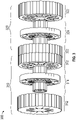
- FIG. 1 depicts a schematic diagram illustrating components of a hybrid axial/radial electric motor 100 (hereinafter referred to as "motor 100") in accordance with one or more embodiments of the disclosure.
- the motor 100 can include a central rotor 102 and the stator 106.
- the rotor 102 and the stator 106 can be made of composites or non-magnetic alloys of any type capable of withstanding temperature requirements of the motor 100.
- the central rotor 102 and the stator 106 can be composed of structure composites such as but not limited to carbon fiber or a carbon matrix, carbon/glass/polybenzobisoxazole (PBO) fibers with a polymer matrix, etc.
- PBO polybenzobisoxazole
- the central rotor 102 and the stator 106 can be composed of functional composites such as but not limited to soft magnetic core composites (polymer matrix with metal particles).
- the material for the stator can also be an injection molded component that surrounds the individual stator cores that is capable of holding them in place.
- the motor 100 operates when an electric current or power source is fed to the windings of coils in the stator 106 which then creates a force that interacts with the magnetic components (e.g., permanent magnets) embedded in the central rotor 102 causing it to rotate (further discussed below).
- the central rotor 102 may include one or more radial segments 108 and axial segment 110.
- the radial segment 108 extends outwardly from the axial segment 110 of the central rotor 102.
- the axial segment 110 can include a plate-like or disc-like structure where a plurality of axial rotor magnets 112 can be arranged thereto.
- the poles of the axial rotor magnets 112 can be arranged to convey an electromagnetic field in an axial direction.
- the axial rotor magnets 112 can be magnetically coupled to the stator axial core 114 of the stator 106 during the operation of the motor 100.
- the magnetic elements can be arranged as a Halbach array or in the case that radial magnets are used, the radial magnets can be supported underneath by a steel sleeve.
- An outer layer of the magnetic elements can be covered by a sleeve in the radial direction and a cover in the axial direction where the sleeve and cover function to keep the magnets in place under the stresses and slippages caused by operation of the motor 100.
- the sleeve can include a fiber-reinforced radial sleeve where the fiber can include carbon, aramid, glass and PBO fibers to name a few.
- a matrix can include materials such as but not limited to thermoplastic and thermoset polymers such as epoxy, aramid, and phenolic resins.
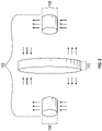
- FIG. 2 an expanded view of the central rotor 102 of FIG. 1 is provided.
- a simplified illustration of the radial segment 108 depicts a non-limiting representation of the field that can be conveyed in the radial direction represented by the arrows.
- the arrows for the axial segment 110 provide a non-limiting representation of the field that can be conveyed in the axial direction.
- the axial direction is perpendicular to the radial direction as shown in FIG. 2 .
- the dashed lines represent the location on the axial segment 110 where the radial segment(s) 108 are attached.
- a heteropolar flux path and/or a homopolar flux path can be implemented for torque generation of the motor 100.
- the central rotor 102 is a single integrated part or component that includes the axial segment 110 and the radial segment(s) 108.
- the radial segment(s) 108 (a first radial segment and a second radial segment) and axial segment 110 are physically fixed together and rotate together during the operation of the motor 100.
- the second radial segment 108 is not visible in the perspective view but includes corresponding components as the first radial segment 108 that is visible.
- the axial segment 110 of the central rotor 102 can include a plurality of vents 140 in the plate-like structure of the central rotor 102 to form an air gap for cooling.
- the center of the central rotor 102 can include an opening 130 for a shaft (not shown) or conduit for cables (not shown).
- the stator 106 can include a stator radial core 122 and the stator axial core 114.
- FIGS. 5A and 5B illustrate an example of different perspective views of the stator.
- FIG. 1 illustrates a perspective view where some components are may not be visible, it should be understood the stator 106 on the right of the central rotor 102 and the stator 106 on the left of the central rotor 102 both include corresponding components that are described herein.
- the stator 106 includes an opening 120 located that is adapted to receive the radial segment 108 of the central rotor 102.
- An inner surface of the opening in the stator 106 can include a stator radial core 122 which includes a plurality of magnetic components such as coils, windings, magnets, etc.
- FIG. 6A depicts an example magnetic component 114 such as the coil that can be used in the stator 106.
- FIG. 6B depicts a example of the stator core that does not include the coil.
- the stator radial core 122 is magnetically coupled to the radial rotor magnets 134 during operation and causes the rotation of the central rotor 102.
- the poles of the radial rotor magnets 134 can be arranged to convey an electromagnetic field in the radial direction.
- the stator axial core 114 of the stator 106 can be arranged on the surface of the sidewall of the stator 106 or integrated into the stator 106.
- the stator axial core 114 can be magnetically coupled to the axial rotor magnets 112 during the operation of the motor 100.
- the poles of the axial rotor magnets 112 can be arranged to convey an electromagnetic field in an axial direction.
- the axial rotor magnets 112 can be magnetically coupled to the stator axial core 112 of the stator 106 during the operation of the motor 100.
- the diameter of the axial segment 110 of the central rotor 102 wherein the larger diameter provides an effective longer lever arm and the ability to increase the number of magnetic poles to achieve high torque characteristics.
- the diameter of the radial segment 108 can have a smaller diameter than the axial segment 110 which enables the ability for high-speed applications.
- FIG. 1 depicts a number of magnetic elements for the radial rotor magnets 134, the axial rotor magnets 112, the stator radial core 122, and the stator axial core 114, it should be understood that any number of magnetic elements can be envisioned to be within the scope of the disclosure and is not intended to be limited by the illustration of the figures.
- the stator 106 can include a plurality of vents 126 to cool the stator 106 during operation.
- the central rotor 102 can include a plurality of vents 140.
- the vents can be omitted and other cooling mechanisms or cooling circuits can be used.
- a liquid cooling circuit can be used to directly cool the stator core, where the liquid cooling circuit can include tubes entering and existing the stator core (not shown).
- the illustrations of vents 126, 140 are not intended to limit the scope of the disclosure but are merely representative of the vents that are envisioned to be within the scope of the embodiments of the disclosure.
- One or more illustrative embodiments of the disclosure are described herein. Such embodiments are merely illustrative of the scope of this disclosure and are not intended to be limiting in any way. Accordingly, variations, modifications, and equivalents of embodiments disclosed herein are also within the scope of this disclosure.
- FIG. 3 depicts a schematic diagram of a multi-hybrid axial/radial electric motor 300 (hereinafter referred to as "motor 300" in accordance with one or more embodiments of the disclosure.
- FIG. 3 depicts the combined motor such as that shown in FIG. 1 .
- Each of the portion 310, 320 of the motor 300 includes its respective the central rotor 314, 324, the respective stators 312, 322, and other corresponding components discussed with reference to FIG. 1 .
- the stator 312 of the first portion 310 is coupled to a neighboring stator 312 of the second portions to form the motor 300.
- FIG. 4 depicts a flowchart of a method 400 for operating a hybrid axial/radial electric motor in accordance with one or more embodiments of the disclosure.
- the method 400 can be implemented in the system 100 or 300 or any other similar type of system.
- the method 400 begins at block 402 and proceeds to block 404 which provides for arranging a central rotor and a stator, wherein the central rotor comprises an axial segment and a radial segment, wherein the stator comprises a stator axial core and a stator radial core.
- the stator includes a first stator and a second stator, wherein the first stator includes a stator radial core and a stator axial core and is adapted to receive the first radial segment, and the second stator includes a stator radial core and a stator axial core and is adapted to receive the second radial segment.
- Block 406 couples the axial segment of the central rotor to a stator axial core of the stator.
- Block 408 coupling the radial segment of the central rotor to a stator radial core in the stator.
- the method 400 ends at block 410. It should be understood the steps provided in FIG. 4 are not intended to be limiting but represent a non-limiting example of steps that are considered to be within the scope of the disclosure.
- the technical effects and benefits include combining both the radial and axial components of different motors into a single hybrid electric motor architecture to achieve both high-torque and high-speed characteristics.
- the high torque features from the larger diameter rotor of an axial motor and the high-speed features from a smaller diameter of the radial motor are realized in the combined architecture.
- the motor can be scaled as needed for the selected application which increases the versatility of the hybrid motor.
Landscapes
- Engineering & Computer Science (AREA)
- Power Engineering (AREA)
- Iron Core Of Rotating Electric Machines (AREA)
Abstract
Description
- The present invention relates to electric machines, and more specifically, to a hybrid axial/radial elector motor.
- Electric motors can be used for a wide variety of applications. Electric motors are operated by controlling an electromagnetic field to generate a force to move a rotor which can be attached to a shaft to do work. Different types of applications can require different output characteristics such as high speed, high torque, etc. These output characteristics are generally trade-offs from each other due to the physical arrangements of the different types of motors such as axial motors and radial motors. Challenges may exist for applications that require both high torque and high-speed capabilities. There may be a need to improve the electric motor characteristics to include high speed and high torque characteristics into a single motor.
- According to one aspect, a hybrid electric motor is provided. The motor can include a central rotor, wherein the central rotor includes an axial segment, a first radial segment, and a second radial segment, wherein the first radial segment extends axially from a first side of the axial segment and the second radial segment extends axially from a second side of the axial segment, wherein the first side is opposite the second side; and a stator adapted to receive the first radial segment or the second radial segment of the central rotor.
- Further embodiments include a stator that includes a first stator and a second stator, wherein the first stator further includes a first stator radial core and a first stator axial core and is adapted to receive the first radial segment, and the second stator further includes a second stator radial core and a second stator axial core and is adapted to receive the second radial rotor segment.
- Further embodiments include an axial segment, a first radial segment, and a second radial segment that are a single integrated part.
- Further embodiments include a diameter of the axial segment of the central rotor that is larger than a diameter of the first radial segment and the second radial segment of the central rotor.
- Further embodiments include an axial segment that includes a plurality of magnets that are arranged to convey an electromagnetic field in an axial direction during operation.
- Further embodiments include a first radial segment and the second radial segment that further include a plurality of magnets that are arranged to convey an electromagnetic field in a radial direction during operation.
- Further embodiments include an outer diameter of the axial segment that is adapted to drive a load.
- Further embodiments include a shaft coupled to the central rotor that is adapted to drive a load.
- Further embodiments include a plurality of cooling vents arranged on the central rotor to cool the central rotor during operation.
- Further embodiments include a plurality of cooling vents arranged the first stator or the second stator to cool the stator during operation.
- According to one aspect, a method for operating a hybrid electric motor is provided. The method can include arranging a central rotor and a stator, wherein the central rotor comprises an axial segment and a radial segment, wherein the stator comprises a stator axial core and a stator radial core; coupling the axial segment of the central rotor to the stator axial core of the stator; and coupling the radial segment of the central rotor to the stator radial core of the stator.
- Further embodiments include a radial segment that includes an arrangement having a first radial segment that extends from a first side of the axial segment and a second radial segment that extends from a second side of the axial segment, wherein the first side is opposite the second side.
- Further embodiments include a stator having an arrangement including a first stator and a second stator, wherein the first stator further includes a first stator radial core and a stator axial core and is adapted to receive the first radial segment, and the second stator further includes a second stator radial core and a stator axial core and is adapted to receive the second radial segment.
- Further embodiments include arranging a plurality of axial rotor magnets on the axial segment of the central rotor, and arranging a plurality of radial rotor magnets of the radial segment of the central rotor.
- Further embodiments include coupling the plurality of axial rotor magnets to the stator axial core that conveys a magnetic flux in an axial direction.
- Further embodiments include coupling the plurality of radial rotor magnets to the stator radial core that conveys a magnetic flux in a radial direction.
- Further embodiments include cooling the central rotor using a plurality of cooling vents arranged on the central rotor, and cooling the stator using a plurality of cooling vents arranged on the stator.
- Further embodiments include selecting a diameter of the axial segment of the central rotor to be larger than a diameter of the radial segment of the central rotor.
- Further embodiments include driving a load using an outer diameter of the axial segment.
- Further embodiments include driving a load using a shaft coupled to the central rotor.
- The foregoing features and elements may be combined in various combinations without exclusivity, unless expressly indicated otherwise. These features and elements as well as the operation thereof will become more apparent in light of the following description and the accompanying drawings. It should be understood, however, that the following description and drawings are intended to be illustrative and explanatory in nature and non-limiting.
- The following descriptions should not be considered limiting in any way. With reference to the accompanying drawings, like elements are numbered alike:
-
FIG. 1 is a schematic diagram illustrating components of a hybrid axial/radial electric motor in accordance with one or more embodiments of the disclosure; -
FIG. 2 depicts an illustration of the expanded view of the central rotor in accordance with one or more embodiments of the disclosure; -
FIG. 3 is a schematic diagram of a multiple hybrid axial/radial electric motor in accordance with one or more embodiments of the disclosure; -
FIG. 4 is a flowchart of a method for operating the hybrid axial/radial electric motor in accordance with one or more embodiments of the disclosure; -
FIG. 5A and 5B provide different perspective views of an example stator cores in accordance with one or more embodiments of the disclosure; and -
FIG. 6A and 6B provide examples of a coil of the stator core in accordance with one or more embodiments of the disclosure. - In today's environment motors can be used in high-performance applications such as electric actuators, variable-speed motor drives, etc. Motors can be designed for high-torque applications or high-speed applications. High-torque motor designs have large diameter rotors which effectively provide a long lever arm that produces a high torque. Therefore, the large diameter rotors are not typically operated at high speed given its dimensions. On the other hand, high-speed motors do not traditionally provide high torque. Conventional high-speed motors use radial magnetic flux fields to increase the ability of the motor to operate at a high speed The techniques of one or more embodiments of the disclosure described herein include integrating an axial flux motor with a radial flux motor into a single hybrid electric motor architecture.
-
FIG. 1 depicts a schematic diagram illustrating components of a hybrid axial/radial electric motor 100 (hereinafter referred to as "motor 100") in accordance with one or more embodiments of the disclosure. Themotor 100 can include acentral rotor 102 and thestator 106. In one or more embodiments, therotor 102 and thestator 106 can be made of composites or non-magnetic alloys of any type capable of withstanding temperature requirements of themotor 100. In a non-limiting example, thecentral rotor 102 and thestator 106 can be composed of structure composites such as but not limited to carbon fiber or a carbon matrix, carbon/glass/polybenzobisoxazole (PBO) fibers with a polymer matrix, etc. In a different non-limiting example, thecentral rotor 102 and thestator 106 can be composed of functional composites such as but not limited to soft magnetic core composites (polymer matrix with metal particles). In other embodiments, the material for the stator can also be an injection molded component that surrounds the individual stator cores that is capable of holding them in place. In some embodiments, themotor 100 operates when an electric current or power source is fed to the windings of coils in thestator 106 which then creates a force that interacts with the magnetic components (e.g., permanent magnets) embedded in thecentral rotor 102 causing it to rotate (further discussed below). Thecentral rotor 102 may include one or moreradial segments 108 andaxial segment 110. Theradial segment 108 extends outwardly from theaxial segment 110 of thecentral rotor 102. As shown inFIG. 1 , theaxial segment 110 can include a plate-like or disc-like structure where a plurality ofaxial rotor magnets 112 can be arranged thereto. The poles of theaxial rotor magnets 112 can be arranged to convey an electromagnetic field in an axial direction. Theaxial rotor magnets 112 can be magnetically coupled to the statoraxial core 114 of thestator 106 during the operation of themotor 100. In some embodiments, the magnetic elements can be arranged as a Halbach array or in the case that radial magnets are used, the radial magnets can be supported underneath by a steel sleeve. It should be understood that other magnetic arrangements can be used and is not limited by the disclosure provided herein. An outer layer of the magnetic elements can be covered by a sleeve in the radial direction and a cover in the axial direction where the sleeve and cover function to keep the magnets in place under the stresses and slippages caused by operation of themotor 100. In one or more embodiments, the sleeve can include a fiber-reinforced radial sleeve where the fiber can include carbon, aramid, glass and PBO fibers to name a few. In addition, a matrix can include materials such as but not limited to thermoplastic and thermoset polymers such as epoxy, aramid, and phenolic resins. With reference toFIG. 2 , an expanded view of thecentral rotor 102 ofFIG. 1 is provided. A simplified illustration of the radial segment 108 (permanent magnets are not shown) depicts a non-limiting representation of the field that can be conveyed in the radial direction represented by the arrows. Similarly, the arrows for the axial segment 110 (permanent magnets are not shown) provide a non-limiting representation of the field that can be conveyed in the axial direction. In one or more embodiments, the axial direction is perpendicular to the radial direction as shown inFIG. 2 . The dashed lines represent the location on theaxial segment 110 where the radial segment(s) 108 are attached. In one or more embodiments of the disclosure, a heteropolar flux path and/or a homopolar flux path can be implemented for torque generation of themotor 100. - Referring to
FIG. 1 , in one or more embodiments of the disclosure, thecentral rotor 102 is a single integrated part or component that includes theaxial segment 110 and the radial segment(s) 108. InFIG. 1 , the radial segment(s) 108 (a first radial segment and a second radial segment) andaxial segment 110 are physically fixed together and rotate together during the operation of themotor 100. InFIG. 1 , it can be appreciated the secondradial segment 108 is not visible in the perspective view but includes corresponding components as the firstradial segment 108 that is visible. - In one or more embodiments of the disclosure, the
axial segment 110 of thecentral rotor 102 can include a plurality ofvents 140 in the plate-like structure of thecentral rotor 102 to form an air gap for cooling. The center of thecentral rotor 102 can include anopening 130 for a shaft (not shown) or conduit for cables (not shown). - In one or more embodiments of the disclosure, the
stator 106 can include astator radial core 122 and the statoraxial core 114.FIGS. 5A and 5B illustrate an example of different perspective views of the stator. AlthoughFIG. 1 illustrates a perspective view where some components are may not be visible, it should be understood thestator 106 on the right of thecentral rotor 102 and thestator 106 on the left of thecentral rotor 102 both include corresponding components that are described herein. Thestator 106 includes anopening 120 located that is adapted to receive theradial segment 108 of thecentral rotor 102. An inner surface of the opening in thestator 106 can include astator radial core 122 which includes a plurality of magnetic components such as coils, windings, magnets, etc.FIG. 6A depicts an examplemagnetic component 114 such as the coil that can be used in thestator 106.FIG. 6B depicts a example of the stator core that does not include the coil. Thestator radial core 122 is magnetically coupled to theradial rotor magnets 134 during operation and causes the rotation of thecentral rotor 102. The poles of theradial rotor magnets 134 can be arranged to convey an electromagnetic field in the radial direction. - The stator
axial core 114 of thestator 106 can be arranged on the surface of the sidewall of thestator 106 or integrated into thestator 106. The statoraxial core 114 can be magnetically coupled to theaxial rotor magnets 112 during the operation of themotor 100. The poles of theaxial rotor magnets 112 can be arranged to convey an electromagnetic field in an axial direction. Theaxial rotor magnets 112 can be magnetically coupled to the statoraxial core 112 of thestator 106 during the operation of themotor 100. - In one or more embodiments of the disclosure, the diameter of the
axial segment 110 of thecentral rotor 102, wherein the larger diameter provides an effective longer lever arm and the ability to increase the number of magnetic poles to achieve high torque characteristics. The diameter of theradial segment 108 can have a smaller diameter than theaxial segment 110 which enables the ability for high-speed applications. By combining the features, themotor 100 can achieve both high torque and high-speed characteristics. - Although
FIG. 1 depicts a number of magnetic elements for theradial rotor magnets 134, theaxial rotor magnets 112, thestator radial core 122, and the statoraxial core 114, it should be understood that any number of magnetic elements can be envisioned to be within the scope of the disclosure and is not intended to be limited by the illustration of the figures. - In one or more embodiments of the disclosure, the
stator 106 can include a plurality ofvents 126 to cool thestator 106 during operation. In addition, thecentral rotor 102 can include a plurality ofvents 140. In different embodiments, the vents can be omitted and other cooling mechanisms or cooling circuits can be used. For example, a liquid cooling circuit can be used to directly cool the stator core, where the liquid cooling circuit can include tubes entering and existing the stator core (not shown). The illustrations ofvents -
FIG. 3 depicts a schematic diagram of a multi-hybrid axial/radial electric motor 300 (hereinafter referred to as "motor 300" in accordance with one or more embodiments of the disclosure.FIG. 3 depicts the combined motor such as that shown inFIG. 1 . Each of theportion motor 300 includes its respective thecentral rotor respective stators FIG. 1 . In one or more embodiments of the disclosure, thestator 312 of thefirst portion 310 is coupled to a neighboringstator 312 of the second portions to form themotor 300. AlthoughFIG. 3 depicts a combination of twoportions motor 300. One or more illustrative embodiments of the disclosure are described herein. Such embodiments are merely illustrative of the scope of this disclosure and are not intended to be limiting in any way. Accordingly, variations, modifications, and equivalents of embodiments disclosed herein are also within the scope of this disclosure. -
FIG. 4 depicts a flowchart of amethod 400 for operating a hybrid axial/radial electric motor in accordance with one or more embodiments of the disclosure. Themethod 400 can be implemented in thesystem method 400 begins atblock 402 and proceeds to block 404 which provides for arranging a central rotor and a stator, wherein the central rotor comprises an axial segment and a radial segment, wherein the stator comprises a stator axial core and a stator radial core. In one or more embodiments, the stator includes a first stator and a second stator, wherein the first stator includes a stator radial core and a stator axial core and is adapted to receive the first radial segment, and the second stator includes a stator radial core and a stator axial core and is adapted to receive the second radial segment.Block 406 couples the axial segment of the central rotor to a stator axial core of the stator. Block 408 coupling the radial segment of the central rotor to a stator radial core in the stator. Themethod 400 ends atblock 410. It should be understood the steps provided inFIG. 4 are not intended to be limiting but represent a non-limiting example of steps that are considered to be within the scope of the disclosure. - One or more illustrative embodiments of the disclosure are described herein. Such embodiments are merely illustrative of the scope of this disclosure and are not intended to be limiting in any way. Accordingly, variations, modifications, and equivalents of embodiments disclosed herein are also within the scope of this disclosure.
- The technical effects and benefits include combining both the radial and axial components of different motors into a single hybrid electric motor architecture to achieve both high-torque and high-speed characteristics. The high torque features from the larger diameter rotor of an axial motor and the high-speed features from a smaller diameter of the radial motor are realized in the combined architecture. In addition, the motor can be scaled as needed for the selected application which increases the versatility of the hybrid motor.
- A detailed description of one or more embodiments of the disclosed apparatus and method are presented herein by way of exemplification and not limitation with reference to the Figures.
- The term "about" is intended to include the degree of error associated with measurement of the particular quantity based upon the equipment available at the time of filing the application.
- The terminology used herein is for the purpose of describing particular embodiments only and is not intended to be limiting of the present disclosure. As used herein, the singular forms "a", "an" and "the" are intended to include the plural forms as well, unless the context clearly indicates otherwise. It will be further understood that the terms "comprises" and/or "comprising," when used in this specification, specify the presence of stated features, integers, steps, operations, elements, and/or components, but do not preclude the presence or addition of one or more other features, integers, steps, operations, element components, and/or groups thereof.
- While the present disclosure has been described with reference to an exemplary embodiment or embodiments, it will be understood by those skilled in the art that various changes may be made without departing from the scope of the invention as defined by the claims. In addition, many modifications may be made to adapt a particular situation or material to the teachings of the present disclosure without departing from the scope of the claims. Therefore, it is intended that the present disclosure not be limited to the particular embodiment disclosed as the best mode contemplated for carrying out this present disclosure, but that the present disclosure will include all embodiments falling within the scope of the claims.
Claims (15)
- A hybrid electric motor comprising:a central rotor (102), wherein the central rotor comprises an axial segment (110), a first radial segment (108), and a second radial segment, wherein the first radial segment extends axially from a first side of the axial segment and the second radial segment extends axially from a second side of the axial segment, wherein the first side is opposite the second side; anda stator (106) adapted to receive the first radial segment or the second radial segment of the central rotor.
- The motor of claim 1, wherein the stator comprises a first stator and a second stator, wherein the first stator comprises a first stator radial core and a first stator axial core and is adapted to receive the first radial segment, and the second stator comprises a second stator radial core and a second stator axial core and is adapted to receive the second radial rotor segment.
- The motor of claim 1 or 2, wherein the axial segment, the first radial segment, and the second radial segment are a single integrated part, or wherein the axial segment comprises a plurality of magnets (112) that are arranged to convey an electromagnetic field in an axial direction during operation, and/or wherein the first radial segment and the second radial segment comprise a plurality of magnets (134) that are arranged to convey an electromagnetic field in a radial direction during operation.
- The motor of any preceding claim, wherein a diameter of the axial segment of the central rotor is larger than a diameter of the first radial segment and the second radial segment of the central rotor.
- The motor of any preceding claim, further comprising an outer diameter of the axial segment that is adapted to drive a load.
- The motor of any preceding claim, further comprising a shaft coupled to the central rotor that is adapted to drive a load.
- The motor of any preceding claim, further comprising a plurality of cooling vents (140) arranged on the central rotor to cool the central rotor during operation, and/or further comprising a plurality of cooling vents arranged on the first stator or the second stator to cool the stator during operation.
- A method of operating a hybrid axial/radial motor, the method comprising:arranging a central rotor and a stator, wherein the central rotor comprises an axial segment and a radial segment, wherein the stator comprises a stator axial core and a stator radial core;coupling the axial segment of the central rotor to the stator axial core of the stator; andcoupling the radial segment of the central rotor to the stator radial core of the stator.
- The method of claim 8, wherein the radial segment further comprises an arrangement including a first radial segment that extends from a first side of the axial segment and a second radial segment that extends from a second side of the axial segment, wherein the first side is opposite the second side.
- The method of claim 8 or 9, wherein the stator comprises an arrangement including a first stator and a second stator, wherein the first stator comprises a first stator radial core and a stator axial core and is adapted to receive the first radial segment, and the second stator comprises a second stator radial core and a stator axial core and is adapted to receive the second radial segment.
- The method of claim 8, 9 or 10, further comprising arranging a plurality of axial rotor magnets (112) on the axial segment of the central rotor, and arranging a plurality of radial rotor magnets (134) of the radial segment of the central rotor.
- The method of claim 11, wherein coupling the plurality of axial rotor magnets to the stator axial core conveys a magnetic flux in an axial direction, and wherein coupling the plurality of radial rotor magnets to the stator radial core conveys a magnetic flux in a radial direction.
- The method of any of claims 8 to 12, further comprising cooling the central rotor using a plurality of cooling vents arranged on the central rotor, and cooling the stator using a plurality of cooling vents arranged on the stator.
- The method of any of claims 8 to 13, wherein a diameter of the axial segment of the central rotor is larger than a diameter of the radial segment of the central rotor.
- The method of any of claims 8 to 14, further comprising driving a load using an outer diameter of the axial segment, or further comprising driving a load using a shaft coupled to the central rotor.
Applications Claiming Priority (1)
| Application Number | Priority Date | Filing Date | Title |
|---|---|---|---|
| US202163169403P | 2021-04-01 | 2021-04-01 |
Publications (1)
| Publication Number | Publication Date |
|---|---|
| EP4068576A1 true EP4068576A1 (en) | 2022-10-05 |
Family
ID=81326819
Family Applications (1)
| Application Number | Title | Priority Date | Filing Date |
|---|---|---|---|
| EP22166163.0A Pending EP4068576A1 (en) | 2021-04-01 | 2022-03-31 | Hybrid axial/radial electric motor |
Country Status (2)
| Country | Link |
|---|---|
| US (1) | US11817752B2 (en) |
| EP (1) | EP4068576A1 (en) |
Families Citing this family (3)
| Publication number | Priority date | Publication date | Assignee | Title |
|---|---|---|---|---|
| US12476526B2 (en) * | 2023-04-07 | 2025-11-18 | Hamilton Sundstrand Corporation | Mixed flux motor with integrated journal and thrust bearings |
| WO2025023198A1 (en) * | 2023-07-26 | 2025-01-30 | Ntn株式会社 | Electric motor device |
| DE102024003722A1 (en) * | 2024-11-13 | 2026-05-13 | Mercedes-Benz Group AG | Rotor for an axial flux machine |
Citations (3)
| Publication number | Priority date | Publication date | Assignee | Title |
|---|---|---|---|---|
| US6348751B1 (en) * | 1997-12-12 | 2002-02-19 | New Generation Motors Corporation | Electric motor with active hysteresis-based control of winding currents and/or having an efficient stator winding arrangement and/or adjustable air gap |
| US20110156519A1 (en) * | 2009-12-28 | 2011-06-30 | Zhuonan Wang | Axial gap rotating electrical machine and rotor used therefor |
| EP3312978A1 (en) * | 2015-06-18 | 2018-04-25 | Gam Shine Technology Co., Limited | Multi-rotor permanent magnet synchronous motor |
Family Cites Families (6)
| Publication number | Priority date | Publication date | Assignee | Title |
|---|---|---|---|---|
| US6891306B1 (en) | 2002-04-30 | 2005-05-10 | Wavecrest Laboratories, Llc. | Rotary electric motor having both radial and axial air gap flux paths between stator and rotor segments |
| US7034422B2 (en) | 2002-05-24 | 2006-04-25 | Virginia Tech Intellectual Properties, Inc. | Radial-axial electromagnetic flux electric motor, coaxial electromagnetic flux electric motor, and rotor for same |
| US7755244B2 (en) | 2007-05-11 | 2010-07-13 | Uqm Technologies, Inc. | Stator for permanent magnet electric motor using soft magnetic composites |
| US10476324B2 (en) | 2012-07-06 | 2019-11-12 | Persimmon Technologies Corporation | Hybrid field electric motor |
| CN105610288B (en) | 2016-01-26 | 2018-02-27 | 江苏大学 | A kind of permanent-magnet torque and reluctance torque divergence type motor and optimum efficiency control method |
| CN211830523U (en) * | 2020-01-13 | 2020-10-30 | 浙江盘毂动力科技有限公司 | Mixed magnetic flux composite structure disc type motor |
-
2021
- 2021-07-02 US US17/366,275 patent/US11817752B2/en active Active
-
2022
- 2022-03-31 EP EP22166163.0A patent/EP4068576A1/en active Pending
Patent Citations (3)
| Publication number | Priority date | Publication date | Assignee | Title |
|---|---|---|---|---|
| US6348751B1 (en) * | 1997-12-12 | 2002-02-19 | New Generation Motors Corporation | Electric motor with active hysteresis-based control of winding currents and/or having an efficient stator winding arrangement and/or adjustable air gap |
| US20110156519A1 (en) * | 2009-12-28 | 2011-06-30 | Zhuonan Wang | Axial gap rotating electrical machine and rotor used therefor |
| EP3312978A1 (en) * | 2015-06-18 | 2018-04-25 | Gam Shine Technology Co., Limited | Multi-rotor permanent magnet synchronous motor |
Also Published As
| Publication number | Publication date |
|---|---|
| US11817752B2 (en) | 2023-11-14 |
| US20220320981A1 (en) | 2022-10-06 |
Similar Documents
| Publication | Publication Date | Title |
|---|---|---|
| US11817752B2 (en) | Hybrid axial/radial electric motor | |
| US12034350B2 (en) | Electrical machine with electric motor and magnetic gear | |
| EP2159903B1 (en) | Transverse flux machine | |
| EP1333561A2 (en) | Rotor cooling apparatus | |
| US20080074009A1 (en) | Fan system, electric motor, and claw-pole motor | |
| US8446121B1 (en) | High performance actuator motor | |
| US20090001831A1 (en) | Axial Field Electric Motor and Method | |
| KR101440624B1 (en) | Electric devices and rotors | |
| EP2860848A1 (en) | Rotary electric machine | |
| US12562609B2 (en) | Rotor for an axial flux motor | |
| JPH0638418A (en) | Axial-gap rotating electric machine | |
| US20220239171A1 (en) | Rotor, electric motor, blower, air conditioner, and manufacturing method for rotor | |
| US20220348338A1 (en) | Electrical propulsion unit for an aircraft and method for using such a propulsion unit | |
| Zhang et al. | Mechanical construction and analysis of an axial flux segmented armature torus machine | |
| AU2018453979B2 (en) | Rotor, electric motor, fan, air conditioner, and method for manufacturing rotor | |
| CN108233650A (en) | Electric rotating machine and robot device | |
| EP1953901A1 (en) | Motor and device using the same | |
| AU2006282898B2 (en) | A device and method to clamp and lock permanent magnets and improve cooling within a rotating electrical machine | |
| Kumashiro et al. | Proposal of magnetic geared motor with bearingless high-speed rotor | |
| US20230246492A1 (en) | Compressor | |
| GB2223362A (en) | An electromechanical machine having axially disposed poles | |
| JP2001323899A (en) | High speed motor driven compressor and its assembly method | |
| WO2023286606A1 (en) | Rotating electrical machine, electric wheel, and vehicle | |
| JP2023165279A (en) | Stator for rotating electric machine and rotating electric machine equipped with the same | |
| CN112930641A (en) | Motor and hybrid electric vehicle |
Legal Events
| Date | Code | Title | Description |
|---|---|---|---|
| PUAI | Public reference made under article 153(3) epc to a published international application that has entered the european phase |
Free format text: ORIGINAL CODE: 0009012 |
|
| STAA | Information on the status of an ep patent application or granted ep patent |
Free format text: STATUS: THE APPLICATION HAS BEEN PUBLISHED |
|
| AK | Designated contracting states |
Kind code of ref document: A1 Designated state(s): AL AT BE BG CH CY CZ DE DK EE ES FI FR GB GR HR HU IE IS IT LI LT LU LV MC MK MT NL NO PL PT RO RS SE SI SK SM TR |
|
| STAA | Information on the status of an ep patent application or granted ep patent |
Free format text: STATUS: REQUEST FOR EXAMINATION WAS MADE |
|
| 17P | Request for examination filed |
Effective date: 20230331 |
|
| RBV | Designated contracting states (corrected) |
Designated state(s): AL AT BE BG CH CY CZ DE DK EE ES FI FR GB GR HR HU IE IS IT LI LT LU LV MC MK MT NL NO PL PT RO RS SE SI SK SM TR |
|
| STAA | Information on the status of an ep patent application or granted ep patent |
Free format text: STATUS: EXAMINATION IS IN PROGRESS |
|
| 17Q | First examination report despatched |
Effective date: 20241113 |