EP4068558A1 - Charging method and apparatus and charging device - Google Patents
Charging method and apparatus and charging device Download PDFInfo
- Publication number
- EP4068558A1 EP4068558A1 EP20914162.1A EP20914162A EP4068558A1 EP 4068558 A1 EP4068558 A1 EP 4068558A1 EP 20914162 A EP20914162 A EP 20914162A EP 4068558 A1 EP4068558 A1 EP 4068558A1
- Authority
- EP
- European Patent Office
- Prior art keywords
- charging
- power
- charging device
- port
- priority
- Prior art date
- Legal status (The legal status is an assumption and is not a legal conclusion. Google has not performed a legal analysis and makes no representation as to the accuracy of the status listed.)
- Pending
Links
Images




Classifications
-
- H—ELECTRICITY
- H01—ELECTRIC ELEMENTS
- H01M—PROCESSES OR MEANS, e.g. BATTERIES, FOR THE DIRECT CONVERSION OF CHEMICAL ENERGY INTO ELECTRICAL ENERGY
- H01M10/00—Secondary cells; Manufacture thereof
- H01M10/42—Methods or arrangements for servicing or maintenance of secondary cells or secondary half-cells
- H01M10/44—Methods for charging or discharging
- H01M10/441—Methods for charging or discharging for several batteries or cells simultaneously or sequentially
-
- H—ELECTRICITY
- H02—GENERATION; CONVERSION OR DISTRIBUTION OF ELECTRIC POWER
- H02J—ELECTRIC POWER NETWORKS; CIRCUIT ARRANGEMENTS OR SYSTEMS FOR SUPPLYING OR DISTRIBUTING ELECTRIC POWER; SYSTEMS FOR STORING ELECTRIC ENERGY
- H02J7/00—Circuit arrangements for charging or discharging batteries or for supplying loads from batteries
- H02J7/34—Parallel operation in networks using both storage and other DC sources, e.g. providing buffering
- H02J7/342—The other DC source being a battery actively interacting with the first one, i.e. battery to battery charging
-
- H—ELECTRICITY
- H02—GENERATION; CONVERSION OR DISTRIBUTION OF ELECTRIC POWER
- H02J—ELECTRIC POWER NETWORKS; CIRCUIT ARRANGEMENTS OR SYSTEMS FOR SUPPLYING OR DISTRIBUTING ELECTRIC POWER; SYSTEMS FOR STORING ELECTRIC ENERGY
- H02J7/00—Circuit arrangements for charging or discharging batteries or for supplying loads from batteries
- H02J7/40—Circuit arrangements for charging or discharging batteries or for supplying loads from batteries characterised by the exchange of charge or discharge related data
-
- H—ELECTRICITY
- H02—GENERATION; CONVERSION OR DISTRIBUTION OF ELECTRIC POWER
- H02J—ELECTRIC POWER NETWORKS; CIRCUIT ARRANGEMENTS OR SYSTEMS FOR SUPPLYING OR DISTRIBUTING ELECTRIC POWER; SYSTEMS FOR STORING ELECTRIC ENERGY
- H02J7/00—Circuit arrangements for charging or discharging batteries or for supplying loads from batteries
- H02J7/50—Circuit arrangements for charging or discharging batteries or for supplying loads from batteries acting upon multiple batteries simultaneously or sequentially
-
- H—ELECTRICITY
- H02—GENERATION; CONVERSION OR DISTRIBUTION OF ELECTRIC POWER
- H02J—ELECTRIC POWER NETWORKS; CIRCUIT ARRANGEMENTS OR SYSTEMS FOR SUPPLYING OR DISTRIBUTING ELECTRIC POWER; SYSTEMS FOR STORING ELECTRIC ENERGY
- H02J7/00—Circuit arrangements for charging or discharging batteries or for supplying loads from batteries
- H02J7/80—Circuit arrangements for charging or discharging batteries or for supplying loads from batteries including monitoring or indicating arrangements
-
- H—ELECTRICITY
- H02—GENERATION; CONVERSION OR DISTRIBUTION OF ELECTRIC POWER
- H02J—ELECTRIC POWER NETWORKS; CIRCUIT ARRANGEMENTS OR SYSTEMS FOR SUPPLYING OR DISTRIBUTING ELECTRIC POWER; SYSTEMS FOR STORING ELECTRIC ENERGY
- H02J7/00—Circuit arrangements for charging or discharging batteries or for supplying loads from batteries
- H02J7/90—Regulation of charging or discharging current or voltage
-
- Y—GENERAL TAGGING OF NEW TECHNOLOGICAL DEVELOPMENTS; GENERAL TAGGING OF CROSS-SECTIONAL TECHNOLOGIES SPANNING OVER SEVERAL SECTIONS OF THE IPC; TECHNICAL SUBJECTS COVERED BY FORMER USPC CROSS-REFERENCE ART COLLECTIONS [XRACs] AND DIGESTS
- Y02—TECHNOLOGIES OR APPLICATIONS FOR MITIGATION OR ADAPTATION AGAINST CLIMATE CHANGE
- Y02B—CLIMATE CHANGE MITIGATION TECHNOLOGIES RELATED TO BUILDINGS, e.g. HOUSING, HOUSE APPLIANCES OR RELATED END-USER APPLICATIONS
- Y02B40/00—Technologies aiming at improving the efficiency of home appliances, e.g. induction cooking or efficient technologies for refrigerators, freezers or dish washers
-
- Y—GENERAL TAGGING OF NEW TECHNOLOGICAL DEVELOPMENTS; GENERAL TAGGING OF CROSS-SECTIONAL TECHNOLOGIES SPANNING OVER SEVERAL SECTIONS OF THE IPC; TECHNICAL SUBJECTS COVERED BY FORMER USPC CROSS-REFERENCE ART COLLECTIONS [XRACs] AND DIGESTS
- Y02—TECHNOLOGIES OR APPLICATIONS FOR MITIGATION OR ADAPTATION AGAINST CLIMATE CHANGE
- Y02E—REDUCTION OF GREENHOUSE GAS [GHG] EMISSIONS, RELATED TO ENERGY GENERATION, TRANSMISSION OR DISTRIBUTION
- Y02E60/00—Enabling technologies; Technologies with a potential or indirect contribution to GHG emissions mitigation
- Y02E60/10—Energy storage using batteries
Definitions
- This application relates to the field of artificial intelligence technologies, and in particular, to a charging method and apparatus and a charging device.
- a relatively powerful device with a charging function in the current market for example, a mobile power pack, generally supports both wired external charging and wireless external charging at the same time.
- Wired external charging is to charge an electronic device through a USB-type charging port A (hereinafter referred to as a port A) or a USB-type charging port C (hereinafter referred to as a port C), and in addition, the port C supports charging of the device. How to effectively allocate power in various charging scenarios to bring better charging experience to a user is very important.
- output power is generally allocated according to a fixed rule. For example, when a port A and a port C are simultaneously used for external charging, both the port A and the port C are used for external charging based on predefined power. As a result, external output power cannot be maximized, and charging efficiency is poor.
- This application provides a charging method and apparatus and a charging device, and this application further provides a computer-readable storage medium, to adjust charging power of each charging port of the charging device, so that external output power of the charging device is maximized.
- this application provides a charging method, including:
- the charging device may determine the maximum output power of the charging device based on the in-position status of the adapter, determine the reserved power of the charging device based on the usage status of the charging device, then, determine the available charging power of the charging device based on the maximum output power of the charging device and the reserved power of the charging device, next, obtain the connection status between the charging port of the charging device and the electronic device, allocate, based on the priorities of the charging ports, connected to the electronic devices, of the charging device, the available charging power of the charging device to the charging ports, connected to the electric devices, of the charging device, and finally, control the charging port, connected to the electronic device, of the charging device to charge the connected electronic device based on the allocated power. Therefore, charging power of each charging port can be adjusted based on the priority of each charging port of the charging device, so that external charging efficiency of the charging device is maximized, and charging efficiency of the charging device is improved.
- the determining maximum output power of the charging device based on the in-position status of the adapter includes:
- the allocating, based on priorities of charging ports, connected to electronic devices, of the charging device, the available charging power of the charging device to the charging ports, connected to the electronic devices, of the charging device includes:
- the allocating first charging power in the first power range to the highest-priority charging port may be understood as: negotiating, in the first power range based on the highest-priority charging port, charging power between the charging device and the electronic device, to select a mutually supported maximum charging level, and allocating successfully negotiated power to the highest-priority charging port as the first charging power.
- the method further includes:
- the allocating second charging power in the second power range to the second-highest-priority charging port may be understood as: negotiating, in the second power range based on the second-highest-priority charging port, charging power between the charging device and the electronic device, to select a mutually supported maximum charging level, and allocating successfully negotiated power to the second-highest-priority charging port as the second charging power.
- the method further includes:
- the allocating third charging power in the third power range to the lowest-priority charging port may be understood as: negotiating, in the third power range based on the lowest-priority charging port, charging power between the charging device and the electronic device, to select a mutually supported maximum charging level, and allocating successfully negotiated power to the lowest-priority charging port as the third charging power.
- the method further includes: after an abnormal event occurs on the charging device, controlling the charging device to stop charging the connected electronic device, where the abnormal event includes one or a combination of the following:
- the adapter of the charging device is not in position and a power level of the charging device is smaller than a predetermined power level threshold, the charging device is powered on or off, the adapter of the charging device is switched between an in-position state and a not-in-position state, and the electronic device connected to the charging device is switched between a connection state and a disconnection state.
- the predetermined power level threshold may be customized during a specific implementation, and a value of the predetermined power level threshold is not limited in this embodiment.
- an embodiment of this application provides a charging apparatus, disposed in a charging device, where the charging apparatus includes:
- the determining module is specifically configured to: when the adapter is in position, determine that the maximum output power of the charging device is a sum of input power of the adapter and power provided by the charging device; and when the adapter is not in position, determine that the maximum output power of the charging device is the power provided by the charging device.
- the allocation module includes:
- the power range determining submodule is further configured to: after the power allocation submodule allocates the first charging power in the first power range to the highest-priority charging port, determine a second power range based on minimum power required by a second-highest-priority charging port in the charging ports, connected to the electronic devices, of the charging device, the available charging power of the charging device, the first charging power, and minimum power required by a charging port whose priority is lower than the second highest priority; and the power allocation submodule is further configured to allocate second charging power in the second power range to the second-highest-priority charging port.
- the power range determining submodule is further configured to: after the power allocation submodule allocates the second charging power in the second power range to the second-highest-priority charging port, determine a third power range based on minimum power required by a lowest-priority charging port in the charging ports, connected to the electronic devices, of the charging device, the available charging power of the charging device, the first charging power, and the second charging power; and the power allocation submodule is further configured to allocate third charging power in the third power range to the lowest-priority charging port.
- control module is further configured to: after the obtaining module obtains the usage status of the charging device, and an abnormal event occurs on the charging device, control the charging device to stop charging the connected electronic device, where the abnormal event includes one or a combination of the following:
- the adapter of the charging device is not in position and a power level of the charging device is smaller than a predetermined power level threshold, the charging device is powered on or off, the adapter of the charging device is switched between an in-position state and a not-in-position state, and the electronic device connected to the charging device is switched between a connection state and a disconnection state.
- an embodiment of this application provides a charging device, including:
- that the device is enabled to perform the step of determining maximum output power of the charging device based on the in-position status of the adapter includes:
- the device when the instructions are executed by the device, that the device is enabled to perform the step of allocating, based on priorities of charging ports, connected to electronic devices, of the charging device, the available charging power of the charging device to the charging ports, connected to the electronic devices, of the charging device includes:
- the device when the instructions are executed by the device, after the device is enabled to perform the step of allocating first charging power in the first power range to the highest-priority charging port, the device further performs the following steps:
- the device when the instructions are executed by the device, after the device is enabled to perform the step of allocating second charging power in the second power range to the second-highest-priority charging port, the device further performs the following steps:
- the device when the instructions are executed by the device, after the device is enabled to perform the step of obtaining a usage status of the charging device, the device further performs the following step: after an abnormal event occurs on the charging device, controlling the charging device to stop charging the connected electronic device, where the abnormal event includes one or a combination of the following:
- the adapter of the charging device is not in position and a power level of the charging device is smaller than a predetermined power level threshold, the charging device is powered on or off, the adapter of the charging device is switched between an in-position state and a not-in-position state, and the electronic device connected to the charging device is switched between a connection state and a disconnection state.
- this application provides a computer-readable storage medium, where the computer-readable storage medium stores a computer program, and when the computer program runs on a computer, the computer is enabled to perform the method according to the first aspect.
- this application provides a computer program, where when the computer program is executed by a computer, the computer program is used to perform the method according to the first aspect.
- all or some of the programs in the fifth aspect may be stored in a storage medium encapsulated with a processor, or some or all of the programs may be stored in a memory that is not encapsulated with a processor.
- a charging device for example, a mobile power pack
- output power is generally allocated according to a fixed rule. For example, when a USB-type A and a USB-type C are simultaneously used for power supply, both the port A and the port C are used for external charging based on predefined power. As a result, external output power cannot be maximized, and charging efficiency is poor.
- the charging device is a device with a charging function.
- this application provides a charging method, to adjust charging power of each charging port based on a priority of each charging port of the charging device, so that the external output power of the charging device is maximized.
- FIG. 1 is a flowchart of a charging method according to an embodiment of this application. As shown in FIG. 1 , the charging method includes the following steps.
- Step 101 Obtain an in-position status of an adapter of a charging device and a usage status of the charging device.
- the charging device may be a device with a charging function, for example, a mobile power pack.
- the in-position status of the adapter of the charging device may include: The adapter of the charging device is in position or the adapter of the charging device is not in position; that the adapter of the charging device is in position means that the adapter of the charging device is connected to a power supply, and the charging device charges the charging device by using the adapter; and that the adapter of the charging device is not in position means that the adapter of the charging device is not connected to a power supply.
- Step 102 Determine maximum output power of the charging device based on the in-position status of the adapter, and determine reserved power of the charging device based on the usage status of the charging device.
- determining the maximum output power of the charging device based on the in-position status of the adapter may be understood as:
- P MAX is the maximum output power of the charging device
- P BAT is the power provided by the charging device
- the reserved power of the charging device is power reserved by the charging device for use by the charging device (for example, mobile Wi-Fi), the reserved power of the charging device may be determined based on the usage status of the charging device, and the usage status of the charging device may include a power-on state or standby state of the charging device.
- Step 103 Determine available charging power of the charging device based on the maximum output power of the charging device and the reserved power of the charging device.
- Step 104 Obtain a connection status between a charging port of the charging device and an electronic device.
- the electronic device includes a device that is charged by using the charging device, for example, a device such as a smartphone, a smartwatch, a tablet computer, a smart wearable device, or a smart screen.
- a device such as a smartphone, a smartwatch, a tablet computer, a smart wearable device, or a smart screen.
- obtaining the connection status between the charging port of the charging device and the electronic device may be understood as obtaining whether the charging port of the charging device is connected to the electronic device.
- Step 105 Allocate, based on priorities of charging ports, connected to electronic devices, of the charging device, the available charging power of the charging device to the charging ports, connected to the electronic devices, of the charging device.
- Step 106 Control the charging port, connected to the electronic device, of the charging device to charge the connected electronic device based on allocated power.
- the charging device may determine the maximum output power of the charging device based on the in-position status of the adapter, determine the reserved power of the charging device based on the usage status of the charging device, then, determine the available charging power of the charging device based on the maximum output power of the charging device and the reserved power of the charging device, next, obtain the connection status between the charging port of the charging device and the electronic device, allocate, based on the priorities of the charging ports, connected to the electronic devices, of the charging device, the available charging power of the charging device to the charging ports, connected to the electric devices, of the charging device, and finally, control the charging port, connected to the electronic device, of the charging device to charge the connected electronic device based on the allocated power. Therefore, charging power of each charging port can be adjusted based on the priority of each charging port of the charging device, so that external charging efficiency of the charging device is maximized, and charging efficiency of the charging device is improved.
- FIG. 2 is a flowchart of a charging method according to another embodiment of this application. As shown in FIG. 2 , in the embodiment shown in FIG. 1 of this application, step 105 may include the following steps.
- Step 201 Determine a first power range based on minimum power required by a highest-priority charging port in the charging ports, connected to the electronic devices, of the charging device, the available charging power of the charging device, and minimum power required by a charging port whose priority is lower than the highest priority.
- Step 202 Allocate first charging power in the first power range to the highest-priority charging port.
- allocating the first charging power in the first power range to the highest-priority charging port may be understood as: negotiating, in the first power range based on the highest-priority charging port, charging power between the charging device and the electronic device, to select a mutually supported maximum charging level, and allocating successfully negotiated power to the highest-priority charging port as the first charging power.
- step 202 the method may further include the following steps:
- Step 203 Determine a second power range based on minimum power required by a second-highest-priority charging port in the charging ports, connected to the electronic devices, of the charging device, the available charging power of the charging device, the first charging power, and minimum power required by a charging port whose priority is lower than the second highest priority.
- Step 204 Allocate second charging power in the second power range to the second-highest-priority charging port.
- allocating the second charging power in the second power range to the second-highest-priority charging port may be understood as: negotiating, in the second power range based on the second-highest-priority charging port, charging power between the charging device and the electronic device, to select a mutually supported maximum charging level, and allocating successfully negotiated power to the second-highest-priority charging port as the second charging power.
- the method may further include the following steps:
- Step 205 Determine a third power range based on minimum power required by a lowest-priority charging port in the charging ports, connected to the electronic devices, of the charging device, the available charging power of the charging device, the first charging power, and the second charging power.
- Step 206 Allocate third charging power in the third power range to the lowest-priority charging port.
- allocating the third charging power in the third power range to the lowest-priority charging port may be understood as: negotiating, in the third power range based on the lowest-priority charging port, charging power between the charging device and the electronic device, to select a mutually supported maximum charging level, and allocating successfully negotiated power to the lowest-priority charging port as the third charging power.
- the charging device may include three charging ports: a port A, a port C, and a wireless charging port.
- Priorities of the three charging ports may be set based on a sequence of connecting the charging ports to electronic devices. For example, it is assumed that the port A is first connected to an electronic device. In other words, the port A is first accessed by an electronic device.
- the priority of the port A may be set to be the highest.
- the priorities of the three charging ports may be preset. For example, it may be preset that the priority of the port C is the highest, the priority of the port A is the second highest, and the priority of the wireless charging port is the lowest.
- a priority setting rule of the charging ports of the charging device is not limited in this embodiment. The following uses preset priorities of the charging ports as an example for description.
- the charging device charges the charging device by using the port C, and the remaining port A and wireless charging port may be used for external charging.
- the charging device if input power of the adapter does not meet maximum power required for external charging, power is preferentially obtained from a battery of the charging device to perform external charging.
- maximum output power of the charging device P MAX is equal to the input power of the adapter plus P BAT . After the maximum power required for external charging is subtracted from the maximum output power of the charging device, if there is remaining power, the battery of the charging device is charged by using the remaining power.
- the port A When the adapter is in position, the port A is a highest-priority charging port, and the wireless charging port is a second-highest-priority charging port, and is also a charging port whose priority is lower than a highest priority.
- a manner in which the available charging power of the charging device is allocated to the charging ports of the charging device may be as follows:
- P BAT 30.4 W.
- 15 W is selected in (15 W, 10 W, 7.5 W, and 5 W) as 37.5
- external charging ports of the charging device include the port A, the port C, and the wireless charging port.
- the port C is a highest-priority charging port
- the port A is a second-highest-priority charging port
- the wireless charging port is a lowest-priority charging port
- the port A and the wireless charging port are charging ports whose priorities are lower than the highest priority
- the wireless charging port is a charging port whose priority is lower than the second highest priority.
- a manner in which the available charging power of the charging device is allocated to the charging ports of the charging device may be as follows:
- the port C and the port A are used for external charging at the same time, and to be compatible with a 5 V/1 A adapter in the market, a specific power allocation manner may be shown in Table 2.
- FIG. 3 is a flowchart of a charging method according to another embodiment of this application.
- the method may further include the following step: Step 301: After an abnormal event occurs on the charging device, controlling the charging device to stop charging the connected electronic device, where the abnormal event includes one or a combination of the following: The adapter of the charging device is not in position and a power level of the charging device is smaller than a predetermined power level threshold, the charging device is powered on or off, the adapter of the charging device is switched between an in-position state and a not-in-position state, and the electronic device connected to the charging device is switched between a connection state and a disconnection state.
- the predetermined power level threshold may be customized during a specific implementation, and a value of the predetermined power level threshold is not limited in this embodiment.
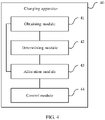
- FIG. 4 is a schematic structural diagram of a charging apparatus according to an embodiment of this application.
- the charging apparatus 40 may be disposed in a charging device, and the charging apparatus 40 may include an obtaining module 41, a determining module 42, an allocation module 43, and a control module 44.
- the charging apparatus 40 may be disposed in a charging device 900 shown in FIG. 6 .
- Functions of the obtaining module 41, the determining module 42, the allocation module 43, and the control module 44 may be implemented by a processor 910 in the charging device 900 shown in FIG. 6 .
- the obtaining module 41 is configured to obtain an in-position status of an adapter of the charging device and a usage status of the charging device.
- the determining module 42 is configured to: determine maximum output power of the charging device based on the in-position status of the adapter, determine reserved power of the charging device based on the usage status of the charging device, and determine available charging power of the charging device based on the maximum output power of the charging device and the reserved power of the charging device.
- the obtaining module 41 is further configured to obtain a connection status between a charging port of the charging device and an electronic device.
- the allocation module 43 is configured to allocate, based on priorities of charging ports, connected to electronic devices, of the charging device, the available charging power of the charging device to the charging ports, connected to the electronic devices, of the charging device.
- the control module 44 is configured to control the charging port, connected to the electronic device, of the charging device to charge the connected electronic device based on allocated power.
- the determining module 42 is specifically configured to: when the adapter is in position, determine that the maximum output power of the charging device is a sum of input power of the adapter and power provided by the charging device; and when the adapter is not in position, determine that the maximum output power of the charging device is the power provided by the charging device.
- the charging apparatus provided in the embodiment shown in FIG. 4 may be configured to perform the technical solution in the method embodiment shown in FIG. 1 of this application.
- FIG. 5 is a schematic structural diagram of a charging apparatus according to another embodiment of this application.
- an allocation module 43 may include a power range determining submodule 431 and a power allocation submodule 432, where
- the power range determining submodule 431 is further configured to: after the power allocation submodule 432 allocates the first charging power in the first power range to the highest-priority charging port, determine a second power range based on minimum power required by a second-highest-priority charging port in the charging ports, connected to the electronic devices, of the charging device, the available charging power of the charging device, the first charging power, and minimum power required by a charging port whose priority is lower than the second highest priority; and the power allocation submodule 432 is further configured to allocate second charging power in the second power range to the second-highest-priority charging port.
- the power range determining submodule 431 is further configured to: after the power allocation submodule 432 allocates the second charging power in the second power range to the second-highest-priority charging port, determine a third power range based on minimum power required by a lowest-priority charging port in the charging ports, connected to the electronic devices, of the charging device, the available charging power of the charging device, the first charging power, and the second charging power; and the power allocation submodule 432 is further configured to allocate third charging power in the third power range to the lowest-priority charging port.
- a control module 44 is further configured to: after an obtaining module 41 obtains a usage status of the charging device, and an abnormal event occurs on the charging device, control the charging device to stop charging the connected electronic device, where the abnormal event includes one or a combination of the following: An adapter of the charging device is not in position and a power level of the charging device is smaller than a predetermined power level threshold, the charging device is powered on or off, the adapter of the charging device is switched between an in-position state and a not-in-position state, and the electronic device connected to the charging device is switched between a connection state and a disconnection state.
- the charging apparatus 50 may be disposed in a charging device 900 shown in FIG. 6 .
- Functions of the obtaining module 41, a determining module 42, the allocation module 43, and the control module 44 may be implemented by a processor 910 in the charging device 900 shown in FIG. 6 .
- the charging apparatus 50 provided in the embodiment shown in FIG. 5 may be configured to perform the technical solutions in the method embodiments shown in FIG. 1 to FIG. 3 of this application.
- division into the foregoing modules of the charging apparatus shown in FIG. 4 and FIG. 5 is merely logical function division.
- all or some modules may be integrated into one physical entity, or may be physically separated.
- all of the modules may be implemented in a form of software invoked by a processing element or in a form of hardware.
- some of the modules may be implemented in a form of software invoked by a processing element, and some of the modules may be implemented in a form of hardware.
- the allocation module may be a separately disposed processing element, or may be integrated into a chip of a charging device, for example, a mobile power pack, for implementation. Implementations of other modules are similar to the implementation of the allocation module.
- modules may be integrated together, or may be implemented independently.
- steps in the foregoing methods or the foregoing modules can be implemented by using a hardware integrated logical circuit in a processor element, or by using instructions in a form of software.
- the foregoing modules may be configured as one or more integrated circuits for implementing the foregoing methods, for example, one or more application-specific integrated circuits (Application Specific Integrated Circuit, ASIC for short), one or more microprocessors (Digital Signal Processor, DSP for short), or one or more field programmable gate arrays (Field Programmable Gate Array, FPGA for short).
- ASIC Application Specific Integrated Circuit
- DSP Digital Signal Processor
- FPGA Field Programmable Gate Array
- these modules may be integrated together, and implemented in a form of a system-on-a-chip (System-On-a-Chip, SOC for short).
- FIG. 6 is a schematic structural diagram of a charging device according to an embodiment of this application.
- the charging device may include one or more processors, a memory, a plurality of applications, and one or more computer programs, where the one or more computer programs are stored in the memory, the one or more computer programs include instructions, and when the instructions are executed by the device, the device is enabled to perform the following steps:
- that the device is enabled to perform the step of determining maximum output power of the charging device based on the in-position status of the adapter includes:
- the device when the instructions are executed by the device, that the device is enabled to perform the step of allocating, based on priorities of charging ports, connected to electronic devices, of the charging device, the available charging power of the charging device to the charging ports, connected to the electronic devices, of the charging device includes:
- the device when the instructions are executed by the device, after the device enabled to perform the step of allocating first charging power in the first power range to the highest-priority charging port, the device further performs the following steps:
- the device when the instructions are executed by the device, after the device is enabled to perform the step of allocating second charging power in the second power range to the second-highest-priority charging port, the device further performs the following steps:
- the device when the instructions are executed by the device, after the device is enabled to perform the step of obtaining a usage status of the charging device, the device further performs the following step: after an abnormal event occurs on the charging device, controlling the charging device to stop charging the connected electronic device, where the abnormal event includes one or a combination of the following:
- the adapter of the charging device is not in position and a power level of the charging device is smaller than a predetermined power level threshold, the charging device is powered on or off, the adapter of the charging device is switched between an in-position state and a not-in-position state, and the electronic device connected to the charging device is switched between a connection state and a disconnection state.
- the charging device shown in FIG. 6 may be a terminal device, or may be a circuit device built into the terminal device.
- the device may be configured to perform functions/steps in the methods provided in the embodiments shown in FIG. 1 to FIG. 3 of this application.
- the charging device 900 includes a processor 910 and a transceiver 920.
- the charging device 900 may further include a memory 930.
- the processor 910, the transceiver 920, and the memory 930 may communicate with each other by using an internal connection path to transfer a control signal and/or a data signal.
- the memory 930 is configured to store a computer program.
- the processor 910 is configured to invoke the computer program from the memory 930 and run the computer program.
- the processor 910 and the memory 930 may be integrated into one processing apparatus, or more commonly, components that are independent of each other.
- the processor 910 is configured to execute program code stored in the memory 930 to implement the foregoing functions.
- the memory 930 may also be integrated into the processor 910, or may be independent of the processor 910.
- the charging device 900 may further include one or more of an input unit 960, a display unit 970, and the like.
- the display unit 970 may include a display screen.
- the charging device 900 may further include a battery 950.
- the charging device 900 shown in FIG. 6 can implement processes of the methods provided in the embodiments shown in FIG. 1 to FIG. 3 .
- Operations and/or functions of the modules in the charging device 900 are respectively for implementing corresponding procedures in the foregoing method embodiments.
- processor 910 in the charging device 900 shown in FIG. 6 may be a system-on-a-chip SOC, and the processor 910 may include a central processing unit (Central Processing Unit, CPU for short), may further include another type of processor, for example, an image processing unit (Graphics Processing Unit, GPU for short).
- CPU Central Processing Unit
- GPU Graphics Processing Unit
- processors or processing units in the processor 910 may cooperate to implement the previous method procedures, and software programs corresponding to the processors or processing units may be stored in the memory 930.
- the memory 930 may be a read-only memory (read-only memory, ROM), another type of static storage device that can store static information and an instruction, or a random access memory (random access memory, RAM) or another type of dynamic storage device that can store information and an instruction, or may be an electrically erasable programmable read-only memory (electrically erasable programmable read-only memory, EEPROM), a compact disc read-only memory (compact disc read-only memory, CD-ROM) or another compact disc storage, an optical disc storage (including a compact optical disc, a laser disc, an optical disc, a digital versatile optical disc, a Blu-ray disc, and the like), a magnetic disk storage medium or another magnetic storage device, any other medium that can be used to carry or store expected program code in a form of an instruction or a data structure and that can be accessed by a computer, or the like.
- ROM read-only memory
- RAM random access memory
- EEPROM electrically erasable programmable read-only memory
- An embodiment of this application further provides a computer-readable storage medium.
- the computer-readable storage medium stores a computer program.
- the computer program runs on a computer, the computer is enabled to perform the methods provided in the embodiments shown in FIG. 1 to FIG. 3 of this application.
- An embodiment of this application further provides a computer program product.
- the computer program product includes a computer program.
- the computer program runs on a computer, the computer is enabled to perform the methods provided in the embodiments shown in FIG. 1 to FIG. 3 in this application.
- At least one means one or more
- a plurality of means two or more than two.
- the term “and/or” describes an association relationship for describing associated objects and represents that three relationships may exist. For example, A and/or B may represent the following three cases: Only A exists, both A and B exist, and only B exists, where A and B may be singular or plural.
- the character “/” generally indicates an “or” relationship between the associated objects.
- At least one of the following” or a similar expression thereof indicates any combination of the following, including any combination of one or more of the following.
- At least one of a, b, and c may indicate a, b, c, a and b, a and c, b and c, or a, b, and c, where a, b, and c may be singular or plural.
- any function is implemented in a form of a software function unit and sold or used as an independent product
- the function may be stored in a computer-readable storage medium.
- the software product is stored in a storage medium, and includes several instructions for instructing a computer device (which may be a personal computer, a server, or a network device) to perform all or some of the steps of the methods described in the embodiments of this application.
- the foregoing storage medium includes: any medium that can store program code, such as a USB flash drive, a removable hard disk, a read-only memory (Read-Only Memory, ROM for short), a random access memory (Random Access Memory, RAM for short), a magnetic disk, or an optical disc.
- program code such as a USB flash drive, a removable hard disk, a read-only memory (Read-Only Memory, ROM for short), a random access memory (Random Access Memory, RAM for short), a magnetic disk, or an optical disc.
Landscapes
- Engineering & Computer Science (AREA)
- Power Engineering (AREA)
- Manufacturing & Machinery (AREA)
- Chemical & Material Sciences (AREA)
- Chemical Kinetics & Catalysis (AREA)
- Electrochemistry (AREA)
- General Chemical & Material Sciences (AREA)
- Charge And Discharge Circuits For Batteries Or The Like (AREA)
Abstract
Description
- This application claims priority to
Chinese Patent Application No. 202010042304.X, filed with the Chinese Patent Office on January 15, 2020 - This application relates to the field of artificial intelligence technologies, and in particular, to a charging method and apparatus and a charging device.
- A relatively powerful device with a charging function in the current market, for example, a mobile power pack, generally supports both wired external charging and wireless external charging at the same time. Wired external charging is to charge an electronic device through a USB-type charging port A (hereinafter referred to as a port A) or a USB-type charging port C (hereinafter referred to as a port C), and in addition, the port C supports charging of the device. How to effectively allocate power in various charging scenarios to bring better charging experience to a user is very important.
- In a related conventional technology, when a mobile power pack has multiple concurrent outputs, output power is generally allocated according to a fixed rule. For example, when a port A and a port C are simultaneously used for external charging, both the port A and the port C are used for external charging based on predefined power. As a result, external output power cannot be maximized, and charging efficiency is poor.
- This application provides a charging method and apparatus and a charging device, and this application further provides a computer-readable storage medium, to adjust charging power of each charging port of the charging device, so that external output power of the charging device is maximized.
- According to a first aspect, this application provides a charging method, including:
- obtaining an in-position status of an adapter of a charging device and a usage status of the charging device, where in this embodiment, the charging device may be a device with a charging function, for example, a mobile power pack; the in-position status of the adapter of the charging device may include: The adapter of the charging device is in position or the adapter of the charging device is not in position; that the adapter of the charging device is in position means that the adapter of the charging device is connected to a power supply, and the charging device charges the charging device by using the adapter; and that the adapter of the charging device is not in position means that the adapter of the charging device is not connected to a power supply;
- determining maximum output power of the charging device based on the in-position status of the adapter, and determining reserved power of the charging device based on the usage status of the charging device, where in this embodiment, the reserved power of the charging device is power reserved by the charging device for use by the charging device (for example, mobile Wi-Fi), the reserved power of the charging device may be determined based on the usage status of the charging device, and the usage status of the charging device may include a power-on state or standby state of the charging device;
- determining available charging power of the charging device based on the maximum output power of the charging device and the reserved power of the charging device, where, specifically, the available charging power of the charging device may be a difference between the maximum output power of the charging device and the reserved power of the charging device, that is, PRMNG = PMAX - PRSVD, where PRMNG is the available charging power of the charging device, and PRSVD is the reserved power of the charging device;
- obtaining a connection status between a charging port of the charging device and an electronic device, where the electronic device includes a device that is charged by using the charging device, for example, a device such as a smartphone, a smartwatch, a tablet computer, a smart wearable device, or a smart screen; specifically, the obtaining a connection status between a charging port of the charging device and an electronic device may be understood as obtaining whether the charging port of the charging device is connected to the electronic device;
- allocating, based on priorities of charging ports, connected to electronic devices, of the charging device of the charging device, the available charging power of the charging device to the charging ports, connected to the electronic devices, of the charging device; and
- controlling the charging port, connected to the electronic device, of the charging device to charge the connected electronic device based on allocated power.
- In the foregoing charging method, after the in-position status of the adapter of the charging device and the usage status of the charging device are obtained, the charging device may determine the maximum output power of the charging device based on the in-position status of the adapter, determine the reserved power of the charging device based on the usage status of the charging device, then, determine the available charging power of the charging device based on the maximum output power of the charging device and the reserved power of the charging device, next, obtain the connection status between the charging port of the charging device and the electronic device, allocate, based on the priorities of the charging ports, connected to the electronic devices, of the charging device, the available charging power of the charging device to the charging ports, connected to the electric devices, of the charging device, and finally, control the charging port, connected to the electronic device, of the charging device to charge the connected electronic device based on the allocated power. Therefore, charging power of each charging port can be adjusted based on the priority of each charging port of the charging device, so that external charging efficiency of the charging device is maximized, and charging efficiency of the charging device is improved.
- In a possible implementation, the determining maximum output power of the charging device based on the in-position status of the adapter includes:
- when the adapter is in position, determining that the maximum output power of the charging device is a sum of input power of the adapter and power provided by the charging device, that is, PMAX is equal to the input power of the adapter plus PBAT; and
- when the adapter is not in position, determining that the maximum output power of the charging device is the power provided by the charging device, that is, PMAX = PBAT.
- In a possible implementation, the allocating, based on priorities of charging ports, connected to electronic devices, of the charging device, the available charging power of the charging device to the charging ports, connected to the electronic devices, of the charging device includes:
- determining a first power range based on minimum power required by a highest-priority charging port in the charging ports, connected to the electronic devices, of the charging device, the available charging power of the charging device, and minimum power required by a charging port whose priority is lower than the highest priority; and
- allocating first charging power in the first power range to the highest-priority charging port.
- Specifically, the allocating first charging power in the first power range to the highest-priority charging port may be understood as: negotiating, in the first power range based on the highest-priority charging port, charging power between the charging device and the electronic device, to select a mutually supported maximum charging level, and allocating successfully negotiated power to the highest-priority charging port as the first charging power.
- In a possible implementation, after the allocating first charging power in the first power range to the highest-priority charging port, the method further includes:
- determining a second power range based on minimum power required by a second-highest-priority charging port in the charging ports, connected to the electronic devices, of the charging device, the available charging power of the charging device, the first charging power, and minimum power required by a charging port whose priority is lower than the second highest priority; and
- allocating second charging power in the second power range to the second-highest-priority charging port.
- Specifically, the allocating second charging power in the second power range to the second-highest-priority charging port may be understood as: negotiating, in the second power range based on the second-highest-priority charging port, charging power between the charging device and the electronic device, to select a mutually supported maximum charging level, and allocating successfully negotiated power to the second-highest-priority charging port as the second charging power.
- In a possible implementation, after the allocating second charging power in the second power range to the second-highest-priority charging port, the method further includes:
- determining a third power range based on minimum power required by a lowest-priority charging port in the charging ports, connected to the electronic devices, of the charging device, the available charging power of the charging device, the first charging power, and the second charging power; and
- allocating third charging power in the third power range to the lowest-priority charging port.
- Specifically, the allocating third charging power in the third power range to the lowest-priority charging port may be understood as: negotiating, in the third power range based on the lowest-priority charging port, charging power between the charging device and the electronic device, to select a mutually supported maximum charging level, and allocating successfully negotiated power to the lowest-priority charging port as the third charging power.
- In a possible implementation, after the obtaining a usage status of the charging device, the method further includes:
after an abnormal event occurs on the charging device, controlling the charging device to stop charging the connected electronic device, where the abnormal event includes one or a combination of the following: The adapter of the charging device is not in position and a power level of the charging device is smaller than a predetermined power level threshold, the charging device is powered on or off, the adapter of the charging device is switched between an in-position state and a not-in-position state, and the electronic device connected to the charging device is switched between a connection state and a disconnection state. The predetermined power level threshold may be customized during a specific implementation, and a value of the predetermined power level threshold is not limited in this embodiment. - According to a second aspect, an embodiment of this application provides a charging apparatus, disposed in a charging device, where the charging apparatus includes:
- an obtaining module, configured to obtain an in-position status of an adapter of the charging device and a usage status of the charging device;
- a determining module, configured to: determine maximum output power of the charging device based on the in-position status of the adapter, determine reserved power of the charging device based on the usage status of the charging device, and determine available charging power of the charging device based on the maximum output power of the charging device and the reserved power of the charging device, where
- the obtaining module is further configured to obtain a connection status between a charging port of the charging device and an electronic device;
- an allocation module, configured to allocate, based on priorities of charging ports, connected to electronic devices, of the charging device, the available charging power of the charging device to the charging ports, connected to the electronic devices, of the charging device; and
- a control module, configured to control the charging port, connected to the electronic device, of the charging device to charge the connected electronic device based on allocated power.
- In a possible implementation, the determining module is specifically configured to: when the adapter is in position, determine that the maximum output power of the charging device is a sum of input power of the adapter and power provided by the charging device; and when the adapter is not in position, determine that the maximum output power of the charging device is the power provided by the charging device.
- In a possible implementation, the allocation module includes:
- a power range determining submodule, configured to determine a first power range based on minimum power required by a highest-priority charging port in the charging ports, connected to the electronic devices, of the charging device, the available charging power of the charging device, and minimum power required by a charging port whose priority is lower than the highest priority; and
- a power allocation submodule, configured to allocate first charging power in the first power range to the highest-priority charging port.
- In a possible implementation, the power range determining submodule is further configured to: after the power allocation submodule allocates the first charging power in the first power range to the highest-priority charging port, determine a second power range based on minimum power required by a second-highest-priority charging port in the charging ports, connected to the electronic devices, of the charging device, the available charging power of the charging device, the first charging power, and minimum power required by a charging port whose priority is lower than the second highest priority; and
the power allocation submodule is further configured to allocate second charging power in the second power range to the second-highest-priority charging port. - In a possible implementation, the power range determining submodule is further configured to: after the power allocation submodule allocates the second charging power in the second power range to the second-highest-priority charging port, determine a third power range based on minimum power required by a lowest-priority charging port in the charging ports, connected to the electronic devices, of the charging device, the available charging power of the charging device, the first charging power, and the second charging power; and
the power allocation submodule is further configured to allocate third charging power in the third power range to the lowest-priority charging port. - In a possible implementation, the control module is further configured to: after the obtaining module obtains the usage status of the charging device, and an abnormal event occurs on the charging device, control the charging device to stop charging the connected electronic device, where the abnormal event includes one or a combination of the following: The adapter of the charging device is not in position and a power level of the charging device is smaller than a predetermined power level threshold, the charging device is powered on or off, the adapter of the charging device is switched between an in-position state and a not-in-position state, and the electronic device connected to the charging device is switched between a connection state and a disconnection state.
- According to a third aspect, an embodiment of this application provides a charging device, including:
- one or more processors, a memory, a plurality of applications, and one or more computer programs, where the one or more computer programs are stored in the memory, the one or more computer programs include instructions, and when the instructions are executed by the device, the device is enabled to perform the following steps:
- obtaining an in-position status of an adapter of the charging device and a usage status of the charging device;
- determining maximum output power of the charging device based on the in-position status of the adapter, and determining reserved power of the charging device based on the usage status of the charging device;
- determining available charging power of the charging device based on the maximum output power of the charging device and the reserved power of the charging device;
- obtaining a connection status between a charging port of the charging device and an electronic device;
- allocating, based on priorities of charging ports, connected to electronic devices, of the charging device, the available charging power of the charging device to the charging ports, connected to the electronic devices, of the charging device; and
- controlling the charging port, connected to the electronic device, of the charging device to charge the connected electronic device based on allocated power.
- In a possible implementation, when the instructions are executed by the device, that the device is enabled to perform the step of determining maximum output power of the charging device based on the in-position status of the adapter includes:
- when the adapter is in position, determining that the maximum output power of the charging device is a sum of input power of the adapter and power provided by the charging device; and
- when the adapter is not in position, determining that the maximum output power of the charging device is the power provided by the charging device.
- In a possible implementation, when the instructions are executed by the device, that the device is enabled to perform the step of allocating, based on priorities of charging ports, connected to electronic devices, of the charging device, the available charging power of the charging device to the charging ports, connected to the electronic devices, of the charging device includes:
- determining a first power range based on minimum power required by a highest-priority charging port in the charging ports, connected to the electronic devices, of the charging device, the available charging power of the charging device, and minimum power required by a charging port whose priority is lower than the highest priority; and
- allocating first charging power in the first power range to the highest-priority charging port.
- In a possible implementation, when the instructions are executed by the device, after the device is enabled to perform the step of allocating first charging power in the first power range to the highest-priority charging port, the device further performs the following steps:
- determining a second power range based on minimum power required by a second-highest-priority charging port in the charging ports, connected to the electronic devices, of the charging device, the available charging power of the charging device, the first charging power, and minimum power required by a charging port whose priority is lower than the second highest priority; and
- allocating second charging power in the second power range to the second-highest-priority charging port.
- In a possible implementation, when the instructions are executed by the device, after the device is enabled to perform the step of allocating second charging power in the second power range to the second-highest-priority charging port, the device further performs the following steps:
- determining a third power range based on minimum power required by a lowest-priority charging port in the charging ports, connected to the electronic devices, of the charging device, the available charging power of the charging device, the first charging power, and the second charging power; and
- allocating third charging power in the third power range to the lowest-priority charging port.
- In a possible implementation, when the instructions are executed by the device, after the device is enabled to perform the step of obtaining a usage status of the charging device, the device further performs the following step:
after an abnormal event occurs on the charging device, controlling the charging device to stop charging the connected electronic device, where the abnormal event includes one or a combination of the following: The adapter of the charging device is not in position and a power level of the charging device is smaller than a predetermined power level threshold, the charging device is powered on or off, the adapter of the charging device is switched between an in-position state and a not-in-position state, and the electronic device connected to the charging device is switched between a connection state and a disconnection state. - It should be understood that, technical solutions in the second to the third aspects of this application are consistent with technical solutions in the first aspect. Beneficial effects achieved by the various aspects and corresponding feasible implementations are similar, and details are not described again.
- According to a fourth aspect, this application provides a computer-readable storage medium, wherethe computer-readable storage medium stores a computer program, and when the computer program runs on a computer, the computer is enabled to perform the method according to the first aspect.
- According to a fifth aspect, this application provides a computer program, where when the computer program is executed by a computer, the computer program is used to perform the method according to the first aspect.
- In a possible design, all or some of the programs in the fifth aspect may be stored in a storage medium encapsulated with a processor, or some or all of the programs may be stored in a memory that is not encapsulated with a processor.
-
-
FIG. 1 is a flowchart of a charging method according to an embodiment of this application; -
FIG. 2 is a flowchart of a charging method according to another embodiment of this application; -
FIG. 3 is a flowchart of a charging method according to another embodiment of this application; -
FIG. 4 is a schematic structural diagram of a charging apparatus according to an embodiment of this application; -
FIG. 5 is a schematic structural diagram of a charging apparatus according to another embodiment of this application; and -
FIG. 6 is a schematic structural diagram of a charging device according to an embodiment of this application. - Terms used in implementations of this application are merely intended to explain specific embodiments of this application, and are not intended to limit this application.
- In a related conventional technology, when a charging device (for example, a mobile power pack) has multiple concurrent outputs, output power is generally allocated according to a fixed rule. For example, when a USB-type A and a USB-type C are simultaneously used for power supply, both the port A and the port C are used for external charging based on predefined power. As a result, external output power cannot be maximized, and charging efficiency is poor.
- The charging device is a device with a charging function.
- Therefore, this application provides a charging method, to adjust charging power of each charging port based on a priority of each charging port of the charging device, so that the external output power of the charging device is maximized.
-
FIG. 1 is a flowchart of a charging method according to an embodiment of this application. As shown inFIG. 1 , the charging method includes the following steps. - Step 101: Obtain an in-position status of an adapter of a charging device and a usage status of the charging device.
- In this embodiment, the charging device may be a device with a charging function, for example, a mobile power pack. The in-position status of the adapter of the charging device may include: The adapter of the charging device is in position or the adapter of the charging device is not in position; that the adapter of the charging device is in position means that the adapter of the charging device is connected to a power supply, and the charging device charges the charging device by using the adapter; and that the adapter of the charging device is not in position means that the adapter of the charging device is not connected to a power supply.
- Step 102: Determine maximum output power of the charging device based on the in-position status of the adapter, and determine reserved power of the charging device based on the usage status of the charging device.
- Specifically, determining the maximum output power of the charging device based on the in-position status of the adapter may be understood as:
- when the adapter is in position, determining that the maximum output power of the charging device is a sum of input power of the adapter and power provided by the charging device, that is, PMAX is equal to the input power of the adapter plus PBAT; and
- when the adapter is not in position, determining that the maximum output power of the charging device is the power provided by the charging device, that is, PMAX = PBAT,where
- PMAX is the maximum output power of the charging device, and PBAT is the power provided by the charging device.
- In this embodiment, the reserved power of the charging device is power reserved by the charging device for use by the charging device (for example, mobile Wi-Fi), the reserved power of the charging device may be determined based on the usage status of the charging device, and the usage status of the charging device may include a power-on state or standby state of the charging device.
- Step 103: Determine available charging power of the charging device based on the maximum output power of the charging device and the reserved power of the charging device.
- Specifically, the available charging power of the charging device may be a difference between the maximum output power of the charging device and the reserved power of the charging device, that is, PRMNG = PMAX - PRSVD, where PRMNG is the available charging power of the charging device, and PRSVD is the reserved power of the charging device.
- Step 104: Obtain a connection status between a charging port of the charging device and an electronic device.
- The electronic device includes a device that is charged by using the charging device, for example, a device such as a smartphone, a smartwatch, a tablet computer, a smart wearable device, or a smart screen.
- Specifically, obtaining the connection status between the charging port of the charging device and the electronic device may be understood as obtaining whether the charging port of the charging device is connected to the electronic device.
- Step 105: Allocate, based on priorities of charging ports, connected to electronic devices, of the charging device, the available charging power of the charging device to the charging ports, connected to the electronic devices, of the charging device.
- Step 106: Control the charging port, connected to the electronic device, of the charging device to charge the connected electronic device based on allocated power.
- In the foregoing charging method, after the in-position status of the adapter of the charging device and the usage status of the charging device are obtained, the charging device may determine the maximum output power of the charging device based on the in-position status of the adapter, determine the reserved power of the charging device based on the usage status of the charging device, then, determine the available charging power of the charging device based on the maximum output power of the charging device and the reserved power of the charging device, next, obtain the connection status between the charging port of the charging device and the electronic device, allocate, based on the priorities of the charging ports, connected to the electronic devices, of the charging device, the available charging power of the charging device to the charging ports, connected to the electric devices, of the charging device, and finally, control the charging port, connected to the electronic device, of the charging device to charge the connected electronic device based on the allocated power. Therefore, charging power of each charging port can be adjusted based on the priority of each charging port of the charging device, so that external charging efficiency of the charging device is maximized, and charging efficiency of the charging device is improved.
-
FIG. 2 is a flowchart of a charging method according to another embodiment of this application. As shown inFIG. 2 , in the embodiment shown inFIG. 1 of this application,step 105 may include the following steps. - Step 201: Determine a first power range based on minimum power required by a highest-priority charging port in the charging ports, connected to the electronic devices, of the charging device, the available charging power of the charging device, and minimum power required by a charging port whose priority is lower than the highest priority.
- Step 202: Allocate first charging power in the first power range to the highest-priority charging port.
- Specifically, allocating the first charging power in the first power range to the highest-priority charging port may be understood as: negotiating, in the first power range based on the highest-priority charging port, charging power between the charging device and the electronic device, to select a mutually supported maximum charging level, and allocating successfully negotiated power to the highest-priority charging port as the first charging power.
- Further, after
step 202, the method may further include the following steps: - Step 203: Determine a second power range based on minimum power required by a second-highest-priority charging port in the charging ports, connected to the electronic devices, of the charging device, the available charging power of the charging device, the first charging power, and minimum power required by a charging port whose priority is lower than the second highest priority.
- Step 204: Allocate second charging power in the second power range to the second-highest-priority charging port.
- Specifically, allocating the second charging power in the second power range to the second-highest-priority charging port may be understood as: negotiating, in the second power range based on the second-highest-priority charging port, charging power between the charging device and the electronic device, to select a mutually supported maximum charging level, and allocating successfully negotiated power to the second-highest-priority charging port as the second charging power.
- Further, after
step 204, the method may further include the following steps: - Step 205: Determine a third power range based on minimum power required by a lowest-priority charging port in the charging ports, connected to the electronic devices, of the charging device, the available charging power of the charging device, the first charging power, and the second charging power.
- Step 206: Allocate third charging power in the third power range to the lowest-priority charging port.
- Specifically, allocating the third charging power in the third power range to the lowest-priority charging port may be understood as: negotiating, in the third power range based on the lowest-priority charging port, charging power between the charging device and the electronic device, to select a mutually supported maximum charging level, and allocating successfully negotiated power to the lowest-priority charging port as the third charging power.
- In this embodiment, the charging device may include three charging ports: a port A, a port C, and a wireless charging port. Priorities of the three charging ports may be set based on a sequence of connecting the charging ports to electronic devices. For example, it is assumed that the port A is first connected to an electronic device. In other words, the port A is first accessed by an electronic device. The priority of the port A may be set to be the highest. Alternatively, the priorities of the three charging ports may be preset. For example, it may be preset that the priority of the port C is the highest, the priority of the port A is the second highest, and the priority of the wireless charging port is the lowest. A priority setting rule of the charging ports of the charging device is not limited in this embodiment. The following uses preset priorities of the charging ports as an example for description.
- (1) When the adapter is in position, the charging device charges the charging device by using the port C, and the remaining port A and wireless charging port may be used for external charging. In this case, to ensure external charging efficiency of the charging device, if input power of the adapter does not meet maximum power required for external charging, power is preferentially obtained from a battery of the charging device to perform external charging. In this case, maximum output power of the charging device PMAX is equal to the input power of the adapter plus PBAT. After the maximum power required for external charging is subtracted from the maximum output power of the charging device, if there is remaining power, the battery of the charging device is charged by using the remaining power. When the adapter is in position, the port A is a highest-priority charging port, and the wireless charging port is a second-highest-priority charging port, and is also a charging port whose priority is lower than a highest priority. A manner in which the available charging power of the charging device is allocated to the charging ports of the charging device may be as follows:
- Maximum charging power supported by the port A is selected for the port A within a range of [PAMIN, (PRMNG - PWMIN)]; and
- Maximum charging power supported by the wireless charging port is selected for the wireless charging port within a range of [PWMIN, (PRMNG - PADST)], where
- PAMIN is minimum power required by the port A, PRMNG is the available charging power of the charging device, PWMIN is minimum power required by the wireless charging port, [PAMIN, (PRMNG - PWMIN)] is a first charging range, and PADST is finally allocated maximum charging power when the port A is used for external charging, namely, first charging power; and [PWMIN, (PRMNG - PADST)] is a second charging range, and when the wireless charging port is used for external charging, finally allocated maximum charging power is second charging power.
- For example, when the adapter is in position, the port A and the wireless charging port are used for external charging at the same time, and PBAT = 30.4 W. When power is allocated to the port A and the wireless charging port, to be compatible with a 5 V/1 A adapter, a specific power allocation manner may be shown in Table 1.
Table 1 The adapter is in position. (It is assumed that inputs of the adapter are 9 V/2 A, PBAT = 30.4 W, PRSVD = 2 W, and PRMNG = 28.4 W.) It is assumed that the port A has the highest priority and the wireless charging port has the second highest priority. External charging through the port A (supported charging levels: 5 V/4.5 A, 9 V 2 A, 5 V/2 A, and 5 V/1 A) External charging through the wireless charging port (supported charging levels: 15 W, 10 W, 7.5 W, and 5 W) Effective power (W) output by the charging device A predetermined rule (compatible with the 5 V/1 A adapter) 5 V/4.5 A 10W 32.5 A power allocation result according to an existing predetermined rule 5 V/4.5 A 10W 32.5 A power allocation result in this application 5 V/4.5 A Based on the power allocation manner in this application, the maximum charging power supported by the port A is selected within a range of [5, 28.4 + 18 - 22.5]. In other words, 15 W is selected in (15 W, 10 W, 7.5 W, and 5 W) as 37.5 The adapter is in position. (It is assumed that inputs of the adapter are 9 V/2 A, PBAT = 30.4 W, PRSVD = 2 W, and PRMNG = 28.4 W.) the maximum charging power. - It can be learned from Table 1 that, when power is allocated according to the existing predetermined rule, the effective power output by the charging device is 32.5 W, but after the power is allocated based on the method provided in this application, the effective power output by the charging device is 37.5 W. Therefore, charging power of each charging port is adjusted based on a priority of the charging port of the charging device, so that external charging efficiency of the charging device is maximized, and charging efficiency of the charging device is improved.
- (2) When the adapter is not in position, external charging ports of the charging device include the port A, the port C, and the wireless charging port. When the adapter is not in position, the port C is a highest-priority charging port, the port A is a second-highest-priority charging port, the wireless charging port is a lowest-priority charging port, the port A and the wireless charging port are charging ports whose priorities are lower than the highest priority, and the wireless charging port is a charging port whose priority is lower than the second highest priority. A manner in which the available charging power of the charging device is allocated to the charging ports of the charging device may be as follows:
- Maximum charging power supported by the port C is selected for the port C within a range of [PCMIN, (PRMNG - PWMIN - PAMIN)];
- maximum charging power supported by the port A is selected for the port A within a range of [PAMIN, (PRMNG - PCDST - PWMIN)]; and
- a maximum charging level supported by the wireless charging port is selected for the wireless charging port within a range of [PWMIN, (PRMNG -PCDST - PADST)], where
- PCMIN is minimum power required by the port C, PAMIN is minimum power required by the port A, PWMIN is minimum power required by the wireless charging port, PRMNG is the available charging power of the charging device, [PCMIN, (PRMNG - PWMIN - PAMIN)] is a first charging range, and PCDST is finally allocated maximum charging power when the port C is used for external charging, namely, first charging power; [PAMIN, (PRMNG - PCDST - PWMIN)] is a second charging range, and PADST is finally allocated maximum charging power when the port A is used for external charging, namely, second charging power; and [PWMIN, (PRMNG - PCDST - PADST)] is a third charging range, and when the wireless charging port is used for external charging, finally allocated maximum charging power is third charging power.
- For example, when the adapter is not in position, the port C and the port A are used for external charging at the same time, and to be compatible with a 5 V/1 A adapter in the market, a specific power allocation manner may be shown in Table 2.
Table 2 The adapter is not in position. (PBAT = 30.4 W, PRSVD = 2 W, and PRMNG = 28.4 W) It is assumed that the port C is preferred. External charging through the port C (supported charging levels: 9 V 2 A, 5 V/2 A, and 5 V/1 A) External charging through the port A (supported charging levels: 5 V/4.5 A, 9 V 2 A, 5 V/2 A, and 5 V/1 A) Effective power (W) output by the charging device A predetermined rule (it is considered that the port C is preferred, and maximum power is negotiated for the port C.) 9 V/2 A 5 V/2 A 28 A power allocation result according to an existing predetermined rule (an electronic device connected to the port C does not support fast charging.) 5 V/2 A 5 V/2 A 20 A power allocation result in this application (the electronic device connected to the port C does not support fast charging.) 5 V/2 A Based on the power allocation manner in this application, maximum charging power supported by the port A is selected within a range of [5, 28.4 - 10]. In other words, 9 V/2 A, namely, 18 W, is selected as the maximum charging power in (5 V/4.5 A, 9 V 2 A, 5 V/2 A, 5 V/1 A). 28 - It can be learned from Table 2 that, according to an existing predetermined rule, the effective power that can be output by the charging device is 28 W. However, if the electronic device connected to the port C does not support fast charging, after power is allocated according to the existing predetermined rule, effective power actually output by the charging device is 20 W. However, after the power is allocated based on the method provided in this application, the effective power output by the charging device can still reach 28 W. Therefore, charging power of each charging port is adjusted based on a priority of each charging port of the charging device, so that external charging efficiency of the charging device is maximized, and charging efficiency of the charging device is improved.
-
FIG. 3 is a flowchart of a charging method according to another embodiment of this application. As shown inFIG. 3 , in the embodiment shown inFIG. 1 of this application, afterstep 101, the method may further include the following step:
Step 301: After an abnormal event occurs on the charging device, controlling the charging device to stop charging the connected electronic device, where the abnormal event includes one or a combination of the following: The adapter of the charging device is not in position and a power level of the charging device is smaller than a predetermined power level threshold, the charging device is powered on or off, the adapter of the charging device is switched between an in-position state and a not-in-position state, and the electronic device connected to the charging device is switched between a connection state and a disconnection state. - The predetermined power level threshold may be customized during a specific implementation, and a value of the predetermined power level threshold is not limited in this embodiment.
- It may be understood that some or all of the steps or operations in the foregoing embodiments are merely examples. In the embodiments of this application, other operations or variations of various operations may be further performed. In addition, the steps may be performed in a sequence different from that presented in the foregoing embodiments, and not all the operations in the foregoing embodiments are necessarily performed.
-
FIG. 4 is a schematic structural diagram of a charging apparatus according to an embodiment of this application. As shown inFIG. 4 , the chargingapparatus 40 may be disposed in a charging device, and the chargingapparatus 40 may include an obtainingmodule 41, a determiningmodule 42, anallocation module 43, and acontrol module 44. It should be understood that the chargingapparatus 40 may be disposed in acharging device 900 shown inFIG. 6 . Functions of the obtainingmodule 41, the determiningmodule 42, theallocation module 43, and thecontrol module 44 may be implemented by aprocessor 910 in thecharging device 900 shown inFIG. 6 . - The obtaining
module 41 is configured to obtain an in-position status of an adapter of the charging device and a usage status of the charging device. - The determining
module 42 is configured to: determine maximum output power of the charging device based on the in-position status of the adapter, determine reserved power of the charging device based on the usage status of the charging device, and determine available charging power of the charging device based on the maximum output power of the charging device and the reserved power of the charging device. - The obtaining
module 41 is further configured to obtain a connection status between a charging port of the charging device and an electronic device. - The
allocation module 43 is configured to allocate, based on priorities of charging ports, connected to electronic devices, of the charging device, the available charging power of the charging device to the charging ports, connected to the electronic devices, of the charging device. - The
control module 44 is configured to control the charging port, connected to the electronic device, of the charging device to charge the connected electronic device based on allocated power. - In a possible implementation, the determining
module 42 is specifically configured to: when the adapter is in position, determine that the maximum output power of the charging device is a sum of input power of the adapter and power provided by the charging device; and when the adapter is not in position, determine that the maximum output power of the charging device is the power provided by the charging device. - The charging apparatus provided in the embodiment shown in
FIG. 4 may be configured to perform the technical solution in the method embodiment shown inFIG. 1 of this application. For an implementation principle and a technical effect of the charging apparatus, further refer to related descriptions in the method embodiment. -
FIG. 5 is a schematic structural diagram of a charging apparatus according to another embodiment of this application. A difference between the chargingapparatus 40 shown inFIG. 4 and the chargingapparatus 50 shown inFIG. 5 lies in that anallocation module 43 may include a powerrange determining submodule 431 and apower allocation submodule 432, where - the power
range determining submodule 431 is configured to determine a first power range based on minimum power required by a highest-priority charging port in charging ports, connected to electronic devices, of charging device, available charging power of the charging device, and minimum power required by a charging port whose priority is lower than a highest priority; and - the
power allocation submodule 432 is configured to allocate first charging power in the first power range to the highest-priority charging port. - In a possible implementation, the power
range determining submodule 431 is further configured to: after thepower allocation submodule 432 allocates the first charging power in the first power range to the highest-priority charging port, determine a second power range based on minimum power required by a second-highest-priority charging port in the charging ports, connected to the electronic devices, of the charging device, the available charging power of the charging device, the first charging power, and minimum power required by a charging port whose priority is lower than the second highest priority; and
thepower allocation submodule 432 is further configured to allocate second charging power in the second power range to the second-highest-priority charging port. - In a possible implementation, the power
range determining submodule 431 is further configured to: after thepower allocation submodule 432 allocates the second charging power in the second power range to the second-highest-priority charging port, determine a third power range based on minimum power required by a lowest-priority charging port in the charging ports, connected to the electronic devices, of the charging device, the available charging power of the charging device, the first charging power, and the second charging power; and
thepower allocation submodule 432 is further configured to allocate third charging power in the third power range to the lowest-priority charging port. - In a possible implementation, a
control module 44 is further configured to: after an obtainingmodule 41 obtains a usage status of the charging device, and an abnormal event occurs on the charging device, control the charging device to stop charging the connected electronic device, where the abnormal event includes one or a combination of the following: An adapter of the charging device is not in position and a power level of the charging device is smaller than a predetermined power level threshold, the charging device is powered on or off, the adapter of the charging device is switched between an in-position state and a not-in-position state, and the electronic device connected to the charging device is switched between a connection state and a disconnection state. - It should be understood that the charging
apparatus 50 may be disposed in acharging device 900 shown inFIG. 6 . Functions of the obtainingmodule 41, a determiningmodule 42, theallocation module 43, and thecontrol module 44 may be implemented by aprocessor 910 in thecharging device 900 shown inFIG. 6 . - The charging
apparatus 50 provided in the embodiment shown inFIG. 5 may be configured to perform the technical solutions in the method embodiments shown inFIG. 1 to FIG. 3 of this application. For an implementation principle and a technical effect of the charging apparatus, further refer to related descriptions in the method embodiments. - It should be understood that division into the foregoing modules of the charging apparatus shown in
FIG. 4 andFIG. 5 is merely logical function division. In an actual implementation, all or some modules may be integrated into one physical entity, or may be physically separated. In addition, all of the modules may be implemented in a form of software invoked by a processing element or in a form of hardware. Alternatively, some of the modules may be implemented in a form of software invoked by a processing element, and some of the modules may be implemented in a form of hardware. For example, the allocation module may be a separately disposed processing element, or may be integrated into a chip of a charging device, for example, a mobile power pack, for implementation. Implementations of other modules are similar to the implementation of the allocation module. In addition, all or some of these modules may be integrated together, or may be implemented independently. In an implementation process, steps in the foregoing methods or the foregoing modules can be implemented by using a hardware integrated logical circuit in a processor element, or by using instructions in a form of software. - For example, the foregoing modules may be configured as one or more integrated circuits for implementing the foregoing methods, for example, one or more application-specific integrated circuits (Application Specific Integrated Circuit, ASIC for short), one or more microprocessors (Digital Signal Processor, DSP for short), or one or more field programmable gate arrays (Field Programmable Gate Array, FPGA for short). For another example, these modules may be integrated together, and implemented in a form of a system-on-a-chip (System-On-a-Chip, SOC for short).
-
FIG. 6 is a schematic structural diagram of a charging device according to an embodiment of this application. The charging device may include one or more processors, a memory, a plurality of applications, and one or more computer programs, where the one or more computer programs are stored in the memory, the one or more computer programs include instructions, and when the instructions are executed by the device, the device is enabled to perform the following steps: - obtaining an in-position status of an adapter of the charging device and a usage status of the charging device;
- determining maximum output power of the charging device based on the in-position status of the adapter, and determining reserved power of the charging device based on the usage status of the charging device;
- determining available charging power of the charging device based on the maximum output power of the charging device and the reserved power of the charging device;
- obtaining a connection status between a charging port of the charging device and an electronic device;
- allocating, based on priorities of charging ports, connected to electronic devices, of the charging device, the available charging power of the charging device to the charging ports, connected to the electronic devices, of the charging device; and
- controlling the charging port, connected to the electronic device, of the charging device to charge the connected electronic device based on allocated power.
- In a possible implementation, when the instructions are executed by the device, that the device is enabled to perform the step of determining maximum output power of the charging device based on the in-position status of the adapter includes:
- when the adapter is in position, determining that the maximum output power of the charging device is a sum of input power of the adapter and power provided by the charging device; and
- when the adapter is not in position, determining that the maximum output power of the charging device is the power provided by the charging device.
- In a possible implementation, when the instructions are executed by the device, that the device is enabled to perform the step of allocating, based on priorities of charging ports, connected to electronic devices, of the charging device, the available charging power of the charging device to the charging ports, connected to the electronic devices, of the charging device includes:
- determining a first power range based on minimum power required by a highest-priority charging port in the charging ports, connected to the electronic devices, of the charging device, the available charging power of the charging device, and minimum power required by a charging port whose priority is lower than the highest priority; and
- allocating first charging power in the first power range to the highest-priority charging port.
- In a possible implementation, when the instructions are executed by the device, after the device enabled to perform the step of allocating first charging power in the first power range to the highest-priority charging port, the device further performs the following steps:
- determining a second power range based on minimum power required by a second-highest-priority charging port in the charging ports, connected to the electronic devices, of the charging device, the available charging power of the charging device, the first charging power, and minimum power required by a charging port whose priority is lower than the second highest priority; and
- allocating second charging power in the second power range to the second-highest-priority charging port.
- In a possible implementation, when the instructions are executed by the device, after the device is enabled to perform the step of allocating second charging power in the second power range to the second-highest-priority charging port, the device further performs the following steps:
- determining a third power range based on minimum power required by a lowest-priority charging port in the charging ports, connected to the electronic devices, of the charging device, the available charging power of the charging device, the first charging power, and the second charging power; and
- allocating third charging power in the third power range to the lowest-priority charging port.
- In a possible implementation, when the instructions are executed by the device, after the device is enabled to perform the step of obtaining a usage status of the charging device, the device further performs the following step:
after an abnormal event occurs on the charging device, controlling the charging device to stop charging the connected electronic device, where the abnormal event includes one or a combination of the following: The adapter of the charging device is not in position and a power level of the charging device is smaller than a predetermined power level threshold, the charging device is powered on or off, the adapter of the charging device is switched between an in-position state and a not-in-position state, and the electronic device connected to the charging device is switched between a connection state and a disconnection state. - The charging device shown in
FIG. 6 may be a terminal device, or may be a circuit device built into the terminal device. The device may be configured to perform functions/steps in the methods provided in the embodiments shown inFIG. 1 to FIG. 3 of this application. - As shown in
FIG. 6 , the chargingdevice 900 includes aprocessor 910 and a transceiver 920. Optionally, the chargingdevice 900 may further include amemory 930. Theprocessor 910, the transceiver 920, and thememory 930 may communicate with each other by using an internal connection path to transfer a control signal and/or a data signal. Thememory 930 is configured to store a computer program. Theprocessor 910 is configured to invoke the computer program from thememory 930 and run the computer program. - The
processor 910 and thememory 930 may be integrated into one processing apparatus, or more commonly, components that are independent of each other. Theprocessor 910 is configured to execute program code stored in thememory 930 to implement the foregoing functions. During a specific implementation, thememory 930 may also be integrated into theprocessor 910, or may be independent of theprocessor 910. - In addition, to improve a function of the
charging device 900, the chargingdevice 900 may further include one or more of aninput unit 960, adisplay unit 970, and the like. Thedisplay unit 970 may include a display screen. - Optionally, the charging
device 900 may further include abattery 950. - It should be understood that the
charging device 900 shown inFIG. 6 can implement processes of the methods provided in the embodiments shown inFIG. 1 to FIG. 3 . Operations and/or functions of the modules in thecharging device 900 are respectively for implementing corresponding procedures in the foregoing method embodiments. For details, refer to the descriptions in the method embodiments shown inFIG. 1 to FIG. 3 . To avoid repetition, detailed descriptions are properly omitted herein. - It should be understood that the
processor 910 in thecharging device 900 shown inFIG. 6 may be a system-on-a-chip SOC, and theprocessor 910 may include a central processing unit (Central Processing Unit, CPU for short), may further include another type of processor, for example, an image processing unit (Graphics Processing Unit, GPU for short). - In conclusion, the processors or processing units in the
processor 910 may cooperate to implement the previous method procedures, and software programs corresponding to the processors or processing units may be stored in thememory 930. - The
memory 930 may be a read-only memory (read-only memory, ROM), another type of static storage device that can store static information and an instruction, or a random access memory (random access memory, RAM) or another type of dynamic storage device that can store information and an instruction, or may be an electrically erasable programmable read-only memory (electrically erasable programmable read-only memory, EEPROM), a compact disc read-only memory (compact disc read-only memory, CD-ROM) or another compact disc storage, an optical disc storage (including a compact optical disc, a laser disc, an optical disc, a digital versatile optical disc, a Blu-ray disc, and the like), a magnetic disk storage medium or another magnetic storage device, any other medium that can be used to carry or store expected program code in a form of an instruction or a data structure and that can be accessed by a computer, or the like. - An embodiment of this application further provides a computer-readable storage medium. The computer-readable storage medium stores a computer program. When the computer program runs on a computer, the computer is enabled to perform the methods provided in the embodiments shown in
FIG. 1 to FIG. 3 of this application. - An embodiment of this application further provides a computer program product. The computer program product includes a computer program. When the computer program runs on a computer, the computer is enabled to perform the methods provided in the embodiments shown in
FIG. 1 to FIG. 3 in this application. - In the embodiments of this application, "at least one" means one or more, and "a plurality of" means two or more than two. The term "and/or" describes an association relationship for describing associated objects and represents that three relationships may exist. For example, A and/or B may represent the following three cases: Only A exists, both A and B exist, and only B exists, where A and B may be singular or plural. The character "/" generally indicates an "or" relationship between the associated objects. "At least one of the following" or a similar expression thereof indicates any combination of the following, including any combination of one or more of the following. For example, at least one of a, b, and c may indicate a, b, c, a and b, a and c, b and c, or a, b, and c, where a, b, and c may be singular or plural.
- A person of ordinary skill in the art may be aware that units, algorithms, and steps described in the embodiments disclosed in this application can be implemented by electronic hardware or a combination of computer software and electronic hardware. Whether the functions are performed by hardware or software depends on particular applications and design constraint conditions of the technical solutions. A person skilled in the art may use different methods to implement the described functions for each particular application, but it should not be considered that the implementation goes beyond the scope of this application.
- It may be clearly understood by a person skilled in the art that, for the purpose of convenient and brief description, for a detailed working process of the foregoing system, apparatus, and unit, refer to a corresponding process in the foregoing method embodiments, and details are not described herein again.
- In the several embodiments provided in this application, if any function is implemented in a form of a software function unit and sold or used as an independent product, the function may be stored in a computer-readable storage medium. Based on such an understanding, the technical solutions of this application essentially, or the part contributing to the conventional technology, or some of the technical solutions may be implemented in a form of a software product. The software product is stored in a storage medium, and includes several instructions for instructing a computer device (which may be a personal computer, a server, or a network device) to perform all or some of the steps of the methods described in the embodiments of this application. The foregoing storage medium includes: any medium that can store program code, such as a USB flash drive, a removable hard disk, a read-only memory (Read-Only Memory, ROM for short), a random access memory (Random Access Memory, RAM for short), a magnetic disk, or an optical disc.
- The foregoing descriptions are merely specific implementations of this application. Any variation or replacement readily figured out by a person skilled in the art within the technical scope disclosed in this application shall fall within the protection scope of this application. The protection scope of this application shall be subject to the protection scope of the claims.
Claims (19)
- A charging method, comprising:obtaining an in-position status of an adapter of a charging device and a usage status of the charging device;determining maximum output power of the charging device based on the in-position status of the adapter, and determining reserved power of the charging device based on the usage status of the charging device;determining available charging power of the charging device based on the maximum output power of the charging device and the reserved power of the charging device;obtaining a connection status between a charging port of the charging device and an electronic device;allocating, based on priorities of charging ports, connected to electronic devices, of the charging device, the available charging power of the charging device to the charging ports, connected to the electronic devices, of the charging device; andcontrolling the charging port, connected to the electronic device, of the charging device to charge the connected electronic device based on allocated power.
- The method according to claim 1, wherein the determining maximum output power of the charging device based on the in-position status of the adapter comprises:when the adapter is in position, determining that the maximum output power of the charging device is a sum of input power of the adapter and power provided by the charging device; andwhen the adapter is not in position, determining that the maximum output power of the charging device is the power provided by the charging device.
- The method according to claim 1 or 2, wherein the allocating, based on priorities of charging ports, connected to electronic devices, of the charging device, the available charging power of the charging device to the charging ports, connected to the electronic devices, of the charging device comprises:determining a first power range based on minimum power required by a highest-priority charging port in the charging ports, connected to the electronic devices, of the charging device, the available charging power of the charging device, and minimum power required by a charging port whose priority is lower than the highest priority; andallocating first charging power in the first power range to the highest-priority charging port.
- The method according to claim 3, wherein after the allocating first charging power in the first power range to the highest-priority charging port, the method further comprises:determining a second power range based on minimum power required by a second-highest-priority charging port in the charging ports, connected to the electronic devices, of the charging device, the available charging power of the charging device, the first charging power, and minimum power required by a charging port whose priority is lower than the second highest priority; andallocating second charging power in the second power range to the second-highest-priority charging port.
- The method according to claim 4, wherein after the allocating second charging power in the second power range to the second-highest-priority charging port, the method further comprises:determining a third power range based on minimum power required by a lowest-priority charging port in the charging ports, connected to the electronic devices, of the charging device, the available charging power of the charging device, the first charging power, and the second charging power; andallocating third charging power in the third power range to the lowest-priority charging port.
- The method according to claim 1 or 2, wherein after the obtaining a usage status of the charging device, the method further comprises:
after an abnormal event occurs on the charging device, controlling the charging device to stop charging the connected electronic device, wherein the abnormal event comprises one or a combination of the following: The adapter of the charging device is not in position and a power level of the charging device is smaller than a predetermined power level threshold, the charging device is powered on or off, the adapter of the charging device is switched between an in-position state and a not-in-position state, and the electronic device connected to the charging device is switched between a connection state and a disconnection state. - A charging apparatus, disposed in a charging device, wherein the charging apparatus comprises:an obtaining module, configured to obtain an in-position status of an adapter of the charging device and a usage status of the charging device;a determining module, configured to: determine maximum output power of the charging device based on the in-position status of the adapter, determine reserved power of the charging device based on the usage status of the charging device, and determine available charging power of the charging device based on the maximum output power of the charging device and the reserved power of the charging device, whereinthe obtaining module is further configured to obtain a connection status between a charging port of the charging device and an electronic device;an allocation module, configured to allocate, based on priorities of charging ports, connected to electronic devices, of the charging device, the available charging power of the charging device to the charging ports, connected to the electronic devices, of the charging device; anda control module, configured to control the charging port, connected to the electronic device, of the charging device to charge the connected electronic device based on allocated power.
- The apparatus according to claim 7, wherein
the determining module is specifically configured to: when the adapter is in position, determine that the maximum output power of the charging device is a sum of input power of the adapter and power provided by the charging device; and when the adapter is not in position, determine that the maximum output power of the charging device is the power provided by the charging device. - The apparatus according to claim 7 or 8, wherein the allocation module comprises:a power range determining submodule, configured to determine a first power range based on minimum power required by a highest-priority charging port in the charging ports, connected to the electronic devices, of the charging device, the available charging power of the charging device, and minimum power required by a charging port whose priority is lower than the highest priority; anda power allocation submodule, configured to allocate first charging power in the first power range to the highest-priority charging port.
- The apparatus according to claim 9, whereinthe power range determining submodule is further configured to: after the power allocation submodule allocates the first charging power in the first power range to the highest-priority charging port, determine a second power range based on minimum power required by a second-highest-priority charging port in the charging ports, connected to the electronic devices, of the charging device of the charging device, the available charging power of the charging device, the first charging power, and minimum power required by a charging port whose priority is lower than the second highest priority; andthe power allocation submodule is further configured to allocate second charging power in the second power range to the second-highest-priority charging port.
- The apparatus according to claim 10, whereinthe power range determining submodule is further configured to: after the power allocation submodule allocates the second charging power in the second power range to the second-highest-priority charging port, determine a third power range based on minimum power required by a lowest-priority charging port in the charging ports, connected to the electronic devices, of the charging device of the charging device, the available charging power of the charging device, the first charging power, and the second charging power; andthe power allocation submodule is further configured to allocate third charging power in the third power range to the lowest-priority charging port.
- The apparatus according to claim 7 or 8, wherein
the control module is further configured to: after the obtaining module obtains the usage status of the charging device, and an abnormal event occurs on the charging device, control the charging device to stop charging the connected electronic device, wherein the abnormal event comprises one or a combination of the following: The adapter of the charging device is not in position and a power level of the charging device is smaller than a predetermined power level threshold, the charging device is powered on or off, the adapter of the charging device is switched between an in-position state and a not-in-position state, and the electronic device connected to the charging device is switched between a connection state and a disconnection state. - A charging device, comprising:
one or more processors, a memory, a plurality of applications, and one or more computer programs, wherein the one or more computer programs are stored in the memory, the one or more computer programs comprise instructions, and when the instructions are executed by the device, the device is enabled to perform the following steps:obtaining an in-position status of an adapter of the charging device and a usage status of the charging device;determining maximum output power of the charging device based on the in-position status of the adapter, and determining reserved power of the charging device based on the usage status of the charging device;determining available charging power of the charging device based on the maximum output power of the charging device and the reserved power of the charging device;obtaining a connection status between a charging port of the charging device and an electronic device;allocating, based on priorities of charging ports, connected to electronic devices, of the charging device, the available charging power of the charging device to the charging ports, connected to the electronic devices, of the charging device; andcontrolling the charging port, connected to the electronic device, of the charging device to charge the connected electronic device based on allocated power. - The device according to claim 13, wherein when the instructions are executed by the device, that the device is enabled to perform the step of determining maximum output power of the charging device based on the in-position status of the adapter comprises:when the adapter is in position, determining that the maximum output power of the charging device is a sum of input power of the adapter and power provided by the charging device; andwhen the adapter is not in position, determining that the maximum output power of the charging device is the power provided by the charging device.
- The device according to claim 13 or 14, wherein when the instructions are executed by the device, that the device is enabled to perform the step of allocating, based on priorities of charging ports, connected to electronic devices, of the charging device, the available charging power of the charging device to the charging ports, connected to the electronic devices, of the charging device comprises:determining a first power range based on minimum power required by a highest-priority charging port in the charging ports, connected to the electronic devices, of the charging device of the charging device, the available charging power of the charging device, and minimum power required by a charging port whose priority is lower than the highest priority; andallocating first charging power in the first power range to the highest-priority charging port.
- The device according to claim 15, wherein when the instructions are executed by the device, after the device is enabled to perform the step of allocating first charging power in the first power range to the charging port with the highest priority, the device further performs the following steps:determining a second power range based on minimum power required by a second-highest-priority charging port in the charging ports, connected to the electronic devices, of the charging device of the charging device, the available charging power of the charging device, the first charging power, and minimum power required by a charging port whose priority is lower than the second highest priority; andallocating second charging power in the second power range to the second-highest-priority charging port.
- The device according to claim 16, wherein when the instructions are executed by the device, after the device is enabled to perform the step of allocating second charging power in the second power range to the second-highest-priority charging port, the device further performs the following steps:determining a third power range based on minimum power required by a lowest-priority charging port in the charging ports, connected to the electronic devices, of the charging device of the charging device, the available charging power of the charging device, the first charging power, and the second charging power; andallocating third charging power in the third power range to the lowest-priority charging port.
- The device according to claim 13 or 14, wherein when the instructions are executed by the device, after the device is enabled to perform the step of obtaining a usage status of the charging device, the device further performs the following step:
after an abnormal event occurs on the charging device, controlling the charging device to stop charging the connected electronic device, wherein the abnormal event comprises one or a combination of the following: The adapter of the charging device is not in position and a power level of the charging device is smaller than a predetermined power level threshold, the charging device is powered on or off, the adapter of the charging device is switched between an in-position state and a not-in-position state, and the electronic device connected to the charging device is switched between a connection state and a disconnection state. - A computer-readable storage medium, wherein the computer-readable storage medium stores a computer program, and when the computer program runs on a computer, the computer is enabled to perform the method according to any one of claims 1 to 6.
Applications Claiming Priority (2)
| Application Number | Priority Date | Filing Date | Title |
|---|---|---|---|
| CN202010042304.XA CN111162584B (en) | 2020-01-15 | 2020-01-15 | Charging methods, devices and charging equipment |
| PCT/CN2020/128062 WO2021143322A1 (en) | 2020-01-15 | 2020-11-11 | Charging method and apparatus and charging device |
Publications (2)
| Publication Number | Publication Date |
|---|---|
| EP4068558A1 true EP4068558A1 (en) | 2022-10-05 |
| EP4068558A4 EP4068558A4 (en) | 2023-01-25 |
Family
ID=70563020
Family Applications (1)
| Application Number | Title | Priority Date | Filing Date |
|---|---|---|---|
| EP20914162.1A Pending EP4068558A4 (en) | 2020-01-15 | 2020-11-11 | CHARGING METHOD AND APPARATUS, AND CHARGING DEVICE |
Country Status (3)
| Country | Link |
|---|---|
| EP (1) | EP4068558A4 (en) |
| CN (1) | CN111162584B (en) |
| WO (1) | WO2021143322A1 (en) |
Families Citing this family (4)
| Publication number | Priority date | Publication date | Assignee | Title |
|---|---|---|---|---|
| CN111162584B (en) * | 2020-01-15 | 2023-10-10 | 华为技术有限公司 | Charging methods, devices and charging equipment |
| CN113595213B (en) * | 2021-09-03 | 2023-10-31 | 康舒科技股份有限公司 | power distribution device |
| CN115071479B (en) * | 2022-06-30 | 2025-08-01 | 三一汽车起重机械有限公司 | Charging control method, device, electronic equipment and charging control system |
| CN119922583B (en) * | 2024-12-30 | 2025-12-12 | 中国电子科技集团公司第五十二研究所 | Data management method of portable server based on wireless MESH ad hoc network |
Family Cites Families (16)
| Publication number | Priority date | Publication date | Assignee | Title |
|---|---|---|---|---|
| US20080028237A1 (en) * | 2006-07-26 | 2008-01-31 | Roadnarrows, Llc | Power Management Using Integrated Data and Power Interfaces |
| US8266456B2 (en) * | 2007-10-15 | 2012-09-11 | Apple Inc. | Supplying remaining available current to port in excess of bus standard limit |
| US20140091623A1 (en) * | 2012-09-28 | 2014-04-03 | Keith Shippy | Power share controller |
| KR102271730B1 (en) * | 2014-07-31 | 2021-07-02 | 삼성전자주식회사 | Charging control Method and Device |
| KR102320853B1 (en) * | 2014-09-02 | 2021-11-02 | 삼성전자 주식회사 | Electronic device, method for charging control of the electronic device, charging device, and method for providing power of the charging device |
| TWI536705B (en) * | 2014-10-09 | 2016-06-01 | 勝德國際研發股份有限公司 | Charging device |
| EP3283934A1 (en) * | 2015-05-14 | 2018-02-21 | Apple Inc. | Dynamic power sharing among multiple physical ports |
| US20160336745A1 (en) * | 2015-05-14 | 2016-11-17 | Apple Inc. | Dynamic power sharing among multiple physical ports |
| CN105553051B (en) * | 2016-02-29 | 2018-03-30 | 惠州祺瑞电工有限公司 | A kind of port management method of more mouthfuls of output dc sources |
| US20170373522A1 (en) * | 2016-06-23 | 2017-12-28 | Apple Inc. | Charging System |
| CN205882808U (en) * | 2016-07-01 | 2017-01-11 | Tcl通力电子(惠州)有限公司 | Multiport power supply output circuit and battery charging outfit |
| US10873206B2 (en) * | 2017-05-30 | 2020-12-22 | Schneider Electric It Corporation | System and method for power storage and distribution |
| US10620679B2 (en) * | 2017-09-01 | 2020-04-14 | Dell Products L.P. | Prioritizing supplying electrical power by a power storage adapter to connected devices |
| CN107706972A (en) * | 2017-09-30 | 2018-02-16 | 湖南海翼电子商务股份有限公司 | Power output control method, circuit and charging device for charging device |
| US11106260B2 (en) * | 2018-02-13 | 2021-08-31 | Microsoft Technology Licensing, Llc | Smart charging platform |
| CN111162584B (en) * | 2020-01-15 | 2023-10-10 | 华为技术有限公司 | Charging methods, devices and charging equipment |
-
2020
- 2020-01-15 CN CN202010042304.XA patent/CN111162584B/en active Active
- 2020-11-11 WO PCT/CN2020/128062 patent/WO2021143322A1/en not_active Ceased
- 2020-11-11 EP EP20914162.1A patent/EP4068558A4/en active Pending
Also Published As
| Publication number | Publication date |
|---|---|
| EP4068558A4 (en) | 2023-01-25 |
| CN111162584A (en) | 2020-05-15 |
| WO2021143322A1 (en) | 2021-07-22 |
| CN111162584B (en) | 2023-10-10 |
Similar Documents
| Publication | Publication Date | Title |
|---|---|---|
| EP4068558A1 (en) | Charging method and apparatus and charging device | |
| US9378536B2 (en) | CPU/GPU DCVS co-optimization for reducing power consumption in graphics frame processing | |
| KR102336856B1 (en) | Method for Controlling of Charging/Discharging Battery and Electronic Device Using the same | |
| US20160336745A1 (en) | Dynamic power sharing among multiple physical ports | |
| EP2939077B1 (en) | Power management system and method | |
| EP2629173A2 (en) | Method and system for powering usb device | |
| EP3283934A1 (en) | Dynamic power sharing among multiple physical ports | |
| US10461623B2 (en) | Voltage converter circuit, electronic device including the same and voltage conversion method | |
| US9450440B2 (en) | High capacity batteries with on-demand fast charge capability | |
| KR20150000675A (en) | Method for charging battery and an electronic device thereof | |
| US20180365425A1 (en) | Systems and methods for securely booting a system on chip via a virtual collated internal memory pool | |
| CN103869920B (en) | Circulating battery and management | |
| KR20160058561A (en) | Method for controlling different kind of battery cells and electronic device thereof | |
| KR20230073977A (en) | Role detection for usb-based charging | |
| WO2025007929A1 (en) | Data communication method and apparatus, and computer device and computer-readable storage medium | |
| CN107959072B (en) | A charging method, device, computer equipment and readable storage medium | |
| US9223379B2 (en) | Intelligent receive buffer management to optimize idle state residency | |
| WO2018072443A1 (en) | Charging method, apparatus, and data storage medium | |
| US20250202269A1 (en) | Reverse charging system and method, and related apparatus | |
| CN114142110A (en) | Battery control method, device, electronic equipment and storage medium | |
| CN110764905B (en) | Network model generation method and device, computer equipment and storage medium | |
| EP3258567B1 (en) | Self-loop detection method and apparatus for charging device | |
| EP4439320A1 (en) | Method and apparatus to improve performance and battery life for systems with discrete universal serial bus connector | |
| CN116169758A (en) | Output power adjustment method and charger | |
| EP4462242A1 (en) | Method for adjusting specification parameter of ssd and related product |
Legal Events
| Date | Code | Title | Description |
|---|---|---|---|
| STAA | Information on the status of an ep patent application or granted ep patent |
Free format text: STATUS: THE INTERNATIONAL PUBLICATION HAS BEEN MADE |
|
| PUAI | Public reference made under article 153(3) epc to a published international application that has entered the european phase |
Free format text: ORIGINAL CODE: 0009012 |
|
| STAA | Information on the status of an ep patent application or granted ep patent |
Free format text: STATUS: REQUEST FOR EXAMINATION WAS MADE |
|
| 17P | Request for examination filed |
Effective date: 20220701 |
|
| AK | Designated contracting states |
Kind code of ref document: A1 Designated state(s): AL AT BE BG CH CY CZ DE DK EE ES FI FR GB GR HR HU IE IS IT LI LT LU LV MC MK MT NL NO PL PT RO RS SE SI SK SM TR |
|
| A4 | Supplementary search report drawn up and despatched |
Effective date: 20230102 |
|
| RIC1 | Information provided on ipc code assigned before grant |
Ipc: H01M 10/44 20060101ALI20221220BHEP Ipc: H02J 7/34 20060101ALI20221220BHEP Ipc: H02J 7/00 20060101AFI20221220BHEP |
|
| DAV | Request for validation of the european patent (deleted) | ||
| DAX | Request for extension of the european patent (deleted) | ||
| STAA | Information on the status of an ep patent application or granted ep patent |
Free format text: STATUS: EXAMINATION IS IN PROGRESS |
|
| 17Q | First examination report despatched |
Effective date: 20241108 |