EP4068535B1 - Shaped collet for electrical stress grading in corona ignition systems - Google Patents
Shaped collet for electrical stress grading in corona ignition systems Download PDFInfo
- Publication number
- EP4068535B1 EP4068535B1 EP22175622.4A EP22175622A EP4068535B1 EP 4068535 B1 EP4068535 B1 EP 4068535B1 EP 22175622 A EP22175622 A EP 22175622A EP 4068535 B1 EP4068535 B1 EP 4068535B1
- Authority
- EP
- European Patent Office
- Prior art keywords
- insulator
- compliant
- high voltage
- ceramic
- collet
- Prior art date
- Legal status (The legal status is an assumption and is not a legal conclusion. Google has not performed a legal analysis and makes no representation as to the accuracy of the status listed.)
- Active
Links
Images

Classifications
-
- H—ELECTRICITY
- H01—ELECTRIC ELEMENTS
- H01T—SPARK GAPS; OVERVOLTAGE ARRESTERS USING SPARK GAPS; SPARKING PLUGS; CORONA DEVICES; GENERATING IONS TO BE INTRODUCED INTO NON-ENCLOSED GASES
- H01T19/00—Devices providing for corona discharge
-
- H—ELECTRICITY
- H01—ELECTRIC ELEMENTS
- H01T—SPARK GAPS; OVERVOLTAGE ARRESTERS USING SPARK GAPS; SPARKING PLUGS; CORONA DEVICES; GENERATING IONS TO BE INTRODUCED INTO NON-ENCLOSED GASES
- H01T13/00—Sparking plugs
- H01T13/50—Sparking plugs having means for ionisation of gap
-
- H—ELECTRICITY
- H01—ELECTRIC ELEMENTS
- H01T—SPARK GAPS; OVERVOLTAGE ARRESTERS USING SPARK GAPS; SPARKING PLUGS; CORONA DEVICES; GENERATING IONS TO BE INTRODUCED INTO NON-ENCLOSED GASES
- H01T13/00—Sparking plugs
- H01T13/20—Sparking plugs characterised by features of the electrodes or insulation
- H01T13/36—Sparking plugs characterised by features of the electrodes or insulation characterised by the joint between insulation and body, e.g. using cement
-
- H—ELECTRICITY
- H01—ELECTRIC ELEMENTS
- H01T—SPARK GAPS; OVERVOLTAGE ARRESTERS USING SPARK GAPS; SPARKING PLUGS; CORONA DEVICES; GENERATING IONS TO BE INTRODUCED INTO NON-ENCLOSED GASES
- H01T13/00—Sparking plugs
- H01T13/20—Sparking plugs characterised by features of the electrodes or insulation
- H01T13/38—Selection of materials for insulation
-
- H—ELECTRICITY
- H01—ELECTRIC ELEMENTS
- H01T—SPARK GAPS; OVERVOLTAGE ARRESTERS USING SPARK GAPS; SPARKING PLUGS; CORONA DEVICES; GENERATING IONS TO BE INTRODUCED INTO NON-ENCLOSED GASES
- H01T21/00—Apparatus or processes specially adapted for the manufacture or maintenance of spark gaps or sparking plugs
- H01T21/02—Apparatus or processes specially adapted for the manufacture or maintenance of spark gaps or sparking plugs of sparking plugs
-
- H—ELECTRICITY
- H01—ELECTRIC ELEMENTS
- H01T—SPARK GAPS; OVERVOLTAGE ARRESTERS USING SPARK GAPS; SPARKING PLUGS; CORONA DEVICES; GENERATING IONS TO BE INTRODUCED INTO NON-ENCLOSED GASES
- H01T13/00—Sparking plugs
- H01T13/40—Sparking plugs structurally combined with other devices
- H01T13/44—Sparking plugs structurally combined with other devices with transformers, e.g. for high-frequency ignition
Definitions
- This invention relates generally to corona ignition assemblies, and methods of manufacturing the corona ignition assemblies.
- Corona igniter assemblies for use in corona discharge ignition systems typically include an ignition coil assembly attached to a firing end assembly as a single component.
- the firing end assembly includes a central electrode charged to a high radio frequency voltage potential, creating a strong radio frequency electric field in a combustion chamber.
- the electric field causes a portion of a mixture of fuel and air in the combustion chamber to ionize thus facilitating combustion of the fuel-air mixture.
- the electric field is preferably controlled so that the fuel-air mixture maintains insulating properties and corona discharge occurs, also referred to as non-thermal plasma.
- the ionized portion of the fuel-air mixture forms a flame front which then becomes self-sustaining and combusts the remaining portion of the fuel-air mixture.
- the electric field is also preferably controlled so that the fuel-air mixture does not lose all insulating properties, which would create thermal plasma and an electric arc between the electrode and grounded cylinder walls, piston, or other portion of the igniter.
- the electric field is also controlled so that the corona discharge only occurs at the firing end and not along other portions of the corona igniter assembly.
- control is oftentimes difficult to achieve due to air gaps located between the components of the corona igniter assembly where unwanted corona discharge can occur.
- the metallic shielding and the different electrical properties between the insulator materials leads to an uneven electrical field and air gaps at the interfaces.
- the dissimilar coefficients of thermal expansion and creep between the insulator materials can also lead to air gaps at the interfaces.
- the electrical field tends to concentrate in those air gaps, leading to unwanted corona discharge.
- a corona igniter assembly comprising: a high voltage center electrode surrounded by a ceramic insulator and a high voltage insulator, said ceramic insulator being formed of a ceramic material and said high voltage insulator being formed of a material different from said ceramic material; a dielectric compliant insulator disposed between said ceramic insulator and said high voltage insulator; a layer extending between opposite edges and applied to at least one of said insulators; and a compliant collet formed of a partially resistive material covering one of said edges of said layer.
- the corona igniter assembly comprises a high voltage center electrode surrounded by a ceramic insulator and a high voltage insulator.
- the ceramic insulator is formed of a ceramic material
- the high voltage insulator is formed of a material different from the ceramic material.
- a dielectric compliant insulator is disposed between the ceramic insulator and the high voltage insulator.
- a layer of metal extends between opposite edges and is applied to at least one of the insulators.
- a compliant collet formed of a partially resistive material covers one of the edges of the layer of metal.
- Another aspect of the invention provides a method of manufacturing a corona igniter assembly.
- the method comprises the steps of: providing a ceramic insulator formed of a ceramic material, a high voltage insulator formed of a material different from the ceramic material, and a dielectric compliant insulator; and applying a layer of metal to at least one of the insulators.
- the method also includes disposing a high voltage center electrode in a bore of the ceramic insulator, a bore of the dielectric compliant insulator, and a bore of the high voltage insulator; and disposing a compliant collet formed of a partially resistive material over one of the edges of the layer of metal.
- a corona igniter assembly 20 for receiving a high radio frequency voltage and applying a radio frequency electric field in a combustion chamber containing a mixture of fuel and gas to provide a corona discharge is generally shown in Figure 1 .
- the corona igniter assembly 20 includes an ignition coil assembly 22, a firing end assembly 24, and a metal tube 26 surrounding and coupling the ignition coil assembly 22 to the firing end assembly 24.
- the corona igniter assembly 20 also includes a high voltage insulator 28 and at least one dielectric compliant insulator 30 each disposed between the ignition coil assembly 22 and a ceramic insulator 32 of the firing end assembly 24, inside of the metal tube 26.
- the ignition coil assembly 22 typically includes a plurality of windings (not shown) receiving energy from a power source (not shown) and generating the radio frequency high voltage electric field. According to the example embodiment shown in the Figures, the ignition coil assembly 22 extends along a center axis and includes a coil output member for transferring energy toward the firing end assembly 24.
- the firing end assembly 24 is a corona igniter, as shown in the Figures, for receiving the energy from the ignition coil assembly 22 and applying the radio frequency electric field in the combustion chamber to ignite the mixture of fuel and air.
- the corona igniter 24 includes an igniter central electrode 34, a metal shell 36, and the ceramic insulator 32.
- the ceramic insulator 32 includes an insulator bore receiving the igniter central electrode 34 and spacing the igniter central electrode 34 from the metal shell 36.
- the igniter central electrode 34 of the firing end assembly 24 extends longitudinally along the center axis from a terminal end to a firing end.
- An electrical terminal can be disposed on the terminal end, and a crown 38 is disposed on the firing end of the igniter central electrode 34.
- the crown 38 includes a plurality of branches extending radially outwardly relative to the center axis for applying the radio frequency electric field and forming a robust corona discharge.
- the ceramic insulator 32 also referred to as a firing end insulator 32, includes a bore receiving the igniter central electrode 34 and can be formed of several different ceramic materials which are capable of withstanding the operating conditions in the combustion chamber.
- the ceramic insulator 32 is formed of alumina.
- the material used to form the ceramic insulator 32 also has a high capacitance which drives the power requirements for the corona igniter assembly 20 and therefore should be kept as small as possible.
- the ceramic insulator 32 extends along the center axis from a ceramic end wall to a ceramic firing end adjacent the firing end of the igniter central electrode 34.
- the metal shell 36 surrounds the ceramic insulator 32, and the crown 38 is typically disposed outwardly of the ceramic firing end.
- the corona igniter assembly 20 also includes a high voltage central electrode 40 received in the bore of the ceramic insulator 32 and extending to the coil output member, as shown in Figures 2 and 3 .
- the electrical signal is carried by high voltage central electrode 40 (metallic rod).
- a brass pack can be disposed in the bore of the ceramic insulator 32 to electrically connect the high voltage central electrode 40 and the electrical terminal.
- the high voltage central electrode 40 is preferably able to float along the bore of the high voltage insulator 28.
- a spring or another axially complaint member can be disposed between the brass pack and the high voltage central electrode 40.
- the spring could be located between the high voltage central electrode 40 and the coil output member.
- the high voltage insulator 28 extends between an HV insulator upper wall coupled to a second dielectric compliant insulator 30 and an HV insulator lower wall coupled to the dielectric compliant insulator 30.
- the high voltage insulator 28 preferably fills the length and volume of the metal tube 26 located between the dielectric compliant insulators 30.
- the high voltage insulator 28 is typically formed of an insulating material which is different from the ceramic insulator 32 of the firing end assembly 24 and different from the at least one dielectric compliant insulator 30.
- the high voltage insulator 28 has a coefficient of thermal expansion (CLTE) which is greater than the coefficient of thermal expansion (CLTE) of the ceramic insulator 32.
- CLTE coefficient of thermal expansion
- This insulating material has electrical properties which keeps capacitance low and provides good efficiency.
- Table 1 lists preferred dielectric strength, dielectric constant, and dissipation factor ranges for the high voltage insulator 28; and Table 2 lists preferred thermal conductivity and coefficient of thermal expansion (CLTE) ranges for the high voltage insulator 28.
- the high voltage insulator 28 is formed of a fluoropolymer, such as polytetrafluoroethylene (PTFE).
- PTFE polytetrafluoroethylene
- the high voltage insulator 28 could alternatively be formed of other materials having electrical properties within the ranges of Table 1 and thermal properties within the ranges of Table 2.
- Table 1 Parameter Value U.M. Testing conditions Dielectric strength > 30 kV/mm -40°C, +150°C Dielectric constant ⁇ 2.5 1MHz; -40°C, +150°C Dissipation factor ⁇ 0.001 1MHz -40°C, +150°C Table 2 Thermal conductivity > 0.8 W/m/K 25°C CLTE ⁇ 35 ppm/K -40°C, +150°C
- the corona igniter assembly 20 includes three materials as electrical insulators between the central high voltage central electrode 40 and the external shielding (metal tube) 26.
- the dielectric compliant insulator 30 is compressed between the high voltage insulator 28 and the ceramic insulator 32.
- the dielectric compliant insulator 30 provides an axial compliance which compensates for the differences in coefficients of thermal expansion between the high voltage insulator 28, typically formed of fluoropolymer, and the ceramic insulator 32.
- the hardness of the dielectric compliant insulator 30 ranges from 40 to 80 (shore A).
- the compression force applied to the dielectric compliant insulator 30 is set by design to be within the elastic range of the chosen material, usually a rubber or silicone compound.
- the dielectric compliant insulator 30 is formed of rubber or a silicone compound, but could also be formed of silicone paste or injection molded silicone.
- the corona ignition system is realized by the coil producing the high frequency and high voltage electric field (E-field) and the firing end assembly 24 applying this E-field in the combustion chamber for fuel ignition.
- the E-field loads and unloads the capacitance between the high voltage central electrode 40 of the extension cable connecting the coil, the firing end assembly 24, and the external metal tube 26. This behavior implies that all the materials in the assembly impact the electrical performances of the system. If any layer or gap of air is left between the high voltage central electrode 40 and the external metal tube 26 (which is the closest ground plane), it is very likely that the corona inception voltage will be reached in those areas. If corona is formed within the igniter assembly 20, sensible performance losses and increased risk of discharge can be observed.
- the corona igniter assembly 20 can optionally include a semi-conductive sleeve 42 surrounding a portion of the high voltage central electrode 40 to dampen the peak electric field and fill air gaps along the high voltage central electrode 40.
- the high voltage central electrode 40 can be covered with the semiconductive sleeve 42.
- the semiconductive sleeve 42 typically extends axially from the upper HV connection (coil side or coil output member) to the brass pack inside the bore of the ceramic insulator 32.
- the semiconductive sleeve 42 can also extend continuously, uninterrupted, along the interfaces between the different insulators 28, 30, 32.
- the semiconductive sleeve 42 is formed of a rubber material with a conductive filler, such as graphite or another carbon-based material.
- a conductive filler such as graphite or another carbon-based material.
- silicone rubber can be used to form the semiconductive sleeve 42. It has been found that the semiconductive sleeve 42 behaves like a conductor at high voltage and high frequency (HV-HF). In one embodiment, the semiconductive sleeve 42 has an electrical conductivity higher than 10 -2 S/m.
- a layer 44 formed of metal is applied to an outer surface of at least one of the insulators (diameters of the insulating materials).
- the layer of metal applied to the insulators, ceramic in particular, allows a bond between a metallic ground plane and the insulator, avoiding any gap formation during the assembly or operation.
- the outer surface of the ceramic insulator metallized or coated with the metal layer 44 to inhibit (electrically) all the clearances between the insulator 32 itself and the metal shell 36.
- the ceramic insulator 32 generally adopted in spark plug technology, withstands the operating conditions in the combustion chamber but has very high capacitance that drives power requirements for the system and, therefore, has to be kept the smallest possible of the insulators, which can lead to the clearances.
- the termination of the metallization layer 44 which is usually very thin, is a sharp edge where the E-field concentrates to the point that it could be higher than the corona inception voltage or the dielectric strength of the surrounding materials.
- the height 44A of the sharp edge is shown in Figure 4 .
- a compliant semiconductive or metallic collet 46 or bead covers the metallization end to help reduce the electric field peak and the smooth electric field distribution.
- the compliant collet 46 is formed of a weakly-conductive or partially resistive material.
- the compliant collet 46 can be made of a single material, with homogeneous or inhomogeneous, isotropic or anisotropic electrical conductivity, which can or cannot be E-field dependent, or the compliant collet 46 can be made of layers of two or more different semiconductive or conductive materials, with the material closer to the sharp edge (metallization end) having the higher electrical conductivity.
- the averaged electrical conductivity of the compliant collet 46 must be higher than 10 -2 S/m.
- the averaged electrical conductivity of the material closer to the interface must be higher than 10 -2 S/m, while the averaged electrical conductivity of the other materials must be included in the 10 -6 to 10 -2 S/m range.
- the electric field peak at the termination of the metallization layer 44 is very high and usually higher than the corona inception voltage.
- the semiconductive or metallic (or weakly-conductive or partially resistive) compliant collet 46 smooths the electric field distribution at the interface of the sharp edge of the metal layer 44 and the surrounding area. In addition, the adhesion and overall compliancy at the interface is enhanced by the semiconductive or conductive compliant collet 46.
- the semiconductive or conductive compliant collet 46 is applied at the termination of the metallization layer 44 and it provides a bridge from the dissimilar insulating materials (ceramic insulator 32 and silicone rubber dielectric compliant insulator 30) to the plug shell 36 that acts as the primary ground plane, as shown in Figure 4 .
- the shape of the semiconductive or conductive compliant collet 46 is engineered in such a way that the effect of E-field concentration on the sharp edges and terminations is minimized. Simulations were adopted to optimize the round shape of the semiconductive or conductive compliant collet 46, which is typically formed of rubber.
- the compliant collet 46 also referred to as a semi-conductive ring, can be over-molded on the plug assembly with a specific, partially-compliant, tool 48, as shown in Figure 6 .
- the compliant collet 46 is formed of a semiconductive or conductive silicone rubber, and thus is a similar material to the silicone rubber insulating material of the dielectric compliant insulator 30.
- the compliant collet 46 and the dielectric compliant insulator 30 preferably have good adhesion properties and similar thermal expansion coefficients. These features help avoiding the generation of air gaps at the interface between the insulating materials and the ground plane.
- the mating angle ⁇ see Figures 4 and 10 , between the semiconductive or conductive compliant collet 46 and the ceramic insulator 32 has been optimized for the minimum peak electric field. For optimal performance, 45° ⁇ ⁇ ⁇ 90° and is only set by processability constraints.
- the mating angle ⁇ is the angle between a line perpendicular to the center axis of the corona igniter assembly 20 and a rounded top outer surface adjacent a flat inside surface of the compliant collet 46.
- the final shape of the semiconductive or conductive compliant collet 46 can be obtained through a high precision dispensing system.
- the adoption of a mold and injection process can ensure the highest control on the final geometry of the compliant collet 46 (See Figure 6 ).
- the high voltage insulator 28 formed of the fluoropolymer, or a thermosetting epoxy preferably fills the whole length of the extension located within the metal tube 26, from the ceramic insulator 32 and the dielectric compliant insulator 30 to the coil connection or coil output member.
- Such materials are adopted in alternative because their electrical properties keep the capacitance low, have good efficiency, or have compatible thermal expansion coefficients with the metal tube 26, i.e. extension shield.
- Another aspect of the invention includes forming the corona igniter assembly 20 including the components and the compliant collet 46 described above.
Landscapes
- Engineering & Computer Science (AREA)
- Manufacturing & Machinery (AREA)
- Physics & Mathematics (AREA)
- Plasma & Fusion (AREA)
- Spark Plugs (AREA)
- Ignition Installations For Internal Combustion Engines (AREA)
Description
- This application claims priority to
U.S. provisional patent application no. 62/613,518, filed January 4, 2018 U.S. utility patent application no. 16/239,224, filed January 3, 2019 - This invention relates generally to corona ignition assemblies, and methods of manufacturing the corona ignition assemblies.
- Corona igniter assemblies for use in corona discharge ignition systems typically include an ignition coil assembly attached to a firing end assembly as a single component. The firing end assembly includes a central electrode charged to a high radio frequency voltage potential, creating a strong radio frequency electric field in a combustion chamber. The electric field causes a portion of a mixture of fuel and air in the combustion chamber to ionize thus facilitating combustion of the fuel-air mixture. The electric field is preferably controlled so that the fuel-air mixture maintains insulating properties and corona discharge occurs, also referred to as non-thermal plasma. The ionized portion of the fuel-air mixture forms a flame front which then becomes self-sustaining and combusts the remaining portion of the fuel-air mixture. The electric field is also preferably controlled so that the fuel-air mixture does not lose all insulating properties, which would create thermal plasma and an electric arc between the electrode and grounded cylinder walls, piston, or other portion of the igniter.
- Ideally, the electric field is also controlled so that the corona discharge only occurs at the firing end and not along other portions of the corona igniter assembly. However, such control is oftentimes difficult to achieve due to air gaps located between the components of the corona igniter assembly where unwanted corona discharge can occur. For example, although the use of multiple insulators formed of several materials provides improved efficiency, robustness, and overall performance, the metallic shielding and the different electrical properties between the insulator materials leads to an uneven electrical field and air gaps at the interfaces. The dissimilar coefficients of thermal expansion and creep between the insulator materials can also lead to air gaps at the interfaces. During use of the corona igniter, the electrical field tends to concentrate in those air gaps, leading to unwanted corona discharge. Such corona discharge can cause material degradation and hinder the performance of the corona igniter assembly. Document
US2017/025824 discloses a corona igniter assembly comprising: a high voltage center electrode surrounded by a ceramic insulator and a high voltage insulator, said ceramic insulator being formed of a ceramic material and said high voltage insulator being formed of a material different from said ceramic material; a dielectric compliant insulator disposed between said ceramic insulator and said high voltage insulator; a layer extending between opposite edges and applied to at least one of said insulators; and a compliant collet formed of a partially resistive material covering one of said edges of said layer. - One aspect of the invention provides a corona igniter assembly. The corona igniter assembly comprises a high voltage center electrode surrounded by a ceramic insulator and a high voltage insulator. The ceramic insulator is formed of a ceramic material, and the high voltage insulator is formed of a material different from the ceramic material. A dielectric compliant insulator is disposed between the ceramic insulator and the high voltage insulator. A layer of metal extends between opposite edges and is applied to at least one of the insulators. A compliant collet formed of a partially resistive material covers one of the edges of the layer of metal.
- Another aspect of the invention provides a method of manufacturing a corona igniter assembly. The method comprises the steps of: providing a ceramic insulator formed of a ceramic material, a high voltage insulator formed of a material different from the ceramic material, and a dielectric compliant insulator; and applying a layer of metal to at least one of the insulators. The method also includes disposing a high voltage center electrode in a bore of the ceramic insulator, a bore of the dielectric compliant insulator, and a bore of the high voltage insulator; and disposing a compliant collet formed of a partially resistive material over one of the edges of the layer of metal.
- Other advantages of the present invention will be readily appreciated, as the same becomes better understood by reference to the following detailed description when considered in connection with the accompanying drawings wherein:
-
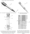
Figures 1 is a perspective view of a corona igniter assembly in an assembled position according to one exemplary embodiment of the invention; -
Figures 2-7 are sectional views of the corona igniter assembly ofFigure 1 showing a compliant collet according to an exemplary embodiment; -
Figure 8 illustrates a comparative assembly without the compliant collet; and -
Figures 9 and 10 illustrate the electric field within the assembly according to example embodiments. - A
corona igniter assembly 20 for receiving a high radio frequency voltage and applying a radio frequency electric field in a combustion chamber containing a mixture of fuel and gas to provide a corona discharge is generally shown inFigure 1 . Thecorona igniter assembly 20 includes an ignition coil assembly 22, afiring end assembly 24, and ametal tube 26 surrounding and coupling the ignition coil assembly 22 to thefiring end assembly 24. Thecorona igniter assembly 20 also includes ahigh voltage insulator 28 and at least one dielectriccompliant insulator 30 each disposed between the ignition coil assembly 22 and aceramic insulator 32 of thefiring end assembly 24, inside of themetal tube 26. - The ignition coil assembly 22 typically includes a plurality of windings (not shown) receiving energy from a power source (not shown) and generating the radio frequency high voltage electric field. According to the example embodiment shown in the Figures, the ignition coil assembly 22 extends along a center axis and includes a coil output member for transferring energy toward the
firing end assembly 24. - The
firing end assembly 24 is a corona igniter, as shown in the Figures, for receiving the energy from the ignition coil assembly 22 and applying the radio frequency electric field in the combustion chamber to ignite the mixture of fuel and air. The corona igniter 24 includes an ignitercentral electrode 34, ametal shell 36, and theceramic insulator 32. Theceramic insulator 32 includes an insulator bore receiving the ignitercentral electrode 34 and spacing the ignitercentral electrode 34 from themetal shell 36. - The igniter
central electrode 34 of thefiring end assembly 24 extends longitudinally along the center axis from a terminal end to a firing end. An electrical terminal can be disposed on the terminal end, and acrown 38 is disposed on the firing end of the ignitercentral electrode 34. Thecrown 38 includes a plurality of branches extending radially outwardly relative to the center axis for applying the radio frequency electric field and forming a robust corona discharge. - The
ceramic insulator 32, also referred to as afiring end insulator 32, includes a bore receiving the ignitercentral electrode 34 and can be formed of several different ceramic materials which are capable of withstanding the operating conditions in the combustion chamber. In one exemplary embodiment, theceramic insulator 32 is formed of alumina. The material used to form theceramic insulator 32 also has a high capacitance which drives the power requirements for thecorona igniter assembly 20 and therefore should be kept as small as possible. Theceramic insulator 32 extends along the center axis from a ceramic end wall to a ceramic firing end adjacent the firing end of the ignitercentral electrode 34. Themetal shell 36 surrounds theceramic insulator 32, and thecrown 38 is typically disposed outwardly of the ceramic firing end. - The
corona igniter assembly 20 also includes a high voltagecentral electrode 40 received in the bore of theceramic insulator 32 and extending to the coil output member, as shown inFigures 2 and 3 . The electrical signal is carried by high voltage central electrode 40 (metallic rod). - A brass pack can be disposed in the bore of the
ceramic insulator 32 to electrically connect the high voltagecentral electrode 40 and the electrical terminal. In addition, the high voltagecentral electrode 40 is preferably able to float along the bore of thehigh voltage insulator 28. Thus, a spring or another axially complaint member can be disposed between the brass pack and the high voltagecentral electrode 40. Alternatively, the spring could be located between the high voltagecentral electrode 40 and the coil output member. - In the example embodiments, the
high voltage insulator 28 extends between an HV insulator upper wall coupled to a second dielectriccompliant insulator 30 and an HV insulator lower wall coupled to the dielectriccompliant insulator 30. Thehigh voltage insulator 28 preferably fills the length and volume of themetal tube 26 located between the dielectriccompliant insulators 30. - The
high voltage insulator 28 is typically formed of an insulating material which is different from theceramic insulator 32 of thefiring end assembly 24 and different from the at least one dielectriccompliant insulator 30. Typically, thehigh voltage insulator 28 has a coefficient of thermal expansion (CLTE) which is greater than the coefficient of thermal expansion (CLTE) of theceramic insulator 32. This insulating material has electrical properties which keeps capacitance low and provides good efficiency. Table 1 lists preferred dielectric strength, dielectric constant, and dissipation factor ranges for thehigh voltage insulator 28; and Table 2 lists preferred thermal conductivity and coefficient of thermal expansion (CLTE) ranges for thehigh voltage insulator 28. In the exemplary embodiment, thehigh voltage insulator 28 is formed of a fluoropolymer, such as polytetrafluoroethylene (PTFE). Thehigh voltage insulator 28 could alternatively be formed of other materials having electrical properties within the ranges of Table 1 and thermal properties within the ranges of Table 2.Table 1 Parameter Value U.M. Testing conditions Dielectric strength > 30 kV/mm -40°C, +150°C Dielectric constant ≤ 2.5 1MHz; -40°C, +150°C Dissipation factor < 0.001 1MHz -40°C, +150°C Table 2 Thermal conductivity > 0.8 W/m/K 25°C CLTE < 35 ppm/K -40°C, +150°C - The
corona igniter assembly 20 includes three materials as electrical insulators between the central high voltagecentral electrode 40 and the external shielding (metal tube) 26. In the exemplary embodiments, the dielectriccompliant insulator 30 is compressed between thehigh voltage insulator 28 and theceramic insulator 32. The dielectriccompliant insulator 30 provides an axial compliance which compensates for the differences in coefficients of thermal expansion between thehigh voltage insulator 28, typically formed of fluoropolymer, and theceramic insulator 32. Preferably, the hardness of the dielectriccompliant insulator 30 ranges from 40 to 80 (shore A). The compression force applied to the dielectriccompliant insulator 30 is set by design to be within the elastic range of the chosen material, usually a rubber or silicone compound. Typically, the dielectriccompliant insulator 30 is formed of rubber or a silicone compound, but could also be formed of silicone paste or injection molded silicone. - As indicated above, the corona ignition system is realized by the coil producing the high frequency and high voltage electric field (E-field) and the firing
end assembly 24 applying this E-field in the combustion chamber for fuel ignition. The E-field loads and unloads the capacitance between the high voltagecentral electrode 40 of the extension cable connecting the coil, the firingend assembly 24, and theexternal metal tube 26. This behavior implies that all the materials in the assembly impact the electrical performances of the system. If any layer or gap of air is left between the high voltagecentral electrode 40 and the external metal tube 26 (which is the closest ground plane), it is very likely that the corona inception voltage will be reached in those areas. If corona is formed within theigniter assembly 20, sensible performance losses and increased risk of discharge can be observed. - It been found that the electric field concentrated at the interface of the
different insulators corona igniter assembly 20 can optionally include a semi-conductive sleeve 42 surrounding a portion of the high voltagecentral electrode 40 to dampen the peak electric field and fill air gaps along the high voltagecentral electrode 40. The high voltagecentral electrode 40 can be covered with the semiconductive sleeve 42. The semiconductive sleeve 42 typically extends axially from the upper HV connection (coil side or coil output member) to the brass pack inside the bore of theceramic insulator 32. - The semiconductive sleeve 42 can also extend continuously, uninterrupted, along the interfaces between the
different insulators - To avoid air gaps during assembly or operation of the
corona igniter assembly 20, alayer 44 formed of metal, also referred to as metallization, is applied to an outer surface of at least one of the insulators (diameters of the insulating materials). The layer of metal applied to the insulators, ceramic in particular, allows a bond between a metallic ground plane and the insulator, avoiding any gap formation during the assembly or operation. - The outer surface of the ceramic insulator metallized or coated with the
metal layer 44 to inhibit (electrically) all the clearances between theinsulator 32 itself and themetal shell 36. Theceramic insulator 32, generally adopted in spark plug technology, withstands the operating conditions in the combustion chamber but has very high capacitance that drives power requirements for the system and, therefore, has to be kept the smallest possible of the insulators, which can lead to the clearances. - As a drawback, the termination of the
metallization layer 44 which is usually very thin, is a sharp edge where the E-field concentrates to the point that it could be higher than the corona inception voltage or the dielectric strength of the surrounding materials. The height 44A of the sharp edge is shown inFigure 4 . - To reduce the electric field and smooth the electric field distribution at the sharp edge of the
metal layer 44, a compliant semiconductive ormetallic collet 46 or bead covers the metallization end to help reduce the electric field peak and the smooth electric field distribution. Thecompliant collet 46 is formed of a weakly-conductive or partially resistive material. Thecompliant collet 46 can be made of a single material, with homogeneous or inhomogeneous, isotropic or anisotropic electrical conductivity, which can or cannot be E-field dependent, or thecompliant collet 46 can be made of layers of two or more different semiconductive or conductive materials, with the material closer to the sharp edge (metallization end) having the higher electrical conductivity. In the case of the single material embodiment, the averaged electrical conductivity of thecompliant collet 46 must be higher than 10-2 S/m. In the case of thecompliant collet 46 being formed of several materials, the averaged electrical conductivity of the material closer to the interface must be higher than 10-2 S/m, while the averaged electrical conductivity of the other materials must be included in the 10-6 to 10-2 S/m range. - As stated above, the electric field peak at the termination of the
metallization layer 44 is very high and usually higher than the corona inception voltage. The semiconductive or metallic (or weakly-conductive or partially resistive)compliant collet 46 smooths the electric field distribution at the interface of the sharp edge of themetal layer 44 and the surrounding area. In addition, the adhesion and overall compliancy at the interface is enhanced by the semiconductive or conductivecompliant collet 46. - The semiconductive or conductive
compliant collet 46 is applied at the termination of themetallization layer 44 and it provides a bridge from the dissimilar insulating materials (ceramic insulator 32 and silicone rubber dielectric compliant insulator 30) to theplug shell 36 that acts as the primary ground plane, as shown inFigure 4 . The shape of the semiconductive or conductivecompliant collet 46 is engineered in such a way that the effect of E-field concentration on the sharp edges and terminations is minimized. Simulations were adopted to optimize the round shape of the semiconductive or conductivecompliant collet 46, which is typically formed of rubber. Thecompliant collet 46, also referred to as a semi-conductive ring, can be over-molded on the plug assembly with a specific, partially-compliant, tool 48, as shown inFigure 6 . - According to an example embodiment, the
compliant collet 46 is formed of a semiconductive or conductive silicone rubber, and thus is a similar material to the silicone rubber insulating material of the dielectriccompliant insulator 30. Thecompliant collet 46 and the dielectriccompliant insulator 30 preferably have good adhesion properties and similar thermal expansion coefficients. These features help avoiding the generation of air gaps at the interface between the insulating materials and the ground plane. - The mating angle β, see
Figures 4 and10 , between the semiconductive or conductivecompliant collet 46 and theceramic insulator 32 has been optimized for the minimum peak electric field. For optimal performance, 45°≤ β <90° and is only set by processability constraints. The mating angle β is the angle between a line perpendicular to the center axis of thecorona igniter assembly 20 and a rounded top outer surface adjacent a flat inside surface of thecompliant collet 46. - The final shape of the semiconductive or conductive
compliant collet 46 can be obtained through a high precision dispensing system. The adoption of a mold and injection process can ensure the highest control on the final geometry of the compliant collet 46 (SeeFigure 6 ). - The
high voltage insulator 28 formed of the fluoropolymer, or a thermosetting epoxy, preferably fills the whole length of the extension located within themetal tube 26, from theceramic insulator 32 and the dielectriccompliant insulator 30 to the coil connection or coil output member. Such materials are adopted in alternative because their electrical properties keep the capacitance low, have good efficiency, or have compatible thermal expansion coefficients with themetal tube 26, i.e. extension shield. - Another aspect of the invention includes forming the
corona igniter assembly 20 including the components and thecompliant collet 46 described above.
Claims (15)
- A corona igniter assembly (20) comprising:a high voltage center electrode (40) surrounded by a ceramic insulator (32) and a high voltage insulator (28), said ceramic insulator (32) being formed of a ceramic material and said high voltage insulator (28) being formed of a material different from said ceramic material;a dielectric compliant insulator (30) disposed between said ceramic insulator (32) and said high voltage insulator (28);a layer of metal (44) extending between opposite edges and applied to at least one of said insulators (28, 30, 32); anda compliant collet (46) formed of a partially resistive material covering one of said edges of said layer of metal (44).
- A corona igniter assembly (20) according to claim 1, wherein said compliant collet (46) is formed of silicone rubber.
- A corona igniter assembly (20) according to claim 1, wherein said one of said edges of said layer of metal (44) covered by said compliant collet (46) is sharp.
- A corona igniter assembly (20) according to claim 1, wherein said ceramic insulator (32) is formed of a material including alumina, said high voltage insulator (28) is formed of a material including polytetrafluoroethylene (PTFE) or epoxy having a coefficient of thermal expansion (CLTE) which is greater than a coefficient of thermal expansion (CLTE) of said ceramic insulator (32); and said dielectric compliant insulator (30) is formed of rubber or a material including silicone.
- A corona igniter assembly (20) according to claim 1, wherein said compliant collet (46) is formed of a single material with isotropic or anisotropic electrical conductivity, and said single material of said compliant collet (46) has an averaged electrical conductivity of higher than 10-2 S/m.
- A corona igniter assembly (20) according to claim 1, wherein said compliant collet (46) includes two semiconductive or conductive materials, a first one of said semiconductive or conductive materials is located closer to said one edge of said metal layer (44) and has a higher electrical conductivity that a second one of said semiconductive or conductive materials.
- A corona igniter assembly (20) according to claim 6, wherein an averaged electrical conductivity of said first one of said semiconductive or conductive materials is higher than 10-2 S/m, and an averaged electrical conductivity of said second one of said semiconductive or conductive materials is in a range of 10-6 to 10-2 S/m.
- A corona igniter assembly (20) according to claim 1, wherein said layer of metal (44) is disposed on said ceramic insulator (32).
- A corona igniter assembly (20) according to claim 1, wherein said compliant collet (46) and said ceramic insulator (32) present a mating angle therebetween which is at least 45° and less than 90°.
- A corona igniter assembly (20) according to claim 9, wherein said compliant collet (46) is disposed between said layer of metal (44) along said ceramic insulator (32) and said dielectric compliant member (30).
- A corona igniter assembly (20) according to claim 10, wherein said dielectric compliant member (30) and said compliant collet (46) are disposed between said high voltage insulator (28) and said ceramic insulator (32).
- A corona igniter assembly (20) according to claim 1 including an igniter central electrode (34) surrounded by said ceramic insulator (32) and a metal shell (36) surrounding said ceramic insulator (32); said igniter central electrode (34) extending longitudinally along a center axis from a terminal end to a firing end and including a crown (38) disposed on said firing end; and the crown (38) including a plurality of branches extending radially outwardly relative to said center axis.
- A corona igniter assembly (20) according to claim 1, wherein said high voltage insulator (28) is formed of a material having a dielectric strength of greater than 30 kV/mm, a dielectric constant of not greater than 2.5, a dissipation factor of less than 0.001, a thermal conductivity of greater than 0.8 W/mK at 25°C and a coefficient of thermal expansion (CLTE) of less than 35 ppm/K at temperatures ranging from -40°C to 150°C.
- A corona igniter assembly (20) according to claim 1, wherein said corona igniter assembly (20) further includes:an ignition coil assembly (22) coupled to said high voltage center electrode (40);a firing end assembly including an igniter central electrode (34) coupled to said high voltage center electrode (40);said firing end assembly including said ceramic insulator (32) surrounding said igniter central electrode (34) and a metal shell (36) surrounding said ceramic insulator (32);said igniter central electrode (34) extending longitudinally along a center axis from a terminal end to a firing end and including a crown (38) disposed on said firing end, said crown (38) including a plurality of branches extending radially outwardly relative to said center axis;said ceramic insulator (32) being formed of a material including alumina;said high voltage insulator (28) being formed of polytetrafluoroethylene (PTFE) or thermosetting epoxy;said dielectric compliant insulator (30) being formed of rubber or a material including silicone;said dielectric compliant insulator (30) being compressed between said high voltage insulator (28) and said ceramic insulator (32);a sleeve (42) formed of a material having an electrical conductivity higher than 10-2 S/m being disposed around said high voltage center electrode (40);a second dielectric compliant insulator (30) disposed between said high voltage insulator (28) and said ignition coil assembly (22);said layer of metal (44) is disposed along said ceramic insulator (32);said one edge of said layer of metal (44) being covered by said compliant collet (46) includes a sharp edge;said compliant collet (46) is disposed between said layer of metal (44) along said ceramic insulator (32) and said dielectric compliant member (30);said compliant collet (46) is formed of silicone rubber; andsaid compliant collet (46) and said ceramic insulator (32) present a mating angle therebetween which is at least 45° and less than 90°.
- A method of manufacturing a corona igniter assembly (20) comprising the steps of:providing a ceramic insulator (32) formed of a ceramic material, a high voltage insulator (28) formed of a material different from the ceramic material, and a dielectric compliant insulator (30);applying a layer of metal (44) to at least one of the insulators (28, 30, 32);disposing a high voltage center electrode (40) in a bore of the ceramic insulator (32), a bore of the dielectric compliant insulator (30), and a bore of the high voltage insulator (28); anddisposing a compliant collet (46) formed of a partially resistive material over one of the edges of the layer of metal (44).
Applications Claiming Priority (4)
| Application Number | Priority Date | Filing Date | Title |
|---|---|---|---|
| US201862613518P | 2018-01-04 | 2018-01-04 | |
| US16/239,224 US10879677B2 (en) | 2018-01-04 | 2019-01-03 | Shaped collet for electrical stress grading in corona ignition systems |
| PCT/US2019/012244 WO2019136192A1 (en) | 2018-01-04 | 2019-01-04 | Shaped collet for electrical stress grading in corona ignition systems |
| EP19702143.9A EP3735725B1 (en) | 2018-01-04 | 2019-01-04 | Shaped collet for electrical stress grading in corona ignition systems |
Related Parent Applications (2)
| Application Number | Title | Priority Date | Filing Date |
|---|---|---|---|
| EP19702143.9A Division EP3735725B1 (en) | 2018-01-04 | 2019-01-04 | Shaped collet for electrical stress grading in corona ignition systems |
| EP19702143.9A Division-Into EP3735725B1 (en) | 2018-01-04 | 2019-01-04 | Shaped collet for electrical stress grading in corona ignition systems |
Publications (2)
| Publication Number | Publication Date |
|---|---|
| EP4068535A1 EP4068535A1 (en) | 2022-10-05 |
| EP4068535B1 true EP4068535B1 (en) | 2024-04-17 |
Family
ID=67140209
Family Applications (2)
| Application Number | Title | Priority Date | Filing Date |
|---|---|---|---|
| EP22175622.4A Active EP4068535B1 (en) | 2018-01-04 | 2019-01-04 | Shaped collet for electrical stress grading in corona ignition systems |
| EP19702143.9A Active EP3735725B1 (en) | 2018-01-04 | 2019-01-04 | Shaped collet for electrical stress grading in corona ignition systems |
Family Applications After (1)
| Application Number | Title | Priority Date | Filing Date |
|---|---|---|---|
| EP19702143.9A Active EP3735725B1 (en) | 2018-01-04 | 2019-01-04 | Shaped collet for electrical stress grading in corona ignition systems |
Country Status (4)
| Country | Link |
|---|---|
| US (1) | US10879677B2 (en) |
| EP (2) | EP4068535B1 (en) |
| CN (1) | CN111656628B (en) |
| WO (1) | WO2019136192A1 (en) |
Family Cites Families (18)
| Publication number | Priority date | Publication date | Assignee | Title |
|---|---|---|---|---|
| US2902747A (en) * | 1959-09-08 | Reiter | ||
| US3883762A (en) * | 1974-06-17 | 1975-05-13 | Bendix Corp | Electrical discharge device comprising an insulator body having an electrically semi-conducting coating formed thereon |
| CH624509A5 (en) * | 1980-05-30 | 1981-07-31 | Espada Anstalt | |
| DE3782152D1 (en) * | 1986-11-29 | 1992-11-12 | Klaus Kalwar | METHOD FOR PRODUCING A CORONAL ELECTRODE AND CORONEL ELECTRODE PRODUCED BY THIS METHOD. |
| FR2881281B1 (en) * | 2005-01-26 | 2011-04-22 | Renault Sas | PLASMA GENERATION CANDLE |
| DE102009059649B4 (en) * | 2009-12-19 | 2011-11-24 | Borgwarner Beru Systems Gmbh | HF ignition device |
| DE102010022334B3 (en) | 2010-06-01 | 2011-12-01 | Borgwarner Beru Systems Gmbh | HF ignition device |
| FR2965984B1 (en) | 2010-10-12 | 2012-10-12 | Renault Sa | PREVENTION AGAINST A SHORT CIRCUIT OF THE RF CANDLE |
| DE102010055570B3 (en) | 2010-12-21 | 2012-03-15 | Borgwarner Beru Systems Gmbh | Fuel ignition device for internal combustion engine, has coil tapered to insulator body and wrapped on coil body, where coil body comprises tapered portion, which is wrapped to insulator body by turning coil |
| EP2659557B2 (en) * | 2010-12-29 | 2019-01-16 | Federal-Mogul Ignition Company | Corona igniter having improved gap control |
| DE102012108251B4 (en) * | 2011-10-21 | 2017-12-07 | Borgwarner Ludwigsburg Gmbh | Corona ignition device |
| DE102012111172B4 (en) | 2012-11-20 | 2016-01-28 | Borgwarner Ludwigsburg Gmbh | Corona ignition device |
| DE102013110246B4 (en) | 2013-09-17 | 2017-03-09 | Borgwarner Ludwigsburg Gmbh | Corona ignition device |
| DE102014111897B4 (en) * | 2013-10-31 | 2020-06-25 | Borgwarner Ludwigsburg Gmbh | Ignition device for igniting fuel-air mixtures in a combustion chamber of an internal combustion engine by means of a corona discharge |
| DE102014111684B3 (en) * | 2014-08-15 | 2015-10-01 | Borgwarner Ludwigsburg Gmbh | Koronazündeinrichtung |
| US9755405B2 (en) * | 2015-03-26 | 2017-09-05 | Federal-Mogul Llc | Corona suppression at the high voltage joint through introduction of a semi-conductive sleeve between the central electrode and the dissimilar insulating materials |
| DE102015120254B4 (en) | 2015-11-23 | 2019-11-28 | Borgwarner Ludwigsburg Gmbh | Corona ignition device and method for its production |
| US10211605B2 (en) * | 2016-01-22 | 2019-02-19 | Tenneco Inc. | Corona igniter with hermetic combustion seal on insulator inner diameter |
-
2019
- 2019-01-03 US US16/239,224 patent/US10879677B2/en active Active
- 2019-01-04 EP EP22175622.4A patent/EP4068535B1/en active Active
- 2019-01-04 WO PCT/US2019/012244 patent/WO2019136192A1/en not_active Ceased
- 2019-01-04 EP EP19702143.9A patent/EP3735725B1/en active Active
- 2019-01-04 CN CN201980009654.1A patent/CN111656628B/en active Active
Also Published As
| Publication number | Publication date |
|---|---|
| US10879677B2 (en) | 2020-12-29 |
| EP3735725A1 (en) | 2020-11-11 |
| WO2019136192A1 (en) | 2019-07-11 |
| CN111656628B (en) | 2022-07-12 |
| CN111656628A (en) | 2020-09-11 |
| EP4068535A1 (en) | 2022-10-05 |
| US20190214796A1 (en) | 2019-07-11 |
| EP3735725B1 (en) | 2022-07-06 |
Similar Documents
| Publication | Publication Date | Title |
|---|---|---|
| EP3275059B1 (en) | Corona suppression at the high voltage joint through introduction of a semi-conductive sleeve between the central electrode and the dissimilar insulating materials | |
| CN103210556B (en) | Corona igniter with improved corona control | |
| KR101904517B1 (en) | Corona igniter including temperature control features | |
| JP2018120867A (en) | Corona ignition device with improved electrical performance | |
| KR101868424B1 (en) | Corona igniter having shaped insulator | |
| US9787064B2 (en) | Corona ignition with hermetic combustion seal | |
| JP2018514905A5 (en) | ||
| EP3353864B1 (en) | Air-free cap end design for corona ignition system | |
| KR20130139901A (en) | Corona igniter having improved gap control | |
| CN113597653A (en) | Vacuum capacitor | |
| EP3735725B1 (en) | Shaped collet for electrical stress grading in corona ignition systems | |
| US10008831B2 (en) | Corona suppression at materials interface through gluing of the components | |
| CN108666870B (en) | Spark plug | |
| CN113412564B (en) | Corona ignition assembly including a high voltage connection and method of making a corona ignition assembly |
Legal Events
| Date | Code | Title | Description |
|---|---|---|---|
| PUAI | Public reference made under article 153(3) epc to a published international application that has entered the european phase |
Free format text: ORIGINAL CODE: 0009012 |
|
| STAA | Information on the status of an ep patent application or granted ep patent |
Free format text: STATUS: THE APPLICATION HAS BEEN PUBLISHED |
|
| AC | Divisional application: reference to earlier application |
Ref document number: 3735725 Country of ref document: EP Kind code of ref document: P |
|
| AK | Designated contracting states |
Kind code of ref document: A1 Designated state(s): AL AT BE BG CH CY CZ DE DK EE ES FI FR GB GR HR HU IE IS IT LI LT LU LV MC MK MT NL NO PL PT RO RS SE SI SK SM TR |
|
| STAA | Information on the status of an ep patent application or granted ep patent |
Free format text: STATUS: REQUEST FOR EXAMINATION WAS MADE |
|
| 17P | Request for examination filed |
Effective date: 20230322 |
|
| RBV | Designated contracting states (corrected) |
Designated state(s): AL AT BE BG CH CY CZ DE DK EE ES FI FR GB GR HR HU IE IS IT LI LT LU LV MC MK MT NL NO PL PT RO RS SE SI SK SM TR |
|
| P01 | Opt-out of the competence of the unified patent court (upc) registered |
Effective date: 20230528 |
|
| GRAP | Despatch of communication of intention to grant a patent |
Free format text: ORIGINAL CODE: EPIDOSNIGR1 |
|
| STAA | Information on the status of an ep patent application or granted ep patent |
Free format text: STATUS: GRANT OF PATENT IS INTENDED |
|
| RIC1 | Information provided on ipc code assigned before grant |
Ipc: H01T 13/44 20060101ALN20240108BHEP Ipc: H01T 21/02 20060101ALI20240108BHEP Ipc: H01T 13/50 20060101ALI20240108BHEP Ipc: H01T 13/38 20060101AFI20240108BHEP |
|
| INTG | Intention to grant announced |
Effective date: 20240122 |
|
| GRAS | Grant fee paid |
Free format text: ORIGINAL CODE: EPIDOSNIGR3 |
|
| GRAA | (expected) grant |
Free format text: ORIGINAL CODE: 0009210 |
|
| STAA | Information on the status of an ep patent application or granted ep patent |
Free format text: STATUS: THE PATENT HAS BEEN GRANTED |
|
| AC | Divisional application: reference to earlier application |
Ref document number: 3735725 Country of ref document: EP Kind code of ref document: P |
|
| AK | Designated contracting states |
Kind code of ref document: B1 Designated state(s): AL AT BE BG CH CY CZ DE DK EE ES FI FR GB GR HR HU IE IS IT LI LT LU LV MC MK MT NL NO PL PT RO RS SE SI SK SM TR |
|
| REG | Reference to a national code |
Ref country code: GB Ref legal event code: FG4D |
|
| REG | Reference to a national code |
Ref country code: CH Ref legal event code: EP |
|
| REG | Reference to a national code |
Ref country code: IE Ref legal event code: FG4D Ref country code: DE Ref legal event code: R096 Ref document number: 602019050703 Country of ref document: DE |
|
| REG | Reference to a national code |
Ref country code: LT Ref legal event code: MG9D |
|
| REG | Reference to a national code |
Ref country code: NL Ref legal event code: MP Effective date: 20240417 |
|
| REG | Reference to a national code |
Ref country code: AT Ref legal event code: MK05 Ref document number: 1678188 Country of ref document: AT Kind code of ref document: T Effective date: 20240417 |
|
| PG25 | Lapsed in a contracting state [announced via postgrant information from national office to epo] |
Ref country code: NL Free format text: LAPSE BECAUSE OF FAILURE TO SUBMIT A TRANSLATION OF THE DESCRIPTION OR TO PAY THE FEE WITHIN THE PRESCRIBED TIME-LIMIT Effective date: 20240417 |
|
| PG25 | Lapsed in a contracting state [announced via postgrant information from national office to epo] |
Ref country code: NL Free format text: LAPSE BECAUSE OF FAILURE TO SUBMIT A TRANSLATION OF THE DESCRIPTION OR TO PAY THE FEE WITHIN THE PRESCRIBED TIME-LIMIT Effective date: 20240417 |
|
| PG25 | Lapsed in a contracting state [announced via postgrant information from national office to epo] |
Ref country code: IS Free format text: LAPSE BECAUSE OF FAILURE TO SUBMIT A TRANSLATION OF THE DESCRIPTION OR TO PAY THE FEE WITHIN THE PRESCRIBED TIME-LIMIT Effective date: 20240817 |
|
| PG25 | Lapsed in a contracting state [announced via postgrant information from national office to epo] |
Ref country code: BG Free format text: LAPSE BECAUSE OF FAILURE TO SUBMIT A TRANSLATION OF THE DESCRIPTION OR TO PAY THE FEE WITHIN THE PRESCRIBED TIME-LIMIT Effective date: 20240417 |
|
| PG25 | Lapsed in a contracting state [announced via postgrant information from national office to epo] |
Ref country code: HR Free format text: LAPSE BECAUSE OF FAILURE TO SUBMIT A TRANSLATION OF THE DESCRIPTION OR TO PAY THE FEE WITHIN THE PRESCRIBED TIME-LIMIT Effective date: 20240417 Ref country code: FI Free format text: LAPSE BECAUSE OF FAILURE TO SUBMIT A TRANSLATION OF THE DESCRIPTION OR TO PAY THE FEE WITHIN THE PRESCRIBED TIME-LIMIT Effective date: 20240417 |
|
| PG25 | Lapsed in a contracting state [announced via postgrant information from national office to epo] |
Ref country code: GR Free format text: LAPSE BECAUSE OF FAILURE TO SUBMIT A TRANSLATION OF THE DESCRIPTION OR TO PAY THE FEE WITHIN THE PRESCRIBED TIME-LIMIT Effective date: 20240718 |
|
| PG25 | Lapsed in a contracting state [announced via postgrant information from national office to epo] |
Ref country code: PT Free format text: LAPSE BECAUSE OF FAILURE TO SUBMIT A TRANSLATION OF THE DESCRIPTION OR TO PAY THE FEE WITHIN THE PRESCRIBED TIME-LIMIT Effective date: 20240819 |
|
| PG25 | Lapsed in a contracting state [announced via postgrant information from national office to epo] |
Ref country code: ES Free format text: LAPSE BECAUSE OF FAILURE TO SUBMIT A TRANSLATION OF THE DESCRIPTION OR TO PAY THE FEE WITHIN THE PRESCRIBED TIME-LIMIT Effective date: 20240417 |
|
| PG25 | Lapsed in a contracting state [announced via postgrant information from national office to epo] |
Ref country code: AT Free format text: LAPSE BECAUSE OF FAILURE TO SUBMIT A TRANSLATION OF THE DESCRIPTION OR TO PAY THE FEE WITHIN THE PRESCRIBED TIME-LIMIT Effective date: 20240417 |
|
| PG25 | Lapsed in a contracting state [announced via postgrant information from national office to epo] |
Ref country code: PL Free format text: LAPSE BECAUSE OF FAILURE TO SUBMIT A TRANSLATION OF THE DESCRIPTION OR TO PAY THE FEE WITHIN THE PRESCRIBED TIME-LIMIT Effective date: 20240417 |
|
| PG25 | Lapsed in a contracting state [announced via postgrant information from national office to epo] |
Ref country code: LV Free format text: LAPSE BECAUSE OF FAILURE TO SUBMIT A TRANSLATION OF THE DESCRIPTION OR TO PAY THE FEE WITHIN THE PRESCRIBED TIME-LIMIT Effective date: 20240417 |
|
| PG25 | Lapsed in a contracting state [announced via postgrant information from national office to epo] |
Ref country code: PT Free format text: LAPSE BECAUSE OF FAILURE TO SUBMIT A TRANSLATION OF THE DESCRIPTION OR TO PAY THE FEE WITHIN THE PRESCRIBED TIME-LIMIT Effective date: 20240819 Ref country code: PL Free format text: LAPSE BECAUSE OF FAILURE TO SUBMIT A TRANSLATION OF THE DESCRIPTION OR TO PAY THE FEE WITHIN THE PRESCRIBED TIME-LIMIT Effective date: 20240417 Ref country code: NO Free format text: LAPSE BECAUSE OF FAILURE TO SUBMIT A TRANSLATION OF THE DESCRIPTION OR TO PAY THE FEE WITHIN THE PRESCRIBED TIME-LIMIT Effective date: 20240717 Ref country code: LV Free format text: LAPSE BECAUSE OF FAILURE TO SUBMIT A TRANSLATION OF THE DESCRIPTION OR TO PAY THE FEE WITHIN THE PRESCRIBED TIME-LIMIT Effective date: 20240417 Ref country code: IS Free format text: LAPSE BECAUSE OF FAILURE TO SUBMIT A TRANSLATION OF THE DESCRIPTION OR TO PAY THE FEE WITHIN THE PRESCRIBED TIME-LIMIT Effective date: 20240817 Ref country code: HR Free format text: LAPSE BECAUSE OF FAILURE TO SUBMIT A TRANSLATION OF THE DESCRIPTION OR TO PAY THE FEE WITHIN THE PRESCRIBED TIME-LIMIT Effective date: 20240417 Ref country code: GR Free format text: LAPSE BECAUSE OF FAILURE TO SUBMIT A TRANSLATION OF THE DESCRIPTION OR TO PAY THE FEE WITHIN THE PRESCRIBED TIME-LIMIT Effective date: 20240718 Ref country code: FI Free format text: LAPSE BECAUSE OF FAILURE TO SUBMIT A TRANSLATION OF THE DESCRIPTION OR TO PAY THE FEE WITHIN THE PRESCRIBED TIME-LIMIT Effective date: 20240417 Ref country code: ES Free format text: LAPSE BECAUSE OF FAILURE TO SUBMIT A TRANSLATION OF THE DESCRIPTION OR TO PAY THE FEE WITHIN THE PRESCRIBED TIME-LIMIT Effective date: 20240417 Ref country code: BG Free format text: LAPSE BECAUSE OF FAILURE TO SUBMIT A TRANSLATION OF THE DESCRIPTION OR TO PAY THE FEE WITHIN THE PRESCRIBED TIME-LIMIT Effective date: 20240417 Ref country code: AT Free format text: LAPSE BECAUSE OF FAILURE TO SUBMIT A TRANSLATION OF THE DESCRIPTION OR TO PAY THE FEE WITHIN THE PRESCRIBED TIME-LIMIT Effective date: 20240417 Ref country code: RS Free format text: LAPSE BECAUSE OF FAILURE TO SUBMIT A TRANSLATION OF THE DESCRIPTION OR TO PAY THE FEE WITHIN THE PRESCRIBED TIME-LIMIT Effective date: 20240717 |
|
| PG25 | Lapsed in a contracting state [announced via postgrant information from national office to epo] |
Ref country code: DK Free format text: LAPSE BECAUSE OF FAILURE TO SUBMIT A TRANSLATION OF THE DESCRIPTION OR TO PAY THE FEE WITHIN THE PRESCRIBED TIME-LIMIT Effective date: 20240417 |
|
| REG | Reference to a national code |
Ref country code: DE Ref legal event code: R097 Ref document number: 602019050703 Country of ref document: DE |
|
| PG25 | Lapsed in a contracting state [announced via postgrant information from national office to epo] |
Ref country code: EE Free format text: LAPSE BECAUSE OF FAILURE TO SUBMIT A TRANSLATION OF THE DESCRIPTION OR TO PAY THE FEE WITHIN THE PRESCRIBED TIME-LIMIT Effective date: 20240417 |
|
| PG25 | Lapsed in a contracting state [announced via postgrant information from national office to epo] |
Ref country code: CZ Free format text: LAPSE BECAUSE OF FAILURE TO SUBMIT A TRANSLATION OF THE DESCRIPTION OR TO PAY THE FEE WITHIN THE PRESCRIBED TIME-LIMIT Effective date: 20240417 |
|
| PG25 | Lapsed in a contracting state [announced via postgrant information from national office to epo] |
Ref country code: SK Free format text: LAPSE BECAUSE OF FAILURE TO SUBMIT A TRANSLATION OF THE DESCRIPTION OR TO PAY THE FEE WITHIN THE PRESCRIBED TIME-LIMIT Effective date: 20240417 Ref country code: RO Free format text: LAPSE BECAUSE OF FAILURE TO SUBMIT A TRANSLATION OF THE DESCRIPTION OR TO PAY THE FEE WITHIN THE PRESCRIBED TIME-LIMIT Effective date: 20240417 |
|
| PG25 | Lapsed in a contracting state [announced via postgrant information from national office to epo] |
Ref country code: SM Free format text: LAPSE BECAUSE OF FAILURE TO SUBMIT A TRANSLATION OF THE DESCRIPTION OR TO PAY THE FEE WITHIN THE PRESCRIBED TIME-LIMIT Effective date: 20240417 |
|
| PG25 | Lapsed in a contracting state [announced via postgrant information from national office to epo] |
Ref country code: SM Free format text: LAPSE BECAUSE OF FAILURE TO SUBMIT A TRANSLATION OF THE DESCRIPTION OR TO PAY THE FEE WITHIN THE PRESCRIBED TIME-LIMIT Effective date: 20240417 Ref country code: SK Free format text: LAPSE BECAUSE OF FAILURE TO SUBMIT A TRANSLATION OF THE DESCRIPTION OR TO PAY THE FEE WITHIN THE PRESCRIBED TIME-LIMIT Effective date: 20240417 Ref country code: RO Free format text: LAPSE BECAUSE OF FAILURE TO SUBMIT A TRANSLATION OF THE DESCRIPTION OR TO PAY THE FEE WITHIN THE PRESCRIBED TIME-LIMIT Effective date: 20240417 Ref country code: EE Free format text: LAPSE BECAUSE OF FAILURE TO SUBMIT A TRANSLATION OF THE DESCRIPTION OR TO PAY THE FEE WITHIN THE PRESCRIBED TIME-LIMIT Effective date: 20240417 Ref country code: DK Free format text: LAPSE BECAUSE OF FAILURE TO SUBMIT A TRANSLATION OF THE DESCRIPTION OR TO PAY THE FEE WITHIN THE PRESCRIBED TIME-LIMIT Effective date: 20240417 Ref country code: CZ Free format text: LAPSE BECAUSE OF FAILURE TO SUBMIT A TRANSLATION OF THE DESCRIPTION OR TO PAY THE FEE WITHIN THE PRESCRIBED TIME-LIMIT Effective date: 20240417 |
|
| PLBE | No opposition filed within time limit |
Free format text: ORIGINAL CODE: 0009261 |
|
| STAA | Information on the status of an ep patent application or granted ep patent |
Free format text: STATUS: NO OPPOSITION FILED WITHIN TIME LIMIT |
|
| 26N | No opposition filed |
Effective date: 20250120 |
|
| PG25 | Lapsed in a contracting state [announced via postgrant information from national office to epo] |
Ref country code: SI Free format text: LAPSE BECAUSE OF FAILURE TO SUBMIT A TRANSLATION OF THE DESCRIPTION OR TO PAY THE FEE WITHIN THE PRESCRIBED TIME-LIMIT Effective date: 20240417 |
|
| PGFP | Annual fee paid to national office [announced via postgrant information from national office to epo] |
Ref country code: IT Payment date: 20250107 Year of fee payment: 7 |
|
| REG | Reference to a national code |
Ref country code: CH Ref legal event code: PL |
|
| PG25 | Lapsed in a contracting state [announced via postgrant information from national office to epo] |
Ref country code: SE Free format text: LAPSE BECAUSE OF FAILURE TO SUBMIT A TRANSLATION OF THE DESCRIPTION OR TO PAY THE FEE WITHIN THE PRESCRIBED TIME-LIMIT Effective date: 20240417 |
|
| PG25 | Lapsed in a contracting state [announced via postgrant information from national office to epo] |
Ref country code: MC Free format text: LAPSE BECAUSE OF FAILURE TO SUBMIT A TRANSLATION OF THE DESCRIPTION OR TO PAY THE FEE WITHIN THE PRESCRIBED TIME-LIMIT Effective date: 20240417 Ref country code: LU Free format text: LAPSE BECAUSE OF NON-PAYMENT OF DUE FEES Effective date: 20250104 |
|
| GBPC | Gb: european patent ceased through non-payment of renewal fee |
Effective date: 20250104 |
|
| PG25 | Lapsed in a contracting state [announced via postgrant information from national office to epo] |
Ref country code: GB Free format text: LAPSE BECAUSE OF NON-PAYMENT OF DUE FEES Effective date: 20250104 Ref country code: BE Free format text: LAPSE BECAUSE OF NON-PAYMENT OF DUE FEES Effective date: 20250131 |
|
| PG25 | Lapsed in a contracting state [announced via postgrant information from national office to epo] |
Ref country code: FR Free format text: LAPSE BECAUSE OF NON-PAYMENT OF DUE FEES Effective date: 20250131 |
|
| PG25 | Lapsed in a contracting state [announced via postgrant information from national office to epo] |
Ref country code: CH Free format text: LAPSE BECAUSE OF NON-PAYMENT OF DUE FEES Effective date: 20250131 |
|
| REG | Reference to a national code |
Ref country code: DE Ref legal event code: R081 Ref document number: 602019050703 Country of ref document: DE Owner name: FEDERAL-MOGUL IGNITION LLC (N.D.GES.D. STAATES, US Free format text: FORMER OWNER: TENNECO INC., LAKE FOREST, IL, US Ref country code: BE Ref legal event code: MM Effective date: 20250131 |
|
| PG25 | Lapsed in a contracting state [announced via postgrant information from national office to epo] |
Ref country code: IE Free format text: LAPSE BECAUSE OF NON-PAYMENT OF DUE FEES Effective date: 20250104 |
|
| PGFP | Annual fee paid to national office [announced via postgrant information from national office to epo] |
Ref country code: DE Payment date: 20251217 Year of fee payment: 8 |
|
| PG25 | Lapsed in a contracting state [announced via postgrant information from national office to epo] |
Ref country code: CY Free format text: LAPSE BECAUSE OF FAILURE TO SUBMIT A TRANSLATION OF THE DESCRIPTION OR TO PAY THE FEE WITHIN THE PRESCRIBED TIME-LIMIT Effective date: 20240417 |
|
| PG25 | Lapsed in a contracting state [announced via postgrant information from national office to epo] |
Ref country code: TR Free format text: LAPSE BECAUSE OF FAILURE TO SUBMIT A TRANSLATION OF THE DESCRIPTION OR TO PAY THE FEE WITHIN THE PRESCRIBED TIME-LIMIT Effective date: 20240417 |
|
| PG25 | Lapsed in a contracting state [announced via postgrant information from national office to epo] |
Ref country code: LT Free format text: LAPSE BECAUSE OF FAILURE TO SUBMIT A TRANSLATION OF THE DESCRIPTION OR TO PAY THE FEE WITHIN THE PRESCRIBED TIME-LIMIT Effective date: 20240417 |