EP4068529A1 - Floating contact, connector and contact assembly - Google Patents
Floating contact, connector and contact assembly Download PDFInfo
- Publication number
- EP4068529A1 EP4068529A1 EP22164846.2A EP22164846A EP4068529A1 EP 4068529 A1 EP4068529 A1 EP 4068529A1 EP 22164846 A EP22164846 A EP 22164846A EP 4068529 A1 EP4068529 A1 EP 4068529A1
- Authority
- EP
- European Patent Office
- Prior art keywords
- contact
- mating
- socket
- axis line
- partner
- Prior art date
- Legal status (The legal status is an assumption and is not a legal conclusion. Google has not performed a legal analysis and makes no representation as to the accuracy of the status listed.)
- Withdrawn
Links
- 230000013011 mating Effects 0.000 claims abstract description 184
- 238000006073 displacement reaction Methods 0.000 claims description 38
- 230000001105 regulatory effect Effects 0.000 claims description 32
- 230000000717 retained effect Effects 0.000 description 3
- 238000010521 absorption reaction Methods 0.000 description 2
- 238000010586 diagram Methods 0.000 description 2
- 239000000463 material Substances 0.000 description 2
- 238000000034 method Methods 0.000 description 2
- 230000002093 peripheral effect Effects 0.000 description 2
- 239000000758 substrate Substances 0.000 description 2
- 229910000838 Al alloy Inorganic materials 0.000 description 1
- 229910000881 Cu alloy Inorganic materials 0.000 description 1
- 230000003247 decreasing effect Effects 0.000 description 1
- 230000000694 effects Effects 0.000 description 1
- 238000010348 incorporation Methods 0.000 description 1
- 238000001746 injection moulding Methods 0.000 description 1
- 238000003780 insertion Methods 0.000 description 1
- 230000037431 insertion Effects 0.000 description 1
- 239000007769 metal material Substances 0.000 description 1
- 230000005405 multipole Effects 0.000 description 1
- 238000004080 punching Methods 0.000 description 1
- 239000011347 resin Substances 0.000 description 1
- 229920005989 resin Polymers 0.000 description 1
- 239000000243 solution Substances 0.000 description 1
- 230000003245 working effect Effects 0.000 description 1
Images




Classifications
-
- H—ELECTRICITY
- H01—ELECTRIC ELEMENTS
- H01R—ELECTRICALLY-CONDUCTIVE CONNECTIONS; STRUCTURAL ASSOCIATIONS OF A PLURALITY OF MUTUALLY-INSULATED ELECTRICAL CONNECTING ELEMENTS; COUPLING DEVICES; CURRENT COLLECTORS
- H01R13/00—Details of coupling devices of the kinds covered by groups H01R12/70 or H01R24/00 - H01R33/00
- H01R13/62—Means for facilitating engagement or disengagement of coupling parts or for holding them in engagement
- H01R13/629—Additional means for facilitating engagement or disengagement of coupling parts, e.g. aligning or guiding means, levers, gas pressure electrical locking indicators, manufacturing tolerances
- H01R13/631—Additional means for facilitating engagement or disengagement of coupling parts, e.g. aligning or guiding means, levers, gas pressure electrical locking indicators, manufacturing tolerances for engagement only
- H01R13/6315—Additional means for facilitating engagement or disengagement of coupling parts, e.g. aligning or guiding means, levers, gas pressure electrical locking indicators, manufacturing tolerances for engagement only allowing relative movement between coupling parts, e.g. floating connection
-
- H—ELECTRICITY
- H01—ELECTRIC ELEMENTS
- H01R—ELECTRICALLY-CONDUCTIVE CONNECTIONS; STRUCTURAL ASSOCIATIONS OF A PLURALITY OF MUTUALLY-INSULATED ELECTRICAL CONNECTING ELEMENTS; COUPLING DEVICES; CURRENT COLLECTORS
- H01R13/00—Details of coupling devices of the kinds covered by groups H01R12/70 or H01R24/00 - H01R33/00
- H01R13/02—Contact members
- H01R13/22—Contacts for co-operating by abutting
- H01R13/24—Contacts for co-operating by abutting resilient; resiliently-mounted
- H01R13/2435—Contacts for co-operating by abutting resilient; resiliently-mounted with opposite contact points, e.g. C beam
-
- H—ELECTRICITY
- H01—ELECTRIC ELEMENTS
- H01R—ELECTRICALLY-CONDUCTIVE CONNECTIONS; STRUCTURAL ASSOCIATIONS OF A PLURALITY OF MUTUALLY-INSULATED ELECTRICAL CONNECTING ELEMENTS; COUPLING DEVICES; CURRENT COLLECTORS
- H01R13/00—Details of coupling devices of the kinds covered by groups H01R12/70 or H01R24/00 - H01R33/00
- H01R13/02—Contact members
-
- H—ELECTRICITY
- H01—ELECTRIC ELEMENTS
- H01R—ELECTRICALLY-CONDUCTIVE CONNECTIONS; STRUCTURAL ASSOCIATIONS OF A PLURALITY OF MUTUALLY-INSULATED ELECTRICAL CONNECTING ELEMENTS; COUPLING DEVICES; CURRENT COLLECTORS
- H01R13/00—Details of coupling devices of the kinds covered by groups H01R12/70 or H01R24/00 - H01R33/00
- H01R13/02—Contact members
- H01R13/10—Sockets for co-operation with pins or blades
- H01R13/11—Resilient sockets
- H01R13/113—Resilient sockets co-operating with pins or blades having a rectangular transverse section
-
- H—ELECTRICITY
- H01—ELECTRIC ELEMENTS
- H01R—ELECTRICALLY-CONDUCTIVE CONNECTIONS; STRUCTURAL ASSOCIATIONS OF A PLURALITY OF MUTUALLY-INSULATED ELECTRICAL CONNECTING ELEMENTS; COUPLING DEVICES; CURRENT COLLECTORS
- H01R13/00—Details of coupling devices of the kinds covered by groups H01R12/70 or H01R24/00 - H01R33/00
- H01R13/02—Contact members
- H01R13/22—Contacts for co-operating by abutting
- H01R13/24—Contacts for co-operating by abutting resilient; resiliently-mounted
-
- H—ELECTRICITY
- H01—ELECTRIC ELEMENTS
- H01R—ELECTRICALLY-CONDUCTIVE CONNECTIONS; STRUCTURAL ASSOCIATIONS OF A PLURALITY OF MUTUALLY-INSULATED ELECTRICAL CONNECTING ELEMENTS; COUPLING DEVICES; CURRENT COLLECTORS
- H01R13/00—Details of coupling devices of the kinds covered by groups H01R12/70 or H01R24/00 - H01R33/00
- H01R13/02—Contact members
- H01R13/22—Contacts for co-operating by abutting
- H01R13/24—Contacts for co-operating by abutting resilient; resiliently-mounted
- H01R13/2457—Contacts for co-operating by abutting resilient; resiliently-mounted consisting of at least two resilient arms contacting the same counterpart
-
- H—ELECTRICITY
- H01—ELECTRIC ELEMENTS
- H01R—ELECTRICALLY-CONDUCTIVE CONNECTIONS; STRUCTURAL ASSOCIATIONS OF A PLURALITY OF MUTUALLY-INSULATED ELECTRICAL CONNECTING ELEMENTS; COUPLING DEVICES; CURRENT COLLECTORS
- H01R13/00—Details of coupling devices of the kinds covered by groups H01R12/70 or H01R24/00 - H01R33/00
- H01R13/40—Securing contact members in or to a base or case; Insulating of contact members
- H01R13/42—Securing in a demountable manner
-
- H—ELECTRICITY
- H01—ELECTRIC ELEMENTS
- H01R—ELECTRICALLY-CONDUCTIVE CONNECTIONS; STRUCTURAL ASSOCIATIONS OF A PLURALITY OF MUTUALLY-INSULATED ELECTRICAL CONNECTING ELEMENTS; COUPLING DEVICES; CURRENT COLLECTORS
- H01R13/00—Details of coupling devices of the kinds covered by groups H01R12/70 or H01R24/00 - H01R33/00
- H01R13/46—Bases; Cases
- H01R13/502—Bases; Cases composed of different pieces
- H01R13/506—Bases; Cases composed of different pieces assembled by snap action of the parts
Definitions
- the present invention relates to a contact including a socket and to an electric connector including the contact.
- JP4-011346UM-B discloses a connector including a plurality of identically-shaped contacts each having a pair of spring beams formed at each of both ends thereof and a housing retaining those contacts.
- the pair of beams form a socket that receives a mating partner or contact.
- a pin contact of a substrate connector is mated with the socket at one end, and a flexible substrate is mated with the socket at the other end together with a supporting element.
- the contacts of JP4-011346UM-B are accommodated separately in each of a plurality of cavities of the housing, and are each equivalent to one position. Accordingly, JP4-011346UM-B discloses a multipole connector.
- JP2019-523537T discloses a header connector including a stacked body made from a plurality of contacts each having a pair of spring beams formed at each of both ends thereof and a housing retaining the stacked body made from the contacts.
- the plurality of contacts stacked are equivalent to one position as a whole.
- Each of the contacts described in JP4-011346UM-B and JP2019-523537T is retained in a predetermined position by the housing.
- great variations in the relative position of a socket formed by a contact and a mating partner, if any, make it difficult for the socket and the mating partner to be mated with each other.
- the present invention has as an object to improve the structure of a contact forming a socket and the structure of a connector.
- a contact of the present invention is a contact shaped like a plate or platelike and forming a first socket and a second socket for use in mating, and includes a first mating portion that constitutes the first socket and that is positioned toward a first side with respect to a reference position, a second mating portion that constitutes the second socket and that is positioned toward a second side with respect to the reference position, and a connecting portion, positioned at the reference position, that connects the first mating portion and the second mating portion to each other.
- the contact is allowed to be displaced or is displaceable with respect to an engaging portion in both a direction of rotation on a first axis line set along or extending in a direction along a plate thickness direction of the contact at the reference position and a direction parallel with a second axis line dividing the first side and the second side from each other at the reference position.
- the engaging portion engages with the connecting portion.
- the connecting portion has formed therein a long or elongate hole that includes the reference position or in which the reference position is situated and that is long in the direction parallel with the second axis line or longer in a direction parallel with the second axis line than in a direction perpendicular thereto.
- the first mating portion is an elastic body including a first pair of beams that retain a first mating partner therebetween and include a first contact portion that makes contact with the first mating partner and a first guide portion that guides the first mating partner toward the first contact portion
- the second mating portion is an elastic body including a second pair of beams that retain a second mating partner therebetween and include a second contact portion that makes contact with the second mating partner and a second guide portion that guides the second mating partner toward the second contact portion, that a dimension of the first guide portion between the first pair of beams increases in the direction parallel with the second axis line away from the first contact portion, and that a dimension of the second guide portion between the second pair of beams increases in the direction parallel with the second axis line away from the second contact portion.
- the first pair of beams smoothly curve convexly or converge toward each other at the first contact portion and that the second pair of beams smoothly curve convexly or converge toward each other at the second contact portion.
- a connector of the present invention includes the aforementioned contact comprising a single contact or a plurality of contacts forming the first socket and the second socket in a stacked state and a housing retaining the contact.
- the housing includes a cavity that accommodates the contact and the engaging portion that engages with the connecting portion of the contact.
- the connecting portion has formed therein a long or elongate hole that includes the reference position or in which the reference position is situated and that is long in the direction parallel with the second axis line, or longer in a direction parallel with the second axis line than in a direction perpendicular thereto, and that the engaging portion is equivalent to or constituted by a pin that is inserted into the long hole.
- the housing include a first opening through which a first mating partner corresponding to the first mating portion is inserted and a second opening through which a second mating partner corresponding to the second mating portion is inserted.
- the housing includes a regulating portion that regulates a displacement of the contact in the direction of rotation on the first axis line within a certain range by coming into contact with the contact and that regulates a displacement of the contact in a direction parallel with the second axis line by coming into contact with the contact.
- the housing includes a first opening through which a first mating partner corresponding to the first mating portion is inserted and a second opening through which a second mating partner corresponding to the second mating portion is inserted, that in a first contact portion equivalent to a contact point of the first mating portion, a first gap into which the first mating partner is inserted is present or is set, that in a second contact portion equivalent to a contact point of the second mating portion, a second gap into which the second mating partner is inserted is present or is set, and that regulating the displacement of the contact through the regulating portion cause a range of motion of a leading end of the first mating portion to be set outside a range of projection of the first opening and cause a range of motion of a leading end of the second mating portion to be set outside a range of projection of the second opening.
- a contact assembly of the present invention includes the aforementioned contact comprising a plurality of contacts forming the first socket and the second socket in a stacked state and a support medium that includes the engaging portion and, by being assembled to the connecting portions of the plurality of contacts, maintains the contacts in a stacked state.
- the present invention makes it possible to displace the contact with respect to the engaging portion in the direction of rotation on the first axis line and the direction (direction of slide) parallel with the second axis line, thereby making it possible to absorb tolerances of dimensional shape and assembly of the contact, the mating partners, or other components. This makes it possible to, while preventing the contact and the mating partners from being subjected to excessive load, stably connect the mating partners to the first mating portion and the second mating portion, respectively.
- a connector 1 includes a plurality of plate-like contacts 2 ( Figure 2 ) stacked and a housing 10 retaining the contacts 2 stacked.
- the connector 1 can be used, for example, in a power carrier circuit that is mounted in a vehicle or other machines.
- the contacts 2 of the connector 1 of the present embodiment are used for mating with appropriate mating partners 3-1 and 3-2 such as bus bars, circuit boards, and pinshaped or tab-shaped contacts in a stacked state.
- the mating partners 3-1 and 3-2 are provided in appropriate supporting elements such as a device chassis.
- the contacts 2 form first sockets 201 and second sockets 202 as a whole in a stacked state.
- the first sockets 201 receive the first mating partners 3-1.
- the second sockets 202 receive the second mating partners 3-2.
- the housing 10 includes a housing body 11 and a lid 12 ( Figures 4(a) and 4(b) ) assembled to the housing body 11.
- the housing body 11 and the lid 12 are each formed by injection molding involving the use of an insulating resin material.
- the housing 10 is formed in the shape of a cuboid as a whole.
- the housing body 11 includes two cavities 110 each of which accommodates a stacked body 20 formed by the contacts 2 being stacked and an engaging pin 111, positioned in each of the cavities 110, that engages with the contacts 2 of the stacked body 20.
- the housing body 11 may include a single cavity 110 in which a stacked body 20 is accommodated.
- the housing body 11 is formed in the shape of a box by a rectangular lower wall 112 and side walls 113 to 116 standing from the four sides, respectively, of the lower wall 112.
- the side walls 113 and 115 correspond to the long or longer sides of the lower wall 112.
- the side walls 114 and 116 correspond to the short or shorter sides of the lower wall 112.
- the interior of the housing body 11 is divided into the two cavities 110 by a dividing wall 117 positioned parallel to the side walls 113 and 115.
- Each of the cavities 110 is given a length, a width, and a height that are needed to accommodate the whole of the stacked body 20.
- Directions parallel with the length, width, and height of each of the cavities 110 are represented by x, y, and z, respectively.
- the two cavities 110 are arranged in the y direction.
- the contacts 2 are stacked in the z direction.
- the engaging pin 111 which stands in the z direction perpendicular to the lower wall 112, passes through the contacts 2 in a plate thickness direction.
- the housing body 11 is equivalent to a regulating portion that regulates displacements of the contacts 2 in a direction of rotation D1 within a certain range by coming into contact with the contacts 2 and that regulates displacements of the contacts 2 in a direction of slide D2 by coming into contact with the contacts 2.
- the housing body 11 of the present embodiment includes the side walls 113 and 115, the dividing wall 17, and a regulating element 118 as a plurality of regulating elements.
- the side walls 113 and 115 and the dividing wall 17 are equivalent to a first regulating element that regulates the displacements of the contacts 2.
- each of the cavities 110 in the x direction Formed near a central part of each of the cavities 110 in the x direction are a pair of second regulating elements 118 ( Figure 3 ) that are parallel to the x direction and that stand in the z direction with respect to the lower wall 12.
- the regulating elements 118 are positioned on both sides of the contacts 2 in the y direction.
- the lid 12 is formed in a rectangular shape, and includes a cover portion 121 and a plurality of lock portions 122.
- the cover portion 121 covers an opening 119 of the housing body 11.
- the plurality of lock portions 122 correspond to a plurality of locking projections 11A provided on the side walls 113 and 115 of the housing body 11.
- Each of the projections 11A is provided between ribs 11B that guide a corresponding one of the lock portions 122 in the z direction.
- first openings 101 corresponding to the respective first sockets 201 of the two stacked bodies 20 are formed in a row in the y direction.
- second openings 102 corresponding to the respective second sockets 202 of the two stacked bodies 20 are formed in a row in the y direction.
- the first openings 101 are formed with a constant width over the entire height of the side wall 114. The same applies to the second openings 102 formed in the side wall 116.
- the first mating partners 3-1 are inserted into the first sockets 201 via the first openings 101, and the second mating partners 3-2 are inserted into the second sockets 202 via the second openings 102.
- the first openings 101 pass though the side wall 114 in the x direction.
- the first openings 101 have guide surfaces 101A that guide the first mating partners 3-1 into the cavities 110.
- the guide surfaces 101A are formed such that the widths of the first openings 101 become gradually greater from the cavities 110 toward an outer surface of the side wall 114.
- the second openings 102 which pass through the side wall 116 in the x direction, also have similar guide surfaces 102A.
- each of the contacts 2 includes a first mating portion 21 that constitutes the first socket 201, a second mating portion 22 that constitutes the second socket 202, and a connecting portion 23, positioned at a reference position A of the contact 2, that connects the first mating portion 21 and the second mating portion 22 to each other.
- the reference position A is equivalent to a shaft center of the aforementioned engaging pin 111.
- the connecting portion 23 engages with the engaging pin 111.
- the contact 2 is integrally formed by punching of a plate material composed of a metal material such as an aluminum alloy or a copper alloy.
- a plate material composed of a metal material such as an aluminum alloy or a copper alloy.
- Each of the stacked bodies 20 are formed by stacking identically-shaped contacts 2 into a state in which flat and smooth surfaces are joined on top of each other.
- a first axis line L1 ( Figure 1(b) ) parallel to the z direction, which is a plate thickness direction (stacking direction) of the contact 2, is set.
- a second axis line L2 dividing a first side to which the first socket 201 is directed (first side S1) and a second side to which the second socket 202 is directed (second side S2) from each other is set ( Figure 3 ).
- the first mating portion 21 is positioned toward the first side S1 with respect to the reference position A.
- the second mating portion 22 is positioned toward the second side S2 with respect to the reference position A.
- the connecting portion 23 has formed therein a long hole 230 that includes the reference position A and that is long in a direction parallel with the second axis line L2.
- the long hole 230 is located in the center of the connecting portion 23, which is formed in a substantially rectangular shape.
- the engaging pin 111 which is circular in cross-section, is inserted into the long hole 230.
- the diameter of the engaging pin 111 is constant over a range within which the engaging pin 111 passes through inside the long holes 230 of the stacked contacts 2.
- An end portion 230A of the long hole 230 in the direction parallel with the second axis line L2 is formed in, but is not limited to, an arc shape.
- the long hole 230 may be formed, for example, in a rectangular shape as a whole.
- the diameter of the engaging pin 111 is shorter than the length of the long or longer hole 230, and the width dimension of the long hole 230 in a direction orthogonal to the second axis line L2 and the diameter of the engaging pin 111 are equal to each other. There are clearances between portions of an inner peripheral edge of the long hole 230 that are parallel to the second axis line L2 and an outer peripheral portion of the engaging pin 111.
- the contact 2 has no degree of freedom of position with respect to mating partners 3-1 and 3-2 that are inserted into the cavity 110 through the openings 101 and 102 of the housing 10.
- the engagement of the engaging pin 111 with the long hole 230 and the presence of a space in the cavity 110 in which the contact 2 is allowed to move give the contact 2 a degree of freedom of position.
- the cavity 110 includes the respective ranges of motion (ranges of movement) of the connecting portion 23, the first mating portion 21, and the second mating portion 22.
- the present embodiment Based on the degree of freedom of position of the contact 2, the present embodiment absorbs tolerances of dimensional shape and assembly of the contact 2, the housing 10, the mating partners 3-1 and 3-2, or other components through a displacement of the contact 2. While being retained in the housing body 11 by the engaging pin 11, the contact 2 is allowed to undergo a slide displacement in a direction D2 (direction of slide D2) parallel with the second axis line L2 while being guided by the engaging pin 111. In addition, the contact 2 is also allowed to undergo a rotational displacement in a direction of rotation D1 on the first axis line L1.
- the contact 2 indicated by "N" in Figure 2 is positioned in a design normal position (design position) on an x-y plane.
- the first mating partner 3-1 is inserted into or removed from the first mating portion 21 of the contact 2, which is positioned in the design position, from a direction parallel with a third axis line L3 orthogonal to the second axis line L2 on the x-y plane.
- the second mating partner 3-2 is inserted into and removed from the second mating portion 22 of the contact 2, which is positioned in the design position, from a direction parallel with a fourth axis line L4.
- the third axis line L3 is located at 0°
- the fourth axis line L4 is located at 180°.
- the third axis line L3 and the fourth axis line L4 both coincide with the x direction set in the housing 10.
- the second axis line L2 coincides with the y direction.
- Figures 2 and 3 show, as an example, a state in which all of the contacts 2 the stacked bodies 20 are in phase with each other in the direction of rotation D1 (direction of x rotation) and at the same position as each other in the direction of slide D2. Without being bound by this state, each of the contacts 2 of the stacked bodies 20 can be displaced into any phase in the direction of rotation D1 and any position in the direction of slide D2. In particular, when the contacts 2 are in a no-load state in which they are not mated with the mating partners 3-1 and 3-2, there are typically variations in the positions of the contacts 2 in the direction of rotation D1 and the direction of slide D2.
- the first mating portion 21 is equivalent to an elastic body (spring) including a pair of beams B1 that retain a first mating partner 3-1 therebetween.
- the first mating portion 21 includes a receiving portion 21A that receives the first mating partner 3-1, a contact portion 21B that is equivalent to a contact point with the first mating partner 3-1, and a guide portion 21C that guides the first mating partner 3-1 toward the contact portion 21B.
- the pair of beams B 1 extend from both sides of the connecting portion 23 in the direction of slide D2 to the contact portion 21B with a decreasing dimension between the pair of beams B1. It is preferable that in a no-load state, the contact portion 21B have set therein a gap G1 into which the first mating partner 3-1 is inserted.
- the dimension between the pair of beams B1 in the guide portion 21C gradually increases in the direction of slide D2 with respect to the gap G1 away from the contact portion 21B.
- the pair of beams B1 have such an overall shape as to concavely bend toward each other (inward) at the contact portion 21B.
- the contact portion 21B is not pointed toward the inside, and the pair of two beams B1 convexly and smoothly curve toward each other at the contact portion 21B.
- the first mating portion 21 elastically holds and retains the first mating partner 3-1, which is inserted into the receiving portion 21A while spreading out the gap G1 of the first contact portion 21B.
- the contact portion 21B is formed to be thicker in a direction in which the first mating partner 3-1 is held than other parts of the pair of beams B1.
- the incorporation of the connector 1 into a power circuit can contribute to an increase in current carrying capacity on the basis of a large number of contact points.
- the contact portion 21B Under conditions where a displacement of the contact 2 in the cavity 110 is allowed, the contact portion 21B has ensured therefor a contact load that is greater than a load imposed, for example, by vibrations or impacts during use of a device in which the connector 1 is incorporated. This prevents the contact portion 21B of the contact 2 and the mating partner 3-1 from being displaced during use and keeps them mated with each other.
- the guide portion 21C guides the mating partner 3-1 toward the contact portion 21B. Since the guide portion 21C spreads toward leading ends 21D of the pair of beams B1, the guide portion 21C can guide the mating partner 3-1 toward the gap G1 of the contact portion 21B. The greater the distance between the leading ends 21D of the pair of beams B1 in the direction of slide D2 is, the easier it is for the mating partner 3-1 to be captured between the pair of beams B1.
- the guide portion 21C of the present embodiment is positioned over a wide range in the direction of slide D2 as the distance d between the pair of beams B1 at the leading ends 21D exceeds the width of the connecting portion 23 (dimension in the direction of slide D2). When this guide portion 21C comes into contact with the side walls 113 and 115 and the dividing wall 117 due to the displacement of the contact 2, a further displacement of the contact 2 is regulated.
- the second mating portion 22 too is equivalent to a pair of beams B2 that retain a second mating partner 3-2 therebetween.
- the first mating portion 21 and the second mating portion 22 are formed with point symmetry with respect to the reference position A and formed with line symmetry with respect to the second axis line L2. Therefore, the second mating portion 22 includes a receiving portion 22A, a contact portion 22B, and a guide portion 22C that are similar in configuration to the receiving portion 21A, the contact portion 21B, and the guide portion 21C of the first mating portion 21.
- the contact portion 22B too has set therein a gap G2 into which the second mating partner 3-2 is inserted.
- the present embodiment makes it possible to, while making it possible to capture the mating partners 3-1 and 3-2 over a wide range in the direction of slide D2 with the guide portion 21C, which is part of the spring, sufficiently absorb tolerances on the basis of the displaceability of the contact 2 retained in the housing 10 and thereby prevent the contact 2 and the mating partners 3-1 and 3-2 from being subjected to excessive stress.
- the contact 2 may be given an amount of displacement with a limitation needed for tolerance absorption. It is preferable that the amount of displacement of the contact 2 falls within a certain range sufficient for tolerance absorption so that the leading ends 21D of the pair of beams B1 and the leading ends 22D of the pair of beams B2 do not interfere with the mating partners 3-1 and 3-2 due to a displacement of the contact 2 by an amount of displacement well over tolerance.
- the amount of displacement of the contact 2 in the direction of slide D2 is restricted to the range of motion of the long hole 230 in the direction of slide D2 with respect to the engaging pin 111.
- the amount of displacement of the contact 2 in the direction of slide D2 is restricted to the range of motion of the connecting portion 23 between the regulating elements 118 facing each other in the y direction.
- the latter applies, as the range of motion ( ⁇ 1 , ⁇ 2 ) of the connecting portion 23 is smaller than the range of motion ( ⁇ 1 , ⁇ 2 ) of the long hole 230. This is merely an example.
- the connecting portion 23 comes into contact with the regulating elements 118 before the engaging pin 111 and the end portion 230A of the long hole 230 come into contact with each other; therefore, a further displacement of the contact 2 is regulated.
- the amount of displacement of the contact 2 in the direction of rotation D1 is restricted to the ranges of motion of the mating portions 21 and 22 between the long-side side wall 113 (or side wall 115) and the dividing wall 117, which function as the first regulating element.
- the contact 2 undergoes a rotational displacement from a state in which the contact 2 is in the design position to a state shown between the side wall 115 and the dividing wall 117 so that the first mating portion 21 comes into contact with the dividing wall 117 and the second mating portion 22 comes into contact with the side wall 115, the contact 2 is not further displaced in the direction of rotation D1.
- the displacement of the contact 2 in the direction of slide D2 is regulated too.
- the contact 2 serves as a reference when it is in the design position (N)
- the amount of rotational displacement of the contact 2 on the engaging pin 111 is regulated within a certain angular range ⁇ to both sides in the direction of rotation D1 with reference to the design position (N).
- the rotational displacement of the contact 2 is regulated by only either the first or second mating portion 21 or 22 of the contact 2 positioned between the dividing wall 117 and the side wall 115 (e.g. the first mating portion 21) coming into contact with a regulating wall (e.g. the dividing wall 117).
- the contact 2 is allowed to be displaced to one side (e.g. the lower side on the paper surface of Figure 2 ), as the other of the first and second mating portions 21 and 22 (e.g. the second mating portion 22) is not in contact with the regulating wall.
- the displacements of the contact 2 in the direction of rotation D1 and the direction of slide D2 are regulated as the whole of the side walls 113 and 115 and the dividing wall 117, which are capable of coming into contact with the guide portions 21C and 22C of the contact 2, and the regulating elements 118, which are capable of coming into contact with the connecting portion 23 of the contact 2.
- the displacement of the contact 2 in the direction of rotation D1 may be regulated by contact between the regulating elements 118 and the connecting portion 23.
- the whole ( ⁇ 1 , ⁇ 2 ) of the range of motion 2M of the pair of beams B1 at the leading ends 21D in the direction of rotation D1 and the direction of slide D2 with respect to the engaging pin 111 be set outside the range of projection P1 of the first opening 101 of the housing 10 in the x direction by the amount of displacement of the contact 2 in the direction of rotation D1 and the direction of slide D2 being restricted by the side walls 113 and 115, the dividing wall 117, and the regulating elements 118 of the housing body 11.
- the range of motion of the pair of beams B2 of the second mating portion 22 and the range of projection of the second opening 102 are symmetrical with their counterparts shown in Figure 5(a) . As described above, it is preferable that the whole range of motion of the pair of beams B2 at the leading ends 22D be set outside the range of projection of the second opening 102 projected in the x direction onto the cavity 110.
- Figure 5(a) shows a state in which the leading end 21D of one of the pair of beams B1 of the first mating portion 21 has been maximally displaced to the upper side of the paper surface to the position of the side wall 113.
- the leading end 21D of the other of the pair of beams B1 is located outside the range of projection P1 while in closest proximity to the first opening 101. Therefore, there is no obstacle to receiving the first mating partner 3-1 between the pair of beams B1 through the first opening 101 and mating the first mating partner 3-1 with the first mating portion 21.
- the first mating partner 3-1 is inserted into the first opening 101 without being interfered with by the pair of beams B1. Moreover, the first mating partner 3-1 reaches the receiving portion 21A by spreading out the gap G1 while pushing the guide portion 21C to displace the guide portion 21C downward on the paper surface by at least either a rotational displacement or slide displacement of the contact 2.
- the mating partner 3-1 can be inserted into the mating portion 21 with reduced stress on the contact 2 and the mating partner 3-1.
- the mating partner 3-1 may be inserted into the mating portion 21 from any of various directions, as the first mating partner 3-1 may assume any of various positions with respect to the contact 2.
- the contact portion 21B is given a smoothly curved shape so that the mating partner 3-1 can be received into the gap G1 from any of the various directions and the contact portion 21B and the mating partner 3-1 can be appropriately brought into contact with each other. The same applies to the contact portion 22B of the second mating portion 22.
- the engagement of the engaging pin 111 with the long hole 230 makes it possible to cause the contact 2 to be displaced in the direction of rotation D1 and the direction of slide D2 by following the mating partners 3-1 and 3-2.
- This makes it possible to, as shown, for example, in Figure 6 , mate the mating partners 3-1 and 3-2 with the socket 201 formed by the first mating portion 21 and the socket 202 formed by the second mating portion 22, respectively, while absorbing assembly tolerances of dimensional shape and assembly of elements and preventing the contact 2 and the mating partners 3-1 and 3-2 from being subjected to excessive stress.
- the mating partners 3 are not necessarily positioned parallel to the x direction, and may be inclined with respect to the x direction as indicated by chain double-dashed lines. Even in such a case, the mating partners 3-1 and 3-2 can be smoothly inserted into the first mating portion 21 and the second mating portion 22, respectively, by the contact 2 being displaceable in a synthetic or resultant direction corresponding to a combination of the direction of rotation D1 and the direction of slide D2.
- a mating partner 3-1 captured between the pair of beams B1 and guided toward the contact portion 21B by the guide portion 21C cannot be smoothly received into the contact portion 21B or the receiving portion 21A, so that excessive stress may be applied. If the contact 2 is displaceable but is displaced only in the direction of rotation D1, a mating partner 3-1 positioned particularly along the x direction cannot be smoothly received, so that excessive stress may be applied.
- a rotational displacement and a slide displacement of the contact 2 makes it possible to stably connect the mating partners 3-1 and 3-2 to the first mating portion 21 and the second mating portion 22, respectively, while preventing the contact 2 and the mating partners 3-1 and 3-2 from being subjected to excessive stress.
- the contacts 2 of a stacked body 20 can be displaced to spread like a fan in the direction of rotation D1 as shown, for example, in Figure 7(a) and, although not illustrated, can be displaced to spread in the direction of slide D2, and tolerances can be absorbed by such displacement behavior.
- a mating partner 3-1 inclined with respect to the stacking direction (z direction) is inserted into the socket 201.
- the mating partner 3-1 can be inserted into the socket 201 by displacing the first mating portion 21 of each contact 2 as shown, for example, in Figure 7(a) in conformance with the mating partner 3-1.
- the respective mating portions 21 and 22 of stacked contacts 2 are displaced by warpage so that the leading ends 21D and 22D open in a direction along the stacking direction (z direction), whereby tolerances can be absorbed by causing the contacts 2 to follow the mating partners 3-1 and 3-2 as the whole of the stacked body 20.
- the mating portions 21 and 22 can be three-dimensionally displaced and deformed in any of the z direction, the direction of rotation D1, and the direction of slide D2.
- the contact 2 may be given a degree of freedom in a direction along the second axis line L2 by forming, in the housing 10, a long hole that extends parallel to the second axis line L2 when the contact 2 is positioned in a state indicated by "N", for example, in Figure 3 and providing the contact 2 with a projecting engaging portion that is inserted into the long hole.
- contacts 2 are stacked, and one stacked body 20 forms one position as a whole.
- contacts 2 may be applied to a multiposition connector.
- a single contact 2 or a plurality of contacts 2 stacked are accommodated in each of a plurality of cavities of a connector housing.
- engaging pins formed separately in each of the connecting portions 23 of a plurality of contacts 2 may be passed through long holes of a connector housing, or as in the case of the foregoing embodiment, an engaging pin 111 common to a plurality of contacts 2 may be passed through a long hole 230 of the connecting portion 23 of each contact 2.
- the first mating portion 21 and the second mating portion 22 do not necessarily need to be positioned with 180-degree inverted orientation from each other. A case is allowed where a third axis line L3 set in the first mating portion 21 and a fourth axis line L4 set in the second mating portion 22 form an angle of, for example, 160-degree. Further, the contact 2 may include a third mating portion in addition to the first mating portion 21 and the second mating portion 22.
- a single contact 2 or stacked contacts 2 are not only necessarily incorporated into the housing 10 for use but also may be assembled to an appropriate supporting medium for use.
- the supporting medium may be the housing body 11 shown in Figure 1 .
- the supporting medium may be one that includes only an engaging pin 111 and nearby components.
- Such a supporting medium includes, for example, an engaging pin 111, is assembled to the connecting portions 23 of contacts 2 stacked, and keeps the contacts 2 stacked.
- the supporting medium and a stacked body 20 made from contacts 2 can be provided as a contact assembly.
- the corresponding mating partners 3-1 and 3-2 can be directly inserted into the first mating portion 21 and the second mating portion 22 without passing through the openings 101 and 102.
Landscapes
- Details Of Connecting Devices For Male And Female Coupling (AREA)
- Coupling Device And Connection With Printed Circuit (AREA)
Abstract
A contact (2) shaped like a plate forming a first socket (201) and a second socket (202) for use in mating includes a first mating portion (21) that constitutes the first socket (201) and that is positioned toward a first side (SI) with respect to a reference position (A), a second mating portion (22) that constitutes the second socket (202) and that is positioned toward a second side (S2) with respect to the reference position (A), and a connecting portion (23) that is positioned at the reference position (A) and that connects the first mating portion (21) and the second mating portion (22) to each other. The contact (2) is allowed to be displaced with respect to an engaging pin (111) in both a direction of rotation (D1) on a first axis line (L1) set along a plate thickness direction (z) of the contact (2) at the reference position (A) and a direction (D2) parallel with a second axis line L2 dividing the first side (S1) and the second side (S2) from each other at the reference position (A). The engaging pin (111) engages with the connecting portion (23).
Description
- The present invention relates to a contact including a socket and to an electric connector including the contact.
-
JP4-011346UM-B JP4-011346UM-B JP4-011346UM-B - Meanwhile,
JP2019-523537T - Each of the contacts described in
JP4-011346UM-B JP2019-523537T - Based on these circumstances, the present invention has as an object to improve the structure of a contact forming a socket and the structure of a connector.
- A contact of the present invention is a contact shaped like a plate or platelike and forming a first socket and a second socket for use in mating, and includes a first mating portion that constitutes the first socket and that is positioned toward a first side with respect to a reference position, a second mating portion that constitutes the second socket and that is positioned toward a second side with respect to the reference position, and a connecting portion, positioned at the reference position, that connects the first mating portion and the second mating portion to each other. The contact is allowed to be displaced or is displaceable with respect to an engaging portion in both a direction of rotation on a first axis line set along or extending in a direction along a plate thickness direction of the contact at the reference position and a direction parallel with a second axis line dividing the first side and the second side from each other at the reference position. The engaging portion engages with the connecting portion.
- In the contact of the present invention, it is preferable that the connecting portion has formed therein a long or elongate hole that includes the reference position or in which the reference position is situated and that is long in the direction parallel with the second axis line or longer in a direction parallel with the second axis line than in a direction perpendicular thereto.
- In the contact of the present invention, it is preferable that the first mating portion is an elastic body including a first pair of beams that retain a first mating partner therebetween and include a first contact portion that makes contact with the first mating partner and a first guide portion that guides the first mating partner toward the first contact portion, that the second mating portion is an elastic body including a second pair of beams that retain a second mating partner therebetween and include a second contact portion that makes contact with the second mating partner and a second guide portion that guides the second mating partner toward the second contact portion, that a dimension of the first guide portion between the first pair of beams increases in the direction parallel with the second axis line away from the first contact portion, and that a dimension of the second guide portion between the second pair of beams increases in the direction parallel with the second axis line away from the second contact portion.
- In the contact of the present invention, it is preferable that the first pair of beams smoothly curve convexly or converge toward each other at the first contact portion and that the second pair of beams smoothly curve convexly or converge toward each other at the second contact portion.
- Further, a connector of the present invention includes the aforementioned contact comprising a single contact or a plurality of contacts forming the first socket and the second socket in a stacked state and a housing retaining the contact. The housing includes a cavity that accommodates the contact and the engaging portion that engages with the connecting portion of the contact.
- In the connector of the present invention, it is preferable that the connecting portion has formed therein a long or elongate hole that includes the reference position or in which the reference position is situated and that is long in the direction parallel with the second axis line, or longer in a direction parallel with the second axis line than in a direction perpendicular thereto, and that the engaging portion is equivalent to or constituted by a pin that is inserted into the long hole.
- In the connector of the present invention, it is preferable that the housing include a first opening through which a first mating partner corresponding to the first mating portion is inserted and a second opening through which a second mating partner corresponding to the second mating portion is inserted.
- In the connector of the present invention, it is preferable that the housing includes a regulating portion that regulates a displacement of the contact in the direction of rotation on the first axis line within a certain range by coming into contact with the contact and that regulates a displacement of the contact in a direction parallel with the second axis line by coming into contact with the contact.
- In the connector of the present invention, it is preferable that the housing includes a first opening through which a first mating partner corresponding to the first mating portion is inserted and a second opening through which a second mating partner corresponding to the second mating portion is inserted, that in a first contact portion equivalent to a contact point of the first mating portion, a first gap into which the first mating partner is inserted is present or is set, that in a second contact portion equivalent to a contact point of the second mating portion, a second gap into which the second mating partner is inserted is present or is set, and that regulating the displacement of the contact through the regulating portion cause a range of motion of a leading end of the first mating portion to be set outside a range of projection of the first opening and cause a range of motion of a leading end of the second mating portion to be set outside a range of projection of the second opening.
- Moreover, a contact assembly of the present invention includes the aforementioned contact comprising a plurality of contacts forming the first socket and the second socket in a stacked state and a support medium that includes the engaging portion and, by being assembled to the connecting portions of the plurality of contacts, maintains the contacts in a stacked state.
- The present invention makes it possible to displace the contact with respect to the engaging portion in the direction of rotation on the first axis line and the direction (direction of slide) parallel with the second axis line, thereby making it possible to absorb tolerances of dimensional shape and assembly of the contact, the mating partners, or other components. This makes it possible to, while preventing the contact and the mating partners from being subjected to excessive load, stably connect the mating partners to the first mating portion and the second mating portion, respectively.
-
-
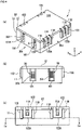
Figure 1 illustrates (a) an isometric view of a connector according to an embodiment of the present invention with a lid removed from a body of a housing and (b) a side view as seen from the direction of an arrow Ib ofFigure 1(a) . -
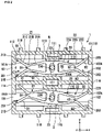
Figure 2 is a cross-sectional view of the connector as taken along line Ia-Ia inFigure 4(c) . -
Figure 3 is the same cross-sectional view asFigure 2 and shows positions, directions, and amounts of displacement. -
Figure 4 illustrates (a) an isometric view of the connector as a whole, (b) a side view as seen from the direction of an arrow IVb ofFigure 4(a), and (c) a side view as seen from the direction of an arrow IVc ofFigure 4(a) . -
Figure 5 illustrates (a) a diagram showing a range of motion of leading ends of beams of a contact and a range of projection of an opening of the housing and (b) a diagram for explaining an example of a process by which a mating partner is inserted into a socket formed by the contact. -
Figure 6 is a top view showing a state in which mating partners are inserted in sockets at both ends of contacts respectively. -
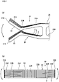
Figure 7 illustrates (a) a top view of a stacked body made from contacts and (b) a side view of the stacked body made from the contacts. - An embodiment of the present invention is described below with reference to the accompanying drawings. As shown in
Figures 1 to 4 , aconnector 1 includes a plurality of plate-like contacts 2 (Figure 2 ) stacked and ahousing 10 retaining thecontacts 2 stacked. Theconnector 1 can be used, for example, in a power carrier circuit that is mounted in a vehicle or other machines. - The
contacts 2 of theconnector 1 of the present embodiment are used for mating with appropriate mating partners 3-1 and 3-2 such as bus bars, circuit boards, and pinshaped or tab-shaped contacts in a stacked state. The mating partners 3-1 and 3-2 are provided in appropriate supporting elements such as a device chassis. Thecontacts 2 formfirst sockets 201 andsecond sockets 202 as a whole in a stacked state. Thefirst sockets 201 receive the first mating partners 3-1. Thesecond sockets 202 receive the second mating partners 3-2. - First, an example of a configuration of the
housing 10 is described. Thehousing 10 includes ahousing body 11 and a lid 12 (Figures 4(a) and 4(b) ) assembled to thehousing body 11. Thehousing body 11 and thelid 12 are each formed by injection molding involving the use of an insulating resin material. Thehousing 10 is formed in the shape of a cuboid as a whole. - The
housing body 11 includes twocavities 110 each of which accommodates astacked body 20 formed by thecontacts 2 being stacked and anengaging pin 111, positioned in each of thecavities 110, that engages with thecontacts 2 of thestacked body 20. Alternatively, thehousing body 11 may include asingle cavity 110 in which a stackedbody 20 is accommodated. Thehousing body 11 is formed in the shape of a box by a rectangularlower wall 112 andside walls 113 to 116 standing from the four sides, respectively, of thelower wall 112. Theside walls lower wall 112. Theside walls lower wall 112. - The interior of the
housing body 11 is divided into the twocavities 110 by a dividingwall 117 positioned parallel to theside walls cavities 110 is given a length, a width, and a height that are needed to accommodate the whole of thestacked body 20. Directions parallel with the length, width, and height of each of thecavities 110 are represented by x, y, and z, respectively. The twocavities 110 are arranged in the y direction. - In each of the
cavities 110, thecontacts 2 are stacked in the z direction. Theengaging pin 111, which stands in the z direction perpendicular to thelower wall 112, passes through thecontacts 2 in a plate thickness direction. - As will be mentioned later, the
contacts 2 are allowed to be displaced with respect to theengaging pin 111. Thehousing body 11 is equivalent to a regulating portion that regulates displacements of thecontacts 2 in a direction of rotation D1 within a certain range by coming into contact with thecontacts 2 and that regulates displacements of thecontacts 2 in a direction of slide D2 by coming into contact with thecontacts 2. Thehousing body 11 of the present embodiment includes theside walls element 118 as a plurality of regulating elements. Theside walls contacts 2. Formed near a central part of each of thecavities 110 in the x direction are a pair of second regulating elements 118 (Figure 3 ) that are parallel to the x direction and that stand in the z direction with respect to thelower wall 12. The regulatingelements 118 are positioned on both sides of thecontacts 2 in the y direction. - The
lid 12 is formed in a rectangular shape, and includes acover portion 121 and a plurality oflock portions 122. Thecover portion 121 covers anopening 119 of thehousing body 11. The plurality oflock portions 122 correspond to a plurality of lockingprojections 11A provided on theside walls housing body 11. Each of theprojections 11A is provided betweenribs 11B that guide a corresponding one of thelock portions 122 in the z direction. When each of thelock portions 122 is warped so that aleading end portion 122A of thelock portion 122 catches a corresponding one of theprojections 11A, thelid 12 is assembled to thehousing body 11. This causes a leading end portion of theengaging pin 111 to engage with the cover portion 121 (seeFigure 4(b) ), which is positioned parallel to thelower wall 112, so that theengaging pin 111 keeps thecontacts 2 stacked. - In the
side walls 114, which is orthogonal to the x direction, twofirst openings 101 corresponding to the respectivefirst sockets 201 of the twostacked bodies 20 are formed in a row in the y direction. Similarly, in theside wall 116, which is orthogonal to the x direction, twosecond openings 102 corresponding to the respectivesecond sockets 202 of the twostacked bodies 20 are formed in a row in the y direction. Thefirst openings 101 are formed with a constant width over the entire height of theside wall 114. The same applies to thesecond openings 102 formed in theside wall 116. - From outside the
housing body 11, the first mating partners 3-1 are inserted into thefirst sockets 201 via thefirst openings 101, and the second mating partners 3-2 are inserted into thesecond sockets 202 via thesecond openings 102. - The
first openings 101 pass though theside wall 114 in the x direction. Thefirst openings 101 haveguide surfaces 101A that guide the first mating partners 3-1 into thecavities 110. The guide surfaces 101A are formed such that the widths of thefirst openings 101 become gradually greater from thecavities 110 toward an outer surface of theside wall 114. Thesecond openings 102, which pass through theside wall 116 in the x direction, also havesimilar guide surfaces 102A. - Next, as shown in
Figures 2 and3 , each of thecontacts 2 includes afirst mating portion 21 that constitutes thefirst socket 201, asecond mating portion 22 that constitutes thesecond socket 202, and a connectingportion 23, positioned at a reference position A of thecontact 2, that connects thefirst mating portion 21 and thesecond mating portion 22 to each other. For example, the reference position A is equivalent to a shaft center of the aforementionedengaging pin 111. In the present embodiment, it is preferable that the reference position A be located in the center of thecavity 110 in a top view of thehousing 10. The connectingportion 23 engages with theengaging pin 111. - The
contact 2 is integrally formed by punching of a plate material composed of a metal material such as an aluminum alloy or a copper alloy. Each of thestacked bodies 20 are formed by stacking identically-shapedcontacts 2 into a state in which flat and smooth surfaces are joined on top of each other. - At the reference position A, a first axis line L1 (
Figure 1(b) ) parallel to the z direction, which is a plate thickness direction (stacking direction) of thecontact 2, is set. Further, at the reference position A, a second axis line L2 dividing a first side to which thefirst socket 201 is directed (first side S1) and a second side to which thesecond socket 202 is directed (second side S2) from each other is set (Figure 3 ). Thefirst mating portion 21 is positioned toward the first side S1 with respect to the reference position A. Thesecond mating portion 22 is positioned toward the second side S2 with respect to the reference position A. - The connecting
portion 23 has formed therein along hole 230 that includes the reference position A and that is long in a direction parallel with the second axis line L2. Thelong hole 230 is located in the center of the connectingportion 23, which is formed in a substantially rectangular shape. Into thelong hole 230, the engagingpin 111, which is circular in cross-section, is inserted. The diameter of theengaging pin 111 is constant over a range within which theengaging pin 111 passes through inside thelong holes 230 of the stackedcontacts 2. Anend portion 230A of thelong hole 230 in the direction parallel with the second axis line L2 is formed in, but is not limited to, an arc shape. Thelong hole 230 may be formed, for example, in a rectangular shape as a whole. - The diameter of the
engaging pin 111 is shorter than the length of the long orlonger hole 230, and the width dimension of thelong hole 230 in a direction orthogonal to the second axis line L2 and the diameter of theengaging pin 111 are equal to each other. There are clearances between portions of an inner peripheral edge of thelong hole 230 that are parallel to the second axis line L2 and an outer peripheral portion of theengaging pin 111. - If the hole of the
contact 2 through which theengaging pin 111 is passed is a circular hole and the connectingportion 23 is tightly positioned between the regulatingelements 118, thecontact 2 and thehousing 10 are integrated in a rigidly-connected state. In that case, thecontact 2 has no degree of freedom of position with respect to mating partners 3-1 and 3-2 that are inserted into thecavity 110 through theopenings housing 10. - In the present embodiment, the engagement of the
engaging pin 111 with thelong hole 230 and the presence of a space in thecavity 110 in which thecontact 2 is allowed to move give the contact 2 a degree of freedom of position. Thecavity 110 includes the respective ranges of motion (ranges of movement) of the connectingportion 23, thefirst mating portion 21, and thesecond mating portion 22. - Based on the degree of freedom of position of the
contact 2, the present embodiment absorbs tolerances of dimensional shape and assembly of thecontact 2, thehousing 10, the mating partners 3-1 and 3-2, or other components through a displacement of thecontact 2. While being retained in thehousing body 11 by the engagingpin 11, thecontact 2 is allowed to undergo a slide displacement in a direction D2 (direction of slide D2) parallel with the second axis line L2 while being guided by the engagingpin 111. In addition, thecontact 2 is also allowed to undergo a rotational displacement in a direction of rotation D1 on the first axis line L1. - The
contact 2 indicated by "N" inFigure 2 is positioned in a design normal position (design position) on an x-y plane. In terms of design, the first mating partner 3-1 is inserted into or removed from thefirst mating portion 21 of thecontact 2, which is positioned in the design position, from a direction parallel with a third axis line L3 orthogonal to the second axis line L2 on the x-y plane. Similarly, in terms of design, the second mating partner 3-2 is inserted into and removed from thesecond mating portion 22 of thecontact 2, which is positioned in the design position, from a direction parallel with a fourth axis line L4. In the present embodiment, assuming that the third axis line L3 is located at 0°, the fourth axis line L4 is located at 180°. - It is preferable that when the
contact 2 is in the design position, the third axis line L3 and the fourth axis line L4 both coincide with the x direction set in thehousing 10. In this case, the second axis line L2 coincides with the y direction. -
Figures 2 and3 show, as an example, a state in which all of thecontacts 2 thestacked bodies 20 are in phase with each other in the direction of rotation D1 (direction of x rotation) and at the same position as each other in the direction of slide D2. Without being bound by this state, each of thecontacts 2 of thestacked bodies 20 can be displaced into any phase in the direction of rotation D1 and any position in the direction of slide D2. In particular, when thecontacts 2 are in a no-load state in which they are not mated with the mating partners 3-1 and 3-2, there are typically variations in the positions of thecontacts 2 in the direction of rotation D1 and the direction of slide D2. - A configuration of each of the
contacts 2 is described in more detail. Thefirst mating portion 21 is equivalent to an elastic body (spring) including a pair of beams B1 that retain a first mating partner 3-1 therebetween. As sections or parts set in the pair of beams B1, thefirst mating portion 21 includes a receivingportion 21A that receives the first mating partner 3-1, acontact portion 21B that is equivalent to a contact point with the first mating partner 3-1, and aguide portion 21C that guides the first mating partner 3-1 toward thecontact portion 21B. - In a section of the receiving
portion 21A joined to the connectingportion 23, the pair ofbeams B 1 extend from both sides of the connectingportion 23 in the direction of slide D2 to thecontact portion 21B with a decreasing dimension between the pair of beams B1. It is preferable that in a no-load state, thecontact portion 21B have set therein a gap G1 into which the first mating partner 3-1 is inserted. The dimension between the pair of beams B1 in theguide portion 21C gradually increases in the direction of slide D2 with respect to the gap G1 away from thecontact portion 21B. - The pair of beams B1 have such an overall shape as to concavely bend toward each other (inward) at the
contact portion 21B. However, thecontact portion 21B is not pointed toward the inside, and the pair of two beams B1 convexly and smoothly curve toward each other at thecontact portion 21B. - The
first mating portion 21 elastically holds and retains the first mating partner 3-1, which is inserted into the receivingportion 21A while spreading out the gap G1 of thefirst contact portion 21B. In order to give thecontact portion 21B rigidity needed to sufficiently retain the first mating partner 3-1, thecontact portion 21B is formed to be thicker in a direction in which the first mating partner 3-1 is held than other parts of the pair of beams B1. As many contact points as the number ofcontacts 2 that are stacked in astacked body 20 are brought about by the first mating partner 3-1 making contact with each of therespective contact portions 21B of thecontacts 2 for conduction. Therefore, the incorporation of theconnector 1 into a power circuit can contribute to an increase in current carrying capacity on the basis of a large number of contact points. - Under conditions where a displacement of the
contact 2 in thecavity 110 is allowed, thecontact portion 21B has ensured therefor a contact load that is greater than a load imposed, for example, by vibrations or impacts during use of a device in which theconnector 1 is incorporated. This prevents thecontact portion 21B of thecontact 2 and the mating partner 3-1 from being displaced during use and keeps them mated with each other. - The
guide portion 21C guides the mating partner 3-1 toward thecontact portion 21B. Since theguide portion 21C spreads toward leadingends 21D of the pair of beams B1, theguide portion 21C can guide the mating partner 3-1 toward the gap G1 of thecontact portion 21B. The greater the distance between the leading ends 21D of the pair of beams B1 in the direction of slide D2 is, the easier it is for the mating partner 3-1 to be captured between the pair of beams B1. Theguide portion 21C of the present embodiment is positioned over a wide range in the direction of slide D2 as the distance d between the pair of beams B1 at the leading ends 21D exceeds the width of the connecting portion 23 (dimension in the direction of slide D2). When thisguide portion 21C comes into contact with theside walls wall 117 due to the displacement of thecontact 2, a further displacement of thecontact 2 is regulated. - As with the
first mating portion 21, thesecond mating portion 22 too is equivalent to a pair of beams B2 that retain a second mating partner 3-2 therebetween. In the present embodiment, thefirst mating portion 21 and thesecond mating portion 22 are formed with point symmetry with respect to the reference position A and formed with line symmetry with respect to the second axis line L2. Therefore, thesecond mating portion 22 includes a receivingportion 22A, acontact portion 22B, and aguide portion 22C that are similar in configuration to the receivingportion 21A, thecontact portion 21B, and theguide portion 21C of thefirst mating portion 21. Thecontact portion 22B too has set therein a gap G2 into which the second mating partner 3-2 is inserted. - The present embodiment makes it possible to, while making it possible to capture the mating partners 3-1 and 3-2 over a wide range in the direction of slide D2 with the
guide portion 21C, which is part of the spring, sufficiently absorb tolerances on the basis of the displaceability of thecontact 2 retained in thehousing 10 and thereby prevent thecontact 2 and the mating partners 3-1 and 3-2 from being subjected to excessive stress. - The
contact 2 may be given an amount of displacement with a limitation needed for tolerance absorption. It is preferable that the amount of displacement of thecontact 2 falls within a certain range sufficient for tolerance absorption so that the leading ends 21D of the pair of beams B1 and the leading ends 22D of the pair of beams B2 do not interfere with the mating partners 3-1 and 3-2 due to a displacement of thecontact 2 by an amount of displacement well over tolerance. - The amount of displacement of the
contact 2 in the direction of slide D2 is restricted to the range of motion of thelong hole 230 in the direction of slide D2 with respect to theengaging pin 111. Alternatively, the amount of displacement of thecontact 2 in the direction of slide D2 is restricted to the range of motion of the connectingportion 23 between the regulatingelements 118 facing each other in the y direction. In the present embodiment, the latter applies, as the range of motion (α1, α2) of the connectingportion 23 is smaller than the range of motion (β1, β2) of thelong hole 230. This is merely an example. In the present embodiment, as in the case of thecontact 2 shown on the upper side on the paper surface ofFigure 6 , the connectingportion 23 comes into contact with the regulatingelements 118 before theengaging pin 111 and theend portion 230A of thelong hole 230 come into contact with each other; therefore, a further displacement of thecontact 2 is regulated. - The amount of displacement of the
contact 2 in the direction of rotation D1 is restricted to the ranges of motion of themating portions wall 117, which function as the first regulating element. For example, if, as indicated by "N" inFigure 2 , thecontact 2 undergoes a rotational displacement from a state in which thecontact 2 is in the design position to a state shown between theside wall 115 and the dividingwall 117 so that thefirst mating portion 21 comes into contact with the dividingwall 117 and thesecond mating portion 22 comes into contact with theside wall 115, thecontact 2 is not further displaced in the direction of rotation D1. At this point in time, the displacement of thecontact 2 in the direction of slide D2 is regulated too. Assuming that thecontact 2 serves as a reference when it is in the design position (N), the amount of rotational displacement of thecontact 2 on theengaging pin 111 is regulated within a certain angular range θ to both sides in the direction of rotation D1 with reference to the design position (N). - Depending on the position of the
contact 2 in the direction of slide D2 with respect to theengaging pin 111, the rotational displacement of thecontact 2 is regulated by only either the first orsecond mating portion contact 2 positioned between the dividingwall 117 and the side wall 115 (e.g. the first mating portion 21) coming into contact with a regulating wall (e.g. the dividing wall 117). At this point in time, thecontact 2 is allowed to be displaced to one side (e.g. the lower side on the paper surface ofFigure 2 ), as the other of the first andsecond mating portions 21 and 22 (e.g. the second mating portion 22) is not in contact with the regulating wall. - When the displacement of the
contact 2 is regulated by thehousing body 11 coming into contact with thedisplaceable contact 2, the site of contact between thehousing body 11 and thecontact 2 and the orientation of displacement of thecontact 2 that is regulated by the contact between thehousing body 11 and thecontact 2 change according to various concrete shapes that thehousing body 11 and thecontact 2 may take. According to the present embodiment, the displacements of thecontact 2 in the direction of rotation D1 and the direction of slide D2 are regulated as the whole of theside walls wall 117, which are capable of coming into contact with theguide portions contact 2, and the regulatingelements 118, which are capable of coming into contact with the connectingportion 23 of thecontact 2. Depending on the respective shapes of thehousing body 11 and thecontact 2, the displacement of thecontact 2 in the direction of rotation D1 may be regulated by contact between the regulatingelements 118 and the connectingportion 23. - It is preferable that as shown, for example, in
Figure 5(a) , the whole (γ1, γ2) of the range ofmotion 2M of the pair of beams B1 at the leading ends 21D in the direction of rotation D1 and the direction of slide D2 with respect to theengaging pin 111 be set outside the range of projection P1 of thefirst opening 101 of thehousing 10 in the x direction by the amount of displacement of thecontact 2 in the direction of rotation D1 and the direction of slide D2 being restricted by theside walls wall 117, and the regulatingelements 118 of thehousing body 11. - Although not illustrated, the range of motion of the pair of beams B2 of the
second mating portion 22 and the range of projection of thesecond opening 102 are symmetrical with their counterparts shown inFigure 5(a) . As described above, it is preferable that the whole range of motion of the pair of beams B2 at the leading ends 22D be set outside the range of projection of thesecond opening 102 projected in the x direction onto thecavity 110. -
Figure 5(a) shows a state in which theleading end 21D of one of the pair of beams B1 of thefirst mating portion 21 has been maximally displaced to the upper side of the paper surface to the position of theside wall 113. At this point in time, theleading end 21D of the other of the pair of beams B1 is located outside the range of projection P1 while in closest proximity to thefirst opening 101. Therefore, there is no obstacle to receiving the first mating partner 3-1 between the pair of beams B1 through thefirst opening 101 and mating the first mating partner 3-1 with thefirst mating portion 21. - For example, as shown in
Figure 5(b) , the first mating partner 3-1 is inserted into thefirst opening 101 without being interfered with by the pair of beams B1. Moreover, the first mating partner 3-1 reaches the receivingportion 21A by spreading out the gap G1 while pushing theguide portion 21C to displace theguide portion 21C downward on the paper surface by at least either a rotational displacement or slide displacement of thecontact 2. By thus allowing thecontact 2 to be displaced in the process of insertion, the mating partner 3-1 can be inserted into themating portion 21 with reduced stress on thecontact 2 and the mating partner 3-1. The mating partner 3-1 may be inserted into themating portion 21 from any of various directions, as the first mating partner 3-1 may assume any of various positions with respect to thecontact 2. Thecontact portion 21B is given a smoothly curved shape so that the mating partner 3-1 can be received into the gap G1 from any of the various directions and thecontact portion 21B and the mating partner 3-1 can be appropriately brought into contact with each other. The same applies to thecontact portion 22B of thesecond mating portion 22. - According to the present embodiment, the engagement of the
engaging pin 111 with thelong hole 230 makes it possible to cause thecontact 2 to be displaced in the direction of rotation D1 and the direction of slide D2 by following the mating partners 3-1 and 3-2. This makes it possible to, as shown, for example, inFigure 6 , mate the mating partners 3-1 and 3-2 with thesocket 201 formed by thefirst mating portion 21 and thesocket 202 formed by thesecond mating portion 22, respectively, while absorbing assembly tolerances of dimensional shape and assembly of elements and preventing thecontact 2 and the mating partners 3-1 and 3-2 from being subjected to excessive stress. - The mating partners 3 are not necessarily positioned parallel to the x direction, and may be inclined with respect to the x direction as indicated by chain double-dashed lines. Even in such a case, the mating partners 3-1 and 3-2 can be smoothly inserted into the
first mating portion 21 and thesecond mating portion 22, respectively, by thecontact 2 being displaceable in a synthetic or resultant direction corresponding to a combination of the direction of rotation D1 and the direction of slide D2. - If the
contact 2 is not displaced from the design position, a mating partner 3-1 captured between the pair of beams B1 and guided toward thecontact portion 21B by theguide portion 21C cannot be smoothly received into thecontact portion 21B or the receivingportion 21A, so that excessive stress may be applied. If thecontact 2 is displaceable but is displaced only in the direction of rotation D1, a mating partner 3-1 positioned particularly along the x direction cannot be smoothly received, so that excessive stress may be applied. - According to the present embodiment, even in the case of mating partners 3-1 and 3-2 shifted in the y direction as in the case of mating partners 3-1 and 3-2 mated with the
contact 2 shown on the lower side on the paper surface ofFigure 6 , a rotational displacement and a slide displacement of thecontact 2 makes it possible to stably connect the mating partners 3-1 and 3-2 to thefirst mating portion 21 and thesecond mating portion 22, respectively, while preventing thecontact 2 and the mating partners 3-1 and 3-2 from being subjected to excessive stress. - The
contacts 2 of astacked body 20 can be displaced to spread like a fan in the direction of rotation D1 as shown, for example, inFigure 7(a) and, although not illustrated, can be displaced to spread in the direction of slide D2, and tolerances can be absorbed by such displacement behavior. For example, thought is given to a case where a mating partner 3-1 inclined with respect to the stacking direction (z direction) is inserted into thesocket 201. In that case, the mating partner 3-1 can be inserted into thesocket 201 by displacing thefirst mating portion 21 of eachcontact 2 as shown, for example, inFigure 7(a) in conformance with the mating partner 3-1. - Furthermore, as shown in (b) of
Figure 7 , therespective mating portions stacked contacts 2 are displaced by warpage so that the leading ends 21D and 22D open in a direction along the stacking direction (z direction), whereby tolerances can be absorbed by causing thecontacts 2 to follow the mating partners 3-1 and 3-2 as the whole of the stackedbody 20. Themating portions - Other than those above, the components named in the foregoing embodiment can be accepted or rejected or may be appropriately replaced by other components without departing from the scope of the present invention.
Contacts 2 accommodated in thehousing 10 do not need to be stacked. Even in a case where only asingle contact 2 is accommodated in thehousing 10, working effects substantially the same as those of the foregoing embodiment can be brought about. In a case where only asingle contact 2 is accommodated in thehousing 10, thecontact 2 may be given a degree of freedom in a direction along the second axis line L2 by forming, in thehousing 10, a long hole that extends parallel to the second axis line L2 when thecontact 2 is positioned in a state indicated by "N", for example, inFigure 3 and providing thecontact 2 with a projecting engaging portion that is inserted into the long hole. - In the foregoing embodiment,
contacts 2 are stacked, and onestacked body 20 forms one position as a whole. This is not intended to impose any limitation, butcontacts 2 may be applied to a multiposition connector. In that case, asingle contact 2 or a plurality ofcontacts 2 stacked are accommodated in each of a plurality of cavities of a connector housing. In the case of such a multiposition configuration, engaging pins formed separately in each of the connectingportions 23 of a plurality ofcontacts 2 may be passed through long holes of a connector housing, or as in the case of the foregoing embodiment, an engagingpin 111 common to a plurality ofcontacts 2 may be passed through along hole 230 of the connectingportion 23 of eachcontact 2. - The
first mating portion 21 and thesecond mating portion 22 do not necessarily need to be positioned with 180-degree inverted orientation from each other. A case is allowed where a third axis line L3 set in thefirst mating portion 21 and a fourth axis line L4 set in thesecond mating portion 22 form an angle of, for example, 160-degree. Further, thecontact 2 may include a third mating portion in addition to thefirst mating portion 21 and thesecond mating portion 22. - A
single contact 2 or stackedcontacts 2 are not only necessarily incorporated into thehousing 10 for use but also may be assembled to an appropriate supporting medium for use. The supporting medium may be thehousing body 11 shown inFigure 1 . Alternatively, the supporting medium may be one that includes only anengaging pin 111 and nearby components. Such a supporting medium includes, for example, an engagingpin 111, is assembled to the connectingportions 23 ofcontacts 2 stacked, and keeps thecontacts 2 stacked. The supporting medium and astacked body 20 made fromcontacts 2 can be provided as a contact assembly. In a case where the supporting medium does not include ahousing body 11, the corresponding mating partners 3-1 and 3-2 can be directly inserted into thefirst mating portion 21 and thesecond mating portion 22 without passing through theopenings -
- 1...
- Connector
- 2...
- Contact
- 2M...
- Range of motion (range of movement)
- 3-1...
- First mating partner (mating partner)
- 3-2...
- Second mating partner (mating partner)
- 10...
- Housing
- 11...
- Housing body (regulating portion)
- 11...
- Projection
- 11B...
- Rib
- 12...
- Lid
- 20...
- Stacked body
- 21...
- First mating portion
- 21A...
- Receiving portion
- 21B...
- Contact portion (first contact portion)
- 21C...
- Guide portion (first guide portion)
- 21D...
- Leading end
- 22...
- Second mating portion
- 22A...
- Receiving portion
- 22B...
- Contact portion (second contact portion)
- 22C...
- Guide portion (second guide portion)
- 22D...
- Leading end
- 23...
- Connecting portion
- 101...
- First opening
- 101A...
- Guide surface
- 102...
- Second opening
- 102A...
- Guide surface
- 110...
- Cavity
- 111...
- Engaging pin (engaging portion)
- 112...
- Lower wall
- 113, 115...
- Side wall
- 114, 116...
- Side wall
- 117...
- Dividing wall
- 118...
- Regulating element
- 119...
- Opening
- 121...
- Cover portion
- 122...
- Lock portion
- 122A...
- Leading end portion
- 201...
- First socket
- 202...
- Second socket
- 230...
- Long hole
- 230A...
- End portion
- A...
- Reference position
- B1...
- Pair of beams (first pair of beams)
- B2...
- Pair of beams (second pair of beams)
- d...
- Distance
- D1...
- Direction of rotation (direction of rotation on first axis line)
- D2...
- Direction of slide (direction parallel with second axis line)
- G1...
- Gap (first gap)
- G2...Gap
- (second gap)
- L1...
- First axis line
- L2...
- Second axis line
- L3...
- Third axis line
- L4...
- Fourth axis line
- P1...
- First range of projection
- S1...
- First side (first side with respect to reference position)
- S2...
- First side (second side with respect to reference position)
- θ...
- Angular range
Claims (10)
- A contact (2) shaped like a plate forming a first socket (201) and a second socket (202) for use in mating, the contact (2) comprising:a first mating portion (21) that constitutes the first socket (201) and that is positioned toward a first side (S1) with respect to a reference position (A);a second mating portion (22) that constitutes the second socket (202) and that is positioned toward a second side (S2) with respect to the reference position (A); anda connecting portion (23), positioned at the reference position (A), that connects the first mating portion (21) and the second mating portion (22) to each other,the contact (2) being allowed to be displaced with respect to an engaging portion (111) in both a direction of rotation (D1) on a first axis line (L1) set along a plate thickness direction of the contact (2) at the reference position (A) and a direction parallel with a second axis line (L2) dividing the first side (S1) and the second side (S2) from each other at the reference position (A), the engaging portion (111) engaging with the connecting portion (23).
- The contact (2) according to claim 1, wherein the connecting portion (23) has formed therein an elongate hole (230) in which the reference position (A) is situated and that is longer in the direction parallel with the second axis line (L2) than in a direction perpendicular thereto.
- The contact according to claim 1 or 2, whereinthe first mating portion (21) is an elastic body including a first pair of beams (B1) that retain a first mating partner (3-1) therebetween and includes a first contact portion (21B) that makes contact with the first mating partner (3-1) and a first guide portion (21C) that guides the first mating partner (3-1) toward the first contact portion (21B),the second mating portion (22) is an elastic body including a second pair of beams (B2) that retain a second mating partner (3-2) therebetween and includes a second contact portion (22B) that makes contact with the second mating partner (3-2) and a second guide portion (22C) that guides the second mating partner (3-2) toward the second contact portion (22B),a dimension (d) of the first guide portion (21C) between the first pair of beams (B1) increases in the direction parallel with the second axis line (L2) away from the first contact portion (21B), anda dimension of the second guide portion (22C) between the second pair of beams (B2) increases in the direction parallel with the second axis line (L2) away from the second contact portion (22B).
- The contact (2) according to claim 3, whereinthe first pair of beams (B1) smoothly curve convexly toward each other at the first contact portion (21B), andthe second pair of beams (B2) smoothly curve convexly toward each other at the second contact portion (22B).
- A connector (1) comprising:the contact according to any one of claims 1 to 4, the contact (2) comprising a single contact or a plurality of contacts forming the first socket (201) and the second socket (202) in a stacked state; anda housing (10) retaining the contact (1),the housing (10) includinga cavity (110) that accommodates the contact (1), andthe engaging portion (111) that engages with the connecting portion (23) of the contact (1).
- The connector (1) according to claim 5, whereinthe connecting portion (23) has formed therein an elongate hole (230) in which the reference position (A) is situated and that is longer in the direction parallel with the second axis line (L2) than in a direction perpendicular thereto, andthe engaging portion (111) is equivalent to a pin that is inserted into the elongate hole (230).
- The connector (1) according to claim 5 or 6, wherein the housing (10) includes a first opening (101) through which a first mating partner (3-1) corresponding to the first mating portion (21) is inserted and a second opening (102) through which a second mating partner (3-2) corresponding to the second mating portion (22) is inserted.
- The connector (1) according to any one of claims 5 to 7, wherein the housing (10) includes a regulating portion (11) that regulates a displacement of the contact (2) in the direction of rotation (D1) on the first axis line (L1) within a certain range by coming into contact with the contact (2) and that regulates a displacement of the contact (2) in a direction (D2) parallel with the second axis line (L2) by coming into contact with the contact (2).
- The connector (1) according to claim 8, whereinthe housing (10) includes a first opening (101) through which a first mating partner (3-1) corresponding to the first mating portion (21) is inserted and a second opening (102) through which a second mating partner (3-2) corresponding to the second mating portion (22) is inserted,in a first contact portion (21B) equivalent to a contact point of the first mating portion (21), a first gap (G1) into which the first mating partner (3-1) is inserted is set or present,in a second contact portion (22) equivalent to a contact point of the second mating portion (22), a second gap (G2) into which the second mating partner (3-2) is inserted is set or present,regulating the displacement of the contact (2) through the regulating portion (11) causes a range of motion of a leading end (21D) of the first mating portion (21) to be set outside a range of projection of the first opening (101) and causes a range of motion (2M) of a leading end (22D) of the second mating portion (22) to be set outside a range of projection (P1) of the second opening (102).
- A contact assembly comprising:the contact (2) according to any one of claims 1 to 4, the contact (2) comprising a plurality of contacts forming the first socket (201) and the second socket (202) in a stacked state; anda support medium that includes the engaging portion (111) and, by being assembled to the connecting portions (23) of the plurality of contacts (2), maintains the contacts (2) in a stacked state.
Applications Claiming Priority (1)
| Application Number | Priority Date | Filing Date | Title |
|---|---|---|---|
| JP2021059565A JP7695005B2 (en) | 2021-03-31 | 2021-03-31 | Contact laminate, connector and contact assembly |
Publications (1)
| Publication Number | Publication Date |
|---|---|
| EP4068529A1 true EP4068529A1 (en) | 2022-10-05 |
Family
ID=80979160
Family Applications (1)
| Application Number | Title | Priority Date | Filing Date |
|---|---|---|---|
| EP22164846.2A Withdrawn EP4068529A1 (en) | 2021-03-31 | 2022-03-28 | Floating contact, connector and contact assembly |
Country Status (4)
| Country | Link |
|---|---|
| US (1) | US20220320778A1 (en) |
| EP (1) | EP4068529A1 (en) |
| JP (1) | JP7695005B2 (en) |
| CN (1) | CN115149294A (en) |
Families Citing this family (1)
| Publication number | Priority date | Publication date | Assignee | Title |
|---|---|---|---|---|
| CN116683220A (en) * | 2023-06-02 | 2023-09-01 | 东莞立讯技术有限公司 | Electric connector |
Citations (5)
| Publication number | Priority date | Publication date | Assignee | Title |
|---|---|---|---|---|
| US4423917A (en) * | 1981-11-19 | 1984-01-03 | Amp Incorporated | Electrical connector having movable contact units |
| JPS62158778U (en) * | 1986-03-28 | 1987-10-08 | ||
| JPH0411346B2 (en) | 1984-04-13 | 1992-02-28 | ||
| US20120156909A1 (en) * | 2010-12-17 | 2012-06-21 | Tyco Electronics Corporation | Power connector assembly |
| JP2019523537A (en) | 2016-08-01 | 2019-08-22 | ティーイー・コネクティビティ・コーポレイションTE Connectivity Corporation | Power connector system |
Family Cites Families (8)
| Publication number | Priority date | Publication date | Assignee | Title |
|---|---|---|---|---|
| JPH07111888B2 (en) * | 1993-07-12 | 1995-11-29 | 不二電機工業株式会社 | Power clip |
| JP4317831B2 (en) * | 2005-03-31 | 2009-08-19 | 日本圧着端子製造株式会社 | Deviation absorbing printed wiring board connector |
| JP2011060732A (en) * | 2009-09-14 | 2011-03-24 | Japan Aviation Electronics Industry Ltd | Connector |
| JP5631080B2 (en) * | 2010-07-02 | 2014-11-26 | 日本航空電子工業株式会社 | connector |
| US10763607B2 (en) * | 2016-08-22 | 2020-09-01 | Interplex Industries, Inc. | Electrical connector |
| CN111373608B (en) * | 2017-11-20 | 2022-05-24 | 怡得乐工业有限公司 | Electrical connector |
| JP7086620B2 (en) * | 2018-01-31 | 2022-06-20 | ヒロセ電機株式会社 | Connector and connector system |
| DE102021111935B3 (en) * | 2021-05-07 | 2022-04-21 | Lumberg Connect Gmbh | plug contact |
-
2021
- 2021-03-31 JP JP2021059565A patent/JP7695005B2/en active Active
-
2022
- 2022-03-22 US US17/701,248 patent/US20220320778A1/en not_active Abandoned
- 2022-03-28 CN CN202210310057.6A patent/CN115149294A/en active Pending
- 2022-03-28 EP EP22164846.2A patent/EP4068529A1/en not_active Withdrawn
Patent Citations (5)
| Publication number | Priority date | Publication date | Assignee | Title |
|---|---|---|---|---|
| US4423917A (en) * | 1981-11-19 | 1984-01-03 | Amp Incorporated | Electrical connector having movable contact units |
| JPH0411346B2 (en) | 1984-04-13 | 1992-02-28 | ||
| JPS62158778U (en) * | 1986-03-28 | 1987-10-08 | ||
| US20120156909A1 (en) * | 2010-12-17 | 2012-06-21 | Tyco Electronics Corporation | Power connector assembly |
| JP2019523537A (en) | 2016-08-01 | 2019-08-22 | ティーイー・コネクティビティ・コーポレイションTE Connectivity Corporation | Power connector system |
Also Published As
| Publication number | Publication date |
|---|---|
| CN115149294A (en) | 2022-10-04 |
| JP2022156061A (en) | 2022-10-14 |
| US20220320778A1 (en) | 2022-10-06 |
| JP7695005B2 (en) | 2025-06-18 |
Similar Documents
| Publication | Publication Date | Title |
|---|---|---|
| JP6456572B2 (en) | Automotive electronics | |
| WO2017115693A1 (en) | Floating connector device | |
| EP2822102B1 (en) | Electrical connector | |
| EP3646412B1 (en) | Electrical connector with terminal alignment plate and secondary lock detection, and method of mating | |
| JP2003197310A (en) | Electrical connector | |
| EP4068529A1 (en) | Floating contact, connector and contact assembly | |
| KR20180046886A (en) | Board connector | |
| KR101315664B1 (en) | Fuse unit | |
| CN117335192A (en) | Connector assembly | |
| US7108536B2 (en) | Socket connector having structure for preventing sideways movement | |
| CN111755885B (en) | Connector device and connector | |
| EP2874175B1 (en) | Fuse holder and fuse cover with fixing structure | |
| JPWO2017082228A1 (en) | Connector device | |
| JP6876460B2 (en) | Protector | |
| JP6084107B2 (en) | connector | |
| CN110233370A (en) | Terminal, connector and electrical connector | |
| JP7098678B2 (en) | Protector and wire harness | |
| US12230952B2 (en) | Electrical cable fixing jig and vehicle | |
| JP7845454B2 (en) | Locking mechanism, power supply | |
| US12106917B2 (en) | Socket | |
| CN120879155A (en) | Bus bar holder and method for manufacturing bus bar holder | |
| JP2024163541A (en) | Housings and Card Edge Connectors | |
| JP2024175232A (en) | Electronic Control Unit | |
| JP2024163540A (en) | Housings and Card Edge Connectors | |
| JP2023018975A (en) | nut box |
Legal Events
| Date | Code | Title | Description |
|---|---|---|---|
| PUAI | Public reference made under article 153(3) epc to a published international application that has entered the european phase |
Free format text: ORIGINAL CODE: 0009012 |
|
| STAA | Information on the status of an ep patent application or granted ep patent |
Free format text: STATUS: THE APPLICATION HAS BEEN PUBLISHED |
|
| AK | Designated contracting states |
Kind code of ref document: A1 Designated state(s): AL AT BE BG CH CY CZ DE DK EE ES FI FR GB GR HR HU IE IS IT LI LT LU LV MC MK MT NL NO PL PT RO RS SE SI SK SM TR |
|
| STAA | Information on the status of an ep patent application or granted ep patent |
Free format text: STATUS: THE APPLICATION IS DEEMED TO BE WITHDRAWN |
|
| 18D | Application deemed to be withdrawn |
Effective date: 20230406 |