EP4068522A1 - Structure for connecting aluminum cable and terminal, and vehicle having same - Google Patents
Structure for connecting aluminum cable and terminal, and vehicle having same Download PDFInfo
- Publication number
- EP4068522A1 EP4068522A1 EP20892663.4A EP20892663A EP4068522A1 EP 4068522 A1 EP4068522 A1 EP 4068522A1 EP 20892663 A EP20892663 A EP 20892663A EP 4068522 A1 EP4068522 A1 EP 4068522A1
- Authority
- EP
- European Patent Office
- Prior art keywords
- cable
- terminal
- welding portion
- welding
- aluminum
- Prior art date
- Legal status (The legal status is an assumption and is not a legal conclusion. Google has not performed a legal analysis and makes no representation as to the accuracy of the status listed.)
- Granted
Links
Images

Classifications
-
- H—ELECTRICITY
- H01—ELECTRIC ELEMENTS
- H01R—ELECTRICALLY-CONDUCTIVE CONNECTIONS; STRUCTURAL ASSOCIATIONS OF A PLURALITY OF MUTUALLY-INSULATED ELECTRICAL CONNECTING ELEMENTS; COUPLING DEVICES; CURRENT COLLECTORS
- H01R4/00—Electrically-conductive connections between two or more conductive members in direct contact, i.e. touching one another; Means for effecting or maintaining such contact; Electrically-conductive connections having two or more spaced connecting locations for conductors and using contact members penetrating insulation
- H01R4/02—Soldered or welded connections
- H01R4/029—Welded connections
-
- H—ELECTRICITY
- H01—ELECTRIC ELEMENTS
- H01R—ELECTRICALLY-CONDUCTIVE CONNECTIONS; STRUCTURAL ASSOCIATIONS OF A PLURALITY OF MUTUALLY-INSULATED ELECTRICAL CONNECTING ELEMENTS; COUPLING DEVICES; CURRENT COLLECTORS
- H01R4/00—Electrically-conductive connections between two or more conductive members in direct contact, i.e. touching one another; Means for effecting or maintaining such contact; Electrically-conductive connections having two or more spaced connecting locations for conductors and using contact members penetrating insulation
- H01R4/02—Soldered or welded connections
- H01R4/023—Soldered or welded connections between cables or wires and terminals
-
- H—ELECTRICITY
- H01—ELECTRIC ELEMENTS
- H01R—ELECTRICALLY-CONDUCTIVE CONNECTIONS; STRUCTURAL ASSOCIATIONS OF A PLURALITY OF MUTUALLY-INSULATED ELECTRICAL CONNECTING ELEMENTS; COUPLING DEVICES; CURRENT COLLECTORS
- H01R4/00—Electrically-conductive connections between two or more conductive members in direct contact, i.e. touching one another; Means for effecting or maintaining such contact; Electrically-conductive connections having two or more spaced connecting locations for conductors and using contact members penetrating insulation
- H01R4/58—Electrically-conductive connections between two or more conductive members in direct contact, i.e. touching one another; Means for effecting or maintaining such contact; Electrically-conductive connections having two or more spaced connecting locations for conductors and using contact members penetrating insulation characterised by the form or material of the contacting members
- H01R4/62—Connections between conductors of different materials; Connections between or with aluminium or steel-core aluminium conductors
- H01R4/625—Soldered or welded connections
-
- H—ELECTRICITY
- H01—ELECTRIC ELEMENTS
- H01R—ELECTRICALLY-CONDUCTIVE CONNECTIONS; STRUCTURAL ASSOCIATIONS OF A PLURALITY OF MUTUALLY-INSULATED ELECTRICAL CONNECTING ELEMENTS; COUPLING DEVICES; CURRENT COLLECTORS
- H01R11/00—Individual connecting elements providing two or more spaced connecting locations for conductive members which are, or may be, thereby interconnected, e.g. end pieces for wires or cables supported by the wire or cable and having means for facilitating electrical connection to some other wire, terminal, or conductive member, blocks of binding posts
- H01R11/11—End pieces or tapping pieces for wires, supported by the wire and for facilitating electrical connection to some other wire, terminal or conductive member
- H01R11/12—End pieces terminating in an eye, hook, or fork
-
- H—ELECTRICITY
- H01—ELECTRIC ELEMENTS
- H01R—ELECTRICALLY-CONDUCTIVE CONNECTIONS; STRUCTURAL ASSOCIATIONS OF A PLURALITY OF MUTUALLY-INSULATED ELECTRICAL CONNECTING ELEMENTS; COUPLING DEVICES; CURRENT COLLECTORS
- H01R43/00—Apparatus or processes specially adapted for manufacturing, assembling, maintaining, or repairing of line connectors or current collectors or for joining electric conductors
- H01R43/02—Apparatus or processes specially adapted for manufacturing, assembling, maintaining, or repairing of line connectors or current collectors or for joining electric conductors for soldered or welded connections
- H01R43/0207—Ultrasonic-, H.F.-, cold- or impact welding
Definitions
- This application relates to the field of high-voltage connection technologies, and in particular, to a connection structure of an aluminum cable and a terminal and a vehicle including the connection structure of an aluminum cable and a terminal.
- An aluminum material has defects such as a low strength, poor creep resistance, and a surface easily oxidizable in air. Therefore, when a high-voltage wiring harness is connected with a copper terminal through an aluminum cable by ultrasonic welding instead of cold pressing crimping.
- an objective of this application is to provide a connection structure of an aluminum cable and a terminal, and the connection structure of an aluminum cable and a terminal can balance the electric conduction performance, overcurrent capability, and mechanical strength.
- This application further provides a vehicle including the connection structure of an aluminum cable and a terminal.
- connection structure of an aluminum cable and a terminal includes: an aluminum cable, including a cable core, where the cable core is constructed with a cable welding portion; and a terminal, welded to the cable welding portion, where a nominal cross-sectional area of the cable core is M, and a welding area S between the cable welding portion and the terminal meets 5 ⁇ M ⁇ S ⁇ 6 ⁇ M.
- connection structure of an aluminum cable and a terminal of this embodiment of this application can balance the electric conduction performance, overcurrent capability, and mechanical strength.
- a width of the cable welding portion corresponding to the nominal cross-sectional area M is W
- a length L of the cable welding portion meets 5 ⁇ M/W ⁇ L ⁇ 6 ⁇ M/W.
- a surface of the cable welding portion facing away from the terminal is constructed as a wave surface, and a peak and a valley of the wave surface are distributed in a length direction of the cable welding portion.
- a minimum thickness H of the cable welding portion is a distance between a surface of the cable welding portion facing the terminal and the valley, a width of the cable welding portion corresponding to the nominal cross-sectional area M is W, and the minimum thickness H meets 0.7 ⁇ M/W ⁇ H ⁇ 0.8 ⁇ M/W.
- a maximum angle between the peak and the surface of the cable welding portion facing the terminal ranges from 30° to 60°; and a maximum angle ⁇ between the valley and the surface of the cable welding portion facing the terminal ranges from 30° to 60°.
- the aluminum cable further includes an insulating sleeve, sleeved on an outer side of the cable core, where the cable welding portion extends out of the insulating sleeve; and the terminal includes a terminal welding portion and a crimping portion, the cable welding portion is welded to the terminal welding portion, and the crimping portion is crimped to the insulating sleeve.
- a thickness of the crimping portion is less than a thickness of the terminal welding portion.
- the crimping portion includes a connecting portion and two crimping wings, one end of the connecting portion is connected with the terminal welding portion, the other end of the connecting portion is connected with the two crimping wings, and the two crimping wings clamp the insulating sleeve and are staggered in a length direction of the insulating sleeve.
- the length of the cable welding portion is L, and a length L1 of the connecting portion meets 0.7L ⁇ L1 ⁇ 0.9L.
- a vehicle includes the connection structure of an aluminum cable and a terminal according to the embodiment of the first aspect of this application.
- orientation or position relationships indicated by the terms such as “length”, “width”, “thickness”, “inside”, and “outside” are based on orientation or position relationships shown in the accompanying drawings, and are used only for ease and brevity of illustration and description of this application, rather than indicating or implying that the mentioned apparatus or element needs to have a particular orientation or needs to be constructed and operated in a particular orientation. Therefore, such terms should not be construed as a limitation on this application.
- connection structure of an aluminum cable and a terminal includes an aluminum cable 10 and a terminal 20.
- the aluminum cable 10 includes a cable core 11, the cable core 11 is made of an aluminum material, and the cable core 11 is constructed with a cable welding portion 12.
- the terminal 20 may be a copper terminal, and for example, the terminal 20 is welded to the cable welding portion 12 in an ultrasonic welding manner.
- a nominal cross-sectional area of the cable core 11 is M, and a welding area S between the cable welding portion 12 and the terminal 20 meets 5 ⁇ M ⁇ S ⁇ 6 ⁇ M. It may be understood that, the nominal cross-sectional area M of the cable core 11 may be understood as a cross-sectional area of the cable core 11.
- an ultrasonic welding processing process mainly includes three steps: positioning, cable placing, and welding.
- the terminal 20 is first placed on a positioning block of an ultrasonic welding device, two welding fixtures 1 on the left and right sides are movably pressed on the terminal 20, and a size between the two welding fixtures 1 on the left and right sides is limited to be a size of a welding head 2.
- the cable core of the aluminum cable 10 is placed in the two welding fixtures 1, and the welding head 2 moves downward vertically, to weld the exposed cable core 11 of the aluminum cable 10 and the terminal 20.
- the cable core 11 is generally circular in shape, the part welded by the welding head 2 is pressed into a flat shape, namely, the cable welding portion 12, and the nominal cross-sectional area M of the cable core 11 in the embodiments of this application refers to a cross-sectional area of the circular part.
- connection structure of an aluminum cable and a terminal in the embodiments of this application, because the mass of the aluminum cable 10 is 2/3 of the mass of a copper cable, and the cost of the aluminum cable 10 is 2/3 of the cost of the copper cable, objectives of cost reduction and light weight are achieved by using the connection structure of an aluminum cable and a terminal. Further, setting the welding area between the aluminum cable 10 and the terminal 20 to be 5 ⁇ M ⁇ S ⁇ 6 ⁇ M can prevent the welding area from being excessively small or excessively large. To be specific, on one hand, if the welding area is excessively small, a high temperature is generated due to excessively concentrated welding energy, leading to overwelding and an insufficient mechanical strength after welding, finally reducing the use reliability of the aluminum cable 10.
- the welding area is excessively small, a current allowed to pass through per square millimeter of the welding area is excessively large, a welding part may be easily burnt out, leading to a short service life of the welding part.
- a current allowed to pass through per square millimeter of the welding area is excessively small, and the electric conduction performance of the aluminum cable is further reduced. Therefore, by setting the welding area to be 5 ⁇ M ⁇ S ⁇ 6 ⁇ M in this application, aluminum cables in different specifications can balance the electric conduction performance, overcurrent capability, and mechanical strength.
- a width of the cable welding portion 12 corresponding to the nominal cross-sectional area M is W
- a length L of the cable welding portion 12 meets 5 ⁇ M/W ⁇ L ⁇ 6 ⁇ M/W.
- the widths of the cable welding portions 12 thereof are fixed accordingly.
- the length L of the cable welding portion 12 may be set to be 5 ⁇ M/W ⁇ L ⁇ 6 ⁇ M/W, to ensure to achieve good electric conduction performance, overcurrent capability, and mechanical strength after the cable welding portion is welded to the terminal 20.
- setting the length L of the cable welding portion 12 to be 5 ⁇ M/W ⁇ L ⁇ 6 ⁇ M/W can prevent the length from being excessively short or excessively long.
- the welding area is excessively small, a high temperature is generated due to excessively concentrated welding energy, leading to overwelding and an insufficient mechanical strength after welding, finally reducing the use reliability of the aluminum cable 10.
- the length L of the cable welding portion 12 is excessively long, the length of the terminal 20 is increased, the structure of a connector to which the connection structure of an aluminum cable and a terminal is applied is re-designed, which increases design costs, as well as material costs of the terminal.
- the nominal cross-sectional area M of the cable core 11 is 50 mm 2
- the width W of the corresponding cable welding portion 12 is 16 mm
- the length L of the cable welding portion 12 meets 15.6 mm ⁇ L ⁇ 18.8 mm.
- the nominal cross-sectional area M of the cable core 11 is 70 mm 2
- the width W of the corresponding cable welding portion 12 is 21 mm
- the length L of the cable welding portion 12 meets 16.7 mm ⁇ L ⁇ 20 mm.
- a surface of the cable welding portion 12 facing away from the terminal 20 is constructed as a wave surface 14, and a peak and a valley of the wave surface 14 are distributed in a length direction of the cable welding portion 12.
- a minimum thickness H of the cable welding portion 12 is a distance between a surface of the cable welding portion 12 facing the terminal 20 and the valley, a width of the cable welding portion 12 corresponding to the nominal cross-sectional area M is W, and the minimum thickness H of the cable welding portion 12 meets 0.7 ⁇ M/W ⁇ H ⁇ 0.8 ⁇ M/W.
- the minimum thickness H of the cable welding portion 12 meets a compression ratio of 70% to 80%.
- the minimum thickness H is less than the compression ratio of 70%, cable breaking of welding may easily occur, leading to a decrease in the electrical conductivity of the aluminum cable 10; and when the minimum thickness H is higher than the compression ratio of 80%, a risk that the welding mechanical tension strength does not reach the standard may easily occur. Further, good welding appearance can be achieved when the minimum thickness H of the cable welding portion 12 meets the compression ratio of 70% to 80%.
- the nominal cross-sectional area M of the cable core 11 is 50 mm 2
- the width W of the corresponding cable welding portion 12 is 16 mm
- the minimum thickness H of the cable welding portion 12 meets 2.2 mm ⁇ H ⁇ 2.5 mm. Therefore, the welding compression ratio of the aluminum cable 10 meets 70% to 80%.
- the wave surface 14 adopts a welding texture with large and few waves.
- the quantities of the peaks and the valleys of the wave surface 14 are both 2, namely, two peaks and two valleys are uniformly distributed on the wave surface 14 of the cable welding portion 12.
- a maximum angle between the peak and the surface of the cable welding portion 12 facing the terminal 20 ranges from 30° to 60°. That is, an acute angle between a tangent line of a part of the peak closest to the valley and a welding surface of the cable welding portion 12 ranges from 30° to 60°.
- a maximum angle ⁇ between the valley and the surface of the cable welding portion 12 facing the terminal 20 ranges from 30° to 60°. That is, an acute angle between a tangent line of a part of the valley closest to the peak and a welding surface of the cable welding portion 12 ranges from 30° to 60°.
- a tensile strength of a cable core of a high-voltage aluminum cable used by new energy vehicles is generally from 70 MPa to 120 MPa, so that smooth transition of the welding surface of the aluminum cable 10 can be ensured by adjusting the angles of the peak and the valley, without causing damage to a surface of the cable core 11. Therefore, a larger effective welding area is provided between the cable welding portion 12 and the terminal 20.
- the aluminum cable 10 further includes an insulating sleeve 13.
- the insulating sleeve 13 is sleeved on an outer side of the cable core 11, and the cable welding portion 12 extends out of the insulating sleeve 13.
- the terminal 20 includes a terminal welding portion 21 and a crimping portion 22, the cable welding portion 12 is welded to the terminal welding portion 21, and the crimping portion 22 is crimped to the insulating sleeve 13.
- the crimping portion 22 includes a connecting portion 24 and two crimping wings 23.
- One end of the connecting portion 24 is connected with the terminal welding portion 21, and the other end of the connecting portion 24 is connected with the two crimping wings 23.
- the two crimping wings 23 clamp the insulating sleeve 13, and the two crimping wings 23 are staggered in a length direction of the insulating sleeve 13.
- the crimping portion 22 includes the two staggered crimping wings 23, the insulating sleeve 13 of the aluminum cable 10 is arranged running through a channel formed by the two crimping wings 23, and the two crimping wings 23 are crimped to an outer surface of the insulating sleeve 13 of the aluminum cable 10 by using a crimping fixture. Therefore, the crimping wings 23 are fixedly connected to the insulating sleeve 13 of the aluminum cable 10, and the crimping wings 23 can transfer mechanical stress acting on a welding region to the insulating sleeve 13 of the aluminum cable 10, thereby effectively avoiding damage to the welding part caused by pulling the aluminum cable 10.
- a thickness of the crimping portion 22 is less than a thickness of the terminal welding portion 21, and in a radial direction of the aluminum cable 10, the crimping portion 22 is staggered in a direction away from the aluminum cable 10 relative to the terminal welding portion 21.
- an upper surface of the crimping portion 22 and a lower surface of the terminal welding portion 21 lie in the same plane. In this way, a height difference of a transition region between the cable core 11 and the insulating sleeve 13 may be adapted, thereby avoiding excessive deformation of a junction of the cable core 11 and the cable welding portion 12.
- the length of the cable welding portion 12 is L, and a length L1 of the connecting portion 24 meets 0.7L ⁇ L1 ⁇ 0.9L. In this way, the junction of the cable core 11 and the cable welding portion 12 can be prevented from being damaged when the crimping wings 23 are crimped.
- the vehicle includes the connection structure of an aluminum cable and a terminal according to the foregoing embodiments of this application.
Landscapes
- Connections Effected By Soldering, Adhesion, Or Permanent Deformation (AREA)
Abstract
Description
- This application claims priority to
Chinese Patent Application No. 201922114520.6, entitled "CONNECTION STRUCTURE OF ALUMINUM CABLE AND TERMINAL AND VEHICLE INCLUDING SAME" and filed on November 28, 2019 - This application relates to the field of high-voltage connection technologies, and in particular, to a connection structure of an aluminum cable and a terminal and a vehicle including the connection structure of an aluminum cable and a terminal.
- An aluminum material has defects such as a low strength, poor creep resistance, and a surface easily oxidizable in air. Therefore, when a high-voltage wiring harness is connected with a copper terminal through an aluminum cable by ultrasonic welding instead of cold pressing crimping.
- However, after the existing aluminum cable is connected with the terminal by ultrasonic welding, it is impossible to balance the electric conduction performance, overcurrent capability, and mechanical strength, and an improvement is required.
- This application aims to resolve at least one of the technical problems existing in the related art. Therefore, an objective of this application is to provide a connection structure of an aluminum cable and a terminal, and the connection structure of an aluminum cable and a terminal can balance the electric conduction performance, overcurrent capability, and mechanical strength.
- This application further provides a vehicle including the connection structure of an aluminum cable and a terminal.
- According to an embodiment of a first aspect of this application, a connection structure of an aluminum cable and a terminal is provided. The connection structure of an aluminum cable and a terminal includes: an aluminum cable, including a cable core, where the cable core is constructed with a cable welding portion; and a terminal, welded to the cable welding portion, where a nominal cross-sectional area of the cable core is M, and a welding area S between the cable welding portion and the terminal meets 5∗M≤S≤6∗M.
- The connection structure of an aluminum cable and a terminal of this embodiment of this application can balance the electric conduction performance, overcurrent capability, and mechanical strength.
- According to some specific embodiments of this application, if a width of the cable welding portion corresponding to the nominal cross-sectional area M is W, a length L of the cable welding portion meets 5∗M/W≤L≤6∗M/W.
- According to some specific embodiments of this application, a surface of the cable welding portion facing away from the terminal is constructed as a wave surface, and a peak and a valley of the wave surface are distributed in a length direction of the cable welding portion.
- According to some specific embodiments of this application, a minimum thickness H of the cable welding portion is a distance between a surface of the cable welding portion facing the terminal and the valley, a width of the cable welding portion corresponding to the nominal cross-sectional area M is W, and the minimum thickness H meets 0.7∗M/W≤H<0.8∗M/W.
- Further, a maximum angle between the peak and the surface of the cable welding portion facing the terminal ranges from 30° to 60°; and a maximum angle β between the valley and the surface of the cable welding portion facing the terminal ranges from 30° to 60°.
- According to some specific embodiments of this application, the aluminum cable further includes an insulating sleeve, sleeved on an outer side of the cable core, where the cable welding portion extends out of the insulating sleeve; and the terminal includes a terminal welding portion and a crimping portion, the cable welding portion is welded to the terminal welding portion, and the crimping portion is crimped to the insulating sleeve.
- Further, a thickness of the crimping portion is less than a thickness of the terminal welding portion.
- Further, the crimping portion includes a connecting portion and two crimping wings, one end of the connecting portion is connected with the terminal welding portion, the other end of the connecting portion is connected with the two crimping wings, and the two crimping wings clamp the insulating sleeve and are staggered in a length direction of the insulating sleeve.
- Further, the length of the cable welding portion is L, and a length L1 of the connecting portion meets 0.7L≤L1≤0.9L.
- According to an embodiment of a second aspect of this application, a vehicle is provided. The vehicle includes the connection structure of an aluminum cable and a terminal according to the embodiment of the first aspect of this application.
- According to the vehicle of this embodiment of this application, advantages such as reliable electric conduction performance, a strong overcurrent capability, and a high mechanical strength can be achieved by using the connection structure of an aluminum cable and a terminal according to the embodiment of the first aspect of this application.
- Additional aspects and advantages of this application will be given in the following description, some of which will become apparent from the following description or may be learned from practices of this application.
- The foregoing and/or additional aspects and advantages of this application will become apparent and comprehensible in the description of the embodiments made with reference to the following accompanying drawings, where:
-
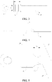
FIG. 1 is a schematic processing diagram of a connection structure of an aluminum cable and a terminal according to an embodiment of this application; -
FIG. 2 is a three-dimensional diagram of a connection structure of an aluminum cable and a terminal according to an embodiment of this application; -
FIG. 3 is a front view of a connection structure of an aluminum cable and a terminal according to an embodiment of this application; -
FIG. 4 is a side view of a connection structure of an aluminum cable and a terminal according to another embodiment of this application; and -
FIG. 5 is an unfolded schematic diagram of a connection structure of an aluminum cable and a terminal according to another embodiment of this application. - List of reference numerals:
-
Aluminum cable 10,cable core 11,cable welding portion 12,insulating sleeve 13,wave surface 14, -
terminal 20,terminal welding portion 21, crimpingportion 22, crimpingwing 23, connecting portion 24, -
welding fixture 1, andwelding head 2. - Embodiments of this application are described in detail below, and examples of the embodiments are shown in accompanying drawings, where the same or similar elements or the elements having same or similar functions are denoted by the same or similar reference numerals throughout the description. The embodiments described below with reference to the accompanying drawings are exemplary and used only for explaining this application, and should not be construed as a limitation on this application.
- In the description of this application, it should be understood that orientation or position relationships indicated by the terms such as "length", "width", "thickness", "inside", and "outside" are based on orientation or position relationships shown in the accompanying drawings, and are used only for ease and brevity of illustration and description of this application, rather than indicating or implying that the mentioned apparatus or element needs to have a particular orientation or needs to be constructed and operated in a particular orientation. Therefore, such terms should not be construed as a limitation on this application.
- The following describes a connection structure of an aluminum cable and a terminal according to the embodiments of this application with reference to the accompanying drawings.
- As shown in
FIG. 2 to FIG. 5 , the connection structure of an aluminum cable and a terminal according to the embodiments of this application includes analuminum cable 10 and aterminal 20. - The
aluminum cable 10 includes acable core 11, thecable core 11 is made of an aluminum material, and thecable core 11 is constructed with acable welding portion 12. Theterminal 20 may be a copper terminal, and for example, theterminal 20 is welded to thecable welding portion 12 in an ultrasonic welding manner. - A nominal cross-sectional area of the
cable core 11 is M, and a welding area S between thecable welding portion 12 and theterminal 20 meets 5∗M≤S≤6∗M. It may be understood that, the nominal cross-sectional area M of thecable core 11 may be understood as a cross-sectional area of thecable core 11. - The following describes a welding process of the
aluminum cable 10 and theterminal 20 according to the embodiments of this application through examples. - As shown in
FIG. 1 , an ultrasonic welding processing process mainly includes three steps: positioning, cable placing, and welding. - The
terminal 20 is first placed on a positioning block of an ultrasonic welding device, twowelding fixtures 1 on the left and right sides are movably pressed on theterminal 20, and a size between the twowelding fixtures 1 on the left and right sides is limited to be a size of awelding head 2. The cable core of thealuminum cable 10 is placed in the twowelding fixtures 1, and thewelding head 2 moves downward vertically, to weld the exposedcable core 11 of thealuminum cable 10 and theterminal 20. - It should be understood that, the
cable core 11 is generally circular in shape, the part welded by thewelding head 2 is pressed into a flat shape, namely, thecable welding portion 12, and the nominal cross-sectional area M of thecable core 11 in the embodiments of this application refers to a cross-sectional area of the circular part. - According to the connection structure of an aluminum cable and a terminal in the embodiments of this application, because the mass of the
aluminum cable 10 is 2/3 of the mass of a copper cable, and the cost of thealuminum cable 10 is 2/3 of the cost of the copper cable, objectives of cost reduction and light weight are achieved by using the connection structure of an aluminum cable and a terminal. Further, setting the welding area between thealuminum cable 10 and theterminal 20 to be 5∗M≤S≤6∗M can prevent the welding area from being excessively small or excessively large. To be specific, on one hand, if the welding area is excessively small, a high temperature is generated due to excessively concentrated welding energy, leading to overwelding and an insufficient mechanical strength after welding, finally reducing the use reliability of thealuminum cable 10. On the other hand, if the welding area is excessively small, a current allowed to pass through per square millimeter of the welding area is excessively large, a welding part may be easily burnt out, leading to a short service life of the welding part. In addition, if the welding area is excessively large, a current allowed to pass through per square millimeter of the welding area is excessively small, and the electric conduction performance of the aluminum cable is further reduced. Therefore, by setting the welding area to be 5∗M≤S≤6∗M in this application, aluminum cables in different specifications can balance the electric conduction performance, overcurrent capability, and mechanical strength. - The following tests the overcurrent capability and the welding mechanical strength of the aluminum cable by using a cable core whose nominal cross-sectional area is 50 mm2 as an example. Test results are shown in the following table:
S/M Overcurrent capability Welding mechanical strength 4.5 180 A 2500 N 5 200 A 3000 N 5.5 210 A 3200 N 6 200 A 3000 N 6.5 200 A 3000 N - As can be known from the foregoing table, when a value of S/M changes from 4.5 to 5.5, the overcurrent capability and the welding mechanical strength are both in an ascending trend, and when the value of S/M changes from 5.5 to 6.5, the overcurrent capability and the welding mechanical strength are both in a descending trend. Therefore, when the value of S/M is between 5 and 6, the aluminum cable has the optimal overcurrent capability and welding mechanical strength.
- Meanwhile, when the value of S/M exceeds 6, the overcurrent capability and the welding mechanical strength change slowly. However, when the welding area is increased, due to expansion of the welding part and control over pressure on the welding part, welding process costs are increased and a welding difficulty coefficient is increased. Therefore, limiting the welding area S between the
cable welding portion 12 and the terminal 20 to be 5∗M≤S≤6∗M can both balance the electric conduction performance, the overcurrent capability, and the mechanical strength, and control the welding difficulty coefficient and the welding process costs. - In some specific embodiments of this application, if a width of the
cable welding portion 12 corresponding to the nominal cross-sectional area M is W, a length L of thecable welding portion 12 meets 5∗M/W≤L≤6∗M/W. In other words, forcable cores 11 with different nominal cross-sectional areas, the widths of thecable welding portions 12 thereof are fixed accordingly. For example, based on USCAR-38 (ultrasonic welding standards of the Society of Automotive Engineers), the length L of thecable welding portion 12 may be set to be 5∗M/W≤L≤6∗M/W, to ensure to achieve good electric conduction performance, overcurrent capability, and mechanical strength after the cable welding portion is welded to the terminal 20. - In this application, setting the length L of the
cable welding portion 12 to be 5∗M/W≤L≤6∗M/W can prevent the length from being excessively short or excessively long. To be specific, on one hand, if the length L of thecable welding portion 12 is excessively short, the welding area is excessively small, a high temperature is generated due to excessively concentrated welding energy, leading to overwelding and an insufficient mechanical strength after welding, finally reducing the use reliability of thealuminum cable 10. On the other hand, if the length L of thecable welding portion 12 is excessively long, the length of the terminal 20 is increased, the structure of a connector to which the connection structure of an aluminum cable and a terminal is applied is re-designed, which increases design costs, as well as material costs of the terminal. - To describe the technical solutions of this application in more detail, an illustrative description is made by using the following two cables.
- For example, the nominal cross-sectional area M of the
cable core 11 is 50 mm2, the width W of the correspondingcable welding portion 12 is 16 mm, and the length L of thecable welding portion 12 meets 15.6 mm≤L≤18.8 mm. - Further, the nominal cross-sectional area M of the
cable core 11 is 70 mm2, the width W of the correspondingcable welding portion 12 is 21 mm, and the length L of thecable welding portion 12 meets 16.7 mm≤L≤20 mm. - In some specific examples of this application, as shown in
FIG. 2 , a surface of thecable welding portion 12 facing away from the terminal 20 is constructed as awave surface 14, and a peak and a valley of thewave surface 14 are distributed in a length direction of thecable welding portion 12. - As shown in
FIG. 2 , a minimum thickness H of thecable welding portion 12 is a distance between a surface of thecable welding portion 12 facing the terminal 20 and the valley, a width of thecable welding portion 12 corresponding to the nominal cross-sectional area M is W, and the minimum thickness H of thecable welding portion 12 meets 0.7∗M/W≤H≤0.8∗M/W. - Therefore, the minimum thickness H of the
cable welding portion 12 meets a compression ratio of 70% to 80%. When the minimum thickness H is less than the compression ratio of 70%, cable breaking of welding may easily occur, leading to a decrease in the electrical conductivity of thealuminum cable 10; and when the minimum thickness H is higher than the compression ratio of 80%, a risk that the welding mechanical tension strength does not reach the standard may easily occur. Further, good welding appearance can be achieved when the minimum thickness H of thecable welding portion 12 meets the compression ratio of 70% to 80%. - To describe the technical solutions of this application in more detail, an illustrative description is made by using the following cable.
- For example, the nominal cross-sectional area M of the
cable core 11 is 50 mm2, the width W of the correspondingcable welding portion 12 is 16 mm, and the minimum thickness H of thecable welding portion 12 meets 2.2 mm≤H≤2.5 mm. Therefore, the welding compression ratio of thealuminum cable 10 meets 70% to 80%. - Further, a material strength of an aluminum conductor is relatively low. To avoid cable breaking of welding caused by excessively dense waves, the
wave surface 14 adopts a welding texture with large and few waves. For example, the quantities of the peaks and the valleys of thewave surface 14 are both 2, namely, two peaks and two valleys are uniformly distributed on thewave surface 14 of thecable welding portion 12. - Still further, a maximum angle between the peak and the surface of the
cable welding portion 12 facing the terminal 20 ranges from 30° to 60°. That is, an acute angle between a tangent line of a part of the peak closest to the valley and a welding surface of thecable welding portion 12 ranges from 30° to 60°. - A maximum angle β between the valley and the surface of the
cable welding portion 12 facing the terminal 20 ranges from 30° to 60°. That is, an acute angle between a tangent line of a part of the valley closest to the peak and a welding surface of thecable welding portion 12 ranges from 30° to 60°. - A tensile strength of a cable core of a high-voltage aluminum cable used by new energy vehicles is generally from 70 MPa to 120 MPa, so that smooth transition of the welding surface of the
aluminum cable 10 can be ensured by adjusting the angles of the peak and the valley, without causing damage to a surface of thecable core 11. Therefore, a larger effective welding area is provided between thecable welding portion 12 and the terminal 20. - In some specific embodiments of this application, the
aluminum cable 10 further includes an insulatingsleeve 13. The insulatingsleeve 13 is sleeved on an outer side of thecable core 11, and thecable welding portion 12 extends out of the insulatingsleeve 13. The terminal 20 includes aterminal welding portion 21 and a crimpingportion 22, thecable welding portion 12 is welded to theterminal welding portion 21, and the crimpingportion 22 is crimped to the insulatingsleeve 13. - Specifically, as shown in
FIG. 5 , the crimpingportion 22 includes a connecting portion 24 and two crimpingwings 23. One end of the connecting portion 24 is connected with theterminal welding portion 21, and the other end of the connecting portion 24 is connected with the two crimpingwings 23. The two crimpingwings 23 clamp the insulatingsleeve 13, and the two crimpingwings 23 are staggered in a length direction of the insulatingsleeve 13. - Therefore, the crimping
portion 22 includes the two staggered crimpingwings 23, the insulatingsleeve 13 of thealuminum cable 10 is arranged running through a channel formed by the two crimpingwings 23, and the two crimpingwings 23 are crimped to an outer surface of the insulatingsleeve 13 of thealuminum cable 10 by using a crimping fixture. Therefore, the crimpingwings 23 are fixedly connected to the insulatingsleeve 13 of thealuminum cable 10, and the crimpingwings 23 can transfer mechanical stress acting on a welding region to the insulatingsleeve 13 of thealuminum cable 10, thereby effectively avoiding damage to the welding part caused by pulling thealuminum cable 10. - Further, as shown in
FIG. 4 , a thickness of the crimpingportion 22 is less than a thickness of theterminal welding portion 21, and in a radial direction of thealuminum cable 10, the crimpingportion 22 is staggered in a direction away from thealuminum cable 10 relative to theterminal welding portion 21. For example, an upper surface of the crimpingportion 22 and a lower surface of theterminal welding portion 21 lie in the same plane. In this way, a height difference of a transition region between thecable core 11 and the insulatingsleeve 13 may be adapted, thereby avoiding excessive deformation of a junction of thecable core 11 and thecable welding portion 12. - Still further, as shown in
FIG. 5 , the length of thecable welding portion 12 is L, and a length L1 of the connecting portion 24 meets 0.7L≤L1≤0.9L. In this way, the junction of thecable core 11 and thecable welding portion 12 can be prevented from being damaged when the crimpingwings 23 are crimped. - The following describes a vehicle according to an embodiment of this application. The vehicle includes the connection structure of an aluminum cable and a terminal according to the foregoing embodiments of this application.
- According to the vehicle of this embodiment of this application, advantages such as reliable electric conduction performance, a strong overcurrent capability, and a high mechanical strength can be achieved by using the connection structure of an aluminum cable and a terminal according to the foregoing embodiments of this application.
- Other configurations and operations of the vehicle according to this embodiment of this application are known to a person of ordinary skill in the art and will not be described in detail herein.
- In the description of this specification, description of reference terms such as "a specific embodiment" or "a specific example", means including specific features, structures, materials, or features described in the embodiment or example in at least one embodiment or example of this application. In this specification, exemplary descriptions of the foregoing terms do not necessarily refer to the same embodiment or example.
- Although the embodiments of this application have been shown and described, a person of ordinary skill in the art may understand that various changes, modifications, replacements, and variations may be made to the embodiments without departing from the principle and spirit of this application, and the scope of this application is as defined by the appended claims and their equivalents.
Claims (10)
- A connection structure of an aluminum cable and a terminal, comprising:an aluminum cable, comprising a cable core, wherein the cable core is constructed with a cable welding portion; anda terminal, welded to the cable welding portion, whereina nominal cross-sectional area of the cable core is M, and a welding area S between the cable welding portion and the terminal meets 5∗M≤S≤6∗M.
- The connection structure of an aluminum cable and a terminal according to claim 1, wherein if a width of the cable welding portion corresponding to the nominal cross-sectional area M is W, a length L of the cable welding portion meets 5∗M/W≤L≤6∗M/W.
- The connection structure of an aluminum cable and a terminal according to claim 1, wherein a surface of the cable welding portion facing away from the terminal is constructed as a wave surface, and a peak and a valley of the wave surface are distributed in a length direction of the cable welding portion.
- The connection structure of an aluminum cable and a terminal according to claim 3, wherein a minimum thickness H of the cable welding portion is a distance between a surface of the cable welding portion facing the terminal and the valley, a width of the cable welding portion corresponding to the nominal cross-sectional area M is W, and the minimum thickness H meets 0.7∗M/W≤H≤0.8∗M/W.
- The connection structure of an aluminum cable and a terminal according to claim 3 or 4, whereina maximum angle between the peak and the surface of the cable welding portion facing the terminal ranges from 30° to 60°; anda maximum angle β between the valley and the surface of the cable welding portion facing the terminal ranges from 30° to 60°.
- The connection structure of an aluminum cable and a terminal according to any one of claims 1 to 5, wherein the aluminum cable further comprises:an insulating sleeve, sleeved on an outer side of the cable core, wherein the cable welding portion extends out of the insulating sleeve; andthe terminal comprises a terminal welding portion and a crimping portion, the cable welding portion is welded to the terminal welding portion, and the crimping portion is crimped to the insulating sleeve.
- The connection structure of an aluminum cable and a terminal according to claim 6, wherein a thickness of the crimping portion is less than a thickness of the terminal welding portion.
- The connection structure of an aluminum cable and a terminal according to claim 6 or 7, wherein the crimping portion comprises a connecting portion and two crimping wings, one end of the connecting portion is connected with the terminal welding portion, the other end of the connecting portion is connected with the two crimping wings, and the two crimping wings clamp the insulating sleeve and are staggered in a length direction of the insulating sleeve.
- The connection structure of an aluminum cable and a terminal according to claim 8, wherein the length of the cable welding portion is L, and a length L1 of the connecting portion meets 0.7L≤L1≤0.9L.
- A vehicle, comprising the connection structure of an aluminum cable and a terminal according to any one of claims 1 to 9.
Applications Claiming Priority (2)
| Application Number | Priority Date | Filing Date | Title |
|---|---|---|---|
| CN201922114520.6U CN210985000U (en) | 2019-11-28 | 2019-11-28 | Connection structure of aluminium cable and terminal and have its vehicle |
| PCT/CN2020/132178 WO2021104436A1 (en) | 2019-11-28 | 2020-11-27 | Structure for connecting aluminum cable and terminal, and vehicle having same |
Publications (3)
| Publication Number | Publication Date |
|---|---|
| EP4068522A1 true EP4068522A1 (en) | 2022-10-05 |
| EP4068522A4 EP4068522A4 (en) | 2023-05-10 |
| EP4068522B1 EP4068522B1 (en) | 2024-05-22 |
Family
ID=71417912
Family Applications (1)
| Application Number | Title | Priority Date | Filing Date |
|---|---|---|---|
| EP20892663.4A Active EP4068522B1 (en) | 2019-11-28 | 2020-11-27 | Structure for connecting aluminum cable and terminal, and vehicle having same |
Country Status (6)
| Country | Link |
|---|---|
| US (1) | US12068564B2 (en) |
| EP (1) | EP4068522B1 (en) |
| JP (1) | JP7465967B2 (en) |
| CN (1) | CN210985000U (en) |
| ES (1) | ES2988487T3 (en) |
| WO (1) | WO2021104436A1 (en) |
Families Citing this family (1)
| Publication number | Priority date | Publication date | Assignee | Title |
|---|---|---|---|---|
| CN210985000U (en) * | 2019-11-28 | 2020-07-10 | 比亚迪股份有限公司 | Connection structure of aluminium cable and terminal and have its vehicle |
Family Cites Families (25)
| Publication number | Priority date | Publication date | Assignee | Title |
|---|---|---|---|---|
| US20080032569A1 (en) * | 2004-07-23 | 2008-02-07 | Schunk Ultraschalltechnik Gmbh | Method for Producing a Welded Joint Between Electrical Wires with a Support and Welded Joint |
| CN101151769A (en) * | 2005-04-01 | 2008-03-26 | 株式会社自动网络技术研究所 | Conductor and wire harness |
| JP2007012329A (en) | 2005-06-28 | 2007-01-18 | Hitachi Cable Ltd | Connection terminal, aluminum cable with connection terminal, ultrasonic welding method, and ultrasonic connection device |
| US7347738B2 (en) * | 2006-04-13 | 2008-03-25 | Delphi Technologies, Inc. | Low profile electrical connector assembly and terminal therefor |
| JP5660458B2 (en) * | 2010-02-16 | 2015-01-28 | 日立金属株式会社 | Electric wire with terminal and manufacturing method thereof |
| EP2683033A4 (en) * | 2011-03-02 | 2015-03-11 | Central Glass Co Ltd | Terminal structure for glass plate with conductive section and glass plate article utilizing same |
| JP2012192413A (en) * | 2011-03-15 | 2012-10-11 | Yazaki Corp | Ultrasonic joining method |
| WO2013108805A1 (en) * | 2012-01-20 | 2013-07-25 | 矢崎総業株式会社 | Ground connection structure and method for producing same |
| JP6056639B2 (en) | 2013-05-07 | 2017-01-11 | 株式会社オートネットワーク技術研究所 | Terminal, electric wire with terminal, and manufacturing method of electric wire with terminal |
| JPWO2014189054A1 (en) * | 2013-05-21 | 2017-02-23 | 矢崎総業株式会社 | Terminal bracket connection structure |
| DE102013219150A1 (en) * | 2013-09-24 | 2015-04-09 | Elringklinger Ag | Method for producing an electrically conductive connection between an electrical line and an electrically conductive component |
| JP2015135742A (en) * | 2014-01-16 | 2015-07-27 | 住友電装株式会社 | Terminal and wire connection method of the terminal |
| JP2015153604A (en) * | 2014-02-14 | 2015-08-24 | 住友電装株式会社 | Terminal and electrical connection structure for the same |
| JP2015185283A (en) * | 2014-03-20 | 2015-10-22 | 住友電装株式会社 | Terminal and electric wire connection structure of the same |
| JP2017004844A (en) | 2015-06-12 | 2017-01-05 | 株式会社フジクラ | Electric wire with terminal and manufacturing method thereof |
| EP3226353A1 (en) | 2016-03-31 | 2017-10-04 | Delphi Technologies, Inc. | Electric coupler |
| JP6776816B2 (en) | 2016-10-31 | 2020-10-28 | 住友電装株式会社 | Bonding method between core wire and object to be bonded, ultrasonic bonding device, bonding object between core wire and object to be bonded |
| CN109791815B (en) * | 2016-11-16 | 2020-08-14 | 住友电气工业株式会社 | Wire strand for wire harness and wire harness |
| EP3335827B1 (en) * | 2016-12-15 | 2019-10-09 | Aptiv Technologies Limited | Method to predict a strength of an ultrasonic weld-joint |
| CN207069080U (en) * | 2017-06-05 | 2018-03-02 | 吉林省中赢高科技有限公司 | A kind of joint of copper tip and aluminum conductor |
| JP2019129007A (en) * | 2018-01-22 | 2019-08-01 | 住友電装株式会社 | Conductive path and wire harness |
| CN110720160A (en) | 2018-05-11 | 2020-01-21 | 株式会社自动网络技术研究所 | Wire and Harness with Terminals |
| US11462842B2 (en) * | 2018-05-24 | 2022-10-04 | Autonetworks Technologies, Ltd. | Wire connection structure and wire connection method |
| DE102018119844B4 (en) * | 2018-07-26 | 2022-10-06 | Auto-Kabel Management Gmbh | Electrical connection and method of making an electrical connection |
| CN210985000U (en) * | 2019-11-28 | 2020-07-10 | 比亚迪股份有限公司 | Connection structure of aluminium cable and terminal and have its vehicle |
-
2019
- 2019-11-28 CN CN201922114520.6U patent/CN210985000U/en active Active
-
2020
- 2020-11-27 WO PCT/CN2020/132178 patent/WO2021104436A1/en not_active Ceased
- 2020-11-27 EP EP20892663.4A patent/EP4068522B1/en active Active
- 2020-11-27 JP JP2022531058A patent/JP7465967B2/en active Active
- 2020-11-27 ES ES20892663T patent/ES2988487T3/en active Active
- 2020-11-27 US US17/777,854 patent/US12068564B2/en active Active
Also Published As
| Publication number | Publication date |
|---|---|
| EP4068522B1 (en) | 2024-05-22 |
| US20230030577A1 (en) | 2023-02-02 |
| WO2021104436A1 (en) | 2021-06-03 |
| US12068564B2 (en) | 2024-08-20 |
| JP7465967B2 (en) | 2024-04-11 |
| CN210985000U (en) | 2020-07-10 |
| JP2023503495A (en) | 2023-01-30 |
| ES2988487T3 (en) | 2024-11-20 |
| EP4068522A4 (en) | 2023-05-10 |
Similar Documents
| Publication | Publication Date | Title |
|---|---|---|
| US10446956B2 (en) | Flexible circuits for electrical harnesses | |
| US9099793B2 (en) | Crimping structure of terminal to electrical cable | |
| EP4261848A1 (en) | Flexible aluminum conductive wire body, conductive piece, and car | |
| EP4068522B1 (en) | Structure for connecting aluminum cable and terminal, and vehicle having same | |
| EP4496153A1 (en) | Electric energy transmission assembly and vehicle | |
| US20130231012A1 (en) | Crimping Sleeve for Crimped Connections | |
| CN107453182A (en) | The manufacture method of electric wire with terminal | |
| EP4496144A1 (en) | Connector assembly and processing method | |
| EP4495957A1 (en) | Electric energy transmission system and automobile | |
| KR102735965B1 (en) | Aluminum components for electrical energy transmission and their processing processes | |
| JP5128523B2 (en) | Crimp terminal for high strength thin wire | |
| CN206834349U (en) | The special crimp type terminal of aluminum electric wire | |
| US20110302763A1 (en) | Device for attaching a line to a connecting element | |
| CN109103725A (en) | The Joining Technology and connection structure of cable and terminal | |
| CN209880875U (en) | Connecting terminal and pressing die | |
| CN221826643U (en) | Tensile detection device for wire harness terminal | |
| CN111883952B (en) | Flat cable with good conductivity | |
| WO2022088755A1 (en) | Circuit carrying board, power distribution unit, and device | |
| CN207052789U (en) | Connecting line and electric connector terminal | |
| CN207052911U (en) | Connecting line and electric connector terminal | |
| WO2019087731A1 (en) | Pipe conductor and conductive path | |
| CN220492223U (en) | Electric connecting device | |
| CN223415182U (en) | Patch device | |
| CN223141039U (en) | Connecting wire and connecting terminal thereof | |
| CN222720663U (en) | Copper-aluminum wire connection structure with good stability |
Legal Events
| Date | Code | Title | Description |
|---|---|---|---|
| STAA | Information on the status of an ep patent application or granted ep patent |
Free format text: STATUS: THE INTERNATIONAL PUBLICATION HAS BEEN MADE |
|
| PUAI | Public reference made under article 153(3) epc to a published international application that has entered the european phase |
Free format text: ORIGINAL CODE: 0009012 |
|
| STAA | Information on the status of an ep patent application or granted ep patent |
Free format text: STATUS: REQUEST FOR EXAMINATION WAS MADE |
|
| 17P | Request for examination filed |
Effective date: 20220627 |
|
| AK | Designated contracting states |
Kind code of ref document: A1 Designated state(s): AL AT BE BG CH CY CZ DE DK EE ES FI FR GB GR HR HU IE IS IT LI LT LU LV MC MK MT NL NO PL PT RO RS SE SI SK SM TR |
|
| DAV | Request for validation of the european patent (deleted) | ||
| DAX | Request for extension of the european patent (deleted) | ||
| REG | Reference to a national code |
Ref country code: DE Free format text: PREVIOUS MAIN CLASS: H01R0011120000 Ipc: H01R0004020000 Ref legal event code: R079 Ref document number: 602020031443 Country of ref document: DE |
|
| A4 | Supplementary search report drawn up and despatched |
Effective date: 20230406 |
|
| RIC1 | Information provided on ipc code assigned before grant |
Ipc: H01R 11/12 20060101ALN20230331BHEP Ipc: H01R 43/02 20060101ALN20230331BHEP Ipc: H01R 4/62 20060101ALI20230331BHEP Ipc: H01R 4/02 20060101AFI20230331BHEP |
|
| GRAP | Despatch of communication of intention to grant a patent |
Free format text: ORIGINAL CODE: EPIDOSNIGR1 |
|
| STAA | Information on the status of an ep patent application or granted ep patent |
Free format text: STATUS: GRANT OF PATENT IS INTENDED |
|
| RIC1 | Information provided on ipc code assigned before grant |
Ipc: H01R 11/12 20060101ALN20231129BHEP Ipc: H01R 43/02 20060101ALN20231129BHEP Ipc: H01R 4/62 20060101ALI20231129BHEP Ipc: H01R 4/02 20060101AFI20231129BHEP |
|
| INTG | Intention to grant announced |
Effective date: 20231215 |
|
| GRAS | Grant fee paid |
Free format text: ORIGINAL CODE: EPIDOSNIGR3 |
|
| GRAA | (expected) grant |
Free format text: ORIGINAL CODE: 0009210 |
|
| STAA | Information on the status of an ep patent application or granted ep patent |
Free format text: STATUS: THE PATENT HAS BEEN GRANTED |
|
| AK | Designated contracting states |
Kind code of ref document: B1 Designated state(s): AL AT BE BG CH CY CZ DE DK EE ES FI FR GB GR HR HU IE IS IT LI LT LU LV MC MK MT NL NO PL PT RO RS SE SI SK SM TR |
|
| REG | Reference to a national code |
Ref country code: GB Ref legal event code: FG4D |
|
| REG | Reference to a national code |
Ref country code: CH Ref legal event code: EP |
|
| REG | Reference to a national code |
Ref country code: DE Ref legal event code: R096 Ref document number: 602020031443 Country of ref document: DE |
|
| REG | Reference to a national code |
Ref country code: IE Ref legal event code: FG4D |
|
| REG | Reference to a national code |
Ref country code: NL Ref legal event code: FP |
|
| REG | Reference to a national code |
Ref country code: LT Ref legal event code: MG9D |
|
| PG25 | Lapsed in a contracting state [announced via postgrant information from national office to epo] |
Ref country code: IS Free format text: LAPSE BECAUSE OF FAILURE TO SUBMIT A TRANSLATION OF THE DESCRIPTION OR TO PAY THE FEE WITHIN THE PRESCRIBED TIME-LIMIT Effective date: 20240922 |
|
| PG25 | Lapsed in a contracting state [announced via postgrant information from national office to epo] |
Ref country code: BG Free format text: LAPSE BECAUSE OF FAILURE TO SUBMIT A TRANSLATION OF THE DESCRIPTION OR TO PAY THE FEE WITHIN THE PRESCRIBED TIME-LIMIT Effective date: 20240522 |
|
| PG25 | Lapsed in a contracting state [announced via postgrant information from national office to epo] |
Ref country code: FI Free format text: LAPSE BECAUSE OF FAILURE TO SUBMIT A TRANSLATION OF THE DESCRIPTION OR TO PAY THE FEE WITHIN THE PRESCRIBED TIME-LIMIT Effective date: 20240522 Ref country code: HR Free format text: LAPSE BECAUSE OF FAILURE TO SUBMIT A TRANSLATION OF THE DESCRIPTION OR TO PAY THE FEE WITHIN THE PRESCRIBED TIME-LIMIT Effective date: 20240522 |
|
| PG25 | Lapsed in a contracting state [announced via postgrant information from national office to epo] |
Ref country code: GR Free format text: LAPSE BECAUSE OF FAILURE TO SUBMIT A TRANSLATION OF THE DESCRIPTION OR TO PAY THE FEE WITHIN THE PRESCRIBED TIME-LIMIT Effective date: 20240823 |
|
| PG25 | Lapsed in a contracting state [announced via postgrant information from national office to epo] |
Ref country code: PT Free format text: LAPSE BECAUSE OF FAILURE TO SUBMIT A TRANSLATION OF THE DESCRIPTION OR TO PAY THE FEE WITHIN THE PRESCRIBED TIME-LIMIT Effective date: 20240923 |
|
| REG | Reference to a national code |
Ref country code: AT Ref legal event code: MK05 Ref document number: 1689540 Country of ref document: AT Kind code of ref document: T Effective date: 20240522 |
|
| P01 | Opt-out of the competence of the unified patent court (upc) registered |
Free format text: CASE NUMBER: APP_51322/2024 Effective date: 20240911 |
|
| PG25 | Lapsed in a contracting state [announced via postgrant information from national office to epo] |
Ref country code: AT Free format text: LAPSE BECAUSE OF FAILURE TO SUBMIT A TRANSLATION OF THE DESCRIPTION OR TO PAY THE FEE WITHIN THE PRESCRIBED TIME-LIMIT Effective date: 20240522 |
|
| PG25 | Lapsed in a contracting state [announced via postgrant information from national office to epo] |
Ref country code: PL Free format text: LAPSE BECAUSE OF FAILURE TO SUBMIT A TRANSLATION OF THE DESCRIPTION OR TO PAY THE FEE WITHIN THE PRESCRIBED TIME-LIMIT Effective date: 20240522 |
|
| PG25 | Lapsed in a contracting state [announced via postgrant information from national office to epo] |
Ref country code: LV Free format text: LAPSE BECAUSE OF FAILURE TO SUBMIT A TRANSLATION OF THE DESCRIPTION OR TO PAY THE FEE WITHIN THE PRESCRIBED TIME-LIMIT Effective date: 20240522 |
|
| PG25 | Lapsed in a contracting state [announced via postgrant information from national office to epo] |
Ref country code: PT Free format text: LAPSE BECAUSE OF FAILURE TO SUBMIT A TRANSLATION OF THE DESCRIPTION OR TO PAY THE FEE WITHIN THE PRESCRIBED TIME-LIMIT Effective date: 20240923 Ref country code: PL Free format text: LAPSE BECAUSE OF FAILURE TO SUBMIT A TRANSLATION OF THE DESCRIPTION OR TO PAY THE FEE WITHIN THE PRESCRIBED TIME-LIMIT Effective date: 20240522 Ref country code: LV Free format text: LAPSE BECAUSE OF FAILURE TO SUBMIT A TRANSLATION OF THE DESCRIPTION OR TO PAY THE FEE WITHIN THE PRESCRIBED TIME-LIMIT Effective date: 20240522 Ref country code: IS Free format text: LAPSE BECAUSE OF FAILURE TO SUBMIT A TRANSLATION OF THE DESCRIPTION OR TO PAY THE FEE WITHIN THE PRESCRIBED TIME-LIMIT Effective date: 20240922 Ref country code: HR Free format text: LAPSE BECAUSE OF FAILURE TO SUBMIT A TRANSLATION OF THE DESCRIPTION OR TO PAY THE FEE WITHIN THE PRESCRIBED TIME-LIMIT Effective date: 20240522 Ref country code: GR Free format text: LAPSE BECAUSE OF FAILURE TO SUBMIT A TRANSLATION OF THE DESCRIPTION OR TO PAY THE FEE WITHIN THE PRESCRIBED TIME-LIMIT Effective date: 20240823 Ref country code: FI Free format text: LAPSE BECAUSE OF FAILURE TO SUBMIT A TRANSLATION OF THE DESCRIPTION OR TO PAY THE FEE WITHIN THE PRESCRIBED TIME-LIMIT Effective date: 20240522 Ref country code: BG Free format text: LAPSE BECAUSE OF FAILURE TO SUBMIT A TRANSLATION OF THE DESCRIPTION OR TO PAY THE FEE WITHIN THE PRESCRIBED TIME-LIMIT Effective date: 20240522 Ref country code: AT Free format text: LAPSE BECAUSE OF FAILURE TO SUBMIT A TRANSLATION OF THE DESCRIPTION OR TO PAY THE FEE WITHIN THE PRESCRIBED TIME-LIMIT Effective date: 20240522 Ref country code: RS Free format text: LAPSE BECAUSE OF FAILURE TO SUBMIT A TRANSLATION OF THE DESCRIPTION OR TO PAY THE FEE WITHIN THE PRESCRIBED TIME-LIMIT Effective date: 20240822 |
|
| REG | Reference to a national code |
Ref country code: ES Ref legal event code: FG2A Ref document number: 2988487 Country of ref document: ES Kind code of ref document: T3 Effective date: 20241120 |
|
| PG25 | Lapsed in a contracting state [announced via postgrant information from national office to epo] |
Ref country code: DK Free format text: LAPSE BECAUSE OF FAILURE TO SUBMIT A TRANSLATION OF THE DESCRIPTION OR TO PAY THE FEE WITHIN THE PRESCRIBED TIME-LIMIT Effective date: 20240522 |
|
| PG25 | Lapsed in a contracting state [announced via postgrant information from national office to epo] |
Ref country code: EE Free format text: LAPSE BECAUSE OF FAILURE TO SUBMIT A TRANSLATION OF THE DESCRIPTION OR TO PAY THE FEE WITHIN THE PRESCRIBED TIME-LIMIT Effective date: 20240522 |
|
| PG25 | Lapsed in a contracting state [announced via postgrant information from national office to epo] |
Ref country code: CZ Free format text: LAPSE BECAUSE OF FAILURE TO SUBMIT A TRANSLATION OF THE DESCRIPTION OR TO PAY THE FEE WITHIN THE PRESCRIBED TIME-LIMIT Effective date: 20240522 |
|
| PG25 | Lapsed in a contracting state [announced via postgrant information from national office to epo] |
Ref country code: SK Free format text: LAPSE BECAUSE OF FAILURE TO SUBMIT A TRANSLATION OF THE DESCRIPTION OR TO PAY THE FEE WITHIN THE PRESCRIBED TIME-LIMIT Effective date: 20240522 Ref country code: RO Free format text: LAPSE BECAUSE OF FAILURE TO SUBMIT A TRANSLATION OF THE DESCRIPTION OR TO PAY THE FEE WITHIN THE PRESCRIBED TIME-LIMIT Effective date: 20240522 |
|
| PG25 | Lapsed in a contracting state [announced via postgrant information from national office to epo] |
Ref country code: SK Free format text: LAPSE BECAUSE OF FAILURE TO SUBMIT A TRANSLATION OF THE DESCRIPTION OR TO PAY THE FEE WITHIN THE PRESCRIBED TIME-LIMIT Effective date: 20240522 Ref country code: RO Free format text: LAPSE BECAUSE OF FAILURE TO SUBMIT A TRANSLATION OF THE DESCRIPTION OR TO PAY THE FEE WITHIN THE PRESCRIBED TIME-LIMIT Effective date: 20240522 Ref country code: EE Free format text: LAPSE BECAUSE OF FAILURE TO SUBMIT A TRANSLATION OF THE DESCRIPTION OR TO PAY THE FEE WITHIN THE PRESCRIBED TIME-LIMIT Effective date: 20240522 Ref country code: DK Free format text: LAPSE BECAUSE OF FAILURE TO SUBMIT A TRANSLATION OF THE DESCRIPTION OR TO PAY THE FEE WITHIN THE PRESCRIBED TIME-LIMIT Effective date: 20240522 Ref country code: CZ Free format text: LAPSE BECAUSE OF FAILURE TO SUBMIT A TRANSLATION OF THE DESCRIPTION OR TO PAY THE FEE WITHIN THE PRESCRIBED TIME-LIMIT Effective date: 20240522 |
|
| REG | Reference to a national code |
Ref country code: DE Ref legal event code: R097 Ref document number: 602020031443 Country of ref document: DE |
|
| PLBE | No opposition filed within time limit |
Free format text: ORIGINAL CODE: 0009261 |
|
| STAA | Information on the status of an ep patent application or granted ep patent |
Free format text: STATUS: NO OPPOSITION FILED WITHIN TIME LIMIT |
|
| PG25 | Lapsed in a contracting state [announced via postgrant information from national office to epo] |
Ref country code: SI Free format text: LAPSE BECAUSE OF FAILURE TO SUBMIT A TRANSLATION OF THE DESCRIPTION OR TO PAY THE FEE WITHIN THE PRESCRIBED TIME-LIMIT Effective date: 20240522 |
|
| 26N | No opposition filed |
Effective date: 20250225 |
|
| REG | Reference to a national code |
Ref country code: CH Ref legal event code: PL |
|
| PG25 | Lapsed in a contracting state [announced via postgrant information from national office to epo] |
Ref country code: MC Free format text: LAPSE BECAUSE OF FAILURE TO SUBMIT A TRANSLATION OF THE DESCRIPTION OR TO PAY THE FEE WITHIN THE PRESCRIBED TIME-LIMIT Effective date: 20240522 |
|
| PG25 | Lapsed in a contracting state [announced via postgrant information from national office to epo] |
Ref country code: LU Free format text: LAPSE BECAUSE OF NON-PAYMENT OF DUE FEES Effective date: 20241127 |
|
| REG | Reference to a national code |
Ref country code: CH Ref legal event code: PL |
|
| PG25 | Lapsed in a contracting state [announced via postgrant information from national office to epo] |
Ref country code: CH Free format text: LAPSE BECAUSE OF NON-PAYMENT OF DUE FEES Effective date: 20241130 |
|
| REG | Reference to a national code |
Ref country code: BE Ref legal event code: MM Effective date: 20241130 |
|
| PG25 | Lapsed in a contracting state [announced via postgrant information from national office to epo] |
Ref country code: SE Free format text: LAPSE BECAUSE OF FAILURE TO SUBMIT A TRANSLATION OF THE DESCRIPTION OR TO PAY THE FEE WITHIN THE PRESCRIBED TIME-LIMIT Effective date: 20240522 |
|
| PG25 | Lapsed in a contracting state [announced via postgrant information from national office to epo] |
Ref country code: BE Free format text: LAPSE BECAUSE OF NON-PAYMENT OF DUE FEES Effective date: 20241130 |
|
| PG25 | Lapsed in a contracting state [announced via postgrant information from national office to epo] |
Ref country code: IE Free format text: LAPSE BECAUSE OF NON-PAYMENT OF DUE FEES Effective date: 20241127 |
|
| PGFP | Annual fee paid to national office [announced via postgrant information from national office to epo] |
Ref country code: NL Payment date: 20251119 Year of fee payment: 6 |
|
| PGFP | Annual fee paid to national office [announced via postgrant information from national office to epo] |
Ref country code: DE Payment date: 20251118 Year of fee payment: 6 |
|
| PGFP | Annual fee paid to national office [announced via postgrant information from national office to epo] |
Ref country code: GB Payment date: 20251120 Year of fee payment: 6 |
|
| PGFP | Annual fee paid to national office [announced via postgrant information from national office to epo] |
Ref country code: NO Payment date: 20251125 Year of fee payment: 6 |
|
| PGFP | Annual fee paid to national office [announced via postgrant information from national office to epo] |
Ref country code: IT Payment date: 20251125 Year of fee payment: 6 |
|
| PGFP | Annual fee paid to national office [announced via postgrant information from national office to epo] |
Ref country code: FR Payment date: 20251120 Year of fee payment: 6 |
|
| PGFP | Annual fee paid to national office [announced via postgrant information from national office to epo] |
Ref country code: ES Payment date: 20251229 Year of fee payment: 6 |
|
| PG25 | Lapsed in a contracting state [announced via postgrant information from national office to epo] |
Ref country code: HU Free format text: LAPSE BECAUSE OF FAILURE TO SUBMIT A TRANSLATION OF THE DESCRIPTION OR TO PAY THE FEE WITHIN THE PRESCRIBED TIME-LIMIT; INVALID AB INITIO Effective date: 20201127 |
|
| PG25 | Lapsed in a contracting state [announced via postgrant information from national office to epo] |
Ref country code: CY Free format text: LAPSE BECAUSE OF FAILURE TO SUBMIT A TRANSLATION OF THE DESCRIPTION OR TO PAY THE FEE WITHIN THE PRESCRIBED TIME-LIMIT; INVALID AB INITIO Effective date: 20201127 |
|
| PG25 | Lapsed in a contracting state [announced via postgrant information from national office to epo] |
Ref country code: SM Free format text: LAPSE BECAUSE OF FAILURE TO SUBMIT A TRANSLATION OF THE DESCRIPTION OR TO PAY THE FEE WITHIN THE PRESCRIBED TIME-LIMIT; INVALID AB INITIO Effective date: 20201127 |