EP4068495A1 - Battery and terminal device - Google Patents
Battery and terminal device Download PDFInfo
- Publication number
- EP4068495A1 EP4068495A1 EP20906288.4A EP20906288A EP4068495A1 EP 4068495 A1 EP4068495 A1 EP 4068495A1 EP 20906288 A EP20906288 A EP 20906288A EP 4068495 A1 EP4068495 A1 EP 4068495A1
- Authority
- EP
- European Patent Office
- Prior art keywords
- electrode
- tabs
- disposed
- edge
- blank area
- Prior art date
- Legal status (The legal status is an assumption and is not a legal conclusion. Google has not performed a legal analysis and makes no representation as to the accuracy of the status listed.)
- Pending
Links
- 238000007599 discharging Methods 0.000 claims abstract description 120
- 238000004804 winding Methods 0.000 claims abstract description 33
- WHXSMMKQMYFTQS-UHFFFAOYSA-N Lithium Chemical compound [Li] WHXSMMKQMYFTQS-UHFFFAOYSA-N 0.000 claims abstract description 14
- 229910052744 lithium Inorganic materials 0.000 claims abstract description 14
- 238000007747 plating Methods 0.000 claims abstract description 14
- 239000007772 electrode material Substances 0.000 claims description 30
- YWXYYJSYQOXTPL-SLPGGIOYSA-N isosorbide mononitrate Chemical compound [O-][N+](=O)O[C@@H]1CO[C@@H]2[C@@H](O)CO[C@@H]21 YWXYYJSYQOXTPL-SLPGGIOYSA-N 0.000 claims description 21
- 238000005452 bending Methods 0.000 claims description 19
- 238000000034 method Methods 0.000 claims description 15
- 238000000926 separation method Methods 0.000 claims description 10
- 230000017525 heat dissipation Effects 0.000 abstract description 13
- 230000006866 deterioration Effects 0.000 abstract description 8
- 238000005516 engineering process Methods 0.000 abstract description 3
- 238000010586 diagram Methods 0.000 description 43
- 235000015110 jellies Nutrition 0.000 description 14
- 239000008274 jelly Substances 0.000 description 14
- 239000000243 solution Substances 0.000 description 7
- 238000004891 communication Methods 0.000 description 6
- 239000010949 copper Substances 0.000 description 4
- 239000000463 material Substances 0.000 description 4
- RYGMFSIKBFXOCR-UHFFFAOYSA-N Copper Chemical group [Cu] RYGMFSIKBFXOCR-UHFFFAOYSA-N 0.000 description 3
- PXHVJJICTQNCMI-UHFFFAOYSA-N Nickel Chemical compound [Ni] PXHVJJICTQNCMI-UHFFFAOYSA-N 0.000 description 3
- 229910052802 copper Inorganic materials 0.000 description 3
- 230000008569 process Effects 0.000 description 3
- 238000003466 welding Methods 0.000 description 3
- 229910052782 aluminium Inorganic materials 0.000 description 2
- XAGFODPZIPBFFR-UHFFFAOYSA-N aluminium Chemical compound [Al] XAGFODPZIPBFFR-UHFFFAOYSA-N 0.000 description 2
- 230000003190 augmentative effect Effects 0.000 description 2
- 238000006243 chemical reaction Methods 0.000 description 2
- 239000011888 foil Substances 0.000 description 2
- 230000006870 function Effects 0.000 description 2
- 229910000625 lithium cobalt oxide Inorganic materials 0.000 description 2
- BFZPBUKRYWOWDV-UHFFFAOYSA-N lithium;oxido(oxo)cobalt Chemical compound [Li+].[O-][Co]=O BFZPBUKRYWOWDV-UHFFFAOYSA-N 0.000 description 2
- 229910032387 LiCoO2 Inorganic materials 0.000 description 1
- HBBGRARXTFLTSG-UHFFFAOYSA-N Lithium ion Chemical compound [Li+] HBBGRARXTFLTSG-UHFFFAOYSA-N 0.000 description 1
- 229910018054 Ni-Cu Inorganic materials 0.000 description 1
- 229910018481 Ni—Cu Inorganic materials 0.000 description 1
- 239000010405 anode material Substances 0.000 description 1
- 230000005540 biological transmission Effects 0.000 description 1
- 230000015572 biosynthetic process Effects 0.000 description 1
- 239000003575 carbonaceous material Substances 0.000 description 1
- 239000010406 cathode material Substances 0.000 description 1
- 230000008859 change Effects 0.000 description 1
- 238000005352 clarification Methods 0.000 description 1
- 150000001875 compounds Chemical class 0.000 description 1
- 239000004020 conductor Substances 0.000 description 1
- 238000009826 distribution Methods 0.000 description 1
- 239000003792 electrolyte Substances 0.000 description 1
- 239000004744 fabric Substances 0.000 description 1
- 239000007924 injection Substances 0.000 description 1
- 238000002347 injection Methods 0.000 description 1
- 230000003993 interaction Effects 0.000 description 1
- 230000002687 intercalation Effects 0.000 description 1
- 238000009830 intercalation Methods 0.000 description 1
- 150000002500 ions Chemical class 0.000 description 1
- 239000007788 liquid Substances 0.000 description 1
- 229910001416 lithium ion Inorganic materials 0.000 description 1
- 238000004519 manufacturing process Methods 0.000 description 1
- 229910052751 metal Inorganic materials 0.000 description 1
- 239000002184 metal Substances 0.000 description 1
- 239000000203 mixture Substances 0.000 description 1
- 229910052759 nickel Inorganic materials 0.000 description 1
- 238000005457 optimization Methods 0.000 description 1
- 238000013021 overheating Methods 0.000 description 1
- 238000004806 packaging method and process Methods 0.000 description 1
- BASFCYQUMIYNBI-UHFFFAOYSA-N platinum Chemical compound [Pt] BASFCYQUMIYNBI-UHFFFAOYSA-N 0.000 description 1
- 238000007789 sealing Methods 0.000 description 1
- 239000007787 solid Substances 0.000 description 1
- 239000000126 substance Substances 0.000 description 1
Images












Classifications
-
- H—ELECTRICITY
- H01—ELECTRIC ELEMENTS
- H01M—PROCESSES OR MEANS, e.g. BATTERIES, FOR THE DIRECT CONVERSION OF CHEMICAL ENERGY INTO ELECTRICAL ENERGY
- H01M4/00—Electrodes
- H01M4/02—Electrodes composed of, or comprising, active material
- H01M4/13—Electrodes for accumulators with non-aqueous electrolyte, e.g. for lithium-accumulators; Processes of manufacture thereof
- H01M4/131—Electrodes based on mixed oxides or hydroxides, or on mixtures of oxides or hydroxides, e.g. LiCoOx
-
- H—ELECTRICITY
- H01—ELECTRIC ELEMENTS
- H01M—PROCESSES OR MEANS, e.g. BATTERIES, FOR THE DIRECT CONVERSION OF CHEMICAL ENERGY INTO ELECTRICAL ENERGY
- H01M50/00—Constructional details or processes of manufacture of the non-active parts of electrochemical cells other than fuel cells, e.g. hybrid cells
- H01M50/50—Current conducting connections for cells or batteries
- H01M50/543—Terminals
- H01M50/547—Terminals characterised by the disposition of the terminals on the cells
-
- H—ELECTRICITY
- H01—ELECTRIC ELEMENTS
- H01M—PROCESSES OR MEANS, e.g. BATTERIES, FOR THE DIRECT CONVERSION OF CHEMICAL ENERGY INTO ELECTRICAL ENERGY
- H01M10/00—Secondary cells; Manufacture thereof
- H01M10/04—Construction or manufacture in general
- H01M10/0431—Cells with wound or folded electrodes
-
- H—ELECTRICITY
- H01—ELECTRIC ELEMENTS
- H01M—PROCESSES OR MEANS, e.g. BATTERIES, FOR THE DIRECT CONVERSION OF CHEMICAL ENERGY INTO ELECTRICAL ENERGY
- H01M10/00—Secondary cells; Manufacture thereof
- H01M10/05—Accumulators with non-aqueous electrolyte
- H01M10/058—Construction or manufacture
- H01M10/0587—Construction or manufacture of accumulators having only wound construction elements, i.e. wound positive electrodes, wound negative electrodes and wound separators
-
- H—ELECTRICITY
- H01—ELECTRIC ELEMENTS
- H01M—PROCESSES OR MEANS, e.g. BATTERIES, FOR THE DIRECT CONVERSION OF CHEMICAL ENERGY INTO ELECTRICAL ENERGY
- H01M4/00—Electrodes
- H01M4/02—Electrodes composed of, or comprising, active material
- H01M4/13—Electrodes for accumulators with non-aqueous electrolyte, e.g. for lithium-accumulators; Processes of manufacture thereof
- H01M4/133—Electrodes based on carbonaceous material, e.g. graphite-intercalation compounds or CFx
-
- H—ELECTRICITY
- H01—ELECTRIC ELEMENTS
- H01M—PROCESSES OR MEANS, e.g. BATTERIES, FOR THE DIRECT CONVERSION OF CHEMICAL ENERGY INTO ELECTRICAL ENERGY
- H01M50/00—Constructional details or processes of manufacture of the non-active parts of electrochemical cells other than fuel cells, e.g. hybrid cells
- H01M50/50—Current conducting connections for cells or batteries
- H01M50/531—Electrode connections inside a battery casing
- H01M50/533—Electrode connections inside a battery casing characterised by the shape of the leads or tabs
-
- H—ELECTRICITY
- H01—ELECTRIC ELEMENTS
- H01M—PROCESSES OR MEANS, e.g. BATTERIES, FOR THE DIRECT CONVERSION OF CHEMICAL ENERGY INTO ELECTRICAL ENERGY
- H01M50/00—Constructional details or processes of manufacture of the non-active parts of electrochemical cells other than fuel cells, e.g. hybrid cells
- H01M50/50—Current conducting connections for cells or batteries
- H01M50/531—Electrode connections inside a battery casing
- H01M50/538—Connection of several leads or tabs of wound or folded electrode stacks
-
- H—ELECTRICITY
- H01—ELECTRIC ELEMENTS
- H01M—PROCESSES OR MEANS, e.g. BATTERIES, FOR THE DIRECT CONVERSION OF CHEMICAL ENERGY INTO ELECTRICAL ENERGY
- H01M50/00—Constructional details or processes of manufacture of the non-active parts of electrochemical cells other than fuel cells, e.g. hybrid cells
- H01M50/50—Current conducting connections for cells or batteries
- H01M50/543—Terminals
- H01M50/552—Terminals characterised by their shape
- H01M50/553—Terminals adapted for prismatic, pouch or rectangular cells
- H01M50/557—Plate-shaped terminals
-
- H—ELECTRICITY
- H01—ELECTRIC ELEMENTS
- H01M—PROCESSES OR MEANS, e.g. BATTERIES, FOR THE DIRECT CONVERSION OF CHEMICAL ENERGY INTO ELECTRICAL ENERGY
- H01M2220/00—Batteries for particular applications
- H01M2220/30—Batteries in portable systems, e.g. mobile phone, laptop
-
- Y—GENERAL TAGGING OF NEW TECHNOLOGICAL DEVELOPMENTS; GENERAL TAGGING OF CROSS-SECTIONAL TECHNOLOGIES SPANNING OVER SEVERAL SECTIONS OF THE IPC; TECHNICAL SUBJECTS COVERED BY FORMER USPC CROSS-REFERENCE ART COLLECTIONS [XRACs] AND DIGESTS
- Y02—TECHNOLOGIES OR APPLICATIONS FOR MITIGATION OR ADAPTATION AGAINST CLIMATE CHANGE
- Y02E—REDUCTION OF GREENHOUSE GAS [GHG] EMISSIONS, RELATED TO ENERGY GENERATION, TRANSMISSION OR DISTRIBUTION
- Y02E60/00—Enabling technologies; Technologies with a potential or indirect contribution to GHG emissions mitigation
- Y02E60/10—Energy storage using batteries
-
- Y—GENERAL TAGGING OF NEW TECHNOLOGICAL DEVELOPMENTS; GENERAL TAGGING OF CROSS-SECTIONAL TECHNOLOGIES SPANNING OVER SEVERAL SECTIONS OF THE IPC; TECHNICAL SUBJECTS COVERED BY FORMER USPC CROSS-REFERENCE ART COLLECTIONS [XRACs] AND DIGESTS
- Y02—TECHNOLOGIES OR APPLICATIONS FOR MITIGATION OR ADAPTATION AGAINST CLIMATE CHANGE
- Y02P—CLIMATE CHANGE MITIGATION TECHNOLOGIES IN THE PRODUCTION OR PROCESSING OF GOODS
- Y02P70/00—Climate change mitigation technologies in the production process for final industrial or consumer products
- Y02P70/50—Manufacturing or production processes characterised by the final manufactured product
Definitions
- Embodiments of this application relate to the field of terminal device battery technologies, and in particular, to a battery and a terminal device.
- a terminal device for example, a mobile phone or a tablet
- power consumption of the terminal device is significantly increased, and consequently a battery of the terminal drains increasingly sooner.
- a conventional battery is charged slowly, and consequently user experience is seriously affected.
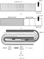
- a battery including an electrochemical cell shown in (d) in FIG. 1A and FIG. 1B is used as an example.
- (c) in FIG. 1A and FIG. 1B is a sectional view of an inner-ring jelly roll of the electrochemical cell shown in (d) in FIG. 1A and FIG. 1B .
- the jelly roll corresponding to (c) in FIG. 1A and FIG. 1B is obtained by winding a first electrode shown in (a) in FIG. 1A and FIG. 1B and a second electrode shown in (b) in FIG. 1A and FIG. 1B .
- a charging speed of the conventional battery shown in (d) in FIG. 1A and FIG. 1B is difficult to continuously increase because of the following two factors: 1.
- a tab is usually disposed on the right edge of the electrode (as shown in (a) in FIG. 1A and FIG. 1B and (b) in FIG. 1A and FIG. 1B ). Consequently, charging current transmission efficiency is low, and the charging speed is slow.
- the conventional battery has only one first tab (for example, an anode tab) and only one second tab (for example, a cathode tab), and consequently only one charging link can be provided.
- a capability of one charging link to withstand a large current is limited, and consequently a charging current of the battery cannot be continuously increased.
- the foregoing two factors cause a bottleneck, where the charging speed of the conventional battery is difficult to continuously increase.
- This application provides a battery and a terminal device, to increase a fast charging capability, and relieve heat dissipation pressure of a charging/discharging link.
- a battery includes a multi-tab electrochemical cell, and the multi-tab electrochemical cell is obtained by winding a first electrode, a second electrode, and a separator used to separate the first electrode from the second electrode.
- the first electrode includes at least one first blank area, and m first tabs are disposed on the at least one first blank area; the second electrode includes at least one second blank area, and n second tabs are disposed on the at least one second blank area; and m and n are positive integers, m ⁇ 1, n ⁇ 1, and m and n are not equal to 1 at the same time.
- the at least one first blank area and the at least one second blank area each include at least one non-edge blank area.
- At least two tabs are disposed on at least one of the at least one first blank area and the at least one second blank area, at least one of the at least two tabs protrudes from a first side of a corresponding electrode, and at least one of the at least two tabs protrudes from a second side of the corresponding electrode; and the first side is a first long side of the corresponding electrode, and the second side is a second long side of the corresponding electrode.
- the blank area is an area in which a current collector is not coated with an electrode material.
- the battery having at least two ports is obtained by winding a first electrode and a second electrode that have a novel structure (for example, a plurality of tabs separately protrude from a first long side and a second long side of an electrode, and the tabs are disposed on a non-edge area).
- the battery and another charging/discharging component may form at least two charging/discharging links, to increase a fast charging capability, and relieve heat dissipation pressure of each charging/discharging link.
- stress inside the battery is evenly distributed, so that interface deterioration of the electrode that is caused by stress unevenness can be alleviated. This effectively reduces a risk of shading and lithium plating generated in a cathode charging/discharging cycle, and improves performance of the battery.
- the at least one first blank area includes i 1 non-edge first blank areas, and the m first tabs are disposed on the i 1 non-edge first blank areas; the at least one second blank area includes j 1 non-edge second blank areas, and the n second tabs are disposed on the j 1 non-edge second blank areas; and i 1 and j 1 are positive integers.
- the battery having at least two ports is obtained by winding a first electrode on which a plurality of tabs are disposed in the middle and separately protrude from a first long side and a second long side of an electrode, and a second electrode on which a plurality of tabs are disposed in the middle and separately protrude from a first long side and a second long side of an electrode.
- the battery and another charging/discharging component may form at least two charging/discharging links, to increase a fast charging capability, and relieve heat dissipation pressure of each charging/discharging link.
- stress inside the battery is evenly distributed, so that interface deterioration of the electrode that is caused by stress unevenness can be alleviated. This effectively reduces a risk of shading and lithium plating generated in a cathode charging/discharging cycle, and improves performance of the battery.
- the at least one first blank area includes i 2 non-edge first blank areas, the m first tabs are disposed on the i 2 non-edge first blank areas, and i 2 is a positive integer.
- the at least one second blank area includes one edge second blank area, and at least one of the n second tabs is disposed on the edge second blank area.
- the battery having at least two ports is obtained by winding a first electrode on which a plurality of tabs are disposed in the middle and separately protrude from a first long side and a second long side of an electrode, and a second electrode on which at least one tab is disposed on the edge.
- the battery and another charging/discharging component may form at least two charging/discharging links, to increase a fast charging capability, and relieve heat dissipation pressure of each charging/discharging link. Moreover, stress inside the battery is evenly distributed, so that interface deterioration of the electrode that is caused by stress unevenness can be alleviated. This effectively reduces a risk of shading and lithium plating generated in a cathode charging/discharging cycle, and improves performance of the battery.
- the at least one first blank area includes one edge first blank area, and at least one of the m first tabs is disposed on the edge first blank area.
- the at least one second blank area includes j 2 non-edge second blank areas, the n second tabs are disposed on the j 2 non-edge second blank areas, and j 2 is a positive integer.
- the battery having at least two ports is obtained by winding a first electrode on which at least one tab is disposed on the edge, and a second electrode on which a plurality of tabs are disposed in the middle and separately protrude from a first long side and a second long side of an electrode.
- the battery and another charging/discharging component may form at least two charging/discharging links, to increase a fast charging capability, and relieve heat dissipation pressure of each charging/discharging link. Moreover, stress inside the battery is evenly distributed, so that interface deterioration of the electrode that is caused by stress unevenness can be alleviated. This effectively reduces a risk of shading and lithium plating generated in a cathode charging/discharging cycle, and improves performance of the battery.
- the non-edge blank area is disposed between double-sided areas, or between a double-sided area and a single-sided area, or between single-sided areas.
- the edge blank area is disposed next to a first short side of the electrode or a second short side of the electrode.
- the single-sided area is an area in which one side of the current collector is coated with the electrode material
- the double-sided area is an area in which both sides of the current collector are coated with the electrode material.
- the first electrode is an anode electrode
- the second electrode is a cathode electrode
- the second electrode includes no edge second blank area or single-sided area.
- a separation layer is disposed inside a first bending area of the first electrode, the separation layer is used to prevent lithium plating, and the first bending area of the first electrode is a position close to a center of the battery that is bent first when the first electrode and the second electrode are wound.
- the separation layer is disposed inside the first bending area, so that a risk of shading and lithium plating generated in a cathode charging/discharging cycle can be effectively reduced, and performance of the battery can be improved.
- the separation layer is PET tape.
- the PET tape is disposed inside the first bending area, so that a risk of shading and lithium plating generated in a cathode charging/discharging cycle can be effectively reduced, and performance of the battery can be improved.
- an electrode winding method includes: bending a second electrode and a separator for the first time to form a first bending area of the second electrode (S1); inserting a first electrode into the first bending area of the second electrode (S2); and the second electrode, the first electrode, and the separator (S3).
- the first electrode includes at least one first blank area, and m first tabs are disposed on the at least one first blank area; the first electrode includes at least one second blank area, and n second tabs are disposed on the at least one second blank area; and m and n are positive integers, m ⁇ 1, n ⁇ 1, and m and n are not equal to 1 at the same time.
- the at least one first blank area and the at least one second blank area each include at least one non-edge blank area.
- At least two tabs are disposed on at least one of the at least one first blank area and the at least one second blank area, at least one of the at least two tabs protrudes from a first side of a corresponding electrode, and at least one of the at least two tabs protrudes from a second side of the corresponding electrode; and the first side is a first long side of the corresponding electrode, and the second side is a second long side of the corresponding electrode.
- the blank area is an area in which a current collector is not coated with an electrode material.
- the battery having at least two charging/discharging links is obtained by winding a first electrode and a second electrode that have a novel structure (for example, a plurality of tabs separately protrude from a first long side and a second long side of an electrode, and the tabs are disposed on a non-edge area) in a special winding manner. Therefore, the battery can have a stronger fast charging capability, and heat dissipation pressure of each charging/discharging link can be relieved. Moreover, stress inside the battery is evenly distributed, so that interface deterioration of the electrode that is caused by stress unevenness can be alleviated. This effectively reduces a risk of shading and lithium plating generated in a cathode charging/discharging cycle, and improves performance of the battery.
- a novel structure for example, a plurality of tabs separately protrude from a first long side and a second long side of an electrode, and the tabs are disposed on a non-edge area
- the first electrode and the second electrode have the structure of the first electrode or the second electrode in any one of the first to the eighth possible implementations of the first aspect.
- a terminal device includes the battery having the structure in any one of the first aspect or the first to the eighth possible implementations of the first aspect.
- the battery and another charging/discharging component may form at least two charging/discharging links, so that the terminal device can have a stronger fast charging capability, and heat dissipation pressure of each charging/discharging link can be relieved.
- stress inside the battery is evenly distributed, so that interface deterioration of the electrode that is caused by stress unevenness can be alleviated. This effectively reduces a risk of shading and lithium plating generated in a cathode charging/discharging cycle, improves performance of the battery, and improves user experience.
- the battery includes at least two ports, and each port includes at least one first tab and at least one second tab.
- a plurality of tabs of a multi-tab battery may form at least two ports, so that the battery and another charging/discharging component can form at least two charging/discharging links for charging/discharging. This improves a fast charging capability of the terminal device.
- the terminal device includes at least two charging/discharging links.
- the at least two charging/discharging links of the battery are used for charging/discharging, so that a fast charging capability of the terminal device can be improved.
- each charging/discharging link includes at least one port, one battery protection circuit, and one battery connection circuit.
- the battery protection circuit is configured to protect the battery to prevent overcharging and over-discharging.
- the battery connection circuit is configured to connect the battery to another component inside the terminal device, for example, connect the battery to a mainboard or a sub-board.
- At least one of the at least two charging/discharging links further includes one buck circuit.
- the buck circuit is configured to perform voltage conversion, to reduce energy loss and improve energy utilization.
- first and second are merely intended for a purpose of description, and shall not be understood as an indication or implication of relative importance or implicit indication of a quantity of indicated technical features. Therefore, a feature limited by “first”, “second”, or the like may explicitly or implicitly include one or more features. In the descriptions of this application, unless otherwise stated, "a plurality of' means two or more than two.
- position terms such as “top” and “bottom” are defined relative to positions of components in the accompanying drawings. It should be understood that these position terms are relative concepts used for relative description and clarification, and may correspondingly change based on changes in the positions of the components in the accompanying drawings.
- a battery has an anode and a cathode, and the tab is a metal conductor that leads the anode and the cathode out of an electrochemical cell.
- the tab for the anode and the cathode of the battery is a contact point during charging/discharging. This contact point is not copper on the surface of the battery, but a connection inside the battery.
- an anode tab of the battery may be made of an aluminum (Al) material
- a cathode tab of the battery may be made of a nickel (Ni) material or a nickel-plated copper (Ni-Cu) material. This is not limited in embodiments of this application.
- the electrode includes a current collector and an electrode material.
- the electrode material is double-coated or single-coated on a part or all of an area of the current collector.
- the electrode material coated on the current collector of an anode electrode may be a lithium ion intercalation compound (for example, lithium cobalt oxide (Lithium Cobalt Oxide, LiCoO2)), and the electrode material coated on the current collector of a cathode electrode may be a carbon material.
- Specific composition of the electrode material is not limited in embodiments of this application.
- the electrode of the current battery usually refers to an anode electrode and a cathode electrode.
- a first electrode may be an anode electrode, and correspondingly, a second electrode is a cathode electrode.
- the tab on the current electrode usually refers to an anode tab and a cathode tab.
- a first tab may be an anode tab, and correspondingly, a second tab is a cathode tab.
- a first electrode material is an anode material, and correspondingly, a second electrode material is a cathode material.
- the current collector is mainly configured to collect currents generated by an electrode material of a battery to form a large current for output. Therefore, the current collector generally needs to be in sufficient contact with the electrode material.
- the current collector may be double-coated with the electrode material.
- the current collector is usually a platinum metal sheet.
- the current collector of an anode electrode may be aluminum (Al) foil, and the current collector of a cathode electrode may be copper (Cu) foil.
- a material of the current collector is not limited in embodiments of this application.
- the separator is used to separate a first electrode from a second electrode to prevent a short circuit caused by direct contact, to block current conduction and prevent the battery from overheating or even exploding.
- the separator further has micropores, to ensure that electrolyte ions pass freely to form a charging/discharging loop.
- Double-sided area is an area on an electrode on which both sides of a current collector are coated with an electrode material, and is also referred to as a double-sided fabric area.
- the single-sided area is an area on an electrode on which one side of a current collector is coated with an electrode material, that is, an area in which one side of the current collector is coated with the electrode material and the other side is not coated with the electrode material.
- Blank area is a blank current collector area on an electrode, that is, an area in which both sides of the current collector are not coated with an electrode material.
- the tab is disposed on a non-edge blank area of an electrode (also referred to as non-edge disposing of a tab).
- the non-edge blank area is a blank area that is adjacent to neither a first short side nor a second short side of the electrode.
- the non-edge blank area may be disposed between double-sided areas, or between a double-sided area and a single-sided area, or between single-sided areas.
- an electrode material may be coated on a current collector at intervals to form a non-edge blank area, and a tab is disposed (for example, welded or riveted) on the non-edge blank area.
- the tab is disposed on an edge blank area of an electrode.
- the edge blank area is disposed next to a first short side of the electrode or a second short side of the electrode.
- the battery includes a multi-tab electrochemical cell (referred to as an "electrochemical cell” for short below).
- the electrochemical cell may be applied to a terminal device, and is configured to provide power for the terminal device.
- the electrochemical cell completes charging by using at least two charging/discharging circuits including at least three tabs. This can reduce heat dissipation pressure of high-current charging on a single link, and improve charging efficiency of the battery.
- the electrochemical cell provided in embodiments of this application may include one second tab and a plurality of first tabs, a plurality of second tabs and a plurality of first tabs, or one first tab and a plurality of second tabs.
- the terminal device may be a mobile phone, a tablet, or a netbook.
- the method may be further applied to another electronic device such as a desktop device, a laptop device, a handheld device, a wearable device, a smart home device, or a vehicle-mounted device, for example, a netbook, a smart watch, a smart camera, an ultra-mobile personal computer (Ultra-mobile Personal Computer, UMPC), a personal digital assistant (Personal Digital Assistant, PDA), a portable multimedia player (Portable Multimedia Player, PMP), a dedicated media player, or an AR (Augmented Reality)/VR (Virtual Reality) device.
- a specific type, structure, and the like of the electronic device are not limited in embodiments of this application.
- the electrochemical cell may include a first electrode (for example, an anode electrode), a second electrode (for example, a cathode electrode), and a separator used to separate the first electrode from the second electrode.
- the electrochemical cell is obtained by winding the first electrode, the second electrode, and the separator.
- the separator may include a first separator and a second separator.
- the first electrode includes at least one first blank area, and m first tabs are disposed on the at least one first blank area.
- the second electrode includes at least one second blank area, and n second tabs are disposed on the at least one second blank area.
- m and n are positive integers, m ⁇ 1, n ⁇ 1, and m and n are not equal to 1 at the same time.
- Quantities m and n of tabs on electrodes may be freely set based on sizes of the electrodes. A specific quantity of tabs is not limited in embodiments of this application.
- the tab is a contact point during charging/discharging, the m first tabs and the n second tabs in this application protrude from corresponding electrodes included in the electrochemical cell. Further, to ensure charging/discharging efficiency of the electrochemical cell, the tab usually protrudes from a long side of the electrode.
- the at least one first blank area on the first electrode and the at least one second blank area on the second electrode of the electrochemical cell each include at least one non-edge blank area.
- the non-edge blank area is a blank area that is adjacent to neither a first short side nor a second short side of the electrode.
- the non-edge blank area may be disposed between double-sided areas, or between a double-sided area and a single-sided area, or between single-sided areas. That is, at least one of the tabs on the first electrode and the second electrode is disposed in the middle.
- At least two tabs are disposed on at least one of the at least one first blank area on the first electrode and the at least one second blank area on the second electrode. At least one of the at least two tabs protrudes from a first side of a corresponding electrode, and at least one of the at least two tabs protrudes from a second side of the corresponding electrode.
- the first side is a first long side of the corresponding electrode, and the second side is a second long side of the corresponding electrode.
- a first electrode shown in (a1) in FIG. 2A and FIG. 2B and (a2) in FIG. 2A and FIG. 2B is used as an example.
- Two first tabs are disposed on the first electrode: a first tab 206-1a and a first tab 206-2a.
- the first tab 206-1a protrudes from a first long side 207-1a of the first electrode
- the first tab 206-2a protrudes from a second long side 207-2a of the first electrode.
- a first electrode shown in (b1) in FIG. 2A and FIG. 2B and (b2) in FIG. 2A and FIG. 2B is used as an example.
- Two second tabs are disposed on the second electrode: a second tab 204-1b and a second tab 204-2b.
- the second tab 204-1b protrudes from a first long side 205-1b of the second electrode
- the second tab 204-2b protrudes from a second long side 205-2b of the second electrode.
- Case (1) The m first tabs and the n second tabs are all disposed in the middle.
- the at least one first blank area on the first electrode includes i 1 non-edge first blank areas, and the m first tabs are disposed on the i 1 non-edge first blank areas.
- the at least one second blank area on the second electrode includes j 1 non-edge second blank areas, and the n second tabs are disposed on the j 1 non-edge second blank areas.
- m 1 and n 1 are positive integers.
- FIG. 2A and FIG. 2B are a schematic diagram of a structure of an electrochemical cell with four tabs according to an embodiment of this application.
- the electrochemical cell included in the battery provided in embodiments of this application may be obtained by winding the first electrode shown in (a1) in FIG. 2A and FIG. 2B and (a2) in FIG. 2A and FIG. 2B , the second electrode shown in (b1) in FIG. 2A and FIG. 2B and (b2) in FIG. 2A and FIG. 2B , and the separator used to separate the first electrode from the second electrode.
- the electrode includes two opposite sides. (a1) in FIG. 2A and FIG.
- FIG. 2B is a front view of a first side of the first electrode
- (a2) in FIG. 2A and FIG. 2B is a front view of a second side of the first electrode
- (b1) in FIG. 2A and FIG. 2B is a front view of a first side of the second electrode
- (b2) in FIG. 2A and FIG. 2B is a front view of a second side of the second electrode.
- the first electrode sequentially includes: a blank area 201a, a single-sided area 202a, a double-sided area 203a, a blank area 204a, and a double-sided area 205a from a first end 208-1a to a second end 208-2a.
- the blank area 201a and the blank area 204a each are an area in which a current collector on the first electrode is not coated with an electrode material.
- the single-sided area 202a is an area in which a first side of the current collector on the first electrode is coated with the electrode material (as shown in (a1) in FIG. 2A and FIG.
- the double-sided area 203a and the double-sided area 205a each are an area in which both sides of the current collector on the first electrode are coated with the electrode material.
- the blank area 204a is disposed between the double-sided area 203a and the double-sided area 205a, and is a non-edge blank area.
- the first tab 206-1a and the first tab 206-2a are disposed on the blank area 204a.
- the first tab 206-1a protrudes from the first long side 207-1a of the first electrode, and the first tab 206-2a protrudes from the second long side 207-1b of the first electrode.
- For the current collector on the first electrode refer to a current collector 200a shown in (c) in FIG. 2A and FIG. 2B .
- the second electrode sequentially includes: a double-sided area 201b, a blank area 202b, and a double-sided area 203b from a first end 206-1b to a second end 206-2b.
- the double-sided area 201b and the double-sided area 203b each are an area in which both sides of a current collector on the second electrode are coated with an electrode material.
- the blank area 202b is an area in which the current collector on the second electrode is not coated with the electrode material.
- the blank area 202b is disposed between the double-sided area 201b and the double-sided area 203b, and is a non-edge blank area.
- the second tab 204-1b and the second tab 204-2b are disposed on the blank area 202b.
- the second tab 204-1b protrudes from the first long side 205-lb of the second electrode
- the second tab 204-2b protrudes from the second long side 205-2b of the second electrode.
- For the current collector on the second electrode refer to a current collector 200b shown in (c) in FIG. 2A and FIG. 2B .
- the separator includes a first separator 207-1 and a second separator 207-2.
- first tab 206-1a and the first tab 206-2a may be connected to a first side of the blank area 204a through welding, riveting, or the like
- second tab 204-1b and the second tab 204-2b may be connected to a first side of the blank area 202b through welding, riveting, or the like.
- a manner of connecting the tab to the current collector (or the blank area) is not limited in embodiments of this application.
- a tab and a current collector on an electrode of another structure in the following may be connected through welding, riveting, or the like, and details are not described herein.
- a distance d between a tab and each of a first end (for example, the first end 208-1a or the first end 206-1b) and a second end (for example, the second end 208-2a or the second end 206-2b) of a corresponding electrode is from 1 4 l to 1 2 l .
- l is a length of the electrode. As shown in (a1) in FIG. 2A and FIG. 2B and (a2) in FIG. 2A and FIG.
- a distance d 1 between the first end 208-1a of the first electrode and each of the first tab 206-1a and the second tab 206-2a of the first electrode is from 1 4 l to 1 2 l
- a distance d 2 between the second end 208-2a and each of the first tab 206-1a and the second tab 206-2a is also from 1 4 l to 1 2 l .
- a jelly roll shown in (c) in FIG. 2A and FIG. 2B is obtained by winding the first electrode shown in (a1) in FIG. 2A and FIG. 2B and (a2) in FIG. 2A and FIG. 2B and the second electrode shown in (b1) in FIG. 2A and FIG. 2B and (b2) in FIG. 2A and FIG. 2B .
- an electrochemical cell including four tabs and shown in (a) in FIG. 3A-1 and FIG. 3A-2 may be obtained after a series of operations such as packaging, liquid injection, chemical formation, and secondary sealing are performed on the jelly roll. Two groups of tabs included in the jelly roll shown in (c) in FIG. 2A and FIG.
- 2B may be used as two ports (also referred to as charging/discharging ports) for charging and discharging an electrochemical cell 300, for example, a port 1 and a port 2 shown in (a) in FIG. 3A-1 and FIG. 3A-2 , which are both used for charging or discharging, or are used for charging and discharging respectively.
- the charging system shown in (b) in FIG. 3A-1 and FIG. 3A-2 includes a protection circuit, a connection circuit, a buck circuit, and the like.
- the protection circuit is configured to prevent overcharging and over-discharging to protect the battery.
- the connection circuit is configured to connect the battery to another component inside the terminal. For example, the connection circuit connects the battery to a mainboard circuit or a sub-board circuit.
- the buck circuit is configured to perform voltage conversion, to improve energy utilization and reduce energy loss.
- a solid arrow represents a charging current path direction.
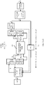
- the electrochemical cell 300 may complete charging together with a link (referred to as a first link for short below) including the port 1 shown in FIG. 3A-1 and FIG. 3A-2 and a link (referred to as a second link for short below) including the port 2 shown in FIG. 3A-1 and FIG. 3A-2 .
- a current I 0 flows in through a charging interface, and passes through a sub-board circuit and a level-1 buck circuit, to output a current I 1 .
- I 1 ⁇ I 0 .
- the current I 1 is divided into I 2 and I 3 , and I 2 is converted into a larger current I 4 through a level-2 buck circuit 1, and the current I 4 is input to the electrochemical cell 300 from the port 1 of the electrochemical cell 300 through a first battery connection circuit, to complete charging on the first link.
- the current I 3 obtained from I 1 through division flows through a mainboard circuit and a level-2 buck circuit 2 through a flexible circuit board (Flexible Printed Circuit, FPC), to output a higher current I 5 , and the current I 5 is input to the electrochemical cell 300 from the port 2 of the electrochemical cell 300 through a second battery connection circuit, to complete charging on the second link.
- FPC Flexible Printed Circuit
- the charging is completed by the electrochemical cell 300 that includes a plurality of ports shown in FIG. 3A-1 and FIG. 3A-2 , so that heat dissipation pressure of high-current charging on a single link can be reduced, charging efficiency of the battery can be improved, and the battery can have a stronger fast charging capability.
- a maximum current threshold of the single charging link is 12A.
- the charging current of the single charging link generally needs to be controlled below 12A. Because a battery of the single link is limited by the charging current, it is difficult to further improve a high-current charging capability, causing a bottleneck.
- the input currents I 4 and I 5 of the two ports are controlled to be 6A, so that 12A charging of the battery can be easily implemented, and the single charging link only needs to withstand heat generated during 6A charging. Therefore, heat dissipation pressure of the single charging link is much lower than that of a conventional battery with only one charging link.
- the battery provided in embodiments of this application may perform charging at the current 12A on two charging links, and an overall charging current of the battery may reach 24A, so that the single link only needs to withstand heat dissipation pressure during 12A charging. Therefore, the charging capability and charging efficiency are improved exponentially.
- the battery provided in embodiments of this application performs charging, if one charging link is occupied or faulty, it is further ensured that the battery can normally perform charging. For example, when the charging link including the port 2 performs discharging at a high current, the charging link including the port 1 normally performs charging.
- a dashed arrow represents a discharging current path direction. Discharging of the electrochemical cell 300 may be completed by using the first link and/or the second link. Specifically, a current I 6 flows out from the port 2 of the electrochemical cell 300, and passes through the second battery connection circuit and then arrives at the mainboard circuit. A current I 7 flows out from the port 1 of the electrochemical cell 300, and passes through the first battery connection circuit and the FPC and then arrives at the mainboard circuit, to finally output a current I 8 from the mainboard circuit to a load.
- charging and discharging of the battery may be completed by using both the first link and the second link or any one of the first link and the second link.
- the first link may be used for charging, and the second link may be for discharging.
- the second link may be used for charging, and the first link may be for discharging. This is not limited in embodiments of this application.
- FIG. 3A-1 and FIG. 3A-2 is merely a schematic diagram of charging/discharging of an electrochemical cell with four tabs.
- a specific charging/discharging circuit is not limited in embodiments of this application.
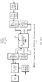
- the schematic diagram of the charging/discharging circuit of the electrochemical cell 300 with four tabs may alternatively be a schematic circuit diagram shown in (a) in FIG. 3B-1 to FIG. 3B-4 , (b) in FIG. 3B-1 to FIG. 3B-4 , (c) in FIG. 3B-1 to FIG. 3B-4 , or (d) in FIG. 3B-1 to FIG. 3B-4 .
- the tab disposing manner shown in FIG. 2A and FIG. 2B is applicable to an electrode including any quantity of tabs.
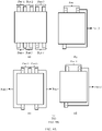
- the first side of the first electrode in embodiments of this application may alternatively be a structure that is shown in (a) in FIG. 4 and in which three first tabs are disposed in the middle, a structure that is shown in (b) in FIG.
- the first electrode shown in (a) in FIG. 4 and including three tabs includes two first tabs protruding from a first long side of the first electrode and one first tab protruding from a second long side of the first electrode.
- the first electrode shown in (b) in FIG. 4 and including four tabs includes two first tabs protruding from a first long side of the first electrode and two first tabs protruding from a second long side of the first electrode.
- the first side of the first electrode may have a structure that is shown in (c) in FIG. 4 and in which one first tab is disposed in the middle, or another similar structure.
- the tab disposing manner shown in FIG. 2A and FIG. 2B is also applicable to a second electrode including any quantity of tabs, as shown in (a) in FIG.
- the first side of the second electrode may be a structure shown in (c) in FIG. 5 or another similar structure.
- the multi-tab electrochemical cell may further include the first electrode shown in any one of (a1) in FIG. 2A and FIG. 2B and (a2) in FIG. 2A and FIG. 2B , (a) in FIG. 4 , (b) in FIG. 4 , and (d) in FIG. 4 , and the second electrode shown in (a) in FIG. 5 , (b) in FIG. 5 , (c) in FIG. 5 , or (d) in FIG. 5 .
- the multi-tab electrochemical cell may further include the first electrode shown in (c) in FIG. 4 , and the second electrode shown in (a) in FIG. 5 , (b) in FIG. 5 , or (d) in FIG. 5 .
- the second electrode includes a plurality of non-edge second blank areas (that is, j 1 > 1), and the n second tabs are dispersedly disposed on the plurality of non-edge second blank areas.
- m ⁇ 1, and n 1.
- the first electrode includes a plurality of non-edge first blank areas (that is, i 1 > 1), and the m first tabs are dispersedly disposed on the plurality of non-edge first blank areas.
- the first electrode may have the structure shown in any one of (a1) in FIG. 2A and FIG. 2B and (a2) in FIG. 2A and FIG. 2B , (a) in FIG. 4 , (b) in FIG. 4 , and (c) in FIG. 4 , or another structure similar to a structure in which a tab is disposed in the middle.
- the second electrode may have a structure shown in (a) in FIG. 6 .
- the second electrode includes six second tabs disposed on three non-edge second blank areas. One second electrode protruding from a first long side of the second electrode and one second tab protruding from a second long side of the second electrode are disposed on each non-edge second blank area.
- the second electrode may have a structure shown in (b) in FIG. 6 .
- the second electrode includes four second tabs disposed on two non-edge second blank areas. One second tab protruding from a first long side of the second electrode and one second tab protruding from a second long side of the second electrode are disposed on each non-edge second blank area.
- the second electrode may have a structure shown in (c) in FIG. 6 . As shown in (c) in FIG. 6 , the second electrode includes three second tabs disposed on two non-edge second blank areas.
- the second electrode may have another structure similar to a structure in which a plurality of tabs are disposed in the middle of a plurality of non-edge second blank areas.
- the second electrode may have the structure shown in any one of (b1) in FIG. 2A and FIG. 2B and (b2) in FIG. 2A and FIG. 2B , (a) in FIG. 5 , (b) in FIG. 5 , (c) in FIG. 5 , and (d) in FIG. 5 , or another structure similar to a structure in which a tab is disposed in the middle of one non-edge second blank area.
- the first electrode may have a structure shown in (a) in FIG. 7 . As shown in (a) in FIG. 7 , the first electrode includes six first tabs disposed on three non-edge first blank areas.
- the first electrode may have a structure shown in (b) in FIG. 7 .
- the first electrode includes four first tabs disposed on two non-edge first blank areas.
- One first tab protruding from a first long side of the first electrode and one first tab protruding from a second long side of the first electrode are disposed on each non-edge first blank area.
- the first electrode may have a structure shown in (c) in FIG. 7 . As shown in (c) in FIG.
- the first electrode includes three first tabs disposed on two non-edge first blank areas.
- One first tab protruding from a first long side of the first electrode and one first tab protruding from a second long side of the first electrode are disposed on one non-edge first blank area, and one first tab protruding from the second long side of the first electrode is disposed on one non-edge first blank area.
- the first electrode may have another structure similar to a structure in which a plurality of tabs are disposed in the middle of a plurality of non-edge first blank areas.
- the first electrode includes a plurality of non-edge first blank areas (that is, i 1 > 1), and the m first tabs are dispersedly disposed on the plurality of non-edge first blank areas.
- the second electrode includes a plurality of non-edge second blank areas (that is, j 1 > 1), and the n second tabs are dispersedly disposed on the plurality of non-edge second blank areas.
- the first electrode may have the structure shown in any one of (a) in FIG. 7 , (b) in FIG. 7 , and (c) in FIG. 7 , or another structure similar to a structure in which a plurality of tabs are disposed in the middle of a plurality of non-edge first blank areas.
- the second electrode may have the structure shown in any one of (a) in FIG. 6 , (b) in FIG. 6 , and (c) in FIG. 6 , or another structure similar to a structure in which a plurality of tabs are disposed in the middle of a plurality of non-edge second blank areas.
- An electrochemical cell with eight tabs that includes the first electrode including four tabs and shown in (b) in FIG. 7 and the second electrode including four tabs and shown in (b) in FIG. 6 may have four charging/discharging ports (including a port 1, a port 2, a port 3, and a port 4) shown in (a) in FIG. 8A and FIG. 8B .
- a charging/discharging circuit of the electrochemical cell may be shown in (b) in FIG. 8A and FIG. 8B .
- the electrochemical cell including eight tabs and shown in (a) in FIG. 8A and FIG. 8B may be completed by using at least one of a first link, a second link, a third link, and a fourth link.
- the first link, the second link, the third link, and the fourth link may be jointly used to complete charging, or may be separately used to complete charging and discharging.
- the first link is charging interface ⁇ sub-board circuit+level-1 buck circuit ⁇ level-2 buck circuit ⁇ first battery connection circuit+first protection circuit ⁇ port 1.
- the second link is charging interface ⁇ sub-board circuit+level-1 buck circuit ⁇ level-2 buck circuit ⁇ second battery connection circuit+second protection circuit ⁇ port 2.
- the third link is charging interface ⁇ sub-board circuit+level-1 buck circuit ⁇ FPC ⁇ mainboard circuit+level-2 buck circuit 2 ⁇ third battery connection circuit+third protection circuit ⁇ port 3.
- the fourth link is charging interface ⁇ sub-board circuit+level-1 buck circuit ⁇ FPC ⁇ mainboard circuit+level-2 buck circuit 2 ⁇ fourth battery connection circuit+fourth protection circuit ⁇ port 4.
- the battery that includes the electrochemical cell including eight tabs and shown in (a) in FIG. 8A and FIG. 8B is used to complete charging, so that fast charging and high-power charging capabilities of the battery can be further improved.
- an electrochemical cell with 10 tabs that includes the first electrode including four tabs and shown in (b) in FIG. 7 and the second electrode including six tabs and shown in (a) in FIG. 6 may have six charging/discharging ports shown in (a) in FIG. 9A and FIG. 9B .
- Five groups of tabs including the four first tabs of the first electrode and the six second tabs of the second electrode may form six charging/discharging ports. Therefore, fast charging and high-power charging capabilities of the battery can be further improved.
- one first tab may be multiplexed for two second tabs, to form more charging/discharging ports for charging.
- charging/discharging ports may also be formed in a multiplexing manner similar to that of the electrochemical cell that includes the first electrode including four tabs and shown in (b) in FIG. 7 and the second electrode including six tabs and shown in (a) in FIG. 6 .
- Case (2) At least one of the m first tabs is disposed on the edge, and the n second tabs are all disposed in the middle.
- the at least one first blank area on the first electrode includes one edge first blank area, and at least one of the m first tabs is disposed on the edge first blank area.
- the at least one second blank area on the second electrode includes j 2 non-edge second blank areas, and the n second tabs are disposed on the j 2 non-edge second blank areas.
- j 2 is a positive integer.
- the first electrode includes only one first blank area, the first blank area is an edge first blank area, and the m first tabs are all disposed on the edge first blank area.
- the at least one second blank area on the second electrode includes j 2 edge second blank areas, and the n second tabs are disposed on the j 2 non-edge second blank areas.
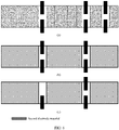
- the first electrode may have a structure that is shown in (a) in FIG. 10 and in which two tabs are disposed on the edge
- the second electrode may have the structure that is shown in (b1) in FIG. 2A and FIG. 2B and (b2) in FIG. 2A and FIG. 2B and in which two tabs are disposed in the middle
- a charging/discharging port of an included electrochemical cell with four tabs may be shown in (a) in FIG. 3A-1 and FIG. 3A-2
- a charging/discharging circuit of a battery including the electrochemical cell with four tabs may be any of the charging/discharging circuits shown in (b) in FIG. 3A-1 and FIG. 3A-2 , (a) in FIG. 3B-1 to FIG. 3B-4 , (b) in FIG. 3B-1 to FIG. 3B-4 , (c) in FIG. 3B-1 to FIG. 3B-4 , and (d) in FIG. 3B-1 to FIG. 3B-4 .
- the first electrode may have a structure that is shown in (a) in FIG. 10 and in which two tabs are disposed on the edge
- the second electrode may have the structure that is shown in (c) in FIG. 5 and in which one tab is disposed in the middle.
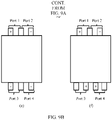
- a charging/discharging port of an included electrochemical cell with three tabs may be shown in (b) in FIG. 9A and FIG. 9B
- one second tab in the second electrode shown in (c) in FIG. 5 is multiplexed for two first tabs in the first electrode shown in (a) in FIG. 10
- a charging/discharging circuit of a battery including the electrochemical cell with three tabs may be any of the charging/discharging circuits shown in (b) in FIG. 3A-1 and FIG.
- FIG. 3A-2 (a) in FIG. 3B-1 to FIG. 3B-4 , (b) in FIG. 3B-1 to FIG. 3B-4 , (c) in FIG. 3B-1 to FIG. 3B-4 , and (d) in FIG. 3B-1 to FIG. 3B-4 .
- the first electrode may have a structure that is shown in (a) in FIG. 10 and in which two tabs are disposed on the edge
- the second electrode may have the structure that is shown in (b) in FIG. 5 or (c) in FIG. 6 and in which three tabs are disposed in the middle.
- a charging/discharging port of an included electrochemical cell with five tabs may be shown in (c) in FIG. 9A and FIG. 9B
- two first tabs in the first electrode shown in (a) in FIG. 10 are multiplexed for three second tabs in the second electrode shown in (b) in FIG. 5 or (c) in FIG. 6 .
- a charging/discharging circuit of a battery including the electrochemical cell with five tabs may be any of the charging/discharging circuits shown in (b) in FIG. 3A-1 and FIG. 3A-2 , (a) in FIG. 3B-1 to FIG. 3B-4 , (b) in FIG. 3B-1 to FIG. 3B-4 , (c) in FIG. 3B-1 to FIG. 3B-4 , and (d) in FIG. 3B-1 to FIG. 3B-4 .
- the first electrode may have a structure that is shown in (b) in FIG. 10 and in which one tab is disposed on the edge
- the second electrode may have the structure that is shown in (b1) in FIG. 2A and FIG. 2B and (b2) in FIG. 2A and FIG. 2B and in which two tabs are disposed in the middle
- a charging/discharging port of an included electrochemical cell with three tabs may be shown in (d) in FIG. 9A and FIG. 9B
- one first tab in the first electrode shown in (b) in FIG. 10 is multiplexed for two second tabs in the second electrode shown in (b1) in FIG. 2A and FIG. 2B or (b2) in FIG. 2A and FIG. 2B .
- a charging/discharging circuit of a battery including the electrochemical cell with three tabs may be any of the charging/discharging circuits shown in (b) in FIG. 3A-1 and FIG.3A-2 , (a) in FIG. 3B-1 to FIG. 3B-4 , (b) in FIG. 3B-1 to FIG. 3B-4 , (c) in FIG. 3B-1 to FIG. 3B-4 , and (d) in FIG. 3B-1 to FIG. 3B-4 .
- the first electrode may have a structure that is shown in (c) in FIG. 10 and in which three tabs are disposed on the edge, or another similar structure in which a tab is disposed on the edge.
- the second electrode may have any one of the structure that is shown in (b1) in FIG. 2A and FIG. 2B and (b2) in FIG. 2A and FIG. 2B and in which two tabs are disposed in the middle, the structure that is shown in (a) in FIG. 5 and in which four tabs are disposed in the middle, the structure that is shown in (b) in FIG. 5 and in which three tabs are disposed in the middle, the structure that is shown in (c) in FIG.
- An electrochemical cell including six tabs and shown in (e) in FIG. 9A and FIG. 9B may include the first electrode that is shown in (c) in FIG. 10 and that has the structure in which three tabs are disposed on the edge, and the second electrode that is shown in (b) in FIG. 5 and that has the structure in which three tabs are disposed in the middle.
- the first electrode includes at least one edge first blank area and at least one non-edge first blank area, at least one of the m first tabs is disposed on the at least one edge first blank area, and at least one of the m first tabs is disposed on the at least one non-edge first blank area.
- the at least one second blank area on the second electrode includes j 2 non-edge second blank areas, and the n second tabs are disposed on the j 2 non-edge second blank areas.
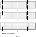
- the first electrode may have a structure that is shown in (a) in FIG. 11 and in which two tabs are disposed in the middle and two tabs are disposed on the edge
- the second electrode may have the structure that is shown in (a) in FIG. 5 and in which four tabs are disposed in the middle.
- a charging/discharging port of an included electrochemical cell with eight tabs may be shown in (a) in FIG. 8A and FIG. 8B .
- a charging/discharging circuit of a battery including the electrochemical cell with eight tabs may be shown in (b) in FIG. 8A and FIG. 8B .
- the first electrode may have a structure that is shown in (a) in FIG. 11 and in which two tabs are disposed in the middle and two tabs are disposed on the edge
- the second electrode may have any one of the structure that is shown in (b1) in FIG. 2A and FIG. 2B and (b2) in FIG. 2A and FIG. 2B and in which two tabs are disposed in the middle, the structure that is shown in (b) in FIG. 5 and in which three tabs are disposed in the middle, the structure that is shown in (d) in FIG. 5 and in which two tabs are disposed in the middle, the structure that is shown in (a) in FIG. 6 and in which six tabs are disposed in the middle, the structure that is shown in (b) in FIG.
- the first electrode may have a structure that is shown in (b) in FIG. 11 and in which two tabs are disposed in the middle and one tab is disposed on the edge
- the second electrode may have the structure that is shown in (b) in FIG. 6 and in which four tabs are disposed in the middle.
- the first electrode may have a structure that is shown in (b) in FIG. 11 and in which two tabs are disposed in the middle and one tab is disposed on the edge, or another similar structure in which a tab is disposed in the middle and a tab is disposed on the edge.
- the second electrode may have any one of the structure that is shown in (b1) in FIG. 2A and FIG. 2B and (b2) in FIG. 2A and FIG. 2B and in which two tabs are disposed in the middle, the structure that is shown in (a) in FIG. 5 and in which four tabs are disposed in the middle, the structure that is shown in (b) in FIG. 5 and in which three tabs are disposed in the middle, the structure that is shown in (d) in FIG.
- the first electrode may have a structure that is shown in (c) in FIG. 11 and in which one tab is disposed in the middle and one tab is disposed on the edge, or another similar structure in which a tab is disposed in the middle and a tab is disposed on the edge.
- the second electrode may have any one of the structure that is shown in (b1) in FIG. 2A and FIG. 2B or (b2) in FIG. 2A and FIG. 2B and in which two tabs are disposed in the middle, the structure that is shown in (a) in FIG. 5 and in which four tabs are disposed in the middle, the structure that is shown in (b) in FIG. 5 and in which three tabs are disposed in the middle, the structure that is shown in (d) in FIG.
- Case (3) The m first tabs are all disposed in the middle, and at least one of the n second tabs is disposed on the edge.
- the at least one first blank area on the first electrode includes i 2 non-edge first blank areas, and the m first tabs are disposed on the i 2 non-edge first blank areas.
- the at least one second blank area on the second electrode includes one edge second blank area, and at least one of the n second tabs is disposed on the edge second blank area.
- the second electrode includes only one second blank area, the second blank area is an edge second blank area, and the n second tabs are all disposed on the edge second blank area.
- the at least one first blank area on the first electrode includes i 2 non-edge first blank areas, and the m first tabs are disposed on the i 2 non-edge first blank areas.
- the second electrode may have a structure that is shown in (a) in FIG. 12 and in which two tabs are disposed on the edge
- the first electrode may have the structure that is shown in (a1) in FIG. 2A and FIG. 2B and (a2) in FIG. 2A and FIG. 2B and in which two tabs are disposed in the middle
- a charging/discharging port of an included electrochemical cell with four tabs may be shown in (a) in FIG. 3A-1 and FIG. 3A-2
- a charging/discharging circuit including the electrochemical cell with four tabs may be any of the charging/discharging circuits shown in (b) in FIG. 3A-1 and FIG. 3A-2 , (a) in FIG. 3B-1 to FIG. 3B-4 , (b) in FIG. 3B-1 to FIG. 3B-4 , (c) in FIG. 3B-1 to FIG. 3B-4 , and (d) in FIG. 3B-1 to FIG. 3B-4 .
- the second electrode may have a structure that is shown in (a) in FIG. 12 and in which two tabs are disposed on the edge
- the first electrode may have any one of the structure that is shown in (a) in FIG. 4 or (c) in FIG. 7 and in which three tabs are disposed in the middle, the structure that is shown in (b) in FIG. 4 or (b) in FIG. 7 and in which four tabs are disposed in the middle, the structure that is shown in (c) in FIG. 4 and in which one tab is disposed in the middle, and the structure that is shown in (d) in FIG. 4 and in which two tabs are disposed in the middle, or another similar structure.
- a diagram of the included charging/discharging port and a diagram of the included charging/discharging link refer to the foregoing examples.
- the second electrode may have a structure that is shown in (b) in FIG. 12 and in which one tab is disposed on the edge, or another similar structure in which a tab is disposed on the edge.
- the first electrode may have any one of the structure that is shown in (a1) in FIG. 2A and FIG. 2B and (a2) in FIG. 2A and FIG. 2B , or (d) in FIG. 4 and in which two tabs are disposed in the middle, the structure that is shown in (a) in FIG. 4 or (c) in FIG. 7 and in which three tabs are disposed in the middle, and the structure that is shown in (b) in FIG. 4 or (b) in FIG.
- the second electrode may have a structure that is shown in (c) in FIG. 12 and in which three tabs are disposed on the edge, or another similar structure in which a tab is disposed on the edge.
- the first electrode may have any one of the structure that is shown in (a1) in FIG. 2A and FIG. 2B and (a2) in FIG. 2A and FIG. 2B , or (d) in FIG. 4 and in which two tabs are disposed in the middle, the structure that is shown in (a) in FIG. 4 or (c) in FIG. 7 and in which three tabs are disposed in the middle, the structure that is shown in (b) in FIG. 4 or (b) in FIG.
- the second electrode includes at least one edge second blank area and at least one non-edge second blank area, at least one of the n second tabs is disposed on the at least one edge second blank area, and at least one of the n second tabs is disposed on the at least one non-edge second blank area.
- the at least one first blank area on the first electrode includes i 2 non-edge first blank areas, and the m first tabs are disposed on the i 2 non-edge first blank areas.
- the second electrode may have a structure that is shown in (a) in FIG. 13 and in which two tabs are disposed in the middle and two tabs are disposed on the edge
- the first electrode may have the structure that is shown in (a) in FIG. 4 and in which three tabs are disposed in the middle.
- a charging/discharging port of an included electrochemical cell with seven tabs may be shown in (f) in FIG. 9A and FIG. 9B .
- a charging/discharging circuit including the electrochemical cell with seven tabs may be shown in (b) in FIG. 8A and FIG. 8B .
- the second electrode may have a structure that is shown in (a) in FIG. 13 and in which two tabs are disposed in the middle and two tabs are disposed on the edge
- the first electrode may have any one of the structure that is shown in (b) in FIG. 4 or (b) in FIG. 7 and in which four tabs are disposed in the middle, the structure that is shown in (c) in FIG. 4 and in which two tabs are disposed in the middle, the structure that is shown in (a) in FIG. 7 and in which six tabs are disposed in the middle, and the structure that is shown in (c) in FIG. 7 and in which three tabs are disposed in the middle, or another similar structure in which a tab is disposed in the middle.
- a diagram of the included charging/discharging port and a diagram of the included charging/discharging link refer to the foregoing examples.
- the second electrode may have a structure that is shown in (b) in FIG. 13 and in which two tabs are disposed in the middle and one tab is disposed on the edge, a structure that is shown in (c) in FIG. 13 and in which one tab is disposed in the middle and two tabs are disposed on the edge, or another similar structure in which a tab is disposed in the middle and a tab is disposed on the edge.
- the first electrode may have any one of the structure that is shown in (a1) in FIG. 2A and FIG. 2B and (a2) in FIG. 2A and FIG. 2B , or (d) in FIG. 4 and in which two tabs are disposed in the middle, the structure that is shown in (a) in FIG. 4 or (c) in FIG.
- an embodiment of this application further provides a battery including a jelly roll obtained by winding a first electrode with a tab disposed on the edge and a second electrode with a tab disposed on the edge.
- the first electrode includes at least one edge first blank area, and the m first tabs are disposed on the at least one edge first blank area.
- the second electrode includes at least one edge second blank area, and the n second tabs are disposed on the at least one edge second blank area.
- m and n are positive integers, m ⁇ 1, n ⁇ 1, and m and n are not equal to 1 at the same time.
- the first electrode may have a structure that is shown in (a) in FIG. 10 and in which two tabs are disposed on the edge, a structure that is shown in (c) in FIG. 10 and in which three tabs are disposed on the edge, or another similar structure in which a tab is disposed on the edge.
- the second electrode may have a structure that is shown in (a) in FIG. 12 and in which two tabs are disposed on the edge, a structure that is shown in (b) in FIG. 12 and in which one tab is disposed on the edge, a structure that is shown in (c) in FIG. 12 and in which three tabs are disposed on the edge, or another similar structure in which a tab is disposed on the edge.
- the first electrode may have a structure that is shown in (b) in FIG. 10 and in which one tab is disposed on the edge, a structure that is shown in (a) in FIG. 12 and in which two tabs are disposed on the edge, a structure that is shown in (c) in FIG. 12 and in which three tabs are disposed on the edge, or another similar structure in which a tab is disposed on the edge.
- the battery that includes the jelly roll obtained by winding the first electrode with a tab disposed on the edge and the second electrode with a tab disposed on the edge includes at least three tabs.
- the at least three tabs may form at least two ports for charging and/or discharging, to reduce heat dissipation pressure of high-current charging on a single link, improve charging efficiency of the battery, and support a stronger fast charging capability of the battery.
- the first electrode may be understood as an electrode with two tabs that includes a first tab 1401-1 and a first tab 1401-2.
- a second tab and each of the first tab 1401-1 and the first tab 1401-2 may form a charging/discharging port.
- a separation layer may be further disposed on a first bending area of the first electrode.
- the separation layer is used to reduce a risk of lithium plating and shading generated by an inner-ring electrode.
- the first bending area of the first electrode is a position close to a center of the jelly roll that is bent first when the first electrode and the second electrode are wound. As shown in (b) in FIG. 15 , 1502 shows the first bending area of the first electrode.
- the separation layer may be PET tape, and the PET tape may be disposed on the first bending area of the first electrode in a pasting manner.
- PET tape 1502 is disposed on the first electrode.
- the PET tape 1502 pasted on a first bending area 1501 of the first electrode can effectively reduce a risk of lithium plating and shading that may be generated by an inner-ring electrode.
- an embodiment of this application further provides an electrode winding method.
- An occasion at which the second electrode is inserted into the first electrode may be determined based on specific structures of the first electrode and the second electrode provided in embodiments of this application.
- FIG. 16 is a schematic diagram of an electrode winding process by using an example in which the jelly roll shown in (c) in FIG. 2A and FIG. 2B is obtained by winding the first electrode shown in (a1) in FIG. 2A and FIG. 2B and (a2) in FIG. 2A and FIG. 2B and the second electrode shown in (b1) in FIG. 2A and FIG. 2B and (b2) in FIG. 2A and FIG. 2B .
- the electrode winding process may mainly include the following steps: S1: Bend the second electrode, the first separator 207-1, and the second separator 207-2 for the first time by using a winding core 1601, to form a first bending area 1602 of the second electrode.
- FIG. 16 merely shows the electrode winding method by using the jelly roll shown in (c) in FIG. 2A and FIG. 2B as an example.
- a method for winding a first electrode and a second electrode of another structure refer to the winding method shown in FIG. 16 . Details are not described in embodiments of this application.
- an embodiment of this application further provides a terminal device.
- the terminal device includes a multi-tab battery of any one of the foregoing possible structures in embodiments of this application.
- the terminal device further includes at least two connection circuits, at least two protection circuits, and at least two buck circuits.
- the terminal device may be a desktop device, a laptop device, a handheld device, a wearable device, a smart home device, a computing device, or a vehicle-mounted device.
- the terminal device may be a netbook, a tablet computer, a smart watch, an ultra-mobile personal computer (ultra-mobile personal computer, UMPC), a smart camera, a netbook, a personal digital assistant (personal digital assistant, PDA), a portable multimedia player (portable multimedia player, PMP), an AR (augmented reality)/VR (virtual reality) device, a wireless device on aircrafts, a wireless device on robots, a wireless device in industrial control, a wireless device in telemedicine, a wireless device in smart grid, a wireless device in smart city (smart city), or a wireless device in smart home (smart home).
- the user equipment may be a wireless device or the like in a narrowband (narrowband, NB) technology.
- the terminal device includes a communications interface, a processor, a memory, and at least two battery connectors.
- the communications interface also functions as a charging interface.
- the at least two battery connectors are connected to a multi-tab battery.
- the multi-tab battery includes at least two groups of ports respectively connected to the at least two battery connectors, and each group of ports includes a first tab and a second tab.
- the multi-tab battery obtains a direct current from a power adapter through the communications interface of the terminal device, and performs charging. Specifically, when detecting that the power adapter is electrically connected to the terminal device, the terminal device completes charging by using any one or more of the at least two groups of ports.
- the terminal device When detecting that a load of the terminal device has a power supply requirement, the terminal device supplies power to the load by using any one or more of the at least two groups of ports.
- the load of the terminal device may be a touchscreen, a speaker, a vibration motor, or the like.
- FIG. 17 describes a hardware structure of a terminal device by using a mobile phone as an example.
- the mobile phone includes a mainboard 1710, an interface sub-board 1720, a multi-tab battery 1730, and a communications interface 1740.
- the communications interface is located on the interface sub-board 1720.
- a first battery connector 1750 connected to a first port of the multi-tab battery is disposed on the mainboard.
- a second battery connector 1740 connected to a second port of the multi-tab battery is disposed on the interface sub-board 1720.
- the mobile phone When the mobile phone detects that the load of the mobile phone has a power supply requirement, the mobile phone completes discharging of the multi-tab battery.
- the mobile phone may complete charging or discharging through both the first port and the second port, or may separately complete charging and discharging through the first port and the second port, or may complete charging and discharging in another manner. This is not limited in embodiments of this application.
- the mobile phone may further include a camera (a front-facing camera and/or a rear-facing camera), a flash, a micro projection apparatus, a near field communication (NFC) apparatus, a sensor, a radio frequency module, an antenna, and the like that are not shown in FIG. 17 . Details are not described herein.
- the mobile phone including the multi-tab battery that has the two ports is merely used as an example in FIG. 17 .
- a specific structure of the terminal device is not limited in embodiments of this application.
- the terminal device may further include another hardware module that has an interaction relationship with the hardware module shown in FIG. 17 . This is not specifically limited herein.
Landscapes
- Chemical & Material Sciences (AREA)
- Chemical Kinetics & Catalysis (AREA)
- Electrochemistry (AREA)
- General Chemical & Material Sciences (AREA)
- Engineering & Computer Science (AREA)
- Manufacturing & Machinery (AREA)
- Materials Engineering (AREA)
- Connection Of Batteries Or Terminals (AREA)
Abstract
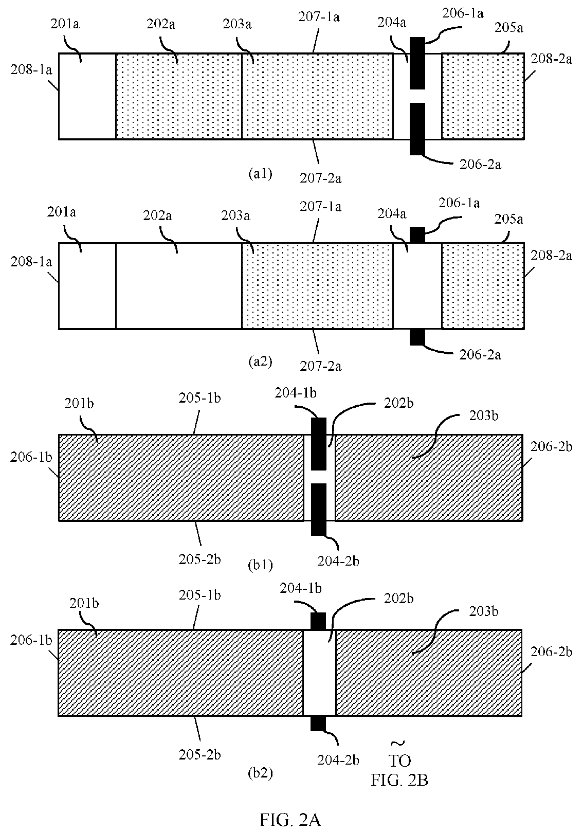
Description
- This application claims priority to
Chinese Patent Application No. 201911359846.3, filed with the China National Intellectual Property Administration on December 25, 2019 - Embodiments of this application relate to the field of terminal device battery technologies, and in particular, to a battery and a terminal device.
- As functions of a terminal device (for example, a mobile phone or a tablet) become more powerful, power consumption of the terminal device is significantly increased, and consequently a battery of the terminal drains increasingly sooner. However, a conventional battery is charged slowly, and consequently user experience is seriously affected.
- A battery including an electrochemical cell shown in (d) in
FIG. 1A andFIG. 1B is used as an example. (c) inFIG. 1A andFIG. 1B is a sectional view of an inner-ring jelly roll of the electrochemical cell shown in (d) inFIG. 1A andFIG. 1B . The jelly roll corresponding to (c) inFIG. 1A andFIG. 1B is obtained by winding a first electrode shown in (a) inFIG. 1A andFIG. 1B and a second electrode shown in (b) inFIG. 1A andFIG. 1B . - A charging speed of the conventional battery shown in (d) in
FIG. 1A andFIG. 1B is difficult to continuously increase because of the following two factors: 1. A tab is usually disposed on the right edge of the electrode (as shown in (a) inFIG. 1A andFIG. 1B and (b) inFIG. 1A andFIG. 1B ). Consequently, charging current transmission efficiency is low, and the charging speed is slow. 2. The conventional battery has only one first tab (for example, an anode tab) and only one second tab (for example, a cathode tab), and consequently only one charging link can be provided. A capability of one charging link to withstand a large current is limited, and consequently a charging current of the battery cannot be continuously increased. The foregoing two factors cause a bottleneck, where the charging speed of the conventional battery is difficult to continuously increase. - This application provides a battery and a terminal device, to increase a fast charging capability, and relieve heat dissipation pressure of a charging/discharging link.
- To achieve the foregoing objectives, the following technical solutions are used in embodiments of this application.
- According to a first aspect, a battery is provided. The battery includes a multi-tab electrochemical cell, and the multi-tab electrochemical cell is obtained by winding a first electrode, a second electrode, and a separator used to separate the first electrode from the second electrode. The first electrode includes at least one first blank area, and m first tabs are disposed on the at least one first blank area; the second electrode includes at least one second blank area, and n second tabs are disposed on the at least one second blank area; and m and n are positive integers, m ≥ 1, n ≥ 1, and m and n are not equal to 1 at the same time. The at least one first blank area and the at least one second blank area each include at least one non-edge blank area. At least two tabs are disposed on at least one of the at least one first blank area and the at least one second blank area, at least one of the at least two tabs protrudes from a first side of a corresponding electrode, and at least one of the at least two tabs protrudes from a second side of the corresponding electrode; and the first side is a first long side of the corresponding electrode, and the second side is a second long side of the corresponding electrode. The blank area is an area in which a current collector is not coated with an electrode material.
- According to the technical solution provided in the first aspect, the battery having at least two ports is obtained by winding a first electrode and a second electrode that have a novel structure (for example, a plurality of tabs separately protrude from a first long side and a second long side of an electrode, and the tabs are disposed on a non-edge area). The battery and another charging/discharging component may form at least two charging/discharging links, to increase a fast charging capability, and relieve heat dissipation pressure of each charging/discharging link. Moreover, stress inside the battery is evenly distributed, so that interface deterioration of the electrode that is caused by stress unevenness can be alleviated. This effectively reduces a risk of shading and lithium plating generated in a cathode charging/discharging cycle, and improves performance of the battery.
- With reference to the first aspect, in a first possible implementation, the at least one first blank area includes i1 non-edge first blank areas, and the m first tabs are disposed on the i1 non-edge first blank areas; the at least one second blank area includes j1 non-edge second blank areas, and the n second tabs are disposed on the j1 non-edge second blank areas; and i 1 and
j 1 are positive integers. The battery having at least two ports is obtained by winding a first electrode on which a plurality of tabs are disposed in the middle and separately protrude from a first long side and a second long side of an electrode, and a second electrode on which a plurality of tabs are disposed in the middle and separately protrude from a first long side and a second long side of an electrode. The battery and another charging/discharging component may form at least two charging/discharging links, to increase a fast charging capability, and relieve heat dissipation pressure of each charging/discharging link. Moreover, stress inside the battery is evenly distributed, so that interface deterioration of the electrode that is caused by stress unevenness can be alleviated. This effectively reduces a risk of shading and lithium plating generated in a cathode charging/discharging cycle, and improves performance of the battery. - With reference to the first aspect, in a second possible implementation, the at least one first blank area includes i2 non-edge first blank areas, the m first tabs are disposed on the i2 non-edge first blank areas, and i2 is a positive integer. The at least one second blank area includes one edge second blank area, and at least one of the n second tabs is disposed on the edge second blank area. The battery having at least two ports is obtained by winding a first electrode on which a plurality of tabs are disposed in the middle and separately protrude from a first long side and a second long side of an electrode, and a second electrode on which at least one tab is disposed on the edge. The battery and another charging/discharging component may form at least two charging/discharging links, to increase a fast charging capability, and relieve heat dissipation pressure of each charging/discharging link. Moreover, stress inside the battery is evenly distributed, so that interface deterioration of the electrode that is caused by stress unevenness can be alleviated. This effectively reduces a risk of shading and lithium plating generated in a cathode charging/discharging cycle, and improves performance of the battery.
- With reference to the first aspect, in a third possible implementation, the at least one first blank area includes one edge first blank area, and at least one of the m first tabs is disposed on the edge first blank area. The at least one second blank area includes j2 non-edge second blank areas, the n second tabs are disposed on the j2 non-edge second blank areas, and j2 is a positive integer. The battery having at least two ports is obtained by winding a first electrode on which at least one tab is disposed on the edge, and a second electrode on which a plurality of tabs are disposed in the middle and separately protrude from a first long side and a second long side of an electrode. The battery and another charging/discharging component may form at least two charging/discharging links, to increase a fast charging capability, and relieve heat dissipation pressure of each charging/discharging link. Moreover, stress inside the battery is evenly distributed, so that interface deterioration of the electrode that is caused by stress unevenness can be alleviated. This effectively reduces a risk of shading and lithium plating generated in a cathode charging/discharging cycle, and improves performance of the battery.
- With reference to any one of the first aspect, or the first to the third possible implementations of the first aspect, in a fourth possible implementation, the non-edge blank area is disposed between double-sided areas, or between a double-sided area and a single-sided area, or between single-sided areas. The edge blank area is disposed next to a first short side of the electrode or a second short side of the electrode. The single-sided area is an area in which one side of the current collector is coated with the electrode material, and the double-sided area is an area in which both sides of the current collector are coated with the electrode material.
- With reference to any one of the first aspect, or the first to the fourth possible implementations of the first aspect, in a fifth possible implementation, the first electrode is an anode electrode, and the second electrode is a cathode electrode.
- With reference to any one of the first aspect, the first possible implementation of the first aspect, or the third to the fifth possible implementations of the first aspect, in a sixth possible implementation, the second electrode includes no edge second blank area or single-sided area.
- With reference to any one of the first aspect, or the first to the sixth possible implementations of the first aspect, in a seventh possible implementation, a separation layer is disposed inside a first bending area of the first electrode, the separation layer is used to prevent lithium plating, and the first bending area of the first electrode is a position close to a center of the battery that is bent first when the first electrode and the second electrode are wound. The separation layer is disposed inside the first bending area, so that a risk of shading and lithium plating generated in a cathode charging/discharging cycle can be effectively reduced, and performance of the battery can be improved.
- With reference to the seventh possible implementation of the first aspect, in an eighth possible implementation, the separation layer is PET tape. The PET tape is disposed inside the first bending area, so that a risk of shading and lithium plating generated in a cathode charging/discharging cycle can be effectively reduced, and performance of the battery can be improved.
- According to a second aspect, an electrode winding method is provided. The method includes: bending a second electrode and a separator for the first time to form a first bending area of the second electrode (S1); inserting a first electrode into the first bending area of the second electrode (S2); and the second electrode, the first electrode, and the separator (S3). The first electrode includes at least one first blank area, and m first tabs are disposed on the at least one first blank area; the first electrode includes at least one second blank area, and n second tabs are disposed on the at least one second blank area; and m and n are positive integers, m ≥ 1, n ≥ 1, and m and n are not equal to 1 at the same time. The at least one first blank area and the at least one second blank area each include at least one non-edge blank area. At least two tabs are disposed on at least one of the at least one first blank area and the at least one second blank area, at least one of the at least two tabs protrudes from a first side of a corresponding electrode, and at least one of the at least two tabs protrudes from a second side of the corresponding electrode; and the first side is a first long side of the corresponding electrode, and the second side is a second long side of the corresponding electrode. The blank area is an area in which a current collector is not coated with an electrode material.
- According to the technical solution provided in the second aspect, the battery having at least two charging/discharging links is obtained by winding a first electrode and a second electrode that have a novel structure (for example, a plurality of tabs separately protrude from a first long side and a second long side of an electrode, and the tabs are disposed on a non-edge area) in a special winding manner. Therefore, the battery can have a stronger fast charging capability, and heat dissipation pressure of each charging/discharging link can be relieved. Moreover, stress inside the battery is evenly distributed, so that interface deterioration of the electrode that is caused by stress unevenness can be alleviated. This effectively reduces a risk of shading and lithium plating generated in a cathode charging/discharging cycle, and improves performance of the battery.
- In a possible implementation, the first electrode and the second electrode have the structure of the first electrode or the second electrode in any one of the first to the eighth possible implementations of the first aspect.
- According to a third aspect, a terminal device is provided. The terminal device includes the battery having the structure in any one of the first aspect or the first to the eighth possible implementations of the first aspect.
- According to the technical solution provided in the third aspect, in the terminal device including the battery that has at least two ports and that is obtained by winding a first electrode and a second electrode that have a novel structure (for example, a plurality of tabs separately protrude from a first long side and a second long side of an electrode, and the tabs are disposed on a non-edge area), the battery and another charging/discharging component may form at least two charging/discharging links, so that the terminal device can have a stronger fast charging capability, and heat dissipation pressure of each charging/discharging link can be relieved. Moreover, stress inside the battery is evenly distributed, so that interface deterioration of the electrode that is caused by stress unevenness can be alleviated. This effectively reduces a risk of shading and lithium plating generated in a cathode charging/discharging cycle, improves performance of the battery, and improves user experience.
- In a possible implementation, the battery includes at least two ports, and each port includes at least one first tab and at least one second tab. A plurality of tabs of a multi-tab battery may form at least two ports, so that the battery and another charging/discharging component can form at least two charging/discharging links for charging/discharging. This improves a fast charging capability of the terminal device.
- In a possible implementation, the terminal device includes at least two charging/discharging links. The at least two charging/discharging links of the battery are used for charging/discharging, so that a fast charging capability of the terminal device can be improved.
- In a possible implementation, each charging/discharging link includes at least one port, one battery protection circuit, and one battery connection circuit. The battery protection circuit is configured to protect the battery to prevent overcharging and over-discharging. The battery connection circuit is configured to connect the battery to another component inside the terminal device, for example, connect the battery to a mainboard or a sub-board.
- In a possible implementation, at least one of the at least two charging/discharging links further includes one buck circuit. The buck circuit is configured to perform voltage conversion, to reduce energy loss and improve energy utilization.
-
-
FIG. 1A andFIG. 1B are a schematic diagram of a structure of a conventional electrochemical cell, an inner-ring jelly roll, a first electrode, and a second electrode; -
FIG. 2A andFIG. 2B are a schematic diagram of a structure of a first electrode, a second electrode, and a jelly roll of an electrochemical cell with four tabs according to an embodiment of this application; -
FIG. 3A-1 andFIG. 3A-2 are a schematic diagram of an electrochemical cell with four tabs and a charging/discharging circuit thereof according to an embodiment of this application; -
FIG. 3B-1 to FIG. 3B-4 are a schematic diagram of other four charging/discharging circuits of an electrochemical cell with four tabs according to an embodiment of this application; -
FIG. 4 is a schematic diagram of a structure of four first electrodes according to an embodiment of this application; -
FIG. 5 is a schematic diagram of a structure of four second electrodes according to an embodiment of this application; -
FIG. 6 is a schematic diagram of a structure of other three second electrodes according to an embodiment of this application; -
FIG. 7 is a schematic diagram of a structure of other three first electrodes according to an embodiment of this application; -
FIG. 8A andFIG. 8B are a schematic diagram of an electrochemical cell with eight tabs and a charging/discharging circuit thereof according to an embodiment of this application; -
FIG. 9A andFIG. 9B are a schematic diagram of other six charging/discharging ports of a multi-tab electrochemical cell according to an embodiment of this application; -
FIG. 10 is a schematic diagram 1 of a structure of other three first electrodes according to an embodiment of this application; -
FIG. 11 is a schematic diagram 1 of a structure of other three first electrodes according to an embodiment of this application; -
FIG. 12 is a schematic diagram 2 of a structure of other three second electrodes according to an embodiment of this application; -
FIG. 13 is a schematic diagram 2 of a structure of other three first electrodes according to an embodiment of this application; -
FIG. 14 is a schematic diagram of a structure of another first electrode according to an embodiment of this application; -
FIG. 15 is a schematic diagram of a structure of a multi-tab jelly roll and a first electrode thereof according to an embodiment of this application; -
FIG. 16 is a schematic diagram of an electrode winding process according to an embodiment of this application; and -
FIG. 17 is a schematic diagram of a structure of a terminal device according to an embodiment of this application. - The following describes technical solutions in embodiments of this application with reference to the accompanying drawings in embodiments of this application.
- To make objectives, technical solutions, and advantages of this application clearer, the following further describes this application in detail with reference to accompanying drawings.
- The following terms "first" and "second" are merely intended for a purpose of description, and shall not be understood as an indication or implication of relative importance or implicit indication of a quantity of indicated technical features. Therefore, a feature limited by "first", "second", or the like may explicitly or implicitly include one or more features. In the descriptions of this application, unless otherwise stated, "a plurality of' means two or more than two.
- In addition, in this application, position terms such as "top" and "bottom" are defined relative to positions of components in the accompanying drawings. It should be understood that these position terms are relative concepts used for relative description and clarification, and may correspondingly change based on changes in the positions of the components in the accompanying drawings.
- For ease of understanding, the following describes terms that may be used in embodiments of this application.
- Tab: A battery has an anode and a cathode, and the tab is a metal conductor that leads the anode and the cathode out of an electrochemical cell. Generally, the tab for the anode and the cathode of the battery is a contact point during charging/discharging. This contact point is not copper on the surface of the battery, but a connection inside the battery. For example, an anode tab of the battery may be made of an aluminum (Al) material, and a cathode tab of the battery may be made of a nickel (Ni) material or a nickel-plated copper (Ni-Cu) material. This is not limited in embodiments of this application.
- Electrode: The electrode includes a current collector and an electrode material. The electrode material is double-coated or single-coated on a part or all of an area of the current collector. For example, the electrode material coated on the current collector of an anode electrode may be a lithium ion intercalation compound (for example, lithium cobalt oxide (Lithium Cobalt Oxide, LiCoO2)), and the electrode material coated on the current collector of a cathode electrode may be a carbon material. Specific composition of the electrode material is not limited in embodiments of this application.
- It should be noted that the electrode of the current battery usually refers to an anode electrode and a cathode electrode. For example, in this application, a first electrode may be an anode electrode, and correspondingly, a second electrode is a cathode electrode. The tab on the current electrode usually refers to an anode tab and a cathode tab. For example, in this application, a first tab may be an anode tab, and correspondingly, a second tab is a cathode tab. For example, in this application, a first electrode material is an anode material, and correspondingly, a second electrode material is a cathode material.
- Current collector: The current collector is mainly configured to collect currents generated by an electrode material of a battery to form a large current for output. Therefore, the current collector generally needs to be in sufficient contact with the electrode material. For example, the current collector may be double-coated with the electrode material. The current collector is usually a platinum metal sheet. For example, the current collector of an anode electrode may be aluminum (Al) foil, and the current collector of a cathode electrode may be copper (Cu) foil. A material of the current collector is not limited in embodiments of this application.
- Separator: The separator is used to separate a first electrode from a second electrode to prevent a short circuit caused by direct contact, to block current conduction and prevent the battery from overheating or even exploding. Generally, the separator further has micropores, to ensure that electrolyte ions pass freely to form a charging/discharging loop.
- Double-sided area: The double-sided area is an area on an electrode on which both sides of a current collector are coated with an electrode material, and is also referred to as a double-sided fabric area.
- Single-sided area: The single-sided area is an area on an electrode on which one side of a current collector is coated with an electrode material, that is, an area in which one side of the current collector is coated with the electrode material and the other side is not coated with the electrode material.
- Blank area: The blank area is a blank current collector area on an electrode, that is, an area in which both sides of the current collector are not coated with an electrode material.
- Disposing of a tab in the middle: The tab is disposed on a non-edge blank area of an electrode (also referred to as non-edge disposing of a tab). The non-edge blank area is a blank area that is adjacent to neither a first short side nor a second short side of the electrode. Generally, the non-edge blank area may be disposed between double-sided areas, or between a double-sided area and a single-sided area, or between single-sided areas. During specific manufacturing, an electrode material may be coated on a current collector at intervals to form a non-edge blank area, and a tab is disposed (for example, welded or riveted) on the non-edge blank area.
- Disposing of a tab on the edge: The tab is disposed on an edge blank area of an electrode. The edge blank area is disposed next to a first short side of the electrode or a second short side of the electrode.
- An embodiment of this application provides a battery. The battery includes a multi-tab electrochemical cell (referred to as an "electrochemical cell" for short below). The electrochemical cell may be applied to a terminal device, and is configured to provide power for the terminal device. The electrochemical cell completes charging by using at least two charging/discharging circuits including at least three tabs. This can reduce heat dissipation pressure of high-current charging on a single link, and improve charging efficiency of the battery. Specifically, the electrochemical cell provided in embodiments of this application may include one second tab and a plurality of first tabs, a plurality of second tabs and a plurality of first tabs, or one first tab and a plurality of second tabs.
- In addition, with reference to novel structures of the second tab and the first tab (for example, a plurality of tabs separately protrude from a first long side and a second long side of an electrode, and the tabs are disposed on a non-edge area) and a specific winding manner of a first electrode and a second electrode, stress distribution of an inner ring of the electrochemical cell can be optimized, and interface deterioration of the electrode that is caused by stress unevenness can be alleviated. This effectively reduces a risk of shading and lithium plating generated in a cathode charging/discharging cycle, and improves performance of the battery.
- In embodiments of this application, the terminal device may be a mobile phone, a tablet, or a netbook. Alternatively, the method may be further applied to another electronic device such as a desktop device, a laptop device, a handheld device, a wearable device, a smart home device, or a vehicle-mounted device, for example, a netbook, a smart watch, a smart camera, an ultra-mobile personal computer (Ultra-mobile Personal Computer, UMPC), a personal digital assistant (Personal Digital Assistant, PDA), a portable multimedia player (Portable Multimedia Player, PMP), a dedicated media player, or an AR (Augmented Reality)/VR (Virtual Reality) device. A specific type, structure, and the like of the electronic device are not limited in embodiments of this application.
- In embodiments of this application, the electrochemical cell may include a first electrode (for example, an anode electrode), a second electrode (for example, a cathode electrode), and a separator used to separate the first electrode from the second electrode. The electrochemical cell is obtained by winding the first electrode, the second electrode, and the separator. Specifically, the separator may include a first separator and a second separator.
- The first electrode includes at least one first blank area, and m first tabs are disposed on the at least one first blank area. The second electrode includes at least one second blank area, and n second tabs are disposed on the at least one second blank area. Herein, m and n are positive integers, m ≥ 1, n ≥ 1, and m and n are not equal to 1 at the same time. Quantities m and n of tabs on electrodes may be freely set based on sizes of the electrodes. A specific quantity of tabs is not limited in embodiments of this application.
- As described above, because the tab is a contact point during charging/discharging, the m first tabs and the n second tabs in this application protrude from corresponding electrodes included in the electrochemical cell. Further, to ensure charging/discharging efficiency of the electrochemical cell, the tab usually protrudes from a long side of the electrode.
- In embodiments of this application, the at least one first blank area on the first electrode and the at least one second blank area on the second electrode of the electrochemical cell each include at least one non-edge blank area. The non-edge blank area is a blank area that is adjacent to neither a first short side nor a second short side of the electrode. Generally, the non-edge blank area may be disposed between double-sided areas, or between a double-sided area and a single-sided area, or between single-sided areas. That is, at least one of the tabs on the first electrode and the second electrode is disposed in the middle.
- In embodiments of this application, at least two tabs are disposed on at least one of the at least one first blank area on the first electrode and the at least one second blank area on the second electrode. At least one of the at least two tabs protrudes from a first side of a corresponding electrode, and at least one of the at least two tabs protrudes from a second side of the corresponding electrode. The first side is a first long side of the corresponding electrode, and the second side is a second long side of the corresponding electrode.
- A first electrode shown in (a1) in
FIG. 2A andFIG. 2B and (a2) inFIG. 2A andFIG. 2B is used as an example. Two first tabs are disposed on the first electrode: a first tab 206-1a and a first tab 206-2a. The first tab 206-1a protrudes from a first long side 207-1a of the first electrode, and the first tab 206-2a protrudes from a second long side 207-2a of the first electrode. A first electrode shown in (b1) inFIG. 2A andFIG. 2B and (b2) inFIG. 2A andFIG. 2B is used as an example. Two second tabs are disposed on the second electrode: a second tab 204-1b and a second tab 204-2b. The second tab 204-1b protrudes from a first long side 205-1b of the second electrode, and the second tab 204-2b protrudes from a second long side 205-2b of the second electrode. - Possible structures of the first tab and the second tab are described in detail in the following three cases:
Case (1): The m first tabs and the n second tabs are all disposed in the middle. - The at least one first blank area on the first electrode includes i1 non-edge first blank areas, and the m first tabs are disposed on the i1 non-edge first blank areas. The at least one second blank area on the second electrode includes j1 non-edge second blank areas, and the n second tabs are disposed on the j1 non-edge second blank areas. Herein, m1 and n1 are positive integers.
- In a possible structure, the first electrode includes one non-edge first blank area (that is, i1 = 1), and the m first tabs are all disposed on the non-edge first blank area. The second electrode includes one non-edge second blank area (that is, j1 = 1), and the n second tabs are all disposed on the non-edge second blank area.
- For example, m = 2, and n = 2.
FIG. 2A andFIG. 2B are a schematic diagram of a structure of an electrochemical cell with four tabs according to an embodiment of this application. The electrochemical cell included in the battery provided in embodiments of this application may be obtained by winding the first electrode shown in (a1) inFIG. 2A andFIG. 2B and (a2) inFIG. 2A andFIG. 2B , the second electrode shown in (b1) inFIG. 2A andFIG. 2B and (b2) inFIG. 2A andFIG. 2B , and the separator used to separate the first electrode from the second electrode. The electrode includes two opposite sides. (a1) inFIG. 2A andFIG. 2B is a front view of a first side of the first electrode, and (a2) inFIG. 2A andFIG. 2B is a front view of a second side of the first electrode. (b1) inFIG. 2A andFIG. 2B is a front view of a first side of the second electrode, and (b2) inFIG. 2A andFIG. 2B is a front view of a second side of the second electrode. - As shown in (a1) in
FIG. 2A andFIG. 2B and (a2) inFIG. 2A andFIG. 2B , the first electrode sequentially includes: ablank area 201a, a single-sidedarea 202a, a double-sided area 203a, ablank area 204a, and a double-sided area 205a from a first end 208-1a to a second end 208-2a. Theblank area 201a and theblank area 204a each are an area in which a current collector on the first electrode is not coated with an electrode material. The single-sidedarea 202a is an area in which a first side of the current collector on the first electrode is coated with the electrode material (as shown in (a1) inFIG. 2A andFIG. 2B ), and a second side of the current collector is not coated with the electrode material (as shown in (a2) inFIG. 2A andFIG. 2B ). The double-sided area 203a and the double-sided area 205a each are an area in which both sides of the current collector on the first electrode are coated with the electrode material. Theblank area 204a is disposed between the double-sided area 203a and the double-sided area 205a, and is a non-edge blank area. The first tab 206-1a and the first tab 206-2a are disposed on theblank area 204a. The first tab 206-1a protrudes from the first long side 207-1a of the first electrode, and the first tab 206-2a protrudes from the second long side 207-1b of the first electrode. For the current collector on the first electrode, refer to acurrent collector 200a shown in (c) inFIG. 2A andFIG. 2B . - As shown in (b1) in
FIG. 2A andFIG. 2B and (b2) inFIG. 2A andFIG. 2B , the second electrode sequentially includes: a double-sided area 201b, ablank area 202b, and a double-sided area 203b from a first end 206-1b to a second end 206-2b. The double-sided area 201b and the double-sided area 203b each are an area in which both sides of a current collector on the second electrode are coated with an electrode material. Theblank area 202b is an area in which the current collector on the second electrode is not coated with the electrode material. Theblank area 202b is disposed between the double-sided area 201b and the double-sided area 203b, and is a non-edge blank area. The second tab 204-1b and the second tab 204-2b are disposed on theblank area 202b. The second tab 204-1b protrudes from the first long side 205-lb of the second electrode, and the second tab 204-2b protrudes from the second long side 205-2b of the second electrode. For the current collector on the second electrode, refer to acurrent collector 200b shown in (c) inFIG. 2A andFIG. 2B . - For a sectional view of the jelly roll including the first electrode shown in (a1) in
FIG. 2A andFIG. 2B and (a2) inFIG. 2A andFIG. 2B and the second electrode shown in (b1) inFIG. 2A andFIG. 2B and (b2) inFIG. 2A andFIG. 2B , refer to (c) inFIG. 2A andFIG. 2B . As shown in (c) inFIG. 2A andFIG. 2B , the first electrode and the second electrode are separated by using the separator. The separator includes a first separator 207-1 and a second separator 207-2. - It should be noted that the first tab 206-1a and the first tab 206-2a may be connected to a first side of the
blank area 204a through welding, riveting, or the like, and the second tab 204-1b and the second tab 204-2b may be connected to a first side of theblank area 202b through welding, riveting, or the like. A manner of connecting the tab to the current collector (or the blank area) is not limited in embodiments of this application. A tab and a current collector on an electrode of another structure in the following may be connected through welding, riveting, or the like, and details are not described herein. - Optionally, in embodiments of this application, a distance d between a tab and each of a first end (for example, the first end 208-1a or the first end 206-1b) and a second end (for example, the second end 208-2a or the second end 206-2b) of a corresponding electrode is from


FIG. 2A andFIG. 2B and (a2) inFIG. 2A andFIG. 2B , a distance d 1 between the first end 208-1a of the first electrode and each of the first tab 206-1a and the second tab 206-2a of the first electrode is from


- A jelly roll shown in (c) in
FIG. 2A andFIG. 2B is obtained by winding the first electrode shown in (a1) inFIG. 2A andFIG. 2B and (a2) inFIG. 2A andFIG. 2B and the second electrode shown in (b1) inFIG. 2A andFIG. 2B and (b2) inFIG. 2A andFIG. 2B . Then, an electrochemical cell including four tabs and shown in (a) inFIG. 3A-1 andFIG. 3A-2 may be obtained after a series of operations such as packaging, liquid injection, chemical formation, and secondary sealing are performed on the jelly roll. Two groups of tabs included in the jelly roll shown in (c) inFIG. 2A andFIG. 2B may be used as two ports (also referred to as charging/discharging ports) for charging and discharging anelectrochemical cell 300, for example, aport 1 and aport 2 shown in (a) inFIG. 3A-1 andFIG. 3A-2 , which are both used for charging or discharging, or are used for charging and discharging respectively. - The electrochemical cell including four tabs and shown in (a) in
FIG. 3A-1 andFIG. 3A-2 and another component in the terminal device jointly form a charging system shown in (b) inFIG. 3A-1 andFIG. 3A-2 . The charging system shown in (b) inFIG. 3A-1 andFIG. 3A-2 includes a protection circuit, a connection circuit, a buck circuit, and the like. The protection circuit is configured to prevent overcharging and over-discharging to protect the battery. The connection circuit is configured to connect the battery to another component inside the terminal. For example, the connection circuit connects the battery to a mainboard circuit or a sub-board circuit. The buck circuit is configured to perform voltage conversion, to improve energy utilization and reduce energy loss. - As shown in (b) in
FIG. 3A-1 andFIG. 3A-2 , a solid arrow represents a charging current path direction. During charging, theelectrochemical cell 300 may complete charging together with a link (referred to as a first link for short below) including theport 1 shown inFIG. 3A-1 andFIG. 3A-2 and a link (referred to as a second link for short below) including theport 2 shown inFIG. 3A-1 andFIG. 3A-2 . Specifically, a current I0 flows in through a charging interface, and passes through a sub-board circuit and a level-1 buck circuit, to output a current I1. Generally, I1 ≥ I0. Subsequently, the current I1 is divided into I2 and I3, and I2 is converted into a larger current I4 through a level-2buck circuit 1, and the current I4 is input to theelectrochemical cell 300 from theport 1 of theelectrochemical cell 300 through a first battery connection circuit, to complete charging on the first link. The current I3 obtained from I1 through division flows through a mainboard circuit and a level-2buck circuit 2 through a flexible circuit board (Flexible Printed Circuit, FPC), to output a higher current I5, and the current I5 is input to theelectrochemical cell 300 from theport 2 of theelectrochemical cell 300 through a second battery connection circuit, to complete charging on the second link. - It may be understood that the charging is completed by the
electrochemical cell 300 that includes a plurality of ports shown inFIG. 3A-1 andFIG. 3A-2 , so that heat dissipation pressure of high-current charging on a single link can be reduced, charging efficiency of the battery can be improved, and the battery can have a stronger fast charging capability. Specifically, it is assumed that a maximum current threshold of the single charging link is 12A. When a high current is used for charging, a component related to the charging link is severely overheated and may exceed a limit temperature of the component. Therefore, the charging current of the single charging link generally needs to be controlled below 12A. Because a battery of the single link is limited by the charging current, it is difficult to further improve a high-current charging capability, causing a bottleneck. However, for the multi-port battery including the multi-tabelectrochemical cell 300 provided in embodiments of this application, the input currents I4 and I5 of the two ports are controlled to be 6A, so that 12A charging of the battery can be easily implemented, and the single charging link only needs to withstand heat generated during 6A charging. Therefore, heat dissipation pressure of the single charging link is much lower than that of a conventional battery with only one charging link. In addition, according to the foregoing maximum current threshold of the charging link, the battery provided in embodiments of this application may perform charging at the current 12A on two charging links, and an overall charging current of the battery may reach 24A, so that the single link only needs to withstand heat dissipation pressure during 12A charging. Therefore, the charging capability and charging efficiency are improved exponentially. - In addition, when the battery provided in embodiments of this application performs charging, if one charging link is occupied or faulty, it is further ensured that the battery can normally perform charging. For example, when the charging link including the
port 2 performs discharging at a high current, the charging link including theport 1 normally performs charging. - As shown in (b) in
FIG. 3A-1 andFIG. 3A-2 , a dashed arrow represents a discharging current path direction. Discharging of theelectrochemical cell 300 may be completed by using the first link and/or the second link. Specifically, a current I6 flows out from theport 2 of theelectrochemical cell 300, and passes through the second battery connection circuit and then arrives at the mainboard circuit. A current I7 flows out from theport 1 of theelectrochemical cell 300, and passes through the first battery connection circuit and the FPC and then arrives at the mainboard circuit, to finally output a current I8 from the mainboard circuit to a load. - It should be noted that charging and discharging of the battery provided in embodiments of this application may be completed by using both the first link and the second link or any one of the first link and the second link. For example, the first link may be used for charging, and the second link may be for discharging. Alternatively, the second link may be used for charging, and the first link may be for discharging. This is not limited in embodiments of this application.
- It should be noted that (b) in
FIG. 3A-1 andFIG. 3A-2 is merely a schematic diagram of charging/discharging of an electrochemical cell with four tabs. A specific charging/discharging circuit is not limited in embodiments of this application. For example, the schematic diagram of the charging/discharging circuit of theelectrochemical cell 300 with four tabs may alternatively be a schematic circuit diagram shown in (a) inFIG. 3B-1 to FIG. 3B-4 , (b) inFIG. 3B-1 to FIG. 3B-4 , (c) inFIG. 3B-1 to FIG. 3B-4 , or (d) inFIG. 3B-1 to FIG. 3B-4 . - It should be noted that, in
FIG. 2A andFIG. 2B , that the first electrode includes two first tabs (that is, m = 2), and the second electrode includes two second tabs (that is, n = 2) is merely used as an example of the electrochemical cell with four tabs provided in embodiments of this application. The tab disposing manner shown inFIG. 2A andFIG. 2B is applicable to an electrode including any quantity of tabs. For example, the first side of the first electrode in embodiments of this application may alternatively be a structure that is shown in (a) inFIG. 4 and in which three first tabs are disposed in the middle, a structure that is shown in (b) inFIG. 4 and in which four first tabs are disposed in the middle, or a structure that is shown in (d) inFIG. 4 and in which two first tabs are disposed in the middle. The first electrode shown in (a) inFIG. 4 and including three tabs includes two first tabs protruding from a first long side of the first electrode and one first tab protruding from a second long side of the first electrode. The first electrode shown in (b) inFIG. 4 and including four tabs includes two first tabs protruding from a first long side of the first electrode and two first tabs protruding from a second long side of the first electrode. - Alternatively, the first side of the first electrode may have a structure that is shown in (c) in
FIG. 4 and in which one first tab is disposed in the middle, or another similar structure. When the first electrode includes one first tab that is disposed in the middle, the second electrode needs to include a plurality of second tabs (the structure shown in (b1) inFIG. 2A andFIG. 2B and (b2) inFIG. 2A andFIG. 2B ), that is, m = 1, and n > 1, to ensure that the electrochemical cell has at least three tabs to form at least two ports for charging/discharging. Similarly, the tab disposing manner shown inFIG. 2A andFIG. 2B is also applicable to a second electrode including any quantity of tabs, as shown in (a) inFIG. 5 , (b) inFIG. 5 , or (d) inFIG. 5 . Alternatively, the first side of the second electrode may be a structure shown in (c) inFIG. 5 or another similar structure. When the second electrode includes one second tab that is disposed in the middle, the first electrode needs to include a plurality of first tabs (the structure shown in (a1) inFIG. 2A andFIG. 2B and (a2) inFIG. 2A andFIG. 2B ), that is, n = 1, and m > 1, to ensure that the electrochemical cell has at least three tabs to form at least two ports for charging/discharging. - It may be understood that (a) in
FIG. 4 , (b) inFIG. 4 , (c) inFIG. 4 , and (d) inFIG. 4 show only four possible structures of the first side of the first electrode. For detailed structures of second sides of the first electrode and the second electrode in each structure described below, details are not described in embodiments of this application. For details, refer to the structure shown in (a2) inFIG. 2A andFIG. 2B and (b2) inFIG. 2A andFIG. 2B of the second side of the electrode with two tabs. - For example, the multi-tab electrochemical cell may further include the first electrode shown in any one of (a1) in
FIG. 2A andFIG. 2B and (a2) inFIG. 2A andFIG. 2B , (a) inFIG. 4 , (b) inFIG. 4 , and (d) inFIG. 4 , and the second electrode shown in (a) inFIG. 5 , (b) inFIG. 5 , (c) inFIG. 5 , or (d) inFIG. 5 . Alternatively, the multi-tab electrochemical cell may further include the first electrode shown in (c) inFIG. 4 , and the second electrode shown in (a) inFIG. 5 , (b) inFIG. 5 , or (d) inFIG. 5 . - In another possible structure, the first electrode includes one non-edge first blank area (that is, i1 = 1), and the m first tabs are disposed on the non-edge first blank area. The second electrode includes a plurality of non-edge second blank areas (that is, j1 > 1), and the n second tabs are dispersedly disposed on the plurality of non-edge second blank areas. Herein, m ≥ 1, and n > 1.
- Alternatively, the first electrode includes a plurality of non-edge first blank areas (that is, i1 > 1), and the m first tabs are dispersedly disposed on the plurality of non-edge first blank areas. The second electrode includes one non-edge second blank area (that is, j1 = 1), and the n second tabs are disposed on the non-edge second blank area. Herein, m > 1, and n ≥ 1.
- For example, the first electrode may have the structure shown in any one of (a1) in
FIG. 2A andFIG. 2B and (a2) inFIG. 2A andFIG. 2B , (a) inFIG. 4 , (b) inFIG. 4 , and (c) inFIG. 4 , or another structure similar to a structure in which a tab is disposed in the middle. The second electrode may have a structure shown in (a) inFIG. 6 . As shown in (a) inFIG. 6 , the second electrode includes six second tabs disposed on three non-edge second blank areas. One second electrode protruding from a first long side of the second electrode and one second tab protruding from a second long side of the second electrode are disposed on each non-edge second blank area. Alternatively, the second electrode may have a structure shown in (b) inFIG. 6 . As shown in (b) inFIG. 6 , the second electrode includes four second tabs disposed on two non-edge second blank areas. One second tab protruding from a first long side of the second electrode and one second tab protruding from a second long side of the second electrode are disposed on each non-edge second blank area. Alternatively, the second electrode may have a structure shown in (c) inFIG. 6 . As shown in (c) inFIG. 6 , the second electrode includes three second tabs disposed on two non-edge second blank areas. One second tab protruding from a first long side of the second electrode and one second tab protruding from a second long side of the second electrode are disposed on one non-edge second blank area, and one second tab protruding from the second long side of the second electrode is disposed on one non-edge second blank area. Alternatively, the second electrode may have another structure similar to a structure in which a plurality of tabs are disposed in the middle of a plurality of non-edge second blank areas. - Alternatively, the second electrode may have the structure shown in any one of (b1) in
FIG. 2A andFIG. 2B and (b2) inFIG. 2A andFIG. 2B , (a) inFIG. 5 , (b) inFIG. 5 , (c) inFIG. 5 , and (d) inFIG. 5 , or another structure similar to a structure in which a tab is disposed in the middle of one non-edge second blank area. The first electrode may have a structure shown in (a) inFIG. 7 . As shown in (a) inFIG. 7 , the first electrode includes six first tabs disposed on three non-edge first blank areas. One first tab protruding from a first long side of the first electrode and one first tab protruding from a second long side of the first electrode are disposed on each non-edge first blank area. Alternatively, the first electrode may have a structure shown in (b) inFIG. 7 . As shown in (b) inFIG. 7 , the first electrode includes four first tabs disposed on two non-edge first blank areas. One first tab protruding from a first long side of the first electrode and one first tab protruding from a second long side of the first electrode are disposed on each non-edge first blank area. Alternatively, the first electrode may have a structure shown in (c) inFIG. 7 . As shown in (c) inFIG. 7 , the first electrode includes three first tabs disposed on two non-edge first blank areas. One first tab protruding from a first long side of the first electrode and one first tab protruding from a second long side of the first electrode are disposed on one non-edge first blank area, and one first tab protruding from the second long side of the first electrode is disposed on one non-edge first blank area. Alternatively, the first electrode may have another structure similar to a structure in which a plurality of tabs are disposed in the middle of a plurality of non-edge first blank areas. - In another possible structure, the first electrode includes a plurality of non-edge first blank areas (that is, i1 > 1), and the m first tabs are dispersedly disposed on the plurality of non-edge first blank areas. The second electrode includes a plurality of non-edge second blank areas (that is, j1 > 1), and the n second tabs are dispersedly disposed on the plurality of non-edge second blank areas. Herein, m > 1, and n > 1.
- For example, the first electrode may have the structure shown in any one of (a) in
FIG. 7 , (b) inFIG. 7 , and (c) inFIG. 7 , or another structure similar to a structure in which a plurality of tabs are disposed in the middle of a plurality of non-edge first blank areas. The second electrode may have the structure shown in any one of (a) inFIG. 6 , (b) inFIG. 6 , and (c) inFIG. 6 , or another structure similar to a structure in which a plurality of tabs are disposed in the middle of a plurality of non-edge second blank areas. - An electrochemical cell with eight tabs that includes the first electrode including four tabs and shown in (b) in
FIG. 7 and the second electrode including four tabs and shown in (b) inFIG. 6 may have four charging/discharging ports (including aport 1, aport 2, aport 3, and a port 4) shown in (a) inFIG. 8A andFIG. 8B . A charging/discharging circuit of the electrochemical cell may be shown in (b) inFIG. 8A andFIG. 8B . The electrochemical cell including eight tabs and shown in (a) inFIG. 8A andFIG. 8B may be completed by using at least one of a first link, a second link, a third link, and a fourth link. For example, the first link, the second link, the third link, and the fourth link may be jointly used to complete charging, or may be separately used to complete charging and discharging. The first link is charging interface→sub-board circuit+level-1 buck circuit→level-2 buck circuit→first battery connection circuit+first protection circuit→port 1. The second link is charging interface→sub-board circuit+level-1 buck circuit→level-2 buck circuit→second battery connection circuit+second protection circuit→port 2. The third link is charging interface→sub-board circuit+level-1 buck circuit→FPC→mainboard circuit+level-2buck circuit 2→third battery connection circuit+third protection circuit→port 3. The fourth link is charging interface→sub-board circuit+level-1 buck circuit→FPC→mainboard circuit+level-2buck circuit 2→fourth battery connection circuit+fourth protection circuit→port 4. The battery that includes the electrochemical cell including eight tabs and shown in (a) inFIG. 8A andFIG. 8B is used to complete charging, so that fast charging and high-power charging capabilities of the battery can be further improved. - For another example, an electrochemical cell with 10 tabs that includes the first electrode including four tabs and shown in (b) in
FIG. 7 and the second electrode including six tabs and shown in (a) inFIG. 6 may have six charging/discharging ports shown in (a) inFIG. 9A andFIG. 9B . Five groups of tabs including the four first tabs of the first electrode and the six second tabs of the second electrode may form six charging/discharging ports. Therefore, fast charging and high-power charging capabilities of the battery can be further improved. - It should be noted that, in the electrochemical cell that includes the first electrode including four tabs and shown in (b) in
FIG. 7 and the second electrode including six tabs and shown in (a) inFIG. 6 , one first tab may be multiplexed for two second tabs, to form more charging/discharging ports for charging. For any other odd quantity of first electrodes and any other even quantity of second electrodes, or any other even quantity of first electrodes and any other odd quantity of second electrodes, charging/discharging ports may also be formed in a multiplexing manner similar to that of the electrochemical cell that includes the first electrode including four tabs and shown in (b) inFIG. 7 and the second electrode including six tabs and shown in (a) inFIG. 6 . - Case (2): At least one of the m first tabs is disposed on the edge, and the n second tabs are all disposed in the middle.
- The at least one first blank area on the first electrode includes one edge first blank area, and at least one of the m first tabs is disposed on the edge first blank area. The at least one second blank area on the second electrode includes j2 non-edge second blank areas, and the n second tabs are disposed on the j2 non-edge second blank areas. Herein, j2 is a positive integer.
- In a possible structure, the first electrode includes only one first blank area, the first blank area is an edge first blank area, and the m first tabs are all disposed on the edge first blank area. The at least one second blank area on the second electrode includes j2 edge second blank areas, and the n second tabs are disposed on the j2 non-edge second blank areas.
- For example, the first electrode may have a structure that is shown in (a) in
FIG. 10 and in which two tabs are disposed on the edge, and the second electrode may have the structure that is shown in (b1) inFIG. 2A andFIG. 2B and (b2) inFIG. 2A andFIG. 2B and in which two tabs are disposed in the middle. A charging/discharging port of an included electrochemical cell with four tabs may be shown in (a) inFIG. 3A-1 andFIG. 3A-2 . A charging/discharging circuit of a battery including the electrochemical cell with four tabs may be any of the charging/discharging circuits shown in (b) inFIG. 3A-1 andFIG. 3A-2 , (a) inFIG. 3B-1 to FIG. 3B-4 , (b) inFIG. 3B-1 to FIG. 3B-4 , (c) inFIG. 3B-1 to FIG. 3B-4 , and (d) inFIG. 3B-1 to FIG. 3B-4 . - For another example, the first electrode may have a structure that is shown in (a) in
FIG. 10 and in which two tabs are disposed on the edge, and the second electrode may have the structure that is shown in (c) inFIG. 5 and in which one tab is disposed in the middle. A charging/discharging port of an included electrochemical cell with three tabs may be shown in (b) inFIG. 9A andFIG. 9B , and one second tab in the second electrode shown in (c) inFIG. 5 is multiplexed for two first tabs in the first electrode shown in (a) inFIG. 10 . A charging/discharging circuit of a battery including the electrochemical cell with three tabs may be any of the charging/discharging circuits shown in (b) inFIG. 3A-1 andFIG. 3A-2 , (a) inFIG. 3B-1 to FIG. 3B-4 , (b) inFIG. 3B-1 to FIG. 3B-4 , (c) inFIG. 3B-1 to FIG. 3B-4 , and (d) inFIG. 3B-1 to FIG. 3B-4 . - For another example, the first electrode may have a structure that is shown in (a) in
FIG. 10 and in which two tabs are disposed on the edge, and the second electrode may have the structure that is shown in (b) inFIG. 5 or (c) inFIG. 6 and in which three tabs are disposed in the middle. A charging/discharging port of an included electrochemical cell with five tabs may be shown in (c) inFIG. 9A andFIG. 9B , and two first tabs in the first electrode shown in (a) inFIG. 10 are multiplexed for three second tabs in the second electrode shown in (b) inFIG. 5 or (c) inFIG. 6 . A charging/discharging circuit of a battery including the electrochemical cell with five tabs may be any of the charging/discharging circuits shown in (b) inFIG. 3A-1 andFIG. 3A-2 , (a) inFIG. 3B-1 to FIG. 3B-4 , (b) inFIG. 3B-1 to FIG. 3B-4 , (c) inFIG. 3B-1 to FIG. 3B-4 , and (d) inFIG. 3B-1 to FIG. 3B-4 . - For another example, the first electrode may have a structure that is shown in (b) in
FIG. 10 and in which one tab is disposed on the edge, and the second electrode may have the structure that is shown in (b1) inFIG. 2A andFIG. 2B and (b2) inFIG. 2A andFIG. 2B and in which two tabs are disposed in the middle. A charging/discharging port of an included electrochemical cell with three tabs may be shown in (d) inFIG. 9A andFIG. 9B , and one first tab in the first electrode shown in (b) inFIG. 10 is multiplexed for two second tabs in the second electrode shown in (b1) inFIG. 2A andFIG. 2B or (b2) inFIG. 2A andFIG. 2B . A charging/discharging circuit of a battery including the electrochemical cell with three tabs may be any of the charging/discharging circuits shown in (b) inFIG. 3A-1 andFIG.3A-2 , (a) inFIG. 3B-1 to FIG. 3B-4 , (b) inFIG. 3B-1 to FIG. 3B-4 , (c) inFIG. 3B-1 to FIG. 3B-4 , and (d) inFIG. 3B-1 to FIG. 3B-4 . - Alternatively, the first electrode may have a structure that is shown in (c) in
FIG. 10 and in which three tabs are disposed on the edge, or another similar structure in which a tab is disposed on the edge. The second electrode may have any one of the structure that is shown in (b1) inFIG. 2A andFIG. 2B and (b2) inFIG. 2A andFIG. 2B and in which two tabs are disposed in the middle, the structure that is shown in (a) inFIG. 5 and in which four tabs are disposed in the middle, the structure that is shown in (b) inFIG. 5 and in which three tabs are disposed in the middle, the structure that is shown in (c) inFIG. 5 and in which one tab is disposed in the middle, the structure that is shown in (d) inFIG. 5 and in which two tabs are disposed in the middle, the structure that is shown in (a) inFIG. 6 and in which six tabs are disposed in the middle, the structure that is shown in (b) inFIG. 6 and in which four tabs are disposed in the middle, and the structure that is shown in (c) inFIG. 6 and in which three tabs are disposed in the middle, or another similar structure in which a tab is disposed in the middle. No enumeration is provided in embodiments of this application. For a diagram of the included charging/discharging port and a diagram of the included charging/discharging link, refer to the foregoing examples. An electrochemical cell including six tabs and shown in (e) inFIG. 9A andFIG. 9B may include the first electrode that is shown in (c) inFIG. 10 and that has the structure in which three tabs are disposed on the edge, and the second electrode that is shown in (b) inFIG. 5 and that has the structure in which three tabs are disposed in the middle. - In another possible structure, the first electrode includes at least one edge first blank area and at least one non-edge first blank area, at least one of the m first tabs is disposed on the at least one edge first blank area, and at least one of the m first tabs is disposed on the at least one non-edge first blank area. The at least one second blank area on the second electrode includes j2 non-edge second blank areas, and the n second tabs are disposed on the j2 non-edge second blank areas.
- For example, the first electrode may have a structure that is shown in (a) in
FIG. 11 and in which two tabs are disposed in the middle and two tabs are disposed on the edge, and the second electrode may have the structure that is shown in (a) inFIG. 5 and in which four tabs are disposed in the middle. A charging/discharging port of an included electrochemical cell with eight tabs may be shown in (a) inFIG. 8A andFIG. 8B . A charging/discharging circuit of a battery including the electrochemical cell with eight tabs may be shown in (b) inFIG. 8A andFIG. 8B . - Alternatively, the first electrode may have a structure that is shown in (a) in
FIG. 11 and in which two tabs are disposed in the middle and two tabs are disposed on the edge, and the second electrode may have any one of the structure that is shown in (b1) inFIG. 2A andFIG. 2B and (b2) inFIG. 2A andFIG. 2B and in which two tabs are disposed in the middle, the structure that is shown in (b) inFIG. 5 and in which three tabs are disposed in the middle, the structure that is shown in (d) inFIG. 5 and in which two tabs are disposed in the middle, the structure that is shown in (a) inFIG. 6 and in which six tabs are disposed in the middle, the structure that is shown in (b) inFIG. 6 and in which four tabs are disposed in the middle, and the structure that is shown in (c) inFIG. 6 and in which three tabs are disposed in the middle, or another similar structure in which a tab is disposed in the middle. For a diagram of the included charging/discharging port and a diagram of the included charging/discharging link, refer to the foregoing examples. - Alternatively, the first electrode may have a structure that is shown in (b) in
FIG. 11 and in which two tabs are disposed in the middle and one tab is disposed on the edge, and the second electrode may have the structure that is shown in (b) inFIG. 6 and in which four tabs are disposed in the middle. For a diagram of the included charging/discharging port and a diagram of the included charging/discharging link, refer to the foregoing examples. - Alternatively, the first electrode may have a structure that is shown in (b) in
FIG. 11 and in which two tabs are disposed in the middle and one tab is disposed on the edge, or another similar structure in which a tab is disposed in the middle and a tab is disposed on the edge. The second electrode may have any one of the structure that is shown in (b1) inFIG. 2A andFIG. 2B and (b2) inFIG. 2A andFIG. 2B and in which two tabs are disposed in the middle, the structure that is shown in (a) inFIG. 5 and in which four tabs are disposed in the middle, the structure that is shown in (b) inFIG. 5 and in which three tabs are disposed in the middle, the structure that is shown in (d) inFIG. 5 and in which two tabs are disposed in the middle, the structure that is shown in (a) inFIG. 6 and in which six tabs are disposed in the middle, the structure that is shown in (b) inFIG. 6 and in which four tabs are disposed in the middle, and the structure that is shown in (c) inFIG. 6 and in which three tabs are disposed in the middle, or another similar structure in which a tab is disposed in the middle. For a diagram of the included charging/discharging port and a diagram of the included charging/discharging link, refer to the foregoing examples. - Alternatively, the first electrode may have a structure that is shown in (c) in
FIG. 11 and in which one tab is disposed in the middle and one tab is disposed on the edge, or another similar structure in which a tab is disposed in the middle and a tab is disposed on the edge. The second electrode may have any one of the structure that is shown in (b1) inFIG. 2A andFIG. 2B or (b2) inFIG. 2A andFIG. 2B and in which two tabs are disposed in the middle, the structure that is shown in (a) inFIG. 5 and in which four tabs are disposed in the middle, the structure that is shown in (b) inFIG. 5 and in which three tabs are disposed in the middle, the structure that is shown in (d) inFIG. 5 and in which two tabs are disposed in the middle, the structure that is shown in (b) inFIG. 6 and in which four tabs are disposed in the middle, and the structure that is shown in (c) inFIG. 6 and in which three tabs are disposed in the middle, or another similar structure in which a tab is disposed in the middle. For a diagram of the included charging/discharging port and a diagram of the included charging/discharging link, refer to the foregoing examples. - Case (3): The m first tabs are all disposed in the middle, and at least one of the n second tabs is disposed on the edge.
- The at least one first blank area on the first electrode includes i2 non-edge first blank areas, and the m first tabs are disposed on the i2 non-edge first blank areas. The at least one second blank area on the second electrode includes one edge second blank area, and at least one of the n second tabs is disposed on the edge second blank area.
- In a possible structure, the second electrode includes only one second blank area, the second blank area is an edge second blank area, and the n second tabs are all disposed on the edge second blank area. The at least one first blank area on the first electrode includes i2 non-edge first blank areas, and the m first tabs are disposed on the i2 non-edge first blank areas.
- For example, the second electrode may have a structure that is shown in (a) in
FIG. 12 and in which two tabs are disposed on the edge, and the first electrode may have the structure that is shown in (a1) inFIG. 2A andFIG. 2B and (a2) inFIG. 2A andFIG. 2B and in which two tabs are disposed in the middle. A charging/discharging port of an included electrochemical cell with four tabs may be shown in (a) inFIG. 3A-1 andFIG. 3A-2 . A charging/discharging circuit including the electrochemical cell with four tabs may be any of the charging/discharging circuits shown in (b) inFIG. 3A-1 andFIG. 3A-2 , (a) inFIG. 3B-1 to FIG. 3B-4 , (b) inFIG. 3B-1 to FIG. 3B-4 , (c) inFIG. 3B-1 to FIG. 3B-4 , and (d) inFIG. 3B-1 to FIG. 3B-4 . - Alternatively, the second electrode may have a structure that is shown in (a) in
FIG. 12 and in which two tabs are disposed on the edge, and the first electrode may have any one of the structure that is shown in (a) inFIG. 4 or (c) inFIG. 7 and in which three tabs are disposed in the middle, the structure that is shown in (b) inFIG. 4 or (b) inFIG. 7 and in which four tabs are disposed in the middle, the structure that is shown in (c) inFIG. 4 and in which one tab is disposed in the middle, and the structure that is shown in (d) inFIG. 4 and in which two tabs are disposed in the middle, or another similar structure. For a diagram of the included charging/discharging port and a diagram of the included charging/discharging link, refer to the foregoing examples. - Alternatively, the second electrode may have a structure that is shown in (b) in
FIG. 12 and in which one tab is disposed on the edge, or another similar structure in which a tab is disposed on the edge. The first electrode may have any one of the structure that is shown in (a1) inFIG. 2A andFIG. 2B and (a2) inFIG. 2A andFIG. 2B , or (d) inFIG. 4 and in which two tabs are disposed in the middle, the structure that is shown in (a) inFIG. 4 or (c) inFIG. 7 and in which three tabs are disposed in the middle, and the structure that is shown in (b) inFIG. 4 or (b) inFIG. 7 and in which four tabs are disposed in the middle, or another similar structure in which a tab is disposed in the middle. For a diagram of the included charging/discharging port and a diagram of the included charging/discharging link, refer to the foregoing examples. - Alternatively, the second electrode may have a structure that is shown in (c) in
FIG. 12 and in which three tabs are disposed on the edge, or another similar structure in which a tab is disposed on the edge. The first electrode may have any one of the structure that is shown in (a1) inFIG. 2A andFIG. 2B and (a2) inFIG. 2A andFIG. 2B , or (d) inFIG. 4 and in which two tabs are disposed in the middle, the structure that is shown in (a) inFIG. 4 or (c) inFIG. 7 and in which three tabs are disposed in the middle, the structure that is shown in (b) inFIG. 4 or (b) inFIG. 7 and in which four tabs are disposed in the middle, and the structure that is shown in (c) inFIG. 4 and in which one tab is disposed in the middle, or another similar structure in which a tab is disposed in the middle. For a diagram of the included charging/discharging port and a diagram of the included charging/discharging link, refer to the foregoing examples. - In another possible structure, the second electrode includes at least one edge second blank area and at least one non-edge second blank area, at least one of the n second tabs is disposed on the at least one edge second blank area, and at least one of the n second tabs is disposed on the at least one non-edge second blank area. The at least one first blank area on the first electrode includes i2 non-edge first blank areas, and the m first tabs are disposed on the i2 non-edge first blank areas.
- For example, the second electrode may have a structure that is shown in (a) in
FIG. 13 and in which two tabs are disposed in the middle and two tabs are disposed on the edge, and the first electrode may have the structure that is shown in (a) inFIG. 4 and in which three tabs are disposed in the middle. A charging/discharging port of an included electrochemical cell with seven tabs may be shown in (f) inFIG. 9A andFIG. 9B . A charging/discharging circuit including the electrochemical cell with seven tabs may be shown in (b) inFIG. 8A andFIG. 8B . - Alternatively, the second electrode may have a structure that is shown in (a) in
FIG. 13 and in which two tabs are disposed in the middle and two tabs are disposed on the edge, and the first electrode may have any one of the structure that is shown in (b) inFIG. 4 or (b) inFIG. 7 and in which four tabs are disposed in the middle, the structure that is shown in (c) inFIG. 4 and in which two tabs are disposed in the middle, the structure that is shown in (a) inFIG. 7 and in which six tabs are disposed in the middle, and the structure that is shown in (c) inFIG. 7 and in which three tabs are disposed in the middle, or another similar structure in which a tab is disposed in the middle. For a diagram of the included charging/discharging port and a diagram of the included charging/discharging link, refer to the foregoing examples. - Alternatively, the second electrode may have a structure that is shown in (b) in
FIG. 13 and in which two tabs are disposed in the middle and one tab is disposed on the edge, a structure that is shown in (c) inFIG. 13 and in which one tab is disposed in the middle and two tabs are disposed on the edge, or another similar structure in which a tab is disposed in the middle and a tab is disposed on the edge. The first electrode may have any one of the structure that is shown in (a1) inFIG. 2A andFIG. 2B and (a2) inFIG. 2A andFIG. 2B , or (d) inFIG. 4 and in which two tabs are disposed in the middle, the structure that is shown in (a) inFIG. 4 or (c) inFIG. 7 and in which three tabs are disposed in the middle, the structure that is shown in (b) inFIG. 4 or (b) inFIG. 7 and in which four tabs are disposed in the middle, and the structure that is shown in (c) inFIG. 4 and in which one tab is disposed in the middle, or another similar structure in which a tab is disposed in the middle. For a diagram of the included charging/discharging port and a diagram of the included charging/discharging link, refer to the foregoing examples. - It should be noted that an embodiment of this application further provides a battery including a jelly roll obtained by winding a first electrode with a tab disposed on the edge and a second electrode with a tab disposed on the edge. The first electrode includes at least one edge first blank area, and the m first tabs are disposed on the at least one edge first blank area. The second electrode includes at least one edge second blank area, and the n second tabs are disposed on the at least one edge second blank area. Herein, m and n are positive integers, m ≥ 1, n ≥ 1, and m and n are not equal to 1 at the same time.
- For example, the first electrode may have a structure that is shown in (a) in
FIG. 10 and in which two tabs are disposed on the edge, a structure that is shown in (c) inFIG. 10 and in which three tabs are disposed on the edge, or another similar structure in which a tab is disposed on the edge. The second electrode may have a structure that is shown in (a) inFIG. 12 and in which two tabs are disposed on the edge, a structure that is shown in (b) inFIG. 12 and in which one tab is disposed on the edge, a structure that is shown in (c) inFIG. 12 and in which three tabs are disposed on the edge, or another similar structure in which a tab is disposed on the edge. - Alternatively, the first electrode may have a structure that is shown in (b) in
FIG. 10 and in which one tab is disposed on the edge, a structure that is shown in (a) inFIG. 12 and in which two tabs are disposed on the edge, a structure that is shown in (c) inFIG. 12 and in which three tabs are disposed on the edge, or another similar structure in which a tab is disposed on the edge. - It may be understood that the battery that includes the jelly roll obtained by winding the first electrode with a tab disposed on the edge and the second electrode with a tab disposed on the edge includes at least three tabs. The at least three tabs may form at least two ports for charging and/or discharging, to reduce heat dissipation pressure of high-current charging on a single link, improve charging efficiency of the battery, and support a stronger fast charging capability of the battery.
- Further, in embodiments of this application, if two ends of a tab protrude from two sides of a width of an electrode, there may be two tabs. For example, as shown in
FIG. 14 , two ends of afirst tab 1401 protrude from two sides of a width of the first electrode. In this case, the first electrode may be understood as an electrode with two tabs that includes a first tab 1401-1 and a first tab 1401-2. A second tab and each of the first tab 1401-1 and the first tab 1401-2 may form a charging/discharging port. - Optionally, in embodiments of this application, a separation layer may be further disposed on a first bending area of the first electrode. The separation layer is used to reduce a risk of lithium plating and shading generated by an inner-ring electrode.
- The first bending area of the first electrode is a position close to a center of the jelly roll that is bent first when the first electrode and the second electrode are wound. As shown in (b) in
FIG. 15 , 1502 shows the first bending area of the first electrode. - For example, the separation layer may be PET tape, and the PET tape may be disposed on the first bending area of the first electrode in a pasting manner. As shown in (a) in
FIG. 15 ,PET tape 1502 is disposed on the first electrode. When the electrochemical cell is obtained by winding the first electrode and the second electrode, thePET tape 1502 pasted on afirst bending area 1501 of the first electrode can effectively reduce a risk of lithium plating and shading that may be generated by an inner-ring electrode. - Further, an embodiment of this application further provides an electrode winding method. An occasion at which the second electrode is inserted into the first electrode may be determined based on specific structures of the first electrode and the second electrode provided in embodiments of this application.
-
FIG. 16 is a schematic diagram of an electrode winding process by using an example in which the jelly roll shown in (c) inFIG. 2A andFIG. 2B is obtained by winding the first electrode shown in (a1) inFIG. 2A andFIG. 2B and (a2) inFIG. 2A andFIG. 2B and the second electrode shown in (b1) inFIG. 2A andFIG. 2B and (b2) inFIG. 2A andFIG. 2B . As shown inFIG. 16 , the electrode winding process may mainly include the following steps:
S1: Bend the second electrode, the first separator 207-1, and the second separator 207-2 for the first time by using a windingcore 1601, to form afirst bending area 1602 of the second electrode. - S2: Insert the first electrode into the
first bending area 1602 of the second electrode. - S3: Subsequently wind the second electrode, the first electrode, and the separator, and take out the winding
core 1601 after the winding is completed. - It should be noted that embodiments of this application provide a full set of solutions from dimensions such as an electrode structure design, an electrode winding method, and charging system optimization, to comprehensively improve a fast charging capability of a battery, and reduce negative impact of fast charging on the battery.
FIG. 16 merely shows the electrode winding method by using the jelly roll shown in (c) inFIG. 2A andFIG. 2B as an example. For a method for winding a first electrode and a second electrode of another structure, refer to the winding method shown inFIG. 16 . Details are not described in embodiments of this application. - It may be understood that an embodiment of this application further provides a terminal device. The terminal device includes a multi-tab battery of any one of the foregoing possible structures in embodiments of this application. The terminal device further includes at least two connection circuits, at least two protection circuits, and at least two buck circuits.
- For example, the terminal device provided in embodiments of this application may be a desktop device, a laptop device, a handheld device, a wearable device, a smart home device, a computing device, or a vehicle-mounted device. For example, the terminal device may be a netbook, a tablet computer, a smart watch, an ultra-mobile personal computer (ultra-mobile personal computer, UMPC), a smart camera, a netbook, a personal digital assistant (personal digital assistant, PDA), a portable multimedia player (portable multimedia player, PMP), an AR (augmented reality)/VR (virtual reality) device, a wireless device on aircrafts, a wireless device on robots, a wireless device in industrial control, a wireless device in telemedicine, a wireless device in smart grid, a wireless device in smart city (smart city), or a wireless device in smart home (smart home). Alternatively, the user equipment may be a wireless device or the like in a narrowband (narrowband, NB) technology.
- The terminal device includes a communications interface, a processor, a memory, and at least two battery connectors. The communications interface also functions as a charging interface. The at least two battery connectors are connected to a multi-tab battery. The multi-tab battery includes at least two groups of ports respectively connected to the at least two battery connectors, and each group of ports includes a first tab and a second tab. The multi-tab battery obtains a direct current from a power adapter through the communications interface of the terminal device, and performs charging. Specifically, when detecting that the power adapter is electrically connected to the terminal device, the terminal device completes charging by using any one or more of the at least two groups of ports. When detecting that a load of the terminal device has a power supply requirement, the terminal device supplies power to the load by using any one or more of the at least two groups of ports. The load of the terminal device may be a touchscreen, a speaker, a vibration motor, or the like.
-
FIG. 17 describes a hardware structure of a terminal device by using a mobile phone as an example. As shown inFIG. 17 , the mobile phone includes amainboard 1710, aninterface sub-board 1720, amulti-tab battery 1730, and acommunications interface 1740. The communications interface is located on theinterface sub-board 1720. Afirst battery connector 1750 connected to a first port of the multi-tab battery is disposed on the mainboard. Asecond battery connector 1740 connected to a second port of the multi-tab battery is disposed on theinterface sub-board 1720. When the mobile phone detects that the power adapter is electrically connected to the mobile phone, the mobile phone completes charging of the multi-tab battery. When the mobile phone detects that the load of the mobile phone has a power supply requirement, the mobile phone completes discharging of the multi-tab battery. The mobile phone may complete charging or discharging through both the first port and the second port, or may separately complete charging and discharging through the first port and the second port, or may complete charging and discharging in another manner. This is not limited in embodiments of this application. - The mobile phone may further include a camera (a front-facing camera and/or a rear-facing camera), a flash, a micro projection apparatus, a near field communication (NFC) apparatus, a sensor, a radio frequency module, an antenna, and the like that are not shown in
FIG. 17 . Details are not described herein. - It should be understood that the mobile phone including the multi-tab battery that has the two ports is merely used as an example in
FIG. 17 . A specific structure of the terminal device is not limited in embodiments of this application. Actually, the terminal device may further include another hardware module that has an interaction relationship with the hardware module shown inFIG. 17 . This is not specifically limited herein.
Claims (16)
- A battery, wherein the battery comprises a multi-tab electrochemical cell, and the multi-tab electrochemical cell is obtained by winding a first electrode, a second electrode, and a separator used to separate the first electrode from the second electrode;the first electrode comprises at least one first blank area, and m first tabs are disposed on the at least one first blank area; the second electrode comprises at least one second blank area, and n second tabs are disposed on the at least one second blank area; and m and n are positive integers, m ≥ 1, n ≥ 1, and m and n are not equal to 1 at the same time;the at least one first blank area and the at least one second blank area each comprise at least one non-edge blank area;at least two tabs are disposed on at least one of the at least one first blank area and the at least one second blank area, at least one of the at least two tabs protrudes from a first side of a corresponding electrode, and at least one of the at least two tabs protrudes from a second side of the corresponding electrode; and the first side is a first long side of the corresponding electrode, and the second side is a second long side of the corresponding electrode; andthe blank area is an area in which a current collector is not coated with an electrode material.
- The battery according to claim 1, wherein the at least one first blank area comprises i1 non-edge first blank areas, and the m first tabs are disposed on the i1 non-edge first blank areas;the at least one second blank area comprises j1 non-edge second blank areas, and the n second tabs are disposed on the j1 non-edge second blank areas; andi1 and j1 are positive integers.
- The battery according to claim 1, wherein the at least one first blank area comprises i2 non-edge first blank areas, the m first tabs are disposed on the i2 non-edge first blank areas, and i2 is a positive integer; and
the at least one second blank area comprises one edge second blank area, and at least one of the n second tabs is disposed on the edge second blank area. - The battery according to claim 1, wherein the at least one first blank area comprises one edge first blank area, and at least one of the m first tabs is disposed on the edge first blank area; and
the at least one second blank area comprises j2 non-edge second blank areas, the n second tabs are disposed on the j2 non-edge second blank areas, and j2 is a positive integer. - The battery according to any one of claims 1 to 4, wherein the non-edge blank area is disposed between double-sided areas, or between a double-sided area and a single-sided area, or between single-sided areas;the edge blank area is disposed next to a first short side of the electrode or a second short side of the electrode; andthe single-sided area is an area in which one side of the current collector is coated with the electrode material, and the double-sided area is an area in which both sides of the current collector are coated with the electrode material.
- The method according to any one of claims 1 to 5, wherein the first electrode is an anode electrode, and the second electrode is a cathode electrode.
- The battery according to any one of claims 1, 2, and 4 to 6, wherein the second electrode comprises no edge second blank area or single-sided area.
- The battery according to any one of claims 1 to 7, wherein a separation layer is disposed inside a first bending area of the first electrode, the separation layer is used to prevent lithium plating, and the first bending area of the first electrode is a position close to a center of the battery that is bent first when the first electrode and the second electrode are wound.
- The battery according to claim 8, wherein the separation layer is PET tape.
- An electrode winding method, wherein the method comprises:bending a second electrode and a separator for the first time to form a first bending area of the second electrode (S1);inserting a first electrode into the first bending area of the second electrode (S2); andwinding the second electrode, the first electrode, and the separator (S3), whereinthe first electrode comprises at least one first blank area, and m first tabs are disposed on the at least one first blank area; the first electrode comprises at least one second blank area, and n second tabs are disposed on the at least one second blank area; and m and n are positive integers, m ≥ 1, n ≥ 1, and m and n are not equal to 1 at the same time;the at least one first blank area and the at least one second blank area each comprise at least one non-edge blank area;at least two tabs are disposed on at least one of the at least one first blank area and the at least one second blank area, at least one of the at least two tabs protrudes from a first side of a corresponding electrode, and at least one of the at least two tabs protrudes from a second side of the corresponding electrode; and the first side is a first long side of the corresponding electrode, and the second side is a second long side of the corresponding electrode; andthe blank area is an area in which a current collector is not coated with an electrode material.
- The method according to claim 10, wherein the first electrode and the second electrode have the structure according to any one of claims 2 to 9.
- A terminal device, wherein the terminal device comprises the battery according to any one of claims 1 to 9.
- The terminal device according to claim 12, wherein the battery comprises at least two ports, and each port comprises at least one first tab and at least one second tab.
- The terminal device according to claim 13, wherein the terminal device comprises at least two charging/discharging links.
- The terminal device according to claim 14, wherein each charging/discharging link comprises at least one port, one battery protection circuit, and one battery connection circuit.
- The terminal device according to claim 15, wherein at least one of the at least two charging/discharging links further comprises one buck circuit.
Applications Claiming Priority (2)
| Application Number | Priority Date | Filing Date | Title |
|---|---|---|---|
| CN201911359846.3A CN113036315A (en) | 2019-12-25 | 2019-12-25 | Battery and terminal equipment |
| PCT/CN2020/130899 WO2021129273A1 (en) | 2019-12-25 | 2020-11-23 | Battery and terminal device |
Publications (2)
| Publication Number | Publication Date |
|---|---|
| EP4068495A1 true EP4068495A1 (en) | 2022-10-05 |
| EP4068495A4 EP4068495A4 (en) | 2023-08-16 |
Family
ID=76458374
Family Applications (1)
| Application Number | Title | Priority Date | Filing Date |
|---|---|---|---|
| EP20906288.4A Pending EP4068495A4 (en) | 2019-12-25 | 2020-11-23 | Battery and terminal device |
Country Status (4)
| Country | Link |
|---|---|
| US (1) | US20230032873A1 (en) |
| EP (1) | EP4068495A4 (en) |
| CN (1) | CN113036315A (en) |
| WO (1) | WO2021129273A1 (en) |
Families Citing this family (3)
| Publication number | Priority date | Publication date | Assignee | Title |
|---|---|---|---|---|
| CN115084794B (en) * | 2021-03-15 | 2024-06-11 | 荣耀终端有限公司 | Battery and electronic device |
| CN114188591A (en) * | 2021-11-19 | 2022-03-15 | 宁德新能源科技有限公司 | Battery cell, battery and electronic equipment |
| CN114614212B (en) * | 2022-05-11 | 2022-08-19 | 宁德新能源科技有限公司 | Electrochemical device and electronic device |
Family Cites Families (15)
| Publication number | Priority date | Publication date | Assignee | Title |
|---|---|---|---|---|
| JP2000106167A (en) * | 1998-09-30 | 2000-04-11 | Mitsubishi Electric Corp | Battery |
| CN101414753A (en) * | 2007-10-19 | 2009-04-22 | 英华达(南京)科技有限公司 | Mobile communication apparatus with current-limiting charge function |
| CN201450072U (en) * | 2009-06-03 | 2010-05-05 | 东莞新能源科技有限公司 | Cylindrical lithium ion battery |
| CN202839840U (en) * | 2012-05-15 | 2013-03-27 | 东莞新能源科技有限公司 | Pole piece roll structure |
| CN104167553B (en) * | 2014-06-19 | 2016-08-17 | 合肥国轩高科动力能源有限公司 | A square wound battery pole piece and its manufacturing process |
| CN204927442U (en) * | 2015-09-22 | 2015-12-30 | 东莞市致格电池科技有限公司 | Tail welds formula power type battery |
| CN205303608U (en) * | 2015-10-26 | 2016-06-08 | 乐视移动智能信息技术(北京)有限公司 | Battery electricity core |
| CN205992575U (en) * | 2016-07-21 | 2017-03-01 | 中航锂电(洛阳)有限公司 | Positive plate and coiled lithium-ion power battery core and lithium-ion-power cell |
| CN107666006A (en) * | 2016-07-28 | 2018-02-06 | 华为技术有限公司 | A kind of multi pole ears battery and terminal |
| CN107887562B (en) * | 2016-09-29 | 2021-03-09 | 宁德时代新能源科技股份有限公司 | Tab sealing structure and secondary battery |
| CN108091809A (en) * | 2016-11-23 | 2018-05-29 | 北京小米移动软件有限公司 | Battery, equipment, charge control method and device |
| CN108091808B (en) * | 2016-11-23 | 2022-07-01 | 北京小米移动软件有限公司 | Battery, device, charging control method and device |
| CN108336416B (en) * | 2018-03-23 | 2024-06-21 | 安普瑞斯(无锡)有限公司 | Winding type multi-lug battery and terminal |
| CN109904511A (en) * | 2018-05-14 | 2019-06-18 | 刘海云 | Low resistance consumption rechargeable cellphone battery |
| CN108598354A (en) * | 2018-06-13 | 2018-09-28 | 东莞塔菲尔新能源科技有限公司 | A kind of multi pole ears battery core, multi-terminal battery, battery modules and preparation method thereof |
-
2019
- 2019-12-25 CN CN201911359846.3A patent/CN113036315A/en active Pending
-
2020
- 2020-11-23 US US17/788,684 patent/US20230032873A1/en active Pending
- 2020-11-23 WO PCT/CN2020/130899 patent/WO2021129273A1/en not_active Ceased
- 2020-11-23 EP EP20906288.4A patent/EP4068495A4/en active Pending
Also Published As
| Publication number | Publication date |
|---|---|
| US20230032873A1 (en) | 2023-02-02 |
| CN113036315A (en) | 2021-06-25 |
| EP4068495A4 (en) | 2023-08-16 |
| WO2021129273A1 (en) | 2021-07-01 |
Similar Documents
| Publication | Publication Date | Title |
|---|---|---|
| CN105247726B (en) | The battery pack of the electrode stack of bending and electrode stack including the bending | |
| EP4583182A1 (en) | Pole piece, electrochemical device, and electronic device | |
| EP4068495A1 (en) | Battery and terminal device | |
| JP7509919B2 (en) | Electrode assembly, battery, and electrical device | |
| EP4064505A1 (en) | Terminal device | |
| US20220320603A1 (en) | Battery assembly for terminal device, and terminal device having same | |
| EP4358281A1 (en) | Electrode assembly and power battery | |
| WO2021189318A1 (en) | Electrochemical device and electronic device | |
| EP2457275B1 (en) | Low noise battery | |
| KR101441214B1 (en) | Low noise battery | |
| CN115084794A (en) | Battery and electronic equipment | |
| US20240079737A1 (en) | Electrode assembly, electrochemical apparatus, and electric device | |
| EP3767726A1 (en) | Flexible battery and method for manufacturing flexible battery | |
| CN121748569A (en) | Battery core and electric equipment | |
| CN113782919A (en) | Multi-tab battery cell structure | |
| US20110081559A1 (en) | Low noise battery | |
| KR20220050651A (en) | Battery and electronic device comprising the same | |
| HK1165618B (en) | Low noise battery | |
| HK1165618A (en) | Low noise battery | |
| KR20010046922A (en) | Secondary battery |
Legal Events
| Date | Code | Title | Description |
|---|---|---|---|
| STAA | Information on the status of an ep patent application or granted ep patent |
Free format text: STATUS: THE INTERNATIONAL PUBLICATION HAS BEEN MADE |
|
| PUAI | Public reference made under article 153(3) epc to a published international application that has entered the european phase |
Free format text: ORIGINAL CODE: 0009012 |
|
| STAA | Information on the status of an ep patent application or granted ep patent |
Free format text: STATUS: REQUEST FOR EXAMINATION WAS MADE |
|
| 17P | Request for examination filed |
Effective date: 20220630 |
|
| AK | Designated contracting states |
Kind code of ref document: A1 Designated state(s): AL AT BE BG CH CY CZ DE DK EE ES FI FR GB GR HR HU IE IS IT LI LT LU LV MC MK MT NL NO PL PT RO RS SE SI SK SM TR |
|
| DAV | Request for validation of the european patent (deleted) | ||
| DAX | Request for extension of the european patent (deleted) | ||
| A4 | Supplementary search report drawn up and despatched |
Effective date: 20230712 |
|
| RIC1 | Information provided on ipc code assigned before grant |
Ipc: H01M 50/533 20210101ALI20230707BHEP Ipc: H01M 10/0587 20100101ALI20230707BHEP Ipc: H01M 10/04 20060101ALI20230707BHEP Ipc: H01M 50/557 20210101ALI20230707BHEP Ipc: H01M 50/547 20210101AFI20230707BHEP |