EP4068487A1 - Sealing plug, battery cell, and electric apparatus - Google Patents
Sealing plug, battery cell, and electric apparatus Download PDFInfo
- Publication number
- EP4068487A1 EP4068487A1 EP22164781.1A EP22164781A EP4068487A1 EP 4068487 A1 EP4068487 A1 EP 4068487A1 EP 22164781 A EP22164781 A EP 22164781A EP 4068487 A1 EP4068487 A1 EP 4068487A1
- Authority
- EP
- European Patent Office
- Prior art keywords
- thermally deformable
- battery cell
- accommodating cavity
- fixed portion
- via hole
- Prior art date
- Legal status (The legal status is an assumption and is not a legal conclusion. Google has not performed a legal analysis and makes no representation as to the accuracy of the status listed.)
- Granted
Links
Images

Classifications
-
- H—ELECTRICITY
- H01—ELECTRIC ELEMENTS
- H01M—PROCESSES OR MEANS, e.g. BATTERIES, FOR THE DIRECT CONVERSION OF CHEMICAL ENERGY INTO ELECTRICAL ENERGY
- H01M50/00—Constructional details or processes of manufacture of the non-active parts of electrochemical cells other than fuel cells, e.g. hybrid cells
- H01M50/30—Arrangements for facilitating escape of gases
- H01M50/342—Non-re-sealable arrangements
-
- H—ELECTRICITY
- H01—ELECTRIC ELEMENTS
- H01M—PROCESSES OR MEANS, e.g. BATTERIES, FOR THE DIRECT CONVERSION OF CHEMICAL ENERGY INTO ELECTRICAL ENERGY
- H01M10/00—Secondary cells; Manufacture thereof
- H01M10/04—Construction or manufacture in general
- H01M10/0431—Cells with wound or folded electrodes
-
- H—ELECTRICITY
- H01—ELECTRIC ELEMENTS
- H01M—PROCESSES OR MEANS, e.g. BATTERIES, FOR THE DIRECT CONVERSION OF CHEMICAL ENERGY INTO ELECTRICAL ENERGY
- H01M10/00—Secondary cells; Manufacture thereof
- H01M10/05—Accumulators with non-aqueous electrolyte
- H01M10/052—Li-accumulators
-
- H—ELECTRICITY
- H01—ELECTRIC ELEMENTS
- H01M—PROCESSES OR MEANS, e.g. BATTERIES, FOR THE DIRECT CONVERSION OF CHEMICAL ENERGY INTO ELECTRICAL ENERGY
- H01M50/00—Constructional details or processes of manufacture of the non-active parts of electrochemical cells other than fuel cells, e.g. hybrid cells
- H01M50/30—Arrangements for facilitating escape of gases
- H01M50/308—Detachable arrangements, e.g. detachable vent plugs or plug systems
-
- H—ELECTRICITY
- H01—ELECTRIC ELEMENTS
- H01M—PROCESSES OR MEANS, e.g. BATTERIES, FOR THE DIRECT CONVERSION OF CHEMICAL ENERGY INTO ELECTRICAL ENERGY
- H01M50/00—Constructional details or processes of manufacture of the non-active parts of electrochemical cells other than fuel cells, e.g. hybrid cells
- H01M50/30—Arrangements for facilitating escape of gases
- H01M50/317—Re-sealable arrangements
- H01M50/325—Re-sealable arrangements comprising deformable valve members, e.g. elastic or flexible valve members
-
- H—ELECTRICITY
- H01—ELECTRIC ELEMENTS
- H01M—PROCESSES OR MEANS, e.g. BATTERIES, FOR THE DIRECT CONVERSION OF CHEMICAL ENERGY INTO ELECTRICAL ENERGY
- H01M50/00—Constructional details or processes of manufacture of the non-active parts of electrochemical cells other than fuel cells, e.g. hybrid cells
- H01M50/30—Arrangements for facilitating escape of gases
- H01M50/35—Gas exhaust passages comprising elongated, tortuous or labyrinth-shaped exhaust passages
- H01M50/367—Internal gas exhaust passages forming part of the battery cover or case; Double cover vent systems
-
- H—ELECTRICITY
- H01—ELECTRIC ELEMENTS
- H01M—PROCESSES OR MEANS, e.g. BATTERIES, FOR THE DIRECT CONVERSION OF CHEMICAL ENERGY INTO ELECTRICAL ENERGY
- H01M50/00—Constructional details or processes of manufacture of the non-active parts of electrochemical cells other than fuel cells, e.g. hybrid cells
- H01M50/30—Arrangements for facilitating escape of gases
- H01M50/375—Vent means sensitive to or responsive to temperature
-
- H—ELECTRICITY
- H01—ELECTRIC ELEMENTS
- H01M—PROCESSES OR MEANS, e.g. BATTERIES, FOR THE DIRECT CONVERSION OF CHEMICAL ENERGY INTO ELECTRICAL ENERGY
- H01M2220/00—Batteries for particular applications
- H01M2220/30—Batteries in portable systems, e.g. mobile phone, laptop
-
- Y—GENERAL TAGGING OF NEW TECHNOLOGICAL DEVELOPMENTS; GENERAL TAGGING OF CROSS-SECTIONAL TECHNOLOGIES SPANNING OVER SEVERAL SECTIONS OF THE IPC; TECHNICAL SUBJECTS COVERED BY FORMER USPC CROSS-REFERENCE ART COLLECTIONS [XRACs] AND DIGESTS
- Y02—TECHNOLOGIES OR APPLICATIONS FOR MITIGATION OR ADAPTATION AGAINST CLIMATE CHANGE
- Y02E—REDUCTION OF GREENHOUSE GAS [GHG] EMISSIONS, RELATED TO ENERGY GENERATION, TRANSMISSION OR DISTRIBUTION
- Y02E60/00—Enabling technologies; Technologies with a potential or indirect contribution to GHG emissions mitigation
- Y02E60/10—Energy storage using batteries
Definitions
- Embodiments of this application relate to the field of battery technologies, and in particular, to a battery cell, a sealing plug, and an electric apparatus.
- a battery cell is an apparatus that converts external energy into electric energy and stores the electric energy inside to supply power to an external device (for example, a portable electronic device) when needed.
- battery cells are widely used in electronic products such as mobile phones, tablet computers, or laptop computers.
- a battery cell continuously generates heat under high temperature, misuse, or short circuit, which leads to continuous heat accumulation inside the battery cell, and in turn causes thermal runaway in the battery cell and produces high temperature and high pressure gas inside. This may cause safety accidents such as explosions if the gas is not discharged in time. Therefore, it is currently necessary to provide a battery cell that is able to discharge high-temperature gas when temperature of the battery cell is higher than a specified temperature, so as to improve the safety performance of the battery cell and reduce safety hazards in using the battery cell.
- Embodiments of this application are intended to provide a battery cell, a sealing plug, and an electric apparatus, so as to improve the current situation that battery cells are unable to discharge internal gas in time when temperature is higher than a specified temperature.
- a sealing plug is applied to a battery cell having a housing.
- the housing is provided with a through hole, the sealing plug seals the through hole.
- the sealing plug comprises a thermally deformable portion, the thermally deformable portion covers at least part of the through hole, and the thermally deformable portion is configured to at least partially deform when a temperature of the battery cell is higher than a preset threshold, so that the accommodating cavity communicates with the external environment.
- the sealing plug further includes a first fixed portion.
- the first fixed portion is fastened to an outer surface of the housing, and is provided with a first via hole that communicates with the accommodating cavity.
- the thermally deformable portion is disposed in the first via hole and seals the first via hole, and the thermally deformable portion is configured to at least partially deform when temperature is higher than the preset threshold, so that the accommodating cavity, the first via hole, and the external environment communicate sequentially.
- the first fixed portion includes a base part and an extension part.
- the base part at least partially extends into the through hole, and the base part is provided with the first via hole.
- the extension part is formed by extending a side wall of the base part outward, and the extension part is fastened to the outer surface of the housing.
- extension part and the housing are rigidly connected through welding or bonding.
- the thermally deformable portion includes a thermally deformable element
- the thermally deformable element includes a body and a first annular boss.
- the body runs through the first via hole.
- the first annular boss is formed by extending an end of the body that extends into the accommodating cavity away from an axis of the first via hole, and the first annular boss is arranged around the body and is attached to a surface of the first fixed portion that faces toward the accommodating cavity.
- a second annular boss is formed by extending an end of the body that extends out of the housing away from the axis of the first via hole, and the second annular boss is arranged around the body and is attached to a surface of the first fixed portion that faces away from the accommodating cavity.
- the thermally deformable element is configured to deform when the temperature of the battery cell is higher than the preset threshold, so that the accommodating cavity, the first via hole, and the external environment communicate sequentially.
- the thermally deformable portion further includes a second fixed portion.
- the thermally deformable element is provided with a second via hole that communicates the accommodating cavity to the external environment, and the second fixed portion is provided in the second via hole and seals the second via hole.
- an inner surface surrounding the second via hole have a recess formed in form of a groove, and the second fixed portion is received in the groove.
- the body includes a first connecting unit and second connecting unit that are mutually connected in an axial direction of the first via hole.
- a first annular flange protruding out of an annular wall surface of the groove is formed at a side of the body close to the accommodating cavity, and a second annular flange protruding out of the annular wall surface of the groove s formed at a side of the body away from the accommodating cavity.
- the first annular boss extends from an outer surface of the first connecting unit
- the second annular boss extends from an outer surface of the second connecting unit
- the first annular flange extends from an inner surface of the first connecting unit
- the second annular flange extends from an inner surface of the second connecting unit.
- the first connecting unit and the second connecting unit are fastened to each other through hot melting, the first annular boss and the first fixed portion are fastened to each other through hot melting, the second annular boss and the first fixed portion are fastened to each other through hot melting; the first annular flange and the second fixed portion are fastened to each other through hot melting; and the second annular flange and the second fixed portion are fastened to each other through hot melting.
- the first fixed portion includes metal; and/or the second fixed portion includes metal; and/or the thermally deformable element includes at least one of polyethylene, polypropylene, polyvinyl chloride, and polypropylene ethylene.
- the thermally deformable portion is configured to at least partially melt, or expand, or shrink when the temperature of the battery cell is higher than the preset threshold, so that the thermally deformable portion and a connected part are at least partially disconnected at a joint.
- the thermally deformable portion is fastened to the outer surface of the housing, and seals the through hole.
- the through hole is an electrolyte injection hole of the battery cell.
- Another embodiment of this application further provides a battery cell including a housing and the foregoing sealing plugs, the housing is provided with an accommodating cavity inside, the through hole is configured to communicate with both the accommodating cavity and an external environment of the battery cell.
- Another embodiment of this application further provides an electrical apparatus, including the foregoing battery cells.
- the battery cell provided in the embodiments of this application includes a housing and a sealing plug.
- the housing is provided with an accommodating cavity inside, and is provided with a through hole that communicates with both the accommodating cavity and an external environment of the battery cell.
- the sealing plug seals the through hole, and includes a thermally deformable portion, where the thermally deformable portion covers at least part of the through hole, and the thermally deformable portion is configured to at least partially deform when a temperature of the battery cell is higher than a preset threshold, so that the accommodating cavity communicates with the external environment.
- the battery cell provided in the embodiments of this application has the thermally deformable element inside that deforms when a temperature of the battery cell is higher than the preset threshold, so that the accommodating cavity of the housing can communicate with the external environment. In this way, gas inside the accommodating cavity can be discharged, reducing or eliminating hazards of explosion of the battery cell. In other words, the battery cell provided in the embodiments of this application can relieve the current situation that battery cells are unable to discharge internal gas in time when the temperature of the battery cell is higher than a specified temperature.
- mount includes fixing or limiting an element or apparatus to a specific location or place by means of welding, screwing, clamping, bonding, or the like.
- the element or apparatus may stay still at the specific position or place or move within a limited range. After being fastened or limited to the specific location or place, the element or apparatus may be detachable or nondetachable. This is not limited in the embodiments of this application.
- the battery cell 1 includes a housing 100, an electrode assembly 200, a pole 300, and a sealing plug 400.
- the housing 100 is provided with an accommodating cavity 101 inside, and is provided with a through hole 102 that communicates with both the accommodating cavity 101 and an external environment of the battery cell 1.
- the electrode assembly 200 is accommodated in the accommodating cavity 101.
- the pole 300 penetrates through the housing 100, with one end electrically connected to the electrode assembly 200, and the other end extending out of the housing 100.
- the sealing plug 400 seals the through hole 102, and includes a thermally deformable portion 420, where the thermally deformable portion 420 covers at least part of the through hole 102, and the thermally deformable portion 420 is configured to at least partially deform when temperature is higher than a preset threshold, so that the accommodating cavity 101 communicates with the external environment.
- a preset threshold in this application means a temperature value where, when temperature of the battery cell 1 rises to this value, the thermally deformable portion 420 deforms by the exact amount to allow the accommodating cavity 101 to communicate with the external environment.
- the accommodating cavity 101 is already in communication with the external environment.
- the preset threshold is a temperature value that is higher than a normal operating temperature of the battery cell 1, and lower than a thermal runaway temperature of the battery cell 1.
- the battery cell 1 when the battery cell 1 is in a normal operating state, its temperature is lower than the preset threshold, avoiding electrolyte leakage due to communication between the internal accommodating cavity 101 and the external environment during normal operation of the battery cell 1; when the battery cell 1 is in thermal runaway, its temperature is higher than the preset threshold, avoiding explosion of the battery cell caused by failure in discharging internal gas in time when thermal runaway occurs in the battery cell 1.
- "deform” mentioned in this application specifically includes hot melt, shrink and expand.
- the entire housing 100 is a flat cuboid, and is provided with the accommodating cavity 101 inside that is configured to accommodate the electrode assembly 200 and electrolyte.
- the battery cell 1 is a steel shell battery cell, that is, the housing 100 is a steel shell. It can be understood that in other embodiments of this application, the battery cell 1 may alternatively be other types of hard shell battery cells, that is, the housing 100 is a shell of other metals such as aluminum.
- the housing 100 is further provided with the through hole 102, where the through hole 102 communicates with both the accommodating cavity 101 and the external environment of the battery cell 1.
- the through hole 102 is an electrolyte injection hole of the battery cell 1, and electrolyte is injected into the accommodating cavity 101 through the through hole 102. It should be understood that in other embodiments of this application, the through hole 102 may alternatively be other hole-like structures separate from an electrolyte injection hole. That is, the battery cell 1 has an injection hole and a through hole 102 that are separate from each other.
- the electrode assembly 200 is accommodated in the accommodating cavity 101, and includes a first electrode plate (not shown in the figure), a second electrode plate (not shown in the figure), and a separator (not shown in the figure) that are stacked.
- the first electrode plate and the second electrode plate have opposite polarities and are spaced apart. One of them is a positive electrode plate, and the other is a negative electrode plate.
- the separator is arranged between the two electrode plates to separate them.
- the first electrode plate, second electrode plate, and separator are stacked and the resulting stack is wound into a cylindrical structure with an oblong cross section, for ease of being accommodated in the accommodating cavity 101.
- the electrode assembly 200 in this embodiment is a wound electrode assembly, this application is not limited thereto. In other embodiments of this application, the electrode assembly 200 may alternatively be a laminated electrode assembly.
- the housing 100 is further filled with electrolyte. The electrolyte infiltrates into the electrode assembly 200. The electrolyte is used to provide an environment for conduction of lithium ions, so that lithium ions can be duly intercalated into the first electrode plate or the second electrode plate, thereby implementing charging or discharging of the battery cell 1.
- the pole 300 runs through the housing 100 and is fastened to the housing 100.
- One end of the pole 300 extends into the accommodating cavity 101 and is electrically connected to the electrode plate in the electrode assembly 200; the other end of the pole 300 extends out of the housing 100 and is electrically connected to an external load, thereby supplying power to the load.
- the battery cell 1 includes two poles 300, where one pole 300 is electrically connected to the first electrode plate, and the other pole 300 is electrically connected to the second electrode plate.
- the sealing plug 400 is provided in the through hole 102 and seals the through hole 102.
- the sealing plug 400 includes the first fixed portion 410 and the thermally deformable portion 420.
- the first fixed portion 410 is fastened to the housing 100 and is provided with the first via hole 401 that communicates with the accommodating cavity 101.
- the first via hole 401 may directly communicate with the accommodating cavity 101 or indirectly communicate with the accommodating cavity 101 by connecting to an end of the through hole 102 at the side of the accommodating cavity 101.
- the thermally deformable portion 420 is disposed in the first via hole 401 and seals the first via hole 401, and the thermally deformable portion 420 is configured to at least partially deform when temperature is higher than the preset threshold, so that the accommodating cavity 101, the first via hole 401, and the external environment of the battery cell 1 communicate sequentially, allowing gas at two sides of the thermally deformable portion 420 to communicate with each other.
- the entire first fixed portion 410 is a rotary structure, including the base part 411 and the extension part 412.
- the base part 411 is a flat columnar structure, which at least partially extends into the through hole 102.
- the base part 411 is provided with the first via hole 401 in the middle, and two ends of the first via hole 401 respectively communicate with an interior of the housing 100 and the external environment.
- An end of the base part 411 away from the accommodating cavity 101 extends outward to form the extension part 412.
- the extension part 412 is arranged around the base part 411 and fastened to the outer surface of the housing 100.
- the first fixed portion 410 contains metal.
- the first fixed portion 410 is made of carbon steel, and then the first fixed portion 410 can be conveniently fastened to the housing 100 by welding. It can be understood that the material of the first fixed portion 410 is not specifically limited in this application. For example, in other embodiments of this application, the first fixed portion 410 may alternatively be made of nonmetallic materials such as plastic that provides good heat resistance. Likewise, a connection manner of the first fixed portion 410 and the housing 100 is not specifically limited in this application. For example, in other embodiments of this application, the first fixed portion 410 may alternatively be fastened to the housing 100 by bonding, screwing, or the like. Examples are not provided one by one herein.
- the thermally deformable portion 420 includes a thermally deformable element 421.
- the thermally deformable element 421 is disposed in the first via hole 401 and is configured to deform when temperature is higher than the preset threshold, so that the accommodating cavity 101, the first via hole 401, and the external environment communicate sequentially.
- the thermally deformable element 421 includes a body 4211, and the body 4211 runs through the first via hole 401.
- a first end of the body 4211 that extends into the accommodating cavity 101 extends away from an axis of the first via hole 401 to form a first annular boss 4212; the first annular boss 4212 is arranged around the body 4211 and is attached to one surface of the first fixed portion that faces toward the accommodating cavity.
- a second end of the body 4211 that extends out of the first via hole 401 extends away from the axis of the first via hole 401 to form a second annular boss 4213; the second annular boss 4213 is arranged around the body 4211 and is attached to one surface of the first fixed portion 410 that faces away from the accommodating cavity 101.
- two ends of the thermally deformable element 421 tightly clamp the first fixed portion 410 in an axial direction of the first via hole 401, so that the thermally deformable element 421 is fastened to the first fixed portion 410.
- a normal operating temperature is lower than 100°C, and a thermal runaway temperature is 150°C.
- the thermally deformable element 421 is preferably made of a material with a melting point between 110°C and 170°C.
- the thermally deformable element 421 includes any one of polyethylene, polypropylene, polyvinyl chloride, and polypropylene ethylene, or a mixture thereof.
- the thermally deformable element 421 shrinks or melts, and a joint between the thermally deformable element 421 and the first fixed portion 410 is at least partially torn and disconnected, so that a pressure relief channel is formed between the thermally deformable element 421 and the first fixed portion 410, which communicates the accommodating cavity 101 to the external environment.
- the thermally deformable element 421 melts to form a channel that communicates the accommodating cavity 101 to the external environment, so that the accommodating cavity 101 communicates with the external environment.
- a gap is present between part of an outer surface of the thermally deformable element 421 located between the first annular boss 4212 and the second annular boss 4213 and an inner surface of the first via hole 401.
- the gap reduces strength of connection between the thermally deformable element 421 and the first fixed portion 410, making it easier to form the channel. Moreover, it also increases the cross-sectional size of the channel, helping improve the efficiency of pressure relief.
- the thermally deformable element 421 when the thermally deformable element 421 is designed as a heat-expandable element, the thermally deformable element may include any one of polyamide (nylon 6) and glass, or a mixture thereof.
- the thermally deformable element 421 When temperature is higher than the preset threshold, the thermally deformable element 421 expands, and a joint between the thermally deformable element 421 and first fixed portion 410 is at least partially torn and disconnected, so that a pressure relief channel is formed between the thermally deformable element 421 and first fixed portion 410, which communicates the accommodating cavity 101 to the external environment. Further optionally, a gap is present between part of an outer surface of the thermally deformable element 421 located between the first annular boss 4212 and the second annular boss 4213 and an inner surface of the first via hole 401. The gap reduces strength of connection between the thermally deformable element 421 and the first fixed portion 410, making it easier to form the channel. Moreover, it also provides space for expansion of the thermally deformable element 421.
- the thermally deformable portion 420 further includes a second fixed portion 422.
- the thermally deformable element 421 is provided with a second via hole 402 in the middle, and two ends of the second via hole 402 respectively communicate with the accommodating cavity 101 and the external environment of the battery cell 1.
- One end of the second via hole 402 that faces toward the accommodating cavity 101 may directly communicate with the accommodating cavity 101, or may indirectly communicate with the accommodating cavity 101 by communicating with an end of the through hole 102 at the side of the accommodating cavity 101.
- the second fixed portion 422 is provided in the second via hole 402 and seals the second via hole 402.
- an inner surface of the second via hole 402 recesses to form a groove 403 surrounding the second via hole 402, a first annular flange 4214 protruding out of an annular wall surface of the groove 403 is formed at a side of the body in the groove 403 that is close to the accommodating cavity 101, and a second annular flange 4215 protruding out of the annular wall surface of the groove 403 is formed at a side of the body in the groove 403 that is away from the accommodating cavity 101.
- the second fixed portion 422 is received in the groove 403, that is, received between the first annular flange 4214 and the second annular flange 4215, so as to seal the second via hole 402.
- the thermally deformable element 421 cannot go though from being heated to being hot melted at one instance, it has to undergo thermal expansion or thermal shrinkage first. Provision of the second fixed portion 422 allows high temperature and high pressure gas inside the battery cell 1 to discharge through the gap between the thermally deformable element 421 and the first fixed portion 410, and discharge through the gap between the thermally deformable element 421 and the second fixed portion 422 after the thermally deformable element 421 shrinks by such amount that joints between it and the components connected (the first fixed portion and the second fixed portion) are at least partially disconnected.
- the provision of the second fixed portion 422 can also reduce a total volume of the thermally deformable element 421, so that the thermally deformable element 421 can easily change its form to, for example, shrink or melt when heated.
- the provision of the second fixed portion 422 improves the efficiency of pressure relief for the battery cell 1 and enhances the thermal sensitivity of the thermally deformable element 421.
- the second fixed portion 422 contains metal.
- the first fixed portion 410 is made of carbon steel. It can be understood that the material of the second fixed portion 422 is not specifically limited in this application.
- the second fixed portion 422 may alternatively be made of nonmetallic materials such as plastic that provides good heat resistance.
- the body 4211 of the thermally deformable element 421 includes a first connecting unit 42111 and a second connecting unit 42112 that are mutually connected in an axial direction of the first via hole 401.
- the first annular boss 4212 extends outward from an outer surface of the first connecting unit 42111
- the second annular boss 4213 extends outward from an outer surface of the second connecting unit 42112
- the first annular flange 4214 extends inward from an inner surface of the first connecting unit 42111
- the second annular flange 4215 extends inward from an inner surface of the second connecting unit 42112. Ends of the first connecting unit 42111 and second connecting unit 42112 that are close to each other are fastened to each other through hot melting.
- the first annular boss 4212 and the second annular boss 4213 are both fastened to the first fixed portion 410 through hot melting.
- the first annular flange 4214 and the second annular flange 4215 are both fastened to the second fixed portion 422 through hot melting.
- the first connecting unit 42111 and the second connecting unit 42112 are separately molded, and all components are fastened to each other through hot melting.
- Such assembly process requires no additional material such as sealant to implement sealing at joints of the components in the sealing plug 400.
- the joints of the components in the sealing plug 400 may be additionally coated with sealant for secondary sealing in actual manufacturing, so as to achieve a better sealing effect.
- first connecting unit 42111 and the second connecting unit 42112 may be designed to have a same size, thereby achieving better interchangeability.
- the thermally deformable element 421, second fixed portion 422, and first fixed portion 410 are fastened to each other through hot melting, this application is not limited thereto. In other embodiments of this application, the thermally deformable element 421, second fixed portion 422, and first fixed portion 410 may be fastened in other manners.
- the first fixed portion 410, the thermally deformable element 421, and the second fixed portion 422 are integrally formed by injection molding.
- first fixed portion 410 and the second fixed portion 420 are received in an injection mold, and polyethylene (or other optional materials such as polypropylene, polyvinyl chloride, and polypropylene) is injected to the injection mold to form an integrated sealing plug.
- polyethylene or other optional materials such as polypropylene, polyvinyl chloride, and polypropylene
- a cross-sectional profile of any one of the first annular boss 4212, second annular boss 4213, first annular flange 4214, and second annular flange 4215 may be circular, but is not limited thereto.
- the profile may alternatively be square or other polygonal shapes, which is not specifically limited herein. That is, the above structures are not limited to hollow cylindrical structures.
- the battery cell provided in the embodiments of this application includes the housing 100, electrode assembly 200, pole 300, and sealing plug 400.
- the housing 100 is provided with the accommodating cavity 101 inside, and the through hole 102 that communicates with both the accommodating cavity 101 and the external environment of the battery cell 1.
- the sealing plug 400 seals the through hole 102, and includes a thermally deformable portion 420, where the thermally deformable portion 420 covers at least part of the through hole 102, and the thermally deformable portion 420 is configured to at least partially deform when temperature is higher than a preset threshold, so that the accommodating cavity 101 communicates with the external environment.
- the battery cell 1 provided in the embodiments of this application has the thermally deformable portion 420 inside that deforms when temperature is higher than the preset threshold and about to cause swelling, so that a channel is formed between the sealing plug 400 and the housing 100, communicating the accommodating cavity 101 to the external environment, thereby discharging the high pressure gas inside the accommodating cavity 101 to the external environment.
- the battery cell 1 provided in the embodiments of this application can relieve the current situation that battery cells are unable to discharge internal gas in time when temperature is higher than a specified temperature.
- the sealing plug 400 of the battery cell 1 in the foregoing embodiments include both the first fixed portion 410 and the thermally deformable portion 420
- the sealing plug 400 may include only the thermally deformable portion 420, or even only the thermally deformable element 421, as long as it is ensured that the thermally deformable portion 420 covers at least part of the through hole of the housing 100, so that the sealing plug 400 at least partially deforms when temperature is higher than the preset threshold to cause communication between the accommodating cavity 101 and the external environment of the battery cell.
- the thermally deformable portion 420 is fastened to the outer surface of the housing 100, and completely seals the through hole 102, so as to avoid electrolyte leakage during normal operation.
- the thermally deformable portion 420 is still made of a material of such properties that the thermally deformable portion 420 is still configured to at least partially deform when temperature is higher than the preset threshold.
- the thermally deformable element 420 shrinks or expands, and a joint between the thermally deformable element 420 and the housing 100 is at least partially torn and disconnected, so as to communicate the accommodating cavity 101 to the external environment.
- the thermally deformable element 420 melts to form a channel that communicates the accommodating cavity 101 to the external environment, so that the accommodating cavity 101 communicates with the external environment.
- an embodiment of this application further provides a sealing plug, as shown in FIG. 1 and FIG. 2 .
- the sealing plug is applied to a battery cell, and is of the same structure as the sealing plug 400 in any one of the foregoing embodiments.
- the battery cell includes a housing, the housing is provided with a through hole, and the sealing plug is configured to seal the through hole.
- the through hole is an electrolyte injection hole of the battery cell, that is, the sealing plug in this embodiment is an injection plug configured to seal the electrolyte injection hole. Therefore it is not necessary to provide the battery cell with both an electrolyte injection hole and the through hole that are separate from each other. This can not only shorten the preparation cycle of a battery cell, but also reduce the probability of electrolyte leakage of the battery cell with a reduced quantity of holes.
- the sealing plug provided in this embodiment of this application can deform when temperature is higher than the preset threshold, so as to form a channel that communicates the accommodating cavity inside the battery cell to the external environment, thereby discharging high pressure gas inside the accommodating cavity.
- the sealing plug provided in this embodiment of this application can relieve the current situation that battery cells are unable to discharge internal gas in time when temperature is higher than a specified temperature.
- FIG. 3 is a schematic diagram of an electric apparatus 2 according to an embodiment of this application.
- the electric apparatus 2 includes the battery cell 1 in any one of the foregoing embodiments.
- the electric apparatus 2 in this embodiment is a mobile phone. It can be understood that in other embodiments of this application, the electric apparatus 2 may alternatively be other electric apparatuses powered by electricity such as a tablet computer, a laptop computer, and a drone.
- the battery cell in the electric apparatus 2 can also improve the current situation that battery cells are unable to discharge internal gas in time when temperature is higher than a specified temperature, which in turn improves the safety performance of the electric apparatus.
Landscapes
- Chemical & Material Sciences (AREA)
- Chemical Kinetics & Catalysis (AREA)
- Electrochemistry (AREA)
- General Chemical & Material Sciences (AREA)
- Engineering & Computer Science (AREA)
- Manufacturing & Machinery (AREA)
- Sealing Battery Cases Or Jackets (AREA)
- Gas Exhaust Devices For Batteries (AREA)
Abstract
Description
- Embodiments of this application relate to the field of battery technologies, and in particular, to a battery cell, a sealing plug, and an electric apparatus.
- A battery cell is an apparatus that converts external energy into electric energy and stores the electric energy inside to supply power to an external device (for example, a portable electronic device) when needed. At present, battery cells are widely used in electronic products such as mobile phones, tablet computers, or laptop computers.
- A battery cell continuously generates heat under high temperature, misuse, or short circuit, which leads to continuous heat accumulation inside the battery cell, and in turn causes thermal runaway in the battery cell and produces high temperature and high pressure gas inside. This may cause safety accidents such as explosions if the gas is not discharged in time. Therefore, it is currently necessary to provide a battery cell that is able to discharge high-temperature gas when temperature of the battery cell is higher than a specified temperature, so as to improve the safety performance of the battery cell and reduce safety hazards in using the battery cell.
- Embodiments of this application are intended to provide a battery cell, a sealing plug, and an electric apparatus, so as to improve the current situation that battery cells are unable to discharge internal gas in time when temperature is higher than a specified temperature.
- The embodiments of this application use the following technical solution to resolve the technical problem:
- A sealing plug is applied to a battery cell having a housing. The housing is provided with a through hole, the sealing plug seals the through hole. The sealing plug comprises a thermally deformable portion, the thermally deformable portion covers at least part of the through hole, and the thermally deformable portion is configured to at least partially deform when a temperature of the battery cell is higher than a preset threshold, so that the accommodating cavity communicates with the external environment.
- In a further improvement of the foregoing technical solution, the sealing plug further includes a first fixed portion. The first fixed portion is fastened to an outer surface of the housing, and is provided with a first via hole that communicates with the accommodating cavity. The thermally deformable portion is disposed in the first via hole and seals the first via hole, and the thermally deformable portion is configured to at least partially deform when temperature is higher than the preset threshold, so that the accommodating cavity, the first via hole, and the external environment communicate sequentially.
- In a further improvement of the foregoing technical solution, the first fixed portion includes a base part and an extension part. The base part at least partially extends into the through hole, and the base part is provided with the first via hole. The extension part is formed by extending a side wall of the base part outward, and the extension part is fastened to the outer surface of the housing.
- In a further improvement of the foregoing technical solution, the extension part and the housing are rigidly connected through welding or bonding.
- In a further improvement of the foregoing technical solution, the thermally deformable portion includes a thermally deformable element, and the thermally deformable element includes a body and a first annular boss. The body runs through the first via hole. The first annular boss is formed by extending an end of the body that extends into the accommodating cavity away from an axis of the first via hole, and the first annular boss is arranged around the body and is attached to a surface of the first fixed portion that faces toward the accommodating cavity. A second annular boss is formed by extending an end of the body that extends out of the housing away from the axis of the first via hole, and the second annular boss is arranged around the body and is attached to a surface of the first fixed portion that faces away from the accommodating cavity. The thermally deformable element is configured to deform when the temperature of the battery cell is higher than the preset threshold, so that the accommodating cavity, the first via hole, and the external environment communicate sequentially.
- In a further improvement of the foregoing technical solution, the thermally deformable portion further includes a second fixed portion. The thermally deformable element is provided with a second via hole that communicates the accommodating cavity to the external environment, and the second fixed portion is provided in the second via hole and seals the second via hole.
- In a further improvement of the foregoing technical solution, an inner surface surrounding the second via hole have a recess formed in form of a groove, and the second fixed portion is received in the groove.
- In a further improvement of the foregoing technical solution, the body includes a first connecting unit and second connecting unit that are mutually connected in an axial direction of the first via hole. A first annular flange protruding out of an annular wall surface of the groove is formed at a side of the body close to the accommodating cavity, and a second annular flange protruding out of the annular wall surface of the groove s formed at a side of the body away from the accommodating cavity. The first annular boss extends from an outer surface of the first connecting unit, the second annular boss extends from an outer surface of the second connecting unit, the first annular flange extends from an inner surface of the first connecting unit, and the second annular flange extends from an inner surface of the second connecting unit. The first connecting unit and the second connecting unit are fastened to each other through hot melting, the first annular boss and the first fixed portion are fastened to each other through hot melting, the second annular boss and the first fixed portion are fastened to each other through hot melting; the first annular flange and the second fixed portion are fastened to each other through hot melting; and the second annular flange and the second fixed portion are fastened to each other through hot melting.
- In a further improvement of the foregoing technical solution, the first fixed portion includes metal; and/or the second fixed portion includes metal; and/or the thermally deformable element includes at least one of polyethylene, polypropylene, polyvinyl chloride, and polypropylene ethylene.
- In a further improvement of the foregoing technical solution, the thermally deformable portion is configured to at least partially melt, or expand, or shrink when the temperature of the battery cell is higher than the preset threshold, so that the thermally deformable portion and a connected part are at least partially disconnected at a joint.
- In a further improvement of the foregoing technical solution, the thermally deformable portion is fastened to the outer surface of the housing, and seals the through hole.
- In a further improvement of the foregoing technical solution, the through hole is an electrolyte injection hole of the battery cell.
- Another embodiment of this application further provides a battery cell including a housing and the foregoing sealing plugs, the housing is provided with an accommodating cavity inside, the through hole is configured to communicate with both the accommodating cavity and an external environment of the battery cell.
- Another embodiment of this application further provides an electrical apparatus, including the foregoing battery cells.
- Beneficial effects of this application are:
The battery cell provided in the embodiments of this application includes a housing and a sealing plug. The housing is provided with an accommodating cavity inside, and is provided with a through hole that communicates with both the accommodating cavity and an external environment of the battery cell. The sealing plug seals the through hole, and includes a thermally deformable portion, where the thermally deformable portion covers at least part of the through hole, and the thermally deformable portion is configured to at least partially deform when a temperature of the battery cell is higher than a preset threshold, so that the accommodating cavity communicates with the external environment. - Compared with existing battery cells on the market, the battery cell provided in the embodiments of this application has the thermally deformable element inside that deforms when a temperature of the battery cell is higher than the preset threshold, so that the accommodating cavity of the housing can communicate with the external environment. In this way, gas inside the accommodating cavity can be discharged, reducing or eliminating hazards of explosion of the battery cell. In other words, the battery cell provided in the embodiments of this application can relieve the current situation that battery cells are unable to discharge internal gas in time when the temperature of the battery cell is higher than a specified temperature.
- One or more embodiments are used as examples for description by using corresponding accompanying drawings. These example descriptions impose no limitation on the embodiments. Elements with a same reference sign in the accompanying drawings represent similar elements. Unless otherwise stated, the accompanying drawings impose no limitation on scale.
-
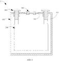
FIG. 1 is a cross-sectional view of a battery cell in one direction according to an embodiment of this application; -
FIG. 2 is a cross-sectional view of a sealing plug inFIG. 1 ; -
FIG. 3 is a schematic diagram of an electric apparatus according to an embodiment of this application. -
- 1. battery cell; 101. accommodating cavity; 102. through hole;
- 100. housing;
- 200. electrode assembly;
- 300. pole;
- 400. sealing plug; 410. first fixed portion; 420. thermally deformable portion; 411. base part; 412. extension part; 421. thermally deformable element; 422. second fixed portion; 4211. body; 4212. first annular boss; 4213. second annular boss; 4214. first annular flange; 4215. second annular flange; 42111. first connecting unit; 42112. second connecting unit; 401. first via hole; 402. second via hole; 403. groove;
- 2. electric apparatus.
- For ease of understanding this application, the following describes this application in detail with reference to accompanying drawings and specific embodiments. It should be noted that when an element is expressed as being "fastened/fixed/mounted" to another element, it may be directly fastened/fixed/mounted to the another element or one or more intermediate elements may be present. When an element is expressed as being "connected" to another element, it may be directly connected to the another element or one or more intermediate elements may be present. The terms "vertical", "horizontal", "left", "right", "inside", "outside", and similar expressions used in this specification are merely for description purposes.
- Unless otherwise defined, all technical and scientific terms used in this specification shall have the same meanings as commonly understood by persons skilled in the art to which this application belongs. The terms used in this specification of this application are merely intended to describe specific embodiments but not intended to constitute any limitation on this application. The term "and/or" used in this specification includes any and all combinations of one or more relevant listed items.
- In addition, technical features in different embodiments of this application described below can be combined with each other as long as they do not conflict with each other.
- In this specification, "mount" includes fixing or limiting an element or apparatus to a specific location or place by means of welding, screwing, clamping, bonding, or the like. The element or apparatus may stay still at the specific position or place or move within a limited range. After being fastened or limited to the specific location or place, the element or apparatus may be detachable or nondetachable. This is not limited in the embodiments of this application.
- Refer to
FIG. 1 to FIG. 2 that respectively show a cross-sectional view of a battery cell 1 in a direction and a cross-sectional view of a sealing plug according to an embodiment of this application. The battery cell 1 includes ahousing 100, anelectrode assembly 200, apole 300, and a sealingplug 400. Thehousing 100 is provided with anaccommodating cavity 101 inside, and is provided with a throughhole 102 that communicates with both theaccommodating cavity 101 and an external environment of the battery cell 1. Theelectrode assembly 200 is accommodated in theaccommodating cavity 101. Thepole 300 penetrates through thehousing 100, with one end electrically connected to theelectrode assembly 200, and the other end extending out of thehousing 100. The sealingplug 400 seals the throughhole 102, and includes a thermallydeformable portion 420, where the thermallydeformable portion 420 covers at least part of the throughhole 102, and the thermallydeformable portion 420 is configured to at least partially deform when temperature is higher than a preset threshold, so that theaccommodating cavity 101 communicates with the external environment. It is worth mentioning that the "preset threshold" in this application means a temperature value where, when temperature of the battery cell 1 rises to this value, the thermallydeformable portion 420 deforms by the exact amount to allow theaccommodating cavity 101 to communicate with the external environment. When temperature of the battery cell 1 is higher than the preset threshold, theaccommodating cavity 101 is already in communication with the external environment. The preset threshold is a temperature value that is higher than a normal operating temperature of the battery cell 1, and lower than a thermal runaway temperature of the battery cell 1. In other words, when the battery cell 1 is in a normal operating state, its temperature is lower than the preset threshold, avoiding electrolyte leakage due to communication between the internalaccommodating cavity 101 and the external environment during normal operation of the battery cell 1; when the battery cell 1 is in thermal runaway, its temperature is higher than the preset threshold, avoiding explosion of the battery cell caused by failure in discharging internal gas in time when thermal runaway occurs in the battery cell 1. It is worth adding here that "deform" mentioned in this application specifically includes hot melt, shrink and expand. - For the
housing 100, refer toFIG. 1 . Theentire housing 100 is a flat cuboid, and is provided with theaccommodating cavity 101 inside that is configured to accommodate theelectrode assembly 200 and electrolyte. In this embodiment, the battery cell 1 is a steel shell battery cell, that is, thehousing 100 is a steel shell. It can be understood that in other embodiments of this application, the battery cell 1 may alternatively be other types of hard shell battery cells, that is, thehousing 100 is a shell of other metals such as aluminum. In addition, thehousing 100 is further provided with the throughhole 102, where the throughhole 102 communicates with both theaccommodating cavity 101 and the external environment of the battery cell 1. In this embodiment, the throughhole 102 is an electrolyte injection hole of the battery cell 1, and electrolyte is injected into theaccommodating cavity 101 through the throughhole 102. It should be understood that in other embodiments of this application, the throughhole 102 may alternatively be other hole-like structures separate from an electrolyte injection hole. That is, the battery cell 1 has an injection hole and a throughhole 102 that are separate from each other. - For the
electrode assembly 200, refer toFIG. 1 . Theelectrode assembly 200 is accommodated in theaccommodating cavity 101, and includes a first electrode plate (not shown in the figure), a second electrode plate (not shown in the figure), and a separator (not shown in the figure) that are stacked. The first electrode plate and the second electrode plate have opposite polarities and are spaced apart. One of them is a positive electrode plate, and the other is a negative electrode plate. The separator is arranged between the two electrode plates to separate them. The first electrode plate, second electrode plate, and separator are stacked and the resulting stack is wound into a cylindrical structure with an oblong cross section, for ease of being accommodated in theaccommodating cavity 101. It can be understood that although theelectrode assembly 200 in this embodiment is a wound electrode assembly, this application is not limited thereto. In other embodiments of this application, theelectrode assembly 200 may alternatively be a laminated electrode assembly. Thehousing 100 is further filled with electrolyte. The electrolyte infiltrates into theelectrode assembly 200. The electrolyte is used to provide an environment for conduction of lithium ions, so that lithium ions can be duly intercalated into the first electrode plate or the second electrode plate, thereby implementing charging or discharging of the battery cell 1. - For the
pole 300, refer toFIG. 1 . Thepole 300 runs through thehousing 100 and is fastened to thehousing 100. One end of thepole 300 extends into theaccommodating cavity 101 and is electrically connected to the electrode plate in theelectrode assembly 200; the other end of thepole 300 extends out of thehousing 100 and is electrically connected to an external load, thereby supplying power to the load. The battery cell 1 includes twopoles 300, where onepole 300 is electrically connected to the first electrode plate, and theother pole 300 is electrically connected to the second electrode plate. - For the sealing
plug 400, specifically refer toFIG. 2 andFIG. 1 . The sealingplug 400 is provided in the throughhole 102 and seals the throughhole 102. In this embodiment, the sealingplug 400 includes the first fixedportion 410 and the thermallydeformable portion 420. The first fixedportion 410 is fastened to thehousing 100 and is provided with the first viahole 401 that communicates with theaccommodating cavity 101. The first viahole 401 may directly communicate with theaccommodating cavity 101 or indirectly communicate with theaccommodating cavity 101 by connecting to an end of the throughhole 102 at the side of theaccommodating cavity 101. The thermallydeformable portion 420 is disposed in the first viahole 401 and seals the first viahole 401, and the thermallydeformable portion 420 is configured to at least partially deform when temperature is higher than the preset threshold, so that theaccommodating cavity 101, the first viahole 401, and the external environment of the battery cell 1 communicate sequentially, allowing gas at two sides of the thermallydeformable portion 420 to communicate with each other. - The entire first fixed
portion 410 is a rotary structure, including thebase part 411 and theextension part 412. Specifically, thebase part 411 is a flat columnar structure, which at least partially extends into the throughhole 102. Thebase part 411 is provided with the first viahole 401 in the middle, and two ends of the first viahole 401 respectively communicate with an interior of thehousing 100 and the external environment. An end of thebase part 411 away from theaccommodating cavity 101 extends outward to form theextension part 412. Theextension part 412 is arranged around thebase part 411 and fastened to the outer surface of thehousing 100. Optionally, the first fixedportion 410 contains metal. For example, the first fixedportion 410 is made of carbon steel, and then the first fixedportion 410 can be conveniently fastened to thehousing 100 by welding. It can be understood that the material of the first fixedportion 410 is not specifically limited in this application. For example, in other embodiments of this application, the first fixedportion 410 may alternatively be made of nonmetallic materials such as plastic that provides good heat resistance. Likewise, a connection manner of the first fixedportion 410 and thehousing 100 is not specifically limited in this application. For example, in other embodiments of this application, the first fixedportion 410 may alternatively be fastened to thehousing 100 by bonding, screwing, or the like. Examples are not provided one by one herein. - The thermally
deformable portion 420 includes a thermallydeformable element 421. The thermallydeformable element 421 is disposed in the first viahole 401 and is configured to deform when temperature is higher than the preset threshold, so that theaccommodating cavity 101, the first viahole 401, and the external environment communicate sequentially. The thermallydeformable element 421 includes abody 4211, and thebody 4211 runs through the first viahole 401. A first end of thebody 4211 that extends into theaccommodating cavity 101 extends away from an axis of the first viahole 401 to form a firstannular boss 4212; the firstannular boss 4212 is arranged around thebody 4211 and is attached to one surface of the first fixed portion that faces toward the accommodating cavity. A second end of thebody 4211 that extends out of the first viahole 401 extends away from the axis of the first viahole 401 to form a secondannular boss 4213; the secondannular boss 4213 is arranged around thebody 4211 and is attached to one surface of the first fixedportion 410 that faces away from theaccommodating cavity 101. As such, two ends of the thermallydeformable element 421 tightly clamp the first fixedportion 410 in an axial direction of the first viahole 401, so that the thermallydeformable element 421 is fastened to the first fixedportion 410. - In some embodiments, for the battery cell 1, a normal operating temperature is lower than 100°C, and a thermal runaway temperature is 150°C. Considering that thermal shrinkage can achieve the purpose of pressure relief, the thermally
deformable element 421 is preferably made of a material with a melting point between 110°C and 170°C. Optionally, when the thermallydeformable element 421 is designed as a hot melt or heat-shrinkable element, the thermallydeformable element 421 includes any one of polyethylene, polypropylene, polyvinyl chloride, and polypropylene ethylene, or a mixture thereof. When temperature is higher than the preset threshold, the thermallydeformable element 421 shrinks or melts, and a joint between the thermallydeformable element 421 and the first fixedportion 410 is at least partially torn and disconnected, so that a pressure relief channel is formed between the thermallydeformable element 421 and the first fixedportion 410, which communicates theaccommodating cavity 101 to the external environment. Alternatively, the thermallydeformable element 421 melts to form a channel that communicates theaccommodating cavity 101 to the external environment, so that theaccommodating cavity 101 communicates with the external environment. Further optionally, a gap is present between part of an outer surface of the thermallydeformable element 421 located between the firstannular boss 4212 and the secondannular boss 4213 and an inner surface of the first viahole 401. The gap reduces strength of connection between the thermallydeformable element 421 and the first fixedportion 410, making it easier to form the channel. Moreover, it also increases the cross-sectional size of the channel, helping improve the efficiency of pressure relief. Optionally, when the thermallydeformable element 421 is designed as a heat-expandable element, the thermally deformable element may include any one of polyamide (nylon 6) and glass, or a mixture thereof. When temperature is higher than the preset threshold, the thermallydeformable element 421 expands, and a joint between the thermallydeformable element 421 and first fixedportion 410 is at least partially torn and disconnected, so that a pressure relief channel is formed between the thermallydeformable element 421 and first fixedportion 410, which communicates theaccommodating cavity 101 to the external environment. Further optionally, a gap is present between part of an outer surface of the thermallydeformable element 421 located between the firstannular boss 4212 and the secondannular boss 4213 and an inner surface of the first viahole 401. The gap reduces strength of connection between the thermallydeformable element 421 and the first fixedportion 410, making it easier to form the channel. Moreover, it also provides space for expansion of the thermallydeformable element 421. - In some embodiments, the thermally
deformable portion 420 further includes a second fixedportion 422. Specifically, still referring toFIG. 2 , the thermallydeformable element 421 is provided with a second viahole 402 in the middle, and two ends of the second viahole 402 respectively communicate with theaccommodating cavity 101 and the external environment of the battery cell 1. One end of the second viahole 402 that faces toward theaccommodating cavity 101 may directly communicate with theaccommodating cavity 101, or may indirectly communicate with theaccommodating cavity 101 by communicating with an end of the throughhole 102 at the side of theaccommodating cavity 101. The second fixedportion 422 is provided in the second viahole 402 and seals the second viahole 402. Specifically, an inner surface of the second viahole 402 recesses to form agroove 403 surrounding the second viahole 402, a first annular flange 4214 protruding out of an annular wall surface of thegroove 403 is formed at a side of the body in thegroove 403 that is close to theaccommodating cavity 101, and a secondannular flange 4215 protruding out of the annular wall surface of thegroove 403 is formed at a side of the body in thegroove 403 that is away from theaccommodating cavity 101. The second fixedportion 422 is received in thegroove 403, that is, received between the first annular flange 4214 and the secondannular flange 4215, so as to seal the second viahole 402. The thermallydeformable element 421 cannot go though from being heated to being hot melted at one instance, it has to undergo thermal expansion or thermal shrinkage first. Provision of the second fixedportion 422 allows high temperature and high pressure gas inside the battery cell 1 to discharge through the gap between the thermallydeformable element 421 and the first fixedportion 410, and discharge through the gap between the thermallydeformable element 421 and the second fixedportion 422 after the thermallydeformable element 421 shrinks by such amount that joints between it and the components connected (the first fixed portion and the second fixed portion) are at least partially disconnected. In addition, the provision of the second fixedportion 422 can also reduce a total volume of the thermallydeformable element 421, so that the thermallydeformable element 421 can easily change its form to, for example, shrink or melt when heated. In conclusion, the provision of the second fixedportion 422 improves the efficiency of pressure relief for the battery cell 1 and enhances the thermal sensitivity of the thermallydeformable element 421. In this embodiment, the second fixedportion 422 contains metal. For example, the first fixedportion 410 is made of carbon steel. It can be understood that the material of the second fixedportion 422 is not specifically limited in this application. For example, in other embodiments of this application, the second fixedportion 422 may alternatively be made of nonmetallic materials such as plastic that provides good heat resistance. - In some embodiments, the
body 4211 of the thermallydeformable element 421 includes a first connectingunit 42111 and a second connectingunit 42112 that are mutually connected in an axial direction of the first viahole 401. The firstannular boss 4212 extends outward from an outer surface of the first connectingunit 42111, the secondannular boss 4213 extends outward from an outer surface of the second connectingunit 42112, the first annular flange 4214 extends inward from an inner surface of the first connectingunit 42111, and the secondannular flange 4215 extends inward from an inner surface of the second connectingunit 42112. Ends of the first connectingunit 42111 and second connectingunit 42112 that are close to each other are fastened to each other through hot melting. The firstannular boss 4212 and the secondannular boss 4213 are both fastened to the first fixedportion 410 through hot melting. The first annular flange 4214 and the secondannular flange 4215 are both fastened to the second fixedportion 422 through hot melting. In this connection manner, the first connectingunit 42111 and the second connectingunit 42112 are separately molded, and all components are fastened to each other through hot melting. Such assembly process requires no additional material such as sealant to implement sealing at joints of the components in the sealingplug 400. Certainly, the joints of the components in the sealingplug 400 may be additionally coated with sealant for secondary sealing in actual manufacturing, so as to achieve a better sealing effect. Moreover, the first connectingunit 42111 and the second connectingunit 42112 may be designed to have a same size, thereby achieving better interchangeability. It should be understood that although the thermallydeformable element 421, second fixedportion 422, and first fixedportion 410 are fastened to each other through hot melting, this application is not limited thereto. In other embodiments of this application, the thermallydeformable element 421, second fixedportion 422, and first fixedportion 410 may be fastened in other manners. For example, in some embodiments, the first fixedportion 410, the thermallydeformable element 421, and the second fixedportion 422 are integrally formed by injection molding. Specifically, the first fixedportion 410 and the second fixedportion 420 are received in an injection mold, and polyethylene (or other optional materials such as polypropylene, polyvinyl chloride, and polypropylene) is injected to the injection mold to form an integrated sealing plug. - It should be noted that, based on the foregoing embodiments, a cross-sectional profile of
any one of the firstannular boss 4212, secondannular boss 4213, first annular flange 4214, and secondannular flange 4215 may be circular, but is not limited thereto. The profile may alternatively be square or other polygonal shapes, which is not specifically limited herein. That is, the above structures are not limited to hollow cylindrical structures. - The battery cell provided in the embodiments of this application includes the
housing 100,electrode assembly 200,pole 300, and sealingplug 400. Thehousing 100 is provided with theaccommodating cavity 101 inside, and the throughhole 102 that communicates with both theaccommodating cavity 101 and the external environment of the battery cell 1. The sealingplug 400 seals the throughhole 102, and includes a thermallydeformable portion 420, where the thermallydeformable portion 420 covers at least part of the throughhole 102, and the thermallydeformable portion 420 is configured to at least partially deform when temperature is higher than a preset threshold, so that theaccommodating cavity 101 communicates with the external environment. - Compared with existing battery cells on the market, the battery cell 1 provided in the embodiments of this application has the thermally
deformable portion 420 inside that deforms when temperature is higher than the preset threshold and about to cause swelling, so that a channel is formed between the sealingplug 400 and thehousing 100, communicating theaccommodating cavity 101 to the external environment, thereby discharging the high pressure gas inside theaccommodating cavity 101 to the external environment. In other words, the battery cell 1 provided in the embodiments of this application can relieve the current situation that battery cells are unable to discharge internal gas in time when temperature is higher than a specified temperature. - It should be understood that, even though the sealing
plug 400 of the battery cell 1 in the foregoing embodiments include both the first fixedportion 410 and the thermallydeformable portion 420, in other embodiments of this application, the sealingplug 400 may include only the thermallydeformable portion 420, or even only the thermallydeformable element 421, as long as it is ensured that the thermallydeformable portion 420 covers at least part of the through hole of thehousing 100, so that the sealingplug 400 at least partially deforms when temperature is higher than the preset threshold to cause communication between theaccommodating cavity 101 and the external environment of the battery cell. For example, the thermallydeformable portion 420 is fastened to the outer surface of thehousing 100, and completely seals the throughhole 102, so as to avoid electrolyte leakage during normal operation. The thermallydeformable portion 420 is still made of a material of such properties that the thermallydeformable portion 420 is still configured to at least partially deform when temperature is higher than the preset threshold. When temperature is higher than the preset threshold, the thermallydeformable element 420 shrinks or expands, and a joint between the thermallydeformable element 420 and thehousing 100 is at least partially torn and disconnected, so as to communicate theaccommodating cavity 101 to the external environment. Alternatively, the thermallydeformable element 420 melts to form a channel that communicates theaccommodating cavity 101 to the external environment, so that theaccommodating cavity 101 communicates with the external environment. - Based on the same inventive concept, an embodiment of this application further provides a sealing plug, as shown in
FIG. 1 andFIG. 2 . The sealing plug is applied to a battery cell, and is of the same structure as the sealingplug 400 in any one of the foregoing embodiments. The battery cell includes a housing, the housing is provided with a through hole, and the sealing plug is configured to seal the through hole. Optionally, the through hole is an electrolyte injection hole of the battery cell, that is, the sealing plug in this embodiment is an injection plug configured to seal the electrolyte injection hole. Therefore it is not necessary to provide the battery cell with both an electrolyte injection hole and the through hole that are separate from each other. This can not only shorten the preparation cycle of a battery cell, but also reduce the probability of electrolyte leakage of the battery cell with a reduced quantity of holes. - In a case that the sealing plug provided in this embodiment of this application is applied to a battery cell, the sealing plug can deform when temperature is higher than the preset threshold, so as to form a channel that communicates the accommodating cavity inside the battery cell to the external environment, thereby discharging high pressure gas inside the accommodating cavity. In other words, the sealing plug provided in this embodiment of this application can relieve the current situation that battery cells are unable to discharge internal gas in time when temperature is higher than a specified temperature.
- Based on the same inventive concept, an embodiment of this application further provides an electric apparatus.
FIG. 3 is a schematic diagram of anelectric apparatus 2 according to an embodiment of this application. Theelectric apparatus 2 includes the battery cell 1 in any one of the foregoing embodiments. Theelectric apparatus 2 in this embodiment is a mobile phone. It can be understood that in other embodiments of this application, theelectric apparatus 2 may alternatively be other electric apparatuses powered by electricity such as a tablet computer, a laptop computer, and a drone. - Because the battery cell 1 is included, the battery cell in the
electric apparatus 2 provided in this embodiment of this application can also improve the current situation that battery cells are unable to discharge internal gas in time when temperature is higher than a specified temperature, which in turn improves the safety performance of the electric apparatus. - Finally, it should be noted that the foregoing embodiments are merely intended to describe the technical solutions of this application, and are not intended to limit this application. Under the idea of this application, the foregoing embodiments or the technical features in different embodiments can be combined, the steps can be implemented in any order, and there are many other variations in different aspects of this application as described above, which, for the sake of brevity, are not provided in detail. Although this application is described in detail with reference to the foregoing embodiments, persons of ordinary skill in the art should understand that modifications can be made to the technical solutions described in the foregoing embodiments, or equivalent substitutions can be made for some technical features therein, and these modifications or substitutions do not make the essence of the corresponding technical solutions depart from the scope of the technical solutions of the embodiments of this application.
Claims (11)
- A sealing plug (400), applied to a battery cell (1), wherein the battery cell (1) comprises a housing (100), the housing (100) is provided with a through hole (102), and the sealing plug (400) is configured to seal the through hole (102), characterized in that, the sealing plug (400) comprises:
a thermally deformable portion (420), the thermally deformable portion (420) covers at least a part of the through hole (102), and the thermally deformable portion (420) is configured to at least partially deform when a temperature of the battery cell (1) is higher than a preset threshold, so that the accommodating cavity (101) communicates with the external environment. - The sealing plug (400) according to claim 1, characterized in that the sealing plug (400) further comprises a first fixed portion (410);the first fixed portion (410) is fastened to an outer surface of the housing (100), and is provided with a first via hole (401) communicating with the accommodating cavity (101); andthe thermally deformable portion (420) is disposed in the first via hole (401) and seals the first via hole (401), and the thermally deformable portion (420) is configured to at least partially deform when the temperature of the battery cell (1) is higher than the preset threshold, so that the accommodating cavity (101), the first via hole (401), and the external environment communicate sequentially.
- The sealing plug (400) according to claim 2, characterized in that the first fixed portion (410) comprises a base part (411) and an extension part (412);the base part (411) at least partially extends into the through hole (102), and the base part (411) is provided with the first via hole (401); andthe extension part (412) is formed by extending a side wall of the base part (411) outward, and the extension part (412) is fastened to the outer surface of the housing (100) .
- The sealing plug (400) according to claim 2 or 3, characterized in that the thermally deformable portion (420) comprises a thermally deformable element (421), wherein the thermally deformable element (421) comprises:a body (4211), wherein the body (4211) runs through the first via hole (401);a first annular boss (4212), wherein the first annular boss (4212) is formed by extending an end of the body (4211) that extends into the accommodating cavity (101) away from an axis of the first via hole (401), and the first annular boss (4212) is arranged around the body (4211) and is attached to a surface of the first fixed portion (410) that faces toward the accommodating cavity (101); anda second annular boss (4213), wherein the second annular boss (4213) is formed by extending an end of the body (4211) that extends out of the housing (100) away from the axis of the first via hole (401), and the second annular boss (4213) is arranged around the body (4211) and is attached to a surface of the first fixed portion (410) that faces away from the accommodating cavity (101); andthe thermally deformable element (421) is configured to deform when the temperature of the battery cell (1) is higher than the preset threshold, so that the accommodating cavity (101), the first via hole (401), and the external environment communicate sequentially.
- The sealing plug (400) according to any one of claims 1 to 4, characterized in that, the thermally deformable portion (420) further comprises a second fixed portion (422); and
the thermally deformable element (421) is provided with a second via hole (402) communicating the accommodating cavity (101) to the external environment, and the second fixed portion (422) is provided in the second via hole (402) and seals the second via hole (402). - The sealing plug (400) according to claim 5, characterized in that, an inner surface surrounding the second via hole (402) have a recess formed in form of a groove (403), and the second fixed portion (422) is received in the groove (403).
- The sealing plug (400) according to claim 5 or 6, characterized in that, the body (4211) comprises a first connecting unit (42111) and a second connecting unit (42112) that are mutually connected in an axial direction of the first via hole (401);a first annular flange (4214) protruding out of an annular wall surface of the groove (403) is formed at a side of the body (4211) closer to the accommodating cavity (101), and a second annular flange (4215) protruding out of the annular wall surface of the grooves (403) formed at a side of the body (4211) away from the accommodating cavity (101);the first annular boss (4212) extends from an outer surface of the first connecting unit (42111), the second annular boss (4213) extends from an outer surface of the second connecting unit (42112), the first annular flange (4214) extends from an inner surface of the first connecting unit (42111), and the second annular flange (4215) extends from an inner surface of the second connecting unit (42112); andthe first connecting unit (42111) and the second connecting unit (42112) are fastened to each other through hot melting, the first annular boss (4212) and the first fixed portion (410) are fastened to each other through hot melting, the second annular boss (4213) and the first fixed portion (410) are fastened to each other through hot melting; the first annular flange (4214) and the second fixed portion (422) are fastened to each other through hot melting; and the second annular flange (4215) and the second fixed portion (422) are fastened to each other through hot melting.
- The sealing plug (400) according to any one of claims 5 to 7, characterized in that, the first fixed portion (410) comprises a metal; and/orthe second fixed portion (422) comprises the metal; and/orthe thermally deformable element (421) comprises at least one selected from the group consisting of polyethylene, polypropylene, polyvinyl chloride, and polypropylene ethylene.
- The battery cell (1) according to any one of claims 1 to 8, characterized in that, the thermally deformable portion (420) is configured to at least partially melt, or expand, or shrink when the temperature of the battery cell (1) is higher than the preset threshold, so that the thermally deformable portion (420) and a connected part are at least partially disconnected at a joint.
- A battery cell (1), characterized by comprising a housing (100) and the sealing plug (400) according to any one of claims 1 to 9, wherein the housing (100) is provided with an accommodating cavity (101) inside, the through hole (102) is configured to communicate with both the accommodating cavity (101) and an external environment of the battery cell (1).
- An electric apparatus (2), characterized by comprising the battery cell (1) according to claim 10.
Applications Claiming Priority (1)
| Application Number | Priority Date | Filing Date | Title |
|---|---|---|---|
| CN202110340938.8A CN113131083B (en) | 2021-03-30 | 2021-03-30 | Batteries, sealing plugs and electrical devices |
Publications (2)
| Publication Number | Publication Date |
|---|---|
| EP4068487A1 true EP4068487A1 (en) | 2022-10-05 |
| EP4068487B1 EP4068487B1 (en) | 2025-09-24 |
Family
ID=76774858
Family Applications (1)
| Application Number | Title | Priority Date | Filing Date |
|---|---|---|---|
| EP22164781.1A Active EP4068487B1 (en) | 2021-03-30 | 2022-03-28 | Sealing plug, battery cell, and electric apparatus |
Country Status (3)
| Country | Link |
|---|---|
| EP (1) | EP4068487B1 (en) |
| JP (1) | JP7451582B2 (en) |
| CN (1) | CN113131083B (en) |
Cited By (1)
| Publication number | Priority date | Publication date | Assignee | Title |
|---|---|---|---|---|
| CN114759321A (en) * | 2022-05-24 | 2022-07-15 | 厦门海辰新能源科技有限公司 | Battery and sealing method |
Families Citing this family (3)
| Publication number | Priority date | Publication date | Assignee | Title |
|---|---|---|---|---|
| CN114039175B (en) * | 2021-10-18 | 2024-06-04 | 宁德新能源科技有限公司 | A battery cell and an electric device |
| CN114583341A (en) * | 2022-04-29 | 2022-06-03 | 宁德时代新能源科技股份有限公司 | Battery cell and its manufacturing method and manufacturing system, battery, electric device |
| CN119651039A (en) * | 2022-12-31 | 2025-03-18 | 宁德新能源科技有限公司 | Pressure relief mechanism, battery cell and electrical device |
Citations (4)
| Publication number | Priority date | Publication date | Assignee | Title |
|---|---|---|---|---|
| US2766408A (en) * | 1954-12-06 | 1956-10-09 | Gen Motors Corp | Vent plug for electrolytic capacitor |
| US4397919A (en) * | 1979-03-22 | 1983-08-09 | Standard Oil Company | Explosion resistant battery cells |
| US20100136391A1 (en) * | 2009-09-12 | 2010-06-03 | Tesla Motors, Inc. | Active Thermal Runaway Mitigation System for Use Within a Battery Pack |
| WO2020081372A1 (en) * | 2018-10-15 | 2020-04-23 | Electric Power Systems, LLC | Thermal management of electrochemical storage devices |
Family Cites Families (6)
| Publication number | Priority date | Publication date | Assignee | Title |
|---|---|---|---|---|
| US4804593A (en) * | 1986-05-20 | 1989-02-14 | Sanyo Electric Co., Ltd. | Enclosed cell having safety valve mechanism and fabricating method of the same |
| EP0948065B1 (en) * | 1998-03-30 | 2003-06-04 | Renata AG | Safety vent for accumulator or battery |
| EP1217670A1 (en) * | 2000-12-21 | 2002-06-26 | Renata AG | Safety valve to improve shelf life of a battery |
| CN206685432U (en) * | 2017-02-27 | 2017-11-28 | 比亚迪股份有限公司 | A kind of battery cover board assembly and battery |
| CN206849873U (en) * | 2017-05-05 | 2018-01-05 | 深圳市科达利实业股份有限公司 | The battery cover plate structure and battery of rupture pressure disc are destroyed when a kind of heated |
| CN207834423U (en) * | 2018-01-07 | 2018-09-07 | 合肥国轩高科动力能源有限公司 | A lithium battery explosion-proof case |
-
2021
- 2021-03-30 CN CN202110340938.8A patent/CN113131083B/en active Active
-
2022
- 2022-02-25 JP JP2022027998A patent/JP7451582B2/en active Active
- 2022-03-28 EP EP22164781.1A patent/EP4068487B1/en active Active
Patent Citations (4)
| Publication number | Priority date | Publication date | Assignee | Title |
|---|---|---|---|---|
| US2766408A (en) * | 1954-12-06 | 1956-10-09 | Gen Motors Corp | Vent plug for electrolytic capacitor |
| US4397919A (en) * | 1979-03-22 | 1983-08-09 | Standard Oil Company | Explosion resistant battery cells |
| US20100136391A1 (en) * | 2009-09-12 | 2010-06-03 | Tesla Motors, Inc. | Active Thermal Runaway Mitigation System for Use Within a Battery Pack |
| WO2020081372A1 (en) * | 2018-10-15 | 2020-04-23 | Electric Power Systems, LLC | Thermal management of electrochemical storage devices |
Cited By (2)
| Publication number | Priority date | Publication date | Assignee | Title |
|---|---|---|---|---|
| CN114759321A (en) * | 2022-05-24 | 2022-07-15 | 厦门海辰新能源科技有限公司 | Battery and sealing method |
| CN114759321B (en) * | 2022-05-24 | 2024-03-08 | 厦门海辰储能科技股份有限公司 | Battery and sealing method |
Also Published As
| Publication number | Publication date |
|---|---|
| JP7451582B2 (en) | 2024-03-18 |
| CN113131083A (en) | 2021-07-16 |
| EP4068487B1 (en) | 2025-09-24 |
| CN113131083B (en) | 2023-10-13 |
| JP2022068356A (en) | 2022-05-09 |
Similar Documents
| Publication | Publication Date | Title |
|---|---|---|
| EP4068487A1 (en) | Sealing plug, battery cell, and electric apparatus | |
| EP4071897A1 (en) | End cap assembly, battery cell and manufacturing method therefor, battery and power device | |
| JP7482160B2 (en) | Pole assemblies, battery cells and electrical equipment | |
| WO2023134422A1 (en) | End cover assembly, battery cell, battery and electrical apparatus | |
| KR102541167B1 (en) | Sealing assembly for sealing through-holes, method and apparatus for manufacturing battery cells | |
| US20240234995A1 (en) | Battery cell and electrical device | |
| US11264663B2 (en) | Battery cover assembly, single-cell battery, battery module, power battery pack, and electric vehicle | |
| JP7614225B2 (en) | Batteries and Powered Devices | |
| KR20170024417A (en) | Rechargeable battery | |
| WO2023155674A1 (en) | Battery cell, battery, electrical device, and method and apparatus for manufacturing battery cell | |
| US20250070432A1 (en) | Battery cell, battery, and electric device | |
| CN120527534A (en) | Cover assembly, battery and electrical device | |
| KR20160008272A (en) | A terminal assembly, insulation plate and secondary cell comprising the same | |
| CN117117441B (en) | Battery cell and battery pack | |
| KR20050087632A (en) | Pcm protection cap of lithium ion battery | |
| KR20190096650A (en) | Rechargeable battery | |
| KR20140004471A (en) | Battery module and terminal assembly applied for the same | |
| CN208028098U (en) | Current interrupt device, battery cover assembly, single battery, battery module, power battery and electric vehicle | |
| CN209592215U (en) | A lithium ion battery | |
| CN224204326U (en) | Battery electrode connection assembly, single cell and electrical equipment | |
| CN222867813U (en) | Cover plates, sealing components, battery cells, battery packs, electrical equipment and welding devices | |
| CN224204325U (en) | Battery connection components, individual cells and electrical devices | |
| CN222463350U (en) | Cylindrical battery monomer, battery and electric equipment | |
| CN221009176U (en) | Battery cells, battery modules and energy storage power supplies | |
| CN222927723U (en) | Battery monomer, battery and electric equipment |
Legal Events
| Date | Code | Title | Description |
|---|---|---|---|
| PUAI | Public reference made under article 153(3) epc to a published international application that has entered the european phase |
Free format text: ORIGINAL CODE: 0009012 |
|
| STAA | Information on the status of an ep patent application or granted ep patent |
Free format text: STATUS: REQUEST FOR EXAMINATION WAS MADE |
|
| 17P | Request for examination filed |
Effective date: 20220328 |
|
| AK | Designated contracting states |
Kind code of ref document: A1 Designated state(s): AL AT BE BG CH CY CZ DE DK EE ES FI FR GB GR HR HU IE IS IT LI LT LU LV MC MK MT NL NO PL PT RO RS SE SI SK SM TR |
|
| STAA | Information on the status of an ep patent application or granted ep patent |
Free format text: STATUS: EXAMINATION IS IN PROGRESS |
|
| 17Q | First examination report despatched |
Effective date: 20240822 |
|
| GRAP | Despatch of communication of intention to grant a patent |
Free format text: ORIGINAL CODE: EPIDOSNIGR1 |
|
| STAA | Information on the status of an ep patent application or granted ep patent |
Free format text: STATUS: GRANT OF PATENT IS INTENDED |
|
| INTG | Intention to grant announced |
Effective date: 20250428 |
|
| GRAS | Grant fee paid |
Free format text: ORIGINAL CODE: EPIDOSNIGR3 |
|
| GRAA | (expected) grant |
Free format text: ORIGINAL CODE: 0009210 |
|
| STAA | Information on the status of an ep patent application or granted ep patent |
Free format text: STATUS: THE PATENT HAS BEEN GRANTED |
|
| AK | Designated contracting states |
Kind code of ref document: B1 Designated state(s): AL AT BE BG CH CY CZ DE DK EE ES FI FR GB GR HR HU IE IS IT LI LT LU LV MC MK MT NL NO PL PT RO RS SE SI SK SM TR |
|
| P01 | Opt-out of the competence of the unified patent court (upc) registered |
Free format text: CASE NUMBER: UPC_APP_3603_4068487/2025 Effective date: 20250818 |
|
| REG | Reference to a national code |
Ref country code: GB Ref legal event code: FG4D |
|
| REG | Reference to a national code |
Ref country code: CH Ref legal event code: EP |
|
| REG | Reference to a national code |
Ref country code: DE Ref legal event code: R096 Ref document number: 602022021812 Country of ref document: DE |
|
| REG | Reference to a national code |
Ref country code: IE Ref legal event code: FG4D |
|
| REG | Reference to a national code |
Ref country code: NL Ref legal event code: FP |
|
| PG25 | Lapsed in a contracting state [announced via postgrant information from national office to epo] |
Ref country code: NO Free format text: LAPSE BECAUSE OF FAILURE TO SUBMIT A TRANSLATION OF THE DESCRIPTION OR TO PAY THE FEE WITHIN THE PRESCRIBED TIME-LIMIT Effective date: 20251224 |
|
| REG | Reference to a national code |
Ref country code: LT Ref legal event code: MG9D |
|
| PG25 | Lapsed in a contracting state [announced via postgrant information from national office to epo] |
Ref country code: FI Free format text: LAPSE BECAUSE OF FAILURE TO SUBMIT A TRANSLATION OF THE DESCRIPTION OR TO PAY THE FEE WITHIN THE PRESCRIBED TIME-LIMIT Effective date: 20250924 |
|
| PG25 | Lapsed in a contracting state [announced via postgrant information from national office to epo] |
Ref country code: HR Free format text: LAPSE BECAUSE OF FAILURE TO SUBMIT A TRANSLATION OF THE DESCRIPTION OR TO PAY THE FEE WITHIN THE PRESCRIBED TIME-LIMIT Effective date: 20250924 |
|
| PG25 | Lapsed in a contracting state [announced via postgrant information from national office to epo] |
Ref country code: GR Free format text: LAPSE BECAUSE OF FAILURE TO SUBMIT A TRANSLATION OF THE DESCRIPTION OR TO PAY THE FEE WITHIN THE PRESCRIBED TIME-LIMIT Effective date: 20251225 |
|
| PG25 | Lapsed in a contracting state [announced via postgrant information from national office to epo] |
Ref country code: SE Free format text: LAPSE BECAUSE OF FAILURE TO SUBMIT A TRANSLATION OF THE DESCRIPTION OR TO PAY THE FEE WITHIN THE PRESCRIBED TIME-LIMIT Effective date: 20250924 |
|
| PG25 | Lapsed in a contracting state [announced via postgrant information from national office to epo] |
Ref country code: LV Free format text: LAPSE BECAUSE OF FAILURE TO SUBMIT A TRANSLATION OF THE DESCRIPTION OR TO PAY THE FEE WITHIN THE PRESCRIBED TIME-LIMIT Effective date: 20250924 |
|
| PG25 | Lapsed in a contracting state [announced via postgrant information from national office to epo] |
Ref country code: BG Free format text: LAPSE BECAUSE OF FAILURE TO SUBMIT A TRANSLATION OF THE DESCRIPTION OR TO PAY THE FEE WITHIN THE PRESCRIBED TIME-LIMIT Effective date: 20250924 |
|
| PG25 | Lapsed in a contracting state [announced via postgrant information from national office to epo] |
Ref country code: RS Free format text: LAPSE BECAUSE OF FAILURE TO SUBMIT A TRANSLATION OF THE DESCRIPTION OR TO PAY THE FEE WITHIN THE PRESCRIBED TIME-LIMIT Effective date: 20251224 |
|
| REG | Reference to a national code |
Ref country code: AT Ref legal event code: MK05 Ref document number: 1841142 Country of ref document: AT Kind code of ref document: T Effective date: 20250924 |
|
| PGFP | Annual fee paid to national office [announced via postgrant information from national office to epo] |
Ref country code: NL Payment date: 20260213 Year of fee payment: 5 |
|
| PG25 | Lapsed in a contracting state [announced via postgrant information from national office to epo] |
Ref country code: SM Free format text: LAPSE BECAUSE OF FAILURE TO SUBMIT A TRANSLATION OF THE DESCRIPTION OR TO PAY THE FEE WITHIN THE PRESCRIBED TIME-LIMIT Effective date: 20250924 |
|
| PGFP | Annual fee paid to national office [announced via postgrant information from national office to epo] |
Ref country code: GB Payment date: 20260209 Year of fee payment: 5 |
|
| PG25 | Lapsed in a contracting state [announced via postgrant information from national office to epo] |
Ref country code: ES Free format text: LAPSE BECAUSE OF FAILURE TO SUBMIT A TRANSLATION OF THE DESCRIPTION OR TO PAY THE FEE WITHIN THE PRESCRIBED TIME-LIMIT Effective date: 20250924 |
|
| PGFP | Annual fee paid to national office [announced via postgrant information from national office to epo] |
Ref country code: DE Payment date: 20260204 Year of fee payment: 5 |
|
| PG25 | Lapsed in a contracting state [announced via postgrant information from national office to epo] |
Ref country code: AT Free format text: LAPSE BECAUSE OF FAILURE TO SUBMIT A TRANSLATION OF THE DESCRIPTION OR TO PAY THE FEE WITHIN THE PRESCRIBED TIME-LIMIT Effective date: 20250924 |
|
| PG25 | Lapsed in a contracting state [announced via postgrant information from national office to epo] |
Ref country code: IT Free format text: LAPSE BECAUSE OF FAILURE TO SUBMIT A TRANSLATION OF THE DESCRIPTION OR TO PAY THE FEE WITHIN THE PRESCRIBED TIME-LIMIT Effective date: 20250924 |
|
| PG25 | Lapsed in a contracting state [announced via postgrant information from national office to epo] |
Ref country code: IS Free format text: LAPSE BECAUSE OF FAILURE TO SUBMIT A TRANSLATION OF THE DESCRIPTION OR TO PAY THE FEE WITHIN THE PRESCRIBED TIME-LIMIT Effective date: 20260124 |
|
| PGFP | Annual fee paid to national office [announced via postgrant information from national office to epo] |
Ref country code: FR Payment date: 20260209 Year of fee payment: 5 |
|
| PG25 | Lapsed in a contracting state [announced via postgrant information from national office to epo] |
Ref country code: CZ Free format text: LAPSE BECAUSE OF FAILURE TO SUBMIT A TRANSLATION OF THE DESCRIPTION OR TO PAY THE FEE WITHIN THE PRESCRIBED TIME-LIMIT Effective date: 20250924 Ref country code: PT Free format text: LAPSE BECAUSE OF FAILURE TO SUBMIT A TRANSLATION OF THE DESCRIPTION OR TO PAY THE FEE WITHIN THE PRESCRIBED TIME-LIMIT Effective date: 20260126 |
|
| PG25 | Lapsed in a contracting state [announced via postgrant information from national office to epo] |
Ref country code: PL Free format text: LAPSE BECAUSE OF FAILURE TO SUBMIT A TRANSLATION OF THE DESCRIPTION OR TO PAY THE FEE WITHIN THE PRESCRIBED TIME-LIMIT Effective date: 20250924 |
|
| PG25 | Lapsed in a contracting state [announced via postgrant information from national office to epo] |
Ref country code: SK Free format text: LAPSE BECAUSE OF FAILURE TO SUBMIT A TRANSLATION OF THE DESCRIPTION OR TO PAY THE FEE WITHIN THE PRESCRIBED TIME-LIMIT Effective date: 20250924 Ref country code: EE Free format text: LAPSE BECAUSE OF FAILURE TO SUBMIT A TRANSLATION OF THE DESCRIPTION OR TO PAY THE FEE WITHIN THE PRESCRIBED TIME-LIMIT Effective date: 20250924 |