EP4068457A1 - Power storage device - Google Patents
Power storage device Download PDFInfo
- Publication number
- EP4068457A1 EP4068457A1 EP22157737.2A EP22157737A EP4068457A1 EP 4068457 A1 EP4068457 A1 EP 4068457A1 EP 22157737 A EP22157737 A EP 22157737A EP 4068457 A1 EP4068457 A1 EP 4068457A1
- Authority
- EP
- European Patent Office
- Prior art keywords
- electrode
- negative
- positive
- power storage
- protrusion
- Prior art date
- Legal status (The legal status is an assumption and is not a legal conclusion. Google has not performed a legal analysis and makes no representation as to the accuracy of the status listed.)
- Granted
Links
Images



Classifications
-
- H—ELECTRICITY
- H01—ELECTRIC ELEMENTS
- H01M—PROCESSES OR MEANS, e.g. BATTERIES, FOR THE DIRECT CONVERSION OF CHEMICAL ENERGY INTO ELECTRICAL ENERGY
- H01M50/00—Constructional details or processes of manufacture of the non-active parts of electrochemical cells other than fuel cells, e.g. hybrid cells
- H01M50/50—Current conducting connections for cells or batteries
- H01M50/531—Electrode connections inside a battery casing
- H01M50/54—Connection of several leads or tabs of plate-like electrode stacks, e.g. electrode pole straps or bridges
-
- H—ELECTRICITY
- H01—ELECTRIC ELEMENTS
- H01M—PROCESSES OR MEANS, e.g. BATTERIES, FOR THE DIRECT CONVERSION OF CHEMICAL ENERGY INTO ELECTRICAL ENERGY
- H01M50/00—Constructional details or processes of manufacture of the non-active parts of electrochemical cells other than fuel cells, e.g. hybrid cells
- H01M50/50—Current conducting connections for cells or batteries
- H01M50/502—Interconnectors for connecting terminals of adjacent batteries; Interconnectors for connecting cells outside a battery casing
- H01M50/507—Interconnectors for connecting terminals of adjacent batteries; Interconnectors for connecting cells outside a battery casing comprising an arrangement of two or more busbars within a container structure, e.g. busbar modules
-
- H—ELECTRICITY
- H01—ELECTRIC ELEMENTS
- H01M—PROCESSES OR MEANS, e.g. BATTERIES, FOR THE DIRECT CONVERSION OF CHEMICAL ENERGY INTO ELECTRICAL ENERGY
- H01M10/00—Secondary cells; Manufacture thereof
- H01M10/05—Accumulators with non-aqueous electrolyte
- H01M10/052—Li-accumulators
- H01M10/0525—Rocking-chair batteries, i.e. batteries with lithium insertion or intercalation in both electrodes; Lithium-ion batteries
-
- H—ELECTRICITY
- H01—ELECTRIC ELEMENTS
- H01M—PROCESSES OR MEANS, e.g. BATTERIES, FOR THE DIRECT CONVERSION OF CHEMICAL ENERGY INTO ELECTRICAL ENERGY
- H01M10/00—Secondary cells; Manufacture thereof
- H01M10/05—Accumulators with non-aqueous electrolyte
- H01M10/058—Construction or manufacture
- H01M10/0585—Construction or manufacture of accumulators having only flat construction elements, i.e. flat positive electrodes, flat negative electrodes and flat separators
-
- H—ELECTRICITY
- H01—ELECTRIC ELEMENTS
- H01M—PROCESSES OR MEANS, e.g. BATTERIES, FOR THE DIRECT CONVERSION OF CHEMICAL ENERGY INTO ELECTRICAL ENERGY
- H01M50/00—Constructional details or processes of manufacture of the non-active parts of electrochemical cells other than fuel cells, e.g. hybrid cells
- H01M50/10—Primary casings; Jackets or wrappings
- H01M50/116—Primary casings; Jackets or wrappings characterised by the material
- H01M50/124—Primary casings; Jackets or wrappings characterised by the material having a layered structure
-
- H—ELECTRICITY
- H01—ELECTRIC ELEMENTS
- H01M—PROCESSES OR MEANS, e.g. BATTERIES, FOR THE DIRECT CONVERSION OF CHEMICAL ENERGY INTO ELECTRICAL ENERGY
- H01M50/00—Constructional details or processes of manufacture of the non-active parts of electrochemical cells other than fuel cells, e.g. hybrid cells
- H01M50/10—Primary casings; Jackets or wrappings
- H01M50/172—Arrangements of electric connectors penetrating the casing
- H01M50/174—Arrangements of electric connectors penetrating the casing adapted for the shape of the cells
- H01M50/178—Arrangements of electric connectors penetrating the casing adapted for the shape of the cells for pouch or flexible bag cells
-
- H—ELECTRICITY
- H01—ELECTRIC ELEMENTS
- H01M—PROCESSES OR MEANS, e.g. BATTERIES, FOR THE DIRECT CONVERSION OF CHEMICAL ENERGY INTO ELECTRICAL ENERGY
- H01M50/00—Constructional details or processes of manufacture of the non-active parts of electrochemical cells other than fuel cells, e.g. hybrid cells
- H01M50/20—Mountings; Secondary casings or frames; Racks, modules or packs; Suspension devices; Shock absorbers; Transport or carrying devices; Holders
- H01M50/249—Mountings; Secondary casings or frames; Racks, modules or packs; Suspension devices; Shock absorbers; Transport or carrying devices; Holders specially adapted for aircraft or vehicles, e.g. cars or trains
-
- H—ELECTRICITY
- H01—ELECTRIC ELEMENTS
- H01M—PROCESSES OR MEANS, e.g. BATTERIES, FOR THE DIRECT CONVERSION OF CHEMICAL ENERGY INTO ELECTRICAL ENERGY
- H01M50/00—Constructional details or processes of manufacture of the non-active parts of electrochemical cells other than fuel cells, e.g. hybrid cells
- H01M50/50—Current conducting connections for cells or batteries
- H01M50/502—Interconnectors for connecting terminals of adjacent batteries; Interconnectors for connecting cells outside a battery casing
-
- H—ELECTRICITY
- H01—ELECTRIC ELEMENTS
- H01M—PROCESSES OR MEANS, e.g. BATTERIES, FOR THE DIRECT CONVERSION OF CHEMICAL ENERGY INTO ELECTRICAL ENERGY
- H01M50/00—Constructional details or processes of manufacture of the non-active parts of electrochemical cells other than fuel cells, e.g. hybrid cells
- H01M50/50—Current conducting connections for cells or batteries
- H01M50/502—Interconnectors for connecting terminals of adjacent batteries; Interconnectors for connecting cells outside a battery casing
- H01M50/503—Interconnectors for connecting terminals of adjacent batteries; Interconnectors for connecting cells outside a battery casing characterised by the shape of the interconnectors
-
- H—ELECTRICITY
- H01—ELECTRIC ELEMENTS
- H01M—PROCESSES OR MEANS, e.g. BATTERIES, FOR THE DIRECT CONVERSION OF CHEMICAL ENERGY INTO ELECTRICAL ENERGY
- H01M50/00—Constructional details or processes of manufacture of the non-active parts of electrochemical cells other than fuel cells, e.g. hybrid cells
- H01M50/50—Current conducting connections for cells or batteries
- H01M50/502—Interconnectors for connecting terminals of adjacent batteries; Interconnectors for connecting cells outside a battery casing
- H01M50/505—Interconnectors for connecting terminals of adjacent batteries; Interconnectors for connecting cells outside a battery casing comprising a single busbar
-
- H—ELECTRICITY
- H01—ELECTRIC ELEMENTS
- H01M—PROCESSES OR MEANS, e.g. BATTERIES, FOR THE DIRECT CONVERSION OF CHEMICAL ENERGY INTO ELECTRICAL ENERGY
- H01M50/00—Constructional details or processes of manufacture of the non-active parts of electrochemical cells other than fuel cells, e.g. hybrid cells
- H01M50/50—Current conducting connections for cells or batteries
- H01M50/502—Interconnectors for connecting terminals of adjacent batteries; Interconnectors for connecting cells outside a battery casing
- H01M50/509—Interconnectors for connecting terminals of adjacent batteries; Interconnectors for connecting cells outside a battery casing characterised by the type of connection, e.g. mixed connections
- H01M50/51—Connection only in series
-
- H—ELECTRICITY
- H01—ELECTRIC ELEMENTS
- H01M—PROCESSES OR MEANS, e.g. BATTERIES, FOR THE DIRECT CONVERSION OF CHEMICAL ENERGY INTO ELECTRICAL ENERGY
- H01M50/00—Constructional details or processes of manufacture of the non-active parts of electrochemical cells other than fuel cells, e.g. hybrid cells
- H01M50/50—Current conducting connections for cells or batteries
- H01M50/531—Electrode connections inside a battery casing
- H01M50/533—Electrode connections inside a battery casing characterised by the shape of the leads or tabs
-
- H—ELECTRICITY
- H01—ELECTRIC ELEMENTS
- H01M—PROCESSES OR MEANS, e.g. BATTERIES, FOR THE DIRECT CONVERSION OF CHEMICAL ENERGY INTO ELECTRICAL ENERGY
- H01M50/00—Constructional details or processes of manufacture of the non-active parts of electrochemical cells other than fuel cells, e.g. hybrid cells
- H01M50/50—Current conducting connections for cells or batteries
- H01M50/543—Terminals
- H01M50/547—Terminals characterised by the disposition of the terminals on the cells
-
- H—ELECTRICITY
- H01—ELECTRIC ELEMENTS
- H01M—PROCESSES OR MEANS, e.g. BATTERIES, FOR THE DIRECT CONVERSION OF CHEMICAL ENERGY INTO ELECTRICAL ENERGY
- H01M50/00—Constructional details or processes of manufacture of the non-active parts of electrochemical cells other than fuel cells, e.g. hybrid cells
- H01M50/50—Current conducting connections for cells or batteries
- H01M50/543—Terminals
- H01M50/547—Terminals characterised by the disposition of the terminals on the cells
- H01M50/548—Terminals characterised by the disposition of the terminals on the cells on opposite sides of the cell
-
- H—ELECTRICITY
- H01—ELECTRIC ELEMENTS
- H01M—PROCESSES OR MEANS, e.g. BATTERIES, FOR THE DIRECT CONVERSION OF CHEMICAL ENERGY INTO ELECTRICAL ENERGY
- H01M50/00—Constructional details or processes of manufacture of the non-active parts of electrochemical cells other than fuel cells, e.g. hybrid cells
- H01M50/50—Current conducting connections for cells or batteries
- H01M50/543—Terminals
- H01M50/552—Terminals characterised by their shape
- H01M50/553—Terminals adapted for prismatic, pouch or rectangular cells
-
- H—ELECTRICITY
- H01—ELECTRIC ELEMENTS
- H01M—PROCESSES OR MEANS, e.g. BATTERIES, FOR THE DIRECT CONVERSION OF CHEMICAL ENERGY INTO ELECTRICAL ENERGY
- H01M50/00—Constructional details or processes of manufacture of the non-active parts of electrochemical cells other than fuel cells, e.g. hybrid cells
- H01M50/50—Current conducting connections for cells or batteries
- H01M50/543—Terminals
- H01M50/552—Terminals characterised by their shape
- H01M50/553—Terminals adapted for prismatic, pouch or rectangular cells
- H01M50/557—Plate-shaped terminals
-
- H—ELECTRICITY
- H01—ELECTRIC ELEMENTS
- H01M—PROCESSES OR MEANS, e.g. BATTERIES, FOR THE DIRECT CONVERSION OF CHEMICAL ENERGY INTO ELECTRICAL ENERGY
- H01M2220/00—Batteries for particular applications
- H01M2220/20—Batteries in motive systems, e.g. vehicle, ship, plane
-
- Y—GENERAL TAGGING OF NEW TECHNOLOGICAL DEVELOPMENTS; GENERAL TAGGING OF CROSS-SECTIONAL TECHNOLOGIES SPANNING OVER SEVERAL SECTIONS OF THE IPC; TECHNICAL SUBJECTS COVERED BY FORMER USPC CROSS-REFERENCE ART COLLECTIONS [XRACs] AND DIGESTS
- Y02—TECHNOLOGIES OR APPLICATIONS FOR MITIGATION OR ADAPTATION AGAINST CLIMATE CHANGE
- Y02E—REDUCTION OF GREENHOUSE GAS [GHG] EMISSIONS, RELATED TO ENERGY GENERATION, TRANSMISSION OR DISTRIBUTION
- Y02E60/00—Enabling technologies; Technologies with a potential or indirect contribution to GHG emissions mitigation
- Y02E60/10—Energy storage using batteries
Definitions
- the present disclosure relates to a power storage device.
- a power storage device including a plurality of power storage cells has conventionally been known.
- Japanese Patent Laying-Open No. 2005- 190885 discloses a laminated battery module including a plurality of lithium-ion batteries.
- Each of a pair of terminals of a lithium-ion battery includes an extension extending from a power generation element in one direction and a protrusion protruding laterally from the extension.
- the protrusions of the opposite terminals of a lithium-ion battery are bent in the opposite directions, so that a bent portion of a positive-electrode terminal is connected to a bent portion of a negative-electrode terminal of an adjacent lithium-ion battery in one side, and a bent portion of a negative-electrode terminal is connected to a bent portion of a positive-electrode terminal of an adjacent lithium-ion battery on the opposite side.
- An object of the present disclosure is to provide a power storage device that can accommodate changes in the thickness of each power storage cell while providing commonality of shape among current collector plates.
- a power storage device includes a plurality of power storage cells stacked in one direction, and a bus bar that electrically connects power storage cells of the plurality of power storage cells to each other.
- Each of the power storage cells includes a plurality of positive-electrode sheets stacked in the one direction, a plurality of negative-electrode sheets stacked in the one direction, a positive-electrode current collector plate connected to the plurality of positive-electrode sheets, a negative-electrode current collector plate connected to the plurality of negative-electrode sheets, and a laminated film covering the plurality of positive-electrode sheets, the plurality of negative-electrode sheets, a part of the positive-electrode current collector plate, and a part of the negative-electrode current collector plate.
- the positive-electrode current collector plate includes a positive-electrode protrusion shaped to protrude from the laminated film in an orthogonal direction orthogonal to the one direction.
- the negative-electrode current collector plate includes a negative-electrode protrusion shaped to protrude from the laminated film in the orthogonal direction.
- the plurality of power storage cells are stacked such that the positive-electrode protrusion in one power storage cell among the plurality of power storage cells and the negative-electrode protrusion in another power storage cell adjacent to the one power storage cell among the plurality of power storage cells face each other in the one direction.
- the bus bar is shaped to extend in the one direction and connects the positive-electrode protrusion to the negative-electrode protrusion.
- Fig. 1 is a perspective view schematically showing a configuration of a battery pack including a power storage device of Embodiment 1 of the present disclosure.
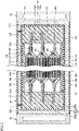
- Fig. 2 is a sectional view taken along the line II-II in Fig. 1 .
- a battery pack 1 is mounted on, for example, an electric-powered vehicle such as a battery electric vehicle.
- battery pack 1 includes a power storage device 10 and a cooling device 20.
- Cooling device 20 is a device that cools power storage device 10. Cooling device 20 is placed to be in contact with a lateral portion of power storage device 10. As shown in Fig. 1 , cooling device 20 is configured to allow a cooling medium (such as water) C to flow therein. Fig. 1 shows a state in which a part of cooling device 20 is missing.
- power storage device 10 includes a pair of external terminals 11, 12. External terminal 11 is a positive-electrode terminal, and external terminal 12 is a negative-electrode terminal. As shown in Fig. 2 , power storage device 10 includes a power storage module 100, a case 200, an insulating sheet 300, and a filling portion 400.
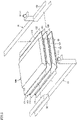
- Fig. 3 is an exploded perspective view schematically showing a configuration of a power storage module.
- power storage module 100 includes at least one power storage cell 101 and a plurality of bus bars 102.
- power storage module 100 includes a plurality of power storage cells 101.
- Power storage cells 101 are stacked in one direction (the vertical direction in Fig. 1 ).
- Figs. 2 and 3 show three power storage cells 101, the number of power storage cells 101 is not particularly limited.
- An example of power storage cell 101 is a lithium ion battery.
- Power storage cell 101 is a so-called laminate-type cell. Specifically, power storage cell 101 includes a plurality of electrode bodies 110, a current collector plate 120, a laminated film 130, an adhesive member 140, and an electrolyte solution (not shown). Power storage cell 101 may be formed of an all-solid-state battery having a solid electrolyte in place of a separator and an electrolyte solution.
- Electrode bodies 110 are stacked in one direction. Each of electrode bodies 110 includes a positive-electrode sheet 111, a negative-electrode sheet 112, and a separator 113 placed between positive-electrode sheet 111 and negative-electrode sheet 112. An end of positive-electrode sheet 111 and an end of negative-electrode sheet 112 are electrically connected to current collector plate 120.
- Current collector plate 120 includes a positive-electrode current collector plate 120p connected with each positive-electrode sheet 111, and a negative-electrode current collector plate 120n connected with each negative-electrode sheet 112.
- Positive-electrode current collector plate 120p is placed on one side of each sheet 111, 112 in an orthogonal direction orthogonal to a direction of stacking of positive-electrode sheets 111 and negative-electrode sheets 112 (the one direction).
- positive-electrode current collector plate 120p is shaped into a flat plate.
- Positive-electrode current collector plate 120p is made of, for example, aluminum.
- Positive-electrode current collector plate 120p includes a positive-electrode protrusion 121 shaped to protrude from laminated film 130 toward one side in the orthogonal direction.
- Negative-electrode current collector plate 120n is placed on the other side of each sheet 111, 112 in the orthogonal direction.
- negative-electrode current collector plate 120n is shaped into a flat plate.
- Negative-electrode current collector plate 120n is made of, for example, copper.
- Negative-electrode current collector plate 120n includes a negative-electrode protrusion 122 shaped to protrude from laminated film 130 toward the other side in the orthogonal direction. Negative-electrode current collector plate 120n may be placed on the same side as the side on which positive-electrode current collector plate 120p is placed.
- negative-electrode current collector plate 120n is placed at a position at which negative-electrode current collector plate 120n is adjacent to positive-electrode current collector plate 120p in a direction orthogonal to both of the one direction and the orthogonal direction.
- power storage cells 101 are stacked such that positive-electrode protrusion 121 in one power storage cell 101 and negative-electrode protrusion 122 in power storage cell 101 adjacent to the one power storage cell 101 face each other in the one direction.
- positive-electrode protrusion 121 of power storage cell 101 placed at an end on one side in a direction is connected with a bus bar 13 provided with external terminal 11
- negative-electrode protrusion 122 of power storage cell 101 placed at an end on the other side in the direction is connected with a bus bar 14 provided with external terminal 12.
- Laminated film 130 covers electrode bodies 110 and a part of current collector plate 120. More specifically, laminated film 130 covers positive-electrode sheets 111, negative-electrode sheets 112, separators 113, a part of positive-electrode current collector plate 120p, and a part of negative-electrode current collector plate 120n. Laminated film 130 is filled with an electrolyte solution (not shown).
- Adhesive member 140 is a member that bonds laminated film 130 to each current collector plate 120p, 120n.
- Adhesive member 140 is made of an insulating material (such as a resin).
- Adhesive member 140 is shaped to protrude from laminated film 130. Specially, adhesive member 140 covers a part of positive-electrode protrusion 121 and a part of negative-electrode protrusion 122.
- Bus bar 102 connects positive-electrode protrusion 121 and negative-electrode protrusion 122 that face each other such that power storage cells 101 are electrically connected in series.
- Bus bar 102 includes a positive-electrode contact portion 102a, a negative-electrode contact portion 102b, and a coupling portion 102c.
- Positive-electrode contact portion 102a is shaped into a flat plate. Positive-electrode contact portion 102a is in surface contact with positive-electrode protrusion 121. Positive-electrode contact portion 102a is welded to positive-electrode protrusion 121.
- Negative-electrode contact portion 102b is shaped into a flat plate. Negative-electrode contact portion 102b is in surface contact with negative-electrode protrusion 122. Negative-electrode contact portion 102b is welded to negative-electrode protrusion 122.
- Coupling portion 102c couples positive-electrode contact portion 102a to negative-electrode contact portion 102b.
- Coupling portion 102c is shaped to extend in one direction (a direction in which positive-electrode protrusion 121 and negative-electrode protrusion 122 face each other).
- coupling portion 102c couples an inner end of positive-electrode contact portion 102a in the orthogonal direction to an inner end of negative-electrode contact portion 102b in the orthogonal direction.
- bus bar 102 is shaped to have an opening that opens outward in the orthogonal direction.
- Case 200 houses power storage module 100.
- Case 200 is made of a metal (such as aluminum).
- Case 200 includes a case body 210 and a closing plate 220, as shown in Fig. 1 .
- Case body 210 has an opening that opens in at least one direction.
- case body 210 is shaped into a square tube having a central axis extending in a direction orthogonal to a direction of stacking of power storage cells 101.
- Case body 210 is provided with an inlet h (see Fig. 2 ).
- Closing plate 220 is welded to case body 210 so as to close the opening of case body 210. Closing plate 220 is shaped into a flat plate.
- Cooling device 20 is provided to be in contact with an outer lateral surface of case body 210. In other words, cooling device 20 is provided to be in contact with case 200 in the direction orthogonal to the direction of stacking of power storage cells 101.
- Insulating sheet 300 covers an inner surface of case body 210 and an inner surface of closing plate 220. Insulating sheet 300 may cover an upper surface and a lower surface of case body 210, as shown in Fig. 2 .
- Filling portion 400 is made of an insulating material.
- filling portion 400 is made of a thermally conductive material.
- Filling portion 400 is formed by injecting the material (in the present embodiment, a potting material) into case 200 through inlet h of case 200.
- Filling portion 400 covers the tip of positive-electrode protrusion 121 and the tip of negative-electrode protrusion 122, as shown in Fig. 2 . Filling portion 400 entirely covers protrusion 121, 122 together with adhesive member 140. Filling portion 400 may cover adhesive material 140 and an end of laminated film 130.
- filling portion 400 entirely covers bus bars 102, 13, 14.
- filling portion 400 is in contact with insulating sheet 300 provided on the inner surface of case body 210 and insulating sheet 300 provided on the inner surface of closing plate 220. As a result, a relative displacement of power storage module 100 to case 200 is reduced.
- Power storage device 10 may further include a restriction unit 500, as shown in Fig. 2 .
- Restriction unit 500 is placed between power storage module 100 and case body 210. Restriction unit 500 may be placed between a pair of power storage cells 101 adjacent to each other.
- Restriction unit 500 restricts a relative displacement of power storage module 100 to case 200 in the direction of stacking of power storage cells 101.
- Restriction unit 500 is made of, for example, a material having dilatency characteristics. Specifically, when each power storage cell 101 is displaced relative to case 200 at a low velocity in the direction of stacking, such as when each power storage cell 101 expands, restriction unit 500 elastically deforms to absorb the expansion of each power storage cell 101. On the other hand, when each power storage cell 101 is displaced relative to case 200 at a relatively high velocity in the direction of stacking, such as when power storage device 10 vibrates, restriction unit 500 shows a relatively high modulus of elasticity to restrict a relative displacement of each power storage cell 101 to case 200. This reduces resonance of power storage module 100 when power storage device 10 vibrates.
- bus bar 102 is shaped to extend in one direction as describe above, the length of bus bar 102 in the one direction can be adjusted, thus accommodating changes in the length between positive-electrode protrusion 121 and negative-electrode protrusion 122 due to a change in the thickness of each power storage cell 101 in the direction of stacking. Consequently, a change in the thickness of each power storage cell 101 can be accommodated while providing commonality of shape between positive-electrode current collector plate 120p and negative-electrode current collector plate 120n.
- current collector plate 120 and bus bar 102 are cooled by cooling device 20 via filling portion 400 made of a thermally conductive material from the lateral portion of case 200 in the direction orthogonal to the direction of stacking.
- Current collector plate 120 and bus bar 102 are made of metal, and accordingly, power storage module 100 is cooled effectively.
- Fig. 4 is a sectional view schematically showing a configuration of a battery pack including a power storage device of Embodiment 2 of the present disclosure.
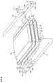
- Fig. 5 is an exploded perspective view schematically showing a configuration of a power storage module in the power storage device of Embodiment 2 of the present disclosure.
- Embodiment 2 will describe only a difference from Embodiment 1, and will not repeat the description on the same structure, and function and effect as those of Embodiment 1.
- coupling portion 102c couples an outer end of positive-electrode contact portion 102a in the orthogonal direction to an outer end of negative-electrode contact portion 102b in the orthogonal direction.
- bus bar 102 is shaped to have an opening that opens inward in the orthogonal direction.
- positive-electrode contact portion 102a may be welded to any surface of positive-electrode protrusion 121
- negative-electrode contact portion 102b may be welded to any surface of negative-electrode protrusion 122.
- coupling portion 102c of bus bar 102 is provided with a through-hole 102h.
- positive-electrode contact portion 102a can be welded to positive-electrode protrusion 121 and negative-electrode contact portion 102b can be welded to negative-electrode protrusion 122, from outside of power storage module 100 in the orthogonal direction.
- FIG. 6 is a sectional view schematically showing a configuration of a battery pack including a power storage device of Embodiment 3 of the present disclosure.
- Embodiment 3 will describe only a difference from Embodiment 1, and will not repeat the description on the same structure, and function and effect as those of Embodiment 1.
- positive-electrode protrusion 121 includes a positive-electrode projection 121a and a positive-electrode bent portion 121b
- negative-electrode protrusion 122 includes a negative-electrode projection 122a and a negative-electrode bent portion 122b.
- Positive-electrode projection 121a is shaped to project toward one side in the orthogonal direction. Positive-electrode projection 121a is shaped into a flat plate.
- Positive-electrode bent portion 121b is shaped to extend from an outer end of positive-electrode projection 121a in the orthogonal direction toward one side in the one direction. Positive-electrode bent portion 121b is shaped into a flat plate. Positive-electrode bent portion 121b is orthogonal to positive-electrode projection 121a.
- Negative-electrode projection 122a is shaped to project to the other side in the orthogonal direction. Negative-electrode projection 122a is shaped into a flat plate.
- Negative-electrode bent portion 122b is shaped to extend from an outer end of negative-electrode projection 122a in the orthogonal direction toward the other side in the one direction. In other words, negative-electrode bent portion 122b extends from negative-electrode projection 122a in the direction opposite to the direction in which positive-electrode bent portion 121b extends from positive-electrode projection 121a.
- negative-electrode bent portion 122b in one power storage cell 101 faces, in the one direction, positive-electrode bent portion 121b in a power storage cell 101 adjacent to the one power storage cell 101.
- Negative-electrode bent portion 122b is shaped into a flat plate. Negative-electrode bent portion 122b is orthogonal to negative-electrode projection 122a.
- Bus bar 102 is shaped into a flat plate.
- Bus bar 102 connects positive-electrode bent portion 121b to negative-electrode bent portion 122b with being in surface contact with both of positive-electrode bent portion 121b and negative-electrode bent portion 122b.
- Bus bar 102 is in contact with the inner lateral surface of each bent portion121b, 122b in the orthogonal direction.
- Bus bar 102 is welded to positive-electrode bent portion 121b and negative-electrode bent portion 122b.
- bus bar 102 may be in contact with the outer lateral surface of each bent portion 121b, 122b in the orthogonal direction.
- a power storage device in the embodiment described above includes a plurality of power storage cells stacked in one direction, and a bus bar that electrically connects power storage cells of the plurality of power storage cells to each other.
- Each of the power storage cells includes a plurality of positive-electrode sheets stacked in the one direction, a plurality of negative-electrode sheets stacked in the one direction, a positive-electrode current collector plate connected to the plurality of positive-electrode sheets, a negative-electrode current collector plate connected to the plurality of negative-electrode sheets, and a laminated film covering the plurality of positive-electrode sheets, the plurality of negative-electrode sheets, a part of the positive-electrode current collector plate, and a part of the negative-electrode current collector plate.
- the positive-electrode current collector plate includes a positive-electrode protrusion shaped to protrude from the laminated film in an orthogonal direction orthogonal to the one direction.
- the negative-electrode current collector plate includes a negative-electrode protrusion shaped to protrude from the laminated film in the orthogonal direction.
- the plurality of power storage cells are stacked such that the positive-electrode protrusion in one power storage cell among the plurality of power storage cells and the negative-electrode protrusion in another power storage cell adjacent to the one power storage cell among the plurality of power storage cells face each other in the one direction.
- the bus bar is shaped to extend in the one direction and connects the positive-electrode protrusion to the negative-electrode protrusion.
- the bus bar since the bus bar is shaped to extend in one direction, the length of the bus bar in the one direction can be adjusted, thus accommodating changes in the length between the positive-electrode protrusion and the negative-electrode protrusion due to the change in the thickness of each power storage cell in the direction of stacking.
- the change in the thickness of each power storage cell can be accommodated while providing commonality of shape among the positive-electrode current collector plate and the negative-electrode current collector plate.
- the positive-electrode protrusion and the negative-electrode protrusion may be each shaped into a flat plate orthogonal to the one direction.
- the bus bar may include a positive-electrode contact portion that is in surface contact with the positive-electrode protrusion, a negative-electrode contact portion that is in surface contact with the negative-electrode protrusion, and a coupling portion shaped to extend in the one direction and coupling the positive-electrode contact portion to the negative-electrode contact portion.
- the coupling portion may couple an inner end of the positive-electrode contact portion in the orthogonal direction to an inner end of the negative-electrode contact portion in the orthogonal direction.
- the positive-electrode protrusion may include a positive-electrode projection projecting in the orthogonal direction, and a positive-electrode bent portion shaped to extend from an outer end of the positive-electrode projection in the orthogonal direction toward one side in the one direction.
- the negative-electrode protrusion may include a negative-electrode projection projecting in the orthogonal direction, and a negative-electrode bent portion shaped to extend from an outer end of the negative-electrode projection in the orthogonal direction toward an another side in the one direction.
- the bus bar may be shaped into a flat plate and connect the positive-electrode bent portion to the negative-electrode bent portion while being in surface contact with both of the positive-electrode bent portion and the negative-electrode bent portion.
Landscapes
- Chemical & Material Sciences (AREA)
- Chemical Kinetics & Catalysis (AREA)
- Electrochemistry (AREA)
- General Chemical & Material Sciences (AREA)
- Engineering & Computer Science (AREA)
- Manufacturing & Machinery (AREA)
- Materials Engineering (AREA)
- Aviation & Aerospace Engineering (AREA)
- Connection Of Batteries Or Terminals (AREA)
- Battery Mounting, Suspending (AREA)
- Secondary Cells (AREA)
Abstract
Description
- This nonprovisional application is based on
Japanese Patent Application No. 2021-060593 filed on March 31, 2021 - The present disclosure relates to a power storage device.
- A power storage device including a plurality of power storage cells has conventionally been known. For example,
Japanese Patent Laying-Open No. 2005- 190885 - In the laminated battery module disclosed in
Japanese Patent Laying-Open No. 2005-190885 - An object of the present disclosure is to provide a power storage device that can accommodate changes in the thickness of each power storage cell while providing commonality of shape among current collector plates.
- A power storage device according to an aspect of the present disclosure includes a plurality of power storage cells stacked in one direction, and a bus bar that electrically connects power storage cells of the plurality of power storage cells to each other. Each of the power storage cells includes a plurality of positive-electrode sheets stacked in the one direction, a plurality of negative-electrode sheets stacked in the one direction, a positive-electrode current collector plate connected to the plurality of positive-electrode sheets, a negative-electrode current collector plate connected to the plurality of negative-electrode sheets, and a laminated film covering the plurality of positive-electrode sheets, the plurality of negative-electrode sheets, a part of the positive-electrode current collector plate, and a part of the negative-electrode current collector plate. The positive-electrode current collector plate includes a positive-electrode protrusion shaped to protrude from the laminated film in an orthogonal direction orthogonal to the one direction. The negative-electrode current collector plate includes a negative-electrode protrusion shaped to protrude from the laminated film in the orthogonal direction. The plurality of power storage cells are stacked such that the positive-electrode protrusion in one power storage cell among the plurality of power storage cells and the negative-electrode protrusion in another power storage cell adjacent to the one power storage cell among the plurality of power storage cells face each other in the one direction. The bus bar is shaped to extend in the one direction and connects the positive-electrode protrusion to the negative-electrode protrusion.
- The foregoing and other objects, features, aspects and advantages of the present disclosure will become more apparent from the following detailed description of the present disclosure when taken in conjunction with the accompanying drawings.
-
-
Fig. 1 is a perspective view schematically showing a configuration of a battery pack including a power storage device of Embodiment 1 of the present disclosure. -
Fig. 2 is a sectional view taken along the line II-II inFig. 1 . -
Fig. 3 is an exploded perspective view schematically showing a configuration of a power storage module. -
Fig. 4 is a sectional view schematically showing a configuration of a battery pack including a power storage device of Embodiment 2 of the present disclosure. -
Fig. 5 is an exploded perspective view schematically showing a configuration of a power storage module in the power storage device of Embodiment 2 of the present disclosure. -
Fig. 6 is a sectional view schematically showing a configuration of a battery pack including a power storage device of Embodiment 3 of the present disclosure. - Embodiments of the present disclosure will be described with reference to the drawings. The same or corresponding elements in the drawings have the same reference characters allotted in the figures referenced below.
-
Fig. 1 is a perspective view schematically showing a configuration of a battery pack including a power storage device of Embodiment 1 of the present disclosure.Fig. 2 is a sectional view taken along the line II-II inFig. 1 . A battery pack 1 is mounted on, for example, an electric-powered vehicle such as a battery electric vehicle. - As shown in
Figs. 1 and2 , battery pack 1 includes apower storage device 10 and acooling device 20.Cooling device 20 is a device that coolspower storage device 10.Cooling device 20 is placed to be in contact with a lateral portion ofpower storage device 10. As shown inFig. 1 ,cooling device 20 is configured to allow a cooling medium (such as water) C to flow therein.Fig. 1 shows a state in which a part of coolingdevice 20 is missing. - As shown in
Fig. 1 ,power storage device 10 includes a pair ofexternal terminals External terminal 11 is a positive-electrode terminal, andexternal terminal 12 is a negative-electrode terminal. As shown inFig. 2 ,power storage device 10 includes apower storage module 100, acase 200, an insulatingsheet 300, and a fillingportion 400. -
Fig. 3 is an exploded perspective view schematically showing a configuration of a power storage module. As shown inFigs. 2 and3 ,power storage module 100 includes at least onepower storage cell 101 and a plurality of bus bars 102. - In the present embodiment,
power storage module 100 includes a plurality ofpower storage cells 101.Power storage cells 101 are stacked in one direction (the vertical direction inFig. 1 ). AlthoughFigs. 2 and3 show threepower storage cells 101, the number ofpower storage cells 101 is not particularly limited. An example ofpower storage cell 101 is a lithium ion battery. -
Power storage cell 101 is a so-called laminate-type cell. Specifically,power storage cell 101 includes a plurality ofelectrode bodies 110, acurrent collector plate 120, alaminated film 130, anadhesive member 140, and an electrolyte solution (not shown).Power storage cell 101 may be formed of an all-solid-state battery having a solid electrolyte in place of a separator and an electrolyte solution. -
Electrode bodies 110 are stacked in one direction. Each ofelectrode bodies 110 includes a positive-electrode sheet 111, a negative-electrode sheet 112, and aseparator 113 placed between positive-electrode sheet 111 and negative-electrode sheet 112. An end of positive-electrode sheet 111 and an end of negative-electrode sheet 112 are electrically connected tocurrent collector plate 120. -
Current collector plate 120 includes a positive-electrodecurrent collector plate 120p connected with each positive-electrode sheet 111, and a negative-electrodecurrent collector plate 120n connected with each negative-electrode sheet 112. - Positive-electrode
current collector plate 120p is placed on one side of eachsheet electrode sheets 111 and negative-electrode sheets 112 (the one direction). In the present embodiment, positive-electrodecurrent collector plate 120p is shaped into a flat plate. Positive-electrodecurrent collector plate 120p is made of, for example, aluminum. Positive-electrodecurrent collector plate 120p includes a positive-electrode protrusion 121 shaped to protrude fromlaminated film 130 toward one side in the orthogonal direction. - Negative-electrode
current collector plate 120n is placed on the other side of eachsheet current collector plate 120n is shaped into a flat plate. Negative-electrodecurrent collector plate 120n is made of, for example, copper. Negative-electrodecurrent collector plate 120n includes a negative-electrode protrusion 122 shaped to protrude fromlaminated film 130 toward the other side in the orthogonal direction. Negative-electrodecurrent collector plate 120n may be placed on the same side as the side on which positive-electrodecurrent collector plate 120p is placed. In this case, negative-electrodecurrent collector plate 120n is placed at a position at which negative-electrodecurrent collector plate 120n is adjacent to positive-electrodecurrent collector plate 120p in a direction orthogonal to both of the one direction and the orthogonal direction. - As shown in
Fig. 2 ,power storage cells 101 are stacked such that positive-electrode protrusion 121 in onepower storage cell 101 and negative-electrode protrusion 122 inpower storage cell 101 adjacent to the onepower storage cell 101 face each other in the one direction. - As shown in
Fig. 3 , positive-electrode protrusion 121 ofpower storage cell 101 placed at an end on one side in a direction is connected with abus bar 13 provided withexternal terminal 11, and negative-electrode protrusion 122 ofpower storage cell 101 placed at an end on the other side in the direction is connected with abus bar 14 provided withexternal terminal 12. -
Laminated film 130 coverselectrode bodies 110 and a part ofcurrent collector plate 120. More specifically,laminated film 130 covers positive-electrode sheets 111, negative-electrode sheets 112,separators 113, a part of positive-electrodecurrent collector plate 120p, and a part of negative-electrodecurrent collector plate 120n.Laminated film 130 is filled with an electrolyte solution (not shown). -
Adhesive member 140 is a member that bondslaminated film 130 to eachcurrent collector plate Adhesive member 140 is made of an insulating material (such as a resin).Adhesive member 140 is shaped to protrude fromlaminated film 130. Specially,adhesive member 140 covers a part of positive-electrode protrusion 121 and a part of negative-electrode protrusion 122. -
Bus bar 102 connects positive-electrode protrusion 121 and negative-electrode protrusion 122 that face each other such thatpower storage cells 101 are electrically connected in series.Bus bar 102 includes a positive-electrode contact portion 102a, a negative-electrode contact portion 102b, and acoupling portion 102c. - Positive-
electrode contact portion 102a is shaped into a flat plate. Positive-electrode contact portion 102a is in surface contact with positive-electrode protrusion 121. Positive-electrode contact portion 102a is welded to positive-electrode protrusion 121. - Negative-
electrode contact portion 102b is shaped into a flat plate. Negative-electrode contact portion 102b is in surface contact with negative-electrode protrusion 122. Negative-electrode contact portion 102b is welded to negative-electrode protrusion 122. - Coupling
portion 102c couples positive-electrode contact portion 102a to negative-electrode contact portion 102b. Couplingportion 102c is shaped to extend in one direction (a direction in which positive-electrode protrusion 121 and negative-electrode protrusion 122 face each other). In the present embodiment,coupling portion 102c couples an inner end of positive-electrode contact portion 102a in the orthogonal direction to an inner end of negative-electrode contact portion 102b in the orthogonal direction. In other words,bus bar 102 is shaped to have an opening that opens outward in the orthogonal direction. This facilitates welding of positive-electrode contact portion 102a to positive-electrode protrusion 121 and welding of negative-electrode contact portion 102b to negative-electrode protrusion 122, from outside ofpower storage module 100 in the orthogonal direction. -
Case 200 housespower storage module 100.Case 200 is made of a metal (such as aluminum).Case 200 includes acase body 210 and aclosing plate 220, as shown inFig. 1 . -
Case body 210 has an opening that opens in at least one direction. In the present embodiment,case body 210 is shaped into a square tube having a central axis extending in a direction orthogonal to a direction of stacking ofpower storage cells 101.Case body 210 is provided with an inlet h (seeFig. 2 ). -
Closing plate 220 is welded tocase body 210 so as to close the opening ofcase body 210.Closing plate 220 is shaped into a flat plate. -
Cooling device 20 is provided to be in contact with an outer lateral surface ofcase body 210. In other words, coolingdevice 20 is provided to be in contact withcase 200 in the direction orthogonal to the direction of stacking ofpower storage cells 101. - Insulating
sheet 300 covers an inner surface ofcase body 210 and an inner surface of closingplate 220. Insulatingsheet 300 may cover an upper surface and a lower surface ofcase body 210, as shown inFig. 2 . - Filling
portion 400 is made of an insulating material. Preferably, fillingportion 400 is made of a thermally conductive material. Fillingportion 400 is formed by injecting the material (in the present embodiment, a potting material) intocase 200 through inlet h ofcase 200. - Filling
portion 400 covers the tip of positive-electrode protrusion 121 and the tip of negative-electrode protrusion 122, as shown inFig. 2 . Fillingportion 400 entirely coversprotrusion adhesive member 140. Fillingportion 400 may coveradhesive material 140 and an end oflaminated film 130. - Preferably, filling
portion 400 entirely coversbus bars portion 400 is in contact with insulatingsheet 300 provided on the inner surface ofcase body 210 and insulatingsheet 300 provided on the inner surface of closingplate 220. As a result, a relative displacement ofpower storage module 100 tocase 200 is reduced. -
Power storage device 10 may further include arestriction unit 500, as shown inFig. 2 .Restriction unit 500 is placed betweenpower storage module 100 andcase body 210.Restriction unit 500 may be placed between a pair ofpower storage cells 101 adjacent to each other. -
Restriction unit 500 restricts a relative displacement ofpower storage module 100 tocase 200 in the direction of stacking ofpower storage cells 101.Restriction unit 500 is made of, for example, a material having dilatency characteristics. Specifically, when eachpower storage cell 101 is displaced relative tocase 200 at a low velocity in the direction of stacking, such as when eachpower storage cell 101 expands,restriction unit 500 elastically deforms to absorb the expansion of eachpower storage cell 101. On the other hand, when eachpower storage cell 101 is displaced relative tocase 200 at a relatively high velocity in the direction of stacking, such as whenpower storage device 10 vibrates,restriction unit 500 shows a relatively high modulus of elasticity to restrict a relative displacement of eachpower storage cell 101 tocase 200. This reduces resonance ofpower storage module 100 whenpower storage device 10 vibrates. - In
power storage device 10 of the present embodiment, sincebus bar 102 is shaped to extend in one direction as describe above, the length ofbus bar 102 in the one direction can be adjusted, thus accommodating changes in the length between positive-electrode protrusion 121 and negative-electrode protrusion 122 due to a change in the thickness of eachpower storage cell 101 in the direction of stacking. Consequently, a change in the thickness of eachpower storage cell 101 can be accommodated while providing commonality of shape between positive-electrodecurrent collector plate 120p and negative-electrodecurrent collector plate 120n. - In the present embodiment,
current collector plate 120 andbus bar 102 are cooled by coolingdevice 20 via fillingportion 400 made of a thermally conductive material from the lateral portion ofcase 200 in the direction orthogonal to the direction of stacking.Current collector plate 120 andbus bar 102 are made of metal, and accordingly,power storage module 100 is cooled effectively. - Next,
power storage device 10 of Embodiment 2 of the present disclosure will be described with reference toFigs. 4 and5 .Fig. 4 is a sectional view schematically showing a configuration of a battery pack including a power storage device of Embodiment 2 of the present disclosure.Fig. 5 is an exploded perspective view schematically showing a configuration of a power storage module in the power storage device of Embodiment 2 of the present disclosure. Embodiment 2 will describe only a difference from Embodiment 1, and will not repeat the description on the same structure, and function and effect as those of Embodiment 1. - In the present embodiment,
coupling portion 102c couples an outer end of positive-electrode contact portion 102a in the orthogonal direction to an outer end of negative-electrode contact portion 102b in the orthogonal direction. In other words,bus bar 102 is shaped to have an opening that opens inward in the orthogonal direction. In the present embodiment, positive-electrode contact portion 102a may be welded to any surface of positive-electrode protrusion 121, and negative-electrode contact portion 102b may be welded to any surface of negative-electrode protrusion 122. - As shown in
Fig. 5 ,coupling portion 102c ofbus bar 102 is provided with a through-hole 102h. Through through-hole 102h, positive-electrode contact portion 102a can be welded to positive-electrode protrusion 121 and negative-electrode contact portion 102b can be welded to negative-electrode protrusion 122, from outside ofpower storage module 100 in the orthogonal direction. - In this manner, the position of
coupling portion 102c in the orthogonal direction is outside of that of Embodiment 1 in the orthogonal direction, leading to a smaller amount of the material (potting material) required for formation of fillingportion 400 that is in contact withcoupling portion 102c. As fillingportion 400 is in contact withcoupling portion 102c, a contact area between fillingportion 400 andbus bar 102 increases, thereby increasing the efficiency of cooling eachpower storage cell 101. -
Power storage device 10 of Embodiment 3 of the present disclosure will be described below with reference toFig. 6. Fig. 6 is a sectional view schematically showing a configuration of a battery pack including a power storage device of Embodiment 3 of the present disclosure. Embodiment 3 will describe only a difference from Embodiment 1, and will not repeat the description on the same structure, and function and effect as those of Embodiment 1. - In the present embodiment, positive-
electrode protrusion 121 includes a positive-electrode projection 121a and a positive-electrodebent portion 121b, and negative-electrode protrusion 122 includes a negative-electrode projection 122a and a negative-electrodebent portion 122b. - Positive-
electrode projection 121a is shaped to project toward one side in the orthogonal direction. Positive-electrode projection 121a is shaped into a flat plate. - Positive-electrode
bent portion 121b is shaped to extend from an outer end of positive-electrode projection 121a in the orthogonal direction toward one side in the one direction. Positive-electrodebent portion 121b is shaped into a flat plate. Positive-electrodebent portion 121b is orthogonal to positive-electrode projection 121a. - Negative-
electrode projection 122a is shaped to project to the other side in the orthogonal direction. Negative-electrode projection 122a is shaped into a flat plate. - Negative-electrode
bent portion 122b is shaped to extend from an outer end of negative-electrode projection 122a in the orthogonal direction toward the other side in the one direction. In other words, negative-electrodebent portion 122b extends from negative-electrode projection 122a in the direction opposite to the direction in which positive-electrodebent portion 121b extends from positive-electrode projection 121a. Thus, negative-electrodebent portion 122b in onepower storage cell 101 faces, in the one direction, positive-electrodebent portion 121b in apower storage cell 101 adjacent to the onepower storage cell 101. Negative-electrodebent portion 122b is shaped into a flat plate. Negative-electrodebent portion 122b is orthogonal to negative-electrode projection 122a. -
Bus bar 102 is shaped into a flat plate.Bus bar 102 connects positive-electrodebent portion 121b to negative-electrodebent portion 122b with being in surface contact with both of positive-electrodebent portion 121b and negative-electrodebent portion 122b.Bus bar 102 is in contact with the inner lateral surface of each bent portion121b, 122b in the orthogonal direction.Bus bar 102 is welded to positive-electrodebent portion 121b and negative-electrodebent portion 122b. - In Embodiment 3,
bus bar 102 may be in contact with the outer lateral surface of eachbent portion - It will be appreciated by a person skilled in the art that the exemplary embodiments described above provide specific examples of the following aspects.
- A power storage device in the embodiment described above includes a plurality of power storage cells stacked in one direction, and a bus bar that electrically connects power storage cells of the plurality of power storage cells to each other. Each of the power storage cells includes a plurality of positive-electrode sheets stacked in the one direction, a plurality of negative-electrode sheets stacked in the one direction, a positive-electrode current collector plate connected to the plurality of positive-electrode sheets, a negative-electrode current collector plate connected to the plurality of negative-electrode sheets, and a laminated film covering the plurality of positive-electrode sheets, the plurality of negative-electrode sheets, a part of the positive-electrode current collector plate, and a part of the negative-electrode current collector plate. The positive-electrode current collector plate includes a positive-electrode protrusion shaped to protrude from the laminated film in an orthogonal direction orthogonal to the one direction. The negative-electrode current collector plate includes a negative-electrode protrusion shaped to protrude from the laminated film in the orthogonal direction. The plurality of power storage cells are stacked such that the positive-electrode protrusion in one power storage cell among the plurality of power storage cells and the negative-electrode protrusion in another power storage cell adjacent to the one power storage cell among the plurality of power storage cells face each other in the one direction. The bus bar is shaped to extend in the one direction and connects the positive-electrode protrusion to the negative-electrode protrusion.
- In this power storage device, since the bus bar is shaped to extend in one direction, the length of the bus bar in the one direction can be adjusted, thus accommodating changes in the length between the positive-electrode protrusion and the negative-electrode protrusion due to the change in the thickness of each power storage cell in the direction of stacking. Thus, the change in the thickness of each power storage cell can be accommodated while providing commonality of shape among the positive-electrode current collector plate and the negative-electrode current collector plate.
- The positive-electrode protrusion and the negative-electrode protrusion may be each shaped into a flat plate orthogonal to the one direction. The bus bar may include a positive-electrode contact portion that is in surface contact with the positive-electrode protrusion, a negative-electrode contact portion that is in surface contact with the negative-electrode protrusion, and a coupling portion shaped to extend in the one direction and coupling the positive-electrode contact portion to the negative-electrode contact portion.
- In this case, the coupling portion may couple an inner end of the positive-electrode contact portion in the orthogonal direction to an inner end of the negative-electrode contact portion in the orthogonal direction.
- The positive-electrode protrusion may include a positive-electrode projection projecting in the orthogonal direction, and a positive-electrode bent portion shaped to extend from an outer end of the positive-electrode projection in the orthogonal direction toward one side in the one direction. The negative-electrode protrusion may include a negative-electrode projection projecting in the orthogonal direction, and a negative-electrode bent portion shaped to extend from an outer end of the negative-electrode projection in the orthogonal direction toward an another side in the one direction. The bus bar may be shaped into a flat plate and connect the positive-electrode bent portion to the negative-electrode bent portion while being in surface contact with both of the positive-electrode bent portion and the negative-electrode bent portion.
- Although the present disclosure has been described and illustrated in detail, it is clearly understood that the same is by way of illustration and example only and is not to be taken by way of limitation, the scope of the present disclosure being interpreted by the terms of the appended claims.
Claims (4)
- A power storage device (10) comprising:a plurality of power storage cells (101) stacked in one direction; anda bus bar (102) that electrically connects power storage cells of the plurality of power storage cells to each other, whereineach of the power storage cells (101) includesa plurality of positive-electrode sheets (111) stacked in the one direction,a plurality of negative-electrode sheets (112) stacked in the one direction,a positive-electrode current collector plate (120p) connected to the plurality of positive-electrode sheets,a negative-electrode current collector plate (120n) connected to the plurality of negative-electrode sheets, anda laminated film (130) covering the plurality of positive-electrode sheets, the plurality of negative-electrode sheets, a part of the positive-electrode current collector plate, and a part of the negative-electrode current collector plate,the positive-electrode current collector plate (120p) includes a positive-electrode protrusion (121) shaped to protrude from the laminated film in an orthogonal direction orthogonal to the one direction,the negative-electrode current collector plate (120n) includes a negative-electrode protrusion (122) shaped to protrude from the laminated film in the orthogonal direction,the plurality of power storage cells (101) are stacked such that the positive-electrode protrusion (121) in one power storage cell among the plurality of power storage cells and the negative-electrode protrusion (122) in another power storage cell adjacent to the one power storage cell among the plurality of power storage cells face each other in the one direction, andthe bus bar (102) is shaped to extend in the one direction and connects the positive-electrode protrusion (121) to the negative-electrode protrusion (122).
- The power storage device according to claim 1, whereinthe positive-electrode protrusion (121) and the negative-electrode protrusion (122) are each shaped into a flat plate orthogonal to the one direction, andthe bus bar (102) includesa positive-electrode contact portion (102a) that is in surface contact with the positive-electrode protrusion,a negative-electrode contact portion (102b) that is in surface contact with the negative-electrode protrusion, anda coupling portion (102c) shaped to extend in the one direction and coupling the positive-electrode contact portion (102a) to the negative-electrode contact portion (102b).
- The power storage device according to claim 2, wherein the coupling portion (102c) couples an inner end of the positive-electrode contact portion (102a) in the orthogonal direction to an inner end of the negative-electrode contact portion (102b) in the orthogonal direction.
- The power storage device according to claim 1, whereinthe positive-electrode protrusion (121) includesa positive-electrode projection (121a) projecting in the orthogonal direction, anda positive-electrode bent portion (121b) shaped to extend from an outer end of the positive-electrode projection in the orthogonal direction toward one side in the one direction,the negative-electrode protrusion (122) includesa negative-electrode projection (122a) projecting in the orthogonal direction, anda negative-electrode bent portion (122b) shaped to extend from an outer end of the negative-electrode projection in the orthogonal direction toward an another side in the one direction, andthe bus bar (102) is shaped into a flat plate and connects the positive-electrode bent portion to the negative-electrode bent portion while being in surface contact with both of the positive-electrode bent portion (121b) and the negative-electrode bent portion (122b).
Applications Claiming Priority (1)
| Application Number | Priority Date | Filing Date | Title |
|---|---|---|---|
| JP2021060593A JP7380631B2 (en) | 2021-03-31 | 2021-03-31 | assembled battery |
Publications (3)
| Publication Number | Publication Date |
|---|---|
| EP4068457A1 true EP4068457A1 (en) | 2022-10-05 |
| EP4068457B1 EP4068457B1 (en) | 2026-01-21 |
| EP4068457C0 EP4068457C0 (en) | 2026-01-21 |
Family
ID=80446123
Family Applications (1)
| Application Number | Title | Priority Date | Filing Date |
|---|---|---|---|
| EP22157737.2A Active EP4068457B1 (en) | 2021-03-31 | 2022-02-21 | Power storage device |
Country Status (5)
| Country | Link |
|---|---|
| US (1) | US12412966B2 (en) |
| EP (1) | EP4068457B1 (en) |
| JP (1) | JP7380631B2 (en) |
| KR (1) | KR102783059B1 (en) |
| CN (1) | CN115149220B (en) |
Citations (4)
| Publication number | Priority date | Publication date | Assignee | Title |
|---|---|---|---|---|
| JP2005190885A (en) | 2003-12-26 | 2005-07-14 | Toyota Motor Corp | Laminated battery module and manufacturing method thereof |
| US20060257732A1 (en) * | 2001-09-04 | 2006-11-16 | Nec Corporation | Film packaged battery having a cupped portion |
| WO2007063877A1 (en) * | 2005-12-01 | 2007-06-07 | Nec Corporation | Method for producing electrical device assembly |
| JP2021060593A (en) | 2020-12-10 | 2021-04-15 | 株式会社Dnpファインケミカル | Pigment dispersion liquid for color filter, colored composition for color filter, color filter, and display device |
Family Cites Families (11)
| Publication number | Priority date | Publication date | Assignee | Title |
|---|---|---|---|---|
| KR20120023263A (en) | 2010-09-01 | 2012-03-13 | 에스케이이노베이션 주식회사 | Battery having cell tab connecting structure with resistance welding |
| CN104769746B (en) * | 2012-11-09 | 2017-10-03 | 日产自动车株式会社 | The manufacture method of battery pack and battery pack |
| WO2014171651A1 (en) * | 2013-04-19 | 2014-10-23 | (주)유진에너팜 | Apparatus for storing energy filled with heat transfer oils |
| KR101817236B1 (en) | 2014-12-24 | 2018-01-11 | 주식회사 엘지화학 | Method for welding of electrode-leads & secondary battery module utilizing thereof |
| JP6264663B2 (en) * | 2015-04-03 | 2018-01-24 | トヨタ自動車株式会社 | battery |
| JP2018049823A (en) * | 2016-09-14 | 2018-03-29 | 旭化成株式会社 | Power storage module having vibration-proof connection structure |
| JP6593304B2 (en) * | 2016-11-07 | 2019-10-23 | トヨタ自動車株式会社 | Electric storage device and method for manufacturing electric storage device |
| US10673028B2 (en) * | 2017-09-28 | 2020-06-02 | Maxwell Holdings, Ltd. | Electrochemical element |
| JP6988393B2 (en) * | 2017-11-13 | 2022-01-05 | トヨタ自動車株式会社 | Battery module and battery pack |
| JP7049874B2 (en) * | 2018-03-22 | 2022-04-07 | 河村電器産業株式会社 | How to assemble a power storage device |
| KR102450418B1 (en) | 2018-12-07 | 2022-09-30 | 주식회사 엘지에너지솔루션 | Battery module with improved safety, battery pack comprising the battery module and vehicle comprising the same |
-
2021
- 2021-03-31 JP JP2021060593A patent/JP7380631B2/en active Active
-
2022
- 2022-02-21 EP EP22157737.2A patent/EP4068457B1/en active Active
- 2022-03-07 US US17/688,038 patent/US12412966B2/en active Active
- 2022-03-11 KR KR1020220030652A patent/KR102783059B1/en active Active
- 2022-03-28 CN CN202210314098.2A patent/CN115149220B/en active Active
Patent Citations (4)
| Publication number | Priority date | Publication date | Assignee | Title |
|---|---|---|---|---|
| US20060257732A1 (en) * | 2001-09-04 | 2006-11-16 | Nec Corporation | Film packaged battery having a cupped portion |
| JP2005190885A (en) | 2003-12-26 | 2005-07-14 | Toyota Motor Corp | Laminated battery module and manufacturing method thereof |
| WO2007063877A1 (en) * | 2005-12-01 | 2007-06-07 | Nec Corporation | Method for producing electrical device assembly |
| JP2021060593A (en) | 2020-12-10 | 2021-04-15 | 株式会社Dnpファインケミカル | Pigment dispersion liquid for color filter, colored composition for color filter, color filter, and display device |
Also Published As
| Publication number | Publication date |
|---|---|
| JP7380631B2 (en) | 2023-11-15 |
| CN115149220B (en) | 2024-04-30 |
| US20220320693A1 (en) | 2022-10-06 |
| EP4068457B1 (en) | 2026-01-21 |
| US12412966B2 (en) | 2025-09-09 |
| KR102783059B1 (en) | 2025-03-17 |
| CN115149220A (en) | 2022-10-04 |
| EP4068457C0 (en) | 2026-01-21 |
| JP2022156750A (en) | 2022-10-14 |
| KR20220136118A (en) | 2022-10-07 |
Similar Documents
| Publication | Publication Date | Title |
|---|---|---|
| KR102619201B1 (en) | Secondary Battery and Battery Module Having the Same | |
| KR100880389B1 (en) | Manufacturing Method of Secondary Battery Module | |
| KR101305218B1 (en) | Battery Module Having Fixing Member and Coupling Member, and Battery Pack Employed with the Same | |
| KR101326182B1 (en) | Battery Module Based upon Unit Module Having External Covering Member and Cartridge | |
| KR102937187B1 (en) | Battery Module and Battery Pack Having the Same and Vehicle | |
| JP2011159474A (en) | Battery pack | |
| US12308460B2 (en) | Battery, powered device, and method of manufacturing battery | |
| WO2025091752A1 (en) | Battery cell, battery, and electric device | |
| EP4024592A2 (en) | Battery module | |
| JP5344237B2 (en) | Assembled battery | |
| US12463278B2 (en) | Power storage device | |
| EP4068476A1 (en) | Power storage device | |
| EP4068457B1 (en) | Power storage device | |
| US20180145285A1 (en) | High-capacity stacked-electrode metal-ion accumulator capable of delivering high power | |
| EP4181296B1 (en) | Battery pack and device including the same | |
| CN222927717U (en) | Battery device and electricity utilization device | |
| EP4625683A1 (en) | Battery module and battery pack comprising same | |
| US12347880B2 (en) | Power storage device and method of manufacturing power storage device | |
| EP4708508A1 (en) | Battery pack and vehicle including same | |
| EP4621977A1 (en) | Battery module and battery pack comprising same | |
| KR20240012297A (en) | Battery pack and vehicle including the same | |
| KR20250139014A (en) | Battery cell and battyery module including the same | |
| KR20240110320A (en) | Battery cell comprising electrode lead and battery device comprising the same |
Legal Events
| Date | Code | Title | Description |
|---|---|---|---|
| PUAI | Public reference made under article 153(3) epc to a published international application that has entered the european phase |
Free format text: ORIGINAL CODE: 0009012 |
|
| STAA | Information on the status of an ep patent application or granted ep patent |
Free format text: STATUS: REQUEST FOR EXAMINATION WAS MADE |
|
| 17P | Request for examination filed |
Effective date: 20220221 |
|
| AK | Designated contracting states |
Kind code of ref document: A1 Designated state(s): AL AT BE BG CH CY CZ DE DK EE ES FI FR GB GR HR HU IE IS IT LI LT LU LV MC MK MT NL NO PL PT RO RS SE SI SK SM TR |
|
| RIC1 | Information provided on ipc code assigned before grant |
Ipc: H01M 10/0585 20100101AFI20250819BHEP Ipc: H01M 50/505 20210101ALI20250819BHEP Ipc: H01M 50/503 20210101ALI20250819BHEP Ipc: H01M 50/124 20210101ALI20250819BHEP Ipc: H01M 50/178 20210101ALI20250819BHEP Ipc: H01M 50/51 20210101ALI20250819BHEP Ipc: H01M 50/548 20210101ALI20250819BHEP Ipc: H01M 50/553 20210101ALI20250819BHEP |
|
| GRAP | Despatch of communication of intention to grant a patent |
Free format text: ORIGINAL CODE: EPIDOSNIGR1 |
|
| STAA | Information on the status of an ep patent application or granted ep patent |
Free format text: STATUS: GRANT OF PATENT IS INTENDED |
|
| INTG | Intention to grant announced |
Effective date: 20250926 |
|
| GRAS | Grant fee paid |
Free format text: ORIGINAL CODE: EPIDOSNIGR3 |
|
| GRAA | (expected) grant |
Free format text: ORIGINAL CODE: 0009210 |
|
| STAA | Information on the status of an ep patent application or granted ep patent |
Free format text: STATUS: THE PATENT HAS BEEN GRANTED |
|
| AK | Designated contracting states |
Kind code of ref document: B1 Designated state(s): AL AT BE BG CH CY CZ DE DK EE ES FI FR GB GR HR HU IE IS IT LI LT LU LV MC MK MT NL NO PL PT RO RS SE SI SK SM TR |
|
| REG | Reference to a national code |
Ref country code: CH Ref legal event code: F10 Free format text: ST27 STATUS EVENT CODE: U-0-0-F10-F00 (AS PROVIDED BY THE NATIONAL OFFICE) Effective date: 20260121 |
|
| REG | Reference to a national code |
Ref country code: DE Ref legal event code: R096 Ref document number: 602022028698 Country of ref document: DE |
|
| REG | Reference to a national code |
Ref country code: IE Ref legal event code: FG4D |
|
| U01 | Request for unitary effect filed |
Effective date: 20260206 |
|
| U07 | Unitary effect registered |
Designated state(s): AT BE BG DE DK EE FI FR IT LT LU LV MT NL PT RO SE SI Effective date: 20260212 |
|
| U20 | Renewal fee for the european patent with unitary effect paid |
Year of fee payment: 5 Effective date: 20260218 |
|
| PGFP | Annual fee paid to national office [announced via postgrant information from national office to epo] |
Ref country code: AT Payment date: 20260301 Year of fee payment: 5 |
|
| U1N | Appointed representative for the unitary patent procedure changed after the registration of the unitary effect |
Representative=s name: MARKS & CLERK LLP; GB |