EP4068316A1 - On-load tap changer - Google Patents
On-load tap changer Download PDFInfo
- Publication number
- EP4068316A1 EP4068316A1 EP19954055.0A EP19954055A EP4068316A1 EP 4068316 A1 EP4068316 A1 EP 4068316A1 EP 19954055 A EP19954055 A EP 19954055A EP 4068316 A1 EP4068316 A1 EP 4068316A1
- Authority
- EP
- European Patent Office
- Prior art keywords
- changeover switch
- oil tank
- receiving seat
- container
- tap changer
- Prior art date
- Legal status (The legal status is an assumption and is not a legal conclusion. Google has not performed a legal analysis and makes no representation as to the accuracy of the status listed.)
- Granted
Links
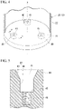
Images




Classifications
-
- H—ELECTRICITY
- H01—ELECTRIC ELEMENTS
- H01H—ELECTRIC SWITCHES; RELAYS; SELECTORS; EMERGENCY PROTECTIVE DEVICES
- H01H9/00—Details of switching devices, not covered by groups H01H1/00 - H01H7/00
- H01H9/0005—Tap change devices
- H01H9/0044—Casings; Mountings; Disposition in transformer housing
-
- H—ELECTRICITY
- H01—ELECTRIC ELEMENTS
- H01F—MAGNETS; INDUCTANCES; TRANSFORMERS; SELECTION OF MATERIALS FOR THEIR MAGNETIC PROPERTIES
- H01F29/00—Variable transformers or inductances not covered by group H01F21/00
- H01F29/02—Variable transformers or inductances not covered by group H01F21/00 with tappings on coil or winding; with provision for rearrangement or interconnection of windings
- H01F29/04—Variable transformers or inductances not covered by group H01F21/00 with tappings on coil or winding; with provision for rearrangement or interconnection of windings having provision for tap-changing without interrupting the load current
-
- H—ELECTRICITY
- H01—ELECTRIC ELEMENTS
- H01H—ELECTRIC SWITCHES; RELAYS; SELECTORS; EMERGENCY PROTECTIVE DEVICES
- H01H9/00—Details of switching devices, not covered by groups H01H1/00 - H01H7/00
- H01H9/0005—Tap change devices
- H01H2009/0061—Monitoring tap change switching devices
-
- H—ELECTRICITY
- H01—ELECTRIC ELEMENTS
- H01H—ELECTRIC SWITCHES; RELAYS; SELECTORS; EMERGENCY PROTECTIVE DEVICES
- H01H9/00—Details of switching devices, not covered by groups H01H1/00 - H01H7/00
- H01H9/0005—Tap change devices
- H01H9/0027—Operating mechanisms
Definitions
- Embodiments of the present invention relate to an on-load tap changer.
- An on-load tap changer is a device that changes over a tap during an operation (during load) of a transformer.
- the on-load tap changer includes a tap selector and a changeover switch.
- the tap selector selects a tap to operate in a transformer tap winding.
- the changeover switch changes over a circuit to the selected tap.
- the changeover switch is contained in an insulating container together with an insulating oil or gas.
- the changeover switch is mainly driven by a releasing force of a spring. A large force acts on the changeover switch to instantly change over the circuit. Therefore, it is required to firmly install the changeover switch.
- An object of the present invention is to provide an on-load tap changer in which a changeover switch can be firmly installed.
- An on-load tap changer includes a changeover switch and a container.
- the changeover switch performs a tap changeover operation in a winding.
- the container contains the changeover switch.
- the container has a bottom portion to which the changeover switch is fastened.
- Fig. 1 is a schematic view of a transformer according to a first embodiment.
- a transformer 1 includes a transformer main body (not shown), a tank 2 that contains the transformer main body together with an insulating oil, and an on-load tap changer 3 fixed to the tank 2.
- the transformer main body has an iron core and a winding mounted on the iron core.
- the tank 2 includes a top plate 5 extending in a horizontal direction. An opening portion 5a into which the on-load tap changer 3 is inserted from above is formed in the top plate 5.
- the on-load tap changer 3 closes the opening portion 5a of the top plate 5 in a state where a part of the on-load tap changer 3 is disposed in the tank 2.
- An electric operation mechanism (not shown) is disposed outside the tank 2 as a drive source that applies power to the on-load tap changer 3.
- the electric operation mechanism includes a motor. The electric operation mechanism rotates a relay shaft (not shown) connected to the on-load tap changer 3 and transmits power to the on-load tap changer 3.
- Fig. 2 is a perspective view showing a part of an on-load tap changer according to the first embodiment.
- the on-load tap changer 3 includes a tap selector 10, a changeover switch 11, and an oil tank 12.
- the tap selector 10 selects a tap in the winding of the transformer main body.
- the tap selector 10 is disposed in the tank 2.
- the changeover switch 11 instantly changes over a circuit to the selected tap as a tap changeover operation.
- the changeover switch 11 is disposed on the top plate 5 side with respect to the tap selector 10.
- the oil tank 12 contains the changeover switch 11 together with the insulating oil in the tank 2.
- the oil tank 12 blocks communication between the inside of the tank 2 and the inside of the oil tank 12.
- the oil tank 12 completely isolates the changeover switch 11 from the transformer main body.
- the oil tank 12 supports the tap selector 10 from above.
- Fig. 3 is a sectional view showing a part of an on-load tap changer according to the first embodiment.
- the oil tank 12 includes an oil tank main body 20 (a container), an oil tank lid 25, and a flange 27.
- the oil tank main body 20 includes a bottom wall portion 21 (a bottom portion) located at a lower end portion and a peripheral wall portion 22 extending upward from an outer peripheral portion of the bottom wall portion 21.
- the bottom wall portion 21 is disposed in the tank 2.
- the bottom wall portion 21 is disposed between the tap selector 10 and the changeover switch 11.
- the bottom wall portion 21 is formed in a circular shape when viewed from above.
- a transmission shaft 16 (a transmission portion) penetrates the bottom wall portion 21.
- the transmission shaft 16 extends in a vertical direction.
- the transmission shaft 16 is rotatably supported by the bottom wall portion 21.
- the transmission shaft 16 transmits power for operating the changeover switch 11 from the outside of the oil tank 12 to the inside of the oil tank 12 (details will be described later).
- the peripheral wall portion 22 is formed in a cylindrical shape as a whole.
- the peripheral wall portion 22 surrounds the changeover switch 11 from the outside in the horizontal direction.
- An oil tank opening portion 23 through which the changeover switch 11 can pass in the vertical direction is formed at an upper end portion of the oil tank main body 20.
- the oil tank opening portion 23 is open upward.
- Fig. 4 is a perspective view schematically showing the inside of an oil tank main body of the first embodiment.
- a receiving seat 40 is disposed on the bottom wall portion 21 of the oil tank main body 20.
- the receiving seat 40 supports the changeover switch 11 from below.
- the receiving seat 40 protrudes upward from an upper surface of the bottom wall portion 21.
- the receiving seat 40 may be integrally formed with the bottom wall portion 21, or may be formed as a separate member from the bottom wall portion 21 and joined to the bottom wall portion 21.
- a joining method between the bottom wall portion 21 and the receiving seat 40 may be metallurgical joining such as welding in which a joint portion has continuity, or may be mechanical joining such as fastening in which the joint portion has no continuity.
- Three or more receiving seats 40 are disposed to surround a central axis P of the peripheral wall portion 22 when viewed from above.
- the receiving seats 40 are disposed at equal angular intervals in a circumferential direction around the central axis P.
- a recess 41 that is recessed downward is formed in an upper surface of the receiving seat 40.
- Fig. 5 is a sectional view along a line V-V of Fig. 4 .
- the recess 41 includes a side surface 42 and a bottom surface 45.
- the side surface 42 extends downward from an upper end opening edge of the recess 41.
- the side surface 42 is formed in a circular shape in a cross section.
- the side surface 42 includes a tapered surface 43 facing the oil tank opening portion 23 side (upward) and a straight surface 44 extending uniformly in the vertical direction.
- the tapered surface 43 gradually reduces in diameter from the upper end opening edge of the recess 41 toward a downward side.
- the straight surface 44 extends downward from a lower end edge of the tapered surface 43 with a constant inner diameter.
- the bottom surface 45 extends inward in a radial direction (the horizontal direction) from a lower end edge of the straight surface 44.
- a female screw 46 extending downward is formed in the bottom surface 45.
- the female screw 46 is formed coaxially with the straight surface 44.
- a pipe 35 is disposed in the oil tank main body 20.
- the pipe 35 is fixedly disposed with respect to the oil tank main body 20.
- the pipe 35 extends in the vertical direction in the oil tank main body 20.
- a lower end portion of the pipe 35 is open near the bottom wall portion 21.
- the pipe 35 is used for sucking up the insulating oil in the oil tank main body 20.
- the oil tank lid 25 closes the oil tank opening portion 23.
- the oil tank lid 25 is disposed at an interval with respect to the changeover switch 11.
- the oil tank lid 25 is formed in a circular shape concentric with the oil tank main body 20 when viewed from above.
- the oil tank lid 25 is fastened to the upper end portion of the oil tank main body 20 from above.
- An outer peripheral portion of the oil tank lid 25 is in close contact with the upper end portion of the peripheral wall portion 22 of the oil tank main body 20 over the entire circumference.
- the flange 27 projects from an upper portion of the oil tank main body 20 and extends from the vicinity of the oil tank main body 20 over the entire circumference thereof.
- the flange 27 extends in the horizontal direction.
- the flange 27 is joined to the top plate 5 of the tank 2.
- the flange 27 is fastened to the top plate 5 from above.
- the flange 27 overlaps the entire inner peripheral edge of the opening portion 5a of the top plate 5 when viewed from above.
- the flange 27 is in close contact with the periphery of the opening portion 5a over the entire circumference in a state where the oil tank main body 20 is inserted into the opening portion 5a of the top plate 5 from above.
- the flange 27 closes a portion between the opening portion 5a of the top plate 5 and the oil tank main body 20.
- An outer peripheral edge of the flange 27 is formed to surround the entire tap selector 10 when viewed from above.
- the oil tank 12 is mainly formed by combining an oil tank main portion 31, an oil tank head portion 32, and a head portion lid 33 as parts.
- the oil tank main portion 31 includes a portion extending from an intermediate portion to a lower end portion of the oil tank main body 20 in the vertical direction.
- the entire oil tank main portion 31 is disposed in the tank 2.
- the oil tank main portion 31 is formed in a cylindrical shape that is open upward.
- the oil tank head portion 32 includes an upper portion of the oil tank main body 20 and the flange 27.
- the oil tank head portion 32 is formed in a cylindrical shape as a whole.
- a lower end portion of the oil tank head portion 32 is closely inserted inside an upper end portion of the oil tank main portion 31.
- the flange 27 is disposed at an intermediate portion of the oil tank head portion 32 in the vertical direction.
- the head portion lid 33 is the oil tank lid 25. The head portion lid 33 closes an opening at the upper end portion of the oil tank head portion 32 from above.
- Fig. 6 is a perspective view showing a changeover switch according to the first embodiment.
- the changeover switch 11 is fastened to the oil tank main body 20 with bolts 70 (male screws) disposed in the oil tank main body 20.
- the changeover switch 11 has an upper plate 50, a lower plate 51, a support column 52 (a guide), an energy saving mechanism 53, a changeover unit 54, and a current limiting resistor 55.
- the upper plate 50 and the lower plate 51 are formed in a disk shape concentric with a central axis O of the peripheral wall portion 22 of the oil tank main body 20 and are disposed to be in line in the vertical direction and parallel to each other.
- a cutout portion 56 is provided in an outer peripheral edge of each of the upper plate 50 and the lower plate 51. The cutout portions 56 are formed to overlap each other when viewed from above.
- the pipe 35 (see Fig. 3 ) is disposed in each cutout portion 56.
- the support column 52 connects the upper plate 50 and the lower plate 51.
- the support column 52 as a leg of the changeover switch 11 is supported by the receiving seat 40.
- the support column 52 extends in the vertical direction.
- the support column 52 includes an upper end portion 60 (a first end portion) that faces the oil tank opening portion 23 side and a lower end portion 61 (a second end portion) that faces the receiving seat 40 side.
- the upper end portion 60 is formed at a position visible from above through the oil tank opening portion 23.
- the lower end portion 61 is inserted into the recess 41 of the receiving seat 40.
- the lower end portion 61 is formed to have a smaller diameter than the straight surface 44 (see Fig. 5 ) of the recess 41.
- a hollow portion 62 extending over from the upper end portion 60 to the lower end portion 61 is formed in the support column 52.
- the support column 52 is formed in a cylindrical shape.
- the hollow portion 62 is open to the oil tank opening portion 23 side at the upper end portion 60.
- the hollow portion 62 is open to the receiving seat 40 side at the lower end portion 61.
- a bolt 70 is inserted through the hollow portion 62.
- the support column 52 guides the bolt 70 inserted into the hollow portion 62 from above to the receiving seat 40.
- a tip end of the bolt 70 protrudes downward from a lower end opening of the support column 52 and is coupled to the female screw 46 (see Fig. 5 ) of the receiving seat 40.
- the head of the bolt 70 tightens the upper end portion 60 of the support column 52 downward.
- the changeover switch 11 is fastened to the bottom wall portion 21 of the oil tank main body 20.
- the energy saving mechanism 53 is disposed between the lower plate 51 and the bottom wall portion 21 of the oil tank main body 20.
- the energy saving mechanism 53 is connected to the transmission shaft 16 (see Fig. 3 ).
- the energy saving mechanism 53 includes an energy saving spring 58.
- the energy saving mechanism 53 expands or compresses the energy saving spring 58 on the basis of rotation of the transmission shaft 16 along with a tap selection operation of the tap selector 10.
- the energy saving mechanism 53 releases the energy saving spring 58 in an energy saved state after the tap selection operation of the tap selector 10 is completed.
- the energy saving mechanism 53 instantly drives the changeover unit 54 with a restoring force (a releasing force) of the energy saving spring 58 at the time of releasing.
- the changeover unit 54 is disposed between the upper plate 50 and the lower plate 51 and is supported by both.
- the changeover unit 54 includes a valve 59 which is a vacuum circuit breaker.
- the changeover unit 54 controls the opening and closing of the valve 59 by the releasing force of the energy saving spring 58.
- the current limiting resistor 55 is disposed on a side opposite to the changeover unit 54 with the upper plate 50 interposed therebetween.
- the current limiting resistor 55 is fixed to the upper plate 50.
- the current limiting resistor 55 is temporarily energized prior to changing over the circuit.
- the on-load tap changer 3 includes a gear mechanism 13, a drive shaft 14, and a support portion 15.
- the gear mechanism 13 is disposed in the flange 27.
- the gear mechanism 13 is disposed between the oil tank main body 20 and the inner peripheral edge of the opening portion 5a of the tank 2 when viewed from above.
- the relay shaft that is rotated with the power of the electric operation mechanism is connected to the gear mechanism 13 from the outside of the tank 2.
- the gear mechanism 13 introduces the power of the electric operation mechanism from the outside of the tank 2 into the tank 2.
- the gear mechanism 13 includes a worm connected to the relay shaft, a worm wheel that meshes with the worm, and a shaft 13a that rotates integrally with the worm wheel.
- the gear mechanism 13 decelerates the rotation of the relay shaft by the worm and the worm wheel and transmits the rotation to the shaft 13a.
- the shaft 13a extends in the vertical direction. A lower end portion of the shaft 13a is located in the tank 2 and is connected to the drive shaft 14.
- the drive shaft 14 is disposed in the tank 2.
- the drive shaft 14 transmits the power of the electric operation mechanism from the gear mechanism 13 to the tap selector 10 and the changeover switch 11.
- the drive shaft 14 is disposed outside the oil tank 12.
- the drive shaft 14 includes a shaft upper portion 80 connected to the lower end portion of the shaft 13a of the gear mechanism 13, a shaft lower portion 81 connected to the tap selector 10, and an intermediate portion 82 disposed between the shaft upper portion 80 and the shaft lower portion 81.
- the shaft upper portion 80 extends in the vertical direction and is disposed coaxially with the shaft 13a of the gear mechanism 13.
- the shaft upper portion 80 rotates integrally with the shaft 13a.
- the shaft lower portion 81 extends in the vertical direction.
- a gear 17 that transmits the rotation to the changeover switch 11 is fixed to the shaft lower portion 81.
- the gear 17 meshes with a gear fixed to the transmission shaft 16.
- the shaft lower portion 81 is disposed closer to the oil tank main body 20 than the shaft upper portion 80.
- the intermediate portion 82 is connected to the shaft upper portion 80 and the shaft lower portion 81.
- the intermediate portion 82 is connected to the lower end portion of the shaft upper portion 80 via a first universal joint 83 and is connected to the upper end portion of the shaft lower portion 81 via a second universal joint 84.
- the shaft lower portion 81 rotates integrally with the shaft upper portion 80.
- the intermediate portion 82 extends in a direction inclined with respect to the vertical direction. Specifically, the intermediate portion 82 gradually approaches the oil tank main body 20 from the first universal joint 83 toward the second universal joint 84.
- the support portion 15 is disposed in the tank 2.
- the support portion 15 rotatably supports the drive shaft 14.
- the support portion 15 includes an upper support portion 90 that supports the shaft upper portion 80 of the drive shaft 14 and a lower support portion 91 that supports the shaft lower portion 81 of the drive shaft 14.
- the upper support portion 90 is fixed to the oil tank main body 20. Specifically, the upper support portion 90 is fixed to the lower end portion of the oil tank head portion 32.
- the upper support portion 90 holds a rolling bearing mounted on the shaft upper portion 80 of the drive shaft 14.
- the upper support portion 90 rotatably supports the shaft upper portion 80 of the drive shaft 14.
- the lower support portion 91 is fixed to the oil tank main body 20 and the tap selector 10 (see also Fig. 1 ).
- the lower support portion 91 is fixed to a lower portion of the oil tank main portion 31 and an upper portion of the tap selector 10.
- the lower support portion 91 holds a rolling bearing mounted on the shaft lower portion 81 of the drive shaft 14.
- the lower support portion 91 rotatably supports the shaft lower portion 81 of the drive shaft 14.
- FIG. 7 is a view illustrating installation work of the changeover switch according to the first embodiment.
- Figs. 8 to 10 are views showing states in which a receiving seat and a support column are joined in the installation work of the changeover switch according to the first embodiment.
- the changeover switch 11 is inserted into the oil tank main body 20 from the oil tank opening portion 23 of the oil tank main body 20 in a state where the changeover switch 11 is suspended by a crane or the like.
- the changeover switch 11 is inserted into the oil tank main body 20 in a state where the pipe 35 enters the cutout portion 56 of each of the upper plate 50 and the lower plate 51 (both see Fig. 6 ).
- the changeover switch 11 is approximately positioned with respect to the oil tank main body 20.
- the bolt 70 is inserted into the hollow portion 62 of each support column 52 from above.
- the tip end of the bolt 70 protrudes downward from the lower end portion 61 of the support column 52 and is inserted into a screw hole of the female screw 46.
- the tip end of the bolt 70 is screwed into the female screw 46, and the changeover switch 11 is fastened to the bottom wall portion 21 of the oil tank main body 20.
- the oil tank lid 25 is attached to the oil tank main body 20 to close the oil tank opening portion 23.
- the on-load tap changer 3 of the present embodiment includes the oil tank main body 20 having the bottom wall portion 21 to which the changeover switch 11 is fastened. According to this configuration, the releasing force of the energy saving spring which is generated when the changeover switch 11 is operated can be directly dispersed to the bottom wall portion 21. Therefore, the changeover switch 11 can be firmly installed in the oil tank main body 20.
- the changeover switch may be suspended by a long insulation support column. In this case, since a large moment acts on the insulation support column when the changeover switch is operated, the attachment structure of the changeover switch is complicated in order to firmly install the changeover switch.
- the insulation support column as in the configuration of the related art is not required, the structure of the on-load tap changer 3 can be simplified. Further, with the simplification of the structure, the maintenance interval of the on-load tap changer 3 can be extended, and the maintenance cost can be reduced.
- the transmission shaft 16 that transmits the power for operating the changeover switch 11 from the outside of the oil tank main body 20 into the oil tank main body 20 is disposed in the bottom wall portion 21. Therefore, the changeover switch 11 can be fastened on the drive portion (the transmission shaft 16) side with respect to the changeover switch 11. Therefore, the changeover switch 11 can be installed more firmly as compared with the configuration in which the changeover switch is fixed on a side opposite to the drive portion.
- the bottom wall portion 21 supports the support column 52 from below. Therefore, when the changeover switch 11 is operated, even if a force in a direction in which the changeover switch 11 separates from the bottom wall portion 21 acts on the joint portion between the changeover switch 11 and the bottom wall portion 21, the force can be offset with a gravity of the changeover switch 11. Therefore, the changeover switch 11 can be firmly installed.
- the on-load tap changer 3 includes the receiving seat 40 that supports the changeover switch 11 and the bolt 70 that is coupled to the receiving seat 40.
- the changeover switch 11 has the support column 52 that guides the bolt 70 to the receiving seat 40. Therefore, when the bolt 70 is attached from a side opposite to the bottom wall portion 21 (that is, above) with the changeover switch 11 interposed therebetween, the bolt 70 can be easily coupled to the receiving seat 40. Therefore, maintenance that requires fastening of the changeover switch 11 can be easily performed. Further, since the bolt 70 can be easily coupled to the receiving seat 40, the risk of dropping the bolt 70, a tool, or the like into the oil tank 12 can be reduced. As a result, the maintenance that requires fastening of the changeover switch 11 can be easily performed. Further, work man-hours and work time of the maintenance can be reduced, and the maintenance cost can be reduced.
- the hollow portion 62 which extends over from the upper end portion 60 to the lower end portion 61 and through which the bolt 70 is inserted is formed in the support column 52. Therefore, the bolt 70 can be guided to the receiving seat 40 simply by inserting the bolt 70 into the hollow portion 62 from the upper end portion 60 of the support column 52. Therefore, when the bolt 70 is attached from the oil tank opening portion 23, the bolt 70 can be easily coupled to the receiving seat 40.
- the recess 41 into which the support column 52 is inserted is formed in the receiving seat 40.
- the female screw 46 that is coupled to the bolt 70 is formed in the bottom surface 45 of the recess 41.
- the tapered surface 43 that faces the oil tank opening portion 23 side is formed on the side surface 42 of the recess 41.
- Fig. 11 is a sectional view showing a joint portion between a receiving seat and a support column according to a second embodiment.
- the female screw 46 is formed in the bottom surface 45 of the recess 41 of the receiving seat 40.
- the second embodiment shown in Fig. 11 is different from the first embodiment in that a male screw 47 protrudes from the bottom surface 45 of the recess 41 of the receiving seat 40A.
- the configuration other than those which will be described below is the same as that of the first embodiment.
- the oil tank main body 20 includes a receiving seat 40A instead of the receiving seat 40 of the first embodiment.
- the male screw 47 protruding to the oil tank opening portion 23 side is disposed in the receiving seat 40A.
- the male screw 47 protrudes upward from a center of the bottom surface 45 of the recess 41 of the receiving seat 40A.
- a tip end of the male screw 47 is located closer to the bottom surface 45 than to the tapered surface 43. That is, the entire male screw 47 is located inside the straight surface 44.
- the changeover switch 11 includes a support column 52A (a shaft portion) instead of the support column 52 of the first embodiment.
- the support column 52A is rotatably disposed with respect to the upper plate 50 and the lower plate 51 (both see Fig. 6 ).
- a female screw 63 that is coupled to the male screw 47 is formed on an inner peripheral surface of a lower portion of the support column 52A.
- Fig. 12 is a view showing a state in which the receiving seat and the support column are joined in installation work of a changeover switch according to the second embodiment.
- the changeover switch 11 is lowered toward the bottom wall portion 21 of the oil tank main body 20, and the lower end portion 61 of the support column 52A is inserted into the recess 41 of the receiving seat 40A.
- the lower end portion 61 of the support column 52A reaches the inside of the straight surface 44 of the recess 41, the lower end portion 61 of the support column 52A comes into contact with the male screw 47. Since the lower end portion 61 of the support column 52A is approximately positioned at the center of the recess 41 when viewed from above, when the support column 52A is rotated, the support column 52A is lowered while the female screw 63 is coupled to the male screw 47.
- the male screw 47 protruding to a side of the oil tank opening portion 23 is disposed in the receiving seat 40A.
- the changeover switch 11 has the support column 52A on which the female screw 63 that is coupled to the male screw 47 is formed. Therefore, the changeover switch 11 can be fastened to the receiving seat 40A. Therefore, the same effect as that of the first embodiment is obtained.
- the male screw 47 protrudes from the bottom surface 45 of the recess 41.
- the tapered surface 43 that faces the oil tank opening portion 23 side is formed on the side surface 42 of the recess 41. According to this configuration, when the support column 52A is inserted into the recess 41, even if the position of the support column 52A in the horizontal direction is deviated from a specified attachment position, the support column 52A comes into contact with the tapered surface 43 of the recess 41, and thus the support column 52A can be guided to the specified attachment position in the horizontal direction along the inclination of the tapered surface 43.
- the specified attachment position is a position where the female screw 63 of the support column 52A can be coupled to the male screw 47. Therefore, the opening on the oil tank opening portion 23 side in the recess 41 can be formed sufficiently larger than an outer shape of the lower end portion 61 of the support column 52A, and the work of disposing the support column 52A at the specified position can be easily performed.
- Fig. 13 is a sectional view showing a part of an on-load tap changer according to a third embodiment.
- the third embodiment shown in Fig. 13 differs from the first embodiment in that the on-load tap changer 3 includes a state monitoring device 6 for monitoring a state in the oil tank 12.
- the configuration other than those which will be described below is the same as that of the first embodiment.
- the state monitoring device 6 includes a sensor 7.
- the sensor 7 is disposed in the oil tank 12.
- the sensor 7 is disposed between the changeover switch 11 and the oil tank lid 25.
- a disposition space for the sensor 7 is a space formed by installing the changeover switch 11 without suspending it in the oil tank 12.
- the sensor 7 monitors the state inside the oil tank 12.
- the sensor 7 includes an optical sensor, an acoustic sensor, and the like.
- the optical sensor detects arc generation of the changeover switch 11.
- the acoustic sensor detects an operating sound of the changeover switch 11, an impact associated with the arc generation of the changeover switch 11, and the like.
- the state monitoring device 6 converts a monitoring result (a detection signal of the sensor 7) obtained by the sensor 7 into an electric signal.
- the state monitoring device 6 transmits the electric signal to the outside of the transformer 1 through a communication cable, wireless transmission, or the like.
- the on-load tap changer 3 of the present embodiment information such as whether or not the changeover switch 11 is normal and the deterioration status of the changeover switch 11 can be collected at any time even during the operation of the transformer 1. As a result, it possible to make a rational maintenance plan according to the usage status of the changeover switch 11. Therefore, the burden of maintenance and management of a user can be reduced.
- the disposition of the receiving seats is not limited to the disposition in each of the above embodiments.
- the plurality of receiving seats may be disposed such that a polygon having the plurality of receiving seats as vertices overlaps a center of a gravity of the changeover switch 11 when viewed from above.
- the tapered surface is formed in the recess of each of at least two receiving seats among the plurality of receiving seats, the above-mentioned effect can be obtained.
- the shape of the recess of the receiving seat is not limited to the shape in each of the above embodiments.
- a surface extending upward from an upper end edge of the tapered surface with a constant inner diameter may be formed between the tapered surface and the upper end opening edge of the recess.
- a cross-sectional shape of the side surface of the recess may be, for example, an oval shape or a polygonal shape.
- the side surface of the recess does not have to be provided with the straight surface. That is, the bottom surface may extend from the lower end edge of the tapered surface.
- the support column 52 is formed in a cylindrical shape, but the present invention is not limited to this.
- the support column may be formed in a square cylinder shape.
- the transformer is an oil-filled insulation transformer, but the transformer may be a gas insulation transformer.
- the embodiment since the embodiment includes the oil tank main body in which the changeover switch is contained and which has the bottom wall portion to which the changeover switch is fastened, the force generated when operating the changeover switch can be directly dispersed on the bottom wall portion. Therefore, the changeover switch can be firmly installed in the oil tank main body.
Landscapes
- Engineering & Computer Science (AREA)
- Power Engineering (AREA)
- Housings And Mounting Of Transformers (AREA)
Abstract
Description
- Embodiments of the present invention relate to an on-load tap changer.
- An on-load tap changer is a device that changes over a tap during an operation (during load) of a transformer. Generally, the on-load tap changer includes a tap selector and a changeover switch. The tap selector selects a tap to operate in a transformer tap winding. The changeover switch changes over a circuit to the selected tap. The changeover switch is contained in an insulating container together with an insulating oil or gas. The changeover switch is mainly driven by a releasing force of a spring. A large force acts on the changeover switch to instantly change over the circuit. Therefore, it is required to firmly install the changeover switch.
-
- [Patent Literature 1]
Japanese Patent No. 5707071 - [Patent Literature 2]
Japanese Patent No. 6067220 - An object of the present invention is to provide an on-load tap changer in which a changeover switch can be firmly installed.
- An on-load tap changer according to an embodiment includes a changeover switch and a container. The changeover switch performs a tap changeover operation in a winding. The container contains the changeover switch. The container has a bottom portion to which the changeover switch is fastened.
-
-
Fig. 1 is a schematic view of a transformer according to a first embodiment. -
Fig. 2 is a perspective view showing a part of an on-load tap changer according to the first embodiment. -
Fig. 3 is a sectional view showing a part of an on-load tap changer according to the first embodiment. -
Fig. 4 is a perspective view schematically showing the inside of an oil tank main body of the first embodiment. -
Fig. 5 is a sectional view along a line V-V ofFig. 4 . -
Fig. 6 is a perspective view showing a changeover switch according to the first embodiment. -
Fig. 7 is a view illustrating installation work of the changeover switch according to the first embodiment. -
Fig. 8 is a view showing a state in which a receiving seat and a support column are joined in the installation work of the changeover switch according to the first embodiment. -
Fig. 9 is a view showing a state in which a receiving seat and a support column are joined in the installation work of the changeover switch according to the first embodiment. -
Fig. 10 is a view showing a state in which a receiving seat and a support column are joined in the installation work of the changeover switch according to the first embodiment. -
Fig. 11 is a sectional view showing a joint portion between a receiving seat and a support column according to a second embodiment. -
Fig. 12 is a view showing a state in which the receiving seat and the support column are joined in installation work of a changeover switch according to the second embodiment. -
Fig. 13 is a sectional view showing a part of an on-load tap changer according to a third embodiment. - Hereinafter, an on-load tap changer of each of embodiments will be described with reference to the drawings.
-
Fig. 1 is a schematic view of a transformer according to a first embodiment. - As shown in
Fig. 1 , atransformer 1 includes a transformer main body (not shown), atank 2 that contains the transformer main body together with an insulating oil, and an on-load tap changer 3 fixed to thetank 2. The transformer main body has an iron core and a winding mounted on the iron core. Thetank 2 includes atop plate 5 extending in a horizontal direction. Anopening portion 5a into which the on-load tap changer 3 is inserted from above is formed in thetop plate 5. The on-load tap changer 3 closes theopening portion 5a of thetop plate 5 in a state where a part of the on-load tap changer 3 is disposed in thetank 2. An electric operation mechanism (not shown) is disposed outside thetank 2 as a drive source that applies power to the on-load tap changer 3. The electric operation mechanism includes a motor. The electric operation mechanism rotates a relay shaft (not shown) connected to the on-load tap changer 3 and transmits power to the on-load tap changer 3. -
Fig. 2 is a perspective view showing a part of an on-load tap changer according to the first embodiment. - As shown in
Figs. 1 and2 , the on-load tap changer 3 includes atap selector 10, achangeover switch 11, and anoil tank 12. Thetap selector 10 selects a tap in the winding of the transformer main body. Thetap selector 10 is disposed in thetank 2. The changeover switch 11 instantly changes over a circuit to the selected tap as a tap changeover operation. Thechangeover switch 11 is disposed on thetop plate 5 side with respect to thetap selector 10. Theoil tank 12 contains thechangeover switch 11 together with the insulating oil in thetank 2. Theoil tank 12 blocks communication between the inside of thetank 2 and the inside of theoil tank 12. Theoil tank 12 completely isolates thechangeover switch 11 from the transformer main body. Theoil tank 12 supports thetap selector 10 from above. -
Fig. 3 is a sectional view showing a part of an on-load tap changer according to the first embodiment. - As shown in
Figs. 1 and3 , theoil tank 12 includes an oil tank main body 20 (a container), an oil tank lid 25, and aflange 27. - The oil tank
main body 20 includes a bottom wall portion 21 (a bottom portion) located at a lower end portion and aperipheral wall portion 22 extending upward from an outer peripheral portion of thebottom wall portion 21. Thebottom wall portion 21 is disposed in thetank 2. Thebottom wall portion 21 is disposed between thetap selector 10 and thechangeover switch 11. Thebottom wall portion 21 is formed in a circular shape when viewed from above. A transmission shaft 16 (a transmission portion) penetrates thebottom wall portion 21. Thetransmission shaft 16 extends in a vertical direction. Thetransmission shaft 16 is rotatably supported by thebottom wall portion 21. Thetransmission shaft 16 transmits power for operating thechangeover switch 11 from the outside of theoil tank 12 to the inside of the oil tank 12 (details will be described later). Theperipheral wall portion 22 is formed in a cylindrical shape as a whole. Theperipheral wall portion 22 surrounds thechangeover switch 11 from the outside in the horizontal direction. An oiltank opening portion 23 through which thechangeover switch 11 can pass in the vertical direction is formed at an upper end portion of the oil tankmain body 20. The oiltank opening portion 23 is open upward. -
Fig. 4 is a perspective view schematically showing the inside of an oil tank main body of the first embodiment. - As shown in
Fig. 4 , a receivingseat 40 is disposed on thebottom wall portion 21 of the oil tankmain body 20. The receivingseat 40 supports thechangeover switch 11 from below. The receivingseat 40 protrudes upward from an upper surface of thebottom wall portion 21. The receivingseat 40 may be integrally formed with thebottom wall portion 21, or may be formed as a separate member from thebottom wall portion 21 and joined to thebottom wall portion 21. In a case where the receivingseat 40 is joined to thebottom wall portion 21, a joining method between thebottom wall portion 21 and the receivingseat 40 may be metallurgical joining such as welding in which a joint portion has continuity, or may be mechanical joining such as fastening in which the joint portion has no continuity. Three or more receiving seats 40 (three in the present embodiment) are disposed to surround a central axis P of theperipheral wall portion 22 when viewed from above. The receiving seats 40 are disposed at equal angular intervals in a circumferential direction around the central axisP. A recess 41 that is recessed downward is formed in an upper surface of the receivingseat 40. -
Fig. 5 is a sectional view along a line V-V ofFig. 4 . - As shown in
Fig. 5 , therecess 41 includes aside surface 42 and abottom surface 45. Theside surface 42 extends downward from an upper end opening edge of therecess 41. Theside surface 42 is formed in a circular shape in a cross section. Theside surface 42 includes a taperedsurface 43 facing the oiltank opening portion 23 side (upward) and astraight surface 44 extending uniformly in the vertical direction. The taperedsurface 43 gradually reduces in diameter from the upper end opening edge of therecess 41 toward a downward side. Thestraight surface 44 extends downward from a lower end edge of the taperedsurface 43 with a constant inner diameter. Thebottom surface 45 extends inward in a radial direction (the horizontal direction) from a lower end edge of thestraight surface 44. Afemale screw 46 extending downward is formed in thebottom surface 45. Thefemale screw 46 is formed coaxially with thestraight surface 44. - As shown in
Fig. 3 , apipe 35 is disposed in the oil tankmain body 20. Thepipe 35 is fixedly disposed with respect to the oil tankmain body 20. Thepipe 35 extends in the vertical direction in the oil tankmain body 20. A lower end portion of thepipe 35 is open near thebottom wall portion 21. Thepipe 35 is used for sucking up the insulating oil in the oil tankmain body 20. - As shown in
Figs. 1 and3 , the oil tank lid 25 closes the oiltank opening portion 23. The oil tank lid 25 is disposed at an interval with respect to thechangeover switch 11. The oil tank lid 25 is formed in a circular shape concentric with the oil tankmain body 20 when viewed from above. The oil tank lid 25 is fastened to the upper end portion of the oil tankmain body 20 from above. An outer peripheral portion of the oil tank lid 25 is in close contact with the upper end portion of theperipheral wall portion 22 of the oil tankmain body 20 over the entire circumference. - The
flange 27 projects from an upper portion of the oil tankmain body 20 and extends from the vicinity of the oil tankmain body 20 over the entire circumference thereof. Theflange 27 extends in the horizontal direction. Theflange 27 is joined to thetop plate 5 of thetank 2. Theflange 27 is fastened to thetop plate 5 from above. Theflange 27 overlaps the entire inner peripheral edge of theopening portion 5a of thetop plate 5 when viewed from above. Theflange 27 is in close contact with the periphery of theopening portion 5a over the entire circumference in a state where the oil tankmain body 20 is inserted into theopening portion 5a of thetop plate 5 from above. Theflange 27 closes a portion between the openingportion 5a of thetop plate 5 and the oil tankmain body 20. An outer peripheral edge of theflange 27 is formed to surround theentire tap selector 10 when viewed from above. - The
oil tank 12 is mainly formed by combining an oil tankmain portion 31, an oiltank head portion 32, and a head portion lid 33 as parts. The oil tankmain portion 31 includes a portion extending from an intermediate portion to a lower end portion of the oil tankmain body 20 in the vertical direction. The entire oil tankmain portion 31 is disposed in thetank 2. The oil tankmain portion 31 is formed in a cylindrical shape that is open upward. The oiltank head portion 32 includes an upper portion of the oil tankmain body 20 and theflange 27. The oiltank head portion 32 is formed in a cylindrical shape as a whole. A lower end portion of the oiltank head portion 32 is closely inserted inside an upper end portion of the oil tankmain portion 31. Theflange 27 is disposed at an intermediate portion of the oiltank head portion 32 in the vertical direction. The head portion lid 33 is the oil tank lid 25. The head portion lid 33 closes an opening at the upper end portion of the oiltank head portion 32 from above. -
Fig. 6 is a perspective view showing a changeover switch according to the first embodiment. - As shown in
Fig. 6 , thechangeover switch 11 is fastened to the oil tankmain body 20 with bolts 70 (male screws) disposed in the oil tankmain body 20. Thechangeover switch 11 has anupper plate 50, alower plate 51, a support column 52 (a guide), anenergy saving mechanism 53, achangeover unit 54, and a current limitingresistor 55. Theupper plate 50 and thelower plate 51 are formed in a disk shape concentric with a central axis O of theperipheral wall portion 22 of the oil tankmain body 20 and are disposed to be in line in the vertical direction and parallel to each other. Acutout portion 56 is provided in an outer peripheral edge of each of theupper plate 50 and thelower plate 51. Thecutout portions 56 are formed to overlap each other when viewed from above. The pipe 35 (seeFig. 3 ) is disposed in eachcutout portion 56. - The
support column 52 connects theupper plate 50 and thelower plate 51. Thesupport column 52 as a leg of thechangeover switch 11 is supported by the receivingseat 40. Thesupport column 52 extends in the vertical direction. Thesupport column 52 includes an upper end portion 60 (a first end portion) that faces the oiltank opening portion 23 side and a lower end portion 61 (a second end portion) that faces the receivingseat 40 side. Theupper end portion 60 is formed at a position visible from above through the oiltank opening portion 23. Thelower end portion 61 is inserted into therecess 41 of the receivingseat 40. Thelower end portion 61 is formed to have a smaller diameter than the straight surface 44 (seeFig. 5 ) of therecess 41. - A
hollow portion 62 extending over from theupper end portion 60 to thelower end portion 61 is formed in thesupport column 52. In the present embodiment, thesupport column 52 is formed in a cylindrical shape. Thehollow portion 62 is open to the oiltank opening portion 23 side at theupper end portion 60. Thehollow portion 62 is open to the receivingseat 40 side at thelower end portion 61. - A
bolt 70 is inserted through thehollow portion 62. Thesupport column 52 guides thebolt 70 inserted into thehollow portion 62 from above to the receivingseat 40. A tip end of thebolt 70 protrudes downward from a lower end opening of thesupport column 52 and is coupled to the female screw 46 (seeFig. 5 ) of the receivingseat 40. The head of thebolt 70 tightens theupper end portion 60 of thesupport column 52 downward. As a result, thechangeover switch 11 is fastened to thebottom wall portion 21 of the oil tankmain body 20. - The
energy saving mechanism 53 is disposed between thelower plate 51 and thebottom wall portion 21 of the oil tankmain body 20. Theenergy saving mechanism 53 is connected to the transmission shaft 16 (seeFig. 3 ). Theenergy saving mechanism 53 includes anenergy saving spring 58. Theenergy saving mechanism 53 expands or compresses theenergy saving spring 58 on the basis of rotation of thetransmission shaft 16 along with a tap selection operation of thetap selector 10. Theenergy saving mechanism 53 releases theenergy saving spring 58 in an energy saved state after the tap selection operation of thetap selector 10 is completed. Theenergy saving mechanism 53 instantly drives thechangeover unit 54 with a restoring force (a releasing force) of theenergy saving spring 58 at the time of releasing. - The
changeover unit 54 is disposed between theupper plate 50 and thelower plate 51 and is supported by both. Thechangeover unit 54 includes avalve 59 which is a vacuum circuit breaker. Thechangeover unit 54 controls the opening and closing of thevalve 59 by the releasing force of theenergy saving spring 58. - The current limiting
resistor 55 is disposed on a side opposite to thechangeover unit 54 with theupper plate 50 interposed therebetween. The current limitingresistor 55 is fixed to theupper plate 50. The current limitingresistor 55 is temporarily energized prior to changing over the circuit. - As shown in
Figs. 1 and3 , the on-load tap changer 3 includes agear mechanism 13, adrive shaft 14, and asupport portion 15. - The
gear mechanism 13 is disposed in theflange 27. Thegear mechanism 13 is disposed between the oil tankmain body 20 and the inner peripheral edge of theopening portion 5a of thetank 2 when viewed from above. The relay shaft that is rotated with the power of the electric operation mechanism is connected to thegear mechanism 13 from the outside of thetank 2. Thegear mechanism 13 introduces the power of the electric operation mechanism from the outside of thetank 2 into thetank 2. Thegear mechanism 13 includes a worm connected to the relay shaft, a worm wheel that meshes with the worm, and ashaft 13a that rotates integrally with the worm wheel. Thegear mechanism 13 decelerates the rotation of the relay shaft by the worm and the worm wheel and transmits the rotation to theshaft 13a. Theshaft 13a extends in the vertical direction. A lower end portion of theshaft 13a is located in thetank 2 and is connected to thedrive shaft 14. - The
drive shaft 14 is disposed in thetank 2. Thedrive shaft 14 transmits the power of the electric operation mechanism from thegear mechanism 13 to thetap selector 10 and thechangeover switch 11. Thedrive shaft 14 is disposed outside theoil tank 12. Thedrive shaft 14 includes a shaftupper portion 80 connected to the lower end portion of theshaft 13a of thegear mechanism 13, a shaftlower portion 81 connected to thetap selector 10, and anintermediate portion 82 disposed between the shaftupper portion 80 and the shaftlower portion 81. - As shown in
Fig. 3 , the shaftupper portion 80 extends in the vertical direction and is disposed coaxially with theshaft 13a of thegear mechanism 13. The shaftupper portion 80 rotates integrally with theshaft 13a. The shaftlower portion 81 extends in the vertical direction. Agear 17 that transmits the rotation to thechangeover switch 11 is fixed to the shaftlower portion 81. Thegear 17 meshes with a gear fixed to thetransmission shaft 16. As a result, the rotation of the shaftlower portion 81 is transmitted from the outside of theoil tank 12 into theoil tank 12 through thetransmission shaft 16. The shaftlower portion 81 is disposed closer to the oil tankmain body 20 than the shaftupper portion 80. Theintermediate portion 82 is connected to the shaftupper portion 80 and the shaftlower portion 81. Theintermediate portion 82 is connected to the lower end portion of the shaftupper portion 80 via a firstuniversal joint 83 and is connected to the upper end portion of the shaftlower portion 81 via a seconduniversal joint 84. As a result, the shaftlower portion 81 rotates integrally with the shaftupper portion 80. Theintermediate portion 82 extends in a direction inclined with respect to the vertical direction. Specifically, theintermediate portion 82 gradually approaches the oil tankmain body 20 from the first universal joint 83 toward the seconduniversal joint 84. - The
support portion 15 is disposed in thetank 2. Thesupport portion 15 rotatably supports thedrive shaft 14. Thesupport portion 15 includes anupper support portion 90 that supports the shaftupper portion 80 of thedrive shaft 14 and alower support portion 91 that supports the shaftlower portion 81 of thedrive shaft 14. Theupper support portion 90 is fixed to the oil tankmain body 20. Specifically, theupper support portion 90 is fixed to the lower end portion of the oiltank head portion 32. Theupper support portion 90 holds a rolling bearing mounted on the shaftupper portion 80 of thedrive shaft 14. Theupper support portion 90 rotatably supports the shaftupper portion 80 of thedrive shaft 14. Thelower support portion 91 is fixed to the oil tankmain body 20 and the tap selector 10 (see alsoFig. 1 ). Specifically, thelower support portion 91 is fixed to a lower portion of the oil tankmain portion 31 and an upper portion of thetap selector 10. Thelower support portion 91 holds a rolling bearing mounted on the shaftlower portion 81 of thedrive shaft 14. Thelower support portion 91 rotatably supports the shaftlower portion 81 of thedrive shaft 14. - An installation procedure of the
changeover switch 11 of the present embodiment will be described with reference toFigs. 7 to 10 .Fig. 7 is a view illustrating installation work of the changeover switch according to the first embodiment.Figs. 8 to 10 are views showing states in which a receiving seat and a support column are joined in the installation work of the changeover switch according to the first embodiment. - As shown in
Fig. 7 , thechangeover switch 11 is inserted into the oil tankmain body 20 from the oiltank opening portion 23 of the oil tankmain body 20 in a state where thechangeover switch 11 is suspended by a crane or the like. Thechangeover switch 11 is inserted into the oil tankmain body 20 in a state where thepipe 35 enters thecutout portion 56 of each of theupper plate 50 and the lower plate 51 (both seeFig. 6 ). As a result, thechangeover switch 11 is approximately positioned with respect to the oil tankmain body 20. - As shown in
Fig. 8 , when thechangeover switch 11 is lowered toward thebottom wall portion 21 of the oil tankmain body 20, thelower end portion 61 of thesupport column 52 enters therecess 41 of the receivingseat 40. At this time, if thechangeover switch 11 is deviated from an installation position with respect to the oil tankmain body 20 when viewed from above, thelower end portion 61 of thesupport column 52 comes into contact with the taperedsurface 43 of therecess 41 of the receivingseat 40. - As shown in
Fig. 9 , when thechangeover switch 11 is further lowered, thelower end portion 61 of thesupport column 52 is displaced toward a center side of therecess 41 along the inclination of the taperedsurface 43. Finally, thelower end portion 61 of thesupport column 52 enters the inside of thestraight surface 44 of therecess 41 and comes into contact with thebottom surface 45. As a result, thelower end portion 61 is supported from below by the receivingseat 40, and the movement in the horizontal direction is restricted by theside surface 42 of therecess 41. - Subsequently, as shown in
Fig. 10 , thebolt 70 is inserted into thehollow portion 62 of eachsupport column 52 from above. The tip end of thebolt 70 protrudes downward from thelower end portion 61 of thesupport column 52 and is inserted into a screw hole of thefemale screw 46. When thebolt 70 is rotated, the tip end of thebolt 70 is screwed into thefemale screw 46, and thechangeover switch 11 is fastened to thebottom wall portion 21 of the oil tankmain body 20. As a result, the installation of thechangeover switch 11 is completed. After that, the oil tank lid 25 is attached to the oil tankmain body 20 to close the oiltank opening portion 23. - As described above, the on-
load tap changer 3 of the present embodiment includes the oil tankmain body 20 having thebottom wall portion 21 to which thechangeover switch 11 is fastened. According to this configuration, the releasing force of the energy saving spring which is generated when thechangeover switch 11 is operated can be directly dispersed to thebottom wall portion 21. Therefore, thechangeover switch 11 can be firmly installed in the oil tankmain body 20. - Here, as a configuration of the related art, there is an attachment structure in which a changeover switch is suspended from above. In the configuration of the related art, in order to insulate the changeover switch from a charging section, it is necessary to leave an insulating distance between the changeover switch and the charging section. Therefore, the changeover switch may be suspended by a long insulation support column. In this case, since a large moment acts on the insulation support column when the changeover switch is operated, the attachment structure of the changeover switch is complicated in order to firmly install the changeover switch.
- Therefore, according to the present embodiment, since the insulation support column as in the configuration of the related art is not required, the structure of the on-
load tap changer 3 can be simplified. Further, with the simplification of the structure, the maintenance interval of the on-load tap changer 3 can be extended, and the maintenance cost can be reduced. - In particular, in the present embodiment, the
transmission shaft 16 that transmits the power for operating thechangeover switch 11 from the outside of the oil tankmain body 20 into the oil tankmain body 20 is disposed in thebottom wall portion 21. Therefore, thechangeover switch 11 can be fastened on the drive portion (the transmission shaft 16) side with respect to thechangeover switch 11. Therefore, thechangeover switch 11 can be installed more firmly as compared with the configuration in which the changeover switch is fixed on a side opposite to the drive portion. - Further, in the present embodiment, the
bottom wall portion 21 supports thesupport column 52 from below. Therefore, when thechangeover switch 11 is operated, even if a force in a direction in which thechangeover switch 11 separates from thebottom wall portion 21 acts on the joint portion between thechangeover switch 11 and thebottom wall portion 21, the force can be offset with a gravity of thechangeover switch 11. Therefore, thechangeover switch 11 can be firmly installed. - The on-
load tap changer 3 includes the receivingseat 40 that supports thechangeover switch 11 and thebolt 70 that is coupled to the receivingseat 40. Thechangeover switch 11 has thesupport column 52 that guides thebolt 70 to the receivingseat 40. Therefore, when thebolt 70 is attached from a side opposite to the bottom wall portion 21 (that is, above) with thechangeover switch 11 interposed therebetween, thebolt 70 can be easily coupled to the receivingseat 40. Therefore, maintenance that requires fastening of thechangeover switch 11 can be easily performed. Further, since thebolt 70 can be easily coupled to the receivingseat 40, the risk of dropping thebolt 70, a tool, or the like into theoil tank 12 can be reduced. As a result, the maintenance that requires fastening of thechangeover switch 11 can be easily performed. Further, work man-hours and work time of the maintenance can be reduced, and the maintenance cost can be reduced. - The
hollow portion 62 which extends over from theupper end portion 60 to thelower end portion 61 and through which thebolt 70 is inserted is formed in thesupport column 52. Therefore, thebolt 70 can be guided to the receivingseat 40 simply by inserting thebolt 70 into thehollow portion 62 from theupper end portion 60 of thesupport column 52. Therefore, when thebolt 70 is attached from the oiltank opening portion 23, thebolt 70 can be easily coupled to the receivingseat 40. - The
recess 41 into which thesupport column 52 is inserted is formed in the receivingseat 40. Thefemale screw 46 that is coupled to thebolt 70 is formed in thebottom surface 45 of therecess 41. The taperedsurface 43 that faces the oiltank opening portion 23 side is formed on theside surface 42 of therecess 41. According to this configuration, when thesupport column 52 is inserted into therecess 41, even if the position of thesupport column 52 in the horizontal direction is deviated from a specified attachment position, thesupport column 52 comes into contact with the taperedsurface 43 of therecess 41, and thus thesupport column 52 can be guided to the specified attachment position in the horizontal direction along the inclination of the taperedsurface 43. The specified attachment position is a position where thebolt 70 can be coupled to thefemale screw 46. Therefore, the opening on the oiltank opening portion 23 side in therecess 41 can be formed sufficiently larger than an outer shape of thelower end portion 61 of thesupport column 52, and the work of disposing thesupport column 52 at the specified attachment position can be easily performed. -
Fig. 11 is a sectional view showing a joint portion between a receiving seat and a support column according to a second embodiment. - In the first embodiment shown in
Fig. 5 , thefemale screw 46 is formed in thebottom surface 45 of therecess 41 of the receivingseat 40. On the other hand, the second embodiment shown inFig. 11 is different from the first embodiment in that amale screw 47 protrudes from thebottom surface 45 of therecess 41 of the receivingseat 40A. The configuration other than those which will be described below is the same as that of the first embodiment. - As shown in
Fig. 11 , the oil tankmain body 20 includes a receivingseat 40A instead of the receivingseat 40 of the first embodiment. Themale screw 47 protruding to the oiltank opening portion 23 side is disposed in the receivingseat 40A. Themale screw 47 protrudes upward from a center of thebottom surface 45 of therecess 41 of the receivingseat 40A. A tip end of themale screw 47 is located closer to thebottom surface 45 than to the taperedsurface 43. That is, the entiremale screw 47 is located inside thestraight surface 44. - The
changeover switch 11 includes asupport column 52A (a shaft portion) instead of thesupport column 52 of the first embodiment. Thesupport column 52A is rotatably disposed with respect to theupper plate 50 and the lower plate 51 (both seeFig. 6 ). Afemale screw 63 that is coupled to themale screw 47 is formed on an inner peripheral surface of a lower portion of thesupport column 52A. - In the installation procedure of the
changeover switch 11 of the present embodiment, a point different from that of the first embodiment will be described.Fig. 12 is a view showing a state in which the receiving seat and the support column are joined in installation work of a changeover switch according to the second embodiment. - As shown in
Fig. 12 , thechangeover switch 11 is lowered toward thebottom wall portion 21 of the oil tankmain body 20, and thelower end portion 61 of thesupport column 52A is inserted into therecess 41 of the receivingseat 40A. When thelower end portion 61 of thesupport column 52A reaches the inside of thestraight surface 44 of therecess 41, thelower end portion 61 of thesupport column 52A comes into contact with themale screw 47. Since thelower end portion 61 of thesupport column 52A is approximately positioned at the center of therecess 41 when viewed from above, when thesupport column 52A is rotated, thesupport column 52A is lowered while thefemale screw 63 is coupled to themale screw 47. Finally, thelower end portion 61 of thesupport column 52A comes into contact with thebottom surface 45 of therecess 41. As a result, thechangeover switch 11 is fastened to thebottom wall portion 21 of the oil tankmain body 20, and the installation of thechangeover switch 11 is completed. - As described above, the
male screw 47 protruding to a side of the oiltank opening portion 23 is disposed in the receivingseat 40A. Thechangeover switch 11 has thesupport column 52A on which thefemale screw 63 that is coupled to themale screw 47 is formed. Therefore, thechangeover switch 11 can be fastened to the receivingseat 40A. Therefore, the same effect as that of the first embodiment is obtained. - Further, the
male screw 47 protrudes from thebottom surface 45 of therecess 41. The taperedsurface 43 that faces the oiltank opening portion 23 side is formed on theside surface 42 of therecess 41. According to this configuration, when thesupport column 52A is inserted into therecess 41, even if the position of thesupport column 52A in the horizontal direction is deviated from a specified attachment position, thesupport column 52A comes into contact with the taperedsurface 43 of therecess 41, and thus thesupport column 52A can be guided to the specified attachment position in the horizontal direction along the inclination of the taperedsurface 43. The specified attachment position is a position where thefemale screw 63 of thesupport column 52A can be coupled to themale screw 47. Therefore, the opening on the oiltank opening portion 23 side in therecess 41 can be formed sufficiently larger than an outer shape of thelower end portion 61 of thesupport column 52A, and the work of disposing thesupport column 52A at the specified position can be easily performed. -
Fig. 13 is a sectional view showing a part of an on-load tap changer according to a third embodiment. - The third embodiment shown in
Fig. 13 differs from the first embodiment in that the on-load tap changer 3 includes astate monitoring device 6 for monitoring a state in theoil tank 12. The configuration other than those which will be described below is the same as that of the first embodiment. - As shown in
Fig. 13 , thestate monitoring device 6 includes asensor 7. Thesensor 7 is disposed in theoil tank 12. Thesensor 7 is disposed between thechangeover switch 11 and the oil tank lid 25. A disposition space for thesensor 7 is a space formed by installing thechangeover switch 11 without suspending it in theoil tank 12. Thesensor 7 monitors the state inside theoil tank 12. For example, thesensor 7 includes an optical sensor, an acoustic sensor, and the like. The optical sensor detects arc generation of thechangeover switch 11. The acoustic sensor detects an operating sound of thechangeover switch 11, an impact associated with the arc generation of thechangeover switch 11, and the like. Thestate monitoring device 6 converts a monitoring result (a detection signal of the sensor 7) obtained by thesensor 7 into an electric signal. Thestate monitoring device 6 transmits the electric signal to the outside of thetransformer 1 through a communication cable, wireless transmission, or the like. - According to the present embodiment described above, in addition to the same effect as that of the first embodiment, the following effect is obtained.
- According to the on-
load tap changer 3 of the present embodiment, information such as whether or not thechangeover switch 11 is normal and the deterioration status of thechangeover switch 11 can be collected at any time even during the operation of thetransformer 1. As a result, it possible to make a rational maintenance plan according to the usage status of thechangeover switch 11. Therefore, the burden of maintenance and management of a user can be reduced. - The disposition of the receiving seats is not limited to the disposition in each of the above embodiments. For example, the plurality of receiving seats may be disposed such that a polygon having the plurality of receiving seats as vertices overlaps a center of a gravity of the
changeover switch 11 when viewed from above. - Further, if the tapered surface is formed in the recess of each of at least two receiving seats among the plurality of receiving seats, the above-mentioned effect can be obtained.
- The shape of the recess of the receiving seat is not limited to the shape in each of the above embodiments. For example, a surface extending upward from an upper end edge of the tapered surface with a constant inner diameter may be formed between the tapered surface and the upper end opening edge of the recess. Further, a cross-sectional shape of the side surface of the recess may be, for example, an oval shape or a polygonal shape. Further, the side surface of the recess does not have to be provided with the straight surface. That is, the bottom surface may extend from the lower end edge of the tapered surface.
- Further, in each of the above embodiments, the
support column 52 is formed in a cylindrical shape, but the present invention is not limited to this. For example, the support column may be formed in a square cylinder shape. - Further, in the above embodiment, the transformer is an oil-filled insulation transformer, but the transformer may be a gas insulation transformer.
- According to at least one embodiment described above, since the embodiment includes the oil tank main body in which the changeover switch is contained and which has the bottom wall portion to which the changeover switch is fastened, the force generated when operating the changeover switch can be directly dispersed on the bottom wall portion. Therefore, the changeover switch can be firmly installed in the oil tank main body.
- While certain embodiments have been described, these embodiments have been presented by way of example only, and are not intended to limit the scope of the inventions. Indeed, the novel embodiments described herein may be embodied in a variety of other forms; furthermore, various omissions, substitutions and changes in the form of the embodiments described herein may be made without departing from the spirit of the inventions. The accompanying claims and their equivalents are intended to cover such forms or modifications as would fall within the scope and spirit of the inventions.
Claims (8)
- An on-load tap changer comprising:a changeover switch that performs a tap changeover operation in a winding; anda container that contains the changeover switch and has a bottom portion to which the changeover switch is fastened.
- The on-load tap changer according to claim 1, wherein a transmission portion that transmits power for operating the changeover switch from the outside of the container to the inside of the container is disposed at the bottom portion of the container.
- The on-load tap changer according to claim 1 or 2, further comprising:a receiving seat that is disposed on the bottom portion of the container and supports the changeover switch; anda male screw that is coupled to the receiving seat and fastens the changeover switch to the container,wherein the changeover switch has a guide that guides the male screw to the receiving seat.
- The on-load tap changer according to claim 3,wherein an opening portion through which the changeover switch can pass is formed in the container on a side opposite to the bottom portion with the changeover switch interposed therebetween,wherein the guide hasa first end portion that faces the opening portion side, anda second end portion that faces the receiving seat side, andwherein a hollow portion which extends over from the first end portion to the second end portion and through which the male screw is inserted is formed in the guide.
- The on-load tap changer according to claim 4,wherein a recess into which the guide is inserted is formed in the receiving seat,wherein a female screw that is coupled to the male screw is formed in a bottom surface of the recess, andwherein a tapered surface that faces the opening portion side is formed on a side surface of the recess.
- The on-load tap changer according to claim 1 or 2, further comprising:a receiving seat that is disposed at the bottom portion of the container and supports the changeover switch,wherein an opening portion through which the changeover switch can pass is formed in the container on a side opposite to the bottom portion with the changeover switch interposed therebetween,wherein a male screw protruding to the opening portion side is disposed in the receiving seat, andwherein the changeover switch has a shaft portion on which a female screw that is coupled to the male screw is formed.
- The on-load tap changer according to claim 6,wherein a recess into which the shaft portion is inserted is formed in the receiving seat,wherein the male screw protrudes from a bottom surface of the recess, andwherein a tapered surface that faces the opening portion side is formed on a side surface of the recess.
- The on-load tap changer according to any one of claims 1 to 7, further comprising:
a state monitoring device that has a sensor disposed inside the container, monitors a state inside the container with the sensor, and transmits a monitoring result to the outside of a transformer.
Applications Claiming Priority (1)
| Application Number | Priority Date | Filing Date | Title |
|---|---|---|---|
| PCT/JP2019/046127 WO2021106066A1 (en) | 2019-11-26 | 2019-11-26 | On-load tap changer |
Publications (3)
| Publication Number | Publication Date |
|---|---|
| EP4068316A1 true EP4068316A1 (en) | 2022-10-05 |
| EP4068316A4 EP4068316A4 (en) | 2023-08-09 |
| EP4068316B1 EP4068316B1 (en) | 2025-10-29 |
Family
ID=76129250
Family Applications (1)
| Application Number | Title | Priority Date | Filing Date |
|---|---|---|---|
| EP19954055.0A Active EP4068316B1 (en) | 2019-11-26 | 2019-11-26 | On-load tap changer |
Country Status (4)
| Country | Link |
|---|---|
| EP (1) | EP4068316B1 (en) |
| JP (1) | JP7330289B2 (en) |
| CN (1) | CN114503227A (en) |
| WO (1) | WO2021106066A1 (en) |
Families Citing this family (2)
| Publication number | Priority date | Publication date | Assignee | Title |
|---|---|---|---|---|
| EP4152355B1 (en) * | 2021-09-20 | 2025-03-12 | Hitachi Energy Ltd | Transformer arrangement and method for assembling a transformer arrangement |
| JP7828767B2 (en) * | 2022-01-21 | 2026-03-12 | 東芝産業機器システム株式会社 | Flange member |
Family Cites Families (16)
| Publication number | Priority date | Publication date | Assignee | Title |
|---|---|---|---|---|
| DE2529381C3 (en) * | 1975-07-02 | 1979-05-31 | Maschinenfabrik Reinhausen Gebrueder Scheubeck Gmbh & Co Kg, 8400 Regensburg | Step switch for step transformers with diverter switch housed in a cylindrical oil container |
| JPS584180Y2 (en) * | 1977-07-15 | 1983-01-24 | 三菱電機株式会社 | Vibration damping device for tap changer |
| JPS54150633A (en) * | 1978-05-19 | 1979-11-27 | Toshiba Corp | Tap changer |
| JPS5619797A (en) | 1979-07-26 | 1981-02-24 | Nippon Telegraph & Telephone | Plotter |
| DE3935289A1 (en) * | 1989-10-24 | 1991-04-25 | Reinhausen Maschf Scheubeck | CYLINDRICAL LOAD SWITCH OF A STEP BY SWITCH OF STEP TRANSFORMERS |
| JP4222874B2 (en) * | 2003-05-20 | 2009-02-12 | 株式会社共和電業 | Converter for physical quantity detection |
| JP4703473B2 (en) * | 2006-04-19 | 2011-06-15 | 株式会社東芝 | Load tap changer |
| JP4764303B2 (en) * | 2006-09-29 | 2011-08-31 | 株式会社東芝 | Load tap changer |
| JP5276961B2 (en) | 2008-12-03 | 2013-08-28 | 株式会社高岳製作所 | Load tap changer |
| JP6067220B2 (en) | 2011-12-23 | 2017-01-25 | 愛知電機株式会社 | Switching switch for tap switching device when loaded |
| CN202711974U (en) | 2012-04-23 | 2013-01-30 | 莱茵豪森机械制造公司 | Tap switch made up of load switcher and stage selector and used for staged transformer |
| DE102012105152B4 (en) * | 2012-06-14 | 2015-11-12 | Maschinenfabrik Reinhausen Gmbh | On-load tap-changer for uninterrupted switching between different winding taps of a tapped transformer |
| JP2015106582A (en) * | 2013-11-28 | 2015-06-08 | 株式会社東芝 | Load tap changer |
| JP6308835B2 (en) * | 2014-03-28 | 2018-04-11 | 株式会社ダイヘン | Abnormality detection method for vacuum valve for switching switch of tap switching device under load |
| CN107843778A (en) * | 2017-09-13 | 2018-03-27 | 国网山东省电力公司滨州供电公司 | Long-range loaded switch Vidacare corp and its application method |
| CN208730260U (en) * | 2018-09-17 | 2019-04-12 | 上海千煜精密模具工程有限公司 | A kind of three template die sprue bushings |
-
2019
- 2019-11-26 CN CN201980100732.9A patent/CN114503227A/en active Pending
- 2019-11-26 EP EP19954055.0A patent/EP4068316B1/en active Active
- 2019-11-26 JP JP2021560795A patent/JP7330289B2/en active Active
- 2019-11-26 WO PCT/JP2019/046127 patent/WO2021106066A1/en not_active Ceased
Also Published As
| Publication number | Publication date |
|---|---|
| JP7330289B2 (en) | 2023-08-21 |
| EP4068316A4 (en) | 2023-08-09 |
| WO2021106066A1 (en) | 2021-06-03 |
| JPWO2021106066A1 (en) | 2021-06-03 |
| CN114503227A (en) | 2022-05-13 |
| EP4068316B1 (en) | 2025-10-29 |
Similar Documents
| Publication | Publication Date | Title |
|---|---|---|
| EP4068316B1 (en) | On-load tap changer | |
| CN214057766U (en) | Bicycle Electric Seatpost Structure | |
| KR100928188B1 (en) | Limit switch for elevator | |
| KR101787359B1 (en) | Assistance Apparatus For Aerial Distribution Line | |
| JP2003164024A (en) | Current transformer fixing device | |
| CN112370007B (en) | Colonoscope control device | |
| AU2022201529B2 (en) | Fastening tool | |
| US20150207368A1 (en) | Motorized servo device using caseless motor | |
| JP2008301183A (en) | Camera device | |
| JP2007250597A (en) | Polyphase switch | |
| CN109728536B (en) | Ring main unit | |
| CN216595338U (en) | Open distance keeping device of vacuum arc-extinguishing chamber | |
| JP4869043B2 (en) | Ground switch | |
| CN101714447A (en) | A transformer for gas insulation instrument | |
| CN213575448U (en) | Thrust pad oil inlet mechanism and speed reducer | |
| CN206782994U (en) | A kind of up- coiler for microcrystalline iron core production | |
| CN103887110B (en) | deep-sea motor magnetic starting switch | |
| KR101741457B1 (en) | Welding apparatus | |
| CN224070255U (en) | Food processor | |
| CN217062542U (en) | Anti-creeping grounding protection mechanism for railway unattended communication machine room | |
| CN113451932B (en) | Connecting seat for installing opening and closing confirming device and GIS | |
| CN219640911U (en) | Pull rope sensor | |
| US20210066989A1 (en) | Motor | |
| JPH0869925A (en) | Load tap changer | |
| JP5287105B2 (en) | Tightening tool with torque detector |
Legal Events
| Date | Code | Title | Description |
|---|---|---|---|
| STAA | Information on the status of an ep patent application or granted ep patent |
Free format text: STATUS: THE INTERNATIONAL PUBLICATION HAS BEEN MADE |
|
| PUAI | Public reference made under article 153(3) epc to a published international application that has entered the european phase |
Free format text: ORIGINAL CODE: 0009012 |
|
| STAA | Information on the status of an ep patent application or granted ep patent |
Free format text: STATUS: REQUEST FOR EXAMINATION WAS MADE |
|
| 17P | Request for examination filed |
Effective date: 20220304 |
|
| AK | Designated contracting states |
Kind code of ref document: A1 Designated state(s): AL AT BE BG CH CY CZ DE DK EE ES FI FR GB GR HR HU IE IS IT LI LT LU LV MC MK MT NL NO PL PT RO RS SE SI SK SM TR |
|
| DAV | Request for validation of the european patent (deleted) | ||
| DAX | Request for extension of the european patent (deleted) | ||
| A4 | Supplementary search report drawn up and despatched |
Effective date: 20230707 |
|
| RIC1 | Information provided on ipc code assigned before grant |
Ipc: H01H 9/00 20060101ALN20230703BHEP Ipc: H01F 29/04 20060101ALI20230703BHEP Ipc: H01F 29/02 20060101AFI20230703BHEP |
|
| GRAP | Despatch of communication of intention to grant a patent |
Free format text: ORIGINAL CODE: EPIDOSNIGR1 |
|
| STAA | Information on the status of an ep patent application or granted ep patent |
Free format text: STATUS: GRANT OF PATENT IS INTENDED |
|
| RIC1 | Information provided on ipc code assigned before grant |
Ipc: H01F 29/02 20060101AFI20250611BHEP Ipc: H01F 29/04 20060101ALI20250611BHEP Ipc: H01H 9/00 20060101ALN20250611BHEP |
|
| RIC1 | Information provided on ipc code assigned before grant |
Ipc: H01F 29/02 20060101AFI20250617BHEP Ipc: H01F 29/04 20060101ALI20250617BHEP Ipc: H01H 9/00 20060101ALN20250617BHEP |
|
| RIC1 | Information provided on ipc code assigned before grant |
Ipc: H01F 29/02 20060101AFI20250624BHEP Ipc: H01F 29/04 20060101ALI20250624BHEP Ipc: H01H 9/00 20060101ALN20250624BHEP |
|
| INTG | Intention to grant announced |
Effective date: 20250703 |
|
| GRAS | Grant fee paid |
Free format text: ORIGINAL CODE: EPIDOSNIGR3 |
|
| GRAA | (expected) grant |
Free format text: ORIGINAL CODE: 0009210 |
|
| STAA | Information on the status of an ep patent application or granted ep patent |
Free format text: STATUS: THE PATENT HAS BEEN GRANTED |
|
| AK | Designated contracting states |
Kind code of ref document: B1 Designated state(s): AL AT BE BG CH CY CZ DE DK EE ES FI FR GB GR HR HU IE IS IT LI LT LU LV MC MK MT NL NO PL PT RO RS SE SI SK SM TR |
|
| REG | Reference to a national code |
Ref country code: CH Ref legal event code: F10 Free format text: ST27 STATUS EVENT CODE: U-0-0-F10-F00 (AS PROVIDED BY THE NATIONAL OFFICE) Effective date: 20251029 Ref country code: GB Ref legal event code: FG4D |
|
| REG | Reference to a national code |
Ref country code: IE Ref legal event code: FG4D |
|
| REG | Reference to a national code |
Ref country code: DE Ref legal event code: R096 Ref document number: 602019077610 Country of ref document: DE |
|
| REG | Reference to a national code |
Ref country code: SE Ref legal event code: TRGR |
|
| PGFP | Annual fee paid to national office [announced via postgrant information from national office to epo] |
Ref country code: DE Payment date: 20251028 Year of fee payment: 7 |
|
| PGFP | Annual fee paid to national office [announced via postgrant information from national office to epo] |
Ref country code: SE Payment date: 20251028 Year of fee payment: 7 |
|
| REG | Reference to a national code |
Ref country code: NL Ref legal event code: MP Effective date: 20251029 |
|
| PG25 | Lapsed in a contracting state [announced via postgrant information from national office to epo] |
Ref country code: ES Free format text: LAPSE BECAUSE OF FAILURE TO SUBMIT A TRANSLATION OF THE DESCRIPTION OR TO PAY THE FEE WITHIN THE PRESCRIBED TIME-LIMIT Effective date: 20251029 |
|
| REG | Reference to a national code |
Ref country code: LT Ref legal event code: MG9D |
|
| PG25 | Lapsed in a contracting state [announced via postgrant information from national office to epo] |
Ref country code: NO Free format text: LAPSE BECAUSE OF FAILURE TO SUBMIT A TRANSLATION OF THE DESCRIPTION OR TO PAY THE FEE WITHIN THE PRESCRIBED TIME-LIMIT Effective date: 20260129 |
|
| PG25 | Lapsed in a contracting state [announced via postgrant information from national office to epo] |
Ref country code: AT Free format text: LAPSE BECAUSE OF FAILURE TO SUBMIT A TRANSLATION OF THE DESCRIPTION OR TO PAY THE FEE WITHIN THE PRESCRIBED TIME-LIMIT Effective date: 20251029 Ref country code: HR Free format text: LAPSE BECAUSE OF FAILURE TO SUBMIT A TRANSLATION OF THE DESCRIPTION OR TO PAY THE FEE WITHIN THE PRESCRIBED TIME-LIMIT Effective date: 20251029 Ref country code: FI Free format text: LAPSE BECAUSE OF FAILURE TO SUBMIT A TRANSLATION OF THE DESCRIPTION OR TO PAY THE FEE WITHIN THE PRESCRIBED TIME-LIMIT Effective date: 20251029 |
|
| REG | Reference to a national code |
Ref country code: AT Ref legal event code: MK05 Ref document number: 1852646 Country of ref document: AT Kind code of ref document: T Effective date: 20251029 |
|
| PG25 | Lapsed in a contracting state [announced via postgrant information from national office to epo] |
Ref country code: NL Free format text: LAPSE BECAUSE OF FAILURE TO SUBMIT A TRANSLATION OF THE DESCRIPTION OR TO PAY THE FEE WITHIN THE PRESCRIBED TIME-LIMIT Effective date: 20251029 |
|
| PG25 | Lapsed in a contracting state [announced via postgrant information from national office to epo] |
Ref country code: RS Free format text: LAPSE BECAUSE OF FAILURE TO SUBMIT A TRANSLATION OF THE DESCRIPTION OR TO PAY THE FEE WITHIN THE PRESCRIBED TIME-LIMIT Effective date: 20260129 |
|
| PG25 | Lapsed in a contracting state [announced via postgrant information from national office to epo] |
Ref country code: IS Free format text: LAPSE BECAUSE OF FAILURE TO SUBMIT A TRANSLATION OF THE DESCRIPTION OR TO PAY THE FEE WITHIN THE PRESCRIBED TIME-LIMIT Effective date: 20260228 |
|
| PG25 | Lapsed in a contracting state [announced via postgrant information from national office to epo] |
Ref country code: PT Free format text: LAPSE BECAUSE OF FAILURE TO SUBMIT A TRANSLATION OF THE DESCRIPTION OR TO PAY THE FEE WITHIN THE PRESCRIBED TIME-LIMIT Effective date: 20260302 |
|
| PG25 | Lapsed in a contracting state [announced via postgrant information from national office to epo] |
Ref country code: PL Free format text: LAPSE BECAUSE OF FAILURE TO SUBMIT A TRANSLATION OF THE DESCRIPTION OR TO PAY THE FEE WITHIN THE PRESCRIBED TIME-LIMIT Effective date: 20251029 |
|
| PG25 | Lapsed in a contracting state [announced via postgrant information from national office to epo] |
Ref country code: LV Free format text: LAPSE BECAUSE OF FAILURE TO SUBMIT A TRANSLATION OF THE DESCRIPTION OR TO PAY THE FEE WITHIN THE PRESCRIBED TIME-LIMIT Effective date: 20251029 |
|
| PG25 | Lapsed in a contracting state [announced via postgrant information from national office to epo] |
Ref country code: BG Free format text: LAPSE BECAUSE OF FAILURE TO SUBMIT A TRANSLATION OF THE DESCRIPTION OR TO PAY THE FEE WITHIN THE PRESCRIBED TIME-LIMIT Effective date: 20251029 |